EP2821896A1 - Method and Apparatus for Motion sensing of a handheld Device relative to a Stylus - Google Patents
Method and Apparatus for Motion sensing of a handheld Device relative to a Stylus Download PDFInfo
- Publication number
- EP2821896A1 EP2821896A1 EP13174804.8A EP13174804A EP2821896A1 EP 2821896 A1 EP2821896 A1 EP 2821896A1 EP 13174804 A EP13174804 A EP 13174804A EP 2821896 A1 EP2821896 A1 EP 2821896A1
- Authority
- EP
- European Patent Office
- Prior art keywords
- handheld device
- stylus
- orientation
- motion
- relative
- Prior art date
- Legal status (The legal status is an assumption and is not a legal conclusion. Google has not performed a legal analysis and makes no representation as to the accuracy of the status listed.)
- Granted
Links
Images


Classifications
-
- G—PHYSICS
- G06—COMPUTING OR CALCULATING; COUNTING
- G06F—ELECTRIC DIGITAL DATA PROCESSING
- G06F3/00—Input arrangements for transferring data to be processed into a form capable of being handled by the computer; Output arrangements for transferring data from processing unit to output unit, e.g. interface arrangements
- G06F3/01—Input arrangements or combined input and output arrangements for interaction between user and computer
- G06F3/03—Arrangements for converting the position or the displacement of a member into a coded form
- G06F3/033—Pointing devices displaced or positioned by the user, e.g. mice, trackballs, pens or joysticks; Accessories therefor
- G06F3/0354—Pointing devices displaced or positioned by the user, e.g. mice, trackballs, pens or joysticks; Accessories therefor with detection of two-dimensional [2D] relative movements between the device, or an operating part thereof, and a plane or surface, e.g. 2D mice, trackballs, pens or pucks
- G06F3/03545—Pens or stylus
-
- G—PHYSICS
- G06—COMPUTING OR CALCULATING; COUNTING
- G06F—ELECTRIC DIGITAL DATA PROCESSING
- G06F3/00—Input arrangements for transferring data to be processed into a form capable of being handled by the computer; Output arrangements for transferring data from processing unit to output unit, e.g. interface arrangements
- G06F3/01—Input arrangements or combined input and output arrangements for interaction between user and computer
- G06F3/017—Gesture based interaction, e.g. based on a set of recognized hand gestures
-
- G—PHYSICS
- G06—COMPUTING OR CALCULATING; COUNTING
- G06F—ELECTRIC DIGITAL DATA PROCESSING
- G06F3/00—Input arrangements for transferring data to be processed into a form capable of being handled by the computer; Output arrangements for transferring data from processing unit to output unit, e.g. interface arrangements
- G06F3/01—Input arrangements or combined input and output arrangements for interaction between user and computer
- G06F3/03—Arrangements for converting the position or the displacement of a member into a coded form
- G06F3/033—Pointing devices displaced or positioned by the user, e.g. mice, trackballs, pens or joysticks; Accessories therefor
- G06F3/0346—Pointing devices displaced or positioned by the user, e.g. mice, trackballs, pens or joysticks; Accessories therefor with detection of the device orientation or free movement in a three-dimensional [3D] space, e.g. 3D mice, 6-DOF [six degrees of freedom] pointers using gyroscopes, accelerometers or tilt-sensors
Definitions
- a stylus is commonly used to identify positions on a touch screen or other sensing surface of a host electronic device so as to provide user input to the device.
- the tilt of a stylus relative to the Earth's gravitational field may be sensed to provide additional user input to the host device.
- the tilt of a stylus relative to a stationary sensing surface may be sensed.
- a handheld host device such as gaming controller, tablet computer or 'smart' mobile telephone, may incorporate motion sensors such as accelerometers or gyroscopes. These motion sensors provide information related to dynamic motion of the handheld host device relative to the Earth. The information may be used, for example, to control remote or local software applications.
- motion sensors such as accelerometers or gyroscopes. These motion sensors provide information related to dynamic motion of the handheld host device relative to the Earth. The information may be used, for example, to control remote or local software applications.
- any such motion of the user that is detected by the motion sensor of the device may cause unintended inputs to the device. It would therefore be desirable to provide a method and apparatus to eliminate, or reduce, unintended inputs to the host device when a user is in motion.
- FIG's. 1A-1C shows diagrammatic representations of a user and a handheld device in various orientations
- FIG. 2 is a block diagram of a system for determining motion of a handheld device relative to a user, in accordance with exemplary embodiments of the present disclosure
- FIG. 3 is a flow chart of a method for motion sensing by a handheld electronic device, in accordance with exemplary embodiments of the present disclosure.
- FIG. 4 is a block diagram of part of a handheld electronic device, in accordance with exemplary embodiments of the present disclosure.
- a handheld device such as gaming controller, tablet computer or 'smart' mobile telephone, may incorporate motion sensors, such as accelerometers or gyroscopes. These motion sensors provide information related to dynamic motion of the handheld host device relative to the Earth. The information may be used, for example, to control software applications executed on the device or on a remote device. For example, tilt information from an accelerometer may be used by software applications executed on the device to ensure that an image displayed on a screen of the device maintains an approximately vertical orientation.
- motion sensors such as accelerometers or gyroscopes.
- One aspect of the disclosure relates to a handheld device and method of operation for determining motion of the handheld device relative to a stylus, in which the stylus is used to provide a frame of reference for the handheld device rather than as a user input device.
- Stylus orientation data descriptive of an absolute orientation of a stylus
- handheld device orientation data descriptive of an absolute orientation of the handheld device, are used to determine motion of the handheld device relative to the stylus.
- the handheld device has orientation and/or motion sensors, a communication module operable to receive stylus orientation data, and a processor operable to determine the motion or orientation of the handheld device relative to the stylus and execute an application dependent thereon.
- FIG's. 1A-1C show diagrammatic representations of a user 100 and a handheld device 102 in various orientations and viewed looking down from above.
- the handheld device may be, for example, a gaming controller, tablet computer, personal digital assistant, 'smart' mobile telephone, or the like.
- FIG. 1A shows an initial configuration.
- FIG. 1B shows a configuration where the orientation of the user 100 is unchanged but the handheld device 102 has been rotated through an angle 104 from the initial orientation.
- FIG. 1C shows a configuration where, relative to the initial positions shown in FIG. 1A , the user 100 has been rotated through an angle 106 and the handheld device 102 has been rotated through an angle 104.
- Rotation of the user may be due to the user turning to look or walk in a different direction, for example, or due to turning of a vehicle, such as an automobile, in which the user is travelling.
- the angles 104 and 106 are approximately equal.
- the handheld device 102 has been rotated relative to the user 100
- FIG. 1C the handheld device 102 has not been rotated relative to the user 100.
- Prior orientation sensing techniques that rely on sensing motion of the handheld device are unable to distinguish between the situations shown in figures 1B and 1C .
- the motion and orientation of the handheld device is measured relative to the Earth.
- An aspect of the present disclosure enables the motion or orientation of a handheld device to be determined relative to a moving frame of reference, such as a user or a vehicle, rather than relative to the absolute frame of reference of the Earth.
- a stylus 108 shown in FIG's.
- the stylus is positioned on the body of the user as shown in FIG's 1A-1C (in a pocket, for example) or positioned to move with a vehicle in which the user is traveling.
- the stylus could be placed on the dashboard of an automobile or in a storage compartment of the automobile.
- Information representative of the orientation or motion of the stylus is communicated to the handheld device, where it may be used to determine the orientation and/or motion of the handheld device relative to the stylus and, therefore, relative to the user or vehicle.
- the stylus is used to provide a frame reference with respect to which motion and/or orientation of the handheld device (such as a tablet computer) is determined. Motion and/or orientation of the handheld device, relative the frame of reference provided by the stylus, is used to provide input to software applications executed on the device.
- the handheld device such as a tablet computer
- stylus orientation data descriptive of an absolute orientation of the stylus
- Handheld device orientation data descriptive of an absolute orientation of the handheld device
- the motion of the handheld device relative to the stylus is determined dependent upon the stylus orientation data and the handheld device orientation data.
- the handheld device orientation data may be determined dependent upon signals from one or more of: an accelerometer, a gyroscope and a magnetic field sensor of the handheld device.
- the stylus orientation data may be determined dependent upon signals from one or more of: an accelerometer, a gyroscope and a magnetic field sensor of the stylus.
- the sensors may include micro-machined electro-mechanical systems (MEMS), for example. Multiple sensors may be integrated into a single chip or package. For example, a 3-axis accelerometer, a 3-axis gyroscope, and a 3-axis magnetic field sensor may be integrated in a single package.
- MEMS micro-machined electro-mechanical systems
- Local motion of the handheld device may be sensed to provide local motion data descriptive of handheld device motion in a frame of reference of the handheld device.
- motion of the handheld device relative to the stylus is determined dependent upon this local motion data.
- the motion of the handheld device relative to the stylus may be determined by determining a relative orientation between the handheld device and the stylus dependent upon the stylus orientation data and the handheld device orientation data and rotating the local motion data dependent upon the relative orientation between the handheld device and the stylus.
- a software application executed on the handheld device may be controlled dependent upon the motion of the handheld device relative to the stylus.
- the software application executed on the handheld device may be controlled dependent upon the motion of the handheld device relative to the Earth.
- the user may select via a user interface whether absolute or relative motion, or both, are to be used.
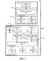
- FIG. 2 is a block diagram of a system 200 for determining motion of a handheld device relative to a user, in accordance with exemplary embodiments of the present disclosure.
- the system 200 comprises a handheld device 102 and a stylus 108.
- the stylus 108 includes motion and/or orientation sensors 202, memory 204 and communication sub-system 206, all of which are operationally coupled to a processor 208.
- the processor 208 implements an orientation module 210 that is operable to determine the orientation of the stylus 108 relative to the Earth. Signals characterizing the orientation of the stylus are passed to the communication sub-system 206, where they are transmitted.
- the motion and/or orientation sensors 202 may include, for example, accelerometers for tilt sensing, gyroscopes for rotational motion sensing and magnetic field sensors for sensing orientation relative to the Earth's magnetic field.
- the sensors (202) may include orientation sensors, such as a compass or a tilt sensor that provide direct measurement of orientation even if the device is stationary.
- the sensors (202) may include motion sensors, such as a gyroscope or accelerometer, from which a change in orientation can be calculated.
- the motion sensor signals may be processed to determine orientation, but additional information, such as a starting orientation, is needed. Starting orientation information may be provided by orientation sensors, or by placing the device in a known orientation, for example.
- An accelerometer may be responsive to both gravity and motion, providing a signal that includes both orientation and motion components.
- the sensors 202 and the orientation module 210 are provided in a single chip combining micro-machined sensors and processing circuitry.
- the signals transmitted from the stylus 108 are received by a communication module 214 of the handheld device 102.
- the communication module 214, motion and/or orientation sensors 216, system clock 218, display 220 and memory 222, are all operationally coupled to a processor 224.
- the processor 224 implements an orientation module 226 that is operable to determine the orientation of the handheld device 102 relative to the Earth in response to signals 228 from the sensors 216.
- the orientation module 226 provides, as output, orientation data 230 and motion data 232.
- the motion data 232 may be relative to a local frame of reference or to an absolute (Earth) frame of reference.
- the orientation data 230 describes the orientation of the handheld device relative to the absolute (Earth) frame of reference.
- Stylus orientation data 2344 descriptive of the absolute orientation of the stylus, are received from the communication module 214 and are used in compensation module 236 to determine the orientation and/or motion of the handheld device 102 relative to the stylus 108.
- the relative motion and/or orientation 238 may be passed to an application module 240 where it provides user input to the application.
- the motion and/or orientation of the handheld device relative to the absolute (Earth) frame of reference may also be passed to the application module 240.
- the absolute motion and/or orientation may be saved in the memory 222 or transmitted to a remote location via network interface 242.
- the system clock 218 may be used to provide synchronization between the sensed motion of the handheld device and the sensed motion of the stylus. This is discussed in more detail below.
- an exemplary embodiment relates to a handheld device having an orientation and/or motion sensors, a communication module operable to receive stylus orientation data from a remote stylus, the stylus orientation data descriptive of an absolute orientation of the stylus and a processor.
- the processor is operable to determine handheld device orientation data, descriptive of an absolute orientation of the handheld device, dependent upon signals from the orientation sensor, the motion sensor or a combination thereof, and to determine motion of the handheld device relative to the stylus, dependent upon the stylus orientation data and the handheld device orientation data.
- An application executed on the processor may be controlled dependent upon the motion of the handheld device relative to the stylus.
- the orientation sensor may comprise a tilt sensor (such as a three-axis accelerometer), a magnetic field sensor (such as a three-axis, Hall-effect sensor), or a combination thereof.
- the motion sensor may comprise a three-axis accelerometer, a three-axis gyroscope, or a combination thereof. Other sensors may be used without departing from the present disclosure.
- the processor may also be operable to control the application executed on the processor dependent upon an orientation of the handheld device relative to the orientation of the stylus, an orientation of the handheld device relative to an Earth frame of reference, and/or a motion of the handheld device relative to an Earth frame of reference.
- FIG. 3 is a flow chart 300 of a method for motion sensing by a handheld device, in accordance with some embodiments.
- the handheld device acts as a host device for a stylus and receives data from the stylus over a wired or wireless communication link.
- a processor of the handheld device connects to motion and/or orientation sensors of the handheld device at block 304.
- the handheld device retrieves local sensor data from these sensors.
- the local sensor data may comprise both orientation data (from a tilt sensor or electronic compass, for example) and motion data (from a gyroscope or accelerometer, for example).
- the sensors may be tri-axial sensors that provide motion or orientation vectors as output.
- the handheld device receives stylus orientation data from a remote stylus.
- the stylus orientation data is descriptive of an absolute orientation of the stylus and may comprise explicit orientation data, or data from which the orientation may be derived.
- the stylus orientation data is received via communication link and may comprise a serial data stream, for example, the data may not be time-aligned with the data from the local sensors of the handheld electronic device. Time misalignment may result from inherent delays when parallel data, such as a digital signal level, is serialized for transmission.
- the stylus orientation data is time-synchronized with the local data. Synchronization may be achieved, for example, by synchronizing clocks on the stylus and handheld device and then time-stamping the stylus orientation data before it is transmitted to the handheld electronic device.
- the local data of the host may be similarly time-stamped to allow time synchronization.
- timing information is retrieved at block 310 and the local data and stylus orientation data are time-aligned at block 312.
- Other methods of synchronization will be apparent to those of ordinary skill in the art. For example, in some embodiments the time-misalignment is fixed and may be predetermined or measured. Time alignment may then be achieved by delaying the local data by a corresponding amount.
- the relative orientation between the handheld device and the stylus is calculated from the synchronized stylus orientation data and handheld device orientation data. The relative orientation is used at block 316 to determine the motion of the handheld device relative to the stylus.
- the motion of the handheld device relative to the stylus is used in a software application executed on the handheld device, stored in a memory on the device and/or transmitted for use at a remote location (via a network, for example).
- the absolute orientation and/or motion of the electronic device relative to the frame of the Earth may also be determined at block 320 and provided to the software application.
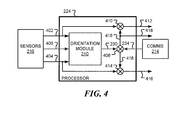
- FIG. 4 is a block diagram of part of a handheld electronic device, in accordance with certain embodiments of the disclosure.
- an orientation module 210 which may be implemented in hardware or software or a combination thereof, receives a first signal 402, representative of linear motion and/or orientation and denoted by a vector a, such as a signal from a three-axis accelerometer, a second signal 404, representative of rotational motion and/or orientation and denoted by a vector ⁇ , such as a signal from a three-axis gyroscope and a third signal 406, denoted by a vector n, such as a signal from an electronic compass or magnetic field sensor.
- a first signal 402 representative of linear motion and/or orientation and denoted by a vector a, such as a signal from a three-axis accelerometer
- a second signal 404 representative of rotational motion and/or orientation and denoted by a vector ⁇ , such as a signal from a three-axis gyr
- the first signal 402 may include both tilt (orientation) and shake (motion) components.
- the signals 402, 404, 406 are provided by sensors 216 of the handheld device.
- the orientation module 210 is operable to determine the orientation of the handheld device relative to the Earth. This orientation is described in orientation data 230.
- the orientation data may take the form of a quaternion, a rotation matrix, a rotation axis and rotation angle, or some other form.
- Corresponding orientation data 234 from a remote stylus is received via communication sub-system 214. By way of example, it is assumed that the orientation data is expressed as a rotation matrix that represents a rotation from the Earth frame of reference to the local frame of reference.
- n relative R s ⁇ R h T ⁇ n .
- the R s ⁇ R h T matrix (denoted as signal 418), which represents the relative orientation between the stylus and the handheld device, is computed at 408 by multiplying by the matrix R h T by the matrix R s .
- the combined matrix R s ⁇ R h T (418) is applied to the first signal (402), a, to obtain the linear motion and/or orientation 412 of the handheld device relative to the stylus.
- the combined matrix R s ⁇ R h T is applied to the second signal (404), ⁇ , to obtain the rotational motion 416 of the handheld device relative to the stylus.
- the relative motion vectors 412 and 416 may be used to control an application executed on the handheld device, may be stored in a memory, or transmitted, over a network or local wireless link, for example, to a remote device.
- the matrix R s ⁇ R h T may be output as signal 418.
- any module, component or sub-system disclosed herein that executes instructions may include or otherwise have access to non-transient and tangible computer readable media such as storage media, computer storage media, or data storage devices (removable or non-removable) such as, for example, magnetic disks, optical disks, or tape data storage.
- Computer storage media may include volatile and non-volatile, removable and non-removable media implemented in any method or technology for storage of information, such as computer readable instructions, data structures, program modules, or other data.
- Examples of computer storage media include RAM, ROM, EEPROM, flash memory or other memory technology, CD-ROM, digital versatile disks (DVD) or other optical storage, magnetic cassettes, magnetic tape, magnetic disk storage or other magnetic storage devices, or any other medium which can be used to store the desired information and which can be accessed by an application, module, or both. Any such computer storage media may be part of the server, any component of or related to the network, backend, etc., or accessible or connectable thereto. Any application or module herein described may be implemented using computer readable/executable instructions that may be stored or otherwise held by such computer readable media.
Landscapes
- Engineering & Computer Science (AREA)
- General Engineering & Computer Science (AREA)
- Theoretical Computer Science (AREA)
- Human Computer Interaction (AREA)
- Physics & Mathematics (AREA)
- General Physics & Mathematics (AREA)
- User Interface Of Digital Computer (AREA)
Abstract
Description
- A stylus is commonly used to identify positions on a touch screen or other sensing surface of a host electronic device so as to provide user input to the device. In addition, the tilt of a stylus relative to the Earth's gravitational field may be sensed to provide additional user input to the host device. Still further, the tilt of a stylus relative to a stationary sensing surface may be sensed.
- A handheld host device, such as gaming controller, tablet computer or 'smart' mobile telephone, may incorporate motion sensors such as accelerometers or gyroscopes. These motion sensors provide information related to dynamic motion of the handheld host device relative to the Earth. The information may be used, for example, to control remote or local software applications.
- When a user of a handheld host device is in motion, such as while walking or when using transportation, any such motion of the user that is detected by the motion sensor of the device may cause unintended inputs to the device. It would therefore be desirable to provide a method and apparatus to eliminate, or reduce, unintended inputs to the host device when a user is in motion.
- Exemplary embodiments of the present disclosure will be described below with reference to the included drawings such that like reference numerals refer to like elements and in which:
- FIG's. 1A-1C shows diagrammatic representations of a user and a handheld device in various orientations;
-
FIG. 2 is a block diagram of a system for determining motion of a handheld device relative to a user, in accordance with exemplary embodiments of the present disclosure; -
FIG. 3 is a flow chart of a method for motion sensing by a handheld electronic device, in accordance with exemplary embodiments of the present disclosure; and -
FIG. 4 is a block diagram of part of a handheld electronic device, in accordance with exemplary embodiments of the present disclosure. - For simplicity and clarity of illustration, reference numerals may be repeated among the figures to indicate corresponding or analogous elements. Numerous details are set forth to provide an understanding of the illustrative embodiments described herein. The exemplary embodiments may be practiced without these details. In other instances, well-known methods, procedures, and components have not been described in detail to avoid obscuring the disclosed embodiments. The description is not to be considered as limited to the scope of the embodiments shown and described herein.
- A handheld device, such as gaming controller, tablet computer or 'smart' mobile telephone, may incorporate motion sensors, such as accelerometers or gyroscopes. These motion sensors provide information related to dynamic motion of the handheld host device relative to the Earth. The information may be used, for example, to control software applications executed on the device or on a remote device. For example, tilt information from an accelerometer may be used by software applications executed on the device to ensure that an image displayed on a screen of the device maintains an approximately vertical orientation.
- One aspect of the disclosure relates to a handheld device and method of operation for determining motion of the handheld device relative to a stylus, in which the stylus is used to provide a frame of reference for the handheld device rather than as a user input device. Stylus orientation data, descriptive of an absolute orientation of a stylus, and handheld device orientation data, descriptive of an absolute orientation of the handheld device, are used to determine motion of the handheld device relative to the stylus. The handheld device has orientation and/or motion sensors, a communication module operable to receive stylus orientation data, and a processor operable to determine the motion or orientation of the handheld device relative to the stylus and execute an application dependent thereon.
- FIG's. 1A-1C show diagrammatic representations of a
user 100 and ahandheld device 102 in various orientations and viewed looking down from above. The handheld device may be, for example, a gaming controller, tablet computer, personal digital assistant, 'smart' mobile telephone, or the like.FIG. 1A shows an initial configuration.FIG. 1B shows a configuration where the orientation of theuser 100 is unchanged but thehandheld device 102 has been rotated through anangle 104 from the initial orientation.FIG. 1C shows a configuration where, relative to the initial positions shown inFIG. 1A , theuser 100 has been rotated through anangle 106 and thehandheld device 102 has been rotated through anangle 104. Rotation of the user may be due to the user turning to look or walk in a different direction, for example, or due to turning of a vehicle, such as an automobile, in which the user is travelling. - In this example, the
angles FIG. 1B thehandheld device 102 has been rotated relative to theuser 100, whereas inFIG. 1C , thehandheld device 102 has not been rotated relative to theuser 100. Prior orientation sensing techniques that rely on sensing motion of the handheld device are unable to distinguish between the situations shown infigures 1B and 1C . In prior techniques, the motion and orientation of the handheld device is measured relative to the Earth. An aspect of the present disclosure enables the motion or orientation of a handheld device to be determined relative to a moving frame of reference, such as a user or a vehicle, rather than relative to the absolute frame of reference of the Earth.
In accordance with an exemplary embodiment, a stylus 108 (shown in FIG's. 1A-1C) is provided that has orientation sensing or motion sensing capabilities, or both. To enable motion of the handheld device to be determined relative to theuser 100, the stylus is positioned on the body of the user as shown in FIG's 1A-1C (in a pocket, for example) or positioned to move with a vehicle in which the user is traveling. For example, the stylus could be placed on the dashboard of an automobile or in a storage compartment of the automobile. Information representative of the orientation or motion of the stylus is communicated to the handheld device, where it may be used to determine the orientation and/or motion of the handheld device relative to the stylus and, therefore, relative to the user or vehicle. Thus, rather than being used as a conventional hand-held input device, the stylus is used to provide a frame reference with respect to which motion and/or orientation of the handheld device (such as a tablet computer) is determined. Motion and/or orientation of the handheld device, relative the frame of reference provided by the stylus, is used to provide input to software applications executed on the device. - Another aspect of the present disclosure relates to a handheld device and a method executed on the handheld device for determining motion of a handheld device relative to a stylus. In an exemplary embodiment, stylus orientation data, descriptive of an absolute orientation of the stylus, is received from the stylus. Handheld device orientation data, descriptive of an absolute orientation of the handheld device, is determined dependent upon signals from sensors of the handheld device. The motion of the handheld device relative to the stylus is determined dependent upon the stylus orientation data and the handheld device orientation data.
- The handheld device orientation data may be determined dependent upon signals from one or more of: an accelerometer, a gyroscope and a magnetic field sensor of the handheld device.
- Similarly, the stylus orientation data may be determined dependent upon signals from one or more of: an accelerometer, a gyroscope and a magnetic field sensor of the stylus.
- The sensors may include micro-machined electro-mechanical systems (MEMS), for example. Multiple sensors may be integrated into a single chip or package. For example, a 3-axis accelerometer, a 3-axis gyroscope, and a 3-axis magnetic field sensor may be integrated in a single package.
- Local motion of the handheld device may be sensed to provide local motion data descriptive of handheld device motion in a frame of reference of the handheld device. In this embodiment, motion of the handheld device relative to the stylus is determined dependent upon this local motion data.
- The motion of the handheld device relative to the stylus may be determined by determining a relative orientation between the handheld device and the stylus dependent upon the stylus orientation data and the handheld device orientation data and rotating the local motion data dependent upon the relative orientation between the handheld device and the stylus.
- A software application executed on the handheld device may be controlled dependent upon the motion of the handheld device relative to the stylus. Optionally, the software application executed on the handheld device may be controlled dependent upon the motion of the handheld device relative to the Earth. The user may select via a user interface whether absolute or relative motion, or both, are to be used.
-
FIG. 2 is a block diagram of asystem 200 for determining motion of a handheld device relative to a user, in accordance with exemplary embodiments of the present disclosure. Thesystem 200 comprises ahandheld device 102 and astylus 108. Thestylus 108 includes motion and/ororientation sensors 202,memory 204 andcommunication sub-system 206, all of which are operationally coupled to aprocessor 208. Theprocessor 208 implements anorientation module 210 that is operable to determine the orientation of thestylus 108 relative to the Earth. Signals characterizing the orientation of the stylus are passed to thecommunication sub-system 206, where they are transmitted. The motion and/ororientation sensors 202 may include, for example, accelerometers for tilt sensing, gyroscopes for rotational motion sensing and magnetic field sensors for sensing orientation relative to the Earth's magnetic field. - The sensors (202) may include orientation sensors, such as a compass or a tilt sensor that provide direct measurement of orientation even if the device is stationary. The sensors (202) may include motion sensors, such as a gyroscope or accelerometer, from which a change in orientation can be calculated. The motion sensor signals may be processed to determine orientation, but additional information, such as a starting orientation, is needed. Starting orientation information may be provided by orientation sensors, or by placing the device in a known orientation, for example. An accelerometer may be responsive to both gravity and motion, providing a signal that includes both orientation and motion components.
- Techniques for combining signals from some, or all, of these sensors to obtain an absolute orientation, that is, an orientation relative to an Earth frame of reference, are well known to those of skill in the art. In an embodiment, the
sensors 202 and theorientation module 210 are provided in a single chip combining micro-machined sensors and processing circuitry. - In operation, the signals transmitted from the
stylus 108 are received by acommunication module 214 of thehandheld device 102. Thecommunication module 214, motion and/ororientation sensors 216,system clock 218,display 220 andmemory 222, are all operationally coupled to aprocessor 224. Theprocessor 224 implements anorientation module 226 that is operable to determine the orientation of thehandheld device 102 relative to the Earth in response tosignals 228 from thesensors 216. Theorientation module 226 provides, as output,orientation data 230 and motion data 232. The motion data 232 may be relative to a local frame of reference or to an absolute (Earth) frame of reference. Theorientation data 230 describes the orientation of the handheld device relative to the absolute (Earth) frame of reference. -
Stylus orientation data 234, descriptive of the absolute orientation of the stylus, are received from thecommunication module 214 and are used in compensation module 236 to determine the orientation and/or motion of thehandheld device 102 relative to thestylus 108. The relative motion and/ororientation 238 may be passed to anapplication module 240 where it provides user input to the application. Optionally, the motion and/or orientation of the handheld device relative to the absolute (Earth) frame of reference may also be passed to theapplication module 240. The absolute motion and/or orientation may be saved in thememory 222 or transmitted to a remote location vianetwork interface 242. - The
system clock 218 may be used to provide synchronization between the sensed motion of the handheld device and the sensed motion of the stylus. This is discussed in more detail below. - Thus, an exemplary embodiment relates to a handheld device having an orientation and/or motion sensors, a communication module operable to receive stylus orientation data from a remote stylus, the stylus orientation data descriptive of an absolute orientation of the stylus and a processor. The processor is operable to determine handheld device orientation data, descriptive of an absolute orientation of the handheld device, dependent upon signals from the orientation sensor, the motion sensor or a combination thereof, and to determine motion of the handheld device relative to the stylus, dependent upon the stylus orientation data and the handheld device orientation data. An application executed on the processor may be controlled dependent upon the motion of the handheld device relative to the stylus.
- The orientation sensor may comprise a tilt sensor (such as a three-axis accelerometer), a magnetic field sensor (such as a three-axis, Hall-effect sensor), or a combination thereof. The motion sensor may comprise a three-axis accelerometer, a three-axis gyroscope, or a combination thereof. Other sensors may be used without departing from the present disclosure.
- The processor may also be operable to control the application executed on the processor dependent upon an orientation of the handheld device relative to the orientation of the stylus, an orientation of the handheld device relative to an Earth frame of reference, and/or a motion of the handheld device relative to an Earth frame of reference.
-
FIG. 3 is aflow chart 300 of a method for motion sensing by a handheld device, in accordance with some embodiments. The handheld device acts as a host device for a stylus and receives data from the stylus over a wired or wireless communication link. Followingstart block 302 inFIG. 3 , a processor of the handheld device connects to motion and/or orientation sensors of the handheld device atblock 304. Atblock 306 the handheld device (the host) retrieves local sensor data from these sensors. The local sensor data may comprise both orientation data (from a tilt sensor or electronic compass, for example) and motion data (from a gyroscope or accelerometer, for example). The sensors may be tri-axial sensors that provide motion or orientation vectors as output. Atblock 308 the handheld device receives stylus orientation data from a remote stylus. The stylus orientation data is descriptive of an absolute orientation of the stylus and may comprise explicit orientation data, or data from which the orientation may be derived. - Since the stylus orientation data is received via communication link and may comprise a serial data stream, for example, the data may not be time-aligned with the data from the local sensors of the handheld electronic device. Time misalignment may result from inherent delays when parallel data, such as a digital signal level, is serialized for transmission. In an exemplary embodiment, the stylus orientation data is time-synchronized with the local data. Synchronization may be achieved, for example, by synchronizing clocks on the stylus and handheld device and then time-stamping the stylus orientation data before it is transmitted to the handheld electronic device. The local data of the host may be similarly time-stamped to allow time synchronization. To perform time-synchronization, timing information is retrieved at
block 310 and the local data and stylus orientation data are time-aligned atblock 312. Other methods of synchronization will be apparent to those of ordinary skill in the art. For example, in some embodiments the time-misalignment is fixed and may be predetermined or measured. Time alignment may then be achieved by delaying the local data by a corresponding amount. Atblock 314, the relative orientation between the handheld device and the stylus is calculated from the synchronized stylus orientation data and handheld device orientation data. The relative orientation is used atblock 316 to determine the motion of the handheld device relative to the stylus. This may be achieved, for example, by (a) representing the motion as a vector of linear or rotational motion, (b) representing the relative orientation as a rotation matrix, and (c) applying the rotation matrix to the motion vector. Atblock 318, the motion of the handheld device relative to the stylus is used in a software application executed on the handheld device, stored in a memory on the device and/or transmitted for use at a remote location (via a network, for example). The absolute orientation and/or motion of the electronic device relative to the frame of the Earth may also be determined atblock 320 and provided to the software application. -
FIG. 4 is a block diagram of part of a handheld electronic device, in accordance with certain embodiments of the disclosure. In the embodiment shown, anorientation module 210, which may be implemented in hardware or software or a combination thereof, receives afirst signal 402, representative of linear motion and/or orientation and denoted by a vector a, such as a signal from a three-axis accelerometer, asecond signal 404, representative of rotational motion and/or orientation and denoted by a vector ω, such as a signal from a three-axis gyroscope and a third signal 406, denoted by a vector n, such as a signal from an electronic compass or magnetic field sensor. Thefirst signal 402 may include both tilt (orientation) and shake (motion) components. Thesignals sensors 216 of the handheld device. Theorientation module 210 is operable to determine the orientation of the handheld device relative to the Earth. This orientation is described inorientation data 230. The orientation data may take the form of a quaternion, a rotation matrix, a rotation axis and rotation angle, or some other form. Correspondingorientation data 234 from a remote stylus is received viacommunication sub-system 214. By way of example, it is assumed that the orientation data is expressed as a rotation matrix that represents a rotation from the Earth frame of reference to the local frame of reference. Denoting the orientation of the handheld device as Rh and the orientation of the stylus as Rs, the linear motion vector of the handheld device relative to the stylus is computed as
and a relative rotational motion vector is computed to be
- Similarly, a relative orientation vector of the handheld device is computed as

- In the above, the superposed 'T' denotes a matrix transpose. These computations are depicted in
FIG. 4 . The


rotational motion 416 of the handheld device relative to the stylus. Therelative motion vectors 412 and 416 may be used to control an application executed on the handheld device, may be stored in a memory, or transmitted, over a network or local wireless link, for example, to a remote device. - Optionally, the matrix

signal 418. - These expressions assume that the orientations of the handheld device and the stylus vary slowly. More complex computations may be employed if the orientations vary more rapidly; such computations will be apparent to those of ordinary skill in the art.
- It will be appreciated that any module, component or sub-system disclosed herein that executes instructions may include or otherwise have access to non-transient and tangible computer readable media such as storage media, computer storage media, or data storage devices (removable or non-removable) such as, for example, magnetic disks, optical disks, or tape data storage. Computer storage media may include volatile and non-volatile, removable and non-removable media implemented in any method or technology for storage of information, such as computer readable instructions, data structures, program modules, or other data. Examples of computer storage media include RAM, ROM, EEPROM, flash memory or other memory technology, CD-ROM, digital versatile disks (DVD) or other optical storage, magnetic cassettes, magnetic tape, magnetic disk storage or other magnetic storage devices, or any other medium which can be used to store the desired information and which can be accessed by an application, module, or both. Any such computer storage media may be part of the server, any component of or related to the network, backend, etc., or accessible or connectable thereto. Any application or module herein described may be implemented using computer readable/executable instructions that may be stored or otherwise held by such computer readable media.
- The implementations of the present disclosure described above are intended to be merely exemplary. It will be appreciated by those of skill in the art that alterations, modifications and variations to the illustrative embodiments disclosed herein may be made without departing from the scope of the present disclosure. Moreover, selected features from one or more of the above-described embodiments may be combined to create alternative embodiments not explicitly shown and described herein.
- The present disclosure may be embodied in other specific forms without departing from its essential characteristics. The described exemplary embodiments are to be considered in all respects only as illustrative and not restrictive. The scope of the disclosure is, therefore, indicated by the appended claims rather than by the foregoing description. All changes that come within the meaning and range of equivalency of the claims are to be embraced within their scope.
- Examples are set out in the following list of numbered clauses:
- 1. A method for determining motion of a handheld device relative to a stylus, the method comprising:
- receiving, from the stylus, stylus orientation data comprising data descriptive of an absolute orientation of the stylus;
- determining handheld device orientation data, descriptive of an absolute orientation of the handheld device, from signals from sensors of the handheld device; and
- determining motion of the handheld device relative to the stylus from the stylus orientation data and the handheld device orientation data.
- 2. The method of clause 1, where determining the handheld device orientation data comprises determining the handheld device orientation dependent upon signals from one or more of: an accelerometer, a gyroscope and a magnetic field sensor of the handheld device.
- 3. The method of clause 1, further comprising sensing local motion of the handheld device to provide local motion data descriptive of handheld device motion in a frame of reference of the handheld device, where determining motion of the handheld device relative to the stylus is further dependent upon the local motion data.
- 4. The method of clause 3, where determining motion of the handheld device relative to the stylus comprises:
- determining a relative orientation between the handheld device and the
- stylus dependent upon the stylus orientation data and the handheld device orientation data; and
- rotating the local motion data dependent upon the relative orientation between the handheld device and the stylus.
- 5. The method of clause 1, further comprising:
- controlling a software application executed on the handheld device in response to the motion of the handheld device relative to the stylus.
- 6. The method of clause 1, further comprising:
- in response to user input, selecting if a software application executed on the handheld device is to be controlled in response to an absolute motion of the handheld device or in response to a motion of the handheld device relative to the stylus.
- 7. The method of clause 1, further comprising time-aligning the stylus orientation data and the handheld device orientation data.
- 8. The method of clause 1, further comprising:
- determining orientation of the handheld device relative to the stylus from the stylus orientation data and the handheld device orientation data.
- 9. A handheld device comprising:
- one or more sensors operable to provide sensor signals in response to motion or orientation of the handheld device;
- a communication module operable to receive stylus orientation data from a stylus, the stylus orientation data descriptive of an absolute orientation of the stylus; and
- a processor coupled to the one or more sensors and the communication module and operable to:
- determine handheld device orientation data, descriptive of an absolute orientation of the handheld device, from sensor signals;
- determine motion of the handheld device relative to the stylus from the stylus orientation data and the handheld device orientation data; and
- execute an application dependent upon the motion of the handheld device relative to the stylus.
- 10. The handheld device of clause 9, where the processor is further operable to:
- determine orientation of the handheld device relative to the stylus from the stylus orientation data and the handheld device orientation data; and
- execute an application dependent upon the orientation of the handheld device relative to the stylus.
- 11. The handheld device of clause 9, where the one or more sensors comprise a tilt sensor, a magnetic field sensor, or a combination thereof.
- 12. The handheld device of clause 9, where the one or more sensors comprise an accelerometer, a gyroscope, or a combination thereof.
- 13. The handheld device of clause 9, where the processor is further operable to execute the application in response to an orientation of the handheld device relative to the orientation of the stylus.
- 14. The handheld device of clause 9, where the processor is further operable to execute the application in response to an orientation of the handheld device relative to an absolute frame of reference.
- 15. The handheld device of clause 9, where the processor is further operable to execute the application in response to a motion of the handheld device relative to an absolute frame of reference.
- 16. The handheld device of clause 9, further comprising a clock, where the handheld device is operable to time-align the stylus orientation data and the handheld device orientation data in response to a timing signal provided by the clock.
- 17. The handheld device of clause 9, where the handheld device comprises a tablet computer.
- 18. The handheld device of clause 9, where the handheld device comprises a mobile telephone.
- 19. A method executed on a handheld device, the method comprising:
- determining motion of the handheld device relative to a stylus, dependent upon:
- stylus orientation data descriptive of an orientation of the stylus and received through communication with the stylus;
- orientation data descriptive of an orientation of the handheld device; and
- sensed motion of the handheld device; and
- executing an application dependent upon the determined motion of the handheld device relative to the stylus.
- determining motion of the handheld device relative to a stylus, dependent upon:
- 20. The method of clause 19, further comprising executing an application dependent upon one or more of:
- an orientation of the handheld device relative to the orientation of the stylus;
- an orientation of the handheld device relative to an absolute frame of reference; and
- motion of the handheld device relative to the absolute frame of reference.
- 21. The method of clause 19, further comprising transmitting to a remote device a description of the motion of the handheld device relative to the stylus.
Claims (15)
- A method for determining motion of a handheld device (102) relative to a stylus (108), the method comprising:receiving, from the stylus (108), stylus orientation data (234) comprising data descriptive of an absolute orientation of the stylus;determining handheld device orientation data (230), descriptive of an absolute orientation of the handheld device, from signals from sensors (216) of the handheld device (102); anddetermining motion (238) of the handheld device (102) relative to the stylus (108) from the stylus orientation data (234) and the handheld device orientation data (230).
- The method of claim 1, where determining the handheld device orientation data (230) comprises determining the handheld device orientation dependent upon signals from one or more of: an accelerometer, a gyroscope and a magnetic field sensor of the handheld device (102).
- The method of claim 1, further comprising sensing local motion (228) of the handheld device to provide local motion data descriptive of handheld device motion in a frame of reference of the handheld device (102), where determining motion (238) of the handheld device (102) relative to the stylus (102) is further dependent upon the local motion data (228).
- The method of claim 3, where determining motion (238) of the handheld device relative to the stylus comprises:determining a relative orientation between the handheld device (102) and the stylus (108) dependent upon the stylus orientation data (234) and the handheld device orientation data (230); androtating the local motion data (228) dependent upon the relative orientation between the handheld device (102) and the stylus (108).
- The method of claim 1, further comprising:controlling a software application (240) executed on the handheld device (102) in response to the motion (238) of the handheld device (102) relative to the stylus (108).
- The method of claim 1, further comprising:in response to user input, selecting if a software application (240) executed on the handheld device (102) is to be controlled in response to an absolute motion (228) of the handheld device or in response to a motion (238) of the handheld device relative to the stylus.
- The method of claim 1, further comprising time-aligning the stylus orientation data (234) and the handheld device orientation data (230).
- The method of claim 1, further comprising:determining orientation of the handheld device (102) relative to the stylus (108) from the stylus orientation data (234) and the handheld device orientation data (230).
- A method executed on a handheld device (102), the method comprising:determining motion (238) of the handheld device relative to a stylus (108), dependent upon:stylus orientation data (234) descriptive of an orientation of the stylus (234) and received through communication with the stylus;orientation data (230) descriptive of an orientation of the handheld device (102); andsensed motion (228) of the handheld device (102); andexecuting an application (240) dependent upon the determined motion (238) of the handheld device (102) relative to the stylus (108).
- The method of claim 9, further comprising executing the application (240) dependent upon one or more of:an orientation of the handheld device (102) relative to the orientation of the stylus (108);an orientation (230) of the handheld device (102) relative to an absolute frame of reference; andmotion (228) of the handheld device (102) relative to the absolute frame of reference.
- A handheld device (102) comprising:one or more sensors (216) operable to provide sensor signals (228) in response to motion or orientation of the handheld device (102);a communication module (214) operable to receive stylus orientation data (234) from a stylus (108), the stylus orientation data (234) descriptive of an absolute orientation of the stylus (108); anda processor (224) coupled to the one or more sensors (216) and the communication module (214) and operable to:determine handheld device orientation data (230), descriptive of an absolute orientation of the handheld device (102), from sensor signals (228);determine motion (238) of the handheld device (102) relative to the stylus (108) from the stylus orientation data (234) and the handheld device orientation data (230); andexecute an application (240) dependent upon the motion (238) of the handheld device (102) relative to the stylus (108).
- The handheld device (102) of claim 11, where the processor (224) is further operable to:determine orientation of the handheld device relative to the stylus from the stylus orientation data (234) and the handheld device orientation data (230); andexecute an application (240) dependent upon the orientation of the handheld device (102) relative to the stylus (108).
- The handheld device (102) of claim 11, where the one or more sensors (216) comprise a tilt sensor, a magnetic field sensor, an accelerometer, a gyroscope, or a combination thereof.
- The handheld device (102) of claim 11 where the processor (240) is further operable to execute the application (240) in response to one or more of:an orientation of the handheld device (102) relative to the orientation of the stylus (108);an orientation (230) of the handheld device (102) relative to an absolute frame of reference; anda motion (228) of the handheld device (102) relative to an absolute frame of reference.
- The handheld device (102) of claim 11, further comprising a clock (218), where the handheld device (102) is operable to time-align the stylus orientation data (234) and the handheld device orientation data (230) in response to a timing signal provided by the clock (218).
Priority Applications (1)
| Application Number | Priority Date | Filing Date | Title |
|---|---|---|---|
| EP13174804.8A EP2821896B1 (en) | 2013-07-02 | 2013-07-02 | Method and Apparatus for Motion sensing of a handheld Device relative to a Stylus |
Applications Claiming Priority (1)
| Application Number | Priority Date | Filing Date | Title |
|---|---|---|---|
| EP13174804.8A EP2821896B1 (en) | 2013-07-02 | 2013-07-02 | Method and Apparatus for Motion sensing of a handheld Device relative to a Stylus |
Publications (2)
| Publication Number | Publication Date |
|---|---|
| EP2821896A1 true EP2821896A1 (en) | 2015-01-07 |
| EP2821896B1 EP2821896B1 (en) | 2018-11-28 |
Family
ID=48745777
Family Applications (1)
| Application Number | Title | Priority Date | Filing Date |
|---|---|---|---|
| EP13174804.8A Active EP2821896B1 (en) | 2013-07-02 | 2013-07-02 | Method and Apparatus for Motion sensing of a handheld Device relative to a Stylus |
Country Status (1)
| Country | Link |
|---|---|
| EP (1) | EP2821896B1 (en) |
Citations (5)
| Publication number | Priority date | Publication date | Assignee | Title |
|---|---|---|---|---|
| US20020140666A1 (en) * | 2001-03-29 | 2002-10-03 | Bradski Gary R. | Intuitive mobile device interface to virtual spaces |
| US20090191920A1 (en) * | 2008-01-29 | 2009-07-30 | Paul Regen | Multi-Function Electronic Ear Piece |
| US20090239591A1 (en) * | 2008-03-19 | 2009-09-24 | Motorola Inc | Wireless communication device and method with an orientation detector |
| WO2009118054A1 (en) * | 2008-03-26 | 2009-10-01 | Sony Ericsson Mobile Communications Ab | Headset |
| US20110304537A1 (en) * | 2010-06-11 | 2011-12-15 | Qualcomm Incorporated | Auto-correction for mobile receiver with pointing technology |
-
2013
- 2013-07-02 EP EP13174804.8A patent/EP2821896B1/en active Active
Patent Citations (5)
| Publication number | Priority date | Publication date | Assignee | Title |
|---|---|---|---|---|
| US20020140666A1 (en) * | 2001-03-29 | 2002-10-03 | Bradski Gary R. | Intuitive mobile device interface to virtual spaces |
| US20090191920A1 (en) * | 2008-01-29 | 2009-07-30 | Paul Regen | Multi-Function Electronic Ear Piece |
| US20090239591A1 (en) * | 2008-03-19 | 2009-09-24 | Motorola Inc | Wireless communication device and method with an orientation detector |
| WO2009118054A1 (en) * | 2008-03-26 | 2009-10-01 | Sony Ericsson Mobile Communications Ab | Headset |
| US20110304537A1 (en) * | 2010-06-11 | 2011-12-15 | Qualcomm Incorporated | Auto-correction for mobile receiver with pointing technology |
Also Published As
| Publication number | Publication date |
|---|---|
| EP2821896B1 (en) | 2018-11-28 |
Similar Documents
| Publication | Publication Date | Title |
|---|---|---|
| US9280214B2 (en) | Method and apparatus for motion sensing of a handheld device relative to a stylus | |
| US9367960B2 (en) | Body-locked placement of augmented reality objects | |
| US11321870B2 (en) | Camera attitude tracking method and apparatus, device, and system | |
| US8957909B2 (en) | System and method for compensating for drift in a display of a user interface state | |
| US20150247729A1 (en) | System and method for device bearing estimation | |
| EP2933605A1 (en) | A device orientation correction method for panorama images | |
| EP1501051A2 (en) | Position and orientation detection method and apparatus | |
| KR101656025B1 (en) | Method and computer program for controlling object in virtual reality interface system based on motion recognition of user | |
| KR20180075191A (en) | Method and electronic device for controlling unmanned aerial vehicle | |
| US20150169171A1 (en) | No-touch cursor for item selection | |
| JP2011075559A (en) | Motion detecting device and method | |
| WO2013148588A1 (en) | Managing power consumption of a device with a gyroscope | |
| US20190041978A1 (en) | User defined head gestures methods and apparatus | |
| US20160349078A1 (en) | Gyroscope stabilizer filter | |
| CN110146106A (en) | Inertial navigation set scaling method, device, electronic equipment and storage medium | |
| US10247558B2 (en) | Travel direction determination apparatus, map matching apparatus, travel direction determination method, and computer readable medium | |
| EP3588003A1 (en) | Program, information-processing device, information-processing system, and information-processing method | |
| US10197402B2 (en) | Travel direction information output apparatus, map matching apparatus, travel direction information output method, and computer readable medium | |
| KR101525224B1 (en) | A portable terminal of having the auto photographing mode | |
| EP2821896B1 (en) | Method and Apparatus for Motion sensing of a handheld Device relative to a Stylus | |
| JP2019114036A (en) | Information processing apparatus, flight control instruction method, program, and recording medium | |
| Kannan et al. | Adaptive sensor fusion technology for mobile and wearable applications | |
| EP3093614B1 (en) | System and method for estimating three-dimensional measurements of physical objects | |
| TW201447344A (en) | Object orientation tracker | |
| KR101696607B1 (en) | Computer program storing recording medium for real-time controlling object in virtual reality interface system |
Legal Events
| Date | Code | Title | Description |
|---|---|---|---|
| PUAI | Public reference made under article 153(3) epc to a published international application that has entered the european phase |
Free format text: ORIGINAL CODE: 0009012 |
|
| 17P | Request for examination filed |
Effective date: 20130702 |
|
| AK | Designated contracting states |
Kind code of ref document: A1 Designated state(s): AL AT BE BG CH CY CZ DE DK EE ES FI FR GB GR HR HU IE IS IT LI LT LU LV MC MK MT NL NO PL PT RO RS SE SI SK SM TR |
|
| AX | Request for extension of the european patent |
Extension state: BA ME |
|
| GRAP | Despatch of communication of intention to grant a patent |
Free format text: ORIGINAL CODE: EPIDOSNIGR1 |
|
| STAA | Information on the status of an ep patent application or granted ep patent |
Free format text: STATUS: GRANT OF PATENT IS INTENDED |
|
| INTG | Intention to grant announced |
Effective date: 20180620 |
|
| GRAS | Grant fee paid |
Free format text: ORIGINAL CODE: EPIDOSNIGR3 |
|
| GRAA | (expected) grant |
Free format text: ORIGINAL CODE: 0009210 |
|
| STAA | Information on the status of an ep patent application or granted ep patent |
Free format text: STATUS: THE PATENT HAS BEEN GRANTED |
|
| AK | Designated contracting states |
Kind code of ref document: B1 Designated state(s): AL AT BE BG CH CY CZ DE DK EE ES FI FR GB GR HR HU IE IS IT LI LT LU LV MC MK MT NL NO PL PT RO RS SE SI SK SM TR |
|
| REG | Reference to a national code |
Ref country code: CH Ref legal event code: EP |
|
| REG | Reference to a national code |
Ref country code: AT Ref legal event code: REF Ref document number: 1070987 Country of ref document: AT Kind code of ref document: T Effective date: 20181215 |
|
| REG | Reference to a national code |
Ref country code: DE Ref legal event code: R096 Ref document number: 602013047374 Country of ref document: DE |
|
| REG | Reference to a national code |
Ref country code: IE Ref legal event code: FG4D |
|
| REG | Reference to a national code |
Ref country code: NL Ref legal event code: MP Effective date: 20181128 |
|
| REG | Reference to a national code |
Ref country code: LT Ref legal event code: MG4D |
|
| REG | Reference to a national code |
Ref country code: AT Ref legal event code: MK05 Ref document number: 1070987 Country of ref document: AT Kind code of ref document: T Effective date: 20181128 |
|
| PG25 | Lapsed in a contracting state [announced via postgrant information from national office to epo] |
Ref country code: LV Free format text: LAPSE BECAUSE OF FAILURE TO SUBMIT A TRANSLATION OF THE DESCRIPTION OR TO PAY THE FEE WITHIN THE PRESCRIBED TIME-LIMIT Effective date: 20181128 Ref country code: AT Free format text: LAPSE BECAUSE OF FAILURE TO SUBMIT A TRANSLATION OF THE DESCRIPTION OR TO PAY THE FEE WITHIN THE PRESCRIBED TIME-LIMIT Effective date: 20181128 Ref country code: FI Free format text: LAPSE BECAUSE OF FAILURE TO SUBMIT A TRANSLATION OF THE DESCRIPTION OR TO PAY THE FEE WITHIN THE PRESCRIBED TIME-LIMIT Effective date: 20181128 Ref country code: BG Free format text: LAPSE BECAUSE OF FAILURE TO SUBMIT A TRANSLATION OF THE DESCRIPTION OR TO PAY THE FEE WITHIN THE PRESCRIBED TIME-LIMIT Effective date: 20190228 Ref country code: IS Free format text: LAPSE BECAUSE OF FAILURE TO SUBMIT A TRANSLATION OF THE DESCRIPTION OR TO PAY THE FEE WITHIN THE PRESCRIBED TIME-LIMIT Effective date: 20190328 Ref country code: NO Free format text: LAPSE BECAUSE OF FAILURE TO SUBMIT A TRANSLATION OF THE DESCRIPTION OR TO PAY THE FEE WITHIN THE PRESCRIBED TIME-LIMIT Effective date: 20190228 Ref country code: HR Free format text: LAPSE BECAUSE OF FAILURE TO SUBMIT A TRANSLATION OF THE DESCRIPTION OR TO PAY THE FEE WITHIN THE PRESCRIBED TIME-LIMIT Effective date: 20181128 Ref country code: LT Free format text: LAPSE BECAUSE OF FAILURE TO SUBMIT A TRANSLATION OF THE DESCRIPTION OR TO PAY THE FEE WITHIN THE PRESCRIBED TIME-LIMIT Effective date: 20181128 Ref country code: ES Free format text: LAPSE BECAUSE OF FAILURE TO SUBMIT A TRANSLATION OF THE DESCRIPTION OR TO PAY THE FEE WITHIN THE PRESCRIBED TIME-LIMIT Effective date: 20181128 |
|
| PG25 | Lapsed in a contracting state [announced via postgrant information from national office to epo] |
Ref country code: SE Free format text: LAPSE BECAUSE OF FAILURE TO SUBMIT A TRANSLATION OF THE DESCRIPTION OR TO PAY THE FEE WITHIN THE PRESCRIBED TIME-LIMIT Effective date: 20181128 Ref country code: PT Free format text: LAPSE BECAUSE OF FAILURE TO SUBMIT A TRANSLATION OF THE DESCRIPTION OR TO PAY THE FEE WITHIN THE PRESCRIBED TIME-LIMIT Effective date: 20190328 Ref country code: GR Free format text: LAPSE BECAUSE OF FAILURE TO SUBMIT A TRANSLATION OF THE DESCRIPTION OR TO PAY THE FEE WITHIN THE PRESCRIBED TIME-LIMIT Effective date: 20190301 Ref country code: AL Free format text: LAPSE BECAUSE OF FAILURE TO SUBMIT A TRANSLATION OF THE DESCRIPTION OR TO PAY THE FEE WITHIN THE PRESCRIBED TIME-LIMIT Effective date: 20181128 Ref country code: RS Free format text: LAPSE BECAUSE OF FAILURE TO SUBMIT A TRANSLATION OF THE DESCRIPTION OR TO PAY THE FEE WITHIN THE PRESCRIBED TIME-LIMIT Effective date: 20181128 |
|
| PG25 | Lapsed in a contracting state [announced via postgrant information from national office to epo] |
Ref country code: NL Free format text: LAPSE BECAUSE OF FAILURE TO SUBMIT A TRANSLATION OF THE DESCRIPTION OR TO PAY THE FEE WITHIN THE PRESCRIBED TIME-LIMIT Effective date: 20181128 |
|
| PG25 | Lapsed in a contracting state [announced via postgrant information from national office to epo] |
Ref country code: CZ Free format text: LAPSE BECAUSE OF FAILURE TO SUBMIT A TRANSLATION OF THE DESCRIPTION OR TO PAY THE FEE WITHIN THE PRESCRIBED TIME-LIMIT Effective date: 20181128 Ref country code: PL Free format text: LAPSE BECAUSE OF FAILURE TO SUBMIT A TRANSLATION OF THE DESCRIPTION OR TO PAY THE FEE WITHIN THE PRESCRIBED TIME-LIMIT Effective date: 20181128 Ref country code: IT Free format text: LAPSE BECAUSE OF FAILURE TO SUBMIT A TRANSLATION OF THE DESCRIPTION OR TO PAY THE FEE WITHIN THE PRESCRIBED TIME-LIMIT Effective date: 20181128 Ref country code: DK Free format text: LAPSE BECAUSE OF FAILURE TO SUBMIT A TRANSLATION OF THE DESCRIPTION OR TO PAY THE FEE WITHIN THE PRESCRIBED TIME-LIMIT Effective date: 20181128 |
|
| REG | Reference to a national code |
Ref country code: DE Ref legal event code: R097 Ref document number: 602013047374 Country of ref document: DE |
|
| PG25 | Lapsed in a contracting state [announced via postgrant information from national office to epo] |
Ref country code: RO Free format text: LAPSE BECAUSE OF FAILURE TO SUBMIT A TRANSLATION OF THE DESCRIPTION OR TO PAY THE FEE WITHIN THE PRESCRIBED TIME-LIMIT Effective date: 20181128 Ref country code: SK Free format text: LAPSE BECAUSE OF FAILURE TO SUBMIT A TRANSLATION OF THE DESCRIPTION OR TO PAY THE FEE WITHIN THE PRESCRIBED TIME-LIMIT Effective date: 20181128 Ref country code: EE Free format text: LAPSE BECAUSE OF FAILURE TO SUBMIT A TRANSLATION OF THE DESCRIPTION OR TO PAY THE FEE WITHIN THE PRESCRIBED TIME-LIMIT Effective date: 20181128 Ref country code: SM Free format text: LAPSE BECAUSE OF FAILURE TO SUBMIT A TRANSLATION OF THE DESCRIPTION OR TO PAY THE FEE WITHIN THE PRESCRIBED TIME-LIMIT Effective date: 20181128 |
|
| PLBE | No opposition filed within time limit |
Free format text: ORIGINAL CODE: 0009261 |
|
| STAA | Information on the status of an ep patent application or granted ep patent |
Free format text: STATUS: NO OPPOSITION FILED WITHIN TIME LIMIT |
|
| PG25 | Lapsed in a contracting state [announced via postgrant information from national office to epo] |
Ref country code: SI Free format text: LAPSE BECAUSE OF FAILURE TO SUBMIT A TRANSLATION OF THE DESCRIPTION OR TO PAY THE FEE WITHIN THE PRESCRIBED TIME-LIMIT Effective date: 20181128 |
|
| 26N | No opposition filed |
Effective date: 20190829 |
|
| PG25 | Lapsed in a contracting state [announced via postgrant information from national office to epo] |
Ref country code: MC Free format text: LAPSE BECAUSE OF FAILURE TO SUBMIT A TRANSLATION OF THE DESCRIPTION OR TO PAY THE FEE WITHIN THE PRESCRIBED TIME-LIMIT Effective date: 20181128 |
|
| REG | Reference to a national code |
Ref country code: CH Ref legal event code: PL |
|
| PG25 | Lapsed in a contracting state [announced via postgrant information from national office to epo] |
Ref country code: TR Free format text: LAPSE BECAUSE OF FAILURE TO SUBMIT A TRANSLATION OF THE DESCRIPTION OR TO PAY THE FEE WITHIN THE PRESCRIBED TIME-LIMIT Effective date: 20181128 |
|
| REG | Reference to a national code |
Ref country code: BE Ref legal event code: MM Effective date: 20190731 |
|
| PG25 | Lapsed in a contracting state [announced via postgrant information from national office to epo] |
Ref country code: LU Free format text: LAPSE BECAUSE OF NON-PAYMENT OF DUE FEES Effective date: 20190702 Ref country code: BE Free format text: LAPSE BECAUSE OF NON-PAYMENT OF DUE FEES Effective date: 20190731 Ref country code: CH Free format text: LAPSE BECAUSE OF NON-PAYMENT OF DUE FEES Effective date: 20190731 Ref country code: LI Free format text: LAPSE BECAUSE OF NON-PAYMENT OF DUE FEES Effective date: 20190731 |
|
| PG25 | Lapsed in a contracting state [announced via postgrant information from national office to epo] |
Ref country code: IE Free format text: LAPSE BECAUSE OF NON-PAYMENT OF DUE FEES Effective date: 20190702 |
|
| PG25 | Lapsed in a contracting state [announced via postgrant information from national office to epo] |
Ref country code: CY Free format text: LAPSE BECAUSE OF FAILURE TO SUBMIT A TRANSLATION OF THE DESCRIPTION OR TO PAY THE FEE WITHIN THE PRESCRIBED TIME-LIMIT Effective date: 20181128 |
|
| PG25 | Lapsed in a contracting state [announced via postgrant information from national office to epo] |
Ref country code: MT Free format text: LAPSE BECAUSE OF FAILURE TO SUBMIT A TRANSLATION OF THE DESCRIPTION OR TO PAY THE FEE WITHIN THE PRESCRIBED TIME-LIMIT Effective date: 20181128 Ref country code: HU Free format text: LAPSE BECAUSE OF FAILURE TO SUBMIT A TRANSLATION OF THE DESCRIPTION OR TO PAY THE FEE WITHIN THE PRESCRIBED TIME-LIMIT; INVALID AB INITIO Effective date: 20130702 |
|
| PG25 | Lapsed in a contracting state [announced via postgrant information from national office to epo] |
Ref country code: MK Free format text: LAPSE BECAUSE OF FAILURE TO SUBMIT A TRANSLATION OF THE DESCRIPTION OR TO PAY THE FEE WITHIN THE PRESCRIBED TIME-LIMIT Effective date: 20181128 |
|
| REG | Reference to a national code |
Ref country code: DE Ref legal event code: R082 Ref document number: 602013047374 Country of ref document: DE Ref country code: DE Ref legal event code: R081 Ref document number: 602013047374 Country of ref document: DE Owner name: MALIKIE INNOVATIONS LTD., IE Free format text: FORMER OWNER: BLACKBERRY LIMITED, WATERLOO, ONTARIO, CA |
|
| REG | Reference to a national code |
Ref country code: GB Ref legal event code: 732E Free format text: REGISTERED BETWEEN 20240620 AND 20240627 |
|
| PGFP | Annual fee paid to national office [announced via postgrant information from national office to epo] |
Ref country code: DE Payment date: 20250728 Year of fee payment: 13 |
|
| PGFP | Annual fee paid to national office [announced via postgrant information from national office to epo] |
Ref country code: GB Payment date: 20250722 Year of fee payment: 13 |
|
| PGFP | Annual fee paid to national office [announced via postgrant information from national office to epo] |
Ref country code: FR Payment date: 20250725 Year of fee payment: 13 |