EP2821877A2 - Robotic-mounted monument system for metrology systems - Google Patents
Robotic-mounted monument system for metrology systems Download PDFInfo
- Publication number
- EP2821877A2 EP2821877A2 EP14175316.0A EP14175316A EP2821877A2 EP 2821877 A2 EP2821877 A2 EP 2821877A2 EP 14175316 A EP14175316 A EP 14175316A EP 2821877 A2 EP2821877 A2 EP 2821877A2
- Authority
- EP
- European Patent Office
- Prior art keywords
- monuments
- measurement systems
- environment
- coordinate system
- reference coordinate
- Prior art date
- Legal status (The legal status is an assumption and is not a legal conclusion. Google has not performed a legal analysis and makes no representation as to the accuracy of the status listed.)
- Granted
Links
Images




Classifications
-
- G—PHYSICS
- G05—CONTROLLING; REGULATING
- G05D—SYSTEMS FOR CONTROLLING OR REGULATING NON-ELECTRIC VARIABLES
- G05D1/00—Control of position, course, altitude or attitude of land, water, air or space vehicles, e.g. using automatic pilots
- G05D1/02—Control of position or course in two dimensions
- G05D1/021—Control of position or course in two dimensions specially adapted to land vehicles
- G05D1/0287—Control of position or course in two dimensions specially adapted to land vehicles involving a plurality of land vehicles, e.g. fleet or convoy travelling
- G05D1/0291—Fleet control
-
- G—PHYSICS
- G05—CONTROLLING; REGULATING
- G05B—CONTROL OR REGULATING SYSTEMS IN GENERAL; FUNCTIONAL ELEMENTS OF SUCH SYSTEMS; MONITORING OR TESTING ARRANGEMENTS FOR SUCH SYSTEMS OR ELEMENTS
- G05B19/00—Program-control systems
- G05B19/02—Program-control systems electric
- G05B19/418—Total factory control, i.e. centrally controlling a plurality of machines, e.g. direct or distributed numerical control [DNC], flexible manufacturing systems [FMS], integrated manufacturing systems [IMS] or computer integrated manufacturing [CIM]
- G05B19/41815—Total factory control, i.e. centrally controlling a plurality of machines, e.g. direct or distributed numerical control [DNC], flexible manufacturing systems [FMS], integrated manufacturing systems [IMS] or computer integrated manufacturing [CIM] characterised by the cooperation between machine tools, manipulators and conveyor or other workpiece supply system, workcell
-
- G—PHYSICS
- G01—MEASURING; TESTING
- G01B—MEASURING LENGTH, THICKNESS OR SIMILAR LINEAR DIMENSIONS; MEASURING ANGLES; MEASURING AREAS; MEASURING IRREGULARITIES OF SURFACES OR CONTOURS
- G01B21/00—Measuring arrangements or details thereof, where the measuring technique is not covered by the other groups of this subclass, unspecified or not relevant
- G01B21/02—Measuring arrangements or details thereof, where the measuring technique is not covered by the other groups of this subclass, unspecified or not relevant for measuring length, width, or thickness
- G01B21/04—Measuring arrangements or details thereof, where the measuring technique is not covered by the other groups of this subclass, unspecified or not relevant for measuring length, width, or thickness by measuring coordinates of points
- G01B21/047—Accessories, e.g. for positioning, for tool-setting, for measuring probes
-
- G—PHYSICS
- G05—CONTROLLING; REGULATING
- G05B—CONTROL OR REGULATING SYSTEMS IN GENERAL; FUNCTIONAL ELEMENTS OF SUCH SYSTEMS; MONITORING OR TESTING ARRANGEMENTS FOR SUCH SYSTEMS OR ELEMENTS
- G05B2219/00—Program-control systems
- G05B2219/30—Nc systems
- G05B2219/45—Nc applications
- G05B2219/45061—Measuring robot
Definitions
- the present disclosure relates generally to monuments used by metrology systems and, in particular, to monuments that are mounted on robots. Still more particularly, the present disclosure relates to a method and apparatus for tracking mobile reference points using a robotic-mounted monument system.
- a metrology system may be any system configured to generate measurements for one or more parameters.
- Examples of metrology systems may include, but are not limited to, optical measuring systems, motion capture systems, laser tracking systems, imaging systems, radar systems, global positioning systems, thermal imaging systems, and other types of sensor systems.
- a "monument" for a metrology system may be a rigid structure that may be used as a reference point by the metrology system.
- a monument used for a metrology system may also be referred to as a metrology monument.
- Metrology monuments for a metrology system may need to be located such that there is a clear line-of-sight between the metrology monuments and the metrology system.
- metrology monuments may be placed at fixed locations within the area in which the metrology system is to be used.
- the area may be, for example, without limitation, a manufacturing area, a testing area, an assembly area, or some other type of area.
- the locations in which these metrology monuments are placed may limit the clear line of sight between the metrology monuments and the metrology system.
- a flexible manufacturing environment may use automated guided vehicles (AGV's) to transport large aerospace structures along a factory assembly line.
- AGV's automated guided vehicles
- the automated guided vehicles may require that the surfaces on which these vehicles move be substantially flat, smooth, and free of obstructions. Consequently, within this type of environment, the potential locations at which metrology monuments may be placed may be limited to locations on the sides of the work area. These locations may not always provide the clear lines of sight needed between a metrology system and the metrology monuments.
- Some currently available metrology monuments may be placed on mobile platforms such as, for example, without limitation, roll carts. These metrology monuments may then be manually rolled out into the work area when needed by a metrology system and manually rolled out of the work area when not needed by the metrology system. In this manner, the metrology system may be stored out of the way until needed.
- an apparatus may comprise a number of robotic vehicles and a number of monuments associated with the number of robotic vehicles.
- the number of robotic vehicles may be configured to move into an environment.
- a monument system for use with a number of measurement systems in a flexible manufacturing environment may comprise a number of monuments, a number of robotic vehicles, and a main controller.
- Each measurement system in the number of measurement systems in the flexible manufacturing environment may be configured to generate a number of position measurements for the number of monuments for use in aligning the number of measurement systems to a reference coordinate system.
- a monument in the number of monuments may be selected from one of a sensor device, a number of sensor devices, a target, and a rigid structure.
- the number of robotic vehicles may be configured to move into an environment.
- a robotic vehicle in the number of robotic vehicles may comprise a base, a monument structure removably associated with the base, a movement system associated with the base, a sensor system associated with the base, and a control unit associated with the base.
- the monument structure may be configured to support and hold a set of monuments in the number of monuments.
- the monument structure may comprise a positioning system configured to at least one of position or orient a monument in the set of monuments relative to the base.
- the movement system may be configured to move the robotic vehicle.
- the sensor system may be configured to generate sensor data.
- the control unit may be configured to receive the sensor data.
- the control unit may use the sensor data to control the movement system.
- the main controller may be configured to transform a number of position measurements generated by each of the number of measurement systems to a reference coordinate system to align the number of measurement systems to the reference coordinate system.
- a method for aligning a number of measurement systems to a reference coordinate system may be provided.
- a number of monuments may be associated with a number of robotic vehicles configured to move within an environment.
- the number of robotic vehicles may be moved with the number of monuments into the environment for use in aligning the number of measurement systems to the reference coordinate system.
- a method for aligning a number of measurement systems to a reference coordinate system may be provided.
- the reference coordinate system may be selected from one of a coordinate system for a measurement system in the number of measurement systems and a coordinate system for an environment.
- a number of robotic vehicles having a number of monuments associated with the number of robotic vehicles may be moved into a number of optimal positions within a flexible manufacturing environment based on an optimization algorithm configured to identify the number of optimal positions that allow optimal calibration of the number of monuments to be achieved.
- a number of position measurements generated by each measurement system in the number of measurement systems positioned in the environment may be transformed to the reference coordinate system for use in aligning the number of measurement systems to the reference coordinate system.
- a monument structure holding a set of monuments in the number of monuments on a robotic vehicle in the number of robotic vehicles may be removed to at least one of add a monument, remove a monument, and replace a monument in the set of monuments.
- the number of robotic vehicles may be moved out of the environment when the number of measurement systems have completed generating measurements for a number of objects on which operations are being performed within the environment.
- an apparatus including a number of robotic vehicles (118) configured to move into an environment (100); and a number of monuments (116) associated with the number of robotic vehicles (118).
- the apparatus further including a number of measurement systems (102) in the environment (100), wherein each of the number of measurement systems (102) is configured to generate a number of position measurements (148) for the number of monuments (116) for use in aligning the number of measurement systems (102) to a reference coordinate system (150).
- the apparatus wherein the number of position measurements (148) are used to align the number of measurement systems (102) to the reference coordinate system (150) such that measurements (103) generated by the number of measurement systems (102) may be processed according to the reference coordinate system (150).
- the apparatus further including a main controller (140) configured to transform the number of position measurements (148) generated by each of the number of measurement systems (102) to the reference coordinate system (150) to align the number of measurement systems (102) to the reference coordinate system (150).
- a main controller 140
- the apparatus further including a main controller (140) configured to transform the number of position measurements (148) generated by each of the number of measurement systems (102) to the reference coordinate system (150) to align the number of measurement systems (102) to the reference coordinate system (150).
- the apparatus wherein the number of measurement systems (102) includes at least one of an optical measurement system (104), a laser tracking device (106), a position tracking system (108), an imaging system (110), and a motion capture system (112).
- the apparatus wherein the reference coordinate system (150) is selected from one of a coordinate system for a measurement system in the number of measurement systems (102) and a coordinate system for the environment (100).
- a robotic vehicle (120) in the number of robotic vehicles (118) includes a base (122); and a monument structure (124) removably associated with the base (122), wherein the monument structure (124) is configured to support and hold a set of monuments (132) in the number of monuments (116).
- the apparatus wherein the monument structure (124) includes a positioning system (144) configured to at least one of position or orient a monument in the set of monuments (132) relative to the base (122).
- the apparatus wherein the robotic vehicle (120) further includes a movement system (126) associated with the base (122) and configured to move the robotic vehicle (120); a sensor system (128) associated with the base (122) and configured to generate sensor data (138); and a control unit (130) associated with the base (122) and configured to receive the sensor data (138), wherein the control unit (130) uses the sensor data (138) to control the movement system (126).
- a movement system (126) associated with the base (122) and configured to move the robotic vehicle (120);
- a sensor system (128) associated with the base (122) and configured to generate sensor data (138);
- a control unit (130) associated with the base (122) and configured to receive the sensor data (138), wherein the control unit (130) uses the sensor data (138) to control the movement system (126).
- the apparatus wherein the movement system (126) is a holonomic movement system (135).
- a monument in the number of monuments (116) is selected from one of a sensor device, a number of sensor devices, a target, and a rigid structure.
- the apparatus wherein the number of robotic vehicles (118) and the number of monuments (116) form a monument system (114).
- the apparatus wherein the environment (100) is a flexible manufacturing environment.
- a monument system (114) for use with a number of measurement systems (102) in a flexible manufacturing environment, the monument system (114) including a number of monuments (116) in which each measurement system in the number of measurement systems (102) in the flexible manufacturing environment is configured to generate a number of position measurements (148) for the number of monuments (116) for use in aligning the number of measurement systems (102) to a reference coordinate system (150) and in which a monument in the number of monuments (116) is selected from one of a sensor device, a number of sensor devices, a target, and a rigid structure; a number of robotic vehicles (118) configured to move into an environment (100) in which a robotic vehicle (120) in the number of robotic vehicles (118) includes a base (122); a monument structure (124) removably associated with the base (122) in which the monument structure (124) is configured to support and hold a set of monuments (132) in the number of monuments (116) and in which the monument structure (124) comprises a positioning system (
- a method for aligning a number of measurement systems (102) to a reference coordinate system (150) including associating a number of monuments (116) with a number of robotic vehicles (118) configured to move within an environment (100); and moving the number of robotic vehicles (118) with the number of monuments (116) into the environment (100) for use in aligning the number of measurement systems (102) to the reference coordinate system (150).
- the method further including generating, by each measurement system in the number of measurement systems (102), a number of position measurements (148) for the number of monuments (116).
- the method further including transforming (402) the number of position measurements (148) generated by the each measurement system in the number of measurement systems (102) to the reference coordinate system (150) for use in aligning the number of measurement systems (102) to the reference coordinate system (150).
- the method wherein aligning the number of measurement systems (102) to the reference coordinate system (150) allows measurements (103) generated by each of the number of measurement systems (102) to be processed with respect to the reference coordinate system (150).
- the method further including selecting (504) the reference coordinate system (150) from one of a coordinate system for a measurement system (146) in the number of measurement systems (102) and a coordinate system for the environment (100).
- the method wherein moving the number of robotic vehicles (118) into the environment (100) includes moving the number of robotic vehicles (118) with the number of monuments (116) to a number of optimal positions (141) within the environment (100).
- the method wherein moving the number of robotic vehicles (118) with the number of monuments (116) to the number of optimal positions (141) within the environment (100) includes moving (502) the number of robotic vehicles (118) to the number of optimal positions (141) within the environment (100) based on an optimization algorithm (139) configured to identify the number of optimal positions (141) that allow optimal calibration of the number of monuments (116) to be achieved.
- the method wherein associating the number of monuments (116) with the number of robotic vehicles (118) includes mounting a set of monuments (132) in the number of monuments (116) on a monument structure (124) on a robotic vehicle in the number of robotic vehicles (118).
- the method further including changing a position of a monument in the set of monuments (132) relative to the monument structure (124) on the robotic vehicle.
- the method further including changing an orientation of a monument in the set of monuments (132) relative to the monument structure (124) on the robotic vehicle.
- the method further including removing the monument structure (124) holding the set of monuments (132) in the number of monuments (116) on a robotic vehicle (120) in the number of robotic vehicles (118) to at least one of add a monument to, remove a monument from, or replace a monument in the set of monuments (132) mounted on the monument structure (124).
- the method further including moving the number of robotic vehicles (118) with the number of monuments (116) out of the environment (100) when the number of measurement systems (102) have completed generating measurements (103) for a number of objects on which operations are being performed within the environment (100).
- a method for aligning a number of measurement systems (102) to a reference coordinate system (150) including selecting (504) the reference coordinate system (150) from one of a coordinate system for a measurement system (146) in the number of measurement systems (102) and a coordinate system for an environment (100); moving a number of robotic vehicles (118) having a number of monuments (116) associated with the number of robotic vehicles (118) into a number of optimal positions (141) within a flexible manufacturing environment based on an optimization algorithm (139) configured to identify the number of optimal positions (141) that allow optimal calibration of the number of monuments (116) to be achieved; transforming a number of position measurements (148) generated by each measurement system in the number of measurement systems (102) positioned in the environment (100) to the reference coordinate system (150) for use in aligning the number of measurement systems (102) to the reference coordinate system (150); removing a monument structure (124) holding a set of monuments (132) in the number of monuments (116) on a robotic vehicle (
- the illustrative embodiments recognize and take into account different considerations. For example, the illustrative embodiments recognize and take into account that it may be desirable to have an automated system for moving metrology monuments in and out of work areas that does not require human operators. In particular, the illustrative embodiments recognize and take into account that it may be beneficial to mount metrology monuments onto robotic vehicles.
- the illustrative embodiments provide a method and apparatus for using metrology monuments to align measurement systems.
- a method for aligning a number of measurement systems to a reference coordinate system may be provided.
- a number of robotic vehicles may be moved into an environment.
- a number of monuments may be associated with the number of robotic vehicles.
- a number of position measurements generated by each measurement system in the number of measurement systems positioned in the environment may be transformed to the reference coordinate system for use in aligning the number of measurement systems to the reference coordinate system.
- environment 100 may be an environment in which number of measurement systems 102 may be used.
- a "number of" items may be one or more items.
- number of measurement systems 102 may include one or more measurement systems.
- Number of measurement systems 102 may be configured to generate measurements 103 within environment 100.
- Measurements 103 may be measurements for a number of objects on which operations are being performed within environment 100. These operations may include, for example, without limitation, testing operations, drilling operations, assembly operations, fabrication operations, inspection operations, imaging operations, rework operations, and/or other types of operations.
- Environment 100 may take a number of different forms, depending on the implementation. Environment 100 may take the form of, for example, without limitation, a factory area, a work cell in a flexible manufacturing environment, a manufacturing area, an outdoor environment, an area inside of a building, a laboratory, a testing environment, a section of highway, a region of airspace, a region of space, an underwater environment, a storage area, an airport, or some other type of environment.
- a measurement system in number of measurement systems 102 may be any type of system or device configured to generate measurements for one or more parameters.
- a measurement system in number of measurement systems 102 may be referred to as a metrology system.
- Number of measurement systems 102 may include any number of different types of measurement systems.
- Number of measurement systems 102 may include at least one of, for example, without limitation, optical measurement system 104, laser tracking device 106, position tracking system 108, imaging system 110, motion capture system 112, or some other type of measurement system or device.
- position tracking system 108 may take the form of one of a global positioning system that uses a satellite network, an optical positioning system, a magnetic positioning system, a large scale tracking system, or some other type of position tracking system.
- the phrase "at least one of,” when used with a list of items, means different combinations of one or more of the listed items may be used and only one of the items in the list may be needed.
- the item may be a particular object, thing, or category.
- "at least one of” means any combination of items or number of items may be used from the list, but not all of the items in the list may be required.
- “at least one of item A, item B, and item C” may mean item A; item A and item B; item B; item A, item B, and item C; or item B and item C.
- “at least one of item A, item B, and item C” may mean, for example, without limitation, two of item A, one of item B, and ten of item C; four of item B and seven of item C; or some other suitable combination.
- a measurement system in number of measurement systems 102 may be configured to be stationary within environment 100 or mobile.
- a measurement system in number of measurement systems 102 may be associated with either a stationary platform or a mobile platform.
- monument system 114 may be configured for use with number of measurement systems 102. Monument system 114 may be used to provide reference points for measurements 103 generated by number of measurement systems 102.
- monument system 114 may include number of monuments 116 and number of robotic vehicles 118.
- a "monument,” such as one of number of monuments 116, may be any object that may be used to provide a reference point for at least one of number of measurement systems 102.
- a monument may take the form of a sensor device, a number of sensor devices, a target, a rigid structure, or some other type of object.
- Number of monuments 116 may be configured for association with number of robotic vehicles 118. Depending on the implementation, one or more of number of monuments 116 may be mounted on each of number of robotic vehicles 118. As used herein, a "robotic vehicle,” such as one of number of robotic vehicles 118, may be any type of mobile platform that may be configured to move either autonomously or semi-autonomously.
- Robotic vehicle 120 may be an example of one of number of robotic vehicles 118. In some cases, robotic vehicle 120 may be referred to as a monubot. Robotic vehicle 120 may include base 122, monument structure 124, movement system 126, sensor system 128, and control unit 130.
- Base 122 may be, for example, without limitation, the primary structural framework of robotic vehicle 120.
- Monument structure 124, movement system 126, sensor system 128, and control unit 130 may be configured for association with base 122.
- one or more of monument structure 124, movement system 126, sensor system 128, and control unit 130 may be removably associated with base 122.
- a first component such as monument structure 124
- a second component such as base 122
- the first component also may be connected to the second component using a third component.
- the first component may be considered to be associated with the second component by being formed as part of and/or as an extension of the second component.
- a first component may be removably associated with a second component when the first component is attached to the second component and then removed from the second component. In some cases, the first component may then be reattached to the second component.
- monument structure 124 may be configured to hold and support set of monuments 132 in number of monuments 116.
- a "set of" items may be one or more items.
- set of monuments 132 may include one or more monuments.
- Movement system 126 may be used to move robotic vehicle 120 within environment 100.
- Movement system 126 may include number of movement devices 134.
- Number of movement devices 134 may include, for example, without limitation, at least one of a wheel, a holonomic wheel, a roller, a slider, an air bearing, a spherical bearing, or some other type of movement device.
- a holonomic wheel may be an omnidirectional wheel. In other words, a holonomic wheel may be configured to move in any direction within about 360 degrees.
- movement system 126 may be referred to as holonomic movement system 135.
- Holonomic movement system 135 may include other components in addition to number of movement devices 134.
- holonomic movement system 135 may include any number of drive motors, batteries, control units, and/or other components.
- sensor system 128 may include number of sensor devices 136.
- Number of sensor devices 136 may include at least one of, for example, without limitation, a navigation sensor, a position tracking device, an imaging sensor, a two-dimensional laser scanner, a three-dimensional laser scanner, or some other type of sensor device.
- Sensor system 128 may be configured to generate sensor data 138 that may be used to navigate robotic vehicle 120 within environment 100.
- Control unit 130 may be implemented using hardware, software, or a combination of the two. In one illustrative example, control unit 130 may be implemented in the form of a processor unit. Of course, in other illustrative examples, control unit 130 may be implemented using at least one of a computer system, a number of computers in communication with each other, a microprocessor, an integrated circuit, an electronic circuit, or some other type of processor.
- control unit 130 may be implemented on robotic vehicle 120. In other illustrative examples, a portion of control unit 130 may be implemented remotely. For example, without limitation, a portion of control unit 130 may be implemented within a computer in a location remote to robotic vehicle 120.
- Control unit 130 may be configured to communicate with sensor system 128.
- control unit 130 may be configured to receive sensor data 138 from sensor system 128.
- control unit 130 may also be configured to control sensor system 128.
- control unit 130 may use sensor data 138 to control the movement of robotic vehicle 120 within environment 100.
- control unit 130 may use sensor data 138 to control movement system 126.
- control unit 130 may control number of movement devices 134 to move robotic vehicle 120 within environment 100.
- Each robotic vehicle in number of robotic vehicles 118 may be implemented in a manner similar to robotic vehicle 120.
- each of number of robotic vehicles 118 may be configured to have a base, a monument structure, a movement system, a sensor system, and a control unit similar to base 122, monument structure 124, movement system 126, sensor system 128, and control unit 130, respectively.
- control unit on each robotic vehicle in number of robotic vehicles 118 may be configured to communicate with the other control units on the other robotic vehicles in number of robotic vehicles 118. In this manner, these control units may be able to coordinate the movement of number of robotic vehicles 118 within environment 100. In particular, these control units may be able to coordinate the movement of number of robotic vehicles 118 within environment 100.
- control unit on each robotic vehicle in number of robotic vehicles 118 may be configured to operate independently of the other control units.
- control unit 130 on robotic vehicle 120 may use sensor data 138 obtained from sensor system 128 to track the positions of other robotic vehicles in number of robotic vehicles 118 within environment 100.
- control unit on each robotic vehicle in number of robotic vehicles 118 may be configured to communicate with main controller 140.
- Number of robotic vehicles 118 may communicate with main controller 140 wirelessly in these examples.
- Main controller 140 may be a primary controller within environment 100.
- Main controller 140 may be configured to control operations performed within environment 100.
- Main controller 140 may be configured to communicate with and/or control number of measurement systems 102. In some cases, main controller 140 may be configured to communicate and/or control number of robotic vehicles 118.
- main controller 140 may be implemented using hardware, software, or a combination of the two.
- main controller 140 may be implemented using computer system 142.
- Computer system 142 may be comprised of one or more computers. When more than one computer is present in computer system 142, these computers may be in communication with each other.
- number of robotic vehicles 118 carrying number of monuments 116 may be moved into environment 100 prior to number of measurement systems 102 being used to generate measurements 103 within environment 100.
- number of robotic vehicles 118 may be moved into a position within environment 100 that allows for optimal calibration of the set of monuments mounted on the monument structure of each of number of robotic vehicles 118.
- the control unit on each of number of robotic vehicles 118 may use optimization algorithm 139 to identify number of optimal positions 141 that may provide optimal calibration of the set of monuments mounted on the robotic vehicle.
- Optimal calibration of the set of monuments mounted on the robotic vehicle may be achieved when a number of selected factors are taken into account.
- Optimization algorithm 139 may be configured to take these selected factors into account.
- One factor may be the actual number of robotic vehicles in number of robotic vehicles 118 that are needed.
- Another factor may be the largest common floor area that is within the working range of all of number of measurement systems 102. In other words, the largest common area within which all of number of measurement systems 102 may move and/or perform operations may be taken into account.
- each robotic vehicle in number of robotic vehicles 118 may need to allow the robotic vehicle to be spatially oriented such that any measurement system in number of measurement systems 102 that includes one or more direction-dependent sensors may need to be able to point at the robotic vehicle.
- optimization algorithm 139 may take the form of a global cost function optimization that uses a least-squares minimization.
- main controller 140 may be configured to control the movement of each of number of robotic vehicles 118.
- Main controller 140 may be configured to wirelessly send commands to number of robotic vehicles 118.
- main controller 140 may be configured to wirelessly receive sensor data 138 from sensor system 128 and/or control unit 130 onboard robotic vehicle 120.
- Main controller 140 may use sensor data 138 along with the sensor data received from the other robotic vehicles in number of robotic vehicles 118 to guide number of robotic vehicles 118 to the optimal positions within environment 100.
- the monument structure on each robotic vehicle may be used to control the position and/or orientation of each monument mounted on the robotic vehicle.
- monument structure 124 may have positioning system 144 configured to adjust the position and/or orientation of each monument in set of monuments 132 relative to monument structure 124.
- each measurement system in number of measurement systems 102 may be configured to measure the position of each monument in number of monuments 116 with respect to a coordinate system for that measurement system.
- Measurement system 146 may be an example of one of number of measurement systems 102. Measurement system 146 may be configured to generate number of position measurements 148 and send number of position measurements 148 to main controller 140. Number of position measurements 148 may include a position measurement for each of number of monuments 116.
- Main controller 140 may be configured to transform number of position measurements 148 to reference coordinate system 150. Further, main controller 140 may be configured to transform the position measurements generated by each of number of measurement systems 102 to reference coordinate system 150.
- reference coordinate system 150 may be three-dimensional reference coordinate system 152. In some cases, reference coordinate system 150 may be selected as the coordinate system used by a particular measurement in number of measurement systems 102. In other illustrative examples, reference coordinate system 150 may be a coordinate system for environment 100. In still other examples, reference coordinate system 150 may be the coordinate system for an object on which one or more operations are being performed in environment 100.
- Main controller 140 may transform number of position measurements 148 to reference coordinate system 150 using, for example, without limitation, currently available mathematical formulas and/or techniques. In this manner, all measurements generated by measurement system 146 may then be transformed to reference coordinate system 150. Thus, measurement system 146 may be considered aligned with respect to reference coordinate system 150. Main controller 140 may be configured to align each of number of measurement systems 102 with reference coordinate system 150 using number of monuments 116.
- measurements 103 may then be generated for the number of objects on which operations are being performed in environment 100. Further, number of robotic vehicles 118 may then be moved out of environment 100 or at least out of the way of number of measurement systems 102 and/or other tools or machines in environment 100. Number of robotic vehicles 118 may be moved away before or after measurements 103 are generated, depending on the implementation.
- one or more of number of robotic vehicles 118 may be moved back into environment 100 to ensure that number of measurement systems 102 are still properly aligned with reference coordinate system 150. In this manner, number of robotic vehicles 118 may be moved into a work area in environment 100 when needed and stored out of the way when not needed.
- the object may be moved out of environment 100.
- a different object may then be brought into environment 100.
- the particular monuments included in number of monuments 116 may be changed. For example, at least one monument may be added to number of monuments 116, removed from number of monuments 116, or replaced in number of monuments 116.
- FIG. 1 The illustration of environment 100 in Figure 1 is not meant to imply physical or architectural limitations to the manner in which an illustrative embodiment may be implemented. Other components in addition to or in place of the ones illustrated may be used. Some components may be optional. Also, the blocks are presented to illustrate some functional components. One or more of these blocks may be combined, divided, or combined and divided into different blocks when implemented in an illustrative embodiment.
- robotic vehicle 200 may be an example of one implementation for robotic vehicle 120 in Figure 1 .
- robotic vehicle 200 may include base 202, monument structure 204, movement system 206, sensor system 208, and control unit 210.
- Base 202, monument structure 204, movement system 206, sensor system 208, and control unit 210 may be examples of implementations for base 122, monument structure 124, movement system 126, sensor system 128, and control unit 130, respectively, in Figure 1 .
- monument structure 204, movement system 206, sensor system 208, and control unit 210 may be attached to base 202. Further, monument structure 204 may be removably attached to base 202.
- monument 212 and monument 214 may be attached to monument structure 204.
- Monument 212 and monument 214 may be an example of one implementation for set of monuments 132 in Figure 1 .
- Monument structure 204 may have a positioning system (not shown) that may allow monument 212 and monument 214 to be repositioned and/or reoriented relative to base 202.
- monument structure 204 may be configured to move monument 212 and/or monument 214 in a direction substantially parallel to axis 216 to reposition these monuments. Further, in some cases, monument structure 204 may be configured to rotate monument 212 and/or monument 214 about axis 216 in a direction along arrow 218 to reorient these monuments.
- movement system 206 may include holonomic wheel 220, holonomic wheel 222, motor 224, and battery 226.
- Holonomic wheel 220 and holonomic wheel 222 may be an example of one implementation for number of movement devices 134 in Figure 1 .
- sensor system 208 may include laser scanner 228.
- Laser scanner 228 may be an example of one implementation for number of sensor devices 136 in Figure 1 .
- laser scanner 228 may be a two-dimensional laser scanner.
- Laser scanner 228 may generate sensor data and then send this sensor data to control unit 210.
- Control unit 210 may be configured to use this sensor data to control the movement of robotic vehicle 200. For example, without limitation, control unit 210 may send commands to movement system 206 based on the sensor data.
- environment 300 may be an example of one implementation for environment 100 in Figure 1 .
- number of measurement systems 302 may be present within environment 300.
- Number of measurement systems 302 may be an example of one implementation for number of measurement systems 102 in Figure 1 .
- Number of measurement systems 302 may include laser tracking system 304, motion capture system 306, laser radar system 308, and position tracking system 310.
- monument system 312 may also be present within environment 300.
- Monument system 312 may include robotic vehicle 314 holding monument 315 and monument 316, robotic vehicle 318 holding monument 320 and monument 322, and robotic vehicle 324 holding monument 326 and monument 328.
- Robotic vehicles 314, 318, and 324 may be an example of one implementation for number of robotic vehicles 118 in Figure 1 .
- monuments 315, 316, 320, 322, 326, and 328 may be an example of one implementation for number of monuments 116 in Figure 1 .
- main controller 329 may also be present within environment 300.
- laser tracking system 304 and position tracking system 310 may be currently activated for use.
- Laser tracking system 304 may be configured to communicate with main controller 329 over wireless communications link 330.
- Position tracking system 310 may be configured to communicate with main controller 329 over wireless communications link 332.
- robotic vehicles 314, 318, and 324 may be configured to communicate with main controller 329 over wireless communications links 334, 336, and 338, respectively.
- robotic vehicles 314, 318, and 324 may be configured to position themselves within environment 300 such that monuments 315, 316, 320, 322, 326, and 328 may be optimally calibrated. Once robotic vehicles 314, 318, and 324 have been positioned optimally, each of laser tracking system 304 and position tracking system 310 may generate a position measurement for each of robotic vehicles 314,318, and 324.
- laser tracking system 304 may generate a position measurement for each of robotic vehicles 314,318, and 324, as indicated by lines 340, 342, and 344, respectively.
- position tracking system 310 may generate a position measurement for each of robotic vehicles 314, 318, and 324, as indicated by lines 346, 348, and 350, respectively. These position measurements may all be sent to main controller 329 for processing.
- Main controller 329 may be configured to transform these position measurements to a reference coordinate system (not shown), similar to reference coordinate system 150 in Figure 1 . In this manner, main controller 329 may align laser tracking system 304 and position tracking system 310 to the reference coordinate system (not shown) such that all measurements generated by these measurement systems may be generated relative to the reference coordinate system (not shown).
- laser tracking system 304 may be used to measure the position of an assembly (not shown) within environment 300.
- Position tracking system 310 may be used to measure the position of a part (not shown) that is to be placed on this assembly within environment 300.
- Main controller 329 may identify the transformation needed to transform the position measurements of laser tracking system 304 and of position tracking system 310 to the reference coordinate system (not shown) such that these systems are mathematically aligned with respect to the reference coordinate system (not shown).
- the movement command required to place the part on the assembly may be calculated using the transformation identified by main controller 329.
- the movement command may then be used to, for example, without limitation, command a robot (not shown) located within environment 300 to place the part on the assembly.
- robotic vehicle 200 in Figure 2 and environment 300 in Figure 3 are not meant to imply physical or architectural limitations to the manner in which an illustrative embodiment may be implemented.
- Other components in addition to or in place of the ones illustrated may be used. Some components may be optional.
- FIG. 2-3 may be illustrative examples of how components shown in block form in Figure 1 can be implemented as physical structures. Additionally, some of the components in Figures 2-3 may be combined with components in Figure 1 , used with components in Figure 1 , or a combination of the two.
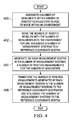
- FIG. 4 an illustration of a process for aligning a number of measurement systems to a reference coordinate system is depicted in the form of a flowchart in accordance with an illustrative embodiment.
- the process illustrated in Figure 4 may be implemented to align number of measurement systems 102 to reference coordinate system 150 in Figure 1 .
- Operation 400 may be performed by, for example, without limitation, mounting a set of monuments, such as set of monuments 132, to a monument structure on a robotic vehicle, such as monument structure 124 on robotic vehicle 120.
- number of robotic vehicles 118 with number of monuments 116 may be moved into environment 100 for use in aligning number of measurement systems 102 to reference coordinate system 150 (operation 402).
- number of position measurements 148 for number of monuments 116 may be generated by each measurement system in number of measurement systems 102 (operation 404).
- Number of position measurements 148 generated by each measurement system in number of measurement systems 102 may then be transformed to reference coordinate system 150 for use in aligning number of measurement systems 102 to reference coordinate system 150 (operation 406), with the process terminating thereafter.
- operation 406 Once operation 406 has been performed, all measurements 103 generated by number of measurement systems 102 may be processed with respect to the same coordinate system, such as reference coordinate system 150.
- each of number of measurement systems 102 may be moved and controlled within environment 100 using commands generated based on reference coordinate system 150.
- reference coordinate system 150 allows improved management of number of measurement systems 102 and may increase the speed and efficiency with which measurements 103 may be processed.
- FIG. 5 an illustration of a process for aligning a number of measurement systems to a reference coordinate system is depicted in the form of a flowchart in accordance with an illustrative embodiment.
- the process illustrated in Figure 5 may be implemented to align number of measurement systems 102 to reference coordinate system 150 in Figure 1 .
- the process may begin by mounting set of monuments 132 onto monument structure 124 of each robotic vehicle in number of robotic vehicles 118 (operation 500).
- number of robotic vehicles 118 may be moved to a number of optimal positions within environment 100 based on an optimization algorithm configured to identify the number of optimal positions that allow optimal calibration of number of monuments 116 mounted on number of robotic vehicles 118 to be achieved (operation 502).
- reference coordinate system 150 may be selected from one of a coordinate system for measurement system 146 in number of measurement systems 102 and a coordinate system for environment 100 (operation 504).
- Number of position measurements 148 for number of monuments 116 associated with number of robotic vehicles 118 may be generated by each measurement system in number of measurement systems 102 associated with number of robotic vehicles 118 (operation 506).
- Number of position measurements 148 generated by each measurement system in number of measurement systems 102 may then be sent to main controller 140 (operation 508).
- Main controller 140 may then transform number of position measurements 148 generated by each measurement system in number of measurement systems 102 to reference coordinate system 150 (operation 510). Thereafter, main controller 140 may align number of measurement systems 102 to reference coordinate system 150 such that all measurements 103 generated by number of measurement systems 102 may be generated relative to reference coordinate system 150 (operation 512), with the process terminating thereafter.
- Data processing system 600 may be used to implement main controller 140, one or more computers in computer system 142, control unit 130, and/or the control unit for a robotic vehicle in number of robotic vehicles 118 in Figure 1 .
- data processing system 600 includes communications framework 602, which provides communications between processor unit 604, storage devices 606, communications unit 608, input/output unit 610, and display 612.
- communications framework 602 may be implemented as a bus system.
- Processor unit 604 is configured to execute instructions for software to perform a number of operations.
- Processor unit 604 may comprise a number of processors, a multi-processor core, and/or some other type of processor, depending on the implementation.
- processor unit 604 may take the form of a hardware unit, such as a circuit system, an application specific integrated circuit (ASIC), a programmable logic device, or some other suitable type of hardware unit.
- ASIC application specific integrated circuit
- Storage devices 606 may be in communication with processor unit 604 through communications framework 602.
- a storage device also referred to as a computer readable storage device, is any piece of hardware capable of storing information on a temporary and/or permanent basis. This information may include, but is not limited to, data, program code, and/or other information.
- Memory 614 and persistent storage 616 are examples of storage devices 606.
- Memory 614 may take the form of, for example, a random access memory or some type of volatile or non-volatile storage device.
- Persistent storage 616 may comprise any number of components or devices.
- persistent storage 616 may comprise a hard drive, a flash memory, a rewritable optical disk, a rewritable magnetic tape, or some combination of the above.
- the media used by persistent storage 616 may or may not be removable.
- Communications unit 608 allows data processing system 600 to communicate with other data processing systems and/or devices. Communications unit 608 may provide communications using physical and/or wireless communications links.
- Input/output unit 610 allows input to be received from and output to be sent to other devices connected to data processing system 600.
- input/output unit 610 may allow user input to be received through a keyboard, a mouse, and/or some other type of input device.
- input/output unit 610 may allow output to be sent to a printer connected to data processing system 600.
- Display 612 is configured to display information to a user.
- Display 612 may comprise, for example, without limitation, a monitor, a touch screen, a laser display, a holographic display, a virtual display device, and/or some other type of display device.
- processor unit 604 may perform the processes of the different illustrative embodiments using computer-implemented instructions. These instructions may be referred to as program code, computer usable program code, or computer readable program code and may be read and executed by one or more processors in processor unit 604.
- program code 618 is located in a functional form on computer readable media 620, which is selectively removable, and may be loaded onto or transferred to data processing system 600 for execution by processor unit 604.
- Program code 618 and computer readable media 620 together form computer program product 622.
- computer readable media 620 may be computer readable storage media 624 or computer readable signal media 626.
- Computer readable storage media 624 is a physical or tangible storage device used to store program code 618 rather than a medium that propagates or transmits program code 618.
- Computer readable storage media 624 may be, for example, without limitation, an optical or magnetic disk or a persistent storage device that is connected to data processing system 600.
- program code 618 may be transferred to data processing system 600 using computer readable signal media 626.
- Computer readable signal media 626 may be, for example, a propagated data signal containing program code 618. This data signal may be an electromagnetic signal, an optical signal, and/or some other type of signal that can be transmitted over physical and/or wireless communications links.
- data processing system 600 in Figure 6 is not meant to provide architectural limitations to the manner in which the illustrative embodiments may be implemented.
- the different illustrative embodiments may be implemented in a data processing system that includes components in addition to or in place of those illustrated for data processing system 600. Further, components shown in Figure 6 may be varied from the illustrative examples shown.
- aircraft manufacturing and service method 700 may be described in the context of aircraft manufacturing and service method 700 as shown in Figure 7 and aircraft 800 as shown in Figure 8 .
- Figure 7 an illustration of an aircraft manufacturing and service method is depicted in the form of a block diagram in accordance with an illustrative embodiment.
- aircraft manufacturing and service method 700 may include specification and design 702 of aircraft 800 in Figure 8 and material procurement 704.
- aircraft 800 in Figure 8 During production, component and subassembly manufacturing 706 and system integration 708 of aircraft 800 in Figure 8 takes place. Thereafter, aircraft 800 in Figure 8 may go through certification and delivery 710 in order to be placed in service 712. While in service 712 by a customer, aircraft 800 in Figure 8 is scheduled for routine maintenance and service 714, which may include modification, reconfiguration, refurbishment, and other maintenance or service.
- Each of the processes of aircraft manufacturing and service method 700 may be performed or carried out by a system integrator, a third party, and/or an operator.
- the operator may be a customer.
- a system integrator may include, without limitation, any number of aircraft manufacturers and major-system subcontractors
- a third party may include, without limitation, any number of vendors, subcontractors, and suppliers
- an operator may be an airline, a leasing company, a military entity, a service organization, and so on.
- aircraft 800 is produced by aircraft manufacturing and service method 700 in Figure 7 and may include airframe 802 with plurality of systems 804 and interior 806.
- systems 804 include one or more of propulsion system 808, electrical system 810, hydraulic system 812, and environmental system 814. Any number of other systems may be included.
- propulsion system 808 electrical system 810, hydraulic system 812, and environmental system 814. Any number of other systems may be included.
- an aerospace example is shown, different illustrative embodiments may be applied to other industries, such as the automotive industry.
- Apparatuses and methods embodied herein may be employed during at least one of the stages of aircraft manufacturing and service method 700 in Figure 7 .
- monument system 114 from Figure 1 may be used for aligning measurement systems during any one of the stages of aircraft manufacturing and service method 700.
- monument system 114 from Figure 1 may be used during at least one of component and subassembly manufacturing 706, system integration 708, routine maintenance and service 714, or some other stage of aircraft manufacturing and service method 700.
- components or subassemblies produced in component and subassembly manufacturing 706 in Figure 7 may be fabricated or manufactured in a manner similar to components or subassemblies produced while aircraft 800 is in service 712 in Figure 7 .
- one or more apparatus embodiments, method embodiments, or a combination thereof may be utilized during production stages, such as component and subassembly manufacturing 706 and system integration 708 in Figure 7 .
- One or more apparatus embodiments, method embodiments, or a combination thereof may be utilized while aircraft 800 is in service 712 and/or during maintenance and service 714 in Figure 7 .
- the use of a number of the different illustrative embodiments may substantially expedite the assembly of and/or reduce the cost of aircraft 800.
- each block in the flowcharts or block diagrams may represent a module, a segment, a function, and/or a portion of an operation or step.
- the function or functions noted in the blocks may occur out of the order noted in the figures.
- two blocks shown in succession may be executed substantially concurrently, or the blocks may sometimes be performed in the reverse order, depending upon the functionality involved.
- other blocks may be added in addition to the illustrated blocks in a flowchart or block diagram.
Landscapes
- Engineering & Computer Science (AREA)
- Physics & Mathematics (AREA)
- General Physics & Mathematics (AREA)
- Automation & Control Theory (AREA)
- Remote Sensing (AREA)
- Aviation & Aerospace Engineering (AREA)
- Radar, Positioning & Navigation (AREA)
- Quality & Reliability (AREA)
- Manufacturing & Machinery (AREA)
- General Engineering & Computer Science (AREA)
- Length Measuring Devices By Optical Means (AREA)
- Length Measuring Devices With Unspecified Measuring Means (AREA)
- Control Of Position, Course, Altitude, Or Attitude Of Moving Bodies (AREA)
- Optics & Photonics (AREA)
- Electromagnetism (AREA)
Abstract
Description
- The present disclosure relates generally to monuments used by metrology systems and, in particular, to monuments that are mounted on robots. Still more particularly, the present disclosure relates to a method and apparatus for tracking mobile reference points using a robotic-mounted monument system.
- Monuments may often be used in environments in which metrology systems are used. A metrology system may be any system configured to generate measurements for one or more parameters. Examples of metrology systems may include, but are not limited to, optical measuring systems, motion capture systems, laser tracking systems, imaging systems, radar systems, global positioning systems, thermal imaging systems, and other types of sensor systems.
- As used herein, a "monument" for a metrology system may be a rigid structure that may be used as a reference point by the metrology system. A monument used for a metrology system may also be referred to as a metrology monument. Metrology monuments for a metrology system may need to be located such that there is a clear line-of-sight between the metrology monuments and the metrology system.
- Typically, metrology monuments may be placed at fixed locations within the area in which the metrology system is to be used. The area may be, for example, without limitation, a manufacturing area, a testing area, an assembly area, or some other type of area. However, in some situations, the locations in which these metrology monuments are placed may limit the clear line of sight between the metrology monuments and the metrology system.
- As one illustrative example, a flexible manufacturing environment may use automated guided vehicles (AGV's) to transport large aerospace structures along a factory assembly line. The automated guided vehicles may require that the surfaces on which these vehicles move be substantially flat, smooth, and free of obstructions. Consequently, within this type of environment, the potential locations at which metrology monuments may be placed may be limited to locations on the sides of the work area. These locations may not always provide the clear lines of sight needed between a metrology system and the metrology monuments.
- Some currently available metrology monuments may be placed on mobile platforms such as, for example, without limitation, roll carts. These metrology monuments may then be manually rolled out into the work area when needed by a metrology system and manually rolled out of the work area when not needed by the metrology system. In this manner, the metrology system may be stored out of the way until needed.
- However, manually moving the metrology monuments in and out of the work area may pose safety concerns for the workers moving the metrology monuments. In particular, work environments such as, for example, without limitation, highly automated factory environments, may present safety issues for workers. Therefore, it would be desirable to have a method and apparatus that take into account at least some of the issues discussed above, as well as other possible issues.
- In one illustrative example, an apparatus may comprise a number of robotic vehicles and a number of monuments associated with the number of robotic vehicles. The number of robotic vehicles may be configured to move into an environment.
- In another illustrative embodiment, a monument system for use with a number of measurement systems in a flexible manufacturing environment may comprise a number of monuments, a number of robotic vehicles, and a main controller. Each measurement system in the number of measurement systems in the flexible manufacturing environment may be configured to generate a number of position measurements for the number of monuments for use in aligning the number of measurement systems to a reference coordinate system. A monument in the number of monuments may be selected from one of a sensor device, a number of sensor devices, a target, and a rigid structure. The number of robotic vehicles may be configured to move into an environment. A robotic vehicle in the number of robotic vehicles may comprise a base, a monument structure removably associated with the base, a movement system associated with the base, a sensor system associated with the base, and a control unit associated with the base. The monument structure may be configured to support and hold a set of monuments in the number of monuments. The monument structure may comprise a positioning system configured to at least one of position or orient a monument in the set of monuments relative to the base. The movement system may be configured to move the robotic vehicle. The sensor system may be configured to generate sensor data. The control unit may be configured to receive the sensor data. The control unit may use the sensor data to control the movement system. The main controller may be configured to transform a number of position measurements generated by each of the number of measurement systems to a reference coordinate system to align the number of measurement systems to the reference coordinate system.
- In yet another illustrative example, a method for aligning a number of measurement systems to a reference coordinate system may be provided. A number of monuments may be associated with a number of robotic vehicles configured to move within an environment. The number of robotic vehicles may be moved with the number of monuments into the environment for use in aligning the number of measurement systems to the reference coordinate system.
- In still yet another illustrative embodiment, a method for aligning a number of measurement systems to a reference coordinate system may be provided. The reference coordinate system may be selected from one of a coordinate system for a measurement system in the number of measurement systems and a coordinate system for an environment. A number of robotic vehicles having a number of monuments associated with the number of robotic vehicles may be moved into a number of optimal positions within a flexible manufacturing environment based on an optimization algorithm configured to identify the number of optimal positions that allow optimal calibration of the number of monuments to be achieved. A number of position measurements generated by each measurement system in the number of measurement systems positioned in the environment may be transformed to the reference coordinate system for use in aligning the number of measurement systems to the reference coordinate system. A monument structure holding a set of monuments in the number of monuments on a robotic vehicle in the number of robotic vehicles may be removed to at least one of add a monument, remove a monument, and replace a monument in the set of monuments. The number of robotic vehicles may be moved out of the environment when the number of measurement systems have completed generating measurements for a number of objects on which operations are being performed within the environment.
- In summary, according to one aspect there is provided an apparatus including a number of robotic vehicles (118) configured to move into an environment (100); and a number of monuments (116) associated with the number of robotic vehicles (118).
- Optionally, the apparatus further including a number of measurement systems (102) in the environment (100), wherein each of the number of measurement systems (102) is configured to generate a number of position measurements (148) for the number of monuments (116) for use in aligning the number of measurement systems (102) to a reference coordinate system (150).
- Optionally, the apparatus wherein the number of position measurements (148) are used to align the number of measurement systems (102) to the reference coordinate system (150) such that measurements (103) generated by the number of measurement systems (102) may be processed according to the reference coordinate system (150).
- Optionally, the apparatus further including a main controller (140) configured to transform the number of position measurements (148) generated by each of the number of measurement systems (102) to the reference coordinate system (150) to align the number of measurement systems (102) to the reference coordinate system (150).
- Optionally, the apparatus wherein the number of measurement systems (102) includes at least one of an optical measurement system (104), a laser tracking device (106), a position tracking system (108), an imaging system (110), and a motion capture system (112).
- Optionally, the apparatus wherein the reference coordinate system (150) is selected from one of a coordinate system for a measurement system in the number of measurement systems (102) and a coordinate system for the environment (100).
- Optionally, the apparatus wherein a robotic vehicle (120) in the number of robotic vehicles (118) includes a base (122); and a monument structure (124) removably associated with the base (122), wherein the monument structure (124) is configured to support and hold a set of monuments (132) in the number of monuments (116).
- Optionally, the apparatus wherein the monument structure (124) includes a positioning system (144) configured to at least one of position or orient a monument in the set of monuments (132) relative to the base (122).
- Optionally, the apparatus wherein the robotic vehicle (120) further includes a movement system (126) associated with the base (122) and configured to move the robotic vehicle (120); a sensor system (128) associated with the base (122) and configured to generate sensor data (138); and a control unit (130) associated with the base (122) and configured to receive the sensor data (138), wherein the control unit (130) uses the sensor data (138) to control the movement system (126).
- Optionally, the apparatus wherein the movement system (126) is a holonomic movement system (135).
- Optionally, the apparatus wherein a monument in the number of monuments (116) is selected from one of a sensor device, a number of sensor devices, a target, and a rigid structure.
- Optionally, the apparatus wherein the number of robotic vehicles (118) and the number of monuments (116) form a monument system (114).
- Optionally, the apparatus wherein the environment (100) is a flexible manufacturing environment.
- According to another aspect there is provided a monument system (114) for use with a number of measurement systems (102) in a flexible manufacturing environment, the monument system (114) including a number of monuments (116) in which each measurement system in the number of measurement systems (102) in the flexible manufacturing environment is configured to generate a number of position measurements (148) for the number of monuments (116) for use in aligning the number of measurement systems (102) to a reference coordinate system (150) and in which a monument in the number of monuments (116) is selected from one of a sensor device, a number of sensor devices, a target, and a rigid structure; a number of robotic vehicles (118) configured to move into an environment (100) in which a robotic vehicle (120) in the number of robotic vehicles (118) includes a base (122); a monument structure (124) removably associated with the base (122) in which the monument structure (124) is configured to support and hold a set of monuments (132) in the number of monuments (116) and in which the monument structure (124) comprises a positioning system (144) configured to at least one of position or orient a monument in the set of monuments (132) relative to the base (122); a movement system (126) associated with the base (122) and configured to move the robotic vehicle (120); a sensor system (128) associated with the base (122) and configured to generate sensor data (138); and a control unit (130) associated with the base (122) and configured to receive the sensor data (138), wherein the control unit (130) uses the sensor data (138) to control the movement system (126); and a main controller (140) configured to transform the number of position measurements (148) generated by each of the number of measurement systems (102) to the reference coordinate system (150) to align the number of measurement systems (102) to the reference coordinate system (150).
- According to yet another aspect there is provided a method for aligning a number of measurement systems (102) to a reference coordinate system (150), the method including associating a number of monuments (116) with a number of robotic vehicles (118) configured to move within an environment (100); and moving the number of robotic vehicles (118) with the number of monuments (116) into the environment (100) for use in aligning the number of measurement systems (102) to the reference coordinate system (150).
- Optionally, the method further including generating, by each measurement system in the number of measurement systems (102), a number of position measurements (148) for the number of monuments (116).
- Optionally, the method further including transforming (402) the number of position measurements (148) generated by the each measurement system in the number of measurement systems (102) to the reference coordinate system (150) for use in aligning the number of measurement systems (102) to the reference coordinate system (150).
- Optionally, the method wherein aligning the number of measurement systems (102) to the reference coordinate system (150) allows measurements (103) generated by each of the number of measurement systems (102) to be processed with respect to the reference coordinate system (150).
- Optionally, the method further including selecting (504) the reference coordinate system (150) from one of a coordinate system for a measurement system (146) in the number of measurement systems (102) and a coordinate system for the environment (100).
- Optionally, the method wherein moving the number of robotic vehicles (118) into the environment (100) includes moving the number of robotic vehicles (118) with the number of monuments (116) to a number of optimal positions (141) within the environment (100).
- Optionally, the method wherein moving the number of robotic vehicles (118) with the number of monuments (116) to the number of optimal positions (141) within the environment (100) includes moving (502) the number of robotic vehicles (118) to the number of optimal positions (141) within the environment (100) based on an optimization algorithm (139) configured to identify the number of optimal positions (141) that allow optimal calibration of the number of monuments (116) to be achieved.
- Optionally, the method wherein associating the number of monuments (116) with the number of robotic vehicles (118) includes mounting a set of monuments (132) in the number of monuments (116) on a monument structure (124) on a robotic vehicle in the number of robotic vehicles (118).
- Optionally, the method further including changing a position of a monument in the set of monuments (132) relative to the monument structure (124) on the robotic vehicle.
- Optionally, the method further including changing an orientation of a monument in the set of monuments (132) relative to the monument structure (124) on the robotic vehicle.
- Optionally, the method further including removing the monument structure (124) holding the set of monuments (132) in the number of monuments (116) on a robotic vehicle (120) in the number of robotic vehicles (118) to at least one of add a monument to, remove a monument from, or replace a monument in the set of monuments (132) mounted on the monument structure (124).
- Optionally, the method further including moving the number of robotic vehicles (118) with the number of monuments (116) out of the environment (100) when the number of measurement systems (102) have completed generating measurements (103) for a number of objects on which operations are being performed within the environment (100).
- According to still another aspect there is provided a method for aligning a number of measurement systems (102) to a reference coordinate system (150), the method including selecting (504) the reference coordinate system (150) from one of a coordinate system for a measurement system (146) in the number of measurement systems (102) and a coordinate system for an environment (100); moving a number of robotic vehicles (118) having a number of monuments (116) associated with the number of robotic vehicles (118) into a number of optimal positions (141) within a flexible manufacturing environment based on an optimization algorithm (139) configured to identify the number of optimal positions (141) that allow optimal calibration of the number of monuments (116) to be achieved; transforming a number of position measurements (148) generated by each measurement system in the number of measurement systems (102) positioned in the environment (100) to the reference coordinate system (150) for use in aligning the number of measurement systems (102) to the reference coordinate system (150); removing a monument structure (124) holding a set of monuments (132) in the number of monuments (116) on a robotic vehicle (120) in the number of robotic vehicles (118) to at least one of add a monument, remove a monument, and replace a monument in the set of monuments (132); and moving the number of robotic vehicles (118) out of the environment (100) when the number of measurement systems (102) have completed generating measurements (103) for a number of objects on which operations are being performed within the environment (100).
- The features and functions can be achieved independently in various embodiments of the present disclosure or may be combined in yet other embodiments in which further details can be seen with reference to the following description and drawings.
- The novel features believed characteristic of the illustrative embodiments are set forth in the appended claims. The illustrative embodiments, however, as well as a preferred mode of use, further objectives and features thereof, will best be understood by reference to the following detailed description of an illustrative embodiment of the present disclosure when read in conjunction with the accompanying drawings, wherein:
-
Figure 1 is an illustration of an environment in which a number of measurement systems are used in the form of a block diagram in accordance with an illustrative embodiment; -
Figure 2 is an illustration of a robotic vehicle in accordance with an illustrative embodiment; -
Figure 3 is an illustration of an environment in which a number of measurement systems are used to generate measurements in accordance with an illustrative embodiment; -
Figure 4 is an illustration of a process for aligning a number of measurement systems to a reference coordinate system in the form of a flowchart in accordance with an illustrative embodiment; -
Figure 5 is an illustration of a process for aligning a number of measurement systems to a reference coordinate system in the form of a flowchart in accordance with an illustrative embodiment; -
Figure 6 is an illustration of a data processing system in the form of a block diagram in accordance with an illustrative embodiment; -
Figure 7 is an illustration of an aircraft manufacturing and service method in the form of a block diagram in accordance with an illustrative embodiment; and -
Figure 8 is an illustration of an aircraft in the form of a block diagram in which an illustrative embodiment may be implemented. - The illustrative embodiments recognize and take into account different considerations. For example, the illustrative embodiments recognize and take into account that it may be desirable to have an automated system for moving metrology monuments in and out of work areas that does not require human operators. In particular, the illustrative embodiments recognize and take into account that it may be beneficial to mount metrology monuments onto robotic vehicles.
- Thus, the illustrative embodiments provide a method and apparatus for using metrology monuments to align measurement systems. In another illustrative example, a method for aligning a number of measurement systems to a reference coordinate system may be provided. A number of robotic vehicles may be moved into an environment. A number of monuments may be associated with the number of robotic vehicles. A number of position measurements generated by each measurement system in the number of measurement systems positioned in the environment may be transformed to the reference coordinate system for use in aligning the number of measurement systems to the reference coordinate system.
- Referring now to the figures and, in particular, with reference to
Figure 1 , an illustration of an environment in which a number of measurement systems are used is depicted in the form of a block diagram in accordance with an illustrative embodiment. In this illustrative example,environment 100 may be an environment in which number ofmeasurement systems 102 may be used. - As used herein, a "number of" items may be one or more items. In this manner, number of
measurement systems 102 may include one or more measurement systems. Number ofmeasurement systems 102 may be configured to generatemeasurements 103 withinenvironment 100.Measurements 103 may be measurements for a number of objects on which operations are being performed withinenvironment 100. These operations may include, for example, without limitation, testing operations, drilling operations, assembly operations, fabrication operations, inspection operations, imaging operations, rework operations, and/or other types of operations. -
Environment 100 may take a number of different forms, depending on the implementation.Environment 100 may take the form of, for example, without limitation, a factory area, a work cell in a flexible manufacturing environment, a manufacturing area, an outdoor environment, an area inside of a building, a laboratory, a testing environment, a section of highway, a region of airspace, a region of space, an underwater environment, a storage area, an airport, or some other type of environment. - In this illustrative example, a measurement system in number of
measurement systems 102 may be any type of system or device configured to generate measurements for one or more parameters. In some cases, a measurement system in number ofmeasurement systems 102 may be referred to as a metrology system. - Number of
measurement systems 102 may include any number of different types of measurement systems. Number ofmeasurement systems 102 may include at least one of, for example, without limitation,optical measurement system 104,laser tracking device 106,position tracking system 108,imaging system 110,motion capture system 112, or some other type of measurement system or device. In this illustrative example,position tracking system 108 may take the form of one of a global positioning system that uses a satellite network, an optical positioning system, a magnetic positioning system, a large scale tracking system, or some other type of position tracking system. - As used herein, the phrase "at least one of," when used with a list of items, means different combinations of one or more of the listed items may be used and only one of the items in the list may be needed. The item may be a particular object, thing, or category. In other words, "at least one of" means any combination of items or number of items may be used from the list, but not all of the items in the list may be required.
- For example, "at least one of item A, item B, and item C" may mean item A; item A and item B; item B; item A, item B, and item C; or item B and item C. In some cases, "at least one of item A, item B, and item C" may mean, for example, without limitation, two of item A, one of item B, and ten of item C; four of item B and seven of item C; or some other suitable combination.
- Depending on the implementation, a measurement system in number of
measurement systems 102 may be configured to be stationary withinenvironment 100 or mobile. For example, without limitation, a measurement system in number ofmeasurement systems 102 may be associated with either a stationary platform or a mobile platform. - In this illustrative example,
monument system 114 may be configured for use with number ofmeasurement systems 102.Monument system 114 may be used to provide reference points formeasurements 103 generated by number ofmeasurement systems 102. - As depicted,
monument system 114 may include number ofmonuments 116 and number ofrobotic vehicles 118. As used herein, a "monument," such as one of number ofmonuments 116, may be any object that may be used to provide a reference point for at least one of number ofmeasurement systems 102. A monument may take the form of a sensor device, a number of sensor devices, a target, a rigid structure, or some other type of object. - Number of
monuments 116 may be configured for association with number ofrobotic vehicles 118. Depending on the implementation, one or more of number ofmonuments 116 may be mounted on each of number ofrobotic vehicles 118. As used herein, a "robotic vehicle," such as one of number ofrobotic vehicles 118, may be any type of mobile platform that may be configured to move either autonomously or semi-autonomously. -
Robotic vehicle 120 may be an example of one of number ofrobotic vehicles 118. In some cases,robotic vehicle 120 may be referred to as a monubot.Robotic vehicle 120 may includebase 122,monument structure 124,movement system 126,sensor system 128, andcontrol unit 130. -
Base 122 may be, for example, without limitation, the primary structural framework ofrobotic vehicle 120.Monument structure 124,movement system 126,sensor system 128, andcontrol unit 130 may be configured for association withbase 122. Depending on the implementation, one or more ofmonument structure 124,movement system 126,sensor system 128, andcontrol unit 130 may be removably associated withbase 122. - As used herein, when one component is "associated" with another component, the association is a physical association in the depicted examples. For example, a first component, such as
monument structure 124, may be considered to be associated with a second component, such asbase 122, by being secured to the second component, bonded to the second component, mounted to the second component, welded to the second component, fastened to the second component, and/or connected to the second component in some other suitable manner. The first component also may be connected to the second component using a third component. Further, the first component may be considered to be associated with the second component by being formed as part of and/or as an extension of the second component. - A first component may be removably associated with a second component when the first component is attached to the second component and then removed from the second component. In some cases, the first component may then be reattached to the second component.
- In this illustrative example,
monument structure 124 may be configured to hold and support set ofmonuments 132 in number ofmonuments 116. As used herein, a "set of" items may be one or more items. In this manner, set ofmonuments 132 may include one or more monuments. -
Movement system 126 may be used to moverobotic vehicle 120 withinenvironment 100.Movement system 126 may include number ofmovement devices 134. Number ofmovement devices 134 may include, for example, without limitation, at least one of a wheel, a holonomic wheel, a roller, a slider, an air bearing, a spherical bearing, or some other type of movement device. - A holonomic wheel may be an omnidirectional wheel. In other words, a holonomic wheel may be configured to move in any direction within about 360 degrees. When number of
movement devices 134 includes a number of holonomic wheels,movement system 126 may be referred to asholonomic movement system 135.Holonomic movement system 135 may include other components in addition to number ofmovement devices 134. For example, without limitation,holonomic movement system 135 may include any number of drive motors, batteries, control units, and/or other components. - In this illustrative example,
sensor system 128 may include number ofsensor devices 136. Number ofsensor devices 136 may include at least one of, for example, without limitation, a navigation sensor, a position tracking device, an imaging sensor, a two-dimensional laser scanner, a three-dimensional laser scanner, or some other type of sensor device.Sensor system 128 may be configured to generatesensor data 138 that may be used to navigaterobotic vehicle 120 withinenvironment 100. -
Control unit 130 may be implemented using hardware, software, or a combination of the two. In one illustrative example,control unit 130 may be implemented in the form of a processor unit. Of course, in other illustrative examples,control unit 130 may be implemented using at least one of a computer system, a number of computers in communication with each other, a microprocessor, an integrated circuit, an electronic circuit, or some other type of processor. - In some illustrative examples, all of
control unit 130 may be implemented onrobotic vehicle 120. In other illustrative examples, a portion ofcontrol unit 130 may be implemented remotely. For example, without limitation, a portion ofcontrol unit 130 may be implemented within a computer in a location remote torobotic vehicle 120. -
Control unit 130 may be configured to communicate withsensor system 128. In particular,control unit 130 may be configured to receivesensor data 138 fromsensor system 128. In some cases,control unit 130 may also be configured to controlsensor system 128. - In this illustrative example,
control unit 130 may usesensor data 138 to control the movement ofrobotic vehicle 120 withinenvironment 100. For example, without limitation,control unit 130 may usesensor data 138 to controlmovement system 126. In particular,control unit 130 may control number ofmovement devices 134 to moverobotic vehicle 120 withinenvironment 100. - Each robotic vehicle in number of
robotic vehicles 118 may be implemented in a manner similar torobotic vehicle 120. In this manner, each of number ofrobotic vehicles 118 may be configured to have a base, a monument structure, a movement system, a sensor system, and a control unit similar tobase 122,monument structure 124,movement system 126,sensor system 128, andcontrol unit 130, respectively. - In some illustrative examples, the control unit on each robotic vehicle in number of
robotic vehicles 118 may be configured to communicate with the other control units on the other robotic vehicles in number ofrobotic vehicles 118. In this manner, these control units may be able to coordinate the movement of number ofrobotic vehicles 118 withinenvironment 100. In particular, these control units may be able to coordinate the movement of number ofrobotic vehicles 118 withinenvironment 100. - In other illustrative examples, the control unit on each robotic vehicle in number of
robotic vehicles 118 may be configured to operate independently of the other control units. For example,control unit 130 onrobotic vehicle 120 may usesensor data 138 obtained fromsensor system 128 to track the positions of other robotic vehicles in number ofrobotic vehicles 118 withinenvironment 100. - Further, in some cases, the control unit on each robotic vehicle in number of
robotic vehicles 118 may be configured to communicate withmain controller 140. Number ofrobotic vehicles 118 may communicate withmain controller 140 wirelessly in these examples.Main controller 140 may be a primary controller withinenvironment 100.Main controller 140 may be configured to control operations performed withinenvironment 100. -
Main controller 140 may be configured to communicate with and/or control number ofmeasurement systems 102. In some cases,main controller 140 may be configured to communicate and/or control number ofrobotic vehicles 118. - Depending on the implementation,
main controller 140 may be implemented using hardware, software, or a combination of the two. In one illustrative example,main controller 140 may be implemented usingcomputer system 142.Computer system 142 may be comprised of one or more computers. When more than one computer is present incomputer system 142, these computers may be in communication with each other. - In this illustrative example, prior to number of
measurement systems 102 being used to generatemeasurements 103 withinenvironment 100, number ofrobotic vehicles 118 carrying number ofmonuments 116 may be moved intoenvironment 100. Each of number ofrobotic vehicles 118 may be moved into a position withinenvironment 100 that allows for optimal calibration of the set of monuments mounted on the monument structure of each of number ofrobotic vehicles 118. In particular, the control unit on each of number ofrobotic vehicles 118 may useoptimization algorithm 139 to identify number ofoptimal positions 141 that may provide optimal calibration of the set of monuments mounted on the robotic vehicle. - Optimal calibration of the set of monuments mounted on the robotic vehicle may be achieved when a number of selected factors are taken into account.
Optimization algorithm 139 may be configured to take these selected factors into account. One factor may be the actual number of robotic vehicles in number ofrobotic vehicles 118 that are needed. Another factor may be the largest common floor area that is within the working range of all of number ofmeasurement systems 102. In other words, the largest common area within which all of number ofmeasurement systems 102 may move and/or perform operations may be taken into account. - Yet another factor may be that the position of each robotic vehicle in number of
robotic vehicles 118 may need to allow the robotic vehicle to be spatially oriented such that any measurement system in number ofmeasurement systems 102 that includes one or more direction-dependent sensors may need to be able to point at the robotic vehicle. Of course, depending on the implementation, other factors may be taken into account in identifying number ofoptimal positions 141. In one illustrative example,optimization algorithm 139 may take the form of a global cost function optimization that uses a least-squares minimization. - Of course, in some illustrative examples,
main controller 140 may be configured to control the movement of each of number ofrobotic vehicles 118.Main controller 140 may be configured to wirelessly send commands to number ofrobotic vehicles 118. For example, without limitation,main controller 140 may be configured to wirelessly receivesensor data 138 fromsensor system 128 and/orcontrol unit 130 onboardrobotic vehicle 120.Main controller 140 may usesensor data 138 along with the sensor data received from the other robotic vehicles in number ofrobotic vehicles 118 to guide number ofrobotic vehicles 118 to the optimal positions withinenvironment 100. - In some illustrative examples, once each of number of
robotic vehicles 118 has been moved to the optimal position, the monument structure on each robotic vehicle may be used to control the position and/or orientation of each monument mounted on the robotic vehicle. For example, without limitation,monument structure 124 may havepositioning system 144 configured to adjust the position and/or orientation of each monument in set ofmonuments 132 relative tomonument structure 124. - Thereafter, each measurement system in number of
measurement systems 102 may be configured to measure the position of each monument in number ofmonuments 116 with respect to a coordinate system for that measurement system. -
Measurement system 146 may be an example of one of number ofmeasurement systems 102.Measurement system 146 may be configured to generate number ofposition measurements 148 and send number ofposition measurements 148 tomain controller 140. Number ofposition measurements 148 may include a position measurement for each of number ofmonuments 116. -
Main controller 140 may be configured to transform number ofposition measurements 148 to reference coordinatesystem 150. Further,main controller 140 may be configured to transform the position measurements generated by each of number ofmeasurement systems 102 to reference coordinatesystem 150. - In one illustrative example, reference coordinate
system 150 may be three-dimensional reference coordinatesystem 152. In some cases, reference coordinatesystem 150 may be selected as the coordinate system used by a particular measurement in number ofmeasurement systems 102. In other illustrative examples, reference coordinatesystem 150 may be a coordinate system forenvironment 100. In still other examples, reference coordinatesystem 150 may be the coordinate system for an object on which one or more operations are being performed inenvironment 100. -
Main controller 140 may transform number ofposition measurements 148 to reference coordinatesystem 150 using, for example, without limitation, currently available mathematical formulas and/or techniques. In this manner, all measurements generated bymeasurement system 146 may then be transformed to reference coordinatesystem 150. Thus,measurement system 146 may be considered aligned with respect to reference coordinatesystem 150.Main controller 140 may be configured to align each of number ofmeasurement systems 102 with reference coordinatesystem 150 using number ofmonuments 116. - Once number of
measurement systems 102 has been aligned to reference coordinatesystem 150,measurements 103 may then be generated for the number of objects on which operations are being performed inenvironment 100. Further, number ofrobotic vehicles 118 may then be moved out ofenvironment 100 or at least out of the way of number ofmeasurement systems 102 and/or other tools or machines inenvironment 100. Number ofrobotic vehicles 118 may be moved away before or aftermeasurements 103 are generated, depending on the implementation. - In some cases, one or more of number of
robotic vehicles 118 may be moved back intoenvironment 100 to ensure that number ofmeasurement systems 102 are still properly aligned with reference coordinatesystem 150. In this manner, number ofrobotic vehicles 118 may be moved into a work area inenvironment 100 when needed and stored out of the way when not needed. - Further, when the operations being performed on a particular object in
environment 100 have been completed, the object may be moved out ofenvironment 100. A different object may then be brought intoenvironment 100. In some cases, the particular monuments included in number ofmonuments 116 may be changed. For example, at least one monument may be added to number ofmonuments 116, removed from number ofmonuments 116, or replaced in number ofmonuments 116. - The illustration of
environment 100 inFigure 1 is not meant to imply physical or architectural limitations to the manner in which an illustrative embodiment may be implemented. Other components in addition to or in place of the ones illustrated may be used. Some components may be optional. Also, the blocks are presented to illustrate some functional components. One or more of these blocks may be combined, divided, or combined and divided into different blocks when implemented in an illustrative embodiment. - With reference now to
Figure 2 , an illustration of a robotic vehicle is depicted in accordance with an illustrative embodiment. In this illustrative example,robotic vehicle 200 may be an example of one implementation forrobotic vehicle 120 inFigure 1 . - As depicted,
robotic vehicle 200 may includebase 202,monument structure 204,movement system 206,sensor system 208, andcontrol unit 210.Base 202,monument structure 204,movement system 206,sensor system 208, andcontrol unit 210 may be examples of implementations forbase 122,monument structure 124,movement system 126,sensor system 128, andcontrol unit 130, respectively, inFigure 1 . In this illustrative example,monument structure 204,movement system 206,sensor system 208, andcontrol unit 210 may be attached tobase 202. Further,monument structure 204 may be removably attached tobase 202. - In this illustrative example,
monument 212 andmonument 214 may be attached tomonument structure 204.Monument 212 andmonument 214 may be an example of one implementation for set ofmonuments 132 inFigure 1 .Monument structure 204 may have a positioning system (not shown) that may allowmonument 212 andmonument 214 to be repositioned and/or reoriented relative tobase 202. - For example, without limitation,
monument structure 204 may be configured to movemonument 212 and/ormonument 214 in a direction substantially parallel toaxis 216 to reposition these monuments. Further, in some cases,monument structure 204 may be configured to rotatemonument 212 and/ormonument 214 aboutaxis 216 in a direction alongarrow 218 to reorient these monuments. - As depicted,
movement system 206 may includeholonomic wheel 220,holonomic wheel 222,motor 224, andbattery 226.Holonomic wheel 220 andholonomic wheel 222 may be an example of one implementation for number ofmovement devices 134 inFigure 1 . - In this illustrative example,
sensor system 208 may includelaser scanner 228.Laser scanner 228 may be an example of one implementation for number ofsensor devices 136 inFigure 1 . In this illustrative example,laser scanner 228 may be a two-dimensional laser scanner.Laser scanner 228 may generate sensor data and then send this sensor data to controlunit 210.Control unit 210 may be configured to use this sensor data to control the movement ofrobotic vehicle 200. For example, without limitation,control unit 210 may send commands tomovement system 206 based on the sensor data. - With reference now to
Figure 3 , an illustration of an environment in which a number of measurement systems are used to generate measurements is depicted in accordance with an illustrative embodiment. In this illustrative example,environment 300 may be an example of one implementation forenvironment 100 inFigure 1 . - As depicted, number of
measurement systems 302 may be present withinenvironment 300. Number ofmeasurement systems 302 may be an example of one implementation for number ofmeasurement systems 102 inFigure 1 . Number ofmeasurement systems 302 may includelaser tracking system 304,motion capture system 306,laser radar system 308, andposition tracking system 310. - Further,
monument system 312 may also be present withinenvironment 300.Monument system 312 may includerobotic vehicle 314holding monument 315 andmonument 316,robotic vehicle 318holding monument 320 andmonument 322, androbotic vehicle 324holding monument 326 andmonument 328.Robotic vehicles robotic vehicles 118 inFigure 1 . Further,monuments monuments 116 inFigure 1 . - As depicted,
main controller 329 may also be present withinenvironment 300. In this illustrative example, onlylaser tracking system 304 andposition tracking system 310 may be currently activated for use.Laser tracking system 304 may be configured to communicate withmain controller 329 over wireless communications link 330.Position tracking system 310 may be configured to communicate withmain controller 329 over wireless communications link 332. Further,robotic vehicles main controller 329 overwireless communications links - In this illustrative example,
robotic vehicles environment 300 such thatmonuments robotic vehicles laser tracking system 304 andposition tracking system 310 may generate a position measurement for each of robotic vehicles 314,318, and 324. - In particular,
laser tracking system 304 may generate a position measurement for each of robotic vehicles 314,318, and 324, as indicated bylines position tracking system 310 may generate a position measurement for each ofrobotic vehicles lines main controller 329 for processing. -
Main controller 329 may be configured to transform these position measurements to a reference coordinate system (not shown), similar to reference coordinatesystem 150 inFigure 1 . In this manner,main controller 329 may alignlaser tracking system 304 andposition tracking system 310 to the reference coordinate system (not shown) such that all measurements generated by these measurement systems may be generated relative to the reference coordinate system (not shown). - As one illustrative example,
laser tracking system 304 may be used to measure the position of an assembly (not shown) withinenvironment 300.Position tracking system 310 may be used to measure the position of a part (not shown) that is to be placed on this assembly withinenvironment 300.Main controller 329 may identify the transformation needed to transform the position measurements oflaser tracking system 304 and ofposition tracking system 310 to the reference coordinate system (not shown) such that these systems are mathematically aligned with respect to the reference coordinate system (not shown). For example, without limitation, the movement command required to place the part on the assembly may be calculated using the transformation identified bymain controller 329. The movement command may then be used to, for example, without limitation, command a robot (not shown) located withinenvironment 300 to place the part on the assembly. - The illustrations of
robotic vehicle 200 inFigure 2 andenvironment 300 inFigure 3 are not meant to imply physical or architectural limitations to the manner in which an illustrative embodiment may be implemented. Other components in addition to or in place of the ones illustrated may be used. Some components may be optional. - The different components shown in
Figures 2-3 may be illustrative examples of how components shown in block form inFigure 1 can be implemented as physical structures. Additionally, some of the components inFigures 2-3 may be combined with components inFigure 1 , used with components inFigure 1 , or a combination of the two. - With reference now to
Figure 4 , an illustration of a process for aligning a number of measurement systems to a reference coordinate system is depicted in the form of a flowchart in accordance with an illustrative embodiment. The process illustrated inFigure 4 may be implemented to align number ofmeasurement systems 102 to reference coordinatesystem 150 inFigure 1 . - The process may begin by associating number of
monuments 116 with number ofrobotic vehicles 118 configured to move within environment 100 (operation 400).Operation 400 may be performed by, for example, without limitation, mounting a set of monuments, such as set ofmonuments 132, to a monument structure on a robotic vehicle, such asmonument structure 124 onrobotic vehicle 120. - Thereafter, number of
robotic vehicles 118 with number ofmonuments 116 may be moved intoenvironment 100 for use in aligning number ofmeasurement systems 102 to reference coordinate system 150 (operation 402). Next, number ofposition measurements 148 for number ofmonuments 116 may be generated by each measurement system in number of measurement systems 102 (operation 404). - Number of
position measurements 148 generated by each measurement system in number ofmeasurement systems 102 may then be transformed to reference coordinatesystem 150 for use in aligning number ofmeasurement systems 102 to reference coordinate system 150 (operation 406), with the process terminating thereafter. Onceoperation 406 has been performed, allmeasurements 103 generated by number ofmeasurement systems 102 may be processed with respect to the same coordinate system, such as reference coordinatesystem 150. - Further, each of number of
measurement systems 102 may be moved and controlled withinenvironment 100 using commands generated based on reference coordinatesystem 150. Using reference coordinatesystem 150 allows improved management of number ofmeasurement systems 102 and may increase the speed and efficiency with whichmeasurements 103 may be processed. - With reference now to
Figure 5 , an illustration of a process for aligning a number of measurement systems to a reference coordinate system is depicted in the form of a flowchart in accordance with an illustrative embodiment. The process illustrated inFigure 5 may be implemented to align number ofmeasurement systems 102 to reference coordinatesystem 150 inFigure 1 . - The process may begin by mounting set of
monuments 132 ontomonument structure 124 of each robotic vehicle in number of robotic vehicles 118 (operation 500). Next, number ofrobotic vehicles 118 may be moved to a number of optimal positions withinenvironment 100 based on an optimization algorithm configured to identify the number of optimal positions that allow optimal calibration of number ofmonuments 116 mounted on number ofrobotic vehicles 118 to be achieved (operation 502). - Thereafter, reference coordinate
system 150 may be selected from one of a coordinate system formeasurement system 146 in number ofmeasurement systems 102 and a coordinate system for environment 100 (operation 504). Number ofposition measurements 148 for number ofmonuments 116 associated with number ofrobotic vehicles 118 may be generated by each measurement system in number ofmeasurement systems 102 associated with number of robotic vehicles 118 (operation 506). - Number of
position measurements 148 generated by each measurement system in number ofmeasurement systems 102 may then be sent to main controller 140 (operation 508).Main controller 140 may then transform number ofposition measurements 148 generated by each measurement system in number ofmeasurement systems 102 to reference coordinate system 150 (operation 510). Thereafter,main controller 140 may align number ofmeasurement systems 102 to reference coordinatesystem 150 such that allmeasurements 103 generated by number ofmeasurement systems 102 may be generated relative to reference coordinate system 150 (operation 512), with the process terminating thereafter. - Turning now to
Figure 6 , an illustration of a data processing system in the form of a block diagram is depicted in accordance with an illustrative embodiment.Data processing system 600 may be used to implementmain controller 140, one or more computers incomputer system 142,control unit 130, and/or the control unit for a robotic vehicle in number ofrobotic vehicles 118 inFigure 1 . As depicted,data processing system 600 includescommunications framework 602, which provides communications betweenprocessor unit 604,storage devices 606,communications unit 608, input/output unit 610, anddisplay 612. In some cases,communications framework 602 may be implemented as a bus system. -
Processor unit 604 is configured to execute instructions for software to perform a number of operations.Processor unit 604 may comprise a number of processors, a multi-processor core, and/or some other type of processor, depending on the implementation. In some cases,processor unit 604 may take the form of a hardware unit, such as a circuit system, an application specific integrated circuit (ASIC), a programmable logic device, or some other suitable type of hardware unit. - Instructions for the operating system, applications, and/or programs run by
processor unit 604 may be located instorage devices 606.Storage devices 606 may be in communication withprocessor unit 604 throughcommunications framework 602. As used herein, a storage device, also referred to as a computer readable storage device, is any piece of hardware capable of storing information on a temporary and/or permanent basis. This information may include, but is not limited to, data, program code, and/or other information. -
Memory 614 andpersistent storage 616 are examples ofstorage devices 606.Memory 614 may take the form of, for example, a random access memory or some type of volatile or non-volatile storage device.Persistent storage 616 may comprise any number of components or devices. For example,persistent storage 616 may comprise a hard drive, a flash memory, a rewritable optical disk, a rewritable magnetic tape, or some combination of the above. The media used bypersistent storage 616 may or may not be removable. -
Communications unit 608 allowsdata processing system 600 to communicate with other data processing systems and/or devices.Communications unit 608 may provide communications using physical and/or wireless communications links. - Input/
output unit 610 allows input to be received from and output to be sent to other devices connected todata processing system 600. For example, input/output unit 610 may allow user input to be received through a keyboard, a mouse, and/or some other type of input device. As another example, input/output unit 610 may allow output to be sent to a printer connected todata processing system 600. -
Display 612 is configured to display information to a user.Display 612 may comprise, for example, without limitation, a monitor, a touch screen, a laser display, a holographic display, a virtual display device, and/or some other type of display device. - In this illustrative example, the processes of the different illustrative embodiments may be performed by
processor unit 604 using computer-implemented instructions. These instructions may be referred to as program code, computer usable program code, or computer readable program code and may be read and executed by one or more processors inprocessor unit 604. - In these examples, program code 618 is located in a functional form on computer
readable media 620, which is selectively removable, and may be loaded onto or transferred todata processing system 600 for execution byprocessor unit 604. Program code 618 and computerreadable media 620 together formcomputer program product 622. In this illustrative example, computerreadable media 620 may be computerreadable storage media 624 or computerreadable signal media 626. - Computer
readable storage media 624 is a physical or tangible storage device used to store program code 618 rather than a medium that propagates or transmits program code 618. Computerreadable storage media 624 may be, for example, without limitation, an optical or magnetic disk or a persistent storage device that is connected todata processing system 600. - Alternatively, program code 618 may be transferred to
data processing system 600 using computerreadable signal media 626. Computerreadable signal media 626 may be, for example, a propagated data signal containing program code 618. This data signal may be an electromagnetic signal, an optical signal, and/or some other type of signal that can be transmitted over physical and/or wireless communications links. - The illustration of
data processing system 600 inFigure 6 is not meant to provide architectural limitations to the manner in which the illustrative embodiments may be implemented. The different illustrative embodiments may be implemented in a data processing system that includes components in addition to or in place of those illustrated fordata processing system 600. Further, components shown inFigure 6 may be varied from the illustrative examples shown. - Illustrative embodiments of the disclosure may be described in the context of aircraft manufacturing and
service method 700 as shown inFigure 7 andaircraft 800 as shown inFigure 8 . Turning first toFigure 7 , an illustration of an aircraft manufacturing and service method is depicted in the form of a block diagram in accordance with an illustrative embodiment. During pre-production, aircraft manufacturing andservice method 700 may include specification anddesign 702 ofaircraft 800 inFigure 8 andmaterial procurement 704. - During production, component and
subassembly manufacturing 706 andsystem integration 708 ofaircraft 800 inFigure 8 takes place. Thereafter,aircraft 800 inFigure 8 may go through certification anddelivery 710 in order to be placed inservice 712. While inservice 712 by a customer,aircraft 800 inFigure 8 is scheduled for routine maintenance andservice 714, which may include modification, reconfiguration, refurbishment, and other maintenance or service. - Each of the processes of aircraft manufacturing and
service method 700 may be performed or carried out by a system integrator, a third party, and/or an operator. In these examples, the operator may be a customer. For the purposes of this description, a system integrator may include, without limitation, any number of aircraft manufacturers and major-system subcontractors; a third party may include, without limitation, any number of vendors, subcontractors, and suppliers; and an operator may be an airline, a leasing company, a military entity, a service organization, and so on. - With reference now to
Figure 8 , an illustration of an aircraft is depicted in the form of a block diagram in which an illustrative embodiment may be implemented. In this example,aircraft 800 is produced by aircraft manufacturing andservice method 700 inFigure 7 and may includeairframe 802 with plurality ofsystems 804 and interior 806. Examples ofsystems 804 include one or more ofpropulsion system 808,electrical system 810,hydraulic system 812, andenvironmental system 814. Any number of other systems may be included. Although an aerospace example is shown, different illustrative embodiments may be applied to other industries, such as the automotive industry. - Apparatuses and methods embodied herein may be employed during at least one of the stages of aircraft manufacturing and
service method 700 inFigure 7 . In particular,monument system 114 fromFigure 1 may be used for aligning measurement systems during any one of the stages of aircraft manufacturing andservice method 700. For example, without limitation,monument system 114 fromFigure 1 may be used during at least one of component andsubassembly manufacturing 706,system integration 708, routine maintenance andservice 714, or some other stage of aircraft manufacturing andservice method 700. - In one illustrative example, components or subassemblies produced in component and
subassembly manufacturing 706 inFigure 7 may be fabricated or manufactured in a manner similar to components or subassemblies produced whileaircraft 800 is inservice 712 inFigure 7 . As yet another example, one or more apparatus embodiments, method embodiments, or a combination thereof may be utilized during production stages, such as component andsubassembly manufacturing 706 andsystem integration 708 inFigure 7 . One or more apparatus embodiments, method embodiments, or a combination thereof may be utilized whileaircraft 800 is inservice 712 and/or during maintenance andservice 714 inFigure 7 . The use of a number of the different illustrative embodiments may substantially expedite the assembly of and/or reduce the cost ofaircraft 800. - The flowcharts and block diagrams in the different depicted embodiments illustrate the architecture, functionality, and operation of some possible implementations of apparatuses and methods in an illustrative embodiment. In this regard, each block in the flowcharts or block diagrams may represent a module, a segment, a function, and/or a portion of an operation or step.
- In some alternative implementations of an illustrative embodiment, the function or functions noted in the blocks may occur out of the order noted in the figures. For example, in some cases, two blocks shown in succession may be executed substantially concurrently, or the blocks may sometimes be performed in the reverse order, depending upon the functionality involved. Also, other blocks may be added in addition to the illustrated blocks in a flowchart or block diagram.
- The description of the different illustrative embodiments has been presented for purposes of illustration and description, and is not intended to be exhaustive or limited to the embodiments in the form disclosed. Many modifications and variations will be apparent to those of ordinary skill in the art. Further, different illustrative embodiments may provide different features as compared to other desirable embodiments. The embodiment or embodiments selected are chosen and described in order to best explain the principles of the embodiments, the practical application, and to enable others of ordinary skill in the art to understand the disclosure for various embodiments with various modifications as are suited to the particular use contemplated.
Claims (15)
- An apparatus comprising:a number of robotic vehicles (118) configured to move into an environment (100); anda number of monuments (116) associated with the number of robotic vehicles (118).
- The apparatus of claim 1 further comprising:a number of measurement systems (102) in the environment (100), wherein each of the number of measurement systems (102) is configured to generate a number of position measurements (148) for the number of monuments (116) for use in aligning the number of measurement systems (102) to a reference coordinate system (150).
- The apparatus of claim 2, wherein the number of position measurements (148) are used to align the number of measurement systems (102) to the reference coordinate system (150) such that measurements (103) generated by the number of measurement systems (102) may be processed according to the reference coordinate system (150).
- The apparatus of claim 3 further comprising:a main controller (140) configured to transform the number of position measurements (148) generated by each of the number of measurement systems (102) to the reference coordinate system (150) to align the number of measurement systems (102) to the reference coordinate system (150).
- The apparatus of any of claims 2 to 4, wherein the number of measurement systems (102) includes at least one of an optical measurement system (104), a laser tracking device (106), a position tracking system (108), an imaging system (110), and a motion capture system (112).
- The apparatus of any of claims 1 to 5, wherein a robotic vehicle (120) in the number of robotic vehicles (118) comprises:abase (122); anda monument structure (124) removably associated with the base (122), wherein the monument structure (124) is configured to support and hold a set of monuments (132) in the number of monuments (116).
- The apparatus of claim 6, wherein the monument structure (124) comprises:a positioning system (144) configured to at least one of position or orient a monument in the set of monuments (132) relative to the base (122);a movement system (126) associated with the base (122) and configured to move the robotic vehicle (120);a sensor system (128) associated with the base (122) and configured to generate sensor data (138); anda control unit (130) associated with the base (122) and configured to receive the sensor data (138), wherein the control unit (130) uses the sensor data (138) to control the movement system (126).
- A method for aligning a number of measurement systems (102) to a reference coordinate system (150), the method comprising:associating a number of monuments (116) with a number of robotic vehicles (118) configured to move within an environment (100); andmoving the number of robotic vehicles (118) with the number of monuments (116) into the environment (100) for use in aligning the number of measurement systems (102) to the reference coordinate system (150).
- The method of claim 8 further comprising:generating, by each measurement system in the number of measurement systems (102), a number of position measurements (148) for the number of monuments (116).
- The method of claim 9 further comprising:transforming (402) the number of position measurements (148) generated by the each measurement system in the number of measurement systems (102) to the reference coordinate system (150) for use in aligning the number of measurement systems (102) to the reference coordinate system (150).
- The method of any of claims 9 to 10, wherein aligning the number of measurement systems (102) to the reference coordinate system (150) allows measurements (103) generated by each of the number of measurement systems (102) to be processed with respect to the reference coordinate system (150).
- The method of any of claims 9 to 11 further comprising:selecting (504) the reference coordinate system (150) from one of a coordinate system for a measurement system (146) in the number of measurement systems (102) and a coordinate system for the environment (100).
- The method of any of claims 9 to 12, wherein moving the number of robotic vehicles (118) into the environment (100) comprises:moving the number of robotic vehicles (118) with the number of monuments (116) to a number of optimal positions (141) within the environment (100).
- The method of any of claims 9 to 13, wherein associating the number of monuments (116) with the number of robotic vehicles (118) comprises:mounting a set of monuments (132) in the number of monuments (116) on a monument structure (124) on a robotic vehicle in the number of robotic vehicles (118).
- The method of any of claims 9 to 14 further comprising:moving the number of robotic vehicles (118) with the number of monuments (116) out of the environment (100) when the number of measurement systems (102) have completed generating measurements (103) for a number of objects on which operations are being performed within the environment (100).
Applications Claiming Priority (1)
| Application Number | Priority Date | Filing Date | Title |
|---|---|---|---|
| US13/933,354 US10725478B2 (en) | 2013-07-02 | 2013-07-02 | Robotic-mounted monument system for metrology systems |
Publications (3)
| Publication Number | Publication Date |
|---|---|
| EP2821877A2 true EP2821877A2 (en) | 2015-01-07 |
| EP2821877A3 EP2821877A3 (en) | 2016-06-08 |
| EP2821877B1 EP2821877B1 (en) | 2018-09-05 |
Family
ID=51228275
Family Applications (1)
| Application Number | Title | Priority Date | Filing Date |
|---|---|---|---|
| EP14175316.0A Active EP2821877B1 (en) | 2013-07-02 | 2014-07-01 | Robotic-mounted monument system for metrology systems |
Country Status (7)
| Country | Link |
|---|---|
| US (1) | US10725478B2 (en) |
| EP (1) | EP2821877B1 (en) |
| JP (1) | JP6440975B2 (en) |
| KR (1) | KR102224047B1 (en) |
| CN (2) | CN104281118B (en) |
| CA (1) | CA2852519C (en) |
| ES (1) | ES2700282T3 (en) |
Cited By (1)
| Publication number | Priority date | Publication date | Assignee | Title |
|---|---|---|---|---|
| CN109932706A (en) * | 2019-04-19 | 2019-06-25 | 青岛中科慧畅信息科技有限公司 | It is a kind of that nobody loads and unloads Logistics Equipment system laser Radar Calibration system and scaling method |
Families Citing this family (15)
| Publication number | Priority date | Publication date | Assignee | Title |
|---|---|---|---|---|
| US10725478B2 (en) * | 2013-07-02 | 2020-07-28 | The Boeing Company | Robotic-mounted monument system for metrology systems |
| JP6688747B2 (en) * | 2014-06-19 | 2020-04-28 | ハスクバーナ・アーベー | Automatic beacon position determination |
| US9575183B2 (en) * | 2015-03-31 | 2017-02-21 | The Boeing Company | Tracking measurement system and method |
| CN105180803B (en) * | 2015-07-13 | 2018-06-26 | 渤海船舶重工有限责任公司 | Nuclear-power reactor coolant circuit Surge line piping measuring method |
| CN105136036B (en) * | 2015-09-24 | 2018-07-31 | 中国科学院上海高等研究院 | The 3 D scanning system of portable image and laser fusion |
| EP3467428A4 (en) * | 2016-05-30 | 2019-05-08 | Sony Corporation | INFORMATION PROCESSING DEVICE, INFORMATION PROCESSING METHOD, PROGRAM, AND IMAGE CAPTURE SYSTEM |
| WO2018089703A1 (en) * | 2016-11-09 | 2018-05-17 | The Texas A&M University System | Method and system for accurate long term simultaneous localization and mapping with absolute orientation sensing |
| KR102252034B1 (en) | 2018-09-06 | 2021-05-14 | 엘지전자 주식회사 | A robot cleaner and a controlling method for the same |
| US11432697B2 (en) | 2018-09-06 | 2022-09-06 | Lg Electronics Inc. | Robot cleaner and a controlling method for the same |
| WO2020050494A1 (en) | 2018-09-06 | 2020-03-12 | Lg Electronics Inc. | A robot cleaner and a controlling method for the same |
| JP7395280B2 (en) * | 2019-08-08 | 2023-12-11 | 三菱重工業株式会社 | Position calculation system, position calculation method, and automated guided vehicle |
| US10782267B1 (en) | 2019-11-04 | 2020-09-22 | Equate Petrochemical Company | Mobile non-destructive testing inspection system |
| US20220089237A1 (en) * | 2020-06-16 | 2022-03-24 | Arrival Ltd. | Robotic production environment for vehicles |
| CN114923467B (en) * | 2022-04-07 | 2023-10-20 | 清华大学 | Spatial measurement accessibility simulation analysis and layout method of laser tracker and IGPS |
| CN119388126B (en) * | 2024-10-31 | 2025-12-05 | 天津航天机电设备研究所 | A high-precision assembly method and device for spacecraft deployable arms |
Family Cites Families (37)
| Publication number | Priority date | Publication date | Assignee | Title |
|---|---|---|---|---|
| JPH04227507A (en) * | 1990-07-02 | 1992-08-17 | Nec Corp | Method for forming and keeping map for moving robot |
| CN1136841A (en) * | 1993-12-07 | 1996-11-27 | 株式会社小松制作所 | Position measuring device for moving objects |
| DE59501731D1 (en) * | 1994-09-06 | 1998-04-30 | Siemens Ag | METHOD FOR DETERMINING THE POSITION OF A LANDMARK IN THE ENVIRONMENTAL MAP OF A SELF-MOVING UNIT, THE DISTANCE TO THE UNIT DYNAMICALLY DETERMINED BY IT |
| US6101455A (en) * | 1998-05-14 | 2000-08-08 | Davis; Michael S. | Automatic calibration of cameras and structured light sources |
| US6873880B2 (en) * | 2001-12-26 | 2005-03-29 | Lockheed Martin Corporation | Machine for performing machining operations on a workpiece and method of controlling same |
| US6898484B2 (en) * | 2002-05-01 | 2005-05-24 | Dorothy Lemelson | Robotic manufacturing and assembly with relative radio positioning using radio based location determination |
| CA2412815A1 (en) * | 2002-11-27 | 2004-05-27 | Martin Deschambault | Mobile and modular robot platform with several means of locomotion for making advanced movements in three dimensions |
| KR100565227B1 (en) * | 2003-12-22 | 2006-03-30 | 엘지전자 주식회사 | Position recognition device and method of mobile robot |
| KR20050063543A (en) * | 2003-12-22 | 2005-06-28 | 엘지전자 주식회사 | Position confirmation apparatus and method for mobile robot |
| JP4472432B2 (en) | 2004-06-09 | 2010-06-02 | パルステック工業株式会社 | Coordinate transformation coefficient acquisition method, coordinate transformation coefficient acquisition device, and computer program |
| KR100803203B1 (en) * | 2005-02-04 | 2008-02-14 | 삼성전자주식회사 | A device and method for correcting position information of a moving object and a computer-readable recording medium storing a computer program for controlling the device. |
| US20060271332A1 (en) * | 2005-05-18 | 2006-11-30 | Perceptron, Inc. | Method for calibrating a non-contact sensor using a robot |
| EP1780672A1 (en) * | 2005-10-25 | 2007-05-02 | Bracco Imaging, S.P.A. | Method of registering images, algorithm for carrying out the method of registering images, a program for registering images using the said algorithm and a method of treating biomedical images to reduce imaging artefacts caused by object movement |
| US7368207B2 (en) * | 2006-03-31 | 2008-05-06 | Eastman Kodak Company | Dynamic compensation system for maskless lithography |
| AU2007254159B2 (en) * | 2006-05-19 | 2013-07-04 | Mako Surgical Corp. | System and method for verifying calibration of a surgical device |
| US7643893B2 (en) * | 2006-07-24 | 2010-01-05 | The Boeing Company | Closed-loop feedback control using motion capture systems |
| US7813888B2 (en) * | 2006-07-24 | 2010-10-12 | The Boeing Company | Autonomous vehicle rapid development testbed systems and methods |
| US9858712B2 (en) | 2007-04-09 | 2018-01-02 | Sam Stathis | System and method capable of navigating and/or mapping any multi-dimensional space |
| US7739034B2 (en) * | 2007-04-17 | 2010-06-15 | Itt Manufacturing Enterprises, Inc. | Landmark navigation for vehicles using blinking optical beacons |
| CN100573387C (en) * | 2007-12-10 | 2009-12-23 | 华中科技大学 | Freedom positioning system for robot |
| WO2009085204A2 (en) * | 2007-12-23 | 2009-07-09 | Oraya Therapeutics, Inc. | Methods and devices for detecting, controlling, and predicting radiation delivery |
| US8838273B2 (en) * | 2008-12-10 | 2014-09-16 | Southwest Research Institute | System for autonomously dispensing media on large scale surfaces |
| WO2010132791A1 (en) | 2009-05-15 | 2010-11-18 | Purdue Research Foundation | Calibration of large camera networks |
| EP2460629B1 (en) * | 2009-07-28 | 2022-06-29 | Yujin Robot Co., Ltd. | Control method for localization and navigation of mobile robot and mobile robot using same |
| US8473101B2 (en) * | 2009-08-21 | 2013-06-25 | Harris Corporation | Coordinated action robotic system and related methods |
| US11699247B2 (en) | 2009-12-24 | 2023-07-11 | Cognex Corporation | System and method for runtime determination of camera miscalibration |
| DE102010013391A1 (en) * | 2010-03-30 | 2011-10-06 | Eisenmann Ag | Method for operating a treatment cabin equipped with at least one robot |
| US9393694B2 (en) * | 2010-05-14 | 2016-07-19 | Cognex Corporation | System and method for robust calibration between a machine vision system and a robot |
| US9149929B2 (en) * | 2010-05-26 | 2015-10-06 | The Boeing Company | Methods and systems for inspection sensor placement |
| US8982207B2 (en) * | 2010-10-04 | 2015-03-17 | The Boeing Company | Automated visual inspection system |
| US8977391B2 (en) * | 2011-07-15 | 2015-03-10 | The Boeing Company | Spacecraft development testbed system |
| ITTO20110645A1 (en) * | 2011-07-18 | 2013-01-19 | Thales Alenia Space Italia S P A C On Unico Socio | LOCALIZATION, NAVIGATION, EXPLORATION AND MONITORING SYSTEMS FOR UNKNOWN AND / OR DIFFICULT ENVIRONMENTS |
| TW201305761A (en) * | 2011-07-21 | 2013-02-01 | Ememe Robot Co Ltd | An autonomous robot and a positioning method thereof |
| US8870116B2 (en) * | 2011-09-27 | 2014-10-28 | The Boeing Company | Aircraft seating systems |
| DE102011084412A1 (en) * | 2011-10-13 | 2013-04-18 | Kuka Roboter Gmbh | Robot control method |
| DE102012208094A1 (en) * | 2012-05-15 | 2013-11-21 | Kuka Laboratories Gmbh | Method for determining possible positions of a robot arm |
| US10725478B2 (en) * | 2013-07-02 | 2020-07-28 | The Boeing Company | Robotic-mounted monument system for metrology systems |
-
2013
- 2013-07-02 US US13/933,354 patent/US10725478B2/en active Active
-
2014
- 2014-05-22 CA CA2852519A patent/CA2852519C/en active Active
- 2014-06-16 KR KR1020140072645A patent/KR102224047B1/en active Active
- 2014-06-27 JP JP2014132715A patent/JP6440975B2/en active Active
- 2014-06-30 CN CN201410305122.1A patent/CN104281118B/en active Active
- 2014-06-30 CN CN201911064230.3A patent/CN110780672B/en active Active
- 2014-07-01 EP EP14175316.0A patent/EP2821877B1/en active Active
- 2014-07-01 ES ES14175316T patent/ES2700282T3/en active Active
Non-Patent Citations (1)
| Title |
|---|
| None |
Cited By (2)
| Publication number | Priority date | Publication date | Assignee | Title |
|---|---|---|---|---|
| CN109932706A (en) * | 2019-04-19 | 2019-06-25 | 青岛中科慧畅信息科技有限公司 | It is a kind of that nobody loads and unloads Logistics Equipment system laser Radar Calibration system and scaling method |
| CN109932706B (en) * | 2019-04-19 | 2022-11-29 | 青岛中科慧畅信息科技有限公司 | Laser radar calibration system and calibration method for unmanned loading and unloading logistics equipment system |
Also Published As
| Publication number | Publication date |
|---|---|
| CA2852519A1 (en) | 2015-01-02 |
| CN104281118A (en) | 2015-01-14 |
| KR102224047B1 (en) | 2021-03-10 |
| CA2852519C (en) | 2018-09-11 |
| CN110780672A (en) | 2020-02-11 |
| EP2821877A3 (en) | 2016-06-08 |
| CN104281118B (en) | 2019-11-29 |
| JP6440975B2 (en) | 2018-12-19 |
| JP2015014600A (en) | 2015-01-22 |
| US20150012162A1 (en) | 2015-01-08 |
| US10725478B2 (en) | 2020-07-28 |
| EP2821877B1 (en) | 2018-09-05 |
| CN110780672B (en) | 2023-08-15 |
| KR20150004263A (en) | 2015-01-12 |
| ES2700282T3 (en) | 2019-02-14 |
Similar Documents
| Publication | Publication Date | Title |
|---|---|---|
| EP2821877B1 (en) | Robotic-mounted monument system for metrology systems | |
| KR102359186B1 (en) | Localization within an environment using sensor fusion | |
| US10501209B2 (en) | Metrology system for positioning assemblies | |
| KR102691928B1 (en) | Self-locating robots | |
| JP6018425B2 (en) | Manufacturing control system | |
| US20140195148A1 (en) | Augmented Mobile Platform Localization | |
| KR102629483B1 (en) | Coordinated composite tape laying | |
| US9484148B1 (en) | Power system for ground-based machines |
Legal Events
| Date | Code | Title | Description |
|---|---|---|---|
| PUAI | Public reference made under article 153(3) epc to a published international application that has entered the european phase |
Free format text: ORIGINAL CODE: 0009012 |
|
| 17P | Request for examination filed |
Effective date: 20140701 |
|
| AK | Designated contracting states |
Kind code of ref document: A2 Designated state(s): AL AT BE BG CH CY CZ DE DK EE ES FI FR GB GR HR HU IE IS IT LI LT LU LV MC MK MT NL NO PL PT RO RS SE SI SK SM TR |
|
| AX | Request for extension of the european patent |
Extension state: BA ME |
|
| RIC1 | Information provided on ipc code assigned before grant |
Ipc: G05D 1/02 20060101AFI20151218BHEP Ipc: G05B 19/00 20060101ALI20151218BHEP Ipc: G01B 21/04 20060101ALI20151218BHEP |
|
| PUAL | Search report despatched |
Free format text: ORIGINAL CODE: 0009013 |
|
| AK | Designated contracting states |
Kind code of ref document: A3 Designated state(s): AL AT BE BG CH CY CZ DE DK EE ES FI FR GB GR HR HU IE IS IT LI LT LU LV MC MK MT NL NO PL PT RO RS SE SI SK SM TR |
|
| AX | Request for extension of the european patent |
Extension state: BA ME |
|
| RIC1 | Information provided on ipc code assigned before grant |
Ipc: G05D 1/02 20060101AFI20160504BHEP Ipc: G05B 19/00 20060101ALI20160504BHEP Ipc: G01B 21/04 20060101ALI20160504BHEP |
|
| GRAP | Despatch of communication of intention to grant a patent |
Free format text: ORIGINAL CODE: EPIDOSNIGR1 |
|
| STAA | Information on the status of an ep patent application or granted ep patent |
Free format text: STATUS: GRANT OF PATENT IS INTENDED |
|
| INTG | Intention to grant announced |
Effective date: 20180220 |
|
| GRAJ | Information related to disapproval of communication of intention to grant by the applicant or resumption of examination proceedings by the epo deleted |
Free format text: ORIGINAL CODE: EPIDOSDIGR1 |
|
| STAA | Information on the status of an ep patent application or granted ep patent |
Free format text: STATUS: REQUEST FOR EXAMINATION WAS MADE |
|
| GRAR | Information related to intention to grant a patent recorded |
Free format text: ORIGINAL CODE: EPIDOSNIGR71 |
|
| GRAS | Grant fee paid |
Free format text: ORIGINAL CODE: EPIDOSNIGR3 |
|
| STAA | Information on the status of an ep patent application or granted ep patent |
Free format text: STATUS: GRANT OF PATENT IS INTENDED |
|
| GRAA | (expected) grant |
Free format text: ORIGINAL CODE: 0009210 |
|
| STAA | Information on the status of an ep patent application or granted ep patent |
Free format text: STATUS: THE PATENT HAS BEEN GRANTED |
|
| INTC | Intention to grant announced (deleted) | ||
| INTG | Intention to grant announced |
Effective date: 20180712 |
|
| AK | Designated contracting states |
Kind code of ref document: B1 Designated state(s): AL AT BE BG CH CY CZ DE DK EE ES FI FR GB GR HR HU IE IS IT LI LT LU LV MC MK MT NL NO PL PT RO RS SE SI SK SM TR |
|
| REG | Reference to a national code |
Ref country code: GB Ref legal event code: FG4D |
|
| REG | Reference to a national code |
Ref country code: CH Ref legal event code: EP |
|
| REG | Reference to a national code |
Ref country code: AT Ref legal event code: REF Ref document number: 1038558 Country of ref document: AT Kind code of ref document: T Effective date: 20180915 |
|
| REG | Reference to a national code |
Ref country code: DE Ref legal event code: R096 Ref document number: 602014031633 Country of ref document: DE |
|
| REG | Reference to a national code |
Ref country code: IE Ref legal event code: FG4D |
|
| REG | Reference to a national code |
Ref country code: NL Ref legal event code: MP Effective date: 20180905 |
|
| REG | Reference to a national code |
Ref country code: LT Ref legal event code: MG4D |
|
| PG25 | Lapsed in a contracting state [announced via postgrant information from national office to epo] |
Ref country code: NO Free format text: LAPSE BECAUSE OF FAILURE TO SUBMIT A TRANSLATION OF THE DESCRIPTION OR TO PAY THE FEE WITHIN THE PRESCRIBED TIME-LIMIT Effective date: 20181205 Ref country code: GR Free format text: LAPSE BECAUSE OF FAILURE TO SUBMIT A TRANSLATION OF THE DESCRIPTION OR TO PAY THE FEE WITHIN THE PRESCRIBED TIME-LIMIT Effective date: 20181206 Ref country code: BG Free format text: LAPSE BECAUSE OF FAILURE TO SUBMIT A TRANSLATION OF THE DESCRIPTION OR TO PAY THE FEE WITHIN THE PRESCRIBED TIME-LIMIT Effective date: 20181205 Ref country code: RS Free format text: LAPSE BECAUSE OF FAILURE TO SUBMIT A TRANSLATION OF THE DESCRIPTION OR TO PAY THE FEE WITHIN THE PRESCRIBED TIME-LIMIT Effective date: 20180905 Ref country code: LT Free format text: LAPSE BECAUSE OF FAILURE TO SUBMIT A TRANSLATION OF THE DESCRIPTION OR TO PAY THE FEE WITHIN THE PRESCRIBED TIME-LIMIT Effective date: 20180905 Ref country code: FI Free format text: LAPSE BECAUSE OF FAILURE TO SUBMIT A TRANSLATION OF THE DESCRIPTION OR TO PAY THE FEE WITHIN THE PRESCRIBED TIME-LIMIT Effective date: 20180905 Ref country code: SE Free format text: LAPSE BECAUSE OF FAILURE TO SUBMIT A TRANSLATION OF THE DESCRIPTION OR TO PAY THE FEE WITHIN THE PRESCRIBED TIME-LIMIT Effective date: 20180905 |
|
| REG | Reference to a national code |
Ref country code: ES Ref legal event code: FG2A Ref document number: 2700282 Country of ref document: ES Kind code of ref document: T3 Effective date: 20190214 |
|
| REG | Reference to a national code |
Ref country code: AT Ref legal event code: MK05 Ref document number: 1038558 Country of ref document: AT Kind code of ref document: T Effective date: 20180905 |
|
| PG25 | Lapsed in a contracting state [announced via postgrant information from national office to epo] |
Ref country code: AL Free format text: LAPSE BECAUSE OF FAILURE TO SUBMIT A TRANSLATION OF THE DESCRIPTION OR TO PAY THE FEE WITHIN THE PRESCRIBED TIME-LIMIT Effective date: 20180905 Ref country code: LV Free format text: LAPSE BECAUSE OF FAILURE TO SUBMIT A TRANSLATION OF THE DESCRIPTION OR TO PAY THE FEE WITHIN THE PRESCRIBED TIME-LIMIT Effective date: 20180905 Ref country code: HR Free format text: LAPSE BECAUSE OF FAILURE TO SUBMIT A TRANSLATION OF THE DESCRIPTION OR TO PAY THE FEE WITHIN THE PRESCRIBED TIME-LIMIT Effective date: 20180905 |
|
| PG25 | Lapsed in a contracting state [announced via postgrant information from national office to epo] |
Ref country code: EE Free format text: LAPSE BECAUSE OF FAILURE TO SUBMIT A TRANSLATION OF THE DESCRIPTION OR TO PAY THE FEE WITHIN THE PRESCRIBED TIME-LIMIT Effective date: 20180905 Ref country code: PL Free format text: LAPSE BECAUSE OF FAILURE TO SUBMIT A TRANSLATION OF THE DESCRIPTION OR TO PAY THE FEE WITHIN THE PRESCRIBED TIME-LIMIT Effective date: 20180905 Ref country code: IS Free format text: LAPSE BECAUSE OF FAILURE TO SUBMIT A TRANSLATION OF THE DESCRIPTION OR TO PAY THE FEE WITHIN THE PRESCRIBED TIME-LIMIT Effective date: 20190105 Ref country code: CZ Free format text: LAPSE BECAUSE OF FAILURE TO SUBMIT A TRANSLATION OF THE DESCRIPTION OR TO PAY THE FEE WITHIN THE PRESCRIBED TIME-LIMIT Effective date: 20180905 Ref country code: AT Free format text: LAPSE BECAUSE OF FAILURE TO SUBMIT A TRANSLATION OF THE DESCRIPTION OR TO PAY THE FEE WITHIN THE PRESCRIBED TIME-LIMIT Effective date: 20180905 Ref country code: RO Free format text: LAPSE BECAUSE OF FAILURE TO SUBMIT A TRANSLATION OF THE DESCRIPTION OR TO PAY THE FEE WITHIN THE PRESCRIBED TIME-LIMIT Effective date: 20180905 Ref country code: NL Free format text: LAPSE BECAUSE OF FAILURE TO SUBMIT A TRANSLATION OF THE DESCRIPTION OR TO PAY THE FEE WITHIN THE PRESCRIBED TIME-LIMIT Effective date: 20180905 |
|
| PG25 | Lapsed in a contracting state [announced via postgrant information from national office to epo] |
Ref country code: SM Free format text: LAPSE BECAUSE OF FAILURE TO SUBMIT A TRANSLATION OF THE DESCRIPTION OR TO PAY THE FEE WITHIN THE PRESCRIBED TIME-LIMIT Effective date: 20180905 Ref country code: PT Free format text: LAPSE BECAUSE OF FAILURE TO SUBMIT A TRANSLATION OF THE DESCRIPTION OR TO PAY THE FEE WITHIN THE PRESCRIBED TIME-LIMIT Effective date: 20190105 Ref country code: SK Free format text: LAPSE BECAUSE OF FAILURE TO SUBMIT A TRANSLATION OF THE DESCRIPTION OR TO PAY THE FEE WITHIN THE PRESCRIBED TIME-LIMIT Effective date: 20180905 |
|
| REG | Reference to a national code |
Ref country code: DE Ref legal event code: R097 Ref document number: 602014031633 Country of ref document: DE |
|
| PLBE | No opposition filed within time limit |
Free format text: ORIGINAL CODE: 0009261 |
|
| STAA | Information on the status of an ep patent application or granted ep patent |
Free format text: STATUS: NO OPPOSITION FILED WITHIN TIME LIMIT |
|
| PG25 | Lapsed in a contracting state [announced via postgrant information from national office to epo] |
Ref country code: DK Free format text: LAPSE BECAUSE OF FAILURE TO SUBMIT A TRANSLATION OF THE DESCRIPTION OR TO PAY THE FEE WITHIN THE PRESCRIBED TIME-LIMIT Effective date: 20180905 |
|
| 26N | No opposition filed |
Effective date: 20190606 |
|
| PG25 | Lapsed in a contracting state [announced via postgrant information from national office to epo] |
Ref country code: SI Free format text: LAPSE BECAUSE OF FAILURE TO SUBMIT A TRANSLATION OF THE DESCRIPTION OR TO PAY THE FEE WITHIN THE PRESCRIBED TIME-LIMIT Effective date: 20180905 |
|
| PG25 | Lapsed in a contracting state [announced via postgrant information from national office to epo] |
Ref country code: MC Free format text: LAPSE BECAUSE OF FAILURE TO SUBMIT A TRANSLATION OF THE DESCRIPTION OR TO PAY THE FEE WITHIN THE PRESCRIBED TIME-LIMIT Effective date: 20180905 |
|
| REG | Reference to a national code |
Ref country code: CH Ref legal event code: PL |
|
| PG25 | Lapsed in a contracting state [announced via postgrant information from national office to epo] |
Ref country code: TR Free format text: LAPSE BECAUSE OF FAILURE TO SUBMIT A TRANSLATION OF THE DESCRIPTION OR TO PAY THE FEE WITHIN THE PRESCRIBED TIME-LIMIT Effective date: 20180905 |
|
| REG | Reference to a national code |
Ref country code: BE Ref legal event code: MM Effective date: 20190731 |
|
| PG25 | Lapsed in a contracting state [announced via postgrant information from national office to epo] |
Ref country code: BE Free format text: LAPSE BECAUSE OF NON-PAYMENT OF DUE FEES Effective date: 20190731 Ref country code: LI Free format text: LAPSE BECAUSE OF NON-PAYMENT OF DUE FEES Effective date: 20190731 Ref country code: CH Free format text: LAPSE BECAUSE OF NON-PAYMENT OF DUE FEES Effective date: 20190731 Ref country code: LU Free format text: LAPSE BECAUSE OF NON-PAYMENT OF DUE FEES Effective date: 20190701 |
|
| PG25 | Lapsed in a contracting state [announced via postgrant information from national office to epo] |
Ref country code: IE Free format text: LAPSE BECAUSE OF NON-PAYMENT OF DUE FEES Effective date: 20190701 |
|
| PG25 | Lapsed in a contracting state [announced via postgrant information from national office to epo] |
Ref country code: CY Free format text: LAPSE BECAUSE OF FAILURE TO SUBMIT A TRANSLATION OF THE DESCRIPTION OR TO PAY THE FEE WITHIN THE PRESCRIBED TIME-LIMIT Effective date: 20180905 |
|
| PG25 | Lapsed in a contracting state [announced via postgrant information from national office to epo] |
Ref country code: HU Free format text: LAPSE BECAUSE OF FAILURE TO SUBMIT A TRANSLATION OF THE DESCRIPTION OR TO PAY THE FEE WITHIN THE PRESCRIBED TIME-LIMIT; INVALID AB INITIO Effective date: 20140701 Ref country code: MT Free format text: LAPSE BECAUSE OF FAILURE TO SUBMIT A TRANSLATION OF THE DESCRIPTION OR TO PAY THE FEE WITHIN THE PRESCRIBED TIME-LIMIT Effective date: 20180905 |
|
| PG25 | Lapsed in a contracting state [announced via postgrant information from national office to epo] |
Ref country code: MK Free format text: LAPSE BECAUSE OF FAILURE TO SUBMIT A TRANSLATION OF THE DESCRIPTION OR TO PAY THE FEE WITHIN THE PRESCRIBED TIME-LIMIT Effective date: 20180905 |
|
| P01 | Opt-out of the competence of the unified patent court (upc) registered |
Effective date: 20230516 |
|
| REG | Reference to a national code |
Ref country code: DE Ref legal event code: R079 Ref document number: 602014031633 Country of ref document: DE Free format text: PREVIOUS MAIN CLASS: G05D0001020000 Ipc: G05D0001430000 |
|
| PGFP | Annual fee paid to national office [announced via postgrant information from national office to epo] |
Ref country code: ES Payment date: 20250801 Year of fee payment: 12 |
|
| PGFP | Annual fee paid to national office [announced via postgrant information from national office to epo] |
Ref country code: DE Payment date: 20250729 Year of fee payment: 12 |
|
| PGFP | Annual fee paid to national office [announced via postgrant information from national office to epo] |
Ref country code: IT Payment date: 20250721 Year of fee payment: 12 |
|
| PGFP | Annual fee paid to national office [announced via postgrant information from national office to epo] |
Ref country code: GB Payment date: 20250728 Year of fee payment: 12 |
|
| PGFP | Annual fee paid to national office [announced via postgrant information from national office to epo] |
Ref country code: FR Payment date: 20250725 Year of fee payment: 12 |