EP2821667A1 - Magnetic spring device - Google Patents
Magnetic spring device Download PDFInfo
- Publication number
- EP2821667A1 EP2821667A1 EP13755151.1A EP13755151A EP2821667A1 EP 2821667 A1 EP2821667 A1 EP 2821667A1 EP 13755151 A EP13755151 A EP 13755151A EP 2821667 A1 EP2821667 A1 EP 2821667A1
- Authority
- EP
- European Patent Office
- Prior art keywords
- yoke
- magnetic
- permanent magnet
- movable element
- magnetic flux
- Prior art date
- Legal status (The legal status is an assumption and is not a legal conclusion. Google has not performed a legal analysis and makes no representation as to the accuracy of the status listed.)
- Withdrawn
Links
Images




Classifications
-
- H—ELECTRICITY
- H01—ELECTRIC ELEMENTS
- H01F—MAGNETS; INDUCTANCES; TRANSFORMERS; SELECTION OF MATERIALS FOR THEIR MAGNETIC PROPERTIES
- H01F7/00—Magnets
- H01F7/02—Permanent magnets [PM]
- H01F7/0231—Magnetic circuits with PM for power or force generation
- H01F7/0252—PM holding devices
-
- F—MECHANICAL ENGINEERING; LIGHTING; HEATING; WEAPONS; BLASTING
- F16—ENGINEERING ELEMENTS AND UNITS; GENERAL MEASURES FOR PRODUCING AND MAINTAINING EFFECTIVE FUNCTIONING OF MACHINES OR INSTALLATIONS; THERMAL INSULATION IN GENERAL
- F16F—SPRINGS; SHOCK-ABSORBERS; MEANS FOR DAMPING VIBRATION
- F16F6/00—Magnetic springs; Fluid magnetic springs, i.e. magnetic spring combined with a fluid
-
- F—MECHANICAL ENGINEERING; LIGHTING; HEATING; WEAPONS; BLASTING
- F16—ENGINEERING ELEMENTS AND UNITS; GENERAL MEASURES FOR PRODUCING AND MAINTAINING EFFECTIVE FUNCTIONING OF MACHINES OR INSTALLATIONS; THERMAL INSULATION IN GENERAL
- F16F—SPRINGS; SHOCK-ABSORBERS; MEANS FOR DAMPING VIBRATION
- F16F15/00—Suppression of vibrations in systems; Means or arrangements for avoiding or reducing out-of-balance forces, e.g. due to motion
- F16F15/02—Suppression of vibrations of non-rotating, e.g. reciprocating systems; Suppression of vibrations of rotating systems by use of members not moving with the rotating systems
- F16F15/03—Suppression of vibrations of non-rotating, e.g. reciprocating systems; Suppression of vibrations of rotating systems by use of members not moving with the rotating systems using magnetic or electromagnetic means
- F16F15/035—Suppression of vibrations of non-rotating, e.g. reciprocating systems; Suppression of vibrations of rotating systems by use of members not moving with the rotating systems using magnetic or electromagnetic means by use of eddy or induced-current damping
-
- F—MECHANICAL ENGINEERING; LIGHTING; HEATING; WEAPONS; BLASTING
- F16—ENGINEERING ELEMENTS AND UNITS; GENERAL MEASURES FOR PRODUCING AND MAINTAINING EFFECTIVE FUNCTIONING OF MACHINES OR INSTALLATIONS; THERMAL INSULATION IN GENERAL
- F16F—SPRINGS; SHOCK-ABSORBERS; MEANS FOR DAMPING VIBRATION
- F16F6/00—Magnetic springs; Fluid magnetic springs, i.e. magnetic spring combined with a fluid
- F16F6/005—Magnetic springs; Fluid magnetic springs, i.e. magnetic spring combined with a fluid using permanent magnets only
Definitions
- the present invention relates to a magnetic spring device using magnetic attractive force as a spring force.
- variable spring constant magnetic spring device wherein the spring constant can be changed freely, has been proposed as a magnetic spring device of this type.
- This variable spring constant magnetic spring device is used, for example, as a shock absorbing device for preventing damage to components, attached between a work piece (or a hand) and the tip end of a robotic arm that performs assembly of precision components or small components, such as electronic components.
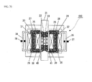
- FIG. 20 An example of a conventional variable spring constant magnetic spring device (referencing, for example, Patent Citation 1) is shown in FIG. 20 .
- This variable spring constant magnetic spring device 400 is structured from a movable element 21 (a movable element yoke 22 and a permanent magnet 23) and a stationary element 24 (coils 25 and 26, gap adjusting stationary yokes 27-30, and stationary cores 31 and 32), a case 33 that supports the movable element 21, and gap adjusting mechanisms 34-37 for changing the spacing of the gap between the movable element 21 and the stationary element 24.
- variable spring constant magnetic spring device 400 when there is no electric current flowing in the coils 25 and 26, then the magnetic fluxes 40 and 41 from the permanent magnet 23 flow through the yokes 27-32 of the stationary element 24, and the movable element 21 is in a stable state at displacement 0. Because of this, an attractive force is produced that tends to return the movable element 21 to the center point (the origin) of displacement 0, regardless of whether the movable element 21 has a positive displacement or whether it has a negative displacement. Given this, a spring force (a magnetic spring force) is produced in relation to the linear movement of the movable element 21 in a linear direction through the attractive force of the permanent magnet 23 alone.
- variable spring constant magnetic spring device 400 it is possible to vary the spring constant through applying electric currents to the coils 25 and 26, there is the need for continuous consumption of electric power in order to have the magnetic fluxes from the coils act on the magnetic flux from the permanent magnet. This increases the power consumption. Moreover, the greater the power consumed, the greater the heat produced as well, which causes variability in the magnetic characteristics, which is problematic in that this causes difficulties in control.
- Patent Document 1 Japanese Unexamined Patent Application Publication 2004-360747
- the present invention was created in order to solve the issues set forth above, and the object thereof is to provide a magnetic spring device wherein an arbitrary change in spring characteristics can be maintained without producing the need to continuously consume electric power.
- the present invention comprises: a permanent magnet; a first yoke and a second yoke, disposed so as to oppose each other with the permanent magnet interposed therebetween; a movable element, made from a magnetizable body, provided so as to enable linear movement in the axial direction thereof, in a state wherein the location of the axis is constrained, between the first yoke and the second yoke, away from the permanent magnet, where the magnetic path of the magnetic flux that exits from the N-pole of the permanent magnet and returns to the S-pole is formed together with the first yoke and the second yoke; and a magnetic flux distribution controlling portion for changing the distribution of the amount of magnetic flux that is provided from the permanent magnet through the first yoke and the second yoke to the movable element, and the amount of magnetic flux from the permanent magnet that is not provided to the movable element.
- the distribution of the amount of magnetic flux that is provided to the movable element from the permanent magnet through the first and second yokes and the amount of magnetic flux that is not provided to the variable element from the permanent magnet can be changed, thus making it possible to maintain an arbitrary change in the spring characteristics without producing the need to consume electric power continuously such as when causing magnetic flux from a coil to act on magnetic flux from a permanent magnet.
- the reason why it is not been possible to change the magnetic flux of a permanent magnet is the difficulty in controlling the magnetic force, when compared to that of an electromagnet.
- the inventor in the present invention noticed that, conversely, reproducible magnetic force control is achieved through stabilizing the magnetic flux of a permanent magnet. Given this, the inventor of the present invention arrived at the idea of enabling control by varying the distribution of the amount of magnetic flux that is provided to the movable element and the amount of magnetic flux that is not provided to the movable element, through branching and providing stabilized magnetic flux.
- the embodiments described below illustrated examples of mechanisms for changing the distributions of the amounts of the stabilized magnetic flux.
- FIG. 1 is a diagram illustrating the critical portions of a magnetic spring device according to a first embodiment according to the present invention.
- 1 is a permanent magnet that produces a magnetic flux that exits from a N-pole and returns to a S-pole;
- 2 and 3 are first and second yokes for forming a magnetic path for the magnetic flux that exits from the N-pole of the permanent magnet 1 and returns to the S-pole thereof,
- 4 is a movable element, made from a magnetizable material, provided so as to enable linear motion, in the axial direction, in a state wherein the position of the axial center O thereof is constrained into a space within the magnetic path formed by the first yoke 2 and the second yoke 3;
- 5 is a shaft (a non-magnetic shaft) made from a non-magnetizable material (a material such as SUS 316, aluminum, bronze, or the like, that is a material wherein the magnetic effect on the magnetic circuit is of a level that can
- the first yoke 2 and the second yoke 3 are disposed facing each other with the permanent magnet 1 interposed therebetween.
- the surfaces on the sides wherein the first yoke 2 and the second yoke 3 face each other are termed the “inner surfaces” 2b and 3b, and the surfaces on the sides opposite from the inner surfaces 2b and 3b are termed the "outer surfaces" 2a and 3a.
- the top surface and the bottom surface correspond, respectively, to the outer surface 2a and the inner surface 2b
- the second yoke 3 the top surface and the bottom surface correspond, respectively, to the inner surface 3b and the outer surface 3a.
- the first yoke 2 and the second yoke 3 have, on one end of each, respective through holes 2-1 and 3-1 of essentially identical diameters, disposed so that the axes of these through holes 2-1 and 3-1 are coincident.
- the movable element 4 is of a columnar shape, and is disposed so that the axial line O thereof is coincident with the axes of the through holes 2-1 and 3-1 of the first yoke 2 and the second yoke 3, and so as to cross both of these through holes 2-1 and 3-1. That is, the state is one wherein at least a portion of the movable element 4 is inserted into the through holes 2-1 and 3-1.
- the length L of the movable element 4 is about the same as the distance H between the outer surface (the top surface) 2a of the first yoke 2 and the outer surface (the bottom surface) 3a of the second yoke 3.
- the non-magnetic shaft 5 that is connected to the top end portion of the movable element 4 connects the movable element 4, for which the length is set to be short, to an external member (not shown), to have the role of transmitting force, and, at the same time, has the role of setting the required distance to the external member (between about 10 and 20 mm), to suppress leakage of magnetic flux to the outside and to magnetically shield the outside.
- the non-magnetic shaft 5 is connected to the top end portion of the movable element 4, it may instead be connected to the bottom end portion of the movable element 4, or may be connected to both end portions thereof.
- the movable element 4 is provided so as to be able to move linearly in the axial direction in a state wherein the position of the axial center O thereof is constrained (in a state wherein movement in the horizontal direction of the movable element 4 is constrained) by a guide, not shown. That is, the movable element 4 penetrates through the through holes 2-1 and 3-1 in a state wherein the outer peripheral surface 4a of the movable element 4 is away from the inner periphery of surfaces 2-1a and 3-1a of the through holes 2-1 and 3-1.
- a non-magnetic bearing may be provided that enables easy sliding of the surfaces between the outer peripheral surface 4a of the movable element 4 and the inner peripheral surfaces 2-1a and 3-1a of the through holes 2-1 and 3-1. If there were no mechanism, such as the guide or the non-magnetic bearing, or the like, to separate the outer peripheral surface 4a of the movable element 4 and the inner peripheral surfaces 2-1a and 3-1a of the through holes 2-1 and 3-1, then the magnetic attractive force would cause the movable element 4 to be magnetized to the yokes 2 and 3, so that the movable element 4 ordinarily would not move unless a force of at least several dozen times the maximum magnetic spring force were produced.
- the permanent magnet 1 is of a circular columnar shape, with one side, in the axial direction, thereof magnetized to the N-pole and the other side magnetized to the S-pole.
- This permanent magnet 1 is disposed in a hollow space between the first yoke 2 and the second yoke 3, away from the movable element 4 at the end portion that is on the side opposite from the side wherein the movable element 4 is provided, with the outer peripheral surface 1a thereof facing the bottom surface 2b of the first yoke 2 and the top surface 3b of the second yoke 3.
- the permanent magnet 1 is made from, for example, a rare earth magnet, such as neodymium or samarium cobalt, or a ferrite magnet, or the like.
- the yokes 2 and 3 and the movable element 4 are made from a soft magnetic material that has a high saturation magnetic flux density and a high magnetic permeability, a low magnetic coercive force, and a little magnetic hysteresis (such as, for example, a magnetic iron plate, magnetic soft iron, permalloy, or the like).
- the motor M1 is connected to the permanent magnet 1, and rotates the permanent magnet 1 around the axis P thereof.
- an ultrasonic motor that has an encoder, for detecting the angle of rotation, is used as the motor M1.
- the ultrasonic motor maintains the position of the angle of rotation at which it stopped, even if the power is turned OFF, and thus only needs to use electric power when rotating the permanent magnet 1.
- This magnetic spring device 100A produces a spring force (a magnetic spring force) that tends to return the movable element 4 to the center position (the origin) of the displacement 0 through the magnetic force (the attractive force) that acts between the movable element 4 and the first yoke 2 and second yoke 3, where the magnetic flux 6 that exits the N-pole and returns to the S-pole of the permanent magnet 1 flows through the magnetic path of the first yoke 2, the movable element 4, and the second yoke 3.
- a spring force a magnetic spring force
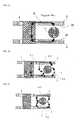
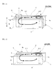
- FIG. 2A through FIG. 2C and FIG. 3 are cross-sectional diagrams wherein the magnetic spring device 100A, illustrated in FIG. 1 , is viewed from the axial direction of the movable element 4 and from the direction perpendicular thereto (a front view).
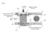
- the magnetic spring force is produced through an operating principle such as shown in FIG. 3 . That is, a magnetic spring force f1 in the vertical direction (the axial direction) is produced that tends to return the movable element 4 to the center, as the axial-direction component vector of the attractive force f, through the attractive force f that is directed at an angle between the end portion on the side of the movable element 4 that has been pressed in and the through hole 2-1 of the yoke 2 (or the through hole 3-1 of the yoke 3) on the side wherein the pressing occurred, when the movable element 4 has been pressed in, by the external force F, between the facing yokes 2 and 3.
- the magnetic spring force f1 will be at a maximum when the N-pole and S-pole of the permanent magnet 1 are in a state such as in FIG. 2A , that is, when the N-pole directly faces the bottom surface 2b of the first yoke 2 and the S-pole directly faces the top surface 3b of the second yoke 3.
- the angular position of the permanent magnet 1 at this time is defined as a magnet angle of 0°.
- the permanent magnet 1 is rotated and, as illustrated in FIG. 2B , the magnet angle of the permanent magnet what is put to 45°.
- the magnetic flux 6 that exits the N-pole of the permanent magnet 1 and returns to the S-pole is split into magnetic flux 6-1 that is directed toward the movable element 4, and magnetic flux 6-2 that creates a closed loop from the N-pole to the S-pole through the yoke and space that are in the vicinity of the permanent magnet 1, without being directed to the movable element 4. That is, the magnetic path of the magnetic flux that flows from the permanent magnet 1 is changed, reducing the amount of magnetic flux to the movable element 4 that is provided from the permanent magnet 1. Doing so reduces the magnetic attraction, weakening the magnetic spring force f1.
- the permanent magnet 1 is rotated as illustrated in FIG. 2C to a magnet angle of 90° for the permanent magnet 1.
- the motor M1 functions as the magnetic flux distribution controlling portion for changing the distribution of the amount of magnetic flux 6-1 and the amount of magnetic flux 6-2.
- the motor M1 may also be provided as a magnetic flux supply quantity controlling portion for changing the proportion of the magnetic flux that is provided to the movable element 4, of the magnetic flux that is produced by the permanent magnet 1.
- the same effect would be produced if the orientation of the magnetic poles of the permanent magnet 1 had the N-pole and S-pole reversed.
- the length L of the movable element 4 being about the same as the distance H between the yokes 2 and 3 causes the magnetic spring force production to be efficient, and is thus preferred, it may instead be longer.
- it may also be shorter, in a range wherein the magnetic flux flows between the yokes 2 and 3 through the movable element 4, the efficiency would be poor because magnetic spring forces would act on both ends of the movable element 4 in opposing directions.
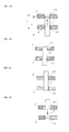
- FIG. 4A through FIG. 4D illustrate states wherein magnetic spring force is produced.
- the movable element 4 is pulled into the through hole 2-1 of the first yoke 2.
- the pulling force does not work.
- the state in FIG. 4D is reached, the movable element 4 is pulled into the through hole 3-1 of the second yoke 3.
- FIG. 4A through FIG. 4D are explanatory diagrams that ignore the force of gravity. Even if gravity is applied, the device will still operate without problems. In this case, a location that has been moved downward by an amount commensurate with the weight of the movable element 4 will become the origin.
- the length L of the movable element 4 is longer than the distance H between the yokes 2 and 3, enabling a region wherein no magnetic spring force is in effect (corresponding to the length of the long portion).
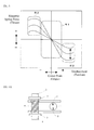
- FIG. 5 shows a schematic diagram for explaining one example of the spring characteristics of the magnetic spring device 100A.
- the horizontal axis is the displacement of the movable element 4
- the vertical axis is the magnetic spring force (thrust) produced by the movable element 4.
- the magnetic spring force that is produced by the movable element 4 is zero at the origin, and becomes larger the further from the origin.
- the magnetic spring force is changed by rotating the permanent magnet 1.
- the region will be a variable magnetic spring constant range (or a variable compliance range) R1 wherein the magnetic spring force varies linearly with displacement, where the spring constant or compliance (the inverse of the spring constant) is changed through rotating the permanent magnet 1.
- the range will be a (constant) variable magnetic spring force range R2, where a magnetic spring force (thrust) that is essentially constant in relation to the displacement is changed through rotating the permanent magnet 1.
- an initial location for the movable element 4 may be set through attaching a mechanical stopper 7 to the shaft 5 and using only the variable magnetic spring constant region R1 ( FIG. 6A ), or instead using only the (constant) variable magnetic spring force region R2 ( FIG. 6B ), and the spring constant or constant magnetic spring force, or both, can be selected depending on the requirements of the work.
- FIG. 7 shows one example of the spring characteristics of the magnetic spring device 100A.
- curve I shows the spring characteristics when the magnet angle of the permanent magnet 1 is at 0°
- curve II shows the spring characteristics when the magnet angle of the permanent magnet 1 is at 45°
- curve III shows the spring characteristics when the magnet angle of the permanent magnet 1 is at 60°
- curve IV shows the spring characteristics when the magnet angle of the permanent magnet 1 is at 75°
- curve V shows the spring characteristics when the magnet angle of the permanent magnet 1 is at 90°.
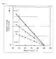
- FIG. 8 shows an example of the relationship between the magnet angle and the magnetic spring force (thrust). It can be appreciated that a magnetic spring force that changes linearly in proportion to the magnet angle is obtained in the range of magnet angles between 45° and 90°.
- the first yoke 2 and the second yoke 3 are simple flat plates.
- the yoke surface in the part that faces the outer peripheral surface 1a of the permanent magnet 1 may be shaped to conform to the curvature of the outer peripheral surface 1a of the permanent magnet 1. Doing so reduces the magnetic resistance between the permanent magnet 1 and the yokes 2 and 3, so that a greater amount of magnetic flux will flow more efficiently.
- the structure may be one wherein the yoke surfaces are twisted 90° partway through, enabling a structure that is well suited to reducing the size through disposal of the axial direction of the permanent magnet 1 in parallel with the movable element 4.
- the yoke surfaces of the parts that face the outer peripheral surface 1a of the permanent magnet 1 may be shaped so as to conform with the curvature of the outer peripheral surface 1a of the permanent magnet 1, so as to enable the magnetic flux to flow efficiently.
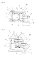
- FIG. 11 is a diagram illustrating the critical components in a magnetic spring device that is a second embodiment according to the present invention.
- this magnetic spring device 200 200A
- a circular columnar movable element 4 is disposed so that the axial direction thereof is essentially perpendicular to the direction in which the yokes 2 and 3 face each other.
- the inner surface of the first yoke 2 and the inner surface of the second yoke 3 are essentially parallel to each other, and the axial center O and the axial direction thereof, of the movable element 4, are essentially parallel with the inner surfaces of the first and second yokes 2 and 3.
- the movable element 4 is provided so as to be able to move linearly in the axial direction, in parallel with the planar directions of the yokes 2 and 3 and the axial direction of the movable element 4, in a state wherein the position of the axial center O thereof is constrained (in a state wherein movement in the horizontal direction of the movable element 4 is constrained) by a guide, not shown. That is, the movable element 4 is disposed between the yokes 2 and 3 in a state wherein the outer peripheral surface 4a of the movable element 4 is away from the inner surfaces of the yokes 2 and 3.
- a shaft (a non-magnetic shaft) 5 made from a non-magnetizable material (a material such as SUS 316, aluminum, bronze, or the like, that is a material wherein the magnetic effect on the magnetic circuit is of a level that can be ignored) is connected to the top end portion of the movable element 4 so as to propagate the force to an external element (not shown). While, in this example, the non-magnetic shaft 5 is connected to the top end portion of the movable element 4, it may instead be connected to the bottom end portion of the movable element 4, or may be connected to both end portions thereof.
- a non-magnetic bearing may be provided that enables easy sliding of the surfaces between the outer peripheral surface 4a of the movable element 4 and the inner surface of the yoke. If there were no mechanism, such as the guide or the non-magnetic bearing, or the like, to separate the outer peripheral surface 4a of the movable element 4 and the inner surfaces of the yokes, then the magnetic attractive force would cause the movable element 4 to be magnetized to the yokes 2 and 3, so that the movable element 4 ordinarily would not move unless a force of at least several dozen times the maximum magnetic spring force were produced.
- the shape of the movable element 4 is not limited to being a circular column, but rather may be a square column or a complex shape.
- the length L of the movable element 4 is set to about the same as the width of the yokes 2 and 3 (the lengths of the yokes 2 and 3 in the same direction as the axial direction of the movable element 4) W of the yokes 2 and 3 is about the same as the length L of the movable element 4, or set to be shorter than that.
- the circular columnar permanent magnet 1 that is magnetized in the radial direction is disposed, with the axial direction of the circular cylinder in parallel to the inner surfaces of the yokes, in the space between the opposite sides of the yokes 2 and 3 from the sides wherein the movable element 4 is disposed.
- the axial direction thereof is essentially perpendicular to the direction in which the yokes 2 and 3 oppose each other, disposed between the yokes 2 and 3.
- the permanent magnet 1 is disposed in a state wherein it can rotate around the axis thereof, with the outer peripheral surface 1a thereof not in contact with the first yoke 2 nor the second yoke 3. Note that there are no constraints on the angle between the axial direction of the circular columnar permanent magnet 1 and the lengthwise directions of the yokes 2 and 3, and these need not necessarily be right angles.
- the yoke surfaces in the parts facing the outer peripheral surface 1a of the permanent magnet 1 may be shaped in conformance with the curvature of the outer peripheral surface 1a of the permanent magnet, reducing the magnetic resistance between the permanent magnet 1 and the yokes 2 and 3, to cause a greater amount of magnetic flux to flow more efficiently.
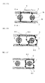
- FIG. 13A through FIG. 13C are diagrams wherein the magnetic spring device 200A, illustrated in FIG. 11 , is viewed from the axial direction of the movable element 4 and from the direction perpendicular thereto (a top view), and FIG. 14 is a cross-sectional diagram along the section A-A in FIG. 13A .
- the magnetic spring force is produced through an operating principle such as shown in FIG. 14 . That is, a magnetic spring force f1 in the vertical direction (the axial direction) is produced that tends to return the movable element 4 to the center, as the axial-direction component vector of the attractive force f, through the attractive force f that is directed at an angle between the end portion on the side of the movable element 4 that has been pressed in and the yoke 2 (or the yoke 3) on the side wherein the pressing occurred, when the movable element 4 has been pressed in, by the external force F, between the facing yokes 2 and 3.
- the attractive force will operate in a slightly diagonal direction, producing a slight magnetic spring force in the vertical direction (the axial direction) with a vector component of the attractive force in the axial direction, to return the movable element 4 to the center, although the effect is large on the side that is pushed.
- the magnetic spring force f1 will be at a maximum when the N-pole and S-pole of the permanent magnet 1 are in a state such as in FIG. 13A , that is, when the N-pole directly faces the bottom surface 2b of the first yoke 2 and the S-pole directly faces the top surface 3b of the second yoke 3.
- the angular position of the permanent magnet 1 at this time is defined as a magnet angle of 0°.
- the permanent magnet 1 is rotated and, as illustrated in FIG. 13B , the magnet angle of the permanent magnet what is put to 45°.
- the magnetic flux 6 that exits the N-pole of the permanent magnet 1 and returns to the S-pole is split into magnetic flux 6-1 that is directed toward the movable element 4, and magnetic flux 6-2 that creates a closed loop from the N-pole to the S-pole through the yoke and space that are in the vicinity of the permanent magnet 1, without being directed to the movable element 4. That is, the magnetic path of the magnetic flux that flows from the permanent magnet 1 is changed, reducing the amount of magnetic flux to the movable element 4 that is provided from the permanent magnet 6. Doing so reduces the magnetic attraction, weakening the magnetic spring force f1.
- the permanent magnet 1 is rotated as illustrated in FIG. 13C to a magnet angle of 90° for the permanent magnet 1.
- the same effect would be produced if the orientation of the magnetic poles of the permanent magnet 1 had the N-pole and S-pole reversed.
- the shape of the movable element 4 may be a rectangular shape, a flat plate shape, or the like, where preferably the area that is facing the yoke surface, in proximity thereto, is large because this reduces the magnetic resistance so that a greater amount of magnetic flux will flow efficiently.
- the length L of the movable element 4 preferably is shorter than about the same as that of the yoke width W, as this produces magnetic spring force efficiently.
- the movable element 4 can be of any shape (for example, the columnar shape may be shortened to a plate shape, or may be lengthened), but the shape and length should be selected depending on the qualities that are desired.
- a circular columnar permanent magnet 1 was used; however, as illustrated in FIG. 15 , a rectangular solid permanent magnet 1', magnetized in opposing directions on either side of a rotational axis P thereof may be used, where this rectangular solid permanent magnet 1' can be rotated into a state that is in proximity to, or away from, the yoke inner surfaces that are faced by the respective magnetic poles.
- a permanent magnet 1' made from a bar magnet may be provided so as to be able to rotate freely between the first yoke 2 and the second yoke 3 with a specific position (for example, the center point) between the N-pole and the S-pole as the axis of rotation P.
- the rectangular solid permanent magnet 1' may be held by a non-magnetic holder 8, and the rectangular solid permanent magnet 1' that is held by the non-magnetic holder 8 may be rotated.
- the permanent magnet 1 may be provided interposed in the center portion between the first yoke 2 and the second yoke 3, essentially in parallel with the yokes 2 and 3, and a bypass yoke 9 that has, for example, a U shape, or the like, may be made from a magnetic material.
- the provision of the bypass yoke 9 causes a stable point, in terms of the rotational force, to appear not just at the angle wherein the respective poles of the permanent magnet 1 are nearest to the inner surfaces of the yokes, but also at angles shifted 90° therefrom. Because of this, it becomes possible to rotate the permanent magnet 1 with less force (torque). Moreover, the scope of the rotational angle for changing the magnetic flux becomes wider, enabling finer control of the magnetic flux.
- the amount of magnetic flux to the movable element 4 was controlled through rotation of the permanent magnet 1. That is, the distribution of the amount of the magnetic flux 6-1 that is provided from the permanent magnet 1 to the movable element 4, and the amount of the magnetic flux 6-2 from the permanent magnet 1 that is not provided to the movable element 4 is changed. As a result, there is no need to always continue consumption of power, such as in a case wherein the effect of magnetic flux from a coil is applied to the magnetic flux of the permanent magnet 1, thus making it possible to change and maintain arbitrary spring characteristics.
- the separate provision of the permanent magnet 1, which supplies magnetic flux, and the movable element 4, which is provided with magnetic flux makes it possible to use a permanent magnet 1 that is able to maintain the magnetic force in order to produce the required spring force, without being affected by constraints in design such as on the size of the movable element 4. That is, in a method wherein the movable element is structured from a movable element yoke and a permanent magnet, when the spring force is to be large, without the effect of the magnetic flux from a coil, then the permanent magnet will be larger, and the movable element will be larger.
- the structures are such that a permanent magnet 1 for supplying magnetic flux and a movable element 4 that is provided with magnetic flux are provided separately, and thus it is possible to secure the magnetic force for obtaining the required spring force by increasing the size of the permanent magnet 1 while maintaining the size of the movable element 4 as-is. Doing so makes it possible to obtain the magnetic force for producing the required spring force, without the effect of the constraints in design such as, for example, the size of the movable element 4, and without using a coil.
- FIG. 18 is a diagram illustrating the critical components in a magnetic spring device that is a third embodiment according to the present invention.
- a rectangular solid permanent magnet 10 is secured rigidly in the center portion of the space between the first yoke 2 and the second yoke 3.
- the top end portion is the N-pole and the bottom end portion is the S-pole, where the N-pole is caused to contact the first yoke 2 and the S-pole is caused to contact the second yoke 3.
- the permanent magnet 10 may have the N-pole and the S-pole in opposite directions, and may be of a shape other than a rectangular solid.
- the movable element 4 is provided so as to be able to move linearly in the axial direction thereof, in a state wherein the position of the axial center O thereof is constrained, between one end portion of the first yoke 2 and one end portion of the second yoke 3.
- a shaft (a non-magnetic shaft) 5 made from a non-magnetizable material (a material such as SUS 316, aluminum, bronze, or the like, that is a material wherein the magnetic effect on the magnetic circuit is of a level that can be ignored) is connected to the top end portion of the movable element 4 so as to propagate the force to an external element (not shown). While, in this example, the non-magnetic shaft 5 is connected to the top end portion of the movable element 4, it may instead be connected to the bottom end portion of the movable element 4, or may be connected to both end portions thereof.
- a gap 11 is provided between the other end portion of the first yoke 2 and the other end portion of the second yoke 3, and this gap 11 is used as a magnetic path through which passes a semicircular magnetizable member 13 that is attached to a shaft 12 of a motor M2. That is, the magnetizable member 13 is disposed away from the permanent magnet 10 within the gap 11 that is provided on the opposite side of the movable element 4, with the permanent magnet 10 interposed therebetween.
- the magnetizable member 13 is made from a soft magnetic body with a thickness that is thinner than the spacing of the gap 11, and is in contact with neither the first yoke 2 nor the second yoke 3.
- the magnetizable member 13 may be of a different shape instead, and is not limited to rotating, but may be structured so as move in a different way, such as with linear motion, and to vary the magnetic resistance within the gap 11 by varying the proportion of the gap 11 that is occupied by the magnetizable body.
- an ultrasonic motor is used for the motor M2.
- the ultrasonic motor maintains the rotational position of the angle of rotation, even if the power is turned OFF, and thus only needs to use electric power when rotating the magnetizable member 13.
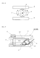
- FIG. 19 shows the overall structure including also a mechanism for guiding the movable element 4.
- the location of the axial center O of the movable element 4 is constrained by guide shafts 14-1 and 14-2.
- the guide shafts 14-1 and 14-2 support a stage 15 that is driven by the non-magnetic shaft 5 that is connected to the movable element 4, while constraining the location of the axial center O of the movable element 4, with up and down motion in a state wherein they are inserted into linear bushes 16-1 and 16-2.
- the magnetic flux 17 that exits the N-pole of the permanent magnet 10 and returns to the S-pole is divided into a magnetic flux 17-1 that is directed toward the movable element 4, and a magnetic flux 17-2 that is directed toward a gap 11 (the magnetic flux that is not provided from the permanent magnet 10 to the movable element 4).
- the magnetic path through which the magnetic flux 17-1 flows shall be termed the main magnetic path
- the magnetic path through which the magnetic flux 17-2 flows shall be termed the bypass magnetic path.
- the bypass magnetic path is formed from the first and second yokes 2 and 3 and the magnetizable member 13.
- this magnetic spring device 300 when the magnetizable member 13 is rotated by the motor M2, the position of the semicircular magnetizable member 13 within the gap 11 of the bypass magnetic path is changed, changing the amount of magnetic flux 17-2 that flows through the bypass magnetic path. That is, the orientation of the magnetizable member 13 that is disposed in the magnetic path of the magnetic flux that is provided from the permanent magnet 10 to the movable element 4 is changed, changing the amount of magnetic flux 17-2 from the permanent magnet 10 that is not provided to the movable element 4. As a result, the amount of magnetic flux 17-1 that flows through the main magnetic path, that is, the amount of magnetic flux that is provided from the permanent magnet 10 to the movable element 4, changes, changing the spring characteristics. Consequently, in this magnetic spring device 300, the motor M2 and the magnetizable member 13 function as the magnetic flux distribution controlling portion for changing the distribution of the amount of magnetic flux 17-1 and the amount of magnetic flux 17-2.
- the amount of magnetic flux to the movable element 4 is controlled through rotating the magnetizable member 13 that is disposed in the gap 11 of the bypass magnetic path. That is, the distribution of the amount of magnetic flux 17-1 that is provided from the permanent magnet 10 to the movable element 4 and the amount of magnetic flux 17-2 from the permanent magnet 10 that is not provided to the movable element 4 is changed. As a result, there is no need to always continue consumption of power, such as in a case wherein the effect of magnetic flux from a coil is applied to the magnetic flux of the permanent magnet 10, thus making it possible to change and maintain arbitrary spring characteristics.
- the separate provision of the permanent magnet 10, which supplies magnetic flux, and the movable element 4, which is provided with magnetic flux makes it possible to use a permanent magnet 10 that is able to maintain the magnetic force in order to produce the required spring force, without being affected by constraints in design such as on the size of the movable element 4. That is, in a method wherein the movable element is structured from a movable element yoke and a permanent magnet, when the spring force is to be large, without the effect of the magnetic flux from a coil, then the permanent magnet will be larger, and the movable element will be larger.
- the structures are such that a permanent magnet 10 for supplying magnetic flux and a movable element 4 that is provided with magnetic flux are provided separately, and thus it is possible to secure the magnetic force for obtaining the required spring force by increasing the size of the permanent magnet 10 while leaving the size of the movable element 4 as it is. Doing so makes it possible to obtain the magnetic force for producing the required spring force, without the effect of the constraints in design such as, for example, the size of the movable element 4, and without using a coil.
- the guide shaft structure illustrated in FIG. 19 makes it possible to prevent rotation of the movable element 4, which is preferred in applications such as in normal assemblies.
- the movable element 4 is able to rotate, either directly or through a bearing that is attached to a coaxial shaft that is connected to the movable element 4, this enables a variable spring force to be produced without contacting the rotational shaft, enabling control of forces in the axial direction in rotating bodies such as drills, drivers, clutches, and the like.
- ultrasonic motors were used for the motor M1 and M2, stepping motors (pulse motors), or the like may be used instead. Because in a stepping motor the operating angle is determined by the number of input pulses, this enables use even without an encoder for detecting the angle of rotation.
- a stepping motor a type that uses a permanent magnet in the stator or rotor may be used, and a type that has a gear may be used. For example, using a gear ratio of 1/100 in a stepping motor that has a gear, makes it fully possible to maintain the position of the angle of rotation at which it stops, even if the power is turned OFF. If not a stepping motor with a gear, even a normal motor can be used if a stopper function is added, such as a latch solenoid that uses a permanent magnet to maintain the state.
- a sensor for detecting the location or displacement of the movable element 4 may be provided, and a magnetic flux distribution controlling portion may control the amount of magnetic flux to the movable element 4 in accordance with the location or displacement of the movable element 4 that is detected by the sensor. This enables more sophisticated control of operations.
- a manual dial that is equipped with a latch function for stopping at specific angular intervals may be provided to use the manual dial to vary the angle of rotation of the permanent magnet 1 and to hold the permanent magnet 1 at the angle of rotation at which it is stopped.
- a manual dial that is equipped with a latch function for stopping at specific angular intervals may be provided to use the manual dial to vary the angle of rotation of the magnetizable member 13 and to hold the magnetizable member 13 at the angle of rotation at which it is stopped.
- a rotational angle maintaining mechanism such as a worm gear may be used instead of the latching mechanism that stops at specific angular intervals, as described above, in which case the angle may be set continuously to any angle.
- the structure of the magnetic spring device 300 that is illustrated in FIG. 18 may use the configuration of the yokes 2 and 3 and of the movable element 4 of the magnetic spring device 200 that is illustrated in FIG. 11 .
- the yokes 2 and 3 may be structured from respective single-layer plates of magnetizable bodies, or may be structured with multiple layers of thin plate of magnetizable bodies.
- layering when the magnetic flux enters or exits in parallel with the direction of the flat surfaces of the individual magnetizable plates, the effects of reverse magnetic fields due to the effects of anisotropy in the shaped magnetism will be small (where the reversed magnetic fields in the direction of thickness of the plates will be large), which is preferable because this enables the magnetic flux to flow efficiently.
- the movable element 4 may also be formed from a single magnetizable body, or may be formed from a stack of magnetizable plates.
Landscapes
- Engineering & Computer Science (AREA)
- General Engineering & Computer Science (AREA)
- Mechanical Engineering (AREA)
- Physics & Mathematics (AREA)
- Electromagnetism (AREA)
- Acoustics & Sound (AREA)
- Aviation & Aerospace Engineering (AREA)
- Power Engineering (AREA)
- Reciprocating, Oscillating Or Vibrating Motors (AREA)
- Vibration Prevention Devices (AREA)
Abstract
Description
- The present invention relates to a magnetic spring device using magnetic attractive force as a spring force.
- Conventionally, a variable spring constant magnetic spring device, wherein the spring constant can be changed freely, has been proposed as a magnetic spring device of this type. This variable spring constant magnetic spring device is used, for example, as a shock absorbing device for preventing damage to components, attached between a work piece (or a hand) and the tip end of a robotic arm that performs assembly of precision components or small components, such as electronic components.
- In assembly by robot, gentle forces are necessary when positioning components because the application of an excessively large contact force would break the component, and after the position has been determined, it is then necessary to press more forcefully. Because of this, a weak force setting, for when performing positioning, and a strong force setting, for after the positioning has been completed, are switched between by the variable spring constant magnetic spring device. Furthermore, it is often necessary to change characteristics of a spring, such as the spring constant or the spring force, such as when a single robotic arm is used for a variety of different jobs, or when changing specifications after installation.
- An example of a conventional variable spring constant magnetic spring device (referencing, for example, Patent Citation 1) is shown in
FIG. 20 . This variable spring constantmagnetic spring device 400 is structured from a movable element 21 (amovable element yoke 22 and a permanent magnet 23) and a stationary element 24 (coils stationary cores 31 and 32), acase 33 that supports themovable element 21, and gap adjusting mechanisms 34-37 for changing the spacing of the gap between themovable element 21 and thestationary element 24. - In this variable spring constant
magnetic spring device 400, when there is no electric current flowing in thecoils magnetic fluxes permanent magnet 23 flow through the yokes 27-32 of thestationary element 24, and themovable element 21 is in a stable state atdisplacement 0. Because of this, an attractive force is produced that tends to return themovable element 21 to the center point (the origin) ofdisplacement 0, regardless of whether themovable element 21 has a positive displacement or whether it has a negative displacement. Given this, a spring force (a magnetic spring force) is produced in relation to the linear movement of themovable element 21 in a linear direction through the attractive force of thepermanent magnet 23 alone. - In contrast, when an electric current is present in the
coils magnetic fluxes magnetic fluxes permanent magnet 23 are weakened by themagnetic fluxes magnetic fluxes permanent magnet 23 through themagnetic fluxes - Moreover, increasing the spacing of the gaps between the
movable element 21 and the stationary element 24 (between 21 and 27, between 21 and 28, between 21 and 29, and between 21 and 30) through the gap adjusting mechanisms 34-37 increases the magnetic resistance, thereby reducing the magnetic attractive force through reducing the magnetic flux that flows through the 27-30 of thestationary element 24 from thepermanent magnet 23, reducing the spring constant. Conversely, decreasing the spacing of the gaps between themovable element 21 and the stationary element 24 (between 21 and 27, between 21 and 28, between 21 and 29, and between 21 and 30) decreases the magnetic resistance, thereby increasing the magnetic attractive force through increasing the magnetic flux that flows through the 27-30 of thestationary element 24 from thepermanent magnet 23, increasing the spring constant. - However, although, with the conventional variable spring constant
magnetic spring device 400 it is possible to vary the spring constant through applying electric currents to thecoils - Patent Document 1: Japanese Unexamined Patent Application Publication
2004-360747 - The present invention was created in order to solve the issues set forth above, and the object thereof is to provide a magnetic spring device wherein an arbitrary change in spring characteristics can be maintained without producing the need to continuously consume electric power.
- In order to achieve such an object, the present invention comprises: a permanent magnet; a first yoke and a second yoke, disposed so as to oppose each other with the permanent magnet interposed therebetween; a movable element, made from a magnetizable body, provided so as to enable linear movement in the axial direction thereof, in a state wherein the location of the axis is constrained, between the first yoke and the second yoke, away from the permanent magnet, where the magnetic path of the magnetic flux that exits from the N-pole of the permanent magnet and returns to the S-pole is formed together with the first yoke and the second yoke; and a magnetic flux distribution controlling portion for changing the distribution of the amount of magnetic flux that is provided from the permanent magnet through the first yoke and the second yoke to the movable element, and the amount of magnetic flux from the permanent magnet that is not provided to the movable element.
- In the present invention, the distribution of the amount of magnetic flux that is provided to the movable element from the permanent magnet through the first and second yokes and the amount of magnetic flux that is not provided to the variable element from the permanent magnet can be changed, thus making it possible to maintain an arbitrary change in the spring characteristics without producing the need to consume electric power continuously such as when causing magnetic flux from a coil to act on magnetic flux from a permanent magnet.
-
-
FIG. 1 is a diagram illustrating the critical portions of a magnetic spring device according to a first embodiment according to the present invention. -
FIG. 2A through FIG. 2C are diagrams illustrating a method for varying the distribution of the amounts of magnetic fluxes in the magnetic spring device illustrated inFIG. 1 . -
FIG. 3 is a diagram for explaining the operating principle in generating a magnetic spring force in the magnetic spring device illustrated inFIG. 1 . -
FIG. 4A through FIG. 4D are diagrams illustrating the states wherein magnetic spring forces are produced in the magnetic spring device illustrated inFIG. 1 . -
FIG. 5 is a conceptual diagram for explaining one example of spring characteristics of the magnetic spring device illustrated inFIG. 1 . -
FIG. 6A through FIG. 6B are diagrams illustrating an example wherein an initial position of the movable element is set through the attachment of a mechanical stopper in the magnetic spring device illustrated inFIG. 1 . -
FIG. 7 is a diagram illustrating one example of spring characteristics of the magnetic spring device illustrated inFIG. 1 . -
FIG. 8 is a diagram illustrating one example of the relationship between the magnet angle and the magnetic spring force (thrust). -
FIG. 9 is a diagram illustrating a modified example of the magnetic spring device illustrated inFIG. 1 . -
FIG. 10 is a diagram illustrating a modified example of the magnetic spring device illustrated inFIG. 1 . -
FIG. 11 is a diagram illustrating the critical portions of a magnetic spring device according to a second embodiment according to the present invention. -
FIG. 12 is a diagram illustrating a modified example of the magnetic spring device illustrated inFIG. 11 . -
FIG. 13A through FIG. 13C are diagrams illustrating a method for varying the distribution of the amounts of magnetic fluxes in the magnetic spring device illustrated inFIG. 11 . -
FIG. 14 is a diagram for explaining the operating principle in generating a magnetic spring force in the magnetic spring device illustrated inFIG. 11 . -
FIG. 15 is a diagram illustrating an example wherein a rectangular solid permanent magnet is used. -
FIG. 16 is a diagram illustrating an example wherein a rectangular solid permanent magnet is held by a non-magnetic holder. -
FIG. 17 is a diagram illustrating an example wherein a bypass yoke, made from a magnetizable material is provided with a permanent magnet interposed therein. -
FIG. 18 is a diagram illustrating the critical portions of a magnetic spring device according to a third embodiment according to the present invention. -
FIG. 19 is a diagram illustrating an overall structure that includes a mechanism for guiding the movable element in the magnetic spring device illustrated inFIG. 18 . -
FIG. 20 is a diagram illustrating one example of a conventional variable spring constant magnetic spring device. - Conventionally, the reason why it is not been possible to change the magnetic flux of a permanent magnet is the difficulty in controlling the magnetic force, when compared to that of an electromagnet. The inventor in the present invention noticed that, conversely, reproducible magnetic force control is achieved through stabilizing the magnetic flux of a permanent magnet. Given this, the inventor of the present invention arrived at the idea of enabling control by varying the distribution of the amount of magnetic flux that is provided to the movable element and the amount of magnetic flux that is not provided to the movable element, through branching and providing stabilized magnetic flux. The embodiments described below illustrated examples of mechanisms for changing the distributions of the amounts of the stabilized magnetic flux.
- A embodiment according to the present disclosure will be explained below in detail, based on the drawings.
-
FIG. 1 is a diagram illustrating the critical portions of a magnetic spring device according to a first embodiment according to the present invention. In thisfigure, 1 is a permanent magnet that produces a magnetic flux that exits from a N-pole and returns to a S-pole; 2 and 3 are first and second yokes for forming a magnetic path for the magnetic flux that exits from the N-pole of thepermanent magnet 1 and returns to the S-pole thereof, 4 is a movable element, made from a magnetizable material, provided so as to enable linear motion, in the axial direction, in a state wherein the position of the axial center O thereof is constrained into a space within the magnetic path formed by thefirst yoke 2 and thesecond yoke 3; 5 is a shaft (a non-magnetic shaft) made from a non-magnetizable material (a material such as SUS 316, aluminum, bronze, or the like, that is a material wherein the magnetic effect on the magnetic circuit is of a level that can be ignored) that is connected to the top end portion of themovable element 4; and M1 is a motor for rotating thepermanent magnet 1. - In this magnetic spring device 100 (100A), the
first yoke 2 and thesecond yoke 3 are disposed facing each other with thepermanent magnet 1 interposed therebetween. The surfaces on the sides wherein thefirst yoke 2 and thesecond yoke 3 face each other are termed the "inner surfaces" 2b and 3b, and the surfaces on the sides opposite from theinner surfaces FIG. 1 , for thefirst yoke 2, the top surface and the bottom surface correspond, respectively, to theouter surface 2a and theinner surface 2b, and for thesecond yoke 3, the top surface and the bottom surface correspond, respectively, to theinner surface 3b and theouter surface 3a. - The
first yoke 2 and thesecond yoke 3 have, on one end of each, respective through holes 2-1 and 3-1 of essentially identical diameters, disposed so that the axes of these through holes 2-1 and 3-1 are coincident. Themovable element 4 is of a columnar shape, and is disposed so that the axial line O thereof is coincident with the axes of the through holes 2-1 and 3-1 of thefirst yoke 2 and thesecond yoke 3, and so as to cross both of these through holes 2-1 and 3-1. That is, the state is one wherein at least a portion of themovable element 4 is inserted into the through holes 2-1 and 3-1. - Moreover, the length L of the
movable element 4 is about the same as the distance H between the outer surface (the top surface) 2a of thefirst yoke 2 and the outer surface (the bottom surface) 3a of thesecond yoke 3. Additionally, thenon-magnetic shaft 5 that is connected to the top end portion of themovable element 4 connects themovable element 4, for which the length is set to be short, to an external member (not shown), to have the role of transmitting force, and, at the same time, has the role of setting the required distance to the external member (between about 10 and 20 mm), to suppress leakage of magnetic flux to the outside and to magnetically shield the outside. While, in this example, thenon-magnetic shaft 5 is connected to the top end portion of themovable element 4, it may instead be connected to the bottom end portion of themovable element 4, or may be connected to both end portions thereof. - Moreover, the
movable element 4 is provided so as to be able to move linearly in the axial direction in a state wherein the position of the axial center O thereof is constrained (in a state wherein movement in the horizontal direction of themovable element 4 is constrained) by a guide, not shown. That is, themovable element 4 penetrates through the through holes 2-1 and 3-1 in a state wherein the outerperipheral surface 4a of themovable element 4 is away from the inner periphery of surfaces 2-1a and 3-1a of the through holes 2-1 and 3-1. - Note that instead of the provision of a guide, a non-magnetic bearing may be provided that enables easy sliding of the surfaces between the outer
peripheral surface 4a of themovable element 4 and the inner peripheral surfaces 2-1a and 3-1a of the through holes 2-1 and 3-1. If there were no mechanism, such as the guide or the non-magnetic bearing, or the like, to separate the outerperipheral surface 4a of themovable element 4 and the inner peripheral surfaces 2-1a and 3-1a of the through holes 2-1 and 3-1, then the magnetic attractive force would cause themovable element 4 to be magnetized to theyokes movable element 4 ordinarily would not move unless a force of at least several dozen times the maximum magnetic spring force were produced. - Moreover, in this
magnetic spring device 100A, thepermanent magnet 1 is of a circular columnar shape, with one side, in the axial direction, thereof magnetized to the N-pole and the other side magnetized to the S-pole. Thispermanent magnet 1 is disposed in a hollow space between thefirst yoke 2 and thesecond yoke 3, away from themovable element 4 at the end portion that is on the side opposite from the side wherein themovable element 4 is provided, with the outerperipheral surface 1a thereof facing thebottom surface 2b of thefirst yoke 2 and thetop surface 3b of thesecond yoke 3. That is, it is disposed in a space between thefirst yoke 2 and thesecond yoke 3 with the axial direction of the circular columnarpermanent magnet 1 parallel to the directions of the surfaces of the opposing faces (the inner surfaces) of theyokes permanent magnet 1 and the lengthwise directions of theyokes - Moreover, in the present embodiment, the
permanent magnet 1 is made from, for example, a rare earth magnet, such as neodymium or samarium cobalt, or a ferrite magnet, or the like. Theyokes movable element 4 are made from a soft magnetic material that has a high saturation magnetic flux density and a high magnetic permeability, a low magnetic coercive force, and a little magnetic hysteresis (such as, for example, a magnetic iron plate, magnetic soft iron, permalloy, or the like). - The motor M1 is connected to the
permanent magnet 1, and rotates thepermanent magnet 1 around the axis P thereof. In the present embodiment, an ultrasonic motor that has an encoder, for detecting the angle of rotation, is used as the motor M1. The ultrasonic motor maintains the position of the angle of rotation at which it stopped, even if the power is turned OFF, and thus only needs to use electric power when rotating thepermanent magnet 1. - This
magnetic spring device 100A produces a spring force (a magnetic spring force) that tends to return themovable element 4 to the center position (the origin) of thedisplacement 0 through the magnetic force (the attractive force) that acts between themovable element 4 and thefirst yoke 2 andsecond yoke 3, where themagnetic flux 6 that exits the N-pole and returns to the S-pole of thepermanent magnet 1 flows through the magnetic path of thefirst yoke 2, themovable element 4, and thesecond yoke 3. - The method for changing the distribution of the amounts of magnetic flux, and the operating principle for producing the magnetic spring force, in the
magnetic spring device 100A illustrated inFIG. 1 will be explained in reference toFIG. 2A through FIG. 2C andFIG.3 . Note thatFIG. 2A through FIG. 2C andFIG. 3 are cross-sectional diagrams wherein themagnetic spring device 100A, illustrated inFIG. 1 , is viewed from the axial direction of themovable element 4 and from the direction perpendicular thereto (a front view). - In the
magnetic spring device 100A, the magnetic spring force is produced through an operating principle such as shown inFIG. 3 . That is, a magnetic spring force f1 in the vertical direction (the axial direction) is produced that tends to return themovable element 4 to the center, as the axial-direction component vector of the attractive force f, through the attractive force f that is directed at an angle between the end portion on the side of themovable element 4 that has been pressed in and the through hole 2-1 of the yoke 2 (or the through hole 3-1 of the yoke 3) on the side wherein the pressing occurred, when themovable element 4 has been pressed in, by the external force F, between the facingyokes - In this
magnetic spring device 100A, the magnetic spring force f1 will be at a maximum when the N-pole and S-pole of thepermanent magnet 1 are in a state such as inFIG. 2A , that is, when the N-pole directly faces thebottom surface 2b of thefirst yoke 2 and the S-pole directly faces thetop surface 3b of thesecond yoke 3. The angular position of thepermanent magnet 1 at this time is defined as a magnet angle of 0°. - From the state, the
permanent magnet 1 is rotated and, as illustrated inFIG. 2B , the magnet angle of the permanent magnet what is put to 45°. In this case, themagnetic flux 6 that exits the N-pole of thepermanent magnet 1 and returns to the S-pole is split into magnetic flux 6-1 that is directed toward themovable element 4, and magnetic flux 6-2 that creates a closed loop from the N-pole to the S-pole through the yoke and space that are in the vicinity of thepermanent magnet 1, without being directed to themovable element 4. That is, the magnetic path of the magnetic flux that flows from thepermanent magnet 1 is changed, reducing the amount of magnetic flux to themovable element 4 that is provided from thepermanent magnet 1. Doing so reduces the magnetic attraction, weakening the magnetic spring force f1. - Moreover, the
permanent magnet 1 is rotated as illustrated inFIG. 2C to a magnet angle of 90° for thepermanent magnet 1. In this case, nearly all of themagnetic flux 6 that exits the N-pole of thepermanent magnet 1 and returns to the S-pole will be the magnetic flux 6-2 that forms the closed loop from the N-pole to the S-pole through the space and yoke in the vicinity of thepermanent magnet 1, minimizing the magnetic spring force f1 (where the magnetic spring force = 0). - In this way, rotating the
permanent magnet 1 by the motor M1 changes the locations of the poles of thepermanent magnet 1 in relation to thefirst yoke 2 and thesecond yoke 3, thereby changing the distribution of the amount of magnetic flux 6-1 that is provided from thepermanent magnet 1 through the first andsecond yokes movable element 4 and the amount of magnetic flux 6-2 from thepermanent magnet 1 that is not provided to themovable element 4, thereby changing the magnetic spring force f1 accordingly. Consequently, in thismagnetic spring device 100A, the motor M1 functions as the magnetic flux distribution controlling portion for changing the distribution of the amount of magnetic flux 6-1 and the amount of magnetic flux 6-2. Note that the motor M1 may also be provided as a magnetic flux supply quantity controlling portion for changing the proportion of the magnetic flux that is provided to themovable element 4, of the magnetic flux that is produced by thepermanent magnet 1. - Note that in this
magnetic spring device 100A, the same effect would be produced if the orientation of the magnetic poles of thepermanent magnet 1 had the N-pole and S-pole reversed. Moreover, although the length L of themovable element 4 being about the same as the distance H between theyokes yokes movable element 4, the efficiency would be poor because magnetic spring forces would act on both ends of themovable element 4 in opposing directions. -
FIG. 4A through FIG. 4D illustrate states wherein magnetic spring force is produced. In the state inFIG. 4A , themovable element 4 is pulled into the through hole 2-1 of thefirst yoke 2. BetweenFIG. 4B and FIG. 4C , the pulling force does not work. When the state inFIG. 4D is reached, themovable element 4 is pulled into the through hole 3-1 of thesecond yoke 3. Note thatFIG. 4A through FIG. 4D are explanatory diagrams that ignore the force of gravity. Even if gravity is applied, the device will still operate without problems. In this case, a location that has been moved downward by an amount commensurate with the weight of themovable element 4 will become the origin. In the example illustrated inFIG. 4 , the length L of themovable element 4 is longer than the distance H between theyokes -
FIG. 5 shows a schematic diagram for explaining one example of the spring characteristics of themagnetic spring device 100A. In this figure, the horizontal axis is the displacement of themovable element 4, and the vertical axis is the magnetic spring force (thrust) produced by themovable element 4. As illustrated in this example, the magnetic spring force that is produced by themovable element 4 is zero at the origin, and becomes larger the further from the origin. Moreover, the magnetic spring force is changed by rotating thepermanent magnet 1. In this case, when themovable element 4 is in the vicinity of the origin, the region will be a variable magnetic spring constant range (or a variable compliance range) R1 wherein the magnetic spring force varies linearly with displacement, where the spring constant or compliance (the inverse of the spring constant) is changed through rotating thepermanent magnet 1. Moreover, when themovable element 4 is at a specific region that is away from the origin, the range will be a (constant) variable magnetic spring force range R2, where a magnetic spring force (thrust) that is essentially constant in relation to the displacement is changed through rotating thepermanent magnet 1. - In the case in this example, as illustrated in
FIG. 6A andFIG. 6B , an initial location for themovable element 4 may be set through attaching amechanical stopper 7 to theshaft 5 and using only the variable magnetic spring constant region R1 (FIG. 6A ), or instead using only the (constant) variable magnetic spring force region R2 (FIG. 6B ), and the spring constant or constant magnetic spring force, or both, can be selected depending on the requirements of the work. -
FIG. 7 shows one example of the spring characteristics of themagnetic spring device 100A. In this figure, curve I shows the spring characteristics when the magnet angle of thepermanent magnet 1 is at 0°, curve II shows the spring characteristics when the magnet angle of thepermanent magnet 1 is at 45°, curve III shows the spring characteristics when the magnet angle of thepermanent magnet 1 is at 60°, curve IV shows the spring characteristics when the magnet angle of thepermanent magnet 1 is at 75°, and curve V shows the spring characteristics when the magnet angle of thepermanent magnet 1 is at 90°. -
FIG. 8 shows an example of the relationship between the magnet angle and the magnetic spring force (thrust). It can be appreciated that a magnetic spring force that changes linearly in proportion to the magnet angle is obtained in the range of magnet angles between 45° and 90°. - Note that in the
magnetic spring device 100A illustrated inFIG. 1 thefirst yoke 2 and thesecond yoke 3 are simple flat plates. However, as with themagnet spring device 100B shown inFIG. 9 , the yoke surface in the part that faces the outerperipheral surface 1a of thepermanent magnet 1 may be shaped to conform to the curvature of the outerperipheral surface 1a of thepermanent magnet 1. Doing so reduces the magnetic resistance between thepermanent magnet 1 and theyokes - Moreover, as in the
magnetic spring device 100C, illustrated inFIG. 10 , the structure may be one wherein the yoke surfaces are twisted 90° partway through, enabling a structure that is well suited to reducing the size through disposal of the axial direction of thepermanent magnet 1 in parallel with themovable element 4. In this case as well, as illustrated inFIG. 10 , the yoke surfaces of the parts that face the outerperipheral surface 1a of thepermanent magnet 1 may be shaped so as to conform with the curvature of the outerperipheral surface 1a of thepermanent magnet 1, so as to enable the magnetic flux to flow efficiently. -
FIG. 11 is a diagram illustrating the critical components in a magnetic spring device that is a second embodiment according to the present invention. In this magnetic spring device 200 (200A), between thefirst yoke 2 and thesecond yoke 3, which are disposed facing each other, essentially in parallel, with a space therebetween, a circular columnarmovable element 4 is disposed so that the axial direction thereof is essentially perpendicular to the direction in which theyokes first yoke 2 and the inner surface of thesecond yoke 3 are essentially parallel to each other, and the axial center O and the axial direction thereof, of themovable element 4, are essentially parallel with the inner surfaces of the first andsecond yokes - Moreover, the
movable element 4 is provided so as to be able to move linearly in the axial direction, in parallel with the planar directions of theyokes movable element 4, in a state wherein the position of the axial center O thereof is constrained (in a state wherein movement in the horizontal direction of themovable element 4 is constrained) by a guide, not shown. That is, themovable element 4 is disposed between theyokes peripheral surface 4a of themovable element 4 is away from the inner surfaces of theyokes - Moreover, a shaft (a non-magnetic shaft) 5 made from a non-magnetizable material (a material such as SUS 316, aluminum, bronze, or the like, that is a material wherein the magnetic effect on the magnetic circuit is of a level that can be ignored) is connected to the top end portion of the
movable element 4 so as to propagate the force to an external element (not shown). While, in this example, thenon-magnetic shaft 5 is connected to the top end portion of themovable element 4, it may instead be connected to the bottom end portion of themovable element 4, or may be connected to both end portions thereof. - Note that instead of the provision of a guide, a non-magnetic bearing may be provided that enables easy sliding of the surfaces between the outer
peripheral surface 4a of themovable element 4 and the inner surface of the yoke. If there were no mechanism, such as the guide or the non-magnetic bearing, or the like, to separate the outerperipheral surface 4a of themovable element 4 and the inner surfaces of the yokes, then the magnetic attractive force would cause themovable element 4 to be magnetized to theyokes movable element 4 ordinarily would not move unless a force of at least several dozen times the maximum magnetic spring force were produced. The shape of themovable element 4 is not limited to being a circular column, but rather may be a square column or a complex shape. - Moreover, in the
magnetic spring device 200A, the length L of themovable element 4 is set to about the same as the width of theyokes 2 and 3 (the lengths of theyokes yokes movable element 4, or set to be shorter than that. Moreover, in thismagnetic spring device 200A, the circular columnarpermanent magnet 1 that is magnetized in the radial direction is disposed, with the axial direction of the circular cylinder in parallel to the inner surfaces of the yokes, in the space between the opposite sides of theyokes movable element 4 is disposed. That is, the axial direction thereof is essentially perpendicular to the direction in which theyokes yokes permanent magnet 1 is disposed in a state wherein it can rotate around the axis thereof, with the outerperipheral surface 1a thereof not in contact with thefirst yoke 2 nor thesecond yoke 3. Note that there are no constraints on the angle between the axial direction of the circular columnarpermanent magnet 1 and the lengthwise directions of theyokes - Moreover, as with the
magnetic spring device 200B illustrated inFIG. 12 , the yoke surfaces in the parts facing the outerperipheral surface 1a of thepermanent magnet 1 may be shaped in conformance with the curvature of the outerperipheral surface 1a of the permanent magnet, reducing the magnetic resistance between thepermanent magnet 1 and theyokes - The method for changing the distribution of the amounts of magnetic flux, and the operating principle for producing the magnetic spring force, in the
magnetic spring device 200A illustrated inFIG. 11 will be explained in reference toFIG. 13A through FIG. 13C andFIG. 14 . Note thatFIG. 13A through FIG. 13C are diagrams wherein themagnetic spring device 200A, illustrated inFIG. 11 , is viewed from the axial direction of themovable element 4 and from the direction perpendicular thereto (a top view), andFIG. 14 is a cross-sectional diagram along the section A-A inFIG. 13A . - In the
magnetic spring device 200A, the magnetic spring force is produced through an operating principle such as shown inFIG. 14 . That is, a magnetic spring force f1 in the vertical direction (the axial direction) is produced that tends to return themovable element 4 to the center, as the axial-direction component vector of the attractive force f, through the attractive force f that is directed at an angle between the end portion on the side of themovable element 4 that has been pressed in and the yoke 2 (or the yoke 3) on the side wherein the pressing occurred, when themovable element 4 has been pressed in, by the external force F, between the facingyokes movable element 4 has been pushed and the end portion of the yoke 3 (or yoke 2) on the side to which it has been pushed, the attractive force will operate in a slightly diagonal direction, producing a slight magnetic spring force in the vertical direction (the axial direction) with a vector component of the attractive force in the axial direction, to return themovable element 4 to the center, although the effect is large on the side that is pushed. - In this
magnetic spring device 200A, the magnetic spring force f1 will be at a maximum when the N-pole and S-pole of thepermanent magnet 1 are in a state such as inFIG. 13A , that is, when the N-pole directly faces thebottom surface 2b of thefirst yoke 2 and the S-pole directly faces thetop surface 3b of thesecond yoke 3. The angular position of thepermanent magnet 1 at this time is defined as a magnet angle of 0°. - From the state, the
permanent magnet 1 is rotated and, as illustrated inFIG. 13B , the magnet angle of the permanent magnet what is put to 45°. In this case, themagnetic flux 6 that exits the N-pole of thepermanent magnet 1 and returns to the S-pole is split into magnetic flux 6-1 that is directed toward themovable element 4, and magnetic flux 6-2 that creates a closed loop from the N-pole to the S-pole through the yoke and space that are in the vicinity of thepermanent magnet 1, without being directed to themovable element 4. That is, the magnetic path of the magnetic flux that flows from thepermanent magnet 1 is changed, reducing the amount of magnetic flux to themovable element 4 that is provided from thepermanent magnet 6. Doing so reduces the magnetic attraction, weakening the magnetic spring force f1. - Moreover, the
permanent magnet 1 is rotated as illustrated inFIG. 13C to a magnet angle of 90° for thepermanent magnet 1. In this case, nearly all of themagnetic flux 6 that exits the N-pole of thepermanent magnet 1 and returns to the S-pole will be the magnetic flux 6-2 that forms the closed loop from the N-pole to the S-pole through the space and yoke in the vicinity of thepermanent magnet 1, minimizing the magnetic spring force f1 (where the magnetic spring force f1 = 0). - Note that in this
magnetic spring device 200A, the same effect would be produced if the orientation of the magnetic poles of thepermanent magnet 1 had the N-pole and S-pole reversed. Moreover, the shape of themovable element 4 may be a rectangular shape, a flat plate shape, or the like, where preferably the area that is facing the yoke surface, in proximity thereto, is large because this reduces the magnetic resistance so that a greater amount of magnetic flux will flow efficiently. Moreover, the length L of themovable element 4 preferably is shorter than about the same as that of the yoke width W, as this produces magnetic spring force efficiently. Furthermore, insofar as it is in a range wherein the magnetic flux flows between theyokes movable element 4, themovable element 4 can be of any shape (for example, the columnar shape may be shortened to a plate shape, or may be lengthened), but the shape and length should be selected depending on the qualities that are desired. - In the first embodiment and second embodiment, set forth above, a circular columnar
permanent magnet 1 was used; however, as illustrated inFIG. 15 , a rectangular solid permanent magnet 1', magnetized in opposing directions on either side of a rotational axis P thereof may be used, where this rectangular solid permanent magnet 1' can be rotated into a state that is in proximity to, or away from, the yoke inner surfaces that are faced by the respective magnetic poles. For example, a permanent magnet 1' made from a bar magnet may be provided so as to be able to rotate freely between thefirst yoke 2 and thesecond yoke 3 with a specific position (for example, the center point) between the N-pole and the S-pole as the axis of rotation P. - Moreover, as illustrated in
FIG. 16 , the rectangular solid permanent magnet 1' may be held by anon-magnetic holder 8, and the rectangular solid permanent magnet 1' that is held by thenon-magnetic holder 8 may be rotated. - Moreover, as with the
magnetic spring device 100D ofFIG. 17 , thepermanent magnet 1 may be provided interposed in the center portion between thefirst yoke 2 and thesecond yoke 3, essentially in parallel with theyokes bypass yoke 9 that has, for example, a U shape, or the like, may be made from a magnetic material. The provision of thebypass yoke 9 causes a stable point, in terms of the rotational force, to appear not just at the angle wherein the respective poles of thepermanent magnet 1 are nearest to the inner surfaces of the yokes, but also at angles shifted 90° therefrom. Because of this, it becomes possible to rotate thepermanent magnet 1 with less force (torque). Moreover, the scope of the rotational angle for changing the magnetic flux becomes wider, enabling finer control of the magnetic flux. - As described above, in the
magnetic spring device 100 according to the first embodiment and in themagnetic spring device 200 according to the second embodiment, the amount of magnetic flux to themovable element 4 was controlled through rotation of thepermanent magnet 1. That is, the distribution of the amount of the magnetic flux 6-1 that is provided from thepermanent magnet 1 to themovable element 4, and the amount of the magnetic flux 6-2 from thepermanent magnet 1 that is not provided to themovable element 4 is changed. As a result, there is no need to always continue consumption of power, such as in a case wherein the effect of magnetic flux from a coil is applied to the magnetic flux of thepermanent magnet 1, thus making it possible to change and maintain arbitrary spring characteristics. - Moreover, the separate provision of the
permanent magnet 1, which supplies magnetic flux, and themovable element 4, which is provided with magnetic flux, makes it possible to use apermanent magnet 1 that is able to maintain the magnetic force in order to produce the required spring force, without being affected by constraints in design such as on the size of themovable element 4. That is, in a method wherein the movable element is structured from a movable element yoke and a permanent magnet, when the spring force is to be large, without the effect of the magnetic flux from a coil, then the permanent magnet will be larger, and the movable element will be larger. In contrast, in the first embodiment and the second embodiment, the structures are such that apermanent magnet 1 for supplying magnetic flux and amovable element 4 that is provided with magnetic flux are provided separately, and thus it is possible to secure the magnetic force for obtaining the required spring force by increasing the size of thepermanent magnet 1 while maintaining the size of themovable element 4 as-is. Doing so makes it possible to obtain the magnetic force for producing the required spring force, without the effect of the constraints in design such as, for example, the size of themovable element 4, and without using a coil. -
FIG. 18 is a diagram illustrating the critical components in a magnetic spring device that is a third embodiment according to the present invention. In thismagnetic spring device 300, a rectangular solidpermanent magnet 10 is secured rigidly in the center portion of the space between thefirst yoke 2 and thesecond yoke 3. With this rectangular solidpermanent magnet 10, the top end portion is the N-pole and the bottom end portion is the S-pole, where the N-pole is caused to contact thefirst yoke 2 and the S-pole is caused to contact thesecond yoke 3. Note that thepermanent magnet 10 may have the N-pole and the S-pole in opposite directions, and may be of a shape other than a rectangular solid. - Moreover, in the same manner as with the first embodiment, the
movable element 4 is provided so as to be able to move linearly in the axial direction thereof, in a state wherein the position of the axial center O thereof is constrained, between one end portion of thefirst yoke 2 and one end portion of thesecond yoke 3. Moreover, a shaft (a non-magnetic shaft) 5 made from a non-magnetizable material (a material such as SUS 316, aluminum, bronze, or the like, that is a material wherein the magnetic effect on the magnetic circuit is of a level that can be ignored) is connected to the top end portion of themovable element 4 so as to propagate the force to an external element (not shown). While, in this example, thenon-magnetic shaft 5 is connected to the top end portion of themovable element 4, it may instead be connected to the bottom end portion of themovable element 4, or may be connected to both end portions thereof. - Moreover, a
gap 11 is provided between the other end portion of thefirst yoke 2 and the other end portion of thesecond yoke 3, and thisgap 11 is used as a magnetic path through which passes a semicircularmagnetizable member 13 that is attached to ashaft 12 of a motor M2. That is, themagnetizable member 13 is disposed away from thepermanent magnet 10 within thegap 11 that is provided on the opposite side of themovable element 4, with thepermanent magnet 10 interposed therebetween. Themagnetizable member 13 is made from a soft magnetic body with a thickness that is thinner than the spacing of thegap 11, and is in contact with neither thefirst yoke 2 nor thesecond yoke 3. Note that themagnetizable member 13 may be of a different shape instead, and is not limited to rotating, but may be structured so as move in a different way, such as with linear motion, and to vary the magnetic resistance within thegap 11 by varying the proportion of thegap 11 that is occupied by the magnetizable body. - As with the first embodiment, an ultrasonic motor is used for the motor M2. The ultrasonic motor maintains the rotational position of the angle of rotation, even if the power is turned OFF, and thus only needs to use electric power when rotating the
magnetizable member 13. -
FIG. 19 shows the overall structure including also a mechanism for guiding themovable element 4. In this example, the location of the axial center O of themovable element 4 is constrained by guide shafts 14-1 and 14-2. The guide shafts 14-1 and 14-2 support astage 15 that is driven by thenon-magnetic shaft 5 that is connected to themovable element 4, while constraining the location of the axial center O of themovable element 4, with up and down motion in a state wherein they are inserted into linear bushes 16-1 and 16-2. - In the
magnetic spring device 300, themagnetic flux 17 that exits the N-pole of thepermanent magnet 10 and returns to the S-pole is divided into a magnetic flux 17-1 that is directed toward themovable element 4, and a magnetic flux 17-2 that is directed toward a gap 11 (the magnetic flux that is not provided from thepermanent magnet 10 to the movable element 4). In the magnetic paths through which themagnetic flux 17 flows, the magnetic path through which the magnetic flux 17-1 flows shall be termed the main magnetic path, and the magnetic path through which the magnetic flux 17-2 flows shall be termed the bypass magnetic path. The bypass magnetic path is formed from the first andsecond yokes magnetizable member 13. - In this
magnetic spring device 300, when themagnetizable member 13 is rotated by the motor M2, the position of the semicircularmagnetizable member 13 within thegap 11 of the bypass magnetic path is changed, changing the amount of magnetic flux 17-2 that flows through the bypass magnetic path. That is, the orientation of themagnetizable member 13 that is disposed in the magnetic path of the magnetic flux that is provided from thepermanent magnet 10 to themovable element 4 is changed, changing the amount of magnetic flux 17-2 from thepermanent magnet 10 that is not provided to themovable element 4. As a result, the amount of magnetic flux 17-1 that flows through the main magnetic path, that is, the amount of magnetic flux that is provided from thepermanent magnet 10 to themovable element 4, changes, changing the spring characteristics. Consequently, in thismagnetic spring device 300, the motor M2 and themagnetizable member 13 function as the magnetic flux distribution controlling portion for changing the distribution of the amount of magnetic flux 17-1 and the amount of magnetic flux 17-2. - As described above, in the
magnetic spring device 300 as set forth in the third embodiment, the amount of magnetic flux to themovable element 4 is controlled through rotating themagnetizable member 13 that is disposed in thegap 11 of the bypass magnetic path. That is, the distribution of the amount of magnetic flux 17-1 that is provided from thepermanent magnet 10 to themovable element 4 and the amount of magnetic flux 17-2 from thepermanent magnet 10 that is not provided to themovable element 4 is changed. As a result, there is no need to always continue consumption of power, such as in a case wherein the effect of magnetic flux from a coil is applied to the magnetic flux of thepermanent magnet 10, thus making it possible to change and maintain arbitrary spring characteristics. - Moreover, the separate provision of the
permanent magnet 10, which supplies magnetic flux, and themovable element 4, which is provided with magnetic flux, makes it possible to use apermanent magnet 10 that is able to maintain the magnetic force in order to produce the required spring force, without being affected by constraints in design such as on the size of themovable element 4. That is, in a method wherein the movable element is structured from a movable element yoke and a permanent magnet, when the spring force is to be large, without the effect of the magnetic flux from a coil, then the permanent magnet will be larger, and the movable element will be larger. In contrast, in the third embodiment, the structures are such that apermanent magnet 10 for supplying magnetic flux and amovable element 4 that is provided with magnetic flux are provided separately, and thus it is possible to secure the magnetic force for obtaining the required spring force by increasing the size of thepermanent magnet 10 while leaving the size of themovable element 4 as it is. Doing so makes it possible to obtain the magnetic force for producing the required spring force, without the effect of the constraints in design such as, for example, the size of themovable element 4, and without using a coil. - The guide shaft structure illustrated in
FIG. 19 makes it possible to prevent rotation of themovable element 4, which is preferred in applications such as in normal assemblies. On the other hand, when themovable element 4 is able to rotate, either directly or through a bearing that is attached to a coaxial shaft that is connected to themovable element 4, this enables a variable spring force to be produced without contacting the rotational shaft, enabling control of forces in the axial direction in rotating bodies such as drills, drivers, clutches, and the like. - Note that while in the
magnetic spring devices - Moreover, in the
magnetic spring devices movable element 4 may be provided, and a magnetic flux distribution controlling portion may control the amount of magnetic flux to themovable element 4 in accordance with the location or displacement of themovable element 4 that is detected by the sensor. This enables more sophisticated control of operations. - Moreover, in the
magnetic spring device permanent magnet 1 and to hold thepermanent magnet 1 at the angle of rotation at which it is stopped. In themagnetic spring device 300 as well, as set forth above, rather than using the motor M2, a manual dial that is equipped with a latch function for stopping at specific angular intervals may be provided to use the manual dial to vary the angle of rotation of themagnetizable member 13 and to hold themagnetizable member 13 at the angle of rotation at which it is stopped. Note that a rotational angle maintaining mechanism such as a worm gear may be used instead of the latching mechanism that stops at specific angular intervals, as described above, in which case the angle may be set continuously to any angle. - Moreover, the structure of the
magnetic spring device 300 that is illustrated inFIG. 18 may use the configuration of theyokes movable element 4 of themagnetic spring device 200 that is illustrated inFIG. 11 . - Moreover, in any of the embodiments described above, the
yokes - Moreover, the
movable element 4 may also be formed from a single magnetizable body, or may be formed from a stack of magnetizable plates. - While the present disclosure has been explained above in reference to a embodiment, the present disclosure is not limited to the embodiment set forth above. The structures and details in the present disclosure may be varied in a variety of ways, as can be understood by one skilled in the art, within the scope of technology in the present disclosure. Moreover, the present disclosure may be embodied through combining the various embodiments, insofar as there are no contradictions.
-
- 1, 1': Permanent Magnets
- 2: First Yoke
- 3: Second Yoke
- 4: Movable Element
- 5: Shaft (Non-Magnetic Shaft)
- M1: Motor
- 6, 6-1, 6-2: Magnetic Fluxes
- 8: Holder
- 9: Bypass Yoke
- 10: Permanent Magnet
- 11: Gap
- M2: Motor
- 13: Magnetizable Member
- 14-1, 14-2: Guide Shafts
- 15: Stage
- 16-1, 16-2: Linear Bushes
- 17, 17-1, 17-2: Magnetic Fluxes
- 100 ((100A through 100D), 200 (200A and 200B), 300: Magnetic Spring Devices
Claims (13)
- A magnetic spring device comprising:a permanent magnet;a first yoke and a second yoke, disposed so as to oppose each other with the permanent magnet interposed therebetween;a movable element, made from a magnetizable body, provided so as to enable linear movement in the axial direction thereof, in a state wherein the location of the axis is constrained, between the first yoke and the second yoke, away from the permanent magnet, where the magnetic path of the magnetic flux that exits from the N-pole of the permanent magnet and returns to the S-pole is formed together with the first yoke and the second yoke; anda magnetic flux distribution controlling portion for changing the distribution of the amount of magnetic flux that is provided from the permanent magnet through the first yoke and the second yoke to the movable element, and the amount of magnetic flux from the permanent magnet that is not provided to the movable element.
- A magnetic spring device as set forth in Claim 1, wherein:the magnetic flux distribution controlling portion is configured so as to change the location of a magnetic pole of the permanent magnet in relation to the first yoke and the second yoke.
- A magnetic spring device as set forth in Claim 2, wherein:the magnetic flux distribution controlling portion includes an ultrasonic motor or a stepping motor, connected to the permanent magnet, for changing the location of a magnetic pole of the permanent magnet.
- A magnetic spring device as set forth in Claim 2, further comprising:a bypass yoke, made from a magnetizable body, disposed so that the permanent magnet is interposed between the first yoke and the second yoke.
- A magnetic spring device as set forth in Claim 2, wherein:the permanent magnet is a bar magnet, and is provided so as to be able to rotate on a rotational axis at a specific location between the N-pole and the S-pole.
- A magnetic spring device as set forth in Claim 2, wherein:the magnetic flux distribution controlling portion is a manual dial provided with a latch function that stops and holds the position of an adjusting mechanism for changing the location of a magnetic pole of the permanent magnet at specific locations.
- A magnetic spring device as set forth in Claim 1, wherein:the magnetic flux distribution controlling portion includes a magnetizable member, disposed away from the permanent magnet between the first yoke and the second yoke on the side opposite from the movable element, with the permanent magnet therebetween, so as to form, together with the first yoke and the second yoke, a magnetic path for the magnetic flux that is not provided to the movable element from the permanent magnet.
- A magnetic spring device as set forth in Claim 7, wherein:the magnetic flux distribution controlling portion includes an ultrasonic motor or a stepping motor, connected to the magnetizable member, for moving the magnetizable member.
- A magnetic spring device as set forth in Claim 7, wherein:the magnetic flux distribution controlling portion is a manual dial provided with a latch function that stops and holds the position of an adjusting mechanism for changing an amount of a magnetizing member at specific locations.
- A magnetic spring device as set forth in Claim 1, wherein:the first yoke and the second yoke each includes a through hole of an identical diameter on one end, and are disposed so that the axes of these through holes are aligned; andthe movable element is provided such that the axis of the movable element is coincident with the axes of the through holes of the first and second yokes, so as to be inserted into both through holes.
- A magnetic spring device as set forth in Claim 10, wherein:the first yoke and second yoke include inner surfaces on the sides that face the permanent magnet and outer surfaces on the sides that are opposite of the inner surfaces; andthe length of the movable element is equal to the distance from the outer surface of the first yoke to the outer surface of the second yoke.
- A magnetic spring device as set forth in Claim 1, wherein:the first yoke and second yoke include inner surfaces on the sides that face the permanent magnet;the inner surface of the first yoke is parallel to the inner surface of the second yoke; andthe axis and the axial direction of the movable element are parallel to the inner surface of the first yoke.
- A magnetic spring device as set forth in Claim 1, wherein:a sensor for detecting the location or displacement of the movable element; whereinthe magnetic flux distribution controlling portion controls the distribution of the magnetic flux in accordance with the location or displacement of the movable element, detected by the sensor.
Applications Claiming Priority (2)
| Application Number | Priority Date | Filing Date | Title |
|---|---|---|---|
| JP2012039628A JP5785886B2 (en) | 2012-02-27 | 2012-02-27 | Magnetic spring device |
| PCT/JP2013/053839 WO2013129156A1 (en) | 2012-02-27 | 2013-02-18 | Magnetic spring device |
Publications (2)
| Publication Number | Publication Date |
|---|---|
| EP2821667A1 true EP2821667A1 (en) | 2015-01-07 |
| EP2821667A4 EP2821667A4 (en) | 2016-03-30 |
Family
ID=49082357
Family Applications (1)
| Application Number | Title | Priority Date | Filing Date |
|---|---|---|---|
| EP13755151.1A Withdrawn EP2821667A4 (en) | 2012-02-27 | 2013-02-18 | MAGNETIC SPRING DEVICE |
Country Status (5)
| Country | Link |
|---|---|
| US (1) | US9396858B2 (en) |
| EP (1) | EP2821667A4 (en) |
| JP (1) | JP5785886B2 (en) |
| CN (1) | CN104136800B (en) |
| WO (1) | WO2013129156A1 (en) |
Families Citing this family (9)
| Publication number | Priority date | Publication date | Assignee | Title |
|---|---|---|---|---|
| DE3810701A1 (en) * | 1988-03-29 | 1989-10-12 | Trw Repa Gmbh | REVERSE DEVICE |
| US9324487B1 (en) * | 2014-06-11 | 2016-04-26 | Amazon Technologies, Inc. | Damper for magnetic coupler |
| KR101718039B1 (en) * | 2015-05-11 | 2017-03-20 | 엘지전자 주식회사 | Reciprocating compressor |
| US10208824B2 (en) * | 2015-06-03 | 2019-02-19 | Zachary Stein | Suspension assembly |
| JP6567331B2 (en) * | 2015-06-10 | 2019-08-28 | ナブテスコ株式会社 | Non-contact generator |
| WO2018100715A1 (en) * | 2016-12-01 | 2018-06-07 | 東京製綱株式会社 | Damage evaluation method and damage evaluation device for magnetic linear object |
| JP6660486B2 (en) * | 2016-12-01 | 2020-03-11 | 東京製綱株式会社 | Damage evaluation method and damage evaluation device for magnetic linear body |
| US11852212B2 (en) * | 2019-04-22 | 2023-12-26 | Invetech, Inc. | Adjustable magnetic counterbalance |
| USD992996S1 (en) * | 2020-10-06 | 2023-07-25 | Harry Wong | Magnetic panel holder |
Family Cites Families (26)
| Publication number | Priority date | Publication date | Assignee | Title |
|---|---|---|---|---|
| US2915681A (en) * | 1957-11-20 | 1959-12-01 | Indiana Steel Products Co | Magnet assemblies |
| US3034025A (en) * | 1959-06-10 | 1962-05-08 | Monarch Tool & Machinery Co | Permanent magnet assemblies and quick release mechanisms therefor |
| US3184654A (en) * | 1962-06-14 | 1965-05-18 | Ahmet K Bey | Magnetic holding device |
| US4759116A (en) * | 1983-11-03 | 1988-07-26 | General Electric Company | Method of applying containment shroud on permanent magnet rotors |
| FR2611975B1 (en) * | 1987-03-03 | 1995-02-17 | Commissariat Energie Atomique | PERMANENT MAGNET SYSTEM FOR AN INTENSE MAGNETIC FIELD |
| JPS63306183A (en) * | 1987-06-03 | 1988-12-14 | 株式会社日立製作所 | Anti-vibration device |
| DE3734287A1 (en) * | 1987-10-09 | 1989-04-27 | Manfred Dipl Ing Kessler | VEHICLE DRIVING OR -DRIVE |
| JPH0658278B2 (en) | 1988-02-15 | 1994-08-03 | 株式会社日立製作所 | Magnetic spring support type balance measuring device |
| US5563463A (en) * | 1988-06-08 | 1996-10-08 | General Electric Company | Permanent magnet rotor |
| CN2183468Y (en) * | 1994-02-05 | 1994-11-23 | 崔汉平 | Permanent suspension damper |
| US5877664A (en) * | 1996-05-08 | 1999-03-02 | Jackson, Jr.; John T. | Magnetic proximity switch system |
| KR100281474B1 (en) | 1997-05-16 | 2001-02-01 | 후지타 히토시 | Energy extracting mechanism having a magnetic spring |
| US6246561B1 (en) * | 1998-07-31 | 2001-06-12 | Magnetic Revolutions Limited, L.L.C | Methods for controlling the path of magnetic flux from a permanent magnet and devices incorporating the same |
| JP2002021923A (en) | 2000-07-11 | 2002-01-23 | Delta Tooling Co Ltd | Magnetic damping mechanism |
| FI120863B (en) * | 2002-10-18 | 2010-04-15 | Biocontrol Systems Inc | Magnetic transfer method and microparticle transfer device |
| CN1431409A (en) * | 2003-01-27 | 2003-07-23 | 浙江大学 | Active and precise isolation mounting device |
| JP2004360747A (en) | 2003-06-03 | 2004-12-24 | Canon Inc | Spring constant variable magnetic spring device |
| JP4296105B2 (en) | 2004-02-20 | 2009-07-15 | 株式会社デルタツーリング | Magnet unit |
| JP2006108615A (en) * | 2004-09-07 | 2006-04-20 | Toshiba Corp | Electromagnetic actuator |
| US7161451B2 (en) * | 2005-04-14 | 2007-01-09 | Gm Global Technology Operations, Inc. | Modular permanent magnet chuck |
| KR100708013B1 (en) * | 2006-04-24 | 2007-04-16 | 이용구 | Magnetic chuck |
| WO2008105041A1 (en) * | 2007-02-23 | 2008-09-04 | Pascal Engineering Corporation | Magnetic fixing device |
| WO2010106409A1 (en) * | 2009-03-19 | 2010-09-23 | Robert Bosch Gmbh | Magnetic locking system |
| US8183965B2 (en) * | 2010-04-09 | 2012-05-22 | Creative Engineering Solutions, Inc. | Switchable core element-based permanent magnet apparatus |
| GB2485149B (en) * | 2010-11-02 | 2014-11-05 | Dyson Technology Ltd | Method of manufacturing a magnet assembly |
| KR101319052B1 (en) * | 2013-06-07 | 2013-10-17 | 최태광 | Magnetic substance holding device using permanent magnet energy control |
-
2012
- 2012-02-27 JP JP2012039628A patent/JP5785886B2/en not_active Expired - Fee Related
-
2013
- 2013-02-18 EP EP13755151.1A patent/EP2821667A4/en not_active Withdrawn
- 2013-02-18 CN CN201380010969.0A patent/CN104136800B/en not_active Expired - Fee Related
- 2013-02-18 WO PCT/JP2013/053839 patent/WO2013129156A1/en not_active Ceased
- 2013-02-18 US US14/380,855 patent/US9396858B2/en not_active Expired - Fee Related
Also Published As
| Publication number | Publication date |
|---|---|
| JP2013174318A (en) | 2013-09-05 |
| US9396858B2 (en) | 2016-07-19 |
| JP5785886B2 (en) | 2015-09-30 |
| EP2821667A4 (en) | 2016-03-30 |
| CN104136800A (en) | 2014-11-05 |
| US20150028975A1 (en) | 2015-01-29 |
| WO2013129156A1 (en) | 2013-09-06 |
| CN104136800B (en) | 2015-11-25 |
Similar Documents
| Publication | Publication Date | Title |
|---|---|---|
| US9396858B2 (en) | Magnetic spring device | |
| TW526629B (en) | Magnet movable electromagnetic actuator | |
| US4533890A (en) | Permanent magnet bistable solenoid actuator | |
| WO2014194140A3 (en) | Electromagnetic opposing field actuators | |
| US10389197B2 (en) | Linear electromagnetic actuator comprising two independent moving members | |
| JP2008259413A (en) | Linear actuator | |
| WO2014168236A1 (en) | Bistable moving device | |
| JP2014081002A (en) | Magnetic spring device | |
| CN103683790A (en) | Permanent magnet straight reciprocating motion device | |
| JP2015053816A (en) | Bistable moving device | |
| EP2860739A1 (en) | Solenoid | |
| CN101994761A (en) | Double-permanent magnet outer-rotor permanent magnet biased radial magnetic bearing | |
| KR20170100928A (en) | Solenoid actuator | |
| US10186914B2 (en) | Input amplitude modulation control for a multi-degree of freedom electromagnetic machine | |
| WO2014168109A1 (en) | Magnetic spring device | |
| CN110111972B (en) | Bidirectional self-sustaining electromagnet with stable position based on spring pressure and magnetic resistance | |
| CN117116597B (en) | Electromagnetic actuators, solenoid valves and tactile display modules | |
| US8304952B2 (en) | Electric motor with no counter electromotive force | |
| JP2014095429A (en) | Magnetic spring device | |
| JPWO2023229051A5 (en) | ||
| CN203504384U (en) | Flat linear motor | |
| CN105068505A (en) | Precision displacement drive feeding mechanism, combination thereof, and cutter | |
| US7495536B2 (en) | Magnetic actuator for direct generation of a rotary actuation of a shaft with currentless fixation of the stop position | |
| JP6077815B2 (en) | Magnetic spring device | |
| CN203760242U (en) | Electromagnetic field device |
Legal Events
| Date | Code | Title | Description |
|---|---|---|---|
| PUAI | Public reference made under article 153(3) epc to a published international application that has entered the european phase |
Free format text: ORIGINAL CODE: 0009012 |
|
| 17P | Request for examination filed |
Effective date: 20140820 |
|
| AK | Designated contracting states |
Kind code of ref document: A1 Designated state(s): AL AT BE BG CH CY CZ DE DK EE ES FI FR GB GR HR HU IE IS IT LI LT LU LV MC MK MT NL NO PL PT RO RS SE SI SK SM TR |
|
| AX | Request for extension of the european patent |
Extension state: BA ME |
|
| DAX | Request for extension of the european patent (deleted) | ||
| RA4 | Supplementary search report drawn up and despatched (corrected) |
Effective date: 20160301 |
|
| RIC1 | Information provided on ipc code assigned before grant |
Ipc: F16F 15/03 20060101AFI20160224BHEP Ipc: H01F 7/02 20060101ALI20160224BHEP Ipc: F16F 6/00 20060101ALI20160224BHEP |
|
| 17Q | First examination report despatched |
Effective date: 20180214 |
|
| STAA | Information on the status of an ep patent application or granted ep patent |
Free format text: STATUS: THE APPLICATION IS DEEMED TO BE WITHDRAWN |
|
| 18D | Application deemed to be withdrawn |
Effective date: 20180626 |