EP2821621A1 - Acoustic structure for a gas turbine engine - Google Patents
Acoustic structure for a gas turbine engine Download PDFInfo
- Publication number
- EP2821621A1 EP2821621A1 EP20140173524 EP14173524A EP2821621A1 EP 2821621 A1 EP2821621 A1 EP 2821621A1 EP 20140173524 EP20140173524 EP 20140173524 EP 14173524 A EP14173524 A EP 14173524A EP 2821621 A1 EP2821621 A1 EP 2821621A1
- Authority
- EP
- European Patent Office
- Prior art keywords
- wall
- acoustic structure
- fire
- gas turbine
- noise reduction
- Prior art date
- Legal status (The legal status is an assumption and is not a legal conclusion. Google has not performed a legal analysis and makes no representation as to the accuracy of the status listed.)
- Granted
Links
Images

Classifications
-
- F—MECHANICAL ENGINEERING; LIGHTING; HEATING; WEAPONS; BLASTING
- F02—COMBUSTION ENGINES; HOT-GAS OR COMBUSTION-PRODUCT ENGINE PLANTS
- F02C—GAS-TURBINE PLANTS; AIR INTAKES FOR JET-PROPULSION PLANTS; CONTROLLING FUEL SUPPLY IN AIR-BREATHING JET-PROPULSION PLANTS
- F02C7/00—Features, components parts, details or accessories, not provided for in, or of interest apart form groups F02C1/00 - F02C6/00; Air intakes for jet-propulsion plants
- F02C7/24—Heat or noise insulation
- F02C7/25—Fire protection or prevention
-
- F—MECHANICAL ENGINEERING; LIGHTING; HEATING; WEAPONS; BLASTING
- F02—COMBUSTION ENGINES; HOT-GAS OR COMBUSTION-PRODUCT ENGINE PLANTS
- F02C—GAS-TURBINE PLANTS; AIR INTAKES FOR JET-PROPULSION PLANTS; CONTROLLING FUEL SUPPLY IN AIR-BREATHING JET-PROPULSION PLANTS
- F02C7/00—Features, components parts, details or accessories, not provided for in, or of interest apart form groups F02C1/00 - F02C6/00; Air intakes for jet-propulsion plants
- F02C7/24—Heat or noise insulation
-
- F—MECHANICAL ENGINEERING; LIGHTING; HEATING; WEAPONS; BLASTING
- F02—COMBUSTION ENGINES; HOT-GAS OR COMBUSTION-PRODUCT ENGINE PLANTS
- F02K—JET-PROPULSION PLANTS
- F02K1/00—Plants characterised by the form or arrangement of the jet pipe or nozzle; Jet pipes or nozzles peculiar thereto
- F02K1/78—Other construction of jet pipes
- F02K1/82—Jet pipe walls, e.g. liners
- F02K1/827—Sound absorbing structures or liners
-
- F—MECHANICAL ENGINEERING; LIGHTING; HEATING; WEAPONS; BLASTING
- F23—COMBUSTION APPARATUS; COMBUSTION PROCESSES
- F23M—CASINGS, LININGS, WALLS OR DOORS SPECIALLY ADAPTED FOR COMBUSTION CHAMBERS, e.g. FIREBRIDGES; DEVICES FOR DEFLECTING AIR, FLAMES OR COMBUSTION PRODUCTS IN COMBUSTION CHAMBERS; SAFETY ARRANGEMENTS SPECIALLY ADAPTED FOR COMBUSTION APPARATUS; DETAILS OF COMBUSTION CHAMBERS, NOT OTHERWISE PROVIDED FOR
- F23M20/00—Details of combustion chambers, not otherwise provided for, e.g. means for storing heat from flames
- F23M20/005—Noise absorbing means
-
- F—MECHANICAL ENGINEERING; LIGHTING; HEATING; WEAPONS; BLASTING
- F05—INDEXING SCHEMES RELATING TO ENGINES OR PUMPS IN VARIOUS SUBCLASSES OF CLASSES F01-F04
- F05D—INDEXING SCHEME FOR ASPECTS RELATING TO NON-POSITIVE-DISPLACEMENT MACHINES OR ENGINES, GAS-TURBINES OR JET-PROPULSION PLANTS
- F05D2220/00—Application
- F05D2220/30—Application in turbines
- F05D2220/32—Application in turbines in gas turbines
- F05D2220/327—Application in turbines in gas turbines to drive shrouded, high solidity propeller
-
- F—MECHANICAL ENGINEERING; LIGHTING; HEATING; WEAPONS; BLASTING
- F05—INDEXING SCHEMES RELATING TO ENGINES OR PUMPS IN VARIOUS SUBCLASSES OF CLASSES F01-F04
- F05D—INDEXING SCHEME FOR ASPECTS RELATING TO NON-POSITIVE-DISPLACEMENT MACHINES OR ENGINES, GAS-TURBINES OR JET-PROPULSION PLANTS
- F05D2240/00—Components
- F05D2240/10—Stators
- F05D2240/14—Casings or housings protecting or supporting assemblies within
-
- F—MECHANICAL ENGINEERING; LIGHTING; HEATING; WEAPONS; BLASTING
- F05—INDEXING SCHEMES RELATING TO ENGINES OR PUMPS IN VARIOUS SUBCLASSES OF CLASSES F01-F04
- F05D—INDEXING SCHEME FOR ASPECTS RELATING TO NON-POSITIVE-DISPLACEMENT MACHINES OR ENGINES, GAS-TURBINES OR JET-PROPULSION PLANTS
- F05D2240/00—Components
- F05D2240/10—Stators
- F05D2240/15—Heat shield
-
- F—MECHANICAL ENGINEERING; LIGHTING; HEATING; WEAPONS; BLASTING
- F05—INDEXING SCHEMES RELATING TO ENGINES OR PUMPS IN VARIOUS SUBCLASSES OF CLASSES F01-F04
- F05D—INDEXING SCHEME FOR ASPECTS RELATING TO NON-POSITIVE-DISPLACEMENT MACHINES OR ENGINES, GAS-TURBINES OR JET-PROPULSION PLANTS
- F05D2250/00—Geometry
- F05D2250/20—Three-dimensional
- F05D2250/28—Three-dimensional patterned
- F05D2250/283—Three-dimensional patterned honeycomb
-
- F—MECHANICAL ENGINEERING; LIGHTING; HEATING; WEAPONS; BLASTING
- F05—INDEXING SCHEMES RELATING TO ENGINES OR PUMPS IN VARIOUS SUBCLASSES OF CLASSES F01-F04
- F05D—INDEXING SCHEME FOR ASPECTS RELATING TO NON-POSITIVE-DISPLACEMENT MACHINES OR ENGINES, GAS-TURBINES OR JET-PROPULSION PLANTS
- F05D2260/00—Function
- F05D2260/96—Preventing, counteracting or reducing vibration or noise
-
- F—MECHANICAL ENGINEERING; LIGHTING; HEATING; WEAPONS; BLASTING
- F05—INDEXING SCHEMES RELATING TO ENGINES OR PUMPS IN VARIOUS SUBCLASSES OF CLASSES F01-F04
- F05D—INDEXING SCHEME FOR ASPECTS RELATING TO NON-POSITIVE-DISPLACEMENT MACHINES OR ENGINES, GAS-TURBINES OR JET-PROPULSION PLANTS
- F05D2300/00—Materials; Properties thereof
- F05D2300/40—Organic materials
- F05D2300/44—Resins
-
- F—MECHANICAL ENGINEERING; LIGHTING; HEATING; WEAPONS; BLASTING
- F05—INDEXING SCHEMES RELATING TO ENGINES OR PUMPS IN VARIOUS SUBCLASSES OF CLASSES F01-F04
- F05D—INDEXING SCHEME FOR ASPECTS RELATING TO NON-POSITIVE-DISPLACEMENT MACHINES OR ENGINES, GAS-TURBINES OR JET-PROPULSION PLANTS
- F05D2300/00—Materials; Properties thereof
- F05D2300/50—Intrinsic material properties or characteristics
- F05D2300/502—Thermal properties
-
- Y—GENERAL TAGGING OF NEW TECHNOLOGICAL DEVELOPMENTS; GENERAL TAGGING OF CROSS-SECTIONAL TECHNOLOGIES SPANNING OVER SEVERAL SECTIONS OF THE IPC; TECHNICAL SUBJECTS COVERED BY FORMER USPC CROSS-REFERENCE ART COLLECTIONS [XRACs] AND DIGESTS
- Y02—TECHNOLOGIES OR APPLICATIONS FOR MITIGATION OR ADAPTATION AGAINST CLIMATE CHANGE
- Y02T—CLIMATE CHANGE MITIGATION TECHNOLOGIES RELATED TO TRANSPORTATION
- Y02T50/00—Aeronautics or air transport
- Y02T50/60—Efficient propulsion technologies, e.g. for aircraft
Definitions
- the application relates generally to aircraft engines and, more particularly, to acoustic structures for use therein.
- Acoustic structures are commonly used in aircraft engines, such as turbofan engines, to reduce a noise impact of the engine to the environment.
- external blankets, coatings or metallic shields may be added to the acoustic structure.
- These protections are however structurally parasitic, i.e. they act only to thermally protect the underlying structure and do not play an active role in supporting any structural loading.
- These fire protections also include additional cost, complicated maintainability and access, and inspectability restriction and complex reparability.
- an acoustic structure for a gas turbine engine comprising: an noise reduction layer including: a perforated inner wall adapted to be in contact with a first fluidic environment, the inner wall being a load-bearing wall of the acoustic structure; and a noise reduction adjacent to the inner wall; and a fire protector layer connected to the noise reduction layer, the fire protector layer including: a non-perforated outer wall adapted to be in contact with a second fluidic environment having potentially a fire, the second fluidic environment being under a pressure lower than a pressure of the first fluidic environment, the outer wall being a load-bearing wall of the acoustic structure; a fire protector adjacent to the outer wall; and a pressure resisting wall disposed between the fire protector and the noise reduction.
- a gas turbine engine comprising: an acoustic structure separating a first fluidic environment and a second fluidic environment having potentially a fire, the first fluidic environment being under a pressure higher than a pressure of the second fluidic environment, the acoustic structure including: a noise reduction layer including: a perforated inner wall in contact with the first fluidic environment; and a noise reduction adjacent to the inner wall; and a fire protector layer connected to the noise reduction layer, the fire protector layer including: a non-perforated outer wall in contact with the second fluidic environment; a fire protector adjacent to the outer wall; and a pressure resisting wall disposed between the fire protector and the noise reduction, a pressure load being exerted by the first fluidic environment onto the inner wall, the inner wall and the outer wall being subjected to a mechanical load at an angle with the pressure load.
- FIG. 1 illustrates a gas turbine engine 10 generally comprising in serial flow communication a fan 12 through which ambient air is propelled, a compressor section 14 for pressurizing the air, a combustor 16 in which the compressed air is mixed with fuel and ignited for generating an annular stream of hot combustion gases, and a turbine section 18 for extracting energy from the combustion gases.
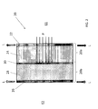
- FIG. 2 shows a cross-section of an acoustic structure 20 for use in a gas turbine engine such as the gas turbine engine 10.
- the acoustic structure 20 may be used on outer ducts, such as a bypass passage of a turbofan engine or fan ducts, for insulating the environment from sounds produced by the gas turbine engine 10.
- the acoustic structure 20 may also be used on thrust reversers, intermediate case, tailcone, jet pipes, fan cases, nacelle inlet, inner bypass ducts to name a few.
- the acoustic structure 20 When in use, the acoustic structure 20 is on one side exposed to a first fluidic environment E1, and on another side to a second fluidic environment E2 of the gas turbine engine 10.
- the first fluidic environment E1 is an environment subject to sounds, such as the sounds originating from the combustor 16 or the fan 12.
- the second fluidic environment E2 is an environment that could potentially be under fire.
- the first fluidic environment E1 is under a pressure higher than that of the second fluidic environment E2.
- the second fluidic environment E2 is at ambient pressure.
- the acoustic structure 20 When in use, the acoustic structure 20 is subject to pressure loads P induced by the higher pressured first fluidic environment E1, and to mechanical loads L originating from components of the engine 10 where the acoustic structure 20 is used.
- the mechanical loads L may be tension or compression or shear or any of the above depending where the acoustic structure 20 is used (e.g. rear mount structure, thrust reverser weight, drag).
- the mechanical loads L are at an angle with respect to the pressure loads P.
- the pressure loads P are normal to the acoustic structure 20.
- the pressure loads P may vary during the course of use of the acoustic structure 20 depending on a regime of the gas turbine engine 10.
- the acoustic structure 20 is, in one embodiment, constructed as a double-layered structure: an noise reduction layer 20a adapted to be in contact with the first fluidic environment E1, and an adjacent fire protector layer 20b adapted to be in contact with the second fluidic environment E2.
- noise reduction one should understand a layer of material or absence thereof that at least diminishes by its presence an amount of sounds.
- fire protector one should understand a layer of material or absence thereof that at least diminishes by its presence the devastating effects associated with a fire on a structure disposed behind the fire protector.
- the noise reduction layer 20a includes an inner wall 22 in contact with the first fluidic environment E1 and a noise reduction 24.
- the fire protector layer 20b includes an outer wall 26 in contact with the second fluidic environment E2, a fire protector 28 and a pressure resisting wall 30 disposed between the fire protector 28 and the noise reduction 24.
- the environments E1 and E2 include, in one embodiment, fluid flow such that the inner wall 22 could be a flow boundary surface for the fluid flow and form part of an aerodynamic surface for guiding the flow of fluid, such as air.
- the inner wall 22 is a perforated structural component of the acoustic structure 20.
- the inner wall 22 is a structural component in that it is a load-bearing wall of the acoustic structure 20, i.e. it carries some of the mechanical loads L.
- the inner wall 22 is perforated to allow the sound pressure to fill dead air cavities in the noise reduction 24 which acts as a sound damping muffler.
- the inner wall 22 could be made of any material resistant enough to support the stresses causes by the mechanical loads L and be damage tolerant with respect to the numerous of holes in it.
- the inner wall 22 is made of carbon fiber epoxy.
- the inner wall 22 is made of aluminum.
- the inner wall 22 is made of glass fibers.
- the outer wall 26 is a non-perforated structural component of the acoustic structure 20 which may protect the pressure resisting wall 30 from fire.
- the outer wall 26 is a structural component in that it is a load-bearing wall of the acoustic structure 20, i.e. it carries some of the mechanical loads L.
- the outer wall 26 could be made of any material resistant enough to support the stresses caused by the mechanical loads L.
- the outer wall 26 may be made of a fire retardant material.
- the outer wall 26 is made of carbon fiber epoxy.
- the outer wall 26 is made of aluminum.
- the outer wall 26 is made of glass fibers.
- the inner and outer walls 22, 26 could or could not be made of a same material.
- the pressure resisting wall 30 is disposed between the inner wall 22 and the outer wall 26.
- the pressure resisting wall 30 is non-perforated in order to support the pressure loading P transmitted through the perforations of the inner wall 22.
- the pressure resisting wall 30 may prevent the outer wall 26 from experiencing the pressure loads P from the first fluidic first fluidic environment E1.
- the pressure resisting wall 30, by protecting the outer wall 26 from the pressure loads P, may at least delay an alteration of the outer wall 26 by a fire in the second fluidic environment E2.
- the pressure resisting wall 30 is thick enough to support the pressure loads P without altering (e.g. buckling or bursting).
- the pressure resisting wall 30 could be made of any material resistant enough to support the stresses caused by the pressure loads P.
- the pressure resisting wall 30 is made of carbon fiber epoxy. In one embodiment, the pressure resisting wall 30 is made of aluminum. In one embodiment, the pressure resisting wall 30 is made of glass fibers. In other embodiments, the pressure resisting wall 30 is a fibre and matrix composite, where the fibres could be, non-exhaustively carbon, glass, ceramic, boron, and where the matrix could be, non-exhaustively, organic polymer, ceramic, thermoset, thermoplastic, or metal.
- the pressure resisting wall 30 may be rigid or flexible.
- the pressure resisting wall 30, inner 22 and outer walls 24 could or could not be made of a same material.
- the pressure resisting wall 30 and the inner wall 22 may be selected in accordance to the noise reduction requirements of the engine 10.
- a space between the inner wall 22 and the pressure resisting wall 30 may be filled with the noise reduction 24.
- the noise reduction 24 attenuate sounds coming from the first fluidic environment E1.
- a thickness of the noise reduction 24 may be determined to absorb the required sound frequency(ies) of the sounds.
- the noise reduction 24 is a honeycomb structure.
- the honeycomb structure includes a plurality of dead air cavities which contributes to the noise reduction.
- the honeycomb structure is made of aluminum, fiberglass or Fibrous, Aramid Base, Phenolic coated.
- a space between the outer wall 26 and The pressure resisting wall 30 may be filled with the fire protector 28.
- the fire protector 28 works as a protection to the pressure resisting wall 30 and the noise reduction 24.
- the fire protector 28 prevents heat transfer through radiation and minimizes the amount of oxygen present in the cavity it fills.
- a thickness of the fire protector 28 may be determined in function of an intensity of a potential fire. A thicker fire protector 28 may be used for more virulent fires.
- the fire protector 28 is a fire retardant.
- the fire protector 28 is a foam.
- the fire protector 28 is an open or a closed cell foam.
- the fire protector 28 is a gap of air.
- the fire protector 28 is an aluminum honeycomb structure.
- the fire protector 28 is a glass honeycomb structure. In one embodiment, the fire protector 28 is a glass bead filled resin. In one embodiment, the fire protector 28 is made of a thermal insulating material. Examples of thermal insulating materials include non-exhaustively balsa wood, silicone rubber, intumescent materials, and fibrous ceramic paper.
- the inner wall 22, outer wall 26, pressure resisting wall 30, noise reduction 24 and fire protector 28 may be glued, riveted or bonded together.
- Inner wall 22, outer wall 26, pressure resisting wall 30, noise reduction 24 and fire protector 28 are shown herein to be parallel to each other with a constant thickness. It is however contemplated that at least one of the inner wall 22, outer wall 26, wall 30, noise reduction 24 and fire protector 28 could be inclined and that depending on the application, the inner wall 22, outer wall 26, pressure resisting wall 30, noise reduction 24 and fire protector 28 could have varying thicknesses.
- the acoustic structure 20 behaves as an integral acoustic structure.
- the outer wall 26 and fire protector 28 protect the pressure resisting wall 30 from direct flame impingement whilst the pressure resisting wall 30 isolates the outer wall 26 from the pressure loading P enabling it to best withstand the flame attack.
- the double-layered acoustic wall is easy to manipulate and adaptable in a variety of environments.
- the above description is meant to be exemplary only, and one skilled in the art will recognize that changes may be made to the embodiments described without departing from the scope of the invention disclosed.
- the gas turbine engine described herein is only one example of engine that may accommodate the acoustic structure.
- the acoustic structure may for example, be used in turborprop engines or any other engines where a fire resistant acoustic structure is needed.
- the acoustic structure is shown here for use in a gas turbine engine, it is contemplated that the acoustic structure could be used in any environment where acoustic insulation on one side of the acoustic structure and fire insulation is required on the other side of the acoustic structure and where one side of the structure is subject to a high pressure. Still other modifications which fall within the scope of the present invention will be apparent to those skilled in the art, in light of a review of this disclosure, and such modifications are intended to fall within the appended claims.
Landscapes
- Engineering & Computer Science (AREA)
- Chemical & Material Sciences (AREA)
- Combustion & Propulsion (AREA)
- Mechanical Engineering (AREA)
- General Engineering & Computer Science (AREA)
- Soundproofing, Sound Blocking, And Sound Damping (AREA)
Abstract
Description
- The application relates generally to aircraft engines and, more particularly, to acoustic structures for use therein.
- Acoustic structures are commonly used in aircraft engines, such as turbofan engines, to reduce a noise impact of the engine to the environment. In order to protect the acoustic structures from the debilitating effects of fire, external blankets, coatings or metallic shields may be added to the acoustic structure. These protections are however structurally parasitic, i.e. they act only to thermally protect the underlying structure and do not play an active role in supporting any structural loading. These fire protections also include additional cost, complicated maintainability and access, and inspectability restriction and complex reparability.
- In one aspect, there is provided an acoustic structure for a gas turbine engine, the acoustic structure comprising: an noise reduction layer including: a perforated inner wall adapted to be in contact with a first fluidic environment, the inner wall being a load-bearing wall of the acoustic structure; and a noise reduction adjacent to the inner wall; and a fire protector layer connected to the noise reduction layer, the fire protector layer including: a non-perforated outer wall adapted to be in contact with a second fluidic environment having potentially a fire, the second fluidic environment being under a pressure lower than a pressure of the first fluidic environment, the outer wall being a load-bearing wall of the acoustic structure; a fire protector adjacent to the outer wall; and a pressure resisting wall disposed between the fire protector and the noise reduction.
- In another aspect, there is provided a gas turbine engine comprising: an acoustic structure separating a first fluidic environment and a second fluidic environment having potentially a fire, the first fluidic environment being under a pressure higher than a pressure of the second fluidic environment, the acoustic structure including: a noise reduction layer including: a perforated inner wall in contact with the first fluidic environment; and a noise reduction adjacent to the inner wall; and a fire protector layer connected to the noise reduction layer, the fire protector layer including: a non-perforated outer wall in contact with the second fluidic environment; a fire protector adjacent to the outer wall; and a pressure resisting wall disposed between the fire protector and the noise reduction, a pressure load being exerted by the first fluidic environment onto the inner wall, the inner wall and the outer wall being subjected to a mechanical load at an angle with the pressure load.
- Reference is now made to the accompanying figures in which:
-
FIG. 1 is a schematic cross-sectional view of a gas turbine engine; and -
FIG. 2 is a schematic cross-sectional view of an acoustic structure for the gas turbine engine ofFIG. 1 . -
FIG. 1 illustrates agas turbine engine 10 generally comprising in serial flow communication afan 12 through which ambient air is propelled, acompressor section 14 for pressurizing the air, acombustor 16 in which the compressed air is mixed with fuel and ignited for generating an annular stream of hot combustion gases, and aturbine section 18 for extracting energy from the combustion gases. -
FIG. 2 shows a cross-section of anacoustic structure 20 for use in a gas turbine engine such as thegas turbine engine 10. Theacoustic structure 20 may be used on outer ducts, such as a bypass passage of a turbofan engine or fan ducts, for insulating the environment from sounds produced by thegas turbine engine 10. Depending on the engine, theacoustic structure 20 may also be used on thrust reversers, intermediate case, tailcone, jet pipes, fan cases, nacelle inlet, inner bypass ducts to name a few. - When in use, the
acoustic structure 20 is on one side exposed to a first fluidic environment E1, and on another side to a second fluidic environment E2 of thegas turbine engine 10. The first fluidic environment E1 is an environment subject to sounds, such as the sounds originating from thecombustor 16 or thefan 12. The second fluidic environment E2 is an environment that could potentially be under fire. The first fluidic environment E1 is under a pressure higher than that of the second fluidic environment E2. In one embodiment, the second fluidic environment E2 is at ambient pressure. - When in use, the
acoustic structure 20 is subject to pressure loads P induced by the higher pressured first fluidic environment E1, and to mechanical loads L originating from components of theengine 10 where theacoustic structure 20 is used. The mechanical loads L may be tension or compression or shear or any of the above depending where theacoustic structure 20 is used (e.g. rear mount structure, thrust reverser weight, drag). The mechanical loads L are at an angle with respect to the pressure loads P. The pressure loads P are normal to theacoustic structure 20. The pressure loads P may vary during the course of use of theacoustic structure 20 depending on a regime of thegas turbine engine 10. - To account for the acoustics and the fire hazards, the
acoustic structure 20 is, in one embodiment, constructed as a double-layered structure: annoise reduction layer 20a adapted to be in contact with the first fluidic environment E1, and an adjacentfire protector layer 20b adapted to be in contact with the second fluidic environment E2. By "noise reduction", one should understand a layer of material or absence thereof that at least diminishes by its presence an amount of sounds. By "fire protector", one should understand a layer of material or absence thereof that at least diminishes by its presence the devastating effects associated with a fire on a structure disposed behind the fire protector. - The
noise reduction layer 20a includes aninner wall 22 in contact with the first fluidic environment E1 and anoise reduction 24. Thefire protector layer 20b includes anouter wall 26 in contact with the second fluidic environment E2, afire protector 28 and apressure resisting wall 30 disposed between thefire protector 28 and thenoise reduction 24. The environments E1 and E2 include, in one embodiment, fluid flow such that theinner wall 22 could be a flow boundary surface for the fluid flow and form part of an aerodynamic surface for guiding the flow of fluid, such as air. - The
inner wall 22 is a perforated structural component of theacoustic structure 20. Theinner wall 22 is a structural component in that it is a load-bearing wall of theacoustic structure 20, i.e. it carries some of the mechanical loads L. Theinner wall 22 is perforated to allow the sound pressure to fill dead air cavities in thenoise reduction 24 which acts as a sound damping muffler. Theinner wall 22 could be made of any material resistant enough to support the stresses causes by the mechanical loads L and be damage tolerant with respect to the numerous of holes in it. In one embodiment, theinner wall 22 is made of carbon fiber epoxy. In one embodiment, theinner wall 22 is made of aluminum. In one embodiment, theinner wall 22 is made of glass fibers. - The
outer wall 26 is a non-perforated structural component of theacoustic structure 20 which may protect thepressure resisting wall 30 from fire. Theouter wall 26 is a structural component in that it is a load-bearing wall of theacoustic structure 20, i.e. it carries some of the mechanical loads L. Theouter wall 26 could be made of any material resistant enough to support the stresses caused by the mechanical loads L. Theouter wall 26 may be made of a fire retardant material. In one embodiment, theouter wall 26 is made of carbon fiber epoxy. In one embodiment, theouter wall 26 is made of aluminum. In one embodiment, theouter wall 26 is made of glass fibers. The inner andouter walls - The
pressure resisting wall 30 is disposed between theinner wall 22 and theouter wall 26. Thepressure resisting wall 30 is non-perforated in order to support the pressure loading P transmitted through the perforations of theinner wall 22. Thepressure resisting wall 30 may prevent theouter wall 26 from experiencing the pressure loads P from the first fluidic first fluidic environment E1. Thepressure resisting wall 30, by protecting theouter wall 26 from the pressure loads P, may at least delay an alteration of theouter wall 26 by a fire in the second fluidic environment E2. Thepressure resisting wall 30 is thick enough to support the pressure loads P without altering (e.g. buckling or bursting). Thepressure resisting wall 30 could be made of any material resistant enough to support the stresses caused by the pressure loads P. In one embodiment, thepressure resisting wall 30 is made of carbon fiber epoxy. In one embodiment, thepressure resisting wall 30 is made of aluminum. In one embodiment, thepressure resisting wall 30 is made of glass fibers. In other embodiments, thepressure resisting wall 30 is a fibre and matrix composite, where the fibres could be, non-exhaustively carbon, glass, ceramic, boron, and where the matrix could be, non-exhaustively, organic polymer, ceramic, thermoset, thermoplastic, or metal. Thepressure resisting wall 30 may be rigid or flexible. Thepressure resisting wall 30, inner 22 andouter walls 24 could or could not be made of a same material. Thepressure resisting wall 30 and theinner wall 22 may be selected in accordance to the noise reduction requirements of theengine 10. - A space between the
inner wall 22 and thepressure resisting wall 30 may be filled with thenoise reduction 24. Thenoise reduction 24 attenuate sounds coming from the first fluidic environment E1. A thickness of thenoise reduction 24 may be determined to absorb the required sound frequency(ies) of the sounds. In one embodiment, thenoise reduction 24 is a honeycomb structure. The honeycomb structure includes a plurality of dead air cavities which contributes to the noise reduction. In one embodiment, the honeycomb structure is made of aluminum, fiberglass or Fibrous, Aramid Base, Phenolic coated. - A space between the
outer wall 26 and Thepressure resisting wall 30 may be filled with thefire protector 28. Thefire protector 28 works as a protection to thepressure resisting wall 30 and thenoise reduction 24. Thefire protector 28 prevents heat transfer through radiation and minimizes the amount of oxygen present in the cavity it fills. A thickness of thefire protector 28 may be determined in function of an intensity of a potential fire. Athicker fire protector 28 may be used for more virulent fires. In one embodiment, thefire protector 28 is a fire retardant. In one embodiment, thefire protector 28 is a foam. In one embodiment, thefire protector 28 is an open or a closed cell foam. In one embodiment, thefire protector 28 is a gap of air. In one embodiment, thefire protector 28 is an aluminum honeycomb structure. In one embodiment, thefire protector 28 is a glass honeycomb structure. In one embodiment, thefire protector 28 is a glass bead filled resin. In one embodiment, thefire protector 28 is made of a thermal insulating material. Examples of thermal insulating materials include non-exhaustively balsa wood, silicone rubber, intumescent materials, and fibrous ceramic paper. - The
inner wall 22,outer wall 26,pressure resisting wall 30,noise reduction 24 andfire protector 28 may be glued, riveted or bonded together.Inner wall 22,outer wall 26,pressure resisting wall 30,noise reduction 24 andfire protector 28 are shown herein to be parallel to each other with a constant thickness. It is however contemplated that at least one of theinner wall 22,outer wall 26,wall 30,noise reduction 24 andfire protector 28 could be inclined and that depending on the application, theinner wall 22,outer wall 26,pressure resisting wall 30,noise reduction 24 andfire protector 28 could have varying thicknesses. - In normal operation, the
acoustic structure 20 behaves as an integral acoustic structure. However, during a fire attack, theouter wall 26 andfire protector 28 protect thepressure resisting wall 30 from direct flame impingement whilst thepressure resisting wall 30 isolates theouter wall 26 from the pressure loading P enabling it to best withstand the flame attack. - By structurally integrating acoustic and fire insulation features into a double-layered construction, parasitic weight is reduced or in some cases eliminated. The double-layered acoustic wall is easy to manipulate and adaptable in a variety of environments.
- The above description is meant to be exemplary only, and one skilled in the art will recognize that changes may be made to the embodiments described without departing from the scope of the invention disclosed. The gas turbine engine described herein is only one example of engine that may accommodate the acoustic structure. The acoustic structure may for example, be used in turborprop engines or any other engines where a fire resistant acoustic structure is needed. Although the acoustic structure is shown here for use in a gas turbine engine, it is contemplated that the acoustic structure could be used in any environment where acoustic insulation on one side of the acoustic structure and fire insulation is required on the other side of the acoustic structure and where one side of the structure is subject to a high pressure. Still other modifications which fall within the scope of the present invention will be apparent to those skilled in the art, in light of a review of this disclosure, and such modifications are intended to fall within the appended claims.
Claims (14)
- An acoustic structure (20) for a gas turbine engine, the acoustic structure (20) comprising:an noise reduction layer (20a) including:a perforated inner wall (22) adapted to be in contact with a first fluidic environment (E1), the inner wall (22) being a load-bearing wall of the acoustic structure (20); anda noise reduction (24) adjacent to the inner wall (22);a fire protector layer (20b) connected to the noise reduction layer (20a), the fire protector layer (20b) including:a non-perforated outer wall (26) adapted to be in contact with a second fluidic environment (E2) having potentially a fire, the second fluidic environment (E2) being under a pressure lower than a pressure of the first fluidic environment, the outer wall (26) being a load-bearing wall of the acoustic structure;a fire protector (28) adjacent to the outer wall (26); anda pressure resisting wall (30) disposed between the fire protector (28) and the noise reduction layer (20a), the pressure resisting wall (30) being adapted to prevent the outer wall (26) from experiencing the pressure from the first fluidic environment (E1).
- A gas turbine engine (10) comprising:an acoustic structure (20) separating a first fluidic environment (E1) and a second fluidic environment (E2) having potentially a fire, the first fluidic environment (E1) being under a pressure higher than a pressure of the second fluidic environment, the acoustic structure (20) including:a noise reduction layer (20a) including:a perforated inner wall (22) in contact with the first fluidic environment (E1); anda noise reduction (24) adjacent to the inner wall (22); anda fire protector layer (20b) connected to the noise reduction layer (20a), the fire protector layer (24) including:a non-perforated outer wall (26) in contact with the second fluidic environment (E2);a fire protector (28) adjacent to the outer wall (26); anda pressure resisting wall (30) disposed between the fire protector (28) and the noise reduction (24),a pressure load being exerted by the first fluidic environment onto the inner wall (22), the inner wall (22) and the outer wall (26) being subjected to a mechanical load at an angle with the pressure load.
- The gas turbine engine as defined in claim 2, wherein the mechanical load is in-plane with at least one of the inner wall (22) and the outer wall (26).
- The acoustic structure or gas turbine engine as defined in any preceding claim, wherein at least one of the inner wall (22), the pressure resisting wall (30), and the outer wall (26) is made of carbon epoxy.
- The acoustic structure or gas turbine engine as defined in any preceding claim, wherein, wherein the fire protector (28) is a gap of air.
- The acoustic structure or gas turbine engine as defined in any of claims 1 to 4, wherein the fire protector (28) is made of closed cell foam.
- The acoustic structure or gas turbine engine as defined in any of claims 1 to 4, wherein the fire protector (28) is made of a thermal insulating material.
- The acoustic structure or gas turbine engine as defined in any preceding claim, wherein the noise reduction (24) includes a honeycomb structure.
- The acoustic structure or gas turbine engine as defined in any preceding claim, wherein the noise reduction (24) absorbs predetermined sound frequency.
- The acoustic structure or gas turbine engine as defined in any preceding claim, wherein the noise reduction layer (24) and the fire protector layer (28) are one of bonded, riveted and glued together.
- The acoustic structure or gas turbine engine as defined in any preceding claim, wherein the fire protector (28) layer is a fire retardant.
- The acoustic structure or gas turbine engine, as defined in any preceding claim, wherein the inner wall (22) and outer wall (26) are parallel.
- The acoustic structure or gas turbine engine, as defined in any preceding claim, wherein the pressure resisting wall (30) is non-perforated.
- A gas turbine engine comprising:an acoustic structure (20) as defined in any of claims 1 or 4 to 13, the acoustic structure (20) separating a first fluidic environment (E1) and a second fluidic environment (E2) having potentially a fire, the first fluidic environment (E1) being under a pressure higher than a pressure of the second fluidic environment.
Applications Claiming Priority (2)
| Application Number | Priority Date | Filing Date | Title |
|---|---|---|---|
| US201361842545P | 2013-07-03 | 2013-07-03 | |
| US14/228,375 US9909501B2 (en) | 2013-07-03 | 2014-03-28 | Acoustic structure for a gas turbine engine |
Publications (2)
| Publication Number | Publication Date |
|---|---|
| EP2821621A1 true EP2821621A1 (en) | 2015-01-07 |
| EP2821621B1 EP2821621B1 (en) | 2017-08-16 |
Family
ID=50980189
Family Applications (1)
| Application Number | Title | Priority Date | Filing Date |
|---|---|---|---|
| EP14173524.1A Active EP2821621B1 (en) | 2013-07-03 | 2014-06-23 | Acoustic structure for a gas turbine engine |
Country Status (2)
| Country | Link |
|---|---|
| US (1) | US9909501B2 (en) |
| EP (1) | EP2821621B1 (en) |
Cited By (1)
| Publication number | Priority date | Publication date | Assignee | Title |
|---|---|---|---|---|
| WO2023233109A1 (en) | 2022-06-03 | 2023-12-07 | Safran | Acoustic panel for an aircraft turbomachine, and associated method and installation |
Families Citing this family (6)
| Publication number | Priority date | Publication date | Assignee | Title |
|---|---|---|---|---|
| US9919500B2 (en) * | 2014-09-29 | 2018-03-20 | Pratt & Whitney Canada Corp. | Inner bypass duct |
| US11466622B2 (en) * | 2018-09-26 | 2022-10-11 | Pratt & Whitney Canada Corp. | Composite aerospace component |
| US10876480B2 (en) * | 2019-02-01 | 2020-12-29 | Pratt & Whitney Canada Corp. | Acoustic structure for gas turbine engine |
| EP3945033B1 (en) * | 2020-07-27 | 2022-09-07 | Airbus Operations (S.A.S.) | Aircraft propulsion unit |
| US12071858B2 (en) * | 2021-10-13 | 2024-08-27 | General Electric Company | Fire retardant engine casing apparatus |
| US20230167774A1 (en) * | 2021-12-01 | 2023-06-01 | Rohr, Inc. | Attachment ring insulator systems, methods, and assemblies |
Citations (6)
| Publication number | Priority date | Publication date | Assignee | Title |
|---|---|---|---|---|
| US4780359A (en) * | 1987-04-03 | 1988-10-25 | Gates Formed-Fibre Products, Inc. | Fire retardent structural textile panel |
| EP0314244A2 (en) * | 1987-10-28 | 1989-05-03 | The Dow Chemical Company | Flame retarding and fire blocking carbonaceous fiber structures and methods of manufacture |
| US4926963A (en) * | 1987-10-06 | 1990-05-22 | Uas Support, Inc. | Sound attenuating laminate for jet aircraft engines |
| EP1862605A2 (en) * | 2006-06-01 | 2007-12-05 | General Electric Company | Thermal-acoustic enclosure |
| US20100024435A1 (en) * | 2006-12-13 | 2010-02-04 | Aircelle | Nacelle for turbofan |
| US20120082808A1 (en) * | 2009-06-15 | 2012-04-05 | Aircelle | Method for installing heat shielding on a fixed internal structure of a jet engine nacelle |
Family Cites Families (10)
| Publication number | Priority date | Publication date | Assignee | Title |
|---|---|---|---|---|
| FR2396868A1 (en) * | 1977-07-07 | 1979-02-02 | Snecma | Combined thermal and noise insulation for jet pipes - has metallic honeycomb covered with layer of porous refractory material in metal casing |
| US4308197A (en) * | 1980-04-21 | 1981-12-29 | Mcdonnell Douglas Corporation | Fire resistant composites |
| ES2030881T3 (en) | 1987-06-19 | 1992-11-16 | Giat Industries | LIGHTWEIGHT AGGLOMERATED PANEL INTENDED FOR THE CONSTRUCTION OF MULTILAYER STRUCTURES RESISTANT TO HITS AND THERMAL AGGRESSIONS. |
| US6511730B1 (en) | 1999-05-27 | 2003-01-28 | Hexcel Corporation | Fire resistant composite panel |
| US7467687B2 (en) | 2004-11-12 | 2008-12-23 | General Electric Company | Thermal—acoustic enclosure |
| JP5380766B2 (en) | 2006-06-05 | 2014-01-08 | 横浜ゴム株式会社 | Honeycomb sandwich panel with soundproofing properties |
| WO2010144951A1 (en) | 2009-06-15 | 2010-12-23 | Stephen Tyralik | Thermal wall panel, building system and methods of use and construction of the same |
| GB0920741D0 (en) * | 2009-11-27 | 2010-01-13 | Rolls Royce Plc | Air flow passage liner |
| US8047329B1 (en) * | 2010-08-13 | 2011-11-01 | Rohr, Inc. | System and method for noise suppression |
| US8733500B1 (en) * | 2012-11-12 | 2014-05-27 | Hexcel Corporation | Acoustic structure with internal thermal regulators |
-
2014
- 2014-03-28 US US14/228,375 patent/US9909501B2/en active Active
- 2014-06-23 EP EP14173524.1A patent/EP2821621B1/en active Active
Patent Citations (6)
| Publication number | Priority date | Publication date | Assignee | Title |
|---|---|---|---|---|
| US4780359A (en) * | 1987-04-03 | 1988-10-25 | Gates Formed-Fibre Products, Inc. | Fire retardent structural textile panel |
| US4926963A (en) * | 1987-10-06 | 1990-05-22 | Uas Support, Inc. | Sound attenuating laminate for jet aircraft engines |
| EP0314244A2 (en) * | 1987-10-28 | 1989-05-03 | The Dow Chemical Company | Flame retarding and fire blocking carbonaceous fiber structures and methods of manufacture |
| EP1862605A2 (en) * | 2006-06-01 | 2007-12-05 | General Electric Company | Thermal-acoustic enclosure |
| US20100024435A1 (en) * | 2006-12-13 | 2010-02-04 | Aircelle | Nacelle for turbofan |
| US20120082808A1 (en) * | 2009-06-15 | 2012-04-05 | Aircelle | Method for installing heat shielding on a fixed internal structure of a jet engine nacelle |
Cited By (2)
| Publication number | Priority date | Publication date | Assignee | Title |
|---|---|---|---|---|
| WO2023233109A1 (en) | 2022-06-03 | 2023-12-07 | Safran | Acoustic panel for an aircraft turbomachine, and associated method and installation |
| FR3136259A1 (en) * | 2022-06-03 | 2023-12-08 | Safran | ACOUSTIC PANEL FOR AN AIRCRAFT TURBOMACHINE, ASSOCIATED METHOD AND INSTALLATION |
Also Published As
| Publication number | Publication date |
|---|---|
| US20150118023A1 (en) | 2015-04-30 |
| US9909501B2 (en) | 2018-03-06 |
| EP2821621B1 (en) | 2017-08-16 |
Similar Documents
| Publication | Publication Date | Title |
|---|---|---|
| US9909501B2 (en) | Acoustic structure for a gas turbine engine | |
| US9032706B2 (en) | Composite fan case with integral containment zone | |
| US8695720B2 (en) | Fireproof systems in aircraft engines | |
| US20120308369A1 (en) | Laminate thermal insulation blanket for aircraft applications and process therefor | |
| CN104769257B (en) | Acoustic construction with internal heat regulator | |
| US9630702B2 (en) | Noise attenuation for an open rotor aircraft propulsion system | |
| JP5237583B2 (en) | Thermoacoustic enclosure and gas turbine engine assembly | |
| RU2531481C2 (en) | Structure blown with exhaust gases and composite unit connected to it, and method to manufacture this unit | |
| US4801496A (en) | Composite member with integrated thermal protection | |
| RU2533936C2 (en) | Method to install thermal protection facility on inner fixed element of turbojet engine nacelle | |
| US10876480B2 (en) | Acoustic structure for gas turbine engine | |
| KR102607648B1 (en) | Enclosure for a gas turbine engine | |
| JP2017503950A (en) | Composite fan inlet blade containment structure | |
| US11466622B2 (en) | Composite aerospace component | |
| US11473297B2 (en) | Multilayered panel for machinery enclosure | |
| CA2852324C (en) | Acoustic structure for a gas turbine engine | |
| US9919500B2 (en) | Inner bypass duct | |
| CN113550934B (en) | Fan housing with crack-stop backplate structure and removable housing box | |
| GB2319589A (en) | Acoustic panel retention |
Legal Events
| Date | Code | Title | Description |
|---|---|---|---|
| PUAI | Public reference made under article 153(3) epc to a published international application that has entered the european phase |
Free format text: ORIGINAL CODE: 0009012 |
|
| 17P | Request for examination filed |
Effective date: 20140623 |
|
| AK | Designated contracting states |
Kind code of ref document: A1 Designated state(s): AL AT BE BG CH CY CZ DE DK EE ES FI FR GB GR HR HU IE IS IT LI LT LU LV MC MK MT NL NO PL PT RO RS SE SI SK SM TR |
|
| AX | Request for extension of the european patent |
Extension state: BA ME |
|
| RIN1 | Information on inventor provided before grant (corrected) |
Inventor name: OLVER, BRYAN Inventor name: CAULFEILD, STEPHEN Inventor name: CHEUNG, KIN-LEUNG |
|
| R17P | Request for examination filed (corrected) |
Effective date: 20150707 |
|
| RBV | Designated contracting states (corrected) |
Designated state(s): AL AT BE BG CH CY CZ DE DK EE ES FI FR GB GR HR HU IE IS IT LI LT LU LV MC MK MT NL NO PL PT RO RS SE SI SK SM TR |
|
| 17Q | First examination report despatched |
Effective date: 20151127 |
|
| GRAP | Despatch of communication of intention to grant a patent |
Free format text: ORIGINAL CODE: EPIDOSNIGR1 |
|
| STAA | Information on the status of an ep patent application or granted ep patent |
Free format text: STATUS: GRANT OF PATENT IS INTENDED |
|
| INTG | Intention to grant announced |
Effective date: 20170222 |
|
| GRAS | Grant fee paid |
Free format text: ORIGINAL CODE: EPIDOSNIGR3 |
|
| GRAA | (expected) grant |
Free format text: ORIGINAL CODE: 0009210 |
|
| STAA | Information on the status of an ep patent application or granted ep patent |
Free format text: STATUS: THE PATENT HAS BEEN GRANTED |
|
| AK | Designated contracting states |
Kind code of ref document: B1 Designated state(s): AL AT BE BG CH CY CZ DE DK EE ES FI FR GB GR HR HU IE IS IT LI LT LU LV MC MK MT NL NO PL PT RO RS SE SI SK SM TR |
|
| REG | Reference to a national code |
Ref country code: GB Ref legal event code: FG4D |
|
| REG | Reference to a national code |
Ref country code: CH Ref legal event code: EP |
|
| REG | Reference to a national code |
Ref country code: IE Ref legal event code: FG4D |
|
| REG | Reference to a national code |
Ref country code: AT Ref legal event code: REF Ref document number: 919295 Country of ref document: AT Kind code of ref document: T Effective date: 20170915 |
|
| REG | Reference to a national code |
Ref country code: DE Ref legal event code: R096 Ref document number: 602014013113 Country of ref document: DE |
|
| REG | Reference to a national code |
Ref country code: NL Ref legal event code: MP Effective date: 20170816 |
|
| REG | Reference to a national code |
Ref country code: LT Ref legal event code: MG4D |
|
| REG | Reference to a national code |
Ref country code: AT Ref legal event code: MK05 Ref document number: 919295 Country of ref document: AT Kind code of ref document: T Effective date: 20170816 |
|
| PG25 | Lapsed in a contracting state [announced via postgrant information from national office to epo] |
Ref country code: NO Free format text: LAPSE BECAUSE OF FAILURE TO SUBMIT A TRANSLATION OF THE DESCRIPTION OR TO PAY THE FEE WITHIN THE PRESCRIBED TIME-LIMIT Effective date: 20171116 Ref country code: AT Free format text: LAPSE BECAUSE OF FAILURE TO SUBMIT A TRANSLATION OF THE DESCRIPTION OR TO PAY THE FEE WITHIN THE PRESCRIBED TIME-LIMIT Effective date: 20170816 Ref country code: LT Free format text: LAPSE BECAUSE OF FAILURE TO SUBMIT A TRANSLATION OF THE DESCRIPTION OR TO PAY THE FEE WITHIN THE PRESCRIBED TIME-LIMIT Effective date: 20170816 Ref country code: NL Free format text: LAPSE BECAUSE OF FAILURE TO SUBMIT A TRANSLATION OF THE DESCRIPTION OR TO PAY THE FEE WITHIN THE PRESCRIBED TIME-LIMIT Effective date: 20170816 Ref country code: FI Free format text: LAPSE BECAUSE OF FAILURE TO SUBMIT A TRANSLATION OF THE DESCRIPTION OR TO PAY THE FEE WITHIN THE PRESCRIBED TIME-LIMIT Effective date: 20170816 Ref country code: SE Free format text: LAPSE BECAUSE OF FAILURE TO SUBMIT A TRANSLATION OF THE DESCRIPTION OR TO PAY THE FEE WITHIN THE PRESCRIBED TIME-LIMIT Effective date: 20170816 |
|
| PG25 | Lapsed in a contracting state [announced via postgrant information from national office to epo] |
Ref country code: GR Free format text: LAPSE BECAUSE OF FAILURE TO SUBMIT A TRANSLATION OF THE DESCRIPTION OR TO PAY THE FEE WITHIN THE PRESCRIBED TIME-LIMIT Effective date: 20171117 Ref country code: PL Free format text: LAPSE BECAUSE OF FAILURE TO SUBMIT A TRANSLATION OF THE DESCRIPTION OR TO PAY THE FEE WITHIN THE PRESCRIBED TIME-LIMIT Effective date: 20170816 Ref country code: IS Free format text: LAPSE BECAUSE OF FAILURE TO SUBMIT A TRANSLATION OF THE DESCRIPTION OR TO PAY THE FEE WITHIN THE PRESCRIBED TIME-LIMIT Effective date: 20171216 Ref country code: BG Free format text: LAPSE BECAUSE OF FAILURE TO SUBMIT A TRANSLATION OF THE DESCRIPTION OR TO PAY THE FEE WITHIN THE PRESCRIBED TIME-LIMIT Effective date: 20171116 Ref country code: RS Free format text: LAPSE BECAUSE OF FAILURE TO SUBMIT A TRANSLATION OF THE DESCRIPTION OR TO PAY THE FEE WITHIN THE PRESCRIBED TIME-LIMIT Effective date: 20170816 Ref country code: ES Free format text: LAPSE BECAUSE OF FAILURE TO SUBMIT A TRANSLATION OF THE DESCRIPTION OR TO PAY THE FEE WITHIN THE PRESCRIBED TIME-LIMIT Effective date: 20170816 Ref country code: LV Free format text: LAPSE BECAUSE OF FAILURE TO SUBMIT A TRANSLATION OF THE DESCRIPTION OR TO PAY THE FEE WITHIN THE PRESCRIBED TIME-LIMIT Effective date: 20170816 |
|
| PG25 | Lapsed in a contracting state [announced via postgrant information from national office to epo] |
Ref country code: CZ Free format text: LAPSE BECAUSE OF FAILURE TO SUBMIT A TRANSLATION OF THE DESCRIPTION OR TO PAY THE FEE WITHIN THE PRESCRIBED TIME-LIMIT Effective date: 20170816 Ref country code: RO Free format text: LAPSE BECAUSE OF FAILURE TO SUBMIT A TRANSLATION OF THE DESCRIPTION OR TO PAY THE FEE WITHIN THE PRESCRIBED TIME-LIMIT Effective date: 20170816 Ref country code: DK Free format text: LAPSE BECAUSE OF FAILURE TO SUBMIT A TRANSLATION OF THE DESCRIPTION OR TO PAY THE FEE WITHIN THE PRESCRIBED TIME-LIMIT Effective date: 20170816 |
|
| REG | Reference to a national code |
Ref country code: DE Ref legal event code: R097 Ref document number: 602014013113 Country of ref document: DE |
|
| PG25 | Lapsed in a contracting state [announced via postgrant information from national office to epo] |
Ref country code: EE Free format text: LAPSE BECAUSE OF FAILURE TO SUBMIT A TRANSLATION OF THE DESCRIPTION OR TO PAY THE FEE WITHIN THE PRESCRIBED TIME-LIMIT Effective date: 20170816 Ref country code: IT Free format text: LAPSE BECAUSE OF FAILURE TO SUBMIT A TRANSLATION OF THE DESCRIPTION OR TO PAY THE FEE WITHIN THE PRESCRIBED TIME-LIMIT Effective date: 20170816 Ref country code: SK Free format text: LAPSE BECAUSE OF FAILURE TO SUBMIT A TRANSLATION OF THE DESCRIPTION OR TO PAY THE FEE WITHIN THE PRESCRIBED TIME-LIMIT Effective date: 20170816 Ref country code: SM Free format text: LAPSE BECAUSE OF FAILURE TO SUBMIT A TRANSLATION OF THE DESCRIPTION OR TO PAY THE FEE WITHIN THE PRESCRIBED TIME-LIMIT Effective date: 20170816 |
|
| REG | Reference to a national code |
Ref country code: FR Ref legal event code: PLFP Year of fee payment: 5 |
|
| PLBE | No opposition filed within time limit |
Free format text: ORIGINAL CODE: 0009261 |
|
| STAA | Information on the status of an ep patent application or granted ep patent |
Free format text: STATUS: NO OPPOSITION FILED WITHIN TIME LIMIT |
|
| 26N | No opposition filed |
Effective date: 20180517 |
|
| PG25 | Lapsed in a contracting state [announced via postgrant information from national office to epo] |
Ref country code: SI Free format text: LAPSE BECAUSE OF FAILURE TO SUBMIT A TRANSLATION OF THE DESCRIPTION OR TO PAY THE FEE WITHIN THE PRESCRIBED TIME-LIMIT Effective date: 20170816 |
|
| REG | Reference to a national code |
Ref country code: CH Ref legal event code: PL |
|
| REG | Reference to a national code |
Ref country code: BE Ref legal event code: MM Effective date: 20180630 |
|
| REG | Reference to a national code |
Ref country code: IE Ref legal event code: MM4A |
|
| PG25 | Lapsed in a contracting state [announced via postgrant information from national office to epo] |
Ref country code: MC Free format text: LAPSE BECAUSE OF FAILURE TO SUBMIT A TRANSLATION OF THE DESCRIPTION OR TO PAY THE FEE WITHIN THE PRESCRIBED TIME-LIMIT Effective date: 20170816 Ref country code: LU Free format text: LAPSE BECAUSE OF NON-PAYMENT OF DUE FEES Effective date: 20180623 |
|
| PG25 | Lapsed in a contracting state [announced via postgrant information from national office to epo] |
Ref country code: IE Free format text: LAPSE BECAUSE OF NON-PAYMENT OF DUE FEES Effective date: 20180623 Ref country code: CH Free format text: LAPSE BECAUSE OF NON-PAYMENT OF DUE FEES Effective date: 20180630 Ref country code: LI Free format text: LAPSE BECAUSE OF NON-PAYMENT OF DUE FEES Effective date: 20180630 |
|
| PG25 | Lapsed in a contracting state [announced via postgrant information from national office to epo] |
Ref country code: BE Free format text: LAPSE BECAUSE OF NON-PAYMENT OF DUE FEES Effective date: 20180630 |
|
| PG25 | Lapsed in a contracting state [announced via postgrant information from national office to epo] |
Ref country code: MT Free format text: LAPSE BECAUSE OF NON-PAYMENT OF DUE FEES Effective date: 20180623 |
|
| PG25 | Lapsed in a contracting state [announced via postgrant information from national office to epo] |
Ref country code: TR Free format text: LAPSE BECAUSE OF FAILURE TO SUBMIT A TRANSLATION OF THE DESCRIPTION OR TO PAY THE FEE WITHIN THE PRESCRIBED TIME-LIMIT Effective date: 20170816 |
|
| PG25 | Lapsed in a contracting state [announced via postgrant information from national office to epo] |
Ref country code: HU Free format text: LAPSE BECAUSE OF FAILURE TO SUBMIT A TRANSLATION OF THE DESCRIPTION OR TO PAY THE FEE WITHIN THE PRESCRIBED TIME-LIMIT; INVALID AB INITIO Effective date: 20140623 Ref country code: PT Free format text: LAPSE BECAUSE OF FAILURE TO SUBMIT A TRANSLATION OF THE DESCRIPTION OR TO PAY THE FEE WITHIN THE PRESCRIBED TIME-LIMIT Effective date: 20170816 |
|
| PG25 | Lapsed in a contracting state [announced via postgrant information from national office to epo] |
Ref country code: HR Free format text: LAPSE BECAUSE OF FAILURE TO SUBMIT A TRANSLATION OF THE DESCRIPTION OR TO PAY THE FEE WITHIN THE PRESCRIBED TIME-LIMIT Effective date: 20170816 Ref country code: MK Free format text: LAPSE BECAUSE OF NON-PAYMENT OF DUE FEES Effective date: 20170816 Ref country code: CY Free format text: LAPSE BECAUSE OF FAILURE TO SUBMIT A TRANSLATION OF THE DESCRIPTION OR TO PAY THE FEE WITHIN THE PRESCRIBED TIME-LIMIT Effective date: 20170816 |
|
| PG25 | Lapsed in a contracting state [announced via postgrant information from national office to epo] |
Ref country code: AL Free format text: LAPSE BECAUSE OF FAILURE TO SUBMIT A TRANSLATION OF THE DESCRIPTION OR TO PAY THE FEE WITHIN THE PRESCRIBED TIME-LIMIT Effective date: 20170816 |
|
| P01 | Opt-out of the competence of the unified patent court (upc) registered |
Effective date: 20230530 |
|
| PGFP | Annual fee paid to national office [announced via postgrant information from national office to epo] |
Ref country code: DE Payment date: 20250520 Year of fee payment: 12 |
|
| PGFP | Annual fee paid to national office [announced via postgrant information from national office to epo] |
Ref country code: GB Payment date: 20250520 Year of fee payment: 12 |
|
| PGFP | Annual fee paid to national office [announced via postgrant information from national office to epo] |
Ref country code: FR Payment date: 20250520 Year of fee payment: 12 |