EP2821594B1 - Airfoil geometry of blade for axial compressor - Google Patents
Airfoil geometry of blade for axial compressor Download PDFInfo
- Publication number
- EP2821594B1 EP2821594B1 EP14167826.8A EP14167826A EP2821594B1 EP 2821594 B1 EP2821594 B1 EP 2821594B1 EP 14167826 A EP14167826 A EP 14167826A EP 2821594 B1 EP2821594 B1 EP 2821594B1
- Authority
- EP
- European Patent Office
- Prior art keywords
- pressure surface
- concave region
- pressure
- blade
- present
- Prior art date
- Legal status (The legal status is an assumption and is not a legal conclusion. Google has not performed a legal analysis and makes no representation as to the accuracy of the status listed.)
- Not-in-force
Links
Images



Classifications
-
- F—MECHANICAL ENGINEERING; LIGHTING; HEATING; WEAPONS; BLASTING
- F04—POSITIVE - DISPLACEMENT MACHINES FOR LIQUIDS; PUMPS FOR LIQUIDS OR ELASTIC FLUIDS
- F04D—NON-POSITIVE-DISPLACEMENT PUMPS
- F04D29/00—Details, component parts, or accessories
- F04D29/26—Rotors specially for elastic fluids
- F04D29/32—Rotors specially for elastic fluids for axial flow pumps
- F04D29/38—Blades
- F04D29/384—Blades characterised by form
-
- F—MECHANICAL ENGINEERING; LIGHTING; HEATING; WEAPONS; BLASTING
- F04—POSITIVE - DISPLACEMENT MACHINES FOR LIQUIDS; PUMPS FOR LIQUIDS OR ELASTIC FLUIDS
- F04D—NON-POSITIVE-DISPLACEMENT PUMPS
- F04D29/00—Details, component parts, or accessories
- F04D29/26—Rotors specially for elastic fluids
- F04D29/32—Rotors specially for elastic fluids for axial flow pumps
- F04D29/321—Rotors specially for elastic fluids for axial flow pumps for axial flow compressors
- F04D29/324—Blades
-
- F—MECHANICAL ENGINEERING; LIGHTING; HEATING; WEAPONS; BLASTING
- F01—MACHINES OR ENGINES IN GENERAL; ENGINE PLANTS IN GENERAL; STEAM ENGINES
- F01D—NON-POSITIVE DISPLACEMENT MACHINES OR ENGINES, e.g. STEAM TURBINES
- F01D5/00—Blades; Blade-carrying members; Heating, heat-insulating, cooling or antivibration means on the blades or the members
- F01D5/12—Blades
- F01D5/14—Form or construction
- F01D5/141—Shape, i.e. outer, aerodynamic form
-
- F—MECHANICAL ENGINEERING; LIGHTING; HEATING; WEAPONS; BLASTING
- F04—POSITIVE - DISPLACEMENT MACHINES FOR LIQUIDS; PUMPS FOR LIQUIDS OR ELASTIC FLUIDS
- F04D—NON-POSITIVE-DISPLACEMENT PUMPS
- F04D21/00—Pump involving supersonic speed of pumped fluids
-
- F—MECHANICAL ENGINEERING; LIGHTING; HEATING; WEAPONS; BLASTING
- F04—POSITIVE - DISPLACEMENT MACHINES FOR LIQUIDS; PUMPS FOR LIQUIDS OR ELASTIC FLUIDS
- F04D—NON-POSITIVE-DISPLACEMENT PUMPS
- F04D29/00—Details, component parts, or accessories
- F04D29/26—Rotors specially for elastic fluids
- F04D29/32—Rotors specially for elastic fluids for axial flow pumps
- F04D29/38—Blades
-
- F—MECHANICAL ENGINEERING; LIGHTING; HEATING; WEAPONS; BLASTING
- F04—POSITIVE - DISPLACEMENT MACHINES FOR LIQUIDS; PUMPS FOR LIQUIDS OR ELASTIC FLUIDS
- F04D—NON-POSITIVE-DISPLACEMENT PUMPS
- F04D29/00—Details, component parts, or accessories
- F04D29/40—Casings; Connections of working fluid
- F04D29/52—Casings; Connections of working fluid for axial pumps
- F04D29/54—Fluid-guiding means, e.g. diffusers
-
- F—MECHANICAL ENGINEERING; LIGHTING; HEATING; WEAPONS; BLASTING
- F04—POSITIVE - DISPLACEMENT MACHINES FOR LIQUIDS; PUMPS FOR LIQUIDS OR ELASTIC FLUIDS
- F04D—NON-POSITIVE-DISPLACEMENT PUMPS
- F04D29/00—Details, component parts, or accessories
- F04D29/40—Casings; Connections of working fluid
- F04D29/52—Casings; Connections of working fluid for axial pumps
- F04D29/54—Fluid-guiding means, e.g. diffusers
- F04D29/541—Specially adapted for elastic fluid pumps
- F04D29/542—Bladed diffusers
- F04D29/544—Blade shapes
-
- Y—GENERAL TAGGING OF NEW TECHNOLOGICAL DEVELOPMENTS; GENERAL TAGGING OF CROSS-SECTIONAL TECHNOLOGIES SPANNING OVER SEVERAL SECTIONS OF THE IPC; TECHNICAL SUBJECTS COVERED BY FORMER USPC CROSS-REFERENCE ART COLLECTIONS [XRACs] AND DIGESTS
- Y02—TECHNOLOGIES OR APPLICATIONS FOR MITIGATION OR ADAPTATION AGAINST CLIMATE CHANGE
- Y02T—CLIMATE CHANGE MITIGATION TECHNOLOGIES RELATED TO TRANSPORTATION
- Y02T50/00—Aeronautics or air transport
- Y02T50/60—Efficient propulsion technologies, e.g. for aircraft
Definitions
- the present invention relates to an airfoil geometry that can be suitably applied to a rotor blade or a stator blade of an axial compressor and, in particular, to an airfoil geometry that can reduce pressure loss by suppressing shock generated on a pressure surface PS (pressure side).
- An airfoil geometry according to the preamble of claim 1 is known from DE 10 2009 013 399 A1 .
- the airfoil geometry of a rotor blade of an axial compressor disclosed in Japanese Patent Application Laid-open No. JP H08-254156 is provided with a concave region, which has a negative curvature, at a position close to the leading edge LE of the suction surface SS, and the position of a bottom portion (a portion that is most depressed) of the concave region is set within a range of 0% to 70% of the chord length from the leading edge LE.
- a plurality of weak compression waves are generated along the suction surface SS (suction side), so that the magnitude of the 1st passage shock can be moderated, deceleration of the airflow velocity is made gentle, and it thus becomes possible to reduce the pressure loss on the suction surface SS of the rotor blade and suppress boundary layer separation.
- the present invention has been accomplished in light of the above-mentioned circumstances, and it is an object thereof to reduce pressure loss by suppressing a shock generated on the pressure surface side of blades forming a blade row of an axial compressor.
- At least part of the concave region of the pressure surface is present within a range of 10% to 20% of the chord length, and it is more preferable that the concave region of the pressure surface is present so as to extend from a position having a chord length of no greater than 10% to a position having a chord length of at least 20%.
- the suction surface of the blade forming the blade row of the axial compressor includes the concave region having a negative curvature, that is formed in the leading edge part of the suction surface, and the flat region having substantially zero curvature, that is continued to the rearward of the concave region, the magnitude of the 1 st passage shock can be moderated, deceleration of the airflow velocity before and after the 1 st passage shock is thereby made gentle, and it is thus possible to reduce pressure loss and suppress boundary layer separation on the suction surface.
- the blade since the blade includes the concave region having a negative curvature in the frontal part on the pressure surface, increase in the airflow velocity in the frontal part on the pressure surface is suppressed, a 2nd passage shock generated to the rear of the concave region is weakened, and it is thus possible to reduce pressure loss on the pressure surface.
- An effect is obtained when the concave region having a negative curvature on the pressure surface of the blade is present in at least part within a range of 10% to 20% of the chord length, and a further effect is obtained when it is present so as to extend from a position having a chord length of no greater than 10% to a position having a chord length of at least 20%.
- FIG. 1 is a diagram showing an airfoil geometry of an embodiment and a curvature distribution on a suction surface SS and a pressure surface PS thereof
- FIG. 2 is a diagram showing an airfoil geometry of a comparative example and a curvature distribution on a suction surface SS and a pressure surface PS thereof
- FIG. 3 is a graph showing pressure distributions in the airfoil geometries of the embodiment and the comparative example
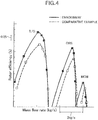
- FIG. 4 is a graph showing rotor efficiency during takeoff, cruising, and maximum climb of the embodiment and the comparative example
- FIG. 5 is a diagram schematically showing 1st and 2nd passage shocks generated in a blade row of a conventional example.
- the airfoil geometry of the present embodiment shown in FIG. 1 is applied to a rotor blade forming a blade row of a rotor of an axial compressor of a jet engine for an aircraft, and includes a suction surface SS (suction side) denoted by a broken line and a pressure surface PS (pressure side) denoted by a solid line. Position in the chord direction on the suction surface SS and the pressure surface PS is expressed as X/C, where C is the chord length and X is the distance measured from a leading edge LE toward a trailing edge TE.
- a convex region is defined as a face having a positive curvature (bulging surface), and a concave region is defined as a face having a negative curvature (depressed surface).
- the suction surface SS denoted by the broken line includes, from the leading edge LE side toward the trailing edge TE side, a suction surface concave region 17, a suction surface flat region 18, and a suction surface convex region 19.
- the suction surface concave region 17 is present in a range from the vicinity of the leading edge LE to a chord position of 20%
- the suction surface flat region 18 having zero curvature is present in a range from a chord position of 20% to a chord position of 40%
- the suction surface convex region 19 is present in a range from a chord position of 40% to the vicinity of the trailing edge TE. This is exactly the same as of the comparative example in FIG. 2 .
- the pressure surface PS denoted by the solid line includes, from the leading edge LE side toward the trailing edge TE side, a first pressure surface concave region 14, a first pressure surface convex region 15, and a second pressure surface concave region 16.
- the first pressure surface concave region 14 is present in a range from a chord position of 7% to a chord position of 22%
- the first pressure surface convex region 15 is present in a range from a chord position of 22% to a chord position of 66%
- the second pressure surface concave region 16 is present in a range from a chord position of 66% to the vicinity of the trailing edge TE.
- FIG. 2 shows the airfoil geometry of a comparative example that is similar to the airfoil geometry disclosed in Japanese Patent Application Laid-open No. JP H08-254156 ; a suction surface SS denoted by a broken line is exactly the same as of the embodiment mentioned above.
- a pressure surface PS denoted by a solid line includes, from the leading edge LE side toward the trailing edge TE side, a pressure surface convex region 20 and a pressure surface concave region 21.
- the pressure surface convex region 20 is present in a range from the vicinity of the leading edge LE to a chord position of 53%
- the pressure surface concave region 21 is present in a range from a chord position of 53% to the vicinity of the trailing edge TE.
- the airfoil geometry of the embodiment shown in FIG. 1 can, by means of the suction surface concave region 17, and the airfoil geometry of the comparative example shown in FIG. 2 can, by means of the suction surface concave region 17, achieve the operational effects of the airfoil geometry disclosed in Japanese Patent Application Laid-open No. JP H08-254156 . That is, by generating a plurality of compression waves, the magnitude of the 1 st passage shock can be moderated and deceleration of the airflow velocity is made gentle, thereby enabling the pressure loss on the suction surface of the rotor blade to be reduced and boundary layer separation to be suppressed.
- the pressure distribution on the suction surface SS denoted by the broken line of the airfoil geometry of the present embodiment substantially coincides with that of the airfoil geometry of the comparative example, and the 1st passage shock is less affected by change on the pressure surface side in curvature shown in the embodiment.
- FIG. 4 shows the dependency of rotor efficiency on the mass flow rate of the axial compressors of the present embodiment and the comparative example in airplanes equipped with jet engines to which they are applied, at times corresponding to takeoff, cruising, and maximum climb.
- the efficiency of the present embodiment is equal to or greater than the efficiency of the comparative example.
- the airfoil geometry of the present invention may be applied not only to a rotor blade of an axial compressor but also to a stator blade of an axial compressor.
- a suction surface (SS) of a blade forming a blade row of an axial compressor includes a concave region (17) having a negative curvature, that is formed in a leading edge part of the suction surface (SS), and a flat region (18) having zero curvature, that is continued to the rearward of the concave region (17), a plurality of compression waves are generated and the magnitude of the 1 st passage shock can be moderated, thus making deceleration of the airflow velocity before and after the 1st passage shock gentle and thereby making it possible to reduce pressure loss and suppress boundary layer separation on the suction surface.
Landscapes
- Engineering & Computer Science (AREA)
- Mechanical Engineering (AREA)
- General Engineering & Computer Science (AREA)
- Physics & Mathematics (AREA)
- Geometry (AREA)
- Fluid Mechanics (AREA)
- Structures Of Non-Positive Displacement Pumps (AREA)
Description
- The present invention relates to an airfoil geometry that can be suitably applied to a rotor blade or a stator blade of an axial compressor and, in particular, to an airfoil geometry that can reduce pressure loss by suppressing shock generated on a pressure surface PS (pressure side).
- An airfoil geometry according to the preamble of
claim 1 is known fromDE 10 2009 013 399 A1 . - When the velocity of an airflow entering a blade row of an axial compressor exceeds the speed of sound, since as shown in
FIG. 5 in an air passage between two adjacent rotor blades of the blade row, one strong shock (1st passage shock) is generated from the leading edge LE of one rotor blade toward the suction surface SS (suction side) of the adjacent rotor blade, the airflow velocity on the suction surface SS of the rotor blade rapidly decreases immediately after the 1 st passage shock, and not only does pressure loss increase, but there is also the problem that the compression efficiency of the compressor is degraded due to boundary layer separation on the suction surface SS of the rotor blade being induced by the 1st passage shock. - In order to solve such a problem, the airfoil geometry of a rotor blade of an axial compressor disclosed in Japanese Patent Application Laid-open No.
JP H08-254156 - However, in the arrangement disclosed in Japanese Patent Application Laid-open
JP H08-254156 - The present invention has been accomplished in light of the above-mentioned circumstances, and it is an object thereof to reduce pressure loss by suppressing a shock generated on the pressure surface side of blades forming a blade row of an axial compressor.
- In order to attain the above object, in accordance with the present invention, there is proposed an airfoil geometry for an axial compressor with the features of
claim 1, namely an airfoil geometry comprising a blade for forming a blade row of an axial compressor having a suction surface and a pressure surface, the suction surface including a concave region having a negative curvature, that is formed in a leading edge part of the suction surface, a concave region having a negative curvature in a frontal part on the pressure surface and a flat region having substantially zero curvature, that is continued to the rearward of the concave region. It is preferable that at least part of the concave region of the pressure surface is present within a range of 10% to 20% of the chord length, and it is more preferable that the concave region of the pressure surface is present so as to extend from a position having a chord length of no greater than 10% to a position having a chord length of at least 20%. - In accordance with the above arrangement, since the suction surface of the blade forming the blade row of the axial compressor includes the concave region having a negative curvature, that is formed in the leading edge part of the suction surface, and the flat region having substantially zero curvature, that is continued to the rearward of the concave region, the magnitude of the 1 st passage shock can be moderated, deceleration of the airflow velocity before and after the 1 st passage shock is thereby made gentle, and it is thus possible to reduce pressure loss and suppress boundary layer separation on the suction surface.
- In addition thereto, since the blade includes the concave region having a negative curvature in the frontal part on the pressure surface, increase in the airflow velocity in the frontal part on the pressure surface is suppressed, a 2nd passage shock generated to the rear of the concave region is weakened, and it is thus possible to reduce pressure loss on the pressure surface.
- An effect is obtained when the concave region having a negative curvature on the pressure surface of the blade is present in at least part within a range of 10% to 20% of the chord length, and a further effect is obtained when it is present so as to extend from a position having a chord length of no greater than 10% to a position having a chord length of at least 20%.
- The above and other objects, features, and advantages of the present invention will become apparent from an explanation of preferred embodiments that are described in detail below by reference to the attached drawings.
- A mode for carrying out the present invention is explained below by reference to the attached drawings.
-
FIG. 1 is a diagram showing an airfoil geometry of an embodiment and a curvature distribution on a suction surface SS and a pressure surface PS thereof,FIG. 2 is a diagram showing an airfoil geometry of a comparative example and a curvature distribution on a suction surface SS and a pressure surface PS thereof,FIG. 3 is a graph showing pressure distributions in the airfoil geometries of the embodiment and the comparative example,FIG. 4 is a graph showing rotor efficiency during takeoff, cruising, and maximum climb of the embodiment and the comparative example, andFIG. 5 is a diagram schematically showing 1st and 2nd passage shocks generated in a blade row of a conventional example. - The airfoil geometry of the present embodiment shown in
FIG. 1 is applied to a rotor blade forming a blade row of a rotor of an axial compressor of a jet engine for an aircraft, and includes a suction surface SS (suction side) denoted by a broken line and a pressure surface PS (pressure side) denoted by a solid line. Position in the chord direction on the suction surface SS and the pressure surface PS is expressed as X/C, where C is the chord length and X is the distance measured from a leading edge LE toward a trailing edge TE. In the present specification, a convex region is defined as a face having a positive curvature (bulging surface), and a concave region is defined as a face having a negative curvature (depressed surface). - As is clear from
FIG. 1 , the suction surface SS denoted by the broken line includes, from the leading edge LE side toward the trailing edge TE side, a suction surfaceconcave region 17, a suction surfaceflat region 18, and a suction surface convexregion 19. The suction surfaceconcave region 17 is present in a range from the vicinity of the leading edge LE to a chord position of 20%, the suction surfaceflat region 18 having zero curvature is present in a range from a chord position of 20% to a chord position of 40%, and the suctionsurface convex region 19 is present in a range from a chord position of 40% to the vicinity of the trailing edge TE. This is exactly the same as of the comparative example inFIG. 2 . - Furthermore, the pressure surface PS denoted by the solid line includes, from the leading edge LE side toward the trailing edge TE side, a first pressure surface
concave region 14, a first pressure surface convexregion 15, and a second pressure surfaceconcave region 16. The first pressure surfaceconcave region 14 is present in a range from a chord position of 7% to a chord position of 22%, the first pressuresurface convex region 15 is present in a range from a chord position of 22% to a chord position of 66%, and the second pressure surfaceconcave region 16 is present in a range from a chord position of 66% to the vicinity of the trailing edge TE. -
FIG. 2 shows the airfoil geometry of a comparative example that is similar to the airfoil geometry disclosed in Japanese Patent Application Laid-open No.JP H08-254156 - Furthermore, a pressure surface PS denoted by a solid line includes, from the leading edge LE side toward the trailing edge TE side, a pressure surface convex
region 20 and a pressure surfaceconcave region 21. The pressuresurface convex region 20 is present in a range from the vicinity of the leading edge LE to a chord position of 53%, and the pressure surfaceconcave region 21 is present in a range from a chord position of 53% to the vicinity of the trailing edge TE. - The airfoil geometry of the embodiment shown in
FIG. 1 can, by means of the suction surfaceconcave region 17, and the airfoil geometry of the comparative example shown inFIG. 2 can, by means of the suction surfaceconcave region 17, achieve the operational effects of the airfoil geometry disclosed in Japanese Patent Application Laid-open No.JP H08-254156 - As is also clear from
FIG. 3 , it can be understood that the pressure distribution on the suction surface SS denoted by the broken line of the airfoil geometry of the present embodiment substantially coincides with that of the airfoil geometry of the comparative example, and the 1st passage shock is less affected by change on the pressure surface side in curvature shown in the embodiment. - On the other hand, when the geometry of the pressure surface PS is compared, as shown in
FIG. 2 the frontal part of the pressure surface PS of the airfoil geometry of the comparative example is occupied by the pressure surface convexregion 20, and no concave region is present thereon. However, as shown by the region enclosed by an ellipse inFIG. 1 , since the first pressure surfaceconcave region 14 is formed so as to extend from a chord position of 7% to a chord position of 22% in the frontal part on the pressure surface PS of the airfoil geometry of the present embodiment, it becomes possible to decelerate the airflow velocity on the pressure surface PS by means of the first pressure surfaceconcave region 14. - In the airfoil geometry of the comparative example, since the airflow velocity on the pressure surface PS is accelerated by means of the pressure surface convex
region 20, a large 2nd passage shock is generated in the pressure surface convexregion 20, thus giving rise to the problem that the pressure loss increases. However, in the airfoil geometry of the present embodiment, since the first pressure surfaceconcave region 14, which decelerates the airflow velocity, is provided in front of the first pressure surface convexregion 15, which accelerates the airflow velocity on the pressure surface PS, it is possible to lower the peak value of the airflow velocity on the pressure surface PS, thus weakening the 2nd passage shock generated in the first pressure surface convexregion 15, and thereby reducing pressure loss due to the 2nd passage shock. - As shown by the regions enclosed by circles in the pressure distribution on the pressure surface PS of
FIG. 3 , it can be understood that in the comparative example a steep change in pressure occurs due to a large 2nd passage shock, whereas in the embodiment the change in pressure is reduced due to the 2nd passage shock being weakened. -
FIG. 4 shows the dependency of rotor efficiency on the mass flow rate of the axial compressors of the present embodiment and the comparative example in airplanes equipped with jet engines to which they are applied, at times corresponding to takeoff, cruising, and maximum climb. As is clear from the figure, it can be understood that for all mass flow rates, the efficiency of the present embodiment is equal to or greater than the efficiency of the comparative example. - An embodiment of the present invention is explained above, but the present invention may be modified in a variety of ways as long as the modifications do not depart from the scope of the present invention as defined in the appended claims.
- For example, the airfoil geometry of the present invention may be applied not only to a rotor blade of an axial compressor but also to a stator blade of an axial compressor.
- It is an object of the present invention to reduce pressure loss by suppressing a shock generated on a pressure surface side of blades forming a blade row of an axial compressor. Since a suction surface (SS) of a blade forming a blade row of an axial compressor includes a concave region (17) having a negative curvature, that is formed in a leading edge part of the suction surface (SS), and a flat region (18) having zero curvature, that is continued to the rearward of the concave region (17), a plurality of compression waves are generated and the magnitude of the 1 st passage shock can be moderated, thus making deceleration of the airflow velocity before and after the 1st passage shock gentle and thereby making it possible to reduce pressure loss and suppress boundary layer separation on the suction surface. In addition thereto, due to the blade being provided with a concave region (14) having a negative curvature in a frontal part on the pressure surface (PS), increase in the airflow velocity in the frontal part on the pressure surface (PS) is suppressed, thus weakening a 2nd passage shock generated on the pressure surface (PS) and thereby enabling pressure loss to be reduced. A further effect is obtained when the concave region (14) is present so as to extend from a position having a chord length of no greater than 10% to a position having at least 20%.
Claims (3)
- An airfoil geometry for an axial compressor, comprising- a blade for forming a blade row of an axial compressor having• a suction surface (SS); and• a pressure surface (PS);- the suction surface (SS) including a concave region (17) having a negative curvature, that is formed in a leading edge part of the suction surface (SS), and- a concave region (14) having a negative curvature in a frontal part on the pressure surface (PS),- characterized in that the blade comprises a flat region (18) having zero curvature, that is continued to the rearward of the concave region (17).
- The airfoil geometry for an axial compressor according to Claim 1, wherein at least part of the concave region (14) of the pressure surface (PS) is present within a range of 10% to 20% of the chord length.
- The airfoil geometry for an axial compressor according to Claim 2, wherein the concave region (14) of the pressure surface (PS) is present so as to extend from a position having a chord length of no greater than 10% to a position having a chord length of at least 20%.
Applications Claiming Priority (1)
| Application Number | Priority Date | Filing Date | Title |
|---|---|---|---|
| DE102013209966.5A DE102013209966A1 (en) | 2013-05-28 | 2013-05-28 | Profile geometry of a wing for an axial compressor |
Publications (3)
| Publication Number | Publication Date |
|---|---|
| EP2821594A2 EP2821594A2 (en) | 2015-01-07 |
| EP2821594A3 EP2821594A3 (en) | 2015-04-15 |
| EP2821594B1 true EP2821594B1 (en) | 2017-08-02 |
Family
ID=50679949
Family Applications (1)
| Application Number | Title | Priority Date | Filing Date |
|---|---|---|---|
| EP14167826.8A Not-in-force EP2821594B1 (en) | 2013-05-28 | 2014-05-12 | Airfoil geometry of blade for axial compressor |
Country Status (4)
| Country | Link |
|---|---|
| US (1) | US9752589B2 (en) |
| EP (1) | EP2821594B1 (en) |
| JP (1) | JP2014231832A (en) |
| DE (1) | DE102013209966A1 (en) |
Families Citing this family (4)
| Publication number | Priority date | Publication date | Assignee | Title |
|---|---|---|---|---|
| EP3205885A1 (en) * | 2016-02-10 | 2017-08-16 | Siemens Aktiengesellschaft | Compressor rotor blade and method for profiling said blade |
| US10774650B2 (en) * | 2017-10-12 | 2020-09-15 | Raytheon Technologies Corporation | Gas turbine engine airfoil |
| US11193377B2 (en) | 2019-11-26 | 2021-12-07 | General Electric Company | Turbomachine airfoil to reduce laminar separation |
| CN113148222B (en) * | 2021-05-24 | 2023-01-31 | 北京航空航天大学 | Close curved surface wave-rider positive design method suitable for complex leading edge shape |
Family Cites Families (22)
| Publication number | Priority date | Publication date | Assignee | Title |
|---|---|---|---|---|
| US2935246A (en) * | 1949-06-02 | 1960-05-03 | Onera (Off Nat Aerospatiale) | Shock wave compressors, especially for use in connection with continuous flow engines for aircraft |
| FR1256045A (en) * | 1960-02-03 | 1961-03-17 | Improvements to axial compressor wheels working at transonic and supersonic speeds | |
| FR2165704B1 (en) * | 1971-10-27 | 1974-02-15 | Piret Daniel | |
| US4123196A (en) * | 1976-11-01 | 1978-10-31 | General Electric Company | Supersonic compressor with off-design performance improvement |
| DE2712717A1 (en) * | 1977-03-23 | 1978-09-28 | Ver Flugtechnische Werke | ABOVE CRITICAL WING PROFILE |
| JPH08121390A (en) * | 1994-10-25 | 1996-05-14 | Ishikawajima Harima Heavy Ind Co Ltd | Compressor airfoil for high speed fluids |
| JPH08254156A (en) * | 1995-03-17 | 1996-10-01 | Senshin Zairyo Riyou Gas Jienereeta Kenkyusho:Kk | Axial compressor rotor blades |
| JPH09256997A (en) * | 1996-03-25 | 1997-09-30 | Senshin Zairyo Riyou Gas Jienereeta Kenkyusho:Kk | Axial compressor rotor blades |
| JP2954539B2 (en) * | 1996-08-09 | 1999-09-27 | 川崎重工業株式会社 | Tandem cascade |
| GB9828447D0 (en) * | 1998-12-24 | 1999-02-17 | Secr Defence Brit | Wing trailing edge |
| JP2001271602A (en) * | 2000-03-27 | 2001-10-05 | Honda Motor Co Ltd | Gas turbine engine |
| US6358012B1 (en) * | 2000-05-01 | 2002-03-19 | United Technologies Corporation | High efficiency turbomachinery blade |
| DE10027084C2 (en) * | 2000-05-31 | 2002-07-18 | Honda Motor Co Ltd | Guide vane and guide vane cascade for an axial compressor |
| JP4563653B2 (en) * | 2003-03-25 | 2010-10-13 | 本田技研工業株式会社 | High turning and high transonic wings |
| US6905309B2 (en) * | 2003-08-28 | 2005-06-14 | General Electric Company | Methods and apparatus for reducing vibrations induced to compressor airfoils |
| EP1607573B2 (en) * | 2004-06-02 | 2012-10-03 | Rolls-Royce Deutschland Ltd & Co KG | Compressor blade with reduced aerodynamic vibration induction |
| GB0428368D0 (en) * | 2004-12-24 | 2005-02-02 | Rolls Royce Plc | A composite blade |
| US20080118362A1 (en) * | 2006-11-16 | 2008-05-22 | Siemens Power Generation, Inc. | Transonic compressor rotors with non-monotonic meanline angle distributions |
| DE102008036294A1 (en) * | 2008-08-04 | 2010-02-11 | Mtu Aero Engines Gmbh | Axial compressor with compressor grille |
| DE102009013399A1 (en) * | 2009-03-16 | 2010-09-23 | Mtu Aero Engines Gmbh | Tandem blade design |
| US8393872B2 (en) * | 2009-10-23 | 2013-03-12 | General Electric Company | Turbine airfoil |
| GB201003084D0 (en) * | 2010-02-24 | 2010-04-14 | Rolls Royce Plc | An aerofoil |
-
2013
- 2013-05-28 DE DE102013209966.5A patent/DE102013209966A1/en not_active Withdrawn
-
2014
- 2014-03-25 JP JP2014062376A patent/JP2014231832A/en active Pending
- 2014-05-12 EP EP14167826.8A patent/EP2821594B1/en not_active Not-in-force
- 2014-05-15 US US14/278,048 patent/US9752589B2/en active Active
Non-Patent Citations (1)
| Title |
|---|
| None * |
Also Published As
| Publication number | Publication date |
|---|---|
| JP2014231832A (en) | 2014-12-11 |
| DE102013209966A1 (en) | 2014-12-04 |
| US20140356156A1 (en) | 2014-12-04 |
| US9752589B2 (en) | 2017-09-05 |
| EP2821594A3 (en) | 2015-04-15 |
| EP2821594A2 (en) | 2015-01-07 |
Similar Documents
| Publication | Publication Date | Title |
|---|---|---|
| EP2360377B1 (en) | A compressor aerofoil | |
| US9835044B2 (en) | Turbomachine comprising a plurality of fixed radial blades mounted upstream of the fan | |
| US8118560B2 (en) | Blade | |
| US9670783B2 (en) | Blade of a turbomachine, having passive boundary layer control | |
| JPH06305492A (en) | Rotor blade | |
| EP2402250B1 (en) | Pylon for attaching a gas turbine engine | |
| US9752589B2 (en) | Airfoil geometry of blade for axial compressor | |
| JP5342637B2 (en) | Airfoil for an axial compressor that enables low loss in the low Reynolds number region | |
| JPWO2012132420A1 (en) | Aircraft high lift device | |
| US11598348B2 (en) | Fan blade comprising a thin shield and a stiffener | |
| EP1371550B1 (en) | Trailing edge shape of laminar-flow airfoil | |
| DK201170430A (en) | Blade for a rotor of a wind turbine and a wind turbine | |
| US6802474B2 (en) | Advanced high turning compressor airfoils | |
| US7056089B2 (en) | High-turning and high-transonic blade | |
| WO2011098807A1 (en) | Apparatus and Method for Aerodynamic Drag Reduction | |
| US12227286B2 (en) | Method of and transonically operating aircraft having devices for suppressing aeroelastic instabilities | |
| US5318249A (en) | Curled trailing edge airfoil | |
| US11873095B2 (en) | Leading-edge component for an aircraft | |
| US9567862B2 (en) | Vane profile for axial-flow compressor | |
| US11585223B2 (en) | Gas turbine blade arrangement | |
| KR200406520Y1 (en) | Ship propeller with cavitation reduction structure | |
| CN111003143B (en) | Wings of aircraft and aircraft including such wings | |
| JP2022182285A (en) | Leading edge high-lift device, wing and aircraft, and buffer member | |
| JP2003182693A (en) | Transonic aircraft |
Legal Events
| Date | Code | Title | Description |
|---|---|---|---|
| PUAI | Public reference made under article 153(3) epc to a published international application that has entered the european phase |
Free format text: ORIGINAL CODE: 0009012 |
|
| 17P | Request for examination filed |
Effective date: 20140512 |
|
| AK | Designated contracting states |
Kind code of ref document: A2 Designated state(s): AL AT BE BG CH CY CZ DE DK EE ES FI FR GB GR HR HU IE IS IT LI LT LU LV MC MK MT NL NO PL PT RO RS SE SI SK SM TR |
|
| AX | Request for extension of the european patent |
Extension state: BA ME |
|
| REG | Reference to a national code |
Ref country code: DE Ref legal event code: R079 Ref document number: 602014012429 Country of ref document: DE Free format text: PREVIOUS MAIN CLASS: F01D0005280000 Ipc: F01D0005140000 |
|
| PUAL | Search report despatched |
Free format text: ORIGINAL CODE: 0009013 |
|
| AK | Designated contracting states |
Kind code of ref document: A3 Designated state(s): AL AT BE BG CH CY CZ DE DK EE ES FI FR GB GR HR HU IE IS IT LI LT LU LV MC MK MT NL NO PL PT RO RS SE SI SK SM TR |
|
| AX | Request for extension of the european patent |
Extension state: BA ME |
|
| RIC1 | Information provided on ipc code assigned before grant |
Ipc: F01D 5/14 20060101AFI20150311BHEP Ipc: F04D 29/32 20060101ALI20150311BHEP Ipc: F04D 29/54 20060101ALI20150311BHEP |
|
| 17Q | First examination report despatched |
Effective date: 20160217 |
|
| GRAP | Despatch of communication of intention to grant a patent |
Free format text: ORIGINAL CODE: EPIDOSNIGR1 |
|
| INTG | Intention to grant announced |
Effective date: 20170222 |
|
| GRAS | Grant fee paid |
Free format text: ORIGINAL CODE: EPIDOSNIGR3 |
|
| GRAA | (expected) grant |
Free format text: ORIGINAL CODE: 0009210 |
|
| AK | Designated contracting states |
Kind code of ref document: B1 Designated state(s): AL AT BE BG CH CY CZ DE DK EE ES FI FR GB GR HR HU IE IS IT LI LT LU LV MC MK MT NL NO PL PT RO RS SE SI SK SM TR |
|
| REG | Reference to a national code |
Ref country code: CH Ref legal event code: EP Ref country code: AT Ref legal event code: REF Ref document number: 914708 Country of ref document: AT Kind code of ref document: T Effective date: 20170815 |
|
| REG | Reference to a national code |
Ref country code: IE Ref legal event code: FG4D |
|
| REG | Reference to a national code |
Ref country code: DE Ref legal event code: R096 Ref document number: 602014012429 Country of ref document: DE |
|
| REG | Reference to a national code |
Ref country code: NL Ref legal event code: MP Effective date: 20170802 |
|
| REG | Reference to a national code |
Ref country code: AT Ref legal event code: MK05 Ref document number: 914708 Country of ref document: AT Kind code of ref document: T Effective date: 20170802 |
|
| REG | Reference to a national code |
Ref country code: LT Ref legal event code: MG4D |
|
| PG25 | Lapsed in a contracting state [announced via postgrant information from national office to epo] |
Ref country code: AT Free format text: LAPSE BECAUSE OF FAILURE TO SUBMIT A TRANSLATION OF THE DESCRIPTION OR TO PAY THE FEE WITHIN THE PRESCRIBED TIME-LIMIT Effective date: 20170802 Ref country code: NO Free format text: LAPSE BECAUSE OF FAILURE TO SUBMIT A TRANSLATION OF THE DESCRIPTION OR TO PAY THE FEE WITHIN THE PRESCRIBED TIME-LIMIT Effective date: 20171102 Ref country code: NL Free format text: LAPSE BECAUSE OF FAILURE TO SUBMIT A TRANSLATION OF THE DESCRIPTION OR TO PAY THE FEE WITHIN THE PRESCRIBED TIME-LIMIT Effective date: 20170802 Ref country code: SE Free format text: LAPSE BECAUSE OF FAILURE TO SUBMIT A TRANSLATION OF THE DESCRIPTION OR TO PAY THE FEE WITHIN THE PRESCRIBED TIME-LIMIT Effective date: 20170802 Ref country code: HR Free format text: LAPSE BECAUSE OF FAILURE TO SUBMIT A TRANSLATION OF THE DESCRIPTION OR TO PAY THE FEE WITHIN THE PRESCRIBED TIME-LIMIT Effective date: 20170802 Ref country code: FI Free format text: LAPSE BECAUSE OF FAILURE TO SUBMIT A TRANSLATION OF THE DESCRIPTION OR TO PAY THE FEE WITHIN THE PRESCRIBED TIME-LIMIT Effective date: 20170802 Ref country code: LT Free format text: LAPSE BECAUSE OF FAILURE TO SUBMIT A TRANSLATION OF THE DESCRIPTION OR TO PAY THE FEE WITHIN THE PRESCRIBED TIME-LIMIT Effective date: 20170802 |
|
| PG25 | Lapsed in a contracting state [announced via postgrant information from national office to epo] |
Ref country code: GR Free format text: LAPSE BECAUSE OF FAILURE TO SUBMIT A TRANSLATION OF THE DESCRIPTION OR TO PAY THE FEE WITHIN THE PRESCRIBED TIME-LIMIT Effective date: 20171103 Ref country code: LV Free format text: LAPSE BECAUSE OF FAILURE TO SUBMIT A TRANSLATION OF THE DESCRIPTION OR TO PAY THE FEE WITHIN THE PRESCRIBED TIME-LIMIT Effective date: 20170802 Ref country code: PL Free format text: LAPSE BECAUSE OF FAILURE TO SUBMIT A TRANSLATION OF THE DESCRIPTION OR TO PAY THE FEE WITHIN THE PRESCRIBED TIME-LIMIT Effective date: 20170802 Ref country code: BG Free format text: LAPSE BECAUSE OF FAILURE TO SUBMIT A TRANSLATION OF THE DESCRIPTION OR TO PAY THE FEE WITHIN THE PRESCRIBED TIME-LIMIT Effective date: 20171102 Ref country code: RS Free format text: LAPSE BECAUSE OF FAILURE TO SUBMIT A TRANSLATION OF THE DESCRIPTION OR TO PAY THE FEE WITHIN THE PRESCRIBED TIME-LIMIT Effective date: 20170802 Ref country code: IS Free format text: LAPSE BECAUSE OF FAILURE TO SUBMIT A TRANSLATION OF THE DESCRIPTION OR TO PAY THE FEE WITHIN THE PRESCRIBED TIME-LIMIT Effective date: 20171202 Ref country code: ES Free format text: LAPSE BECAUSE OF FAILURE TO SUBMIT A TRANSLATION OF THE DESCRIPTION OR TO PAY THE FEE WITHIN THE PRESCRIBED TIME-LIMIT Effective date: 20170802 |
|
| PG25 | Lapsed in a contracting state [announced via postgrant information from national office to epo] |
Ref country code: CZ Free format text: LAPSE BECAUSE OF FAILURE TO SUBMIT A TRANSLATION OF THE DESCRIPTION OR TO PAY THE FEE WITHIN THE PRESCRIBED TIME-LIMIT Effective date: 20170802 Ref country code: RO Free format text: LAPSE BECAUSE OF FAILURE TO SUBMIT A TRANSLATION OF THE DESCRIPTION OR TO PAY THE FEE WITHIN THE PRESCRIBED TIME-LIMIT Effective date: 20170802 Ref country code: DK Free format text: LAPSE BECAUSE OF FAILURE TO SUBMIT A TRANSLATION OF THE DESCRIPTION OR TO PAY THE FEE WITHIN THE PRESCRIBED TIME-LIMIT Effective date: 20170802 |
|
| REG | Reference to a national code |
Ref country code: DE Ref legal event code: R097 Ref document number: 602014012429 Country of ref document: DE |
|
| PG25 | Lapsed in a contracting state [announced via postgrant information from national office to epo] |
Ref country code: IT Free format text: LAPSE BECAUSE OF FAILURE TO SUBMIT A TRANSLATION OF THE DESCRIPTION OR TO PAY THE FEE WITHIN THE PRESCRIBED TIME-LIMIT Effective date: 20170802 Ref country code: SK Free format text: LAPSE BECAUSE OF FAILURE TO SUBMIT A TRANSLATION OF THE DESCRIPTION OR TO PAY THE FEE WITHIN THE PRESCRIBED TIME-LIMIT Effective date: 20170802 Ref country code: SM Free format text: LAPSE BECAUSE OF FAILURE TO SUBMIT A TRANSLATION OF THE DESCRIPTION OR TO PAY THE FEE WITHIN THE PRESCRIBED TIME-LIMIT Effective date: 20170802 Ref country code: EE Free format text: LAPSE BECAUSE OF FAILURE TO SUBMIT A TRANSLATION OF THE DESCRIPTION OR TO PAY THE FEE WITHIN THE PRESCRIBED TIME-LIMIT Effective date: 20170802 |
|
| PLBE | No opposition filed within time limit |
Free format text: ORIGINAL CODE: 0009261 |
|
| STAA | Information on the status of an ep patent application or granted ep patent |
Free format text: STATUS: NO OPPOSITION FILED WITHIN TIME LIMIT |
|
| 26N | No opposition filed |
Effective date: 20180503 |
|
| PG25 | Lapsed in a contracting state [announced via postgrant information from national office to epo] |
Ref country code: SI Free format text: LAPSE BECAUSE OF FAILURE TO SUBMIT A TRANSLATION OF THE DESCRIPTION OR TO PAY THE FEE WITHIN THE PRESCRIBED TIME-LIMIT Effective date: 20170802 |
|
| REG | Reference to a national code |
Ref country code: CH Ref legal event code: PL |
|
| REG | Reference to a national code |
Ref country code: BE Ref legal event code: MM Effective date: 20180531 |
|
| PG25 | Lapsed in a contracting state [announced via postgrant information from national office to epo] |
Ref country code: MC Free format text: LAPSE BECAUSE OF FAILURE TO SUBMIT A TRANSLATION OF THE DESCRIPTION OR TO PAY THE FEE WITHIN THE PRESCRIBED TIME-LIMIT Effective date: 20170802 |
|
| REG | Reference to a national code |
Ref country code: IE Ref legal event code: MM4A |
|
| PG25 | Lapsed in a contracting state [announced via postgrant information from national office to epo] |
Ref country code: LI Free format text: LAPSE BECAUSE OF NON-PAYMENT OF DUE FEES Effective date: 20180531 Ref country code: CH Free format text: LAPSE BECAUSE OF NON-PAYMENT OF DUE FEES Effective date: 20180531 |
|
| PG25 | Lapsed in a contracting state [announced via postgrant information from national office to epo] |
Ref country code: LU Free format text: LAPSE BECAUSE OF NON-PAYMENT OF DUE FEES Effective date: 20180512 |
|
| PG25 | Lapsed in a contracting state [announced via postgrant information from national office to epo] |
Ref country code: IE Free format text: LAPSE BECAUSE OF NON-PAYMENT OF DUE FEES Effective date: 20180512 Ref country code: FR Free format text: LAPSE BECAUSE OF NON-PAYMENT OF DUE FEES Effective date: 20180531 |
|
| PG25 | Lapsed in a contracting state [announced via postgrant information from national office to epo] |
Ref country code: BE Free format text: LAPSE BECAUSE OF NON-PAYMENT OF DUE FEES Effective date: 20180531 |
|
| PG25 | Lapsed in a contracting state [announced via postgrant information from national office to epo] |
Ref country code: MT Free format text: LAPSE BECAUSE OF NON-PAYMENT OF DUE FEES Effective date: 20180512 |
|
| PG25 | Lapsed in a contracting state [announced via postgrant information from national office to epo] |
Ref country code: TR Free format text: LAPSE BECAUSE OF FAILURE TO SUBMIT A TRANSLATION OF THE DESCRIPTION OR TO PAY THE FEE WITHIN THE PRESCRIBED TIME-LIMIT Effective date: 20170802 |
|
| PG25 | Lapsed in a contracting state [announced via postgrant information from national office to epo] |
Ref country code: HU Free format text: LAPSE BECAUSE OF FAILURE TO SUBMIT A TRANSLATION OF THE DESCRIPTION OR TO PAY THE FEE WITHIN THE PRESCRIBED TIME-LIMIT; INVALID AB INITIO Effective date: 20140512 Ref country code: PT Free format text: LAPSE BECAUSE OF FAILURE TO SUBMIT A TRANSLATION OF THE DESCRIPTION OR TO PAY THE FEE WITHIN THE PRESCRIBED TIME-LIMIT Effective date: 20170802 |
|
| PG25 | Lapsed in a contracting state [announced via postgrant information from national office to epo] |
Ref country code: MK Free format text: LAPSE BECAUSE OF NON-PAYMENT OF DUE FEES Effective date: 20170802 Ref country code: CY Free format text: LAPSE BECAUSE OF FAILURE TO SUBMIT A TRANSLATION OF THE DESCRIPTION OR TO PAY THE FEE WITHIN THE PRESCRIBED TIME-LIMIT Effective date: 20170802 |
|
| PG25 | Lapsed in a contracting state [announced via postgrant information from national office to epo] |
Ref country code: AL Free format text: LAPSE BECAUSE OF FAILURE TO SUBMIT A TRANSLATION OF THE DESCRIPTION OR TO PAY THE FEE WITHIN THE PRESCRIBED TIME-LIMIT Effective date: 20170802 |
|
| PGFP | Annual fee paid to national office [announced via postgrant information from national office to epo] |
Ref country code: DE Payment date: 20210413 Year of fee payment: 8 |
|
| PGFP | Annual fee paid to national office [announced via postgrant information from national office to epo] |
Ref country code: GB Payment date: 20210414 Year of fee payment: 8 |
|
| REG | Reference to a national code |
Ref country code: DE Ref legal event code: R119 Ref document number: 602014012429 Country of ref document: DE |
|
| GBPC | Gb: european patent ceased through non-payment of renewal fee |
Effective date: 20220512 |
|
| PG25 | Lapsed in a contracting state [announced via postgrant information from national office to epo] |
Ref country code: GB Free format text: LAPSE BECAUSE OF NON-PAYMENT OF DUE FEES Effective date: 20220512 Ref country code: DE Free format text: LAPSE BECAUSE OF NON-PAYMENT OF DUE FEES Effective date: 20221201 |