EP2821243A1 - Writing instrument - Google Patents
Writing instrument Download PDFInfo
- Publication number
- EP2821243A1 EP2821243A1 EP13754103.3A EP13754103A EP2821243A1 EP 2821243 A1 EP2821243 A1 EP 2821243A1 EP 13754103 A EP13754103 A EP 13754103A EP 2821243 A1 EP2821243 A1 EP 2821243A1
- Authority
- EP
- European Patent Office
- Prior art keywords
- ball
- ink
- carbonaceous film
- writing instrument
- carbon
- Prior art date
- Legal status (The legal status is an assumption and is not a legal conclusion. Google has not performed a legal analysis and makes no representation as to the accuracy of the status listed.)
- Granted
Links
Images

Classifications
-
- B—PERFORMING OPERATIONS; TRANSPORTING
- B43—WRITING OR DRAWING IMPLEMENTS; BUREAU ACCESSORIES
- B43K—IMPLEMENTS FOR WRITING OR DRAWING
- B43K7/00—Ball-point pens
- B43K7/10—Arrangements for feeding ink to the ball points
-
- B—PERFORMING OPERATIONS; TRANSPORTING
- B43—WRITING OR DRAWING IMPLEMENTS; BUREAU ACCESSORIES
- B43K—IMPLEMENTS FOR WRITING OR DRAWING
- B43K1/00—Nibs; Writing-points
- B43K1/08—Nibs; Writing-points with ball points; Balls or ball beds
-
- B—PERFORMING OPERATIONS; TRANSPORTING
- B43—WRITING OR DRAWING IMPLEMENTS; BUREAU ACCESSORIES
- B43K—IMPLEMENTS FOR WRITING OR DRAWING
- B43K1/00—Nibs; Writing-points
- B43K1/08—Nibs; Writing-points with ball points; Balls or ball beds
- B43K1/082—Balls
-
- B—PERFORMING OPERATIONS; TRANSPORTING
- B43—WRITING OR DRAWING IMPLEMENTS; BUREAU ACCESSORIES
- B43K—IMPLEMENTS FOR WRITING OR DRAWING
- B43K1/00—Nibs; Writing-points
- B43K1/08—Nibs; Writing-points with ball points; Balls or ball beds
- B43K1/084—Ball beds
-
- B—PERFORMING OPERATIONS; TRANSPORTING
- B43—WRITING OR DRAWING IMPLEMENTS; BUREAU ACCESSORIES
- B43K—IMPLEMENTS FOR WRITING OR DRAWING
- B43K7/00—Ball-point pens
-
- B—PERFORMING OPERATIONS; TRANSPORTING
- B43—WRITING OR DRAWING IMPLEMENTS; BUREAU ACCESSORIES
- B43K—IMPLEMENTS FOR WRITING OR DRAWING
- B43K7/00—Ball-point pens
- B43K7/005—Pen barrels
-
- B—PERFORMING OPERATIONS; TRANSPORTING
- B43—WRITING OR DRAWING IMPLEMENTS; BUREAU ACCESSORIES
- B43K—IMPLEMENTS FOR WRITING OR DRAWING
- B43K7/00—Ball-point pens
- B43K7/02—Ink reservoirs; Ink cartridges
-
- B—PERFORMING OPERATIONS; TRANSPORTING
- B43—WRITING OR DRAWING IMPLEMENTS; BUREAU ACCESSORIES
- B43K—IMPLEMENTS FOR WRITING OR DRAWING
- B43K7/00—Ball-point pens
- B43K7/02—Ink reservoirs; Ink cartridges
- B43K7/06—Reservoirs with ink-level inspection means
-
- B—PERFORMING OPERATIONS; TRANSPORTING
- B43—WRITING OR DRAWING IMPLEMENTS; BUREAU ACCESSORIES
- B43K—IMPLEMENTS FOR WRITING OR DRAWING
- B43K7/00—Ball-point pens
- B43K7/10—Arrangements for feeding ink to the ball points
- B43K7/105—Feed bars
-
- C—CHEMISTRY; METALLURGY
- C09—DYES; PAINTS; POLISHES; NATURAL RESINS; ADHESIVES; COMPOSITIONS NOT OTHERWISE PROVIDED FOR; APPLICATIONS OF MATERIALS NOT OTHERWISE PROVIDED FOR
- C09D—COATING COMPOSITIONS, e.g. PAINTS, VARNISHES OR LACQUERS; FILLING PASTES; CHEMICAL PAINT OR INK REMOVERS; INKS; CORRECTING FLUIDS; WOODSTAINS; PASTES OR SOLIDS FOR COLOURING OR PRINTING; USE OF MATERIALS THEREFOR
- C09D11/00—Inks
- C09D11/16—Writing inks
- C09D11/18—Writing inks specially adapted for ball-point writing instruments
-
- C—CHEMISTRY; METALLURGY
- C22—METALLURGY; FERROUS OR NON-FERROUS ALLOYS; TREATMENT OF ALLOYS OR NON-FERROUS METALS
- C22C—ALLOYS
- C22C29/00—Alloys based on carbides, oxides, nitrides, borides, or silicides, e.g. cermets, or other metal compounds, e.g. oxynitrides, sulfides
- C22C29/02—Alloys based on carbides, oxides, nitrides, borides, or silicides, e.g. cermets, or other metal compounds, e.g. oxynitrides, sulfides based on carbides or carbonitrides
- C22C29/06—Alloys based on carbides, oxides, nitrides, borides, or silicides, e.g. cermets, or other metal compounds, e.g. oxynitrides, sulfides based on carbides or carbonitrides based on carbides, but not containing other metal compounds
- C22C29/08—Alloys based on carbides, oxides, nitrides, borides, or silicides, e.g. cermets, or other metal compounds, e.g. oxynitrides, sulfides based on carbides or carbonitrides based on carbides, but not containing other metal compounds based on tungsten carbide
-
- C—CHEMISTRY; METALLURGY
- C23—COATING METALLIC MATERIAL; COATING MATERIAL WITH METALLIC MATERIAL; CHEMICAL SURFACE TREATMENT; DIFFUSION TREATMENT OF METALLIC MATERIAL; COATING BY VACUUM EVAPORATION, BY SPUTTERING, BY ION IMPLANTATION OR BY CHEMICAL VAPOUR DEPOSITION, IN GENERAL; INHIBITING CORROSION OF METALLIC MATERIAL OR INCRUSTATION IN GENERAL
- C23C—COATING METALLIC MATERIAL; COATING MATERIAL WITH METALLIC MATERIAL; SURFACE TREATMENT OF METALLIC MATERIAL BY DIFFUSION INTO THE SURFACE, BY CHEMICAL CONVERSION OR SUBSTITUTION; COATING BY VACUUM EVAPORATION, BY SPUTTERING, BY ION IMPLANTATION OR BY CHEMICAL VAPOUR DEPOSITION, IN GENERAL
- C23C16/00—Chemical coating by decomposition of gaseous compounds, without leaving reaction products of surface material in the coating, i.e. chemical vapour deposition [CVD] processes
- C23C16/02—Pretreatment of the material to be coated
- C23C16/0272—Deposition of sub-layers, e.g. to promote the adhesion of the main coating
-
- C—CHEMISTRY; METALLURGY
- C23—COATING METALLIC MATERIAL; COATING MATERIAL WITH METALLIC MATERIAL; CHEMICAL SURFACE TREATMENT; DIFFUSION TREATMENT OF METALLIC MATERIAL; COATING BY VACUUM EVAPORATION, BY SPUTTERING, BY ION IMPLANTATION OR BY CHEMICAL VAPOUR DEPOSITION, IN GENERAL; INHIBITING CORROSION OF METALLIC MATERIAL OR INCRUSTATION IN GENERAL
- C23C—COATING METALLIC MATERIAL; COATING MATERIAL WITH METALLIC MATERIAL; SURFACE TREATMENT OF METALLIC MATERIAL BY DIFFUSION INTO THE SURFACE, BY CHEMICAL CONVERSION OR SUBSTITUTION; COATING BY VACUUM EVAPORATION, BY SPUTTERING, BY ION IMPLANTATION OR BY CHEMICAL VAPOUR DEPOSITION, IN GENERAL
- C23C16/00—Chemical coating by decomposition of gaseous compounds, without leaving reaction products of surface material in the coating, i.e. chemical vapour deposition [CVD] processes
- C23C16/22—Chemical coating by decomposition of gaseous compounds, without leaving reaction products of surface material in the coating, i.e. chemical vapour deposition [CVD] processes characterised by the deposition of inorganic material, other than metallic material
- C23C16/26—Deposition of carbon only
-
- C—CHEMISTRY; METALLURGY
- C23—COATING METALLIC MATERIAL; COATING MATERIAL WITH METALLIC MATERIAL; CHEMICAL SURFACE TREATMENT; DIFFUSION TREATMENT OF METALLIC MATERIAL; COATING BY VACUUM EVAPORATION, BY SPUTTERING, BY ION IMPLANTATION OR BY CHEMICAL VAPOUR DEPOSITION, IN GENERAL; INHIBITING CORROSION OF METALLIC MATERIAL OR INCRUSTATION IN GENERAL
- C23C—COATING METALLIC MATERIAL; COATING MATERIAL WITH METALLIC MATERIAL; SURFACE TREATMENT OF METALLIC MATERIAL BY DIFFUSION INTO THE SURFACE, BY CHEMICAL CONVERSION OR SUBSTITUTION; COATING BY VACUUM EVAPORATION, BY SPUTTERING, BY ION IMPLANTATION OR BY CHEMICAL VAPOUR DEPOSITION, IN GENERAL
- C23C16/00—Chemical coating by decomposition of gaseous compounds, without leaving reaction products of surface material in the coating, i.e. chemical vapour deposition [CVD] processes
- C23C16/56—After-treatment
Definitions
- the present invention relates to writing instruments. Specifically, the present invention relates to a writing instrument including a pen point retaining member, a pen point that is attached to a first end of the pen point retaining member, an ink tank that is attached to a second end of the pen point retaining member, and an ink that is accommodated in the ink tank.
- a ball-point pen in which an ink tank in which an ink for a ball-point pen is accommodated is disposed in a shaft cylinder, and a ball is put on the bottom wall of a ball holding portion, and which includes a pen point of which the leading end portion is inwardly crimped, whereby a part of the ball is allowed to protrude from the leading edge of the pen point, and the ball is rotatably held.
- a ball-point pen performs writing by transferring ink, flowing out of an ink tank, onto a body to be recorded, such as paper, or by allowing the ink to infiltrate into the body to be recorded, due to rotation of a ball.
- the wear of the ball and the inner surface of a ball holding portion prevents the ball from smoothly rotating, results in great deterioration of writing characteristics, and finally precludes writing. Therefore, the reduction of the wear of the ball and the ball holding portion is an important problem.
- Patent Literature 1 Japanese Patent Laid-Open No. 2004-338134
- Patent Literature 1 Even when only the hardness of a ball or a ball holding portion is increased as in Patent Literature 1, it is difficult to prevent the ball and the ball holding portion from being worn to realize sufficient durability. This is because when the contact site between the ball and the ball holding portion is microscopically observed, the contact site may be in the state of boundary lubrication in which the ball and the ball holding portion come into direct contact with each other without the existence of an ink for a writing instrument in the interface between the ball and the ball holding portion. Such a phenomenon has tended to be prone to occur particularly when an ink having low viscosity has been used.
- a state in which an appropriate amount of ink is present on the interface between the ball and the ball holding portion, and the ball and the ball holding portion do not come into direct contact with each other is important for reducing such wear of the ball and the ball holding portion.
- the writing instrument according to the present invention is a writing instrument including:
- the present invention is to provide a ball-point pen in which favorable writing can be obtained over a long distance and a long term.
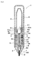
- the cross-sectional view of the writing instrument according to one embodiment of the present invention is as illustrated in Figure 1 .
- the writing instrument 1 is a direct liquid type writing instrument, in which a pen point 2 and an ink tank 4 are attached to both ends of a pen point retaining member 3.
- combs 31 in which an ink effused due to the increase of the internal pressure of the ink tank 4 is temporarily retained are formed.
- Reservation grooves 32 and a guiding groove 33 are defined by the combs 31, so that the function of reserving an ink is exerted.
- the ink tank 4 is attached to a rear end side when the pen point side of the writing instrument 1 is regarded as a leading end side.
- the ink tank 4 is releasably attached without limitation.
- the writing instrument according to the present invention is a writing instrument with an interchangeable ink tank.
- the writing instrument 1 illustrated in Figure 1 further includes a leading shaft 5 and a rear shaft 6.
- the leading shaft 5 accommodates the pen point retaining member 3, and a threaded engagement structure for releasably attaching the rear shaft 6 is disposed in the rear end portion thereof.
- a structure to which the ink tank 4 is releasably attached is disposed in the rear end side of the pen point retaining member accommodated in the leading shaft 5.
- the rear end of the leading shaft 5 described below protrudes to form a cylindrical binding portion 52, to which the ink tank 4 is releasably connected.
- the ink tank 4 is accommodated in the rear shaft 6 by attaching the rear shaft 6.
- the pen point 2 is attached to the leading end of the pen point retaining member 3 via a holder 7.
- An ink is guided from the ink tank 4 to the pen point 2 by an ink guiding member 8 which penetrates the pen point retaining member 3.
- the leading shaft 5 includes a cylindrical structure, of which both ends are opened, for example, a hollow cylinder, and is obtained by injection molding or the like of a synthetic resin (for example, polypropylene, polycarbonate, or the like).
- the rear end portion of the leading shaft 5 is provided with a cylindrical threaded engagement portion 51, of which the diameter is reduced, and the cylindrical binding portion 52 which is concentrically placed on the inside of the threaded engagement portion 51.
- a male screw portion 51a is formed on the outer surface of the threaded engagement portion 51.
- the binding portion 52 is pressed into the opening of the ink tank 4 when the ink tank 4 is attached.
- a projection 52a for backward pushing off a plug body 41 in the opening of the ink tank 4 to open the plug when the ink tank 4 is attached is formed in a part of the rear end of the binding portion 52.
- the rear shaft 6 includes a bottomed cylindrical body, of which the leading end side is opened, and is obtained by injection molding or the like of a synthetic resin (for example, polypropylene, polycarbonate, or the like).
- a female screw portion 61 that can be threadedly engaged releasably with the male screw portion 51a of the threaded engagement portion 51 of the leading shaft 5 is formed on the inner peripheral surface of the leading end side opening of the rear shaft 6.
- the rear shaft 6 preferably has transparency so that the amount of residual ink in the ink tank 4 can be viewed from the outside.
- the pen point retaining member 3 is obtained by injection molding or the like of a synthetic resin (for example, ABS resin or the like).
- the pen point 2 and the ink tank 4 are attached to the pen point retaining member 3.
- the ink tank 4 is releasably attached while the pen point 2 is unreleasably attached.
- the pen point can also be releasably attached to be intended to be used for a longer term.
- the pen point retaining member 3 has the function of linking the ink tank to the pen point.
- the pen point retaining member is preferably provided with an ink reserving function.
- the writing instrument illustrated in Figure 1 includes the pen point retaining member having the ink reserving function.
- the pen point retaining member 3 includes the plural combs 31 which are discoidal.
- the reservation grooves 32 for temporarily reserving an ink are formed mutually between the combs 31.
- the slit-like guiding groove 33 that is connected to each reservation groove 32 and extends in an axial direction is formed on the combs 31.
- a communication groove 35 which is connected to the guiding groove 33 and of which the side closer to the ink tank 4 is opened is installed to penetrate back and forth a collar portion 34 located at the rearmost end of the group of the combs 31 of the pen point retaining member 3 (see Figure 2 ).
- concave grooves 36 for circulating air are formed on the combs 31.
- a central hole 37 is installed to penetrate the center of the pen point retaining member 3.
- a first ink guiding member 81 including an extrusion-molded body of a synthetic resin is attached by being inserted into the central hole 37.
- the member having the ink reserving function of temporarily retaining an ink effused due to the increase of the internal pressure of the ink tank was described as an example of the pen point retaining member, but the pen point retaining member is not particularly limited thereto.
- the ink tank 4 is obtained by injection-molding or the like of a synthetic resin (for example, polyethylene or the like).
- the ink tank 4 is generally a bottomed cylindrical body of which the leading end is opened and the rear end is closed, and in which the inner peripheral surface of the opening is provided with the plug body 41, which blockades the interior of the ink tank 4, by fitting, welding, adhering, or the like.
- An ink for a writing instrument is accommodated directly in the ink tank 4.
- the ink tank 4 preferably has transparency so that the amount of residual ink therein can be viewed.
- the ink tank that is a bottomed cylindrical body is illustrated in Figure 1 , but the ink tank is not limited thereto. In other words, the ink tank may be an ink accommodating tube of which a terminal portion is opened.
- examples of the ink used in the writing instrument according to the present invention include water-based inks, water-based gel inks, oil-based inks, and the like, without particular limitation.
- a water-based ink with Newtonian viscosity and a water-based ink imparted with shear-thinning viscosity are preferred since the contact portion between the ball and the ball holding portion tends to become in boundary lubrication to be prone to be worn, and therefore, the effect of improvement in durability by the present invention is prominently produced.
- the viscosity of the ink used in the present invention is not also particularly limited, but the case of using an ink having a viscosity of less than 10 mPa ⁇ s (20°C) in writing is also preferred since the effect of the present invention is similarly prominently produced.
- the ink used in the writing instrument according to the present invention includes a lubricating interface layer-forming compound.
- the lubricating interface layer-forming compound is a compound having the action of forming a lubricating interface layer between the ball and the inner surface of the ball holding portion.
- This lubricating interface layer is a layer having the action of inhibiting the ball and the ball holding portion from coming into direct contact with each other and from being in boundary lubrication.
- the lubricating interface layer-forming compound is not particularly limited if enabling the formation of a lubricating interface layer between the ball and the ball holding portion as described above, and specific examples thereof include an organic compound having an organic acid group or an organic acid residue.
- carboxyl group or phosphoryl group is preferred, and carboxyl group is particularly preferred.
- the organic acid residues are formed by reaction of the organic acid groups with other metal atoms or organic compounds such as alcohols.
- the lubricating interface layer-forming compound in the present invention may contain two or more groups of, or two or more kinds of the organic acid groups or the organic acid residues.
- an organic group bound to the organic acid group or the organic acid residue can be appropriately selected depending on an ink of interest and is not particularly limited.
- Such an organic group is generally a saturated or unsaturated hydrocarbon group, and for example, a lubricating interface layer-forming compound used in a water-based ink preferably has a substituent that enhancing water solubility because of desirably having high water solubility.
- substituents include hydroxyl group, ether group, carbonyl group, ketone group, amino group, amide group, alkyleneoxy group, acyl group, carboxyl group, ester group, phosphate group, sulfonate group, and the like.
- the organic acid group may also exert the function of enhancing water solubility.
- Such lubricating interface layer-forming compounds include fatty acids, alkylbenzene sulfonic acids, phosphate esters, amino acids, N-acylamino acids, aliphatic amide alkylene oxide adducts, terpenoid acid derivatives, salts thereof, and the like.
- preferred lubricating interface layer-forming compounds include oleic acid, stearic acid, linolic acid, linolenic acid, ricinoleic acid, dodecylbenzenesulfonic acid, polyoxyethylene alkyl ether phosphate ester, polyoxyethylene alkyl phenyl ether phosphate ester, alanine, glycine, lysine, threonine, serine, proline, sarcosine, N-acylsarcosine, polyoxyethylene fatty acid amide, salts thereof, and the like. These may also be used in combination of two or more kinds.
- the lubricating interface layer-forming compound is considered to have the action of enhancing an affinity between the ink and the carbonaceous film.
- an ink used in a conventional ball-point pen containing water and a component having a hydrophilic functional group, such as alcohol or glycol ether.
- the ink containing such a component has had a low affinity for a conventionally used ball, for example, a ball comprising silicon carbide, not subjected to surface treatment, and a contact portion between a ball and a ball holding portion has tended to be prone to be in boundary lubrication.
- the carbonaceous film having a carbon-oxygen bond is formed on either ball or ball holding portion, and it is easy to offer fluid lubrication between the ball and the ball holding portion by using an ink having a high affinity therefor. Therefore, the ink containing the lubricating interface layer-forming compound having a high affinity for the carbonaceous film having a carbon-oxygen bond is used to form the lubricating interface layer between the ball and the ball holding portion and to make it possible to enhance the effect of inhibiting the wear of the ball and the like.
- the reason why the lubricating interface layer is formed in such a manner is considered to be that when an uncombined hand of carbon exists on the surface of the carbonaceous film, the uncombined hand and the lubricating interface layer-forming compound are bound by a reaction such as chemical adsorption by the rotation of the ball, and the surface of the carbonaceous film is coated with the lubricating interface layer-forming compound to form a layer.
- the ink for a writing instrument is a water-based ink for a ball-point pen
- the ink preferably has a pH of 7 to 13, more preferably a pH of 7 to 9.
- the ink is allowed to be alkaline or weak alkaline in such a manner, to obtain the dissolution stability of the lubricating interface layer-forming compound in the water-based ink for a ball-point pen and to further improve the temporal stability of the lubricating interface layer due to the adsorption of the functional group of the lubricating interface layer-forming compound on the surface of the carbonaceous film.
- a part that is not coated with the carbonaceous film is exposed.
- a metal component contained in the ball or the ball holding portion for example, a metallic binding material used in the ball may be eluted with time.
- the eluted metal component is oxidized, becomes insoluble in the ink, and may adhere to the ball surface and the like.
- the elution and the adhesion may result in a defect such as the deterioration of surface smoothness, the inhibition of the rotation of the ball, and the heavier feeling of writing; the inhibition of the smooth outflow of the ink and patchy handwriting; or the like.
- a pH adjuster such as a basic compound represented by an amine can be added particularly when a water-based ink for a ball-point pen is used.
- the adsorption of the lubricating interface layer-forming compound, which is generally acidic, to the surface of the carbonaceous film tends to be inhibited; however, since the deterioration of writing performance due to the elution of a metal component after a lapse of time can be suppressed, the temporal stability of the writing instrument may be able to be comprehensively improved.
- the pen point 2 has a structure in which a ball 24 is rotatably held in the ball holding portion disposed in the leading end.
- a structure is also referred to as a ball-point pen tip.
- the ball 24 is rotatably held by an inward leading edge 22 formed by radially inwardly press-deforming the taper-like leading end portion of a metallic pipe 21 (for example, a pipe comprising stainless steel, copper, aluminum, nickel, or the like), and by a plurality of (for example, three or four) inwardly projecting portions 23 formed by radially inwardly press-deforming a side wall in the vicinity of the leading end of the pipe.
- the plural inwardly projecting portions 23 are placed generally at an equal spacing circumferentially on the inner surface of the pipe 2.
- the ball is held by the extremely leading end portion 22 and the inwardly projecting portions 23 so as not to be removed from the pen point.
- the swaging angle of the leading edge 22 is generally allowed to be from 50° to 100° in consideration of an angle with respect to paper and an ink flow path.
- a cutting-type ball-point pen tip formed by cutting and processing a stainless steel wire rod with a drill is also acceptable.
- the material of the ball 24 include sintered bodies of tungsten carbide, ceramics of zirconia, alumina, silica, silicon carbide, and the like, stainless steel described as examples, or the like.
- a material comprising a metal or a ceramic is generally used. Since durability is demanded in the writing instrument according to the present invention, it is preferable to select a material having a high hardness.
- a ceramic such as tungsten carbide, zirconium oxide, aluminum oxide, silicon oxide, or silicon carbide, or a metal such as stainless steel is used.
- a cemented carbide alloy comprising a ceramic and a metallic binding material may also be used.
- an alloy comprising tungsten carbide and a metallic binding material such as cobalt or nickel is known.
- the ball of tungsten carbide (equivalent to ISO K-10) having a diameter of 0.5 mm is used.
- the size of the ball is determined by the application of the writing instrument, the width of a drawn line demanded in writing, or the like, and is generally selected from the range of 0.25 to 2.0 mm.
- a more preferred effect can be exerted when the ball having a small diameter, for example, the small-diameter ball having a diameter of 0.5 mm or less is used. This is because in the case of writing of the same distance, the lower diameter of the ball results in the more rotation number of the ball and therefore in a tendency to more easily wear the ball holding portion.
- the clearance between the ball and the inner surface of the ball holding portion in the pen point greatly influences a writing property. Therefore, it is preferable to suitably adjust the clearance.
- the suitable clearance varies according to the viscosity of an ink for a writing instrument used, or the like. For example, in a case in which the ink for a writing instrument has a viscosity of less than 10 mPa ⁇ s, a sufficient consumption of ink is not obtained and there is the fear of patchy writing or the like when the clearance at a writing distance of 0 m (no use of the writing instrument) is too narrow, while there is the fear of dripping of the ink when the clearance is too wide. Therefore, the clearance is preferably 5 ⁇ m or more and 25 ⁇ m or less, more preferably 10 ⁇ m or more and 20 ⁇ m or less, most preferably 15 ⁇ m or more and 18 ⁇ m or less.
- a carbonaceous film is formed on at least one of the surface of the ball or the contact portion of the ball holding portion with the ball.
- the carbonaceous film may be formed on both of the surface of the ball and the contact portion.
- FIG 3 an example in which a carbonaceous film 24C is formed on the surface of a ball body 24A via an intermediate layer 24B (detailed below) is illustrated.
- a material including the ball body 24A as well as the intermediate layer 24B and the carbonaceous film 24C may be referred to as the ball 24.
- the carbonaceous film When the carbonaceous film is formed on the ball holding portion, the carbonaceous film may be formed only on a part coming into contact with the ball, while the carbonaceous film may also be formed in a wider range than the actual contact part from the viewpoint of the easiness of production, deformation due to use, and the like. Furthermore, the carbonaceous film may be formed on the whole inner surfaces of the ball holding portion.
- the carbonaceous film has a carbon atom and an oxygen atom bound to the carbon atom. Therefore, the durability of the ball or the ball holding portion is increased.
- the carbonaceous film in the present invention has a high affinity for an ink, the ink is held in a gap between the ball and the interior of the ball holding portion, and direct contact between the ball and the ball holding portion is inhibited. As a result, the wearing of the ball and the interior of the ball holding portion due to the direct contact between the ball and the ball holding portion can be reduced, and the durability is further improved.
- a value of CO total is preferably 0.1 or more and more preferably 0.15 or more since the affinity between the carbonaceous film and the ink is increased, and it is easy to maintain stable writing performance for a long term and over a long distance.
- the value is preferably 0.5 or less and more preferably 0.45 or less.
- the carbonaceous film can be formed on the ball surface or the contact portion of the ball holding portion with the ball by an optional method.
- the carbonaceous film may be formed on either or both of the ball surface or the ball holding portion.
- a method of forming the carbonaceous film is not particularly limited.
- the formation can be performed by a plasma chemical vapor phase deposition method (plasma CVD method), a catalytic chemical vapor phase deposition method (CAT-CVD method), or the like using hydrocarbon gas as a raw material.
- the formation can also be performed by a sputtering method, an arc ion plating method, or the like with solid graphite as a raw material.
- the formation may be performed by another method or by a combination of a plurality of methods.
- the carbonaceous film used in the present invention is a film containing an sp 2 carbon-carbon bond (graphite bond) and an sp 3 carbon-carbon bond (diamond bond), which film is represented by a diamond like film (DLC film).
- a higher proportion of an sp 3 carbon-carbon bond to an sp 2 carbon-carbon bond is preferred since the hardness of the carbonaceous film is higher.
- the proportion of the sp 3 carbon-carbon bond to the sp 2 carbon-carbon bond is preferably 0.3 or more.
- the carbonaceous film typically contains an sp 2 carbon-hydrogen bond and an sp 3 carbon-hydrogen bond
- a carbon-hydrogen bond is not an essential component in the carbonaceous film in the present invention.
- silicon (Si), fluorine (F), or the like may also be added in a range in which the effect of the present invention is not deteriorated.
- a method of introducing a carbon-oxygen bond into the carbonaceous film may be performed by irradiation with, for example, oxygen plasma, plasma of a gas containing oxygen, or the like.
- oxygen can also be introduced by irradiating the carbonaceous film with ultraviolet rays in an atmosphere containing oxygen or by immersing the carbonaceous film in an oxidative solution.
- a carbon-oxygen bond can also be introduced by increasing the concentration of oxygen in an atmosphere when the carbonaceous film is formed.
- an uncombined hand exists on the surface thereof. Therefore, the uncombined hand can also be allowed to react with oxygen to introduce a carbon-oxygen bond by leaving the carbonaceous film, just after having been formed, standing in an atmosphere containing oxygen.
- a carbon atom with an uncombined hand may also exist if a carbon-oxygen bond is introduced.
- the film thickness of the carbonaceous film is not particularly limited but preferably ranges from 0.001 ⁇ m to 3 ⁇ m, more preferably ranges from 0.005 ⁇ m to 1 ⁇ m. Further, the carbonaceous film can be formed directly on the surface of the ball or the ball holding portion; however, in order to allow the ball or the ball holding portion and the carbonaceous film to more firmly adhere to each other, it is preferable to dispose an intermediate layer.
- the material of the intermediate layer various materials can be used depending on the kind of the ball or the ball holding portion, and, for example, a known material such as an amorphous film comprising silicon (Si) and carbon (C), titanium (Ti) and carbon (C), or chromium (Cr) and carbon (C) can be used.
- the thickness thereof is not particularly limited but preferably ranges from 0.001 ⁇ m to 0.3 ⁇ m and more preferably ranges from 0.005 ⁇ m to 0.1 ⁇ m.
- the intermediate layer can be formed by using, for example, a sputtering method, a CVD method, a plasma CVD method, a spraying method, an ion plating method, an arc ion plating method, or the like.
- the pen point 2 is attached to the front of the holder 7.
- the rear of the holder 7 is pressed into the leading end opening of the central hole 37 of the ink retaining member 3.
- the pen point 2 is attached to the ink retaining member 3 via the holder 7.
- the holder 7 includes a collar-like front, to which the pen point 2 is attached, and a rear pressed into the leading end opening of the central hole 37 of the ink retaining member 3.
- the holder 7 is obtained by injection-molding or the like of a synthetic resin or the like.
- the ink guiding member 8 includes the first ink guiding member 81, a second ink guiding member 82, and a third ink guiding member 83.
- the second ink guiding member 82 including a fiber-processed body is accommodated in the rear of the holder 7.
- the third ink guiding member 83 which guides ink to the rear face of the ball 24 and includes an extrusion-molded body of a synthetic resin is accommodated in the pen point 2.
- the rear end of the third ink guiding member 83 intrudes into and is connected to the leading end of the second ink guiding member 82, while the leading end of the first ink guiding member 81 intrudes into and is connected to the rear end of the second ink guiding member 82.
- the third ink guiding member 83 is allowed to abut on the inner surface (rear inner surface) of each inwardly projecting portion 23.
- the carbonaceous film is formed on at least one of the ball or the ball holding portion.
- a method of forming a carbonaceous film will be explained below. As an example, a method of forming a carbonaceous film on a ball surface will be explained. A similar method can also be applied to the case of forming a carbonaceous film on a ball holding portion.
- an intermediate layer Prior to the formation of the carbonaceous film on the ball surface, an intermediate layer can be formed.
- an ionic vapor deposition method can be used for the film formation of the intermediate layer.
- the interior of a chamber for ionized deposition is adjusted to predetermined pressure using a vacuum pump, tetramethylsilane (Si(CH 3 ) 4 ) is introduced into the chamber, and a bias voltage (for example, 1 kV) is applied to the ball to cause discharge (for, e.g., 30 minutes).
- the intermediate layer can be formed on the whole surface of the ball by rotating the ball in the chamber when the film is formed.
- the gas supplied into the chamber is switched to benzene to form the carbonaceous film.
- the interior of the chamber is adjusted to predetermined pressure using a vacuum pump, and a bias voltage (for example, 1 kV) is thereafter applied to the ball to cause discharge (for, e.g., 90 minutes).
- a bias voltage for example, 1 kV
- the carbonaceous film can be formed on the whole surface of the ball by rotating the ball in the chamber when the film is formed.
- plasma irradiation is optionally performed in an atmosphere containing oxygen to introduce a carbon-oxygen bond into the carbonaceous film.
- Plasma irradiation is performed at a pressure adjusted to, for example, 100 Pa in the chamber and at an output of, for example, 10 W, whereby the ball of interest can be obtained.
- the rate of the carbon-oxygen bond contained in the obtained carbonaceous film can be evaluated by X-ray photoelectron spectroscopy (XPS) measurement. Measurement conditions are adjusted depending on the kind, thickness, and the like of a carbonaceous film to be formed, for example, a detection angle with respect to a sample can be 90°, Al can be used as an X-ray source, and X-ray irradiation energy can be 100 W. Time of one measurement is generally around 0.1 ms. Further, in order to enhance measurement accuracy, measurement of one sample may be performed several times, for example, 64 times to regard the average value thereof as a measurement result.
- XPS X-ray photoelectron spectroscopy
- a value obtained by dividing the area of each peak obtained by the curve fitting by the overall area of the C1s peak is regarded as the composition ratio of each component.
- the thicknesses of the intermediate layer and the carbonaceous film can be measured by analyzing the ball, on which the carbonaceous film is formed, with an Auger electron spectroscopy device (PHI-660 Type (trade name), manufactured by ULVAC-PHI, Inc.). Specifically, the surface of the ball on which the carbonaceous film is formed is etched in stages, and the surface is analyzed at each stage by an Auger electron spectroscopy analysis method. As measurement conditions, for example, the acceleration voltage of an electron gun is set at 10 kV, a sample current is set at 500 nm, and the acceleration voltage of an argon ion gun is set at 2 kV. A region measuring 40 ⁇ m per side on the ball surface is analyzed at each depth under the measurement conditions, whereby the thicknesses of the intermediate layer and the carbonaceous film can be measured.
- PHI-660 Type trade name
- a ball (DLC-1) on the ball surface of which a carbonaceous film was formed and a ball (DLC-2) in which a carbonaceous film in which the rate of carbon-oxygen bond was varied by changing plasma irradiation conditions was obtained were produced by the method. Specifically, DLC-1 was irradiated with oxygen plasma for 60 seconds at an output of 10 W from a high frequency power source. DLC-2 was irradiated with oxygen plasma for 60 seconds at an output of 50 W from the high frequency power source. The rate of each bond contained in the carbonaceous films formed on the balls was measured by the method. The obtained results are as listed in Table 1.
- the proportions (CO total ) of carbon atoms bound to oxygen atoms with respect to the total carbon atoms in DLC-1 and DLC-2 were 0.16 and 0.43, respectively.
- the value of CO total in DLC-2 with the higher power output in the irradiation with oxygen plasma was higher than that in DLC-1.
- a contact angle between the surface of each ball of a tungsten carbide ball (WC) on which no carbonaceous film was formed, DLC-1 described above, or DLC-2 described above, and an ink for a writing instrument was measured.
- the measurement was performed using, as an ink for a writing instrument, a blue ink comprising 5.0 mass% of a blue dye (WATER BLUE 105S (trade name), manufactured by ORIENT CHEMICAL INDUSTRIES CO., LTD.), 0.5 mass% of a lubricating interface layer-forming compound (phosphate ester (PLYSURF AL (trade name), manufactured by DKS Co.Ltd.)), 1.0 mass% of triethanolamine, 5.0 mass% of diethylene glycol, 3.0 mass% of 2-pyrrolidone, and 85.5 mass% of water.
- a blue ink comprising 5.0 mass% of a blue dye (WATER BLUE 105S (trade name), manufactured by ORIENT CHEMICAL INDUSTRIES CO., LTD.
- the viscosity of the ink was measured using a B type viscometer ((BL ADAPTOR) manufactured by TOKYO KEIKI INC.), the viscosity of the ink was 2 mPa ⁇ s under an environment of 20°C. In addition, the pH thereof was 9.0.
- the contact angle of DLC-1 is less, the contact angle of DLC-2 is further less, and the affinities thereof are high. It is clear that an affinity for an ink for a writing instrument is improved by forming a carbonaceous film having a carbon-oxygen bond.
- DM-500 (trade name) manufactured by Kyowa Interface Science Co., Ltd.
- WC test plate
- ISO K-10 carbonaceous film disposed under the same conditions as those of the carbonaceous film disposed on the ball
- the contact angle can be determined by measurement performed 3 seconds after the dropwise addition (measured value was an average value at three points).
- the surface tension of the water-based ink was 40 mN/m.
- the surface tension of an ink is preferably 20 mN/m or more and 40 mN/m or less, most preferably 25 mN/m to 35 mN/m, under an environment at 20°C so that the ink is smoothly supplied when an ink tank is exchanged.
- the surface tension can be determined by measurement by a vertical plate method using a glass plate, under an environment at 20°C, using a surface tension measuring instrument manufactured by Kyowa Interface Science Co., Ltd.
- a writing implement including each ball described above was prepared to conduct a running test.
- the test is a test in which a writing instrument is retained in the state of being tilted at 70° with respect to a paper surface and is rotated to draw a circle having a diameter of 32 mm at a load of 100 gf (about 0.98 N), and a writing distance by the writing instrument is investigated using a tester that moves writing paper (JIS: P3201) at a speed of 4 m/min. Writing of a distance of about 10 cm is achieved by drawing one circle by the writing instrument. A distance from the leading end of a pen point to the leading end position of the ball was measured every 100 m of the writing distance.
- the change amount (depression amount) of the leading end position of the ball was regarded as a wear amount. Further, after the exhaustion of the ink filled in the ink tank, the ink tank was exchanged, and the running test was further continued.
- the specific change amount (depression amount) of the leading end position of the ball in DLC-1 was 0 ⁇ m in non-writing, 3 ⁇ m after 0-100 m writing, 4 ⁇ m after 500 m writing, or 4 ⁇ m after 1000 m writing.
- the amount was 5 ⁇ m after 1500 m writing, 5 ⁇ m after 2000 m writing, 6 ⁇ m after 3000 m writing, or 6 ⁇ m after 5000 m writing.
- uniform handwriting is inhibited when the change amount (depression amount) of the leading end position of the ball is more than 10 ⁇ m.
- a water-based ink (pH 9.0) comprising 40.0 mass% of a water soluble dye (WATER BLACK 191L (trade name), manufactured by ORIENT CHEMICAL INDUSTRIES CO., LTD.), 1.0 mass% of sarcosine (lubricating interface layer-forming compound), 1.0 mass% of triethanolamine (pH adjuster), 5.0 mass% of ethylene glycol, and 53.0 mass% of water
- WATER BLACK 191L trade name
- sarcosine lubricating interface layer-forming compound
- triethanolamine pH adjuster
- an oil-based ink comprising 20.0 mass% of a dye (SPILON BLACK GMH-SPECIAL (trade name), manufactured by Hodogaya Chemical Co., Ltd.), 18.0 mass% of a dye (VALIFAST VIOLET 1701 (trade name), manufactured by ORIENT CHEMICAL INDUSTRIES CO., LTD.), 23.0 mass% of benzyl alcohol, 32.0 mass% of ethylene glycol monophenyl ether, 2.0 mass% of oleic acid (lubricating interface layer-forming compound), 2.0 mass% of NYMEEN L-201 (trade name, manufactured by NOF CORPORATION), 0.5 mass% of polyvinyl pyrrolidone (agent for imparting stringiness), and 2.5 mass% of a viscosity modifier (HILACK 110H (trade name), manufactured by Hitachi Chemical Company, Ltd.), to measure a wear amount
Landscapes
- Chemical & Material Sciences (AREA)
- Engineering & Computer Science (AREA)
- Materials Engineering (AREA)
- Organic Chemistry (AREA)
- Mechanical Engineering (AREA)
- Metallurgy (AREA)
- General Chemical & Material Sciences (AREA)
- Chemical Kinetics & Catalysis (AREA)
- Inorganic Chemistry (AREA)
- Life Sciences & Earth Sciences (AREA)
- Wood Science & Technology (AREA)
- Pens And Brushes (AREA)
Abstract
Description
- The present invention relates to writing instruments. Specifically, the present invention relates to a writing instrument including a pen point retaining member, a pen point that is attached to a first end of the pen point retaining member, an ink tank that is attached to a second end of the pen point retaining member, and an ink that is accommodated in the ink tank.
- There has been conventionally known a ball-point pen, in which an ink tank in which an ink for a ball-point pen is accommodated is disposed in a shaft cylinder, and a ball is put on the bottom wall of a ball holding portion, and which includes a pen point of which the leading end portion is inwardly crimped, whereby a part of the ball is allowed to protrude from the leading edge of the pen point, and the ball is rotatably held.
- A ball-point pen performs writing by transferring ink, flowing out of an ink tank, onto a body to be recorded, such as paper, or by allowing the ink to infiltrate into the body to be recorded, due to rotation of a ball. The wear of the ball and the inner surface of a ball holding portion prevents the ball from smoothly rotating, results in great deterioration of writing characteristics, and finally precludes writing. Therefore, the reduction of the wear of the ball and the ball holding portion is an important problem.
- Use of a ceramic ball, coating of the surface of a metallic ball with a rigid material such as a diamond-like carbon film for reducing the wear of the ball and the ball holding portion (for example, Patent Literature 1), and the like have been attempted with respect to such problems. Coating of the surface of not only the ball but also the ball holding portion with a rigid material for reducing the wear of the ball holding portion by the ball has been also attempted.
- Patent Literature 1: Japanese Patent Laid-Open No.
2004-338134 - However, even when only the hardness of a ball or a ball holding portion is increased as in Patent Literature 1, it is difficult to prevent the ball and the ball holding portion from being worn to realize sufficient durability. This is because when the contact site between the ball and the ball holding portion is microscopically observed, the contact site may be in the state of boundary lubrication in which the ball and the ball holding portion come into direct contact with each other without the existence of an ink for a writing instrument in the interface between the ball and the ball holding portion. Such a phenomenon has tended to be prone to occur particularly when an ink having low viscosity has been used.
- A state in which an appropriate amount of ink is present on the interface between the ball and the ball holding portion, and the ball and the ball holding portion do not come into direct contact with each other is important for reducing such wear of the ball and the ball holding portion.
- The writing instrument according to the present invention is a writing instrument including:
- a pen point retaining member;
- a pen point that includes a ball and a ball holding portion that rotatably holds the ball, and is attached to a first end of the pen point retaining member;
- an ink tank that is attached to a second end of the pen point retaining member; and
- an ink for a writing instrument that is accommodated in the ink tank and includes a lubricating interface layer-forming compound,
wherein a carbonaceous film is formed on at least one of a surface of the ball or a contact portion of the ball holding portion with the ball; and the carbonaceous film includes a carbon atom and an oxygen atom bound to the carbon atom. - The present invention is to provide a ball-point pen in which favorable writing can be obtained over a long distance and a long term.
-
- [
Figure 1] Figure 1 is a longitudinal cross-sectional view of a writing instrument according to an embodiment of the present invention. - [
Figure 2] Figure 2 is a cross-sectional view of the line A-A ofFigure 1 . - [
Figure 3] Figure 3 is an enlarged vertical longitudinal sectional view of the principal portion ofFigure 1 . - An embodiment of the writing instrument according to the present invention will be explained in detail below with reference to the drawings.
- The cross-sectional view of the writing instrument according to one embodiment of the present invention is as illustrated in
Figure 1 . The writing instrument 1 is a direct liquid type writing instrument, in which apen point 2 and anink tank 4 are attached to both ends of a penpoint retaining member 3. On the penpoint retaining member 3,combs 31 in which an ink effused due to the increase of the internal pressure of theink tank 4 is temporarily retained are formed.Reservation grooves 32 and a guidinggroove 33 are defined by thecombs 31, so that the function of reserving an ink is exerted. Theink tank 4 is attached to a rear end side when the pen point side of the writing instrument 1 is regarded as a leading end side. InFigure 1 , theink tank 4 is releasably attached without limitation. However, in the present invention, since the durability of a pen point portion is very high, the pen point portion can be used for a long term, and it is preferable that ink can be refilled. Therefore, the writing instrument according to the present invention is a writing instrument with an interchangeable ink tank. - The writing instrument 1 illustrated in
Figure 1 further includes a leadingshaft 5 and arear shaft 6. The leadingshaft 5 accommodates the penpoint retaining member 3, and a threaded engagement structure for releasably attaching therear shaft 6 is disposed in the rear end portion thereof. A structure to which theink tank 4 is releasably attached is disposed in the rear end side of the pen point retaining member accommodated in the leadingshaft 5. In the writing instrument illustrated inFigure 1 , the rear end of the leadingshaft 5 described below protrudes to form a cylindrical bindingportion 52, to which theink tank 4 is releasably connected. Theink tank 4 is accommodated in therear shaft 6 by attaching therear shaft 6. Thepen point 2 is attached to the leading end of the penpoint retaining member 3 via aholder 7. An ink is guided from theink tank 4 to thepen point 2 by anink guiding member 8 which penetrates the penpoint retaining member 3. - The leading
shaft 5 includes a cylindrical structure, of which both ends are opened, for example, a hollow cylinder, and is obtained by injection molding or the like of a synthetic resin (for example, polypropylene, polycarbonate, or the like). The rear end portion of the leadingshaft 5 is provided with a cylindrical threadedengagement portion 51, of which the diameter is reduced, and thecylindrical binding portion 52 which is concentrically placed on the inside of the threadedengagement portion 51. Amale screw portion 51a is formed on the outer surface of the threadedengagement portion 51. Thebinding portion 52 is pressed into the opening of theink tank 4 when theink tank 4 is attached. Furthermore, aprojection 52a for backward pushing off aplug body 41 in the opening of theink tank 4 to open the plug when theink tank 4 is attached is formed in a part of the rear end of thebinding portion 52. - The
rear shaft 6 includes a bottomed cylindrical body, of which the leading end side is opened, and is obtained by injection molding or the like of a synthetic resin (for example, polypropylene, polycarbonate, or the like). Afemale screw portion 61 that can be threadedly engaged releasably with themale screw portion 51a of the threadedengagement portion 51 of the leadingshaft 5 is formed on the inner peripheral surface of the leading end side opening of therear shaft 6. Further, therear shaft 6 preferably has transparency so that the amount of residual ink in theink tank 4 can be viewed from the outside. - The pen
point retaining member 3 is obtained by injection molding or the like of a synthetic resin (for example, ABS resin or the like). Thepen point 2 and theink tank 4 are attached to the penpoint retaining member 3. InFigure 1 , theink tank 4 is releasably attached while thepen point 2 is unreleasably attached. In other words, in the present invention, since the wear of the pen point is reduced by the combination of the specific pen point and the specific ink, there is no need for exchanging the pen point, and therefore, it is not necessary to allow the pen point to be releasable. However, the pen point can also be releasably attached to be intended to be used for a longer term. - In the present invention, the pen
point retaining member 3 has the function of linking the ink tank to the pen point. In order to realize a higher writing property, the pen point retaining member is preferably provided with an ink reserving function. The writing instrument illustrated inFigure 1 includes the pen point retaining member having the ink reserving function. - The pen
point retaining member 3 includes the plural combs 31 which are discoidal. Thereservation grooves 32 for temporarily reserving an ink are formed mutually between thecombs 31. The slit-like guiding groove 33 that is connected to eachreservation groove 32 and extends in an axial direction is formed on thecombs 31. Acommunication groove 35 which is connected to the guidinggroove 33 and of which the side closer to theink tank 4 is opened is installed to penetrate back and forth acollar portion 34 located at the rearmost end of the group of thecombs 31 of the pen point retaining member 3 (seeFigure 2 ). Further,concave grooves 36 for circulating air are formed on thecombs 31. Further, acentral hole 37 is installed to penetrate the center of the penpoint retaining member 3. A firstink guiding member 81 including an extrusion-molded body of a synthetic resin is attached by being inserted into thecentral hole 37. - The member having the ink reserving function of temporarily retaining an ink effused due to the increase of the internal pressure of the ink tank was described as an example of the pen point retaining member, but the pen point retaining member is not particularly limited thereto.
- In the writing instrument illustrated in
Figure 1 , theink tank 4 is obtained by injection-molding or the like of a synthetic resin (for example, polyethylene or the like). Theink tank 4 is generally a bottomed cylindrical body of which the leading end is opened and the rear end is closed, and in which the inner peripheral surface of the opening is provided with theplug body 41, which blockades the interior of theink tank 4, by fitting, welding, adhering, or the like. An ink for a writing instrument is accommodated directly in theink tank 4. Theink tank 4 preferably has transparency so that the amount of residual ink therein can be viewed. The ink tank that is a bottomed cylindrical body is illustrated inFigure 1 , but the ink tank is not limited thereto. In other words, the ink tank may be an ink accommodating tube of which a terminal portion is opened. - Although the direct liquid type writing instrument in which ink is accommodated directly in the ink tank is described as an example in
Figure 1 , an inner cotton type writing instrument in which inner cotton is impregnated with ink is also acceptable. - Further, examples of the ink used in the writing instrument according to the present invention include water-based inks, water-based gel inks, oil-based inks, and the like, without particular limitation. However, a water-based ink with Newtonian viscosity and a water-based ink imparted with shear-thinning viscosity are preferred since the contact portion between the ball and the ball holding portion tends to become in boundary lubrication to be prone to be worn, and therefore, the effect of improvement in durability by the present invention is prominently produced. Furthermore, the viscosity of the ink used in the present invention is not also particularly limited, but the case of using an ink having a viscosity of less than 10 mPa·s (20°C) in writing is also preferred since the effect of the present invention is similarly prominently produced.
- Further, the ink used in the writing instrument according to the present invention includes a lubricating interface layer-forming compound. As used herein, the lubricating interface layer-forming compound is a compound having the action of forming a lubricating interface layer between the ball and the inner surface of the ball holding portion. This lubricating interface layer is a layer having the action of inhibiting the ball and the ball holding portion from coming into direct contact with each other and from being in boundary lubrication.
- The lubricating interface layer-forming compound is not particularly limited if enabling the formation of a lubricating interface layer between the ball and the ball holding portion as described above, and specific examples thereof include an organic compound having an organic acid group or an organic acid residue.
- In the present invention, the organic acid group is an organic acidic group such as, for example, carboxyl group (-COOH), phosphoryl group (-P(=O)(OH)2), sulfo group (-SO3H), sulfino group (-SO2H), or hydroxyphenyl group (-C6H4OH). Of these, carboxyl group or phosphoryl group is preferred, and carboxyl group is particularly preferred. These groups exert superior wear prevention effects, and this is considered to be because these groups have particularly high affinities for a carbonaceous film (detailed below). Further, the organic acid residues are groups obtained by removing hydrogen from the organic acid groups, such as, for example, -COO-, -P(=O)(OH)O-, -P(=O)(O-)2, -SO3-, -SO2-, and -C6H4O-. The organic acid residues are formed by reaction of the organic acid groups with other metal atoms or organic compounds such as alcohols. The lubricating interface layer-forming compound in the present invention may contain two or more groups of, or two or more kinds of the organic acid groups or the organic acid residues.
- Further, an organic group bound to the organic acid group or the organic acid residue can be appropriately selected depending on an ink of interest and is not particularly limited. Such an organic group is generally a saturated or unsaturated hydrocarbon group, and for example, a lubricating interface layer-forming compound used in a water-based ink preferably has a substituent that enhancing water solubility because of desirably having high water solubility. Such substituents include hydroxyl group, ether group, carbonyl group, ketone group, amino group, amide group, alkyleneoxy group, acyl group, carboxyl group, ester group, phosphate group, sulfonate group, and the like. In other words, the organic acid group may also exert the function of enhancing water solubility.
- Such lubricating interface layer-forming compounds include fatty acids, alkylbenzene sulfonic acids, phosphate esters, amino acids, N-acylamino acids, aliphatic amide alkylene oxide adducts, terpenoid acid derivatives, salts thereof, and the like. More specifically, preferred lubricating interface layer-forming compounds include oleic acid, stearic acid, linolic acid, linolenic acid, ricinoleic acid, dodecylbenzenesulfonic acid, polyoxyethylene alkyl ether phosphate ester, polyoxyethylene alkyl phenyl ether phosphate ester, alanine, glycine, lysine, threonine, serine, proline, sarcosine, N-acylsarcosine, polyoxyethylene fatty acid amide, salts thereof, and the like. These may also be used in combination of two or more kinds.
- In the present invention, the lubricating interface layer-forming compound is considered to have the action of enhancing an affinity between the ink and the carbonaceous film. For example, there has been an ink used in a conventional ball-point pen, containing water and a component having a hydrophilic functional group, such as alcohol or glycol ether. The ink containing such a component has had a low affinity for a conventionally used ball, for example, a ball comprising silicon carbide, not subjected to surface treatment, and a contact portion between a ball and a ball holding portion has tended to be prone to be in boundary lubrication. However, in the present invention, the carbonaceous film having a carbon-oxygen bond is formed on either ball or ball holding portion, and it is easy to offer fluid lubrication between the ball and the ball holding portion by using an ink having a high affinity therefor. Therefore, the ink containing the lubricating interface layer-forming compound having a high affinity for the carbonaceous film having a carbon-oxygen bond is used to form the lubricating interface layer between the ball and the ball holding portion and to make it possible to enhance the effect of inhibiting the wear of the ball and the like. The reason why the lubricating interface layer is formed in such a manner is considered to be that when an uncombined hand of carbon exists on the surface of the carbonaceous film, the uncombined hand and the lubricating interface layer-forming compound are bound by a reaction such as chemical adsorption by the rotation of the ball, and the surface of the carbonaceous film is coated with the lubricating interface layer-forming compound to form a layer.
- When the ink for a writing instrument is a water-based ink for a ball-point pen, the ink preferably has a pH of 7 to 13, more preferably a pH of 7 to 9. The ink is allowed to be alkaline or weak alkaline in such a manner, to obtain the dissolution stability of the lubricating interface layer-forming compound in the water-based ink for a ball-point pen and to further improve the temporal stability of the lubricating interface layer due to the adsorption of the functional group of the lubricating interface layer-forming compound on the surface of the carbonaceous film.
- When the carbonaceous film is formed only on either ball or ball holding portion, a part that is not coated with the carbonaceous film is exposed. When the ink comes into contact with the exposed part, a metal component contained in the ball or the ball holding portion, for example, a metallic binding material used in the ball may be eluted with time. The eluted metal component is oxidized, becomes insoluble in the ink, and may adhere to the ball surface and the like. The elution and the adhesion may result in a defect such as the deterioration of surface smoothness, the inhibition of the rotation of the ball, and the heavier feeling of writing; the inhibition of the smooth outflow of the ink and patchy handwriting; or the like. In view of such facts, in consideration of the temporal stability of a ball-point pen, a pH adjuster such as a basic compound represented by an amine can be added particularly when a water-based ink for a ball-point pen is used. In this case, the adsorption of the lubricating interface layer-forming compound, which is generally acidic, to the surface of the carbonaceous film tends to be inhibited; however, since the deterioration of writing performance due to the elution of a metal component after a lapse of time can be suppressed, the temporal stability of the writing instrument may be able to be comprehensively improved.
- The
pen point 2 has a structure in which aball 24 is rotatably held in the ball holding portion disposed in the leading end. Such a structure is also referred to as a ball-point pen tip. In the ball holding portion, theball 24 is rotatably held by an inwardleading edge 22 formed by radially inwardly press-deforming the taper-like leading end portion of a metallic pipe 21 (for example, a pipe comprising stainless steel, copper, aluminum, nickel, or the like), and by a plurality of (for example, three or four) inwardly projectingportions 23 formed by radially inwardly press-deforming a side wall in the vicinity of the leading end of the pipe. The plural inwardly projectingportions 23 are placed generally at an equal spacing circumferentially on the inner surface of thepipe 2. The ball is held by the extremelyleading end portion 22 and the inwardly projectingportions 23 so as not to be removed from the pen point. The swaging angle of the leadingedge 22 is generally allowed to be from 50° to 100° in consideration of an angle with respect to paper and an ink flow path. - Although the pipe-type ball-point pen tip formed by press-processing or the like of a pipe made of stainless steel is illustrated as an example in
Figure 1 , a cutting-type ball-point pen tip formed by cutting and processing a stainless steel wire rod with a drill is also acceptable. Examples of the material of theball 24 include sintered bodies of tungsten carbide, ceramics of zirconia, alumina, silica, silicon carbide, and the like, stainless steel described as examples, or the like. - As the material of the ball held by the pen point, which is not particularly limited, a material comprising a metal or a ceramic is generally used. Since durability is demanded in the writing instrument according to the present invention, it is preferable to select a material having a high hardness. For example, a ceramic such as tungsten carbide, zirconium oxide, aluminum oxide, silicon oxide, or silicon carbide, or a metal such as stainless steel is used. A cemented carbide alloy comprising a ceramic and a metallic binding material may also be used. As such a cemented carbide alloy, an alloy comprising tungsten carbide and a metallic binding material such as cobalt or nickel is known.
- In the writing instrument illustrated in
Figure 1 , the ball of tungsten carbide (equivalent to ISO K-10) having a diameter of 0.5 mm is used. The size of the ball is determined by the application of the writing instrument, the width of a drawn line demanded in writing, or the like, and is generally selected from the range of 0.25 to 2.0 mm. In the present invention, a more preferred effect can be exerted when the ball having a small diameter, for example, the small-diameter ball having a diameter of 0.5 mm or less is used. This is because in the case of writing of the same distance, the lower diameter of the ball results in the more rotation number of the ball and therefore in a tendency to more easily wear the ball holding portion. - Further, the clearance between the ball and the inner surface of the ball holding portion in the pen point greatly influences a writing property. Therefore, it is preferable to suitably adjust the clearance. The suitable clearance varies according to the viscosity of an ink for a writing instrument used, or the like. For example, in a case in which the ink for a writing instrument has a viscosity of less than 10 mPa·s, a sufficient consumption of ink is not obtained and there is the fear of patchy writing or the like when the clearance at a writing distance of 0 m (no use of the writing instrument) is too narrow, while there is the fear of dripping of the ink when the clearance is too wide. Therefore, the clearance is preferably 5 µm or more and 25 µm or less, more preferably 10 µm or more and 20 µm or less, most preferably 15 µm or more and 18 µm or less.
- In the writing instrument according to the present invention, a carbonaceous film is formed on at least one of the surface of the ball or the contact portion of the ball holding portion with the ball. The carbonaceous film may be formed on both of the surface of the ball and the contact portion. In
Figure 3 , an example in which acarbonaceous film 24C is formed on the surface of aball body 24A via anintermediate layer 24B (detailed below) is illustrated. In the present invention, a material including theball body 24A as well as theintermediate layer 24B and thecarbonaceous film 24C may be referred to as theball 24. When the carbonaceous film is formed on the ball holding portion, the carbonaceous film may be formed only on a part coming into contact with the ball, while the carbonaceous film may also be formed in a wider range than the actual contact part from the viewpoint of the easiness of production, deformation due to use, and the like. Furthermore, the carbonaceous film may be formed on the whole inner surfaces of the ball holding portion. - In the present invention, the carbonaceous film has a carbon atom and an oxygen atom bound to the carbon atom. Therefore, the durability of the ball or the ball holding portion is increased. In addition, since the carbonaceous film in the present invention has a high affinity for an ink, the ink is held in a gap between the ball and the interior of the ball holding portion, and direct contact between the ball and the ball holding portion is inhibited. As a result, the wearing of the ball and the interior of the ball holding portion due to the direct contact between the ball and the ball holding portion can be reduced, and the durability is further improved. In addition, since the deterioration of the feeling of writing due to use is inhibited by the improvement in durability, the need for exchanging the pen point is substantially eliminated, and a ball-point pen in which stable writing performance is satisfied for a long term can be realized. Further, when the carbonaceous film is formed on the ball surface, an affinity between the ball surface and ink is improved to thereby enable the stabilization of the supply of the ink to a contact portion between the ball and a paper surface during writing, therefore, more uniform handwriting and the favorable feeling of writing can be realized, and a writing property can be allowed to be favorable.
- In the carbonaceous film, a carbon atom is bound to an oxygen atom in various forms. Specifically, a carbon atom and an oxygen atom are considered to be bound to each other in the forms of C-O, O=C-O, and C=O. It is considered that C-O mainly constitutes hydroxyl group, ethers, and the like, C=O mainly constitutes carbonyl group, ketones, and the like, and O=C-O mainly constitutes carboxyl group, esters, and the like in general. These bonds are considered to enhance an affinity for an ink. In addition, a carbon atom is bound to carbon or hydrogen in the form of C-C or C-H. Accordingly, the affinity between the carbonaceous film and the ink on the surface of the carbonaceous film is enhanced with increasing the rate (hereinafter referred to as COtotal) of bonds containing oxygen (C-O, O=C-O, and C=O) to all the bonds of carbon (C-O, O=C-O, C=O, C-C, and C-H). A value of COtotal is preferably 0.1 or more and more preferably 0.15 or more since the affinity between the carbonaceous film and the ink is increased, and it is easy to maintain stable writing performance for a long term and over a long distance. In contrast, since the excessively high value of COtotal tends to result in reduced bonds between carbon atoms and in decreased hardness, the value is preferably 0.5 or less and more preferably 0.45 or less.
- In the present invention, the carbonaceous film can be formed on the ball surface or the contact portion of the ball holding portion with the ball by an optional method. The carbonaceous film may be formed on either or both of the ball surface or the ball holding portion. However, since the formation of the carbonaceous film on the ball surface results in the reduction of wear between the ball and the ball holding portion and in the stabilization of the supply of ink as described above, it is preferable to form the carbonaceous film on at least the ball surface.
- A method of forming the carbonaceous film is not particularly limited. For example, the formation can be performed by a plasma chemical vapor phase deposition method (plasma CVD method), a catalytic chemical vapor phase deposition method (CAT-CVD method), or the like using hydrocarbon gas as a raw material. The formation can also be performed by a sputtering method, an arc ion plating method, or the like with solid graphite as a raw material. Furthermore, the formation may be performed by another method or by a combination of a plurality of methods.
- The carbonaceous film used in the present invention is a film containing an sp2 carbon-carbon bond (graphite bond) and an sp3 carbon-carbon bond (diamond bond), which film is represented by a diamond like film (DLC film). A film in an amorphous state, such as a DLC film, or a film in a crystalline state, such as a diamond film, is acceptable. However, in the carbonaceous film in the present invention, a higher proportion of an sp3 carbon-carbon bond to an sp2 carbon-carbon bond is preferred since the hardness of the carbonaceous film is higher. Specifically, the proportion of the sp3 carbon-carbon bond to the sp2 carbon-carbon bond is preferably 0.3 or more. Further, it is presumed that when much sp3 carbon exists in the carbonaceous film, the number of uncombined hands that exist in the surface of the carbonaceous film is relatively increased, the amount of lubricating interface layer-forming compound that reacts with the combined hands is thus increased, and a sufficient lubricating interface layer is formed.
- Further, although the carbonaceous film typically contains an sp2 carbon-hydrogen bond and an sp3 carbon-hydrogen bond, a carbon-hydrogen bond is not an essential component in the carbonaceous film in the present invention. To the carbonaceous film, silicon (Si), fluorine (F), or the like may also be added in a range in which the effect of the present invention is not deteriorated.
- Further, a method of introducing a carbon-oxygen bond into the carbonaceous film may be performed by irradiation with, for example, oxygen plasma, plasma of a gas containing oxygen, or the like. As the gas containing oxygen, water vapor, air, or the like can be used. A gas of an organic substance compound containing an oxygen atom, or the like can also be used. Furthermore, oxygen can also be introduced by irradiating the carbonaceous film with ultraviolet rays in an atmosphere containing oxygen or by immersing the carbonaceous film in an oxidative solution. When the carbonaceous film is formed, a carbon-oxygen bond can also be introduced by increasing the concentration of oxygen in an atmosphere when the carbonaceous film is formed. Just after the formation of the carbonaceous film, an uncombined hand exists on the surface thereof. Therefore, the uncombined hand can also be allowed to react with oxygen to introduce a carbon-oxygen bond by leaving the carbonaceous film, just after having been formed, standing in an atmosphere containing oxygen. A carbon atom with an uncombined hand may also exist if a carbon-oxygen bond is introduced.
- The film thickness of the carbonaceous film is not particularly limited but preferably ranges from 0.001 µm to 3 µm, more preferably ranges from 0.005 µm to 1 µm. Further, the carbonaceous film can be formed directly on the surface of the ball or the ball holding portion; however, in order to allow the ball or the ball holding portion and the carbonaceous film to more firmly adhere to each other, it is preferable to dispose an intermediate layer. As the material of the intermediate layer, various materials can be used depending on the kind of the ball or the ball holding portion, and, for example, a known material such as an amorphous film comprising silicon (Si) and carbon (C), titanium (Ti) and carbon (C), or chromium (Cr) and carbon (C) can be used. The thickness thereof is not particularly limited but preferably ranges from 0.001 µm to 0.3 µm and more preferably ranges from 0.005 µm to 0.1 µm. The intermediate layer can be formed by using, for example, a sputtering method, a CVD method, a plasma CVD method, a spraying method, an ion plating method, an arc ion plating method, or the like.
- The
pen point 2 is attached to the front of theholder 7. In addition, the rear of theholder 7 is pressed into the leading end opening of thecentral hole 37 of theink retaining member 3. In other words, thepen point 2 is attached to theink retaining member 3 via theholder 7. Theholder 7 includes a collar-like front, to which thepen point 2 is attached, and a rear pressed into the leading end opening of thecentral hole 37 of theink retaining member 3. Theholder 7 is obtained by injection-molding or the like of a synthetic resin or the like. - The
ink guiding member 8 includes the firstink guiding member 81, a secondink guiding member 82, and a thirdink guiding member 83. The secondink guiding member 82 including a fiber-processed body is accommodated in the rear of theholder 7. The thirdink guiding member 83 which guides ink to the rear face of theball 24 and includes an extrusion-molded body of a synthetic resin is accommodated in thepen point 2. The rear end of the thirdink guiding member 83 intrudes into and is connected to the leading end of the secondink guiding member 82, while the leading end of the firstink guiding member 81 intrudes into and is connected to the rear end of the secondink guiding member 82. The thirdink guiding member 83 is allowed to abut on the inner surface (rear inner surface) of each inwardly projectingportion 23. - In the writing instrument according to the present invention, the carbonaceous film is formed on at least one of the ball or the ball holding portion. A method of forming a carbonaceous film will be explained below. As an example, a method of forming a carbonaceous film on a ball surface will be explained. A similar method can also be applied to the case of forming a carbonaceous film on a ball holding portion.
- Prior to the formation of the carbonaceous film on the ball surface, an intermediate layer can be formed. The case of forming an intermediate layer including an amorphous film containing Si and C on the surface of the ball will be explained. For the film formation of the intermediate layer, for example, an ionic vapor deposition method can be used. In the method, the interior of a chamber for ionized deposition is adjusted to predetermined pressure using a vacuum pump, tetramethylsilane (Si(CH3)4) is introduced into the chamber, and a bias voltage (for example, 1 kV) is applied to the ball to cause discharge (for, e.g., 30 minutes). The intermediate layer can be formed on the whole surface of the ball by rotating the ball in the chamber when the film is formed.
- After the formation of the intermediate layer, the gas supplied into the chamber is switched to benzene to form the carbonaceous film. The interior of the chamber is adjusted to predetermined pressure using a vacuum pump, and a bias voltage (for example, 1 kV) is thereafter applied to the ball to cause discharge (for, e.g., 90 minutes). The carbonaceous film can be formed on the whole surface of the ball by rotating the ball in the chamber when the film is formed.
- Thereafter, plasma irradiation is optionally performed in an atmosphere containing oxygen to introduce a carbon-oxygen bond into the carbonaceous film. Plasma irradiation is performed at a pressure adjusted to, for example, 100 Pa in the chamber and at an output of, for example, 10 W, whereby the ball of interest can be obtained.
- The rate of the carbon-oxygen bond contained in the obtained carbonaceous film can be evaluated by X-ray photoelectron spectroscopy (XPS) measurement. Measurement conditions are adjusted depending on the kind, thickness, and the like of a carbonaceous film to be formed, for example, a detection angle with respect to a sample can be 90°, Al can be used as an X-ray source, and X-ray irradiation energy can be 100 W. Time of one measurement is generally around 0.1 ms. Further, in order to enhance measurement accuracy, measurement of one sample may be performed several times, for example, 64 times to regard the average value thereof as a measurement result.
- In order to determine the rates of C-O, C=O, and O=C-O in the carbonaceous film, a carbon 1s (C1s) peak obtained by the XPS measurement is decomposed, by curve fitting, into seven components of sp3 C-C and sp2 C-C in which carbon and carbon are bound to each other, sp3 C-H and sp2 C-H in which carbon and hydrogen are bound, and C-O, C=O, and O=C-O in which carbon and oxygen are bound. It is appropriate for the curve fitting to allow the bond energy of sp3 C-C to be 283.8 eV, the bond energy of sp2 C-C to be 284.3 eV, the bond energy of sp3 C-H to be 284.8 eV, the bond energy of sp2 C-H to be 285.3 eV, the bond energy of C-O to be 285.9 eV, the bond energy of C=O to be 287.3 eV, and the bond energy of O=C-O to be 288.8 eV. A value obtained by dividing the area of each peak obtained by the curve fitting by the overall area of the C1s peak is regarded as the composition ratio of each component. The sum of the composition ratios of C-O, C=O, and O=C-O is regarded as the rate (COtotal) of carbon-oxygen-bound carbon atoms to the total carbon atoms.
- The thicknesses of the intermediate layer and the carbonaceous film can be measured by analyzing the ball, on which the carbonaceous film is formed, with an Auger electron spectroscopy device (PHI-660 Type (trade name), manufactured by ULVAC-PHI, Inc.). Specifically, the surface of the ball on which the carbonaceous film is formed is etched in stages, and the surface is analyzed at each stage by an Auger electron spectroscopy analysis method. As measurement conditions, for example, the acceleration voltage of an electron gun is set at 10 kV, a sample current is set at 500 nm, and the acceleration voltage of an argon ion gun is set at 2 kV. A region measuring 40 µm per side on the ball surface is analyzed at each depth under the measurement conditions, whereby the thicknesses of the intermediate layer and the carbonaceous film can be measured.
- When a ball with a carbonaceous film produced by the method was analyzed, the following results were obtained. In the depth from the surface of the ball, on which the carbonaceous film was formed, to around 80 nm, only carbon atoms (C) substantially existed, and the carbonaceous film was formed. In the depth of 80 nm to 120 nm, Si atoms existed, and an intermediate layer comprising SiC was formed. In the portion having a depth of 100 nm or more, only tungsten carbide (WC) was detected, and the intermediate layer and the carbonaceous film were confirmed to be formed on the surface of the tungsten carbide which was the ball.
- A ball (DLC-1) on the ball surface of which a carbonaceous film was formed and a ball (DLC-2) in which a carbonaceous film in which the rate of carbon-oxygen bond was varied by changing plasma irradiation conditions was obtained were produced by the method. Specifically, DLC-1 was irradiated with oxygen plasma for 60 seconds at an output of 10 W from a high frequency power source. DLC-2 was irradiated with oxygen plasma for 60 seconds at an output of 50 W from the high frequency power source. The rate of each bond contained in the carbonaceous films formed on the balls was measured by the method. The obtained results are as listed in Table 1.
- [Table 1]
Table 1 C-C + C-H C-O C=O O=C-O COtotal 
DLC-1 0.84 0.13 0.02 0.01 0.16 0.39 DLC-2 0.57 0.21 0.13 0.09 0.43 0.42 - The proportions (COtotal) of carbon atoms bound to oxygen atoms with respect to the total carbon atoms in DLC-1 and DLC-2 were 0.16 and 0.43, respectively. The value of COtotal in DLC-2 with the higher power output in the irradiation with oxygen plasma was higher than that in DLC-1. COtotal is further detailed as follows: the proportions of C-O to the total carbon in DLC-1 and DLC-2 were similar, while the proportion of C=O in DLC-2 was about 6 times that in DLC-1, and the proportion of O=C-O in DLC-2 was about 9 times that in DLC-1. Further, the proportions of sp3 carbon-carbon bonds to sp2 carbon-carbon bonds in the carbonaceous films were 0.3 or more.
- Then, a contact angle between the surface of each ball of a tungsten carbide ball (WC) on which no carbonaceous film was formed, DLC-1 described above, or DLC-2 described above, and an ink for a writing instrument was measured. The measurement was performed using, as an ink for a writing instrument, a blue ink comprising 5.0 mass% of a blue dye (WATER BLUE 105S (trade name), manufactured by ORIENT CHEMICAL INDUSTRIES CO., LTD.), 0.5 mass% of a lubricating interface layer-forming compound (phosphate ester (PLYSURF AL (trade name), manufactured by DKS Co.Ltd.)), 1.0 mass% of triethanolamine, 5.0 mass% of diethylene glycol, 3.0 mass% of 2-pyrrolidone, and 85.5 mass% of water. When the viscosity of the ink was measured using a B type viscometer ((BL ADAPTOR) manufactured by TOKYO KEIKI INC.), the viscosity of the ink was 2 mPa·s under an environment of 20°C. In addition, the pH thereof was 9.0.
- As for a contact angle between the surface of each ball and the ink for a writing instrument, in comparison with the contact angle of the untreated WC ball, the contact angle of DLC-1 is less, the contact angle of DLC-2 is further less, and the affinities thereof are high. It is clear that an affinity for an ink for a writing instrument is improved by forming a carbonaceous film having a carbon-oxygen bond.
- For the measurement of a contact angle, an automatic contact angle measuring machine (DM-500 (trade name) manufactured by Kyowa Interface Science Co., Ltd.) was used. Dropwise addition of 1 µl of the water-based ink onto the surface of a test plate (WC, equivalent to ISO K-10) having a carbonaceous film disposed under the same conditions as those of the carbonaceous film disposed on the ball was performed to measure a contact angle. The timing of the measurement was just after the dropwise addition, and the measured value was an average value at three points. In the case of an ink having a comparatively high viscosity, for example, in the case of a water-based gel ink or an oil-based ink, the contact angle can be determined by measurement performed 3 seconds after the dropwise addition (measured value was an average value at three points).
- The surface tension of the water-based ink was 40 mN/m. The surface tension of an ink is preferably 20 mN/m or more and 40 mN/m or less, most preferably 25 mN/m to 35 mN/m, under an environment at 20°C so that the ink is smoothly supplied when an ink tank is exchanged. As a method for measuring the surface tension, the surface tension can be determined by measurement by a vertical plate method using a glass plate, under an environment at 20°C, using a surface tension measuring instrument manufactured by Kyowa Interface Science Co., Ltd.
- Then, a writing implement including each ball described above was prepared to conduct a running test. The test is a test in which a writing instrument is retained in the state of being tilted at 70° with respect to a paper surface and is rotated to draw a circle having a diameter of 32 mm at a load of 100 gf (about 0.98 N), and a writing distance by the writing instrument is investigated using a tester that moves writing paper (JIS: P3201) at a speed of 4 m/min. Writing of a distance of about 10 cm is achieved by drawing one circle by the writing instrument. A distance from the leading end of a pen point to the leading end position of the ball was measured every 100 m of the writing distance. Since the distance from the leading end of the pen point to the leading end position of the ball was shortened due to wear of the ball and the ball holding portion, the change amount (depression amount) of the leading end position of the ball was regarded as a wear amount. Further, after the exhaustion of the ink filled in the ink tank, the ink tank was exchanged, and the running test was further continued.
- As a result of measuring the wear amount mentioned above, the result of untreated ball (WC) on which no carbonaceous film was formed > carbonaceous film (DLC-0) into which no carbon-oxygen bond was introduced > DLC-1 > DLC-2 was obtained. This is considered to be because, when the carbonaceous film having a carbon-oxygen bond was formed, an affinity between the ball and the water-based ink was improved, direct contact between the ball and the ball holding portion hardly occurs, and therefore, the ball and the ball holding portion were inhibited from being worn, although boundary lubrication is considered to occur between the ball and the ball holding portion in the water-based ink. Further, DLC-0 resulted in a large wear amount and in nonuniform handwriting in the writing of 2000 m. In contrast, in DLC-1 and DLC-2, stable writing performance was able to be maintained even in the writing of 3000 m and 5000 m.
- The specific change amount (depression amount) of the leading end position of the ball in DLC-1 was 0 µm in non-writing, 3 µm after 0-100 m writing, 4 µm after 500 m writing, or 4 µm after 1000 m writing. As a result of further exchanging a cartridge and performing continuous measurement, the amount was 5 µm after 1500 m writing, 5 µm after 2000 m writing, 6 µm after 3000 m writing, or 6 µm after 5000 m writing. Depending on the composition and viscosity of an ink, uniform handwriting is inhibited when the change amount (depression amount) of the leading end position of the ball is more than 10 µm.
- In DLC-1, a wear amount of 3 µm after 0-100 m writing is slightly large; however, since this is because the ball and the ball holding portion conform to each other to form an abutting surface from a writing distance of 0 m to a writing distance of 100 m, and then, wear does not occur or only slight wear occurs due to the carbonaceous film, stable writing performance is satisfied for a long period.
- As a result of measuring a wear amount by the method mentioned above using, as the water-based ink for a writing instrument, a water-based ink (pH 9.0) comprising 40.0 mass% of a water soluble dye (WATER BLACK 191L (trade name), manufactured by ORIENT CHEMICAL INDUSTRIES CO., LTD.), 1.0 mass% of sarcosine (lubricating interface layer-forming compound), 1.0 mass% of triethanolamine (pH adjuster), 5.0 mass% of ethylene glycol, and 53.0 mass% of water, the result of untreated ball (WC) on which no carbonaceous film was formed > carbonaceous film (DLC-0) into which no carbon-oxygen bond was introduced > DLC-1 > DLC-2 was obtained.
- As a result of conducting a running test at a load of 400 gf by the method mentioned above using, as the oil-based ink for a writing instrument, an oil-based ink comprising 20.0 mass% of a dye (SPILON BLACK GMH-SPECIAL (trade name), manufactured by Hodogaya Chemical Co., Ltd.), 18.0 mass% of a dye (VALIFAST VIOLET 1701 (trade name), manufactured by ORIENT CHEMICAL INDUSTRIES CO., LTD.), 23.0 mass% of benzyl alcohol, 32.0 mass% of ethylene glycol monophenyl ether, 2.0 mass% of oleic acid (lubricating interface layer-forming compound), 2.0 mass% of NYMEEN L-201 (trade name, manufactured by NOF CORPORATION), 0.5 mass% of polyvinyl pyrrolidone (agent for imparting stringiness), and 2.5 mass% of a viscosity modifier (HILACK 110H (trade name), manufactured by Hitachi Chemical Company, Ltd.), to measure a wear amount, the result of untreated ball (WC) on which no carbonaceous film was formed > carbonaceous film (DLC-0) into which no carbon-oxygen bond was introduced > DLC-1 > DLC-2 was obtained. When the viscosity of the ink was measured using a B type viscometer (manufactured by TOKYO KEIKI INC.), the viscosity of the ink was 1500 mPa·s under an environment of 20°C.
- As a result of conducting a running test at a load of 400 gf by the method mentioned above using the oil-based ink, to measure a wear amount, the result of untreated ball (WC) on which no carbonaceous film was formed > carbonaceous film (DLC-0) into which no carbon-oxygen bond was introduced > DLC-1 > DLC-2 was obtained.
-
- 1
- Writing instrument
- 2
- Pen point
- 21
- Pipe
- 22
- Leading edge
- 23
- Inwardly projecting portion
- 24
- Ball
- 24A
- Ball body
- 24B
- Intermediate layer
- 24C
- Carbonaceous film
- 3
- Ink reservoir member
- 31
- Comb
- 32
- Reservation groove
- 33
- Guiding groove
- 34
- Collar portion
- 35
- Communication groove
- 36
- Concave groove
- 37
- Central hole
- 4
- Ink tank
- 41
- Plug body
- 5
- Leading shaft
- 51
- Threaded engagement portion
- 51a
- Male screw portion
- 52
- Binding portion
- 52a
- Projection
- 6
- Rear shaft
- 61
- Female screw portion
- 7
- Holder
- 8
- Ink guiding member
- 81
- First ink guiding member
- 82
- Second ink guiding member
- 83
- Third ink guiding member
Claims (9)
- A writing instrument comprising:a pen point retaining member;a pen point that comprises a ball and a ball holding portion that rotatably holds the ball, and is attached to a first end of the pen point retaining member;an ink tank that is attached to a second end of the pen point retaining member; andan ink for a writing instrument that is accommodated in the ink tank and comprises a lubricating interface layer-forming compound,wherein a carbonaceous film is formed on at least one of a surface of the ball or a contact portion of the ball holding portion with the ball; and the carbonaceous film comprises a carbon atom and an oxygen atom bound to the carbon atom.
- The writing instrument according to claim 1, wherein the carbonaceous film is formed on both of the surface of the ball and the contact portion of the ball holding portion with the ball.
- The writing instrument according to claim 1 or 2, wherein the ball is selected from the group consisting of metals, ceramics, and alloys thereof.
- The writing instrument according to any one of claims 1 to 3, wherein a proportion of an sp3 carbon-carbon bond to an sp2 carbon-carbon bond, contained in the carbonaceous film, is 0.3 or more.
- The writing instrument according to claim 4, wherein a rate of a bond containing oxygen to the total bond of carbon contained in the carbonaceous film is 0.1 or more and 0.5 or less.
- The ball-point pen according to any one of claims 1 to 5, wherein the carbonaceous film is formed on the surface of the ball or the contact portion of the ball holding portion with the ball via an intermediate layer; and the intermediate layer comprises carbon and silicon.
- The writing instrument according to any one of claims 1 to 6, wherein the ink tank is attached releasably.
- The writing instrument according to any one of claims 1 to 7, wherein the lubricating interface layer-forming compound is an organic compound comprising an organic acid group or an organic acid residue.
- The writing instrument according to claim 8, wherein the organic acid group is carboxyl group.
Applications Claiming Priority (2)
| Application Number | Priority Date | Filing Date | Title |
|---|---|---|---|
| JP2012040346A JP5905297B2 (en) | 2012-02-27 | 2012-02-27 | Writing instrument |
| PCT/JP2013/053953 WO2013129178A1 (en) | 2012-02-27 | 2013-02-19 | Writing instrument |
Publications (3)
| Publication Number | Publication Date |
|---|---|
| EP2821243A1 true EP2821243A1 (en) | 2015-01-07 |
| EP2821243A4 EP2821243A4 (en) | 2015-10-28 |
| EP2821243B1 EP2821243B1 (en) | 2021-11-24 |
Family
ID=49082378
Family Applications (1)
| Application Number | Title | Priority Date | Filing Date |
|---|---|---|---|
| EP13754103.3A Active EP2821243B1 (en) | 2012-02-27 | 2013-02-19 | Writing instrument |
Country Status (5)
| Country | Link |
|---|---|
| US (1) | US9375972B2 (en) |
| EP (1) | EP2821243B1 (en) |
| JP (1) | JP5905297B2 (en) |
| TW (1) | TWI608943B (en) |
| WO (1) | WO2013129178A1 (en) |
Families Citing this family (4)
| Publication number | Priority date | Publication date | Assignee | Title |
|---|---|---|---|---|
| JP6046379B2 (en) * | 2012-06-07 | 2016-12-14 | トーヨーエイテック株式会社 | Ballpoint pen tip, ballpoint pen and method for manufacturing the same |
| JP2015051571A (en) * | 2013-09-06 | 2015-03-19 | 三菱鉛筆株式会社 | Ballpoint pen |
| TWI621540B (en) * | 2017-05-19 | 2018-04-21 | Sdi Corp | Writing instrument and inking unit |
| US11993099B2 (en) * | 2020-08-31 | 2024-05-28 | Kabushiki Kaisha Pilot Corporation | Ballpoint pen |
Family Cites Families (23)
| Publication number | Priority date | Publication date | Assignee | Title |
|---|---|---|---|---|
| US6077572A (en) * | 1997-06-18 | 2000-06-20 | Northeastern University | Method of coating edges with diamond-like carbon |
| JP2001071672A (en) * | 1999-09-02 | 2001-03-21 | Sakura Color Prod Corp | Ballpoint pen ball |
| JP2001121868A (en) * | 1999-10-25 | 2001-05-08 | Adachi Shinsangyo Kk | Pen ball for water-based ballpoint pen and method for producing the same |
| WO2003004572A1 (en) * | 2001-07-03 | 2003-01-16 | Sakura Color Products Corporation | Water-borne pigment-containing ink composition for central core type marking pen |
| JP2003196819A (en) * | 2001-12-25 | 2003-07-11 | Fujitsu Ltd | Magnetic recording media |
| US20030152412A1 (en) * | 2002-02-14 | 2003-08-14 | Rosso Ron Del | Collapsible pen |
| JP2004338134A (en) * | 2003-05-13 | 2004-12-02 | Mitsubishi Pencil Co Ltd | Ballpoint pen tip and ballpoint pen |
| WO2005017056A1 (en) * | 2003-08-19 | 2005-02-24 | Mitsubishi Pencil Co., Ltd. | Fluid application liquid and fluid application tool |
| JP3764157B2 (en) * | 2003-10-10 | 2006-04-05 | 東洋炭素株式会社 | High-purity carbon-based material and ceramic film-coated high-purity carbon-based material |
| JP4387159B2 (en) * | 2003-10-28 | 2009-12-16 | 東洋炭素株式会社 | Graphite material, carbon fiber reinforced carbon composite material, and expanded graphite sheet |
| US7168105B2 (en) * | 2004-01-20 | 2007-01-30 | Adelman Gregory M | Convertible multi-use writing instrument |
| JP2005324336A (en) * | 2004-05-12 | 2005-11-24 | Pilot Ink Co Ltd | Ink tank exchangeable writing instrument |
| TW200720376A (en) * | 2005-11-30 | 2007-06-01 | Jetbest Corp | Green type inkjet ink composition |
| JP5415671B2 (en) * | 2006-01-27 | 2014-02-12 | パイロットインキ株式会社 | Friction body and writing instrument and writing instrument set including the same |
| BRPI0721961B1 (en) * | 2007-09-26 | 2019-01-02 | The Pilot Ink Co., Ltd. | water based ink composition for ballpoint pen; refill for a ballpoint pen; ballpoint pen and disposable ballpoint pen |
| JP5557432B2 (en) * | 2008-02-29 | 2014-07-23 | パイロットインキ株式会社 | Reversible thermochromic water-based ink composition, writing instrument using the same, and writing instrument set |
| JP5249824B2 (en) * | 2009-03-16 | 2013-07-31 | パイロットインキ株式会社 | Water-based ink composition for ballpoint pen and ballpoint pen incorporating the same |
| JP5311652B2 (en) * | 2009-04-03 | 2013-10-09 | 株式会社パイロットコーポレーション | Ballpoint pen tip |
| JP2012012329A (en) * | 2010-06-30 | 2012-01-19 | Tokai Univ | Implant material |
| JP5462751B2 (en) * | 2010-09-09 | 2014-04-02 | トーヨーエイテック株式会社 | Ballpoint pen tip and ballpoint pen |
| CH706012A1 (en) * | 2012-01-11 | 2013-07-15 | Alpla Werke | Plastic container for a roll-on deodorant. |
| US8430591B1 (en) * | 2012-02-22 | 2013-04-30 | Kabushiki Kaisha Pilot Corporation | Ballpoint pen tip and ballpoint pen |
| JP6068436B2 (en) * | 2012-03-07 | 2017-01-25 | 株式会社パイロットコーポレーション | Oil-based ballpoint pen refill and oil-based ballpoint pen using the same |
-
2012
- 2012-02-27 JP JP2012040346A patent/JP5905297B2/en active Active
-
2013
- 2013-02-19 WO PCT/JP2013/053953 patent/WO2013129178A1/en not_active Ceased
- 2013-02-19 EP EP13754103.3A patent/EP2821243B1/en active Active
- 2013-02-19 US US14/380,951 patent/US9375972B2/en active Active
- 2013-02-26 TW TW102106692A patent/TWI608943B/en active
Also Published As
| Publication number | Publication date |
|---|---|
| TWI608943B (en) | 2017-12-21 |
| US9375972B2 (en) | 2016-06-28 |
| WO2013129178A1 (en) | 2013-09-06 |
| US20150298488A1 (en) | 2015-10-22 |
| EP2821243B1 (en) | 2021-11-24 |
| TW201350359A (en) | 2013-12-16 |
| EP2821243A4 (en) | 2015-10-28 |
| JP5905297B2 (en) | 2016-04-20 |
| JP2013173318A (en) | 2013-09-05 |
Similar Documents
| Publication | Publication Date | Title |
|---|---|---|
| EP2821243B1 (en) | Writing instrument | |
| US8430591B1 (en) | Ballpoint pen tip and ballpoint pen | |
| JP5462751B2 (en) | Ballpoint pen tip and ballpoint pen | |
| TW201511982A (en) | Oil-based ballpoint pen refill, oil-based ballpoint pen, and ink composition for oil-based ballpoint pen | |
| EP2821244B1 (en) | Writing implement | |
| JP6165907B2 (en) | Writing instrument | |
| JP5956188B2 (en) | Ballpoint pen | |
| JP2013176855A (en) | Ball-point pen tip and ball-point pen using the same | |
| CN103287165A (en) | Ballpoint Pens and Ballpoint Pens | |
| JP2014121811A (en) | Water-based ball-point pen | |
| EP2631326B1 (en) | Ballpoint pen tip and ballpoint pen | |
| JP2013184375A (en) | Ball-point pen and method of manufacturing the same | |
| JP2013176858A (en) | Ball-point pen tip and ball-point pen using the same | |
| JP2013176859A (en) | Ballpoint pen chip | |
| EP4166617A1 (en) | Oil-based ballpoint pen | |
| JP2013184373A (en) | Ball-point pen and method of manufacturing the same | |
| JP7175112B2 (en) | Water-based ballpoint pen | |
| EP4245560A1 (en) | Ballpoint pen tip, ballpoint pen refill, and ballpoint pen | |
| JP2013176910A (en) | Ballpoint pen | |
| JP6046379B2 (en) | Ballpoint pen tip, ballpoint pen and method for manufacturing the same | |
| JP6549028B2 (en) | Oil-based ballpoint pen refill and oil-based ballpoint pen using the same | |
| WO2025182424A1 (en) | Ballpoint pen refill and ballpoint pen | |
| JP2026002143A (en) | Ballpoint pen refills and oil-based ballpoint pens | |
| JP2024065063A (en) | Water-based ink composition for writing implements, and writing implement and ink cartridge incorporating the same | |
| JP2013043367A (en) | Pressurization type ballpoint pen |
Legal Events
| Date | Code | Title | Description |
|---|---|---|---|
| PUAI | Public reference made under article 153(3) epc to a published international application that has entered the european phase |
Free format text: ORIGINAL CODE: 0009012 |
|
| 17P | Request for examination filed |
Effective date: 20140925 |
|
| AK | Designated contracting states |
Kind code of ref document: A1 Designated state(s): AL AT BE BG CH CY CZ DE DK EE ES FI FR GB GR HR HU IE IS IT LI LT LU LV MC MK MT NL NO PL PT RO RS SE SI SK SM TR |
|
| AX | Request for extension of the european patent |
Extension state: BA ME |
|
| DAX | Request for extension of the european patent (deleted) | ||
| RA4 | Supplementary search report drawn up and despatched (corrected) |
Effective date: 20150925 |
|
| RIC1 | Information provided on ipc code assigned before grant |
Ipc: B43K 1/08 20060101AFI20150921BHEP Ipc: B43K 7/10 20060101ALI20150921BHEP |
|
| STAA | Information on the status of an ep patent application or granted ep patent |
Free format text: STATUS: EXAMINATION IS IN PROGRESS |
|
| 17Q | First examination report despatched |
Effective date: 20170922 |
|
| GRAP | Despatch of communication of intention to grant a patent |
Free format text: ORIGINAL CODE: EPIDOSNIGR1 |
|
| STAA | Information on the status of an ep patent application or granted ep patent |
Free format text: STATUS: GRANT OF PATENT IS INTENDED |
|
| INTG | Intention to grant announced |
Effective date: 20210607 |
|
| GRAS | Grant fee paid |
Free format text: ORIGINAL CODE: EPIDOSNIGR3 |
|
| GRAA | (expected) grant |
Free format text: ORIGINAL CODE: 0009210 |
|
| STAA | Information on the status of an ep patent application or granted ep patent |
Free format text: STATUS: THE PATENT HAS BEEN GRANTED |
|
| AK | Designated contracting states |
Kind code of ref document: B1 Designated state(s): AL AT BE BG CH CY CZ DE DK EE ES FI FR GB GR HR HU IE IS IT LI LT LU LV MC MK MT NL NO PL PT RO RS SE SI SK SM TR |
|
| REG | Reference to a national code |
Ref country code: GB Ref legal event code: FG4D |
|
| REG | Reference to a national code |
Ref country code: AT Ref legal event code: REF Ref document number: 1449582 Country of ref document: AT Kind code of ref document: T Effective date: 20211215 |
|
| REG | Reference to a national code |
Ref country code: DE Ref legal event code: R096 Ref document number: 602013080182 Country of ref document: DE |
|
| REG | Reference to a national code |
Ref country code: IE Ref legal event code: FG4D |
|
| REG | Reference to a national code |
Ref country code: LT Ref legal event code: MG9D |
|
| REG | Reference to a national code |
Ref country code: NL Ref legal event code: MP Effective date: 20211124 |
|
| REG | Reference to a national code |
Ref country code: AT Ref legal event code: MK05 Ref document number: 1449582 Country of ref document: AT Kind code of ref document: T Effective date: 20211124 |
|
| PG25 | Lapsed in a contracting state [announced via postgrant information from national office to epo] |
Ref country code: RS Free format text: LAPSE BECAUSE OF FAILURE TO SUBMIT A TRANSLATION OF THE DESCRIPTION OR TO PAY THE FEE WITHIN THE PRESCRIBED TIME-LIMIT Effective date: 20211124 Ref country code: LT Free format text: LAPSE BECAUSE OF FAILURE TO SUBMIT A TRANSLATION OF THE DESCRIPTION OR TO PAY THE FEE WITHIN THE PRESCRIBED TIME-LIMIT Effective date: 20211124 Ref country code: FI Free format text: LAPSE BECAUSE OF FAILURE TO SUBMIT A TRANSLATION OF THE DESCRIPTION OR TO PAY THE FEE WITHIN THE PRESCRIBED TIME-LIMIT Effective date: 20211124 Ref country code: BG Free format text: LAPSE BECAUSE OF FAILURE TO SUBMIT A TRANSLATION OF THE DESCRIPTION OR TO PAY THE FEE WITHIN THE PRESCRIBED TIME-LIMIT Effective date: 20220224 Ref country code: AT Free format text: LAPSE BECAUSE OF FAILURE TO SUBMIT A TRANSLATION OF THE DESCRIPTION OR TO PAY THE FEE WITHIN THE PRESCRIBED TIME-LIMIT Effective date: 20211124 |
|
| PG25 | Lapsed in a contracting state [announced via postgrant information from national office to epo] |
Ref country code: IS Free format text: LAPSE BECAUSE OF FAILURE TO SUBMIT A TRANSLATION OF THE DESCRIPTION OR TO PAY THE FEE WITHIN THE PRESCRIBED TIME-LIMIT Effective date: 20220324 Ref country code: SE Free format text: LAPSE BECAUSE OF FAILURE TO SUBMIT A TRANSLATION OF THE DESCRIPTION OR TO PAY THE FEE WITHIN THE PRESCRIBED TIME-LIMIT Effective date: 20211124 Ref country code: PT Free format text: LAPSE BECAUSE OF FAILURE TO SUBMIT A TRANSLATION OF THE DESCRIPTION OR TO PAY THE FEE WITHIN THE PRESCRIBED TIME-LIMIT Effective date: 20220324 Ref country code: PL Free format text: LAPSE BECAUSE OF FAILURE TO SUBMIT A TRANSLATION OF THE DESCRIPTION OR TO PAY THE FEE WITHIN THE PRESCRIBED TIME-LIMIT Effective date: 20211124 Ref country code: NO Free format text: LAPSE BECAUSE OF FAILURE TO SUBMIT A TRANSLATION OF THE DESCRIPTION OR TO PAY THE FEE WITHIN THE PRESCRIBED TIME-LIMIT Effective date: 20220224 Ref country code: NL Free format text: LAPSE BECAUSE OF FAILURE TO SUBMIT A TRANSLATION OF THE DESCRIPTION OR TO PAY THE FEE WITHIN THE PRESCRIBED TIME-LIMIT Effective date: 20211124 Ref country code: LV Free format text: LAPSE BECAUSE OF FAILURE TO SUBMIT A TRANSLATION OF THE DESCRIPTION OR TO PAY THE FEE WITHIN THE PRESCRIBED TIME-LIMIT Effective date: 20211124 Ref country code: HR Free format text: LAPSE BECAUSE OF FAILURE TO SUBMIT A TRANSLATION OF THE DESCRIPTION OR TO PAY THE FEE WITHIN THE PRESCRIBED TIME-LIMIT Effective date: 20211124 Ref country code: GR Free format text: LAPSE BECAUSE OF FAILURE TO SUBMIT A TRANSLATION OF THE DESCRIPTION OR TO PAY THE FEE WITHIN THE PRESCRIBED TIME-LIMIT Effective date: 20220225 Ref country code: ES Free format text: LAPSE BECAUSE OF FAILURE TO SUBMIT A TRANSLATION OF THE DESCRIPTION OR TO PAY THE FEE WITHIN THE PRESCRIBED TIME-LIMIT Effective date: 20211124 |
|
| PG25 | Lapsed in a contracting state [announced via postgrant information from national office to epo] |
Ref country code: SM Free format text: LAPSE BECAUSE OF FAILURE TO SUBMIT A TRANSLATION OF THE DESCRIPTION OR TO PAY THE FEE WITHIN THE PRESCRIBED TIME-LIMIT Effective date: 20211124 Ref country code: SK Free format text: LAPSE BECAUSE OF FAILURE TO SUBMIT A TRANSLATION OF THE DESCRIPTION OR TO PAY THE FEE WITHIN THE PRESCRIBED TIME-LIMIT Effective date: 20211124 Ref country code: RO Free format text: LAPSE BECAUSE OF FAILURE TO SUBMIT A TRANSLATION OF THE DESCRIPTION OR TO PAY THE FEE WITHIN THE PRESCRIBED TIME-LIMIT Effective date: 20211124 Ref country code: EE Free format text: LAPSE BECAUSE OF FAILURE TO SUBMIT A TRANSLATION OF THE DESCRIPTION OR TO PAY THE FEE WITHIN THE PRESCRIBED TIME-LIMIT Effective date: 20211124 Ref country code: DK Free format text: LAPSE BECAUSE OF FAILURE TO SUBMIT A TRANSLATION OF THE DESCRIPTION OR TO PAY THE FEE WITHIN THE PRESCRIBED TIME-LIMIT Effective date: 20211124 Ref country code: CZ Free format text: LAPSE BECAUSE OF FAILURE TO SUBMIT A TRANSLATION OF THE DESCRIPTION OR TO PAY THE FEE WITHIN THE PRESCRIBED TIME-LIMIT Effective date: 20211124 |
|
| REG | Reference to a national code |
Ref country code: DE Ref legal event code: R097 Ref document number: 602013080182 Country of ref document: DE |
|
| PG25 | Lapsed in a contracting state [announced via postgrant information from national office to epo] |
Ref country code: MC Free format text: LAPSE BECAUSE OF FAILURE TO SUBMIT A TRANSLATION OF THE DESCRIPTION OR TO PAY THE FEE WITHIN THE PRESCRIBED TIME-LIMIT Effective date: 20211124 |
|
| PLBE | No opposition filed within time limit |
Free format text: ORIGINAL CODE: 0009261 |
|
| STAA | Information on the status of an ep patent application or granted ep patent |
Free format text: STATUS: NO OPPOSITION FILED WITHIN TIME LIMIT |
|
| REG | Reference to a national code |
Ref country code: CH Ref legal event code: PL |
|
| REG | Reference to a national code |
Ref country code: BE Ref legal event code: MM Effective date: 20220228 |
|
| PG25 | Lapsed in a contracting state [announced via postgrant information from national office to epo] |
Ref country code: LU Free format text: LAPSE BECAUSE OF NON-PAYMENT OF DUE FEES Effective date: 20220219 Ref country code: AL Free format text: LAPSE BECAUSE OF FAILURE TO SUBMIT A TRANSLATION OF THE DESCRIPTION OR TO PAY THE FEE WITHIN THE PRESCRIBED TIME-LIMIT Effective date: 20211124 |
|
| 26N | No opposition filed |
Effective date: 20220825 |
|
| PG25 | Lapsed in a contracting state [announced via postgrant information from national office to epo] |
Ref country code: SI Free format text: LAPSE BECAUSE OF FAILURE TO SUBMIT A TRANSLATION OF THE DESCRIPTION OR TO PAY THE FEE WITHIN THE PRESCRIBED TIME-LIMIT Effective date: 20211124 |
|
| PG25 | Lapsed in a contracting state [announced via postgrant information from national office to epo] |
Ref country code: LI Free format text: LAPSE BECAUSE OF NON-PAYMENT OF DUE FEES Effective date: 20220228 Ref country code: IE Free format text: LAPSE BECAUSE OF NON-PAYMENT OF DUE FEES Effective date: 20220219 Ref country code: CH Free format text: LAPSE BECAUSE OF NON-PAYMENT OF DUE FEES Effective date: 20220228 |
|
| PG25 | Lapsed in a contracting state [announced via postgrant information from national office to epo] |
Ref country code: BE Free format text: LAPSE BECAUSE OF NON-PAYMENT OF DUE FEES Effective date: 20220228 |
|
| P01 | Opt-out of the competence of the unified patent court (upc) registered |
Effective date: 20230530 |
|
| PG25 | Lapsed in a contracting state [announced via postgrant information from national office to epo] |
Ref country code: HU Free format text: LAPSE BECAUSE OF FAILURE TO SUBMIT A TRANSLATION OF THE DESCRIPTION OR TO PAY THE FEE WITHIN THE PRESCRIBED TIME-LIMIT; INVALID AB INITIO Effective date: 20130219 |
|
| PG25 | Lapsed in a contracting state [announced via postgrant information from national office to epo] |
Ref country code: MK Free format text: LAPSE BECAUSE OF FAILURE TO SUBMIT A TRANSLATION OF THE DESCRIPTION OR TO PAY THE FEE WITHIN THE PRESCRIBED TIME-LIMIT Effective date: 20211124 Ref country code: CY Free format text: LAPSE BECAUSE OF FAILURE TO SUBMIT A TRANSLATION OF THE DESCRIPTION OR TO PAY THE FEE WITHIN THE PRESCRIBED TIME-LIMIT Effective date: 20211124 |
|
| PG25 | Lapsed in a contracting state [announced via postgrant information from national office to epo] |
Ref country code: MT Free format text: LAPSE BECAUSE OF FAILURE TO SUBMIT A TRANSLATION OF THE DESCRIPTION OR TO PAY THE FEE WITHIN THE PRESCRIBED TIME-LIMIT Effective date: 20211124 |
|
| PG25 | Lapsed in a contracting state [announced via postgrant information from national office to epo] |
Ref country code: TR Free format text: LAPSE BECAUSE OF FAILURE TO SUBMIT A TRANSLATION OF THE DESCRIPTION OR TO PAY THE FEE WITHIN THE PRESCRIBED TIME-LIMIT Effective date: 20211124 |
|
| PGFP | Annual fee paid to national office [announced via postgrant information from national office to epo] |
Ref country code: FR Payment date: 20251231 Year of fee payment: 14 |
|
| PGFP | Annual fee paid to national office [announced via postgrant information from national office to epo] |
Ref country code: GB Payment date: 20260106 Year of fee payment: 14 |
|
| PGFP | Annual fee paid to national office [announced via postgrant information from national office to epo] |
Ref country code: DE Payment date: 20251230 Year of fee payment: 14 |
|
| PGFP | Annual fee paid to national office [announced via postgrant information from national office to epo] |
Ref country code: IT Payment date: 20260122 Year of fee payment: 14 |