EP2820535B1 - Method for displaying and manipulating a floor layout display on a computer - Google Patents
Method for displaying and manipulating a floor layout display on a computer Download PDFInfo
- Publication number
- EP2820535B1 EP2820535B1 EP13709012.2A EP13709012A EP2820535B1 EP 2820535 B1 EP2820535 B1 EP 2820535B1 EP 13709012 A EP13709012 A EP 13709012A EP 2820535 B1 EP2820535 B1 EP 2820535B1
- Authority
- EP
- European Patent Office
- Prior art keywords
- tile
- graphic
- overlay
- display
- indicia
- Prior art date
- Legal status (The legal status is an assumption and is not a legal conclusion. Google has not performed a legal analysis and makes no representation as to the accuracy of the status listed.)
- Active
Links
Images



Classifications
-
- G—PHYSICS
- G06—COMPUTING OR CALCULATING; COUNTING
- G06T—IMAGE DATA PROCESSING OR GENERATION, IN GENERAL
- G06T11/00—Two-dimensional [2D] image generation
- G06T11/60—Creating or editing images; Combining images with text
-
- A—HUMAN NECESSITIES
- A47—FURNITURE; DOMESTIC ARTICLES OR APPLIANCES; COFFEE MILLS; SPICE MILLS; SUCTION CLEANERS IN GENERAL
- A47G—HOUSEHOLD OR TABLE EQUIPMENT
- A47G27/00—Floor fabrics; Fastenings therefor
- A47G27/02—Carpets; Stair runners; Bedside rugs; Foot mats
- A47G27/0243—Features of decorative rugs or carpets
- A47G27/0275—Surface patterning of carpet modules, e.g. of carpet tiles
-
- G—PHYSICS
- G06—COMPUTING OR CALCULATING; COUNTING
- G06F—ELECTRIC DIGITAL DATA PROCESSING
- G06F3/00—Input arrangements for transferring data to be processed into a form capable of being handled by the computer; Output arrangements for transferring data from processing unit to output unit, e.g. interface arrangements
- G06F3/01—Input arrangements or combined input and output arrangements for interaction between user and computer
- G06F3/048—Interaction techniques based on graphical user interfaces [GUI]
- G06F3/0481—Interaction techniques based on graphical user interfaces [GUI] based on specific properties of the displayed interaction object or a metaphor-based environment, e.g. interaction with desktop elements like windows or icons, or assisted by a cursor's changing behaviour or appearance
- G06F3/04812—Interaction techniques based on cursor appearance or behaviour, e.g. being affected by the presence of displayed objects
-
- G—PHYSICS
- G06—COMPUTING OR CALCULATING; COUNTING
- G06F—ELECTRIC DIGITAL DATA PROCESSING
- G06F3/00—Input arrangements for transferring data to be processed into a form capable of being handled by the computer; Output arrangements for transferring data from processing unit to output unit, e.g. interface arrangements
- G06F3/01—Input arrangements or combined input and output arrangements for interaction between user and computer
- G06F3/048—Interaction techniques based on graphical user interfaces [GUI]
- G06F3/0481—Interaction techniques based on graphical user interfaces [GUI] based on specific properties of the displayed interaction object or a metaphor-based environment, e.g. interaction with desktop elements like windows or icons, or assisted by a cursor's changing behaviour or appearance
- G06F3/04815—Interaction with a metaphor-based environment or interaction object displayed as three-dimensional [3D], e.g. changing the user viewpoint with respect to the environment or object
-
- G—PHYSICS
- G06—COMPUTING OR CALCULATING; COUNTING
- G06F—ELECTRIC DIGITAL DATA PROCESSING
- G06F3/00—Input arrangements for transferring data to be processed into a form capable of being handled by the computer; Output arrangements for transferring data from processing unit to output unit, e.g. interface arrangements
- G06F3/01—Input arrangements or combined input and output arrangements for interaction between user and computer
- G06F3/048—Interaction techniques based on graphical user interfaces [GUI]
- G06F3/0481—Interaction techniques based on graphical user interfaces [GUI] based on specific properties of the displayed interaction object or a metaphor-based environment, e.g. interaction with desktop elements like windows or icons, or assisted by a cursor's changing behaviour or appearance
- G06F3/04817—Interaction techniques based on graphical user interfaces [GUI] based on specific properties of the displayed interaction object or a metaphor-based environment, e.g. interaction with desktop elements like windows or icons, or assisted by a cursor's changing behaviour or appearance using icons
-
- G—PHYSICS
- G06—COMPUTING OR CALCULATING; COUNTING
- G06F—ELECTRIC DIGITAL DATA PROCESSING
- G06F3/00—Input arrangements for transferring data to be processed into a form capable of being handled by the computer; Output arrangements for transferring data from processing unit to output unit, e.g. interface arrangements
- G06F3/01—Input arrangements or combined input and output arrangements for interaction between user and computer
- G06F3/048—Interaction techniques based on graphical user interfaces [GUI]
- G06F3/0484—Interaction techniques based on graphical user interfaces [GUI] for the control of specific functions or operations, e.g. selecting or manipulating an object, an image or a displayed text element, setting a parameter value or selecting a range
- G06F3/04845—Interaction techniques based on graphical user interfaces [GUI] for the control of specific functions or operations, e.g. selecting or manipulating an object, an image or a displayed text element, setting a parameter value or selecting a range for image manipulation, e.g. dragging, rotation, expansion or change of colour
-
- G—PHYSICS
- G06—COMPUTING OR CALCULATING; COUNTING
- G06F—ELECTRIC DIGITAL DATA PROCESSING
- G06F3/00—Input arrangements for transferring data to be processed into a form capable of being handled by the computer; Output arrangements for transferring data from processing unit to output unit, e.g. interface arrangements
- G06F3/01—Input arrangements or combined input and output arrangements for interaction between user and computer
- G06F3/048—Interaction techniques based on graphical user interfaces [GUI]
- G06F3/0484—Interaction techniques based on graphical user interfaces [GUI] for the control of specific functions or operations, e.g. selecting or manipulating an object, an image or a displayed text element, setting a parameter value or selecting a range
- G06F3/04847—Interaction techniques to control parameter settings, e.g. interaction with sliders or dials
-
- G—PHYSICS
- G06—COMPUTING OR CALCULATING; COUNTING
- G06F—ELECTRIC DIGITAL DATA PROCESSING
- G06F3/00—Input arrangements for transferring data to be processed into a form capable of being handled by the computer; Output arrangements for transferring data from processing unit to output unit, e.g. interface arrangements
- G06F3/01—Input arrangements or combined input and output arrangements for interaction between user and computer
- G06F3/048—Interaction techniques based on graphical user interfaces [GUI]
- G06F3/0484—Interaction techniques based on graphical user interfaces [GUI] for the control of specific functions or operations, e.g. selecting or manipulating an object, an image or a displayed text element, setting a parameter value or selecting a range
- G06F3/0486—Drag-and-drop
-
- G—PHYSICS
- G06—COMPUTING OR CALCULATING; COUNTING
- G06F—ELECTRIC DIGITAL DATA PROCESSING
- G06F9/00—Arrangements for program control, e.g. control units
- G06F9/06—Arrangements for program control, e.g. control units using stored programs, i.e. using an internal store of processing equipment to receive or retain programs
- G06F9/44—Arrangements for executing specific programs
- G06F9/451—Execution arrangements for user interfaces
-
- G—PHYSICS
- G06—COMPUTING OR CALCULATING; COUNTING
- G06Q—INFORMATION AND COMMUNICATION TECHNOLOGY [ICT] SPECIALLY ADAPTED FOR ADMINISTRATIVE, COMMERCIAL, FINANCIAL, MANAGERIAL OR SUPERVISORY PURPOSES; SYSTEMS OR METHODS SPECIALLY ADAPTED FOR ADMINISTRATIVE, COMMERCIAL, FINANCIAL, MANAGERIAL OR SUPERVISORY PURPOSES, NOT OTHERWISE PROVIDED FOR
- G06Q10/00—Administration; Management
- G06Q10/04—Forecasting or optimisation specially adapted for administrative or management purposes, e.g. linear programming or "cutting stock problem"
- G06Q10/043—Optimisation of two dimensional placement, e.g. cutting of clothes or wood
-
- G—PHYSICS
- G06—COMPUTING OR CALCULATING; COUNTING
- G06T—IMAGE DATA PROCESSING OR GENERATION, IN GENERAL
- G06T11/00—Two-dimensional [2D] image generation
- G06T11/10—Texturing; Colouring; Generation of textures or colours
-
- G—PHYSICS
- G06—COMPUTING OR CALCULATING; COUNTING
- G06T—IMAGE DATA PROCESSING OR GENERATION, IN GENERAL
- G06T19/00—Manipulating three-dimensional [3D] models or images for computer graphics
-
- G—PHYSICS
- G06—COMPUTING OR CALCULATING; COUNTING
- G06T—IMAGE DATA PROCESSING OR GENERATION, IN GENERAL
- G06T19/00—Manipulating three-dimensional [3D] models or images for computer graphics
- G06T19/20—Editing of three-dimensional [3D] images, e.g. changing shapes or colours, aligning objects or positioning parts
-
- G—PHYSICS
- G06—COMPUTING OR CALCULATING; COUNTING
- G06T—IMAGE DATA PROCESSING OR GENERATION, IN GENERAL
- G06T2210/00—Indexing scheme for image generation or computer graphics
- G06T2210/04—Architectural design, interior design
-
- G—PHYSICS
- G06—COMPUTING OR CALCULATING; COUNTING
- G06T—IMAGE DATA PROCESSING OR GENERATION, IN GENERAL
- G06T2219/00—Indexing scheme for manipulating 3D models or images for computer graphics
- G06T2219/20—Indexing scheme for editing of 3D models
- G06T2219/2024—Style variation
Definitions
- the present invention generally relates to a system and method for displaying a graphic display on the monitor of a computer system, and in particular, for displaying a flooring layout or room scene with a flooring layout.
- a customer In designing a floor with carpet or carpet tile, a customer will typically need to view the carpet by physically having representative carpet tiles that can be rearranged to the potential layout, or use a computer design system that is cumbersome or has limited ability to interact in real time with the carpet tile patterns, color schemes, accents, placement, and orientations. Additionally, use of the computer design system will create limits on the ability of the customer to visualize the potential layout in various environments.
- Lightroom used to organize, edit and share photos. Lightroom allows user to select photos and view them in different modes: Grid View, Loupe View, Compare View or Survey view. The photos that the user selects are reflected in a Filmstrip. The specific photos selected in the Filmstrip are displayed in the Grid view. The Grid view has view options determining how photos look in the Grid view. These functions include showing clickable items, such as rotation buttons and flags, on when the pointer moves over the cell, rotation buttons.
- WO 2010/062979 A2 describes imaging technologies and more particularly medical imaging and picture archiving and communication systems (PACS) having an image display wherein system features and functions are provided to a user via active overlays located over displayed images.
- a system and method are provided to imbed an ability to interact with an image by activating traditional annotations that are displayed in conjunction with an image in a PACS. Users are able to access program functionalities in an improved, quicker, accurate and more intuitive means. More specifically, the system and method relate to providing the capability to customize multiple context menus, and flatten the command hierarchy of an imaging system.
- the disclosed system and method also provide the ability to "overload" current text and graphic annotations that are already displayed within an image of interest.
- WO 02/091198 A1 describes a system, tool or method permitting a prospective purchaser of floor coverings or other surface coverings to engage in the contemporaneous manipulation and evaluation of various combinations of surface patterns, designs, colors, shapes, and the like as well as placement or orientations of the floor covering or surface covering elements prior to actual purchase and installation.
- simulated tile elements having surface patterns corresponding to the surface patterns of the actual floor covering tile elements are provided in a manner such that each of the simulated tile elements may be rotated or replaced to simulate at least one alternative arrangement or layout.
- a method of generating a graphic display including a floor layout or a room scene with a floor layout on a monitor of a computer system as set out in Claim 1.
- embodiments of the present invention provide a system and method for displaying a graphic display 200 including a flooring layout or room scene with a flooring layout, on a display screen or monitor 120 of a computer system 100.
- the computer system 100 includes a hover event, a drag event, and a computer activation event.
- the drag function has a start point and a finish point.
- the hover event occurs wherever a curser is positioned in the desired location in the display of the monitor.
- the start point of the drag function can occur at the location of the curser upon the down click of a mouse button, with the finish point occurring at the location of the curser upon the up click of the mouse button.
- a computer activation event on such a device will typically occur in the location of the curser upon the up click of the mouse button.
- the hover event occurs at the location that a tap pressure is applied to the monitor or display screen of the device.
- the start point of a drag function can occur at the initial point of contact or application of pressure to the monitor of the device, with the finish point occurring at the location on the monitor where the contact or pressure is removed from the monitor after movement across the display screen.
- a computer activation event on such a device will typically occur in the location in which a quick tap, or application and release of pressure, is applied to the display screen.
- a computer program and computer files are used by the computer system 100 for creating and manipulating the graphic display 200 on the monitor 120.
- the computer 100 is connected to the internet 99 and sends a request to a host computer 98 for a page displaying the graphic display 200
- the computer program instructions and files are downloaded from the host computer 98, or host computers 98, 98', and 98", over the internet 99 to the computer 100 as a "client" computer.
- the computer 100 places the program instructions and files in the computer 100, a processor of processors of the computer use the program instructions and files to generate the graphic display 200 on the monitor 120.
- the program instructions can be code in languages such as HTML5, CSS3, Javascript, jQuery 1.7 and above, JSON, and any other language that would allow computer 100 to create the graphic display 200 and enable the functionalities.
- the downloaded program instructions operate within a standard browse in the computer 100, such as Google Chrome 16 or higher, Apple Safari 5 or higher, Mozilla Firefox 10 and higher, and Microsoft IE 7 (with Google Chrome Frame) or higher.
- the computer 100 can return to the host computer 98, or host computers 98, 98', and 98", over the internet 99 to obtain additional computer program instructions and/or files, as needed by the computer 100 for the graphic display 200 as described below.
- the graphic display 200 generally includes a subject design layout display 1000, a tile pallet display 4000, and a tool layout display 5000.
- the subject design layout display 1000 is drawn in such a manner to illustrate the components of the subject design layout display 1000.
- the subject layout design display 1000 includes a canvas layer 2000 and an overlay layer 3000.
- the canvas layer 2000 has a plurality of tile graphics 2100.
- the overlay layer 3000 has a plurality of overlay containers 3100; each overlay container 3100 corresponding with a tile graphic 3100 in the canvas layer 3000.
- the overlay containers 3100 in the overlay layer 3000 each have container zones and an overlay graphic.
- the overlay layer 3000 is transparent, with the exception of the overlay graphics when activated. As illustrated in FIG.
- FIG. 3 there is shown the graphic display 200 from FIG. 2 , with the overlay graphics for a single overlay layer container 3100 activated for display.
- the canvas layer 2000 comprises a plurality of tile graphics 2100 arranged in a grid or matrix.
- the canvas layer 2000 is an HTML5 element that is manipulated and controlled via HTML, Javascript, jQuery, and CSS3.
- Each of the tile graphics 2100 represent a section of the floor layout and are categorized by predetermined tile patterns.
- Tile graphics 2100 from a particular tile pattern will have a design with common design elements.
- the tile graphics 2100 are further categorized by color scheme.
- the tile graphics 2100 of a particular tile pattern and color scheme will have the same design as tile graphics 2100 from the same tile pattern with a different color scheme, but a different use of colors.
- tile graphics 2100 with a particular tile pattern and a particular color scheme can have accents. Accents can be tile graphics 2100 with variations of the colors for the tile pattern with that color scheme, the addition of more tile graphics 2100 in the tile pattern and color scheme (having same tile pattern with variations in the colors of the design), or both.
- the grid in the canvas layer 2000 can be a conventional square grid with even rows and columns, or an unconventional grid such as an ashlar pattern.
- an ashlar pattern the grid or matrix the rows in a column are offset from the rows of adjacent columns.
- the columns in a row are offset from the columns of adjacent rows.
- the tile graphics 2100 are placed in the grid of the canvas layer 2000 with a particular angular orientation or rotational angle 2200.
- the tile graphics 2100 in the canvas layer 2000 can all be oriented in the same angular direction, or can be oriented different from one tile graphic 2100 to the next in the canvas layer 2000.
- the tile graphics 2100 in a group of four can be oriented in quarter turn pattern, with each graphic pointing in the same clockwise or counterclockwise direction, with all tile graphics 2100 in alternating rows or columns pointing in opposite directions, or with the tile graphics 2100 randomly oriented throughout the canvas 2000.
- the overlay layer 3000 comprises a plurality of overlay containers 3100 in a grid or matrix matching the grid or matrix of the tile graphics 2100 in the canvas layer 2000.
- the overlay layer 3000 comprises HTML div container elements for the overlay containers 3100, that is manipulated and controlled via HTML, Javascript, jQuery, and CSS3.
- Each overlay container 3100 corresponds with the tile graphic 2100 with same position in the canvas layer 2000.
- Each of the overlay containers 3100 include at least one overlay container zone 3110 with an associated overlay function.
- the overlay containers 2100 will preferably include multiple overlay container zones, each with an associated overlay function.
- the overlay functions comprise functions that manipulate the associated tile graphic 2100 in the canvas layer 2000 upon a computer activation event over the container zone associated with the overlay function.
- the overlay container zones of the overlay containers 3100 in FIGS. 3 and 4 include a first rotational zone 3111 and a second rotational zone 3112.
- the overlay functions of the overlay containers 2100 include a first rotational function associated with the first rotational zone 3111 and a second rotational function associated with the second rotational zone 3112.
- the first rotational function of the overlay container 3100 rotates the orientation of the corresponding tile graphic 2100 in the canvas layer 2000 ninety degrees clockwise when the computer activation event occurs over the first rotational zone 3111 of that overlay container 3100.
- the second rotational function of the overlay container 3100 rotates the orientation of the corresponding tile graphic 2100 in the canvas layer 2000 ninety degrees counterclockwise when the computer activation event occurs over the second rotational zone 3112 of that overlay container 3100.
- the overlay containers 3100 in FIGS. 3 and 4 also include an exchange zone 3113 and an exchange function associated with the exchange zone 3113.
- the exchange function is operated by the drag event of the computer 120.
- the tile graphic 2100 associated with the subsequent overlay container 3100 is replaced with the tile graphic 2100 associated with the first overlay container 3100 and the tile graphic 2100 associated with the first overlay container 3100 is replaced with the tile graphic 2100 associated with the subsequent overlay container 3100.
- an image of the first tile graphic 3100 will drag across the graphic display 200 with the drag event until the finish point of that drag event is completed, at which time the dragging image will delete.
- each of the overlay containers 3100 also include overlay graphic that provides graphical information about the overlay container 3100, such as graphical information about the overlay functions.
- the overlay graphics of the overlay containers 3100 have a first rotational graphic 3131 located in the first rotational zone 3111 of the overlay containers 3100 that points in a clockwise direction, and a second rotational graphic 3132 located in the second rotational zone 3112 of the overlay containers 3100 that point in a counterclockwise direction.
- the overlay graphics of the overlay containers 3100 also include an exchange graphic 3133 located within the exchange zone 3113.
- the overlay graphic in each overlay container 3100 include an outline graphic 3134 illustrating the border of the overlay container 3100 in the overlay layer 3100 and associated tile graphic 2100 in the canvas layer 2100.
- the overlay graphic of each overlay container 3100 are transparent until a hover event occurs over an overlay container 3100, at which point the overlay graphic of that particular overlay container 3100 become visible.
- the overlay graphics of the overlay containers are described as a single graphic having a first rotational graphic 3131, second rotational graphic 3132, an exchange graphic 3133, and an outline graphic 3134, each of the individual portions of the overlay graphic can be a single graphic by itself. Additionally, one or more of the components of the overlay graphics can be a stylized hover effect using called out from the programming language.
- the pallet display 4000 is shown adjacent to the subject design layout display 1000 in the graphic display 200 on the monitor 120.
- the pallet display 4000 is an HTML5 element that is manipulated and controlled via HTML, Javascript, jQuery, and CSS3.
- the pallet display 4000 has a tile graphic icon 4100 for each of the tile graphics 2100 in the canvas layer 2000 having a particular tile pattern, color scheme, and accent.
- a particular tile graphic 3100 may appear more than once in the canvas layer 3000, but will only have one associated tile graphic icon 4100 in the pallet display 4000.
- the tile graphic icons 4100 are grouped in the pallet display 4000 by a common tile pattern.
- the tile graphic icons 4100 in the tile pallet display 4000 can be used as a source for placing tile graphics 2100 into the canvas 2000.
- the tile graphic 2100 in the location of the canvas grid corresponding with overlay container 3100 for which the finish point occurred is replaced with a tile graphic 2100 associated with the tile graphic icon 4100 for which the start point occurred.
- each of the tools in the tool layout display 5000 comprise an HTML5 element that is manipulated and controlled via HTML, Javascript, jQuery, and CSS3.
- the tool layout display 5000 includes tile pattern indicia 5100, color scheme indicia 5200, and accent indicia 5300.
- the tile pattern indicia 5100 include a representation for each tile pattern available for use in the canvas layer 2100 of the subject design layout display 1000.
- the color scheme indicia 5200 include indicia for each color scheme available for the tile patterns in the tile pattern indicia 5100.
- the accent indicia 5300 include indicia for each accent scheme available for each tile pattern and color scheme combination. Each tile pattern will have a default color scheme and accent associated with the particular tile pattern.
- the tile pattern indicia 5100 can be used to change the tile graphics 2100 in the canvas layer 2000 and the associated tile graphic icons 5100 in the tile pallet display 5000.
- the canvas layer 2000 is reconfigured to include the tile graphics 2100 associated with the tile pattern having the default color scheme and default accent scheme and the tile graphic icons 4100 associate with the additional tile graphics 2100 in the canvas 2000 are added to the tile pallet display 4000.
- the canvas layer 2100 includes tile graphics 2100 having the tile pattern associated with the particular tile pattern indicia 5100
- the canvas layer 2000 is reconfigured to without the tile graphics 2100 associated with that tile pattern and the tile graphic icons 4100 associate with the additional tile graphics 2100 are removed from the tile pallet display 4000.
- the tile pattern indicia 5100 includes indicia for all available tile patterns, but indicia for tile patterns not currently in use have a reduced opacity to indicate that the particular pattern is not active or in use.
- the color scheme indicia 5200 can be used to change the tile graphics 2100 in the canvas layer 2000 and the associated tile graphic icons 5100 in the tile pallet display 5000, to tile graphics 2100 and tile graphic icons 510o having a the same tile pattern with a different color scheme.
- the computer activation event is first used to select the tile pattern indicia 5100 of the tile pattern in which the color scheme will be changed.
- tile graphic icons 5100 in the tile pallet display 5100 to representations of the tile graphics 2100 having the particular tile pattern and color scheme and the canvas layer 2000 will be reconfigured to use tile graphics 2100 with the selected tile pattern and selected color scheme.
- selection of a new color scheme could only replace the tile graphics 2100 in the canvas 2000 having the tile pattern with tile graphics 2100 having the same tile pattern and a different color scheme, or could redraw the canvas layer 2000 with the selected tile patterns.
- the selection of a new color scheme could result in the tile pattern having fewer or more tile graphics 2100 for that particular color scheme, in which case the canvas layer 2000 will be redrawn using the selected tile graphics 2100.
- the accent indicia 5300 can be used to change the tile graphics 2100 in the canvas layer 2000 and the associated tile graphic icons 5100 in the tile pallet display 5000 to tile graphics 2100 and tile graphic icons 5100 having the same tile pattern and color scheme, but a different accent scheme.
- the tile pattern and color scheme to be changed must first be selected. The tile pattern is selected by activation of a computer activation event over the tile pattern indicia 5100 of the desired tile pattern. The color scheme is then selected by activation of a computer activation event over the color scheme indicia 5200 of the desired color scheme.
- activation of the computer activation event over the accent scheme indicia 5300 representing the desired accent scheme will regenerate the canvas layer 2000 using tile graphics 2100 with the selected tile pattern, color scheme, and accent scheme, and the tile graphic icons 5100 in the tile pallet display 5100 will change to representations of the tile graphics 2100 in the canvas layer 2000 after the regeneration.
- selection of an accent scheme will result in the tile pattern having more tile graphics 2100 for that particular color scheme and accent scheme, in which case the canvas layer 2000 will be redrawn using the selected tile graphics 2100.
- the canvas layer 2000 will be redrawn using the selected tile graphics 2100. If the selection of an accent scheme results in the same number of tile graphics 2100, the canvas layer 2000 can be redrawn with the selected tile graphics 2100 or could only have the new tile graphics 2100 replace the old tile graphics 2100 in the canvas 2000 that change because of the selection.
- the tool layout display 5000 further includes tile graphic orientation indicia 5400, or installation method, each with an associated orientation function for each tile graphic orientation indicia 5400.
- each of the tile graphics 2100 in the canvas 2000 is oriented in a particular direction.
- the orientation functions associated with the tile graphic orientation indicia 5400 will rotate the tile graphics 2100 in the canvas layer 2000 according to the orientation function.
- the tile graphic orientation indicia 5400 include "monolithic" orientation indicia and "random" orientation indicia.
- a monolithic orientation function associated with the monolithic orientation indicia will align the tile graphics 2100 in the canvas layer 2000 to an orientation with the same direction upon activation of a computer activation event over the monolithic orientation indicia.
- a random orientation function associated with the random orientation indicia will change the orientation of the tile graphics 2100 in the canvas layer 2000 to a random orientation upon activation of a computer activation event over the random orientation indicia.
- the tool layout display 5000 further includes tile pattern grouping indicia 5500, or pattern display, with associated grouping functions.
- each of the tile graphics 2100 in the canvas 2000 are arranged according to a grid or matrix.
- the grouping functions arrange the tile graphics 2100 in the grid or matrix of the canvas layer 2000 according to the selected grouping function.
- the tile pattern grouping indicia 5500 include a "blend” grouping indicia and a "separation" grouping indicia.
- the blend grouping function associated with the blend grouping indicia arranges the tile graphics 2100 in random placement within the grid or matrix of the canvas layer 2000 without regard to the tile pattern of the tile graphic 2100.
- the separation grouping function associated with the separation grouping indicia arranges the tile graphics 2100 in within the grid or matrix of the canvas layer 2000 in groups of common tile patterns.
- the separation grouping function organizes the tile graphics 2100 in the grid or matrix of the canvas layer 200 with each column of the grid or matrix having only tile graphics 2100 with a particular tile pattern.
- the tool layout display 5000 further includes grid size indicia 5600, with an associated grid size function.
- each of the tile graphics 2100 in the canvas 2000 are arranged according to a grid or matrix.
- the associated grid size function 5600 will change the size of the grid or matrix in the canvas layer 2000 and the overlay layer 3000 to the grid size according to the grid size indicia 5600, and redraw the canvas layer 2000 and the overlay layer 3000 with the number of tile graphics 2100 and overlay cells 3100 required for the new grid size.
- FIG. 5 there is shown another embodiment of the graphic display 200 with the subject design layout display 1000 in three dimensional perspective view and having an environmental mask 7000 over the subject design layout display 1000.
- the subject design layout display 1000 and environmental mask 7000if FIG. 5 comprise an HTML5 element that is manipulated and controlled via HTML, Javascript, jQuery, and CSS3.
- the environmental mask 7000 has a perspective graphic design representing a room layout 7100, as illustrated in FIG. 6 , with a transparent window 7200 in the region represented by the floor of the room.
- the environmental mask 7000 is disposed over the subject design layout, or floor layout, design 1000 appearing through the transparent window 7200. As illustrated in FIG.
- the subject layout display (or floor layout display)1000 includes the same canvas layer 2000 and overlay layer 3000 as described above with association with FIGS. 2 through 4 above, with the same features and functions, but with the gird or matrix of the canvas layer 2000 and overlay layer 3000 in perspective view.
- the graphic display 200 illustrated in FIG. 5 also includes the tile pallet display 4000 with the same features and functions as described above in association with FIG. 2 above.
- the graphic display 200 illustrated in FIG. 5 further includes an alternative tool layout display 5000'.
- the alternative tool layout display 5000' includes the same tile layout indicia 5100, color scheme indicia 5200, accent indicia 5300, tile graphic orientation indicia 5400, and tile pattern indicia 5500 as the tool layout display 5000 in FIGS. 2 , with the same features and functions.
- the alternative tool layout display 5000' in FIG. 5 does not include the grid size indicia 5600.
- the alternative tool layout display 5000' in FIG. 5 does include environmental mask indicia 5700.
- the environmental mask indicia 5700 represent different environmental masks 7000 for use in the subject design layout display 1000, each environmental mask 7000 having a different perspective room design 7100 and transparent window 7200 in which to display the floor layout 1000.
- the environmental mask indicia 5700 include indicia for an open office, a reception room, an elevator lobby, and a small and large conference room.
- the environmental mask 7000 in the graphic display 200 is change to an environmental mask having a room design 7100 and transparent window 7200 associated with the particular environmental mask indicia 5700, and the canvas layer 2000 and overlay layer 3000 of the flooring layout display 1000 are changed to a predetermined grid size and location specified in association with the selected environmental mask 7000.
- embodiments of the present invention include an interactive single display comprising a configurable floor plan layout matrix (e.g. main carpet tile display area).
- the floor layout matrix may be customized by the end-user. For example, a default layout matrix may be 12x10, but it may also be customized to a maximum of 20x20, a minimum of 4x4, and any matrix sizes in between.
- Other customization options include masking off areas of the floor plan, such as columns and other excluded areas.
- Each design collection may occupy a user defined and customizable area.
- the area may be contiguous or separated within the main layout.
- the layout is arranged according to its pattern design matrix (e.g. 4x4, 3x3, etc.) within its user defined area.
- the design collection may be re-colored by dragging and dropping colors from its associated color palette.
- Design collections may be dynamically reconfigured according to its rule sets (Monolithic, Random, Quarter-Turn, Ashlar, etc.).
- All carpet tiles in the display can be individually manipulated by the end-user. According to each collection/design rule set, the carpet tiles in the display may be rotated in 90 degree increments. They may be dragged and/or swapped within its collection boundaries.
- the end-user can further custom design the carpet tiles display.
- the end-user can overlay the supplied furniture symbols to simulate a planned environment.
- the end-user may dynamically create a custom install map to help with installation planning.
- the custom designed space may be saved by the end-user as a "jpg” graphic file for use in other design and/or communication applications.
- a "tear sheet” may be printed by the end-user that defines which tiles are used with product identification in order to expedite the ordering process.
Landscapes
- Engineering & Computer Science (AREA)
- Theoretical Computer Science (AREA)
- General Engineering & Computer Science (AREA)
- Physics & Mathematics (AREA)
- General Physics & Mathematics (AREA)
- Human Computer Interaction (AREA)
- Software Systems (AREA)
- Business, Economics & Management (AREA)
- Human Resources & Organizations (AREA)
- Strategic Management (AREA)
- Computer Graphics (AREA)
- Computer Hardware Design (AREA)
- Economics (AREA)
- Development Economics (AREA)
- Game Theory and Decision Science (AREA)
- Architecture (AREA)
- Entrepreneurship & Innovation (AREA)
- Marketing (AREA)
- Operations Research (AREA)
- Quality & Reliability (AREA)
- Tourism & Hospitality (AREA)
- General Business, Economics & Management (AREA)
- User Interface Of Digital Computer (AREA)
- Processing Or Creating Images (AREA)
Description
- The present invention generally relates to a system and method for displaying a graphic display on the monitor of a computer system, and in particular, for displaying a flooring layout or room scene with a flooring layout.
- In designing a floor with carpet or carpet tile, a customer will typically need to view the carpet by physically having representative carpet tiles that can be rearranged to the potential layout, or use a computer design system that is cumbersome or has limited ability to interact in real time with the carpet tile patterns, color schemes, accents, placement, and orientations. Additionally, use of the computer design system will create limits on the ability of the customer to visualize the potential layout in various environments.
- Therefore, there is a need for an improved process, method, and product that provide a user with the ability to design and interact in real time with graphic representations on a computer of floor covering designs, colors, and layouts, in both a two dimensional view and a three dimensional perspective view.
- In its document titled "Using ADOBE PHOTOSHOP LIGHTROOM 3" dated 29 June 2011, Adobe provides a user manual for its software application Lightroom, used to organize, edit and share photos. Lightroom allows user to select photos and view them in different modes: Grid View, Loupe View, Compare View or Survey view. The photos that the user selects are reflected in a Filmstrip. The specific photos selected in the Filmstrip are displayed in the Grid view. The Grid view has view options determining how photos look in the Grid view. These functions include showing clickable items, such as rotation buttons and flags, on when the pointer moves over the cell, rotation buttons.
-
WO 2010/062979 A2 describes imaging technologies and more particularly medical imaging and picture archiving and communication systems (PACS) having an image display wherein system features and functions are provided to a user via active overlays located over displayed images. A system and method are provided to imbed an ability to interact with an image by activating traditional annotations that are displayed in conjunction with an image in a PACS. Users are able to access program functionalities in an improved, quicker, accurate and more intuitive means. More specifically, the system and method relate to providing the capability to customize multiple context menus, and flatten the command hierarchy of an imaging system. The disclosed system and method also provide the ability to "overload" current text and graphic annotations that are already displayed within an image of interest. -
WO 02/091198 A1 - According to an aspect of the invention, there is provided a method of generating a graphic display including a floor layout or a room scene with a floor layout on a monitor of a computer system as set out in Claim 1.
- Optional features are set out in the dependent Claims.
- For purposes of illustration only, the present invention can be further understood with reference to the following drawings;
-
FIG. 1 is an illustration of a computer system with a monitor for use in embodiments of the present invention; -
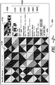
FIG. 2 is an illustration of a graphic display on the computer monitor, showing an embodiment of subject design layout display, a pallet display, and a tool layout display; -
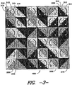
FIG. 3 is an illustration of the subject design layout display fromFIG. 2 , with the overlay container zones and graphics visible for illustrative purposes; -
FIG. 4 is an illustration of an embodiment of the graphic display fromFIG. 2 , with the overlay graphics of a single overlay container activated by a hover event; -
FIG. 5 is an illustration of an alternative graphic display, an environmental mask, such as a room scene, with a window in which to display the subject design layout display, such as a floor layout, and the environmental mask and subject design layout being in a three dimensional perspective view; -
FIG. 6 is an illustration of the environment mask fromFIG. 5 ; -
FIG. 7 is an illustration of the subject design layout, or flooring layout, fromFIG. 5 . - The following examples further illustrate the subject matter described above but, of course, should not be construed as in any way limiting the scope thereof.
- Referring now to the figures, and in particular to
FIG. 1 , embodiments of the present invention provide a system and method for displaying agraphic display 200 including a flooring layout or room scene with a flooring layout, on a display screen or monitor 120 of acomputer system 100. Thecomputer system 100 includes a hover event, a drag event, and a computer activation event. The drag function has a start point and a finish point. - For some computer devices, such as a standard computer with a mouse controlling a curser, the hover event occurs wherever a curser is positioned in the desired location in the display of the monitor. In such devices, the start point of the drag function can occur at the location of the curser upon the down click of a mouse button, with the finish point occurring at the location of the curser upon the up click of the mouse button. A computer activation event on such a device will typically occur in the location of the curser upon the up click of the mouse button.
- For some computer devices, such as a touch device computer, the hover event occurs at the location that a tap pressure is applied to the monitor or display screen of the device. For such devices, the start point of a drag function can occur at the initial point of contact or application of pressure to the monitor of the device, with the finish point occurring at the location on the monitor where the contact or pressure is removed from the monitor after movement across the display screen. A computer activation event on such a device will typically occur in the location in which a quick tap, or application and release of pressure, is applied to the display screen.
- Still referring to
FIG. 1 , a computer program and computer files are used by thecomputer system 100 for creating and manipulating thegraphic display 200 on themonitor 120. Typically, when thecomputer 100 is connected to theinternet 99 and sends a request to ahost computer 98 for a page displaying thegraphic display 200, the computer program instructions and files are downloaded from thehost computer 98, or hostcomputers internet 99 to thecomputer 100 as a "client" computer. Thecomputer 100 then places the program instructions and files in thecomputer 100, a processor of processors of the computer use the program instructions and files to generate thegraphic display 200 on themonitor 120. The program instructions can be code in languages such as HTML5, CSS3, Javascript, jQuery 1.7 and above, JSON, and any other language that would allowcomputer 100 to create thegraphic display 200 and enable the functionalities. The downloaded program instructions operate within a standard browse in thecomputer 100, such as Google Chrome 16 or higher, Apple Safari 5 or higher, Mozilla Firefox 10 and higher, and Microsoft IE 7 (with Google Chrome Frame) or higher. During a session of using thegraphic display 200, thecomputer 100 can return to thehost computer 98, or hostcomputers internet 99 to obtain additional computer program instructions and/or files, as needed by thecomputer 100 for thegraphic display 200 as described below. - Referring now to
FIG. 2 , thegraphic display 200 generally includes a subjectdesign layout display 1000, atile pallet display 4000, and atool layout display 5000. Referring now toFIGS. 3 and4 , the subjectdesign layout display 1000 is drawn in such a manner to illustrate the components of the subjectdesign layout display 1000. The subjectlayout design display 1000 includes acanvas layer 2000 and anoverlay layer 3000. Thecanvas layer 2000 has a plurality oftile graphics 2100. Theoverlay layer 3000 has a plurality ofoverlay containers 3100; eachoverlay container 3100 corresponding with atile graphic 3100 in thecanvas layer 3000. Theoverlay containers 3100 in theoverlay layer 3000 each have container zones and an overlay graphic. Theoverlay layer 3000 is transparent, with the exception of the overlay graphics when activated. As illustrated inFIG. 3 , the overlay graphics in all overlay containers theoverlay layer 3000 are visible; however, typically only the graphics forsingle overlay container 3100 would be visible during certain events, as will be described below. Additionally, as illustrated inFIG. 3 , the boundaries of the container zones are demonstrated with dashed lines for illustration purposes; however, the boundaries of the container zones are typically not illustrated or visible in thesubject design display 1000. InFIG 4 , there is shown thegraphic display 200 fromFIG. 2 , with the overlay graphics for a singleoverlay layer container 3100 activated for display. - Referring now to
FIGS. 3 and4 , thecanvas layer 2000 comprises a plurality oftile graphics 2100 arranged in a grid or matrix. In one embodiment, thecanvas layer 2000 is an HTML5 element that is manipulated and controlled via HTML, Javascript, jQuery, and CSS3. Each of thetile graphics 2100 represent a section of the floor layout and are categorized by predetermined tile patterns.Tile graphics 2100 from a particular tile pattern will have a design with common design elements. Thetile graphics 2100 are further categorized by color scheme. Thetile graphics 2100 of a particular tile pattern and color scheme will have the same design astile graphics 2100 from the same tile pattern with a different color scheme, but a different use of colors. Additionally,tile graphics 2100 with a particular tile pattern and a particular color scheme can have accents. Accents can betile graphics 2100 with variations of the colors for the tile pattern with that color scheme, the addition ofmore tile graphics 2100 in the tile pattern and color scheme (having same tile pattern with variations in the colors of the design), or both. - Still referring to
FIGS. 3 and4 , the grid in thecanvas layer 2000 can be a conventional square grid with even rows and columns, or an unconventional grid such as an ashlar pattern. In one example of an ashlar pattern, the grid or matrix the rows in a column are offset from the rows of adjacent columns. In another example of an ashlar patter, the columns in a row are offset from the columns of adjacent rows. Thetile graphics 2100 are placed in the grid of thecanvas layer 2000 with a particular angular orientation or rotational angle 2200. Thetile graphics 2100 in thecanvas layer 2000 can all be oriented in the same angular direction, or can be oriented different from one tile graphic 2100 to the next in thecanvas layer 2000. For example, thetile graphics 2100 in a group of four can be oriented in quarter turn pattern, with each graphic pointing in the same clockwise or counterclockwise direction, with alltile graphics 2100 in alternating rows or columns pointing in opposite directions, or with thetile graphics 2100 randomly oriented throughout thecanvas 2000. - Referring still to
FIGS. 3 and4 , theoverlay layer 3000 comprises a plurality ofoverlay containers 3100 in a grid or matrix matching the grid or matrix of thetile graphics 2100 in thecanvas layer 2000. In one embodiment, theoverlay layer 3000 comprises HTML div container elements for theoverlay containers 3100, that is manipulated and controlled via HTML, Javascript, jQuery, and CSS3. Eachoverlay container 3100 corresponds with the tile graphic 2100 with same position in thecanvas layer 2000. Each of theoverlay containers 3100 include at least one overlay container zone 3110 with an associated overlay function. However, theoverlay containers 2100 will preferably include multiple overlay container zones, each with an associated overlay function. The overlay functions comprise functions that manipulate the associated tile graphic 2100 in thecanvas layer 2000 upon a computer activation event over the container zone associated with the overlay function. - The overlay container zones of the
overlay containers 3100 inFIGS. 3 and4 include a firstrotational zone 3111 and a secondrotational zone 3112. The overlay functions of theoverlay containers 2100 include a first rotational function associated with the firstrotational zone 3111 and a second rotational function associated with the secondrotational zone 3112. The first rotational function of theoverlay container 3100 rotates the orientation of the corresponding tile graphic 2100 in thecanvas layer 2000 ninety degrees clockwise when the computer activation event occurs over the firstrotational zone 3111 of thatoverlay container 3100. The second rotational function of theoverlay container 3100 rotates the orientation of the corresponding tile graphic 2100 in thecanvas layer 2000 ninety degrees counterclockwise when the computer activation event occurs over the secondrotational zone 3112 of thatoverlay container 3100. - The
overlay containers 3100 inFIGS. 3 and4 , also include anexchange zone 3113 and an exchange function associated with theexchange zone 3113. The exchange function is operated by the drag event of thecomputer 120. When the start point of a drag event occurs over theexchange zone 3113 of afirst overlay container 3100, the location of thefirst overlay container 3100 in theoverlay layer 3000 and the corresponding tile graphic 2100 in thecanvas layer 2000 are placed in a memory of thecomputer 100. Then, when the finish point of that drag event occurs over theexchange zone 3113 of asubsequent overlay container 3100 the tile graphic 2100 associated with thesubsequent overlay container 3100 is replaced with the tile graphic 2100 associated with thefirst overlay container 3100 and the tile graphic 2100 associated with thefirst overlay container 3100 is replaced with the tile graphic 2100 associated with thesubsequent overlay container 3100. In one embodiment, an image of the first tile graphic 3100 will drag across thegraphic display 200 with the drag event until the finish point of that drag event is completed, at which time the dragging image will delete. - Still referring to
FIGS. 3 and4 , as illustrated each of theoverlay containers 3100 also include overlay graphic that provides graphical information about theoverlay container 3100, such as graphical information about the overlay functions. The overlay graphics of theoverlay containers 3100 have a first rotational graphic 3131 located in the firstrotational zone 3111 of theoverlay containers 3100 that points in a clockwise direction, and a second rotational graphic 3132 located in the secondrotational zone 3112 of theoverlay containers 3100 that point in a counterclockwise direction. The overlay graphics of theoverlay containers 3100 also include an exchange graphic 3133 located within theexchange zone 3113. In one embodiment the overlay graphic in eachoverlay container 3100 include an outline graphic 3134 illustrating the border of theoverlay container 3100 in theoverlay layer 3100 and associated tile graphic 2100 in thecanvas layer 2100. In one embodiment, the overlay graphic of eachoverlay container 3100 are transparent until a hover event occurs over anoverlay container 3100, at which point the overlay graphic of thatparticular overlay container 3100 become visible. Although the overlay graphics of the overlay containers are described as a single graphic having a first rotational graphic 3131, second rotational graphic 3132, an exchange graphic 3133, and an outline graphic 3134, each of the individual portions of the overlay graphic can be a single graphic by itself. Additionally, one or more of the components of the overlay graphics can be a stylized hover effect using called out from the programming language. - Referring back now to
FIG. 2 , thepallet display 4000 is shown adjacent to the subjectdesign layout display 1000 in thegraphic display 200 on themonitor 120. In one embodiment, thepallet display 4000 is an HTML5 element that is manipulated and controlled via HTML, Javascript, jQuery, and CSS3. Thepallet display 4000 has a tilegraphic icon 4100 for each of thetile graphics 2100 in thecanvas layer 2000 having a particular tile pattern, color scheme, and accent. A particular tile graphic 3100 may appear more than once in thecanvas layer 3000, but will only have one associated tilegraphic icon 4100 in thepallet display 4000. The tilegraphic icons 4100 are grouped in thepallet display 4000 by a common tile pattern. - Still referring to
FIG. 2 , in one embodiment the tilegraphic icons 4100 in thetile pallet display 4000 can be used as a source for placingtile graphics 2100 into thecanvas 2000. In such an embodiment, by activating the start point of a drag event over agraphic tile icon 4100 and then the finish point over anoverlay container 3100, the tile graphic 2100 in the location of the canvas grid corresponding withoverlay container 3100 for which the finish point occurred is replaced with a tile graphic 2100 associated with the tilegraphic icon 4100 for which the start point occurred. - Referring still to
FIG. 2 , there is shown atool layout display 5000 adjacent to the subjectdesign layout display 1000 in thegraphic display 200. In one embodiment, each of the tools in thetool layout display 5000 comprise an HTML5 element that is manipulated and controlled via HTML, Javascript, jQuery, and CSS3. As illustrated inFIG. 2 , thetool layout display 5000 includes tile pattern indicia 5100,color scheme indicia 5200, andaccent indicia 5300. Thetile pattern indicia 5100 include a representation for each tile pattern available for use in thecanvas layer 2100 of the subjectdesign layout display 1000. Thecolor scheme indicia 5200 include indicia for each color scheme available for the tile patterns in thetile pattern indicia 5100. The accent indicia 5300 include indicia for each accent scheme available for each tile pattern and color scheme combination. Each tile pattern will have a default color scheme and accent associated with the particular tile pattern. - Referring now to
FIGS. 2 and3 , thetile pattern indicia 5100 can be used to change thetile graphics 2100 in thecanvas layer 2000 and the associated tilegraphic icons 5100 in thetile pallet display 5000. When the computer activation event occurs over atile pattern indicia 5100 in thetool layout display 5000, and there are notile graphics 2100 in thecanvas layer 2000 having the tile pattern associated with that tile pattern indicia 5100, thecanvas layer 2000 is reconfigured to include thetile graphics 2100 associated with the tile pattern having the default color scheme and default accent scheme and the tilegraphic icons 4100 associate with theadditional tile graphics 2100 in thecanvas 2000 are added to thetile pallet display 4000. When the computer activation event occurs over atile pattern indicia 5100 in thetool layout display 5000, and thecanvas layer 2100 includestile graphics 2100 having the tile pattern associated with the particular tile pattern indicia 5100, thecanvas layer 2000 is reconfigured to without thetile graphics 2100 associated with that tile pattern and the tilegraphic icons 4100 associate with theadditional tile graphics 2100 are removed from thetile pallet display 4000. In the embodiment illustrated inFIGS. 2 and3 , the tile pattern indicia 5100 includes indicia for all available tile patterns, but indicia for tile patterns not currently in use have a reduced opacity to indicate that the particular pattern is not active or in use. - Referring still to
FIGS. 2 and3 , thecolor scheme indicia 5200 can be used to change thetile graphics 2100 in thecanvas layer 2000 and the associated tilegraphic icons 5100 in thetile pallet display 5000, to tilegraphics 2100 and tile graphic icons 510o having a the same tile pattern with a different color scheme. To change the color scheme of thetile graphics 2100 in thecanvas 2000 and the associated tilegraphic icons 4100 in thetile pallet display 4000, the computer activation event is first used to select the tile pattern indicia 5100 of the tile pattern in which the color scheme will be changed. Once the tile pattern indicia 5100 has been selected, activating the computer activation event over thecolor scheme indicia 5200 representing the desired color scheme will change the tilegraphic icons 5100 in thetile pallet display 5100 to representations of thetile graphics 2100 having the particular tile pattern and color scheme and thecanvas layer 2000 will be reconfigured to usetile graphics 2100 with the selected tile pattern and selected color scheme. Typically, selection of a new color scheme could only replace thetile graphics 2100 in thecanvas 2000 having the tile pattern withtile graphics 2100 having the same tile pattern and a different color scheme, or could redraw thecanvas layer 2000 with the selected tile patterns. However, the selection of a new color scheme could result in the tile pattern having fewer ormore tile graphics 2100 for that particular color scheme, in which case thecanvas layer 2000 will be redrawn using the selectedtile graphics 2100. - Still referring to
FIGS. 2 and3 , theaccent indicia 5300 can be used to change thetile graphics 2100 in thecanvas layer 2000 and the associated tilegraphic icons 5100 in thetile pallet display 5000 to tilegraphics 2100 and tilegraphic icons 5100 having the same tile pattern and color scheme, but a different accent scheme. To change the accent scheme of thetile graphics 2100 in thecanvas 2000 and the associated tilegraphic icons 4100 in thetile pallet display 4000, the tile pattern and color scheme to be changed must first be selected. The tile pattern is selected by activation of a computer activation event over the tile pattern indicia 5100 of the desired tile pattern. The color scheme is then selected by activation of a computer activation event over thecolor scheme indicia 5200 of the desired color scheme. Once the tile pattern and color scheme have been selected, activation of the computer activation event over theaccent scheme indicia 5300 representing the desired accent scheme, will regenerate thecanvas layer 2000 usingtile graphics 2100 with the selected tile pattern, color scheme, and accent scheme, and the tilegraphic icons 5100 in thetile pallet display 5100 will change to representations of thetile graphics 2100 in thecanvas layer 2000 after the regeneration. Typically, selection of an accent scheme will result in the tile pattern havingmore tile graphics 2100 for that particular color scheme and accent scheme, in which case thecanvas layer 2000 will be redrawn using the selectedtile graphics 2100. Similarly, if the selection of an accent scheme will result in the tile pattern havingfewer tile graphics 2100 for that particular color scheme and accent scheme, thecanvas layer 2000 will be redrawn using the selectedtile graphics 2100. If the selection of an accent scheme results in the same number oftile graphics 2100, thecanvas layer 2000 can be redrawn with the selectedtile graphics 2100 or could only have thenew tile graphics 2100 replace theold tile graphics 2100 in thecanvas 2000 that change because of the selection. - Referring still to
FIGS. 2 and3 , thetool layout display 5000 further includes tilegraphic orientation indicia 5400, or installation method, each with an associated orientation function for each tilegraphic orientation indicia 5400. As previously discussed, each of thetile graphics 2100 in thecanvas 2000 is oriented in a particular direction. The orientation functions associated with the tilegraphic orientation indicia 5400 will rotate thetile graphics 2100 in thecanvas layer 2000 according to the orientation function. As illustrated, the tilegraphic orientation indicia 5400 include "monolithic" orientation indicia and "random" orientation indicia. A monolithic orientation function associated with the monolithic orientation indicia will align thetile graphics 2100 in thecanvas layer 2000 to an orientation with the same direction upon activation of a computer activation event over the monolithic orientation indicia. A random orientation function associated with the random orientation indicia will change the orientation of thetile graphics 2100 in thecanvas layer 2000 to a random orientation upon activation of a computer activation event over the random orientation indicia. - Still to
FIGS. 2 and3 , thetool layout display 5000 further includes tile pattern grouping indicia 5500, or pattern display, with associated grouping functions. As previously discussed, each of thetile graphics 2100 in thecanvas 2000 are arranged according to a grid or matrix. The grouping functions arrange thetile graphics 2100 in the grid or matrix of thecanvas layer 2000 according to the selected grouping function. As illustrated, the tilepattern grouping indicia 5500 include a "blend" grouping indicia and a "separation" grouping indicia. Upon activation of a computer activation event over the blend grouping indicia the blend grouping function associated with the blend grouping indicia arranges thetile graphics 2100 in random placement within the grid or matrix of thecanvas layer 2000 without regard to the tile pattern of the tile graphic 2100. Upon activation of a computer activation function over the separation grouping indicia the separation grouping function associated with the separation grouping indicia arranges thetile graphics 2100 in within the grid or matrix of thecanvas layer 2000 in groups of common tile patterns. In one embodiment, the separation grouping function organizes thetile graphics 2100 in the grid or matrix of thecanvas layer 200 with each column of the grid or matrix having only tilegraphics 2100 with a particular tile pattern. - Referring still to
FIGS. 2 and3 , thetool layout display 5000 further includesgrid size indicia 5600, with an associated grid size function. As previously discussed, each of thetile graphics 2100 in thecanvas 2000 are arranged according to a grid or matrix. Upon activation of a computer activation event over a particulargrid size indicia 5600, the associatedgrid size function 5600 will change the size of the grid or matrix in thecanvas layer 2000 and theoverlay layer 3000 to the grid size according to thegrid size indicia 5600, and redraw thecanvas layer 2000 and theoverlay layer 3000 with the number oftile graphics 2100 andoverlay cells 3100 required for the new grid size. - Referring now to
FIG. 5 , there is shown another embodiment of thegraphic display 200 with the subjectdesign layout display 1000 in three dimensional perspective view and having anenvironmental mask 7000 over the subjectdesign layout display 1000. As with thesubject design layout 1000 inFIG. 2 , in one embodiment the subjectdesign layout display 1000 and environmental mask 7000ifFIG. 5 comprise an HTML5 element that is manipulated and controlled via HTML, Javascript, jQuery, and CSS3. Theenvironmental mask 7000 has a perspective graphic design representing aroom layout 7100, as illustrated inFIG. 6 , with atransparent window 7200 in the region represented by the floor of the room. Theenvironmental mask 7000 is disposed over the subject design layout, or floor layout,design 1000 appearing through thetransparent window 7200. As illustrated inFIG. 7 , the subject layout display (or floor layout display)1000 includes thesame canvas layer 2000 andoverlay layer 3000 as described above with association withFIGS. 2 through 4 above, with the same features and functions, but with the gird or matrix of thecanvas layer 2000 andoverlay layer 3000 in perspective view. Thegraphic display 200 illustrated inFIG. 5 also includes thetile pallet display 4000 with the same features and functions as described above in association withFIG. 2 above. Thegraphic display 200 illustrated inFIG. 5 further includes an alternative tool layout display 5000'. - Still referring to
FIG. 5 , the alternative tool layout display 5000' includes the sametile layout indicia 5100,color scheme indicia 5200,accent indicia 5300, tilegraphic orientation indicia 5400, andtile pattern indicia 5500 as thetool layout display 5000 inFIGS. 2 , with the same features and functions. However, the alternative tool layout display 5000' inFIG. 5 does not include thegrid size indicia 5600. The alternative tool layout display 5000' inFIG. 5 does includeenvironmental mask indicia 5700. Theenvironmental mask indicia 5700 represent differentenvironmental masks 7000 for use in the subjectdesign layout display 1000, eachenvironmental mask 7000 having a differentperspective room design 7100 andtransparent window 7200 in which to display thefloor layout 1000. As illustrated, theenvironmental mask indicia 5700 include indicia for an open office, a reception room, an elevator lobby, and a small and large conference room. Upon activation of a computer activation event over a particularenvironmental mask indicia 5700, theenvironmental mask 7000 in thegraphic display 200 is change to an environmental mask having aroom design 7100 andtransparent window 7200 associated with the particularenvironmental mask indicia 5700, and thecanvas layer 2000 andoverlay layer 3000 of theflooring layout display 1000 are changed to a predetermined grid size and location specified in association with the selectedenvironmental mask 7000. - Thus, embodiments of the present invention include an interactive single display comprising a configurable floor plan layout matrix (e.g. main carpet tile display area). The floor layout matrix may be customized by the end-user. For example, a default layout matrix may be 12x10, but it may also be customized to a maximum of 20x20, a minimum of 4x4, and any matrix sizes in between. Other customization options include masking off areas of the floor plan, such as columns and other excluded areas.
- Additionally, multiple design collections of carpet tiles are achievable. These collections may reside together within a single display area. Collection integrity is also maintained regardless of layouts being contiguous or in separate areas.
- Each design collection may occupy a user defined and customizable area. The area may be contiguous or separated within the main layout. The layout is arranged according to its pattern design matrix (e.g. 4x4, 3x3, etc.) within its user defined area. The design collection may be re-colored by dragging and dropping colors from its associated color palette. Design collections may be dynamically reconfigured according to its rule sets (Monolithic, Random, Quarter-Turn, Ashlar, etc.).
- All carpet tiles in the display can be individually manipulated by the end-user. According to each collection/design rule set, the carpet tiles in the display may be rotated in 90 degree increments. They may be dragged and/or swapped within its collection boundaries.
- The end-user can further custom design the carpet tiles display. For example, the end-user can overlay the supplied furniture symbols to simulate a planned environment. Or, the end-user may dynamically create a custom install map to help with installation planning. The custom designed space may be saved by the end-user as a "jpg" graphic file for use in other design and/or communication applications. A "tear sheet" may be printed by the end-user that defines which tiles are used with product identification in order to expedite the ordering process.
- The use of the terms "a" and "an" and "the" and similar referents in the context of describing the subject matter of this application (especially in the context of the following claims) are to be construed to cover both the singular and the plural, unless otherwise indicated herein or clearly contradicted by context. The terms "comprising," "having," "including," and "containing" are to be construed as openended terms (i.e., meaning "including, but not limited to,") unless otherwise noted. Recitation of ranges of values herein are merely intended to serve as a shorthand method of referring individually to each separate value falling within the range, unless otherwise indicated herein, and each separate value is incorporated into the specification as if it were individually recited herein. All methods described herein can be performed in any suitable order unless otherwise indicated herein or otherwise clearly contradicted by context. The use of any and all examples, or exemplary language (e.g., "such as") provided herein, is intended merely to better illuminate the subject matter of the application and does not pose a limitation on the scope of the subject matter unless otherwise claimed. No language in the specification should be construed as indicating any non-claimed element as essential to the practice of the subject matter described herein.
Claims (18)
- A method of generating a graphic display (200) including a floor layout or a room scene with a floor layout on a monitor of a computer system, the computer system including a hover event, a drag event with a start point activation and a finish point activation for the graphic display, the method comprising the steps of:displaying in the graphic display on the monitor a subject design layout comprising:a canvas layer (2000) having tile graphics (2100) arranged according to a predetermined grid, each tile graphic representing a section of the floor layout and categorized by predetermined tile patterns;an overlay layer (3000) having overlay containers (3100) arranged in a grid correlating to the grid of tile graphics on the canvas layer, each overlay container being associated with the tile graphic located in a corresponding location of the canvas layer, each overlay container having overlay functions and an overlay graphic, the overlay functions in each overlay container comprising:an exchange function associated with an exchange zone (3113) of the overlay container, the overlay graphic comprising an exchange graphic (3133) located in the exchange zone of the overlay container, andthe overlay graphic in each overlay container being transparent until the hover occurs over the associated overlay container,wherein the tile graphic associated with a first overlay container in the exchange zone of which the finish point activation of the drag event occurs is exchanged with the tile graphic associated with a second overlay container in the exchange zone of which the start point activation of the drag event occurred.
- The method according to Claim 1, wherein the overlay graphics further include an outline graphic illustrating the border of the associated tile graphic.
- The method according to Claim 1, wherein the computer system further includes a computer activation event for the graphic display, and wherein the overlay functions in each overlay container further comprise a first rotational function associated with a first rotational zone of the overlay container, the overlay graphics in each overlay container including a first rotational graphic positioned in the first rotational zone of the overlay container, wherein the tile graphic associated with a particular overlay container is rotated a predetermined amount in a first direction when the computer activation event occurs over the first rotational zone of the associated overlay container.
- The method according to Claim 3, wherein the overlay functions of each overlay container further comprise a second rotational function located in a second rotational zone of the overlay container and the overlay graphics of the associated overlay container further comprise a second rotational graphic located in the second rotational zone, and wherein the tile graphic associated with a particular overlay container is rotated in a second direction when the computer activation event occurs over the second rotational zone of the associated overlay container.
- The method according to Claim 1, wherein the computer system further includes a computer activation event for the graphic display, and the method further includes the step of displaying a tool layout display in the graphic display on the monitor, the tool layout display comprising a plurality of grid size indicia, wherein occurrence of the computer activation event over a particular grid size indicia changes the size of the grid of the canvas layer and the overlay layer to a grid size associated with the particular grid size indicia.
- The method according to Claim 1, comprising:displaying a room scene in the graphic display, the room scene including:an environment mask having a perspective room design representing a portion of the room scene with a transparent window in the perspective room design for representing at least a portion of the floor in the room scene,a floor layout display associated with the environment mask, the floor layout display having the canvas layer and the overlay layer,the canvas layer having tile graphics with a perspective shape and arranged according to a predetermined perspective grid, the tile graphics representing a portion of the floor,the overlay layer having overlay containers with a perspective shape and arranged in a perspective grid correlating to the grid of tile graphics on the canvas layer,wherein environment mask is positioned over the floor layout display and at least a portion of the floor layout display is visible through the transparent window of the environmental mask.
- The method according to Claim 6, wherein the overlay containers each further comprise an outline graphic illustrating the border of the tile graphic canvas associated with the overlay container, and wherein the outline graphic in each overlay container are transparent until the hover event occurs over the associated overlay container.
- The method according to Claim 1 or 6, where in the grid for the tile graphics in the canvas layer and the overlay cells in the overlay layer is an ashlar grid.
- The method according to Claim 6, wherein the computer system further includes a computer activation event for the graphic display, and wherein the overlay containers each comprise a first rotational zone and the overlay functions each comprise a first rotational function located within the first rotational zone, and wherein the tile graphic associated with a particular overlay container is rotated a predetermined amount in a first direction when the computer activation event occurs over the first rotational zone of the associated overlay container.
- The method according to Claim 9, wherein the overlay containers each further comprising a first rotational graphic located in the first rotational zone, the first rotational graphic being transparent unless the curser is positioned over the associated outline container, or wherein the overlay containers each further include a second rotational zone and the overlay functions each further includes a second rotational function located within the second rotational zone, and wherein the tile graphic associated with a particular overlay container is rotated a predetermined amount in a second direction when the curser is positioned over the first rotational zone of the particular overlay container and the second activation function of the computer system is activated.
- The method according to Claim 10, wherein the overlay containers each further comprising a first rotational graphic located in the first rotational zone and a second rotational graphic in the second rotational zone, and wherein the first rotational graphic and the second rotational graphic in each overlay container are transparent until the hover event occurs over the associated overlay container.
- The method according to Claim 1 or 6, further including the step of displaying a tile pallet display in the graphic display,
the tile pallet display containing tile graphic icons representing a set of potential tile graphics for the canvas layer of the subject design layout, wherein the tile graphic associated with an overlay container in which the finish point of the drag event occurs is exchanged with the tile graphic associated with a tile graphic icon in which the start point of drag event has occurred, or
the tile pallet display containing tile graphic icons representing the tile graphics in the canvas layer of the subject design layout, the tile graphic icons being in groups of related tile patterns. - The method according to Claim 12, wherein the tile graphics of each tile pattern are grouped together in the canvas layer by column.
- The method according to Claim 12, wherein the computer system further includes a computer activation event for the graphic display, and the method further includes the step of displaying a tool layout display in the graphic display, the tool layout display comprising a plurality of tile pattern indicia with each tile pattern indicia representing a different tile pattern and each color scheme indicia representing different color schemes for each tile pattern, and further including the steps of selecting a tile pattern indicia and, upon selection of a color scheme indicia by occurrence of the computer activation event over the color scheme indicia, changing the graphic tiles in the canvas layer associated with the selected tile pattern to graphic tiles associated with the same tile pattern having the color scheme indicated by the selected color scheme indicia and changing the tile graphic icons in the tile pallet display associated with the selected tile pattern to tile graphic icons associated with the same tile pattern having the color scheme indicated by the selected color scheme indicia.
- The method according to Claim 12, wherein the computer system further includes a computer activation event for the graphic display, and the method further includes the step of displaying a tool layout display in the graphic display, the tool layout display comprising tile pattern indicia with each tile pattern indicia representing a different tile pattern, and further including
the step of, upon occurrence of the computer activation event over a particular tile indicia, removing from the tile pallet display the tile icons associated with that tile pattern indicia and replacing the tile graphics in the canvas layer of the subject design layout with tile graphics associated with the remaining tile graphic icons remaining in the tile pallet display, or
the step of, upon occurrence of the computer activation event over a particular tile indicia, adding to the tile pallet display the tile icons associated with the selected tile pattern indicia and replacing the tile graphics in the canvas layer of the subject design layout with tile graphics associated with the tile graphic icons in the tile pallet display. - The method according to Claim 1 or 6, wherein the computer system further includes a computer activation event for the graphic display, and the method further includes the step of displaying a tool layout display in the graphic display, the tool layout display comprising a tile graphic orientation indicia, wherein occurrence of the computer activation event over the tile graphic orientation icon changes the angular direction of the tile graphics in the canvas layer to a uniform direction or to a non-uniform random direction.
- The method according to Claim 1 or 6, wherein the computer system further includes a computer activation event for the graphic display, and the method further includes the step of displaying a tool layout display in the graphic display on the monitor, the tool layout display comprising a tile pattern grouping indicia,
wherein occurrence of the computer activation event over the tile pattern grouping indicia changes the placement of tile graphics in the canvas layer to a non-uniform random placement in the grid of the canvas layer, or
wherein occurrence of the computer activation event over the tile pattern grouping indicia changes the placement of tile graphics in the canvas layer into groups by tile pattern in the grid of the canvas layer, or
wherein occurrence of the computer activation event over the tile pattern grouping indicia changes the placement of tile graphics in the canvas layer into groups by tile pattern in the grid of the canvas layer, the groups being columns in the grid of the canvas layer with each column containing only the tile graphics from a single tile pattern. - The method according to Claim 6, wherein the computer system further includes a computer activation event for the graphic display, and the method further includes the step of displaying a tool layout display in the graphic display on the monitor, the tool layout display comprising a plurality of environment mask indicia representing different environment masks for different room scenes, wherein upon the occurrence of the computer activation event over a particular environment mask size indicia changes the environmental mask in the floor layout display to the environmental mask associated with the particular environmental mask indicia.
Applications Claiming Priority (3)
| Application Number | Priority Date | Filing Date | Title |
|---|---|---|---|
| US201261604602P | 2012-02-29 | 2012-02-29 | |
| US13/775,287 US9454835B2 (en) | 2012-02-29 | 2013-02-25 | System and method for displaying and manipulating a floor layout display on a computer |
| PCT/US2013/027900 WO2013130519A1 (en) | 2012-02-29 | 2013-02-27 | System and method for displaying and manipulating a floor layout display on a computer |
Publications (2)
| Publication Number | Publication Date |
|---|---|
| EP2820535A1 EP2820535A1 (en) | 2015-01-07 |
| EP2820535B1 true EP2820535B1 (en) | 2020-08-26 |
Family
ID=49002373
Family Applications (1)
| Application Number | Title | Priority Date | Filing Date |
|---|---|---|---|
| EP13709012.2A Active EP2820535B1 (en) | 2012-02-29 | 2013-02-27 | Method for displaying and manipulating a floor layout display on a computer |
Country Status (5)
| Country | Link |
|---|---|
| US (2) | US9454835B2 (en) |
| EP (1) | EP2820535B1 (en) |
| CN (1) | CN104145246B (en) |
| AU (1) | AU2013226199B2 (en) |
| WO (1) | WO2013130519A1 (en) |
Families Citing this family (13)
| Publication number | Priority date | Publication date | Assignee | Title |
|---|---|---|---|---|
| US9622609B2 (en) * | 2012-03-02 | 2017-04-18 | Columbia Insurance Company | Pattern carpet tiles and methods of making and using same |
| US9349123B1 (en) * | 2012-10-04 | 2016-05-24 | Amazon Technologies, Inc. | Hybrid native networked application |
| US9340982B2 (en) | 2013-03-13 | 2016-05-17 | Columbia Insurance Company | Patterned tiles and floor coverings comprising same |
| US10121270B2 (en) * | 2013-07-01 | 2018-11-06 | Facebook, Inc. | Flexible image layout |
| CN104268944A (en) * | 2014-09-09 | 2015-01-07 | 北京尔宜居科技有限责任公司 | Automatic display method of decorative tile and marble laying scheme |
| USD786300S1 (en) * | 2014-12-16 | 2017-05-09 | Bioinventors & Entrepeneurs Network Llc | Display screen or portion thereof with a graphical user interface |
| US9830702B2 (en) | 2015-10-22 | 2017-11-28 | International Business Machines Corporation | Dynamic real-time layout overlay |
| US10163184B2 (en) * | 2016-08-17 | 2018-12-25 | Adobe Systems Incorporated | Graphics performance for complex user interfaces |
| CH712889A1 (en) * | 2016-09-08 | 2018-03-15 | Thuering Ag | System for the presentation of different floor coverings. |
| US10783681B2 (en) | 2017-09-13 | 2020-09-22 | International Business Machines Corporation | Artificially tiltable image display |
| US11151314B2 (en) * | 2018-10-19 | 2021-10-19 | Sap Se | Extensible grid layout |
| US12482034B2 (en) * | 2021-08-13 | 2025-11-25 | FeltRight, LLC. | Software for tile pattern designs and assembling tile kits |
| CN116841439B (en) * | 2023-08-31 | 2023-12-15 | 深圳思谋信息科技有限公司 | Display method and device for image pixel grid, computer equipment and storage medium |
Family Cites Families (27)
| Publication number | Priority date | Publication date | Assignee | Title |
|---|---|---|---|---|
| US5966454A (en) | 1995-09-14 | 1999-10-12 | Bentley Mills, Inc. | Methods and systems for manipulation of images of floor coverings or other fabrics |
| US6931600B1 (en) | 1999-05-07 | 2005-08-16 | Autodesk, Inc. | Integrating into an application objects that are provided over a network |
| US6459435B1 (en) | 2000-01-11 | 2002-10-01 | Bluebolt Networks, Inc. | Methods, systems and computer program products for generating storyboards of interior design surface treatments for interior spaces |
| JP2003521061A (en) | 2000-01-25 | 2003-07-08 | オートデスク,インコーポレイテッド | Method and apparatus for providing and processing access to architectural drawings on the internet |
| US6572377B2 (en) | 2000-06-09 | 2003-06-03 | Cynthia H. Masters | Computerized interior design expert system |
| US7523411B2 (en) | 2000-08-22 | 2009-04-21 | Bruce Carlin | Network-linked interactive three-dimensional composition and display of saleable objects in situ in viewer-selected scenes for purposes of object promotion and procurement, and generation of object advertisements |
| US7246044B2 (en) | 2000-09-13 | 2007-07-17 | Matsushita Electric Works, Ltd. | Method for aiding space design using network, system therefor, and server computer of the system |
| US20020123942A1 (en) | 2001-03-01 | 2002-09-05 | Bridges James C. | Preview system for floor covering installations |
| US8812968B2 (en) * | 2001-05-03 | 2014-08-19 | Milliken & Company | Systems and methods for displaying and manipulating images of floor covering elements |
| US7072733B2 (en) | 2002-01-22 | 2006-07-04 | Milliken & Company | Interactive system and method for design, customization and manufacture of decorative textile substrates |
| US7277572B2 (en) | 2003-10-10 | 2007-10-02 | Macpearl Design Llc | Three-dimensional interior design system |
| US7661958B2 (en) | 2004-03-18 | 2010-02-16 | Customstart Design Ltd. | Methods and apparatus for interior design component selection |
| US20060080125A1 (en) | 2004-09-03 | 2006-04-13 | Andy Shipman | Carpet simulation method |
| US7801114B1 (en) | 2005-10-26 | 2010-09-21 | At&T Intellectual Property Ii, L.P. | Method and apparatus for providing network based interior design application |
| KR100827241B1 (en) * | 2006-12-18 | 2008-05-07 | 삼성전자주식회사 | Apparatus and method for editing a template for generating dynamic video |
| JP2008186095A (en) * | 2007-01-26 | 2008-08-14 | Canon Inc | Image processing apparatus, image processing method, and program |
| US7733351B1 (en) | 2007-02-06 | 2010-06-08 | Judith Sinnard | Method for forming an interactive image of indoor and outdoor spaces |
| US20080281561A1 (en) | 2007-05-09 | 2008-11-13 | Virtuecode Ltd | Internet Enabled Consultation System, Method and Service for Interior Design of Real and Virtual Spaces |
| US20110179066A1 (en) | 2008-06-20 | 2011-07-21 | Business Intelligence Solutions Safe B.V. | Methods, apparatus and systems for data visualization and related applications |
| EP2359282A2 (en) * | 2008-11-28 | 2011-08-24 | Fujifilm Medical Systems U.S.A. Inc. | Active overlay system and method for accessing and manipulating imaging dislays |
| JP2011010275A (en) * | 2009-05-26 | 2011-01-13 | Sanyo Electric Co Ltd | Image reproducing apparatus and imaging apparatus |
| US20110029401A1 (en) | 2009-07-28 | 2011-02-03 | Frances Champe Granger | Method Of Providing Online House Or Office Décor Related Service |
| US8683387B2 (en) | 2010-03-03 | 2014-03-25 | Cast Group Of Companies Inc. | System and method for visualizing virtual objects on a mobile device |
| JP2011238125A (en) * | 2010-05-12 | 2011-11-24 | Sony Corp | Image processing device, method and program |
| US8527891B2 (en) * | 2010-08-13 | 2013-09-03 | International Business Machines Corporation | Enabling user interactions between user interface components |
| US20120265758A1 (en) * | 2011-04-14 | 2012-10-18 | Edward Han | System and method for gathering, filtering, and displaying content captured at an event |
| US20130113904A1 (en) * | 2011-11-08 | 2013-05-09 | Capso Vision, Inc. | System and Method for Multiple Viewing-Window Display of Computed Spectral Images |
-
2013
- 2013-02-25 US US13/775,287 patent/US9454835B2/en active Active
- 2013-02-27 EP EP13709012.2A patent/EP2820535B1/en active Active
- 2013-02-27 CN CN201380011851.XA patent/CN104145246B/en active Active
- 2013-02-27 WO PCT/US2013/027900 patent/WO2013130519A1/en not_active Ceased
- 2013-02-27 AU AU2013226199A patent/AU2013226199B2/en active Active
-
2016
- 2016-02-19 US US15/047,665 patent/US10002453B2/en active Active
Non-Patent Citations (1)
| Title |
|---|
| None * |
Also Published As
| Publication number | Publication date |
|---|---|
| US10002453B2 (en) | 2018-06-19 |
| US20130222423A1 (en) | 2013-08-29 |
| CN104145246B (en) | 2017-07-14 |
| US9454835B2 (en) | 2016-09-27 |
| WO2013130519A1 (en) | 2013-09-06 |
| EP2820535A1 (en) | 2015-01-07 |
| CN104145246A (en) | 2014-11-12 |
| AU2013226199B2 (en) | 2016-01-07 |
| US20160170604A1 (en) | 2016-06-16 |
| AU2013226199A1 (en) | 2014-09-11 |
Similar Documents
| Publication | Publication Date | Title |
|---|---|---|
| US10002453B2 (en) | System and method for displaying and manipulating a floor layout display on a computer | |
| Taher et al. | Exploring interactions with physically dynamic bar charts | |
| KR101850829B1 (en) | Method for configuring a graphical user interface | |
| US7765490B2 (en) | Method and system for software applications using a tiled user interface | |
| US11048484B2 (en) | Automated responsive grid-based layout design system | |
| US10073580B2 (en) | Apparatus and method for positioning windows on a display | |
| CN104182131B (en) | Object stack | |
| JP5871333B2 (en) | Computer-implemented graphical user interface | |
| US20060156249A1 (en) | Rotate a user interface | |
| US7557804B1 (en) | Methods and apparatus for three-dimensional isographic navigation | |
| EP2024961A2 (en) | Geographic information system (gis) for displaying 3d geospatial images with reference markers and related methods | |
| EP2669781B1 (en) | A user interface for navigating in a three-dimensional environment | |
| CN101073097B (en) | Multi-body probing systems and methods | |
| US20150324068A1 (en) | User interface structure (uis) for geographic information system applications | |
| US20190065007A1 (en) | User interface comprising a plurality of display units, and method for positioning contents on a plurality of display units | |
| JP6598984B2 (en) | Object selection system and object selection method | |
| CN109716294A (en) | User interface with removable mini-tabs | |
| CN105103112A (en) | Apparatus and method for manipulating the orientation of object on display device | |
| WO2009095676A2 (en) | Input device | |
| JP2005296156A (en) | Medical image display device | |
| CN109716276A (en) | System and method for accessing visually occluded elements in a three-dimensional model | |
| US20130090895A1 (en) | Device and associated methodology for manipulating three-dimensional objects | |
| CN105046748A (en) | 3D photo frame apparatus capable of forming images in 3D geological body scenarios | |
| US20170090698A1 (en) | User interface and method for interactively selecting a display | |
| JP7242317B2 (en) | TABLE MANAGEMENT DEVICE, TABLE MANAGEMENT PROGRAM, AND TABLE MANAGEMENT METHOD |
Legal Events
| Date | Code | Title | Description |
|---|---|---|---|
| PUAI | Public reference made under article 153(3) epc to a published international application that has entered the european phase |
Free format text: ORIGINAL CODE: 0009012 |
|
| 17P | Request for examination filed |
Effective date: 20140814 |
|
| AK | Designated contracting states |
Kind code of ref document: A1 Designated state(s): AL AT BE BG CH CY CZ DE DK EE ES FI FR GB GR HR HU IE IS IT LI LT LU LV MC MK MT NL NO PL PT RO RS SE SI SK SM TR |
|
| AX | Request for extension of the european patent |
Extension state: BA ME |
|
| DAX | Request for extension of the european patent (deleted) | ||
| 17Q | First examination report despatched |
Effective date: 20160202 |
|
| STAA | Information on the status of an ep patent application or granted ep patent |
Free format text: STATUS: EXAMINATION IS IN PROGRESS |
|
| REG | Reference to a national code |
Ref country code: DE Ref legal event code: R079 Ref document number: 602013071931 Country of ref document: DE Free format text: PREVIOUS MAIN CLASS: G06F0009440000 Ipc: G06F0009451000 |
|
| GRAP | Despatch of communication of intention to grant a patent |
Free format text: ORIGINAL CODE: EPIDOSNIGR1 |
|
| STAA | Information on the status of an ep patent application or granted ep patent |
Free format text: STATUS: GRANT OF PATENT IS INTENDED |
|
| RIC1 | Information provided on ipc code assigned before grant |
Ipc: G06T 11/60 20060101ALI20200211BHEP Ipc: G06F 3/0484 20130101ALI20200211BHEP Ipc: G06F 9/451 20180101AFI20200211BHEP Ipc: G06T 19/20 20110101ALI20200211BHEP |
|
| INTG | Intention to grant announced |
Effective date: 20200305 |
|
| GRAJ | Information related to disapproval of communication of intention to grant by the applicant or resumption of examination proceedings by the epo deleted |
Free format text: ORIGINAL CODE: EPIDOSDIGR1 |
|
| STAA | Information on the status of an ep patent application or granted ep patent |
Free format text: STATUS: EXAMINATION IS IN PROGRESS |
|
| GRAP | Despatch of communication of intention to grant a patent |
Free format text: ORIGINAL CODE: EPIDOSNIGR1 |
|
| STAA | Information on the status of an ep patent application or granted ep patent |
Free format text: STATUS: GRANT OF PATENT IS INTENDED |
|
| INTG | Intention to grant announced |
Effective date: 20200615 |
|
| GRAS | Grant fee paid |
Free format text: ORIGINAL CODE: EPIDOSNIGR3 |
|
| GRAA | (expected) grant |
Free format text: ORIGINAL CODE: 0009210 |
|
| STAA | Information on the status of an ep patent application or granted ep patent |
Free format text: STATUS: THE PATENT HAS BEEN GRANTED |
|
| AK | Designated contracting states |
Kind code of ref document: B1 Designated state(s): AL AT BE BG CH CY CZ DE DK EE ES FI FR GB GR HR HU IE IS IT LI LT LU LV MC MK MT NL NO PL PT RO RS SE SI SK SM TR |
|
| REG | Reference to a national code |
Ref country code: GB Ref legal event code: FG4D |
|
| REG | Reference to a national code |
Ref country code: CH Ref legal event code: EP |
|
| REG | Reference to a national code |
Ref country code: AT Ref legal event code: REF Ref document number: 1307001 Country of ref document: AT Kind code of ref document: T Effective date: 20200915 |
|
| REG | Reference to a national code |
Ref country code: IE Ref legal event code: FG4D |
|
| REG | Reference to a national code |
Ref country code: DE Ref legal event code: R096 Ref document number: 602013071931 Country of ref document: DE |
|
| REG | Reference to a national code |
Ref country code: LT Ref legal event code: MG4D |
|
| PG25 | Lapsed in a contracting state [announced via postgrant information from national office to epo] |
Ref country code: FI Free format text: LAPSE BECAUSE OF FAILURE TO SUBMIT A TRANSLATION OF THE DESCRIPTION OR TO PAY THE FEE WITHIN THE PRESCRIBED TIME-LIMIT Effective date: 20200826 Ref country code: GR Free format text: LAPSE BECAUSE OF FAILURE TO SUBMIT A TRANSLATION OF THE DESCRIPTION OR TO PAY THE FEE WITHIN THE PRESCRIBED TIME-LIMIT Effective date: 20201127 Ref country code: HR Free format text: LAPSE BECAUSE OF FAILURE TO SUBMIT A TRANSLATION OF THE DESCRIPTION OR TO PAY THE FEE WITHIN THE PRESCRIBED TIME-LIMIT Effective date: 20200826 Ref country code: NO Free format text: LAPSE BECAUSE OF FAILURE TO SUBMIT A TRANSLATION OF THE DESCRIPTION OR TO PAY THE FEE WITHIN THE PRESCRIBED TIME-LIMIT Effective date: 20201126 Ref country code: BG Free format text: LAPSE BECAUSE OF FAILURE TO SUBMIT A TRANSLATION OF THE DESCRIPTION OR TO PAY THE FEE WITHIN THE PRESCRIBED TIME-LIMIT Effective date: 20201126 Ref country code: SE Free format text: LAPSE BECAUSE OF FAILURE TO SUBMIT A TRANSLATION OF THE DESCRIPTION OR TO PAY THE FEE WITHIN THE PRESCRIBED TIME-LIMIT Effective date: 20200826 Ref country code: LT Free format text: LAPSE BECAUSE OF FAILURE TO SUBMIT A TRANSLATION OF THE DESCRIPTION OR TO PAY THE FEE WITHIN THE PRESCRIBED TIME-LIMIT Effective date: 20200826 Ref country code: PT Free format text: LAPSE BECAUSE OF FAILURE TO SUBMIT A TRANSLATION OF THE DESCRIPTION OR TO PAY THE FEE WITHIN THE PRESCRIBED TIME-LIMIT Effective date: 20201228 |
|
| REG | Reference to a national code |
Ref country code: NL Ref legal event code: MP Effective date: 20200826 |
|
| REG | Reference to a national code |
Ref country code: AT Ref legal event code: MK05 Ref document number: 1307001 Country of ref document: AT Kind code of ref document: T Effective date: 20200826 |
|
| PG25 | Lapsed in a contracting state [announced via postgrant information from national office to epo] |
Ref country code: IS Free format text: LAPSE BECAUSE OF FAILURE TO SUBMIT A TRANSLATION OF THE DESCRIPTION OR TO PAY THE FEE WITHIN THE PRESCRIBED TIME-LIMIT Effective date: 20201226 Ref country code: PL Free format text: LAPSE BECAUSE OF FAILURE TO SUBMIT A TRANSLATION OF THE DESCRIPTION OR TO PAY THE FEE WITHIN THE PRESCRIBED TIME-LIMIT Effective date: 20200826 Ref country code: NL Free format text: LAPSE BECAUSE OF FAILURE TO SUBMIT A TRANSLATION OF THE DESCRIPTION OR TO PAY THE FEE WITHIN THE PRESCRIBED TIME-LIMIT Effective date: 20200826 Ref country code: LV Free format text: LAPSE BECAUSE OF FAILURE TO SUBMIT A TRANSLATION OF THE DESCRIPTION OR TO PAY THE FEE WITHIN THE PRESCRIBED TIME-LIMIT Effective date: 20200826 Ref country code: RS Free format text: LAPSE BECAUSE OF FAILURE TO SUBMIT A TRANSLATION OF THE DESCRIPTION OR TO PAY THE FEE WITHIN THE PRESCRIBED TIME-LIMIT Effective date: 20200826 |
|
| PG25 | Lapsed in a contracting state [announced via postgrant information from national office to epo] |
Ref country code: SM Free format text: LAPSE BECAUSE OF FAILURE TO SUBMIT A TRANSLATION OF THE DESCRIPTION OR TO PAY THE FEE WITHIN THE PRESCRIBED TIME-LIMIT Effective date: 20200826 Ref country code: RO Free format text: LAPSE BECAUSE OF FAILURE TO SUBMIT A TRANSLATION OF THE DESCRIPTION OR TO PAY THE FEE WITHIN THE PRESCRIBED TIME-LIMIT Effective date: 20200826 Ref country code: CZ Free format text: LAPSE BECAUSE OF FAILURE TO SUBMIT A TRANSLATION OF THE DESCRIPTION OR TO PAY THE FEE WITHIN THE PRESCRIBED TIME-LIMIT Effective date: 20200826 Ref country code: DK Free format text: LAPSE BECAUSE OF FAILURE TO SUBMIT A TRANSLATION OF THE DESCRIPTION OR TO PAY THE FEE WITHIN THE PRESCRIBED TIME-LIMIT Effective date: 20200826 Ref country code: EE Free format text: LAPSE BECAUSE OF FAILURE TO SUBMIT A TRANSLATION OF THE DESCRIPTION OR TO PAY THE FEE WITHIN THE PRESCRIBED TIME-LIMIT Effective date: 20200826 |
|
| REG | Reference to a national code |
Ref country code: DE Ref legal event code: R097 Ref document number: 602013071931 Country of ref document: DE |
|
| PG25 | Lapsed in a contracting state [announced via postgrant information from national office to epo] |
Ref country code: ES Free format text: LAPSE BECAUSE OF FAILURE TO SUBMIT A TRANSLATION OF THE DESCRIPTION OR TO PAY THE FEE WITHIN THE PRESCRIBED TIME-LIMIT Effective date: 20200826 Ref country code: AT Free format text: LAPSE BECAUSE OF FAILURE TO SUBMIT A TRANSLATION OF THE DESCRIPTION OR TO PAY THE FEE WITHIN THE PRESCRIBED TIME-LIMIT Effective date: 20200826 Ref country code: AL Free format text: LAPSE BECAUSE OF FAILURE TO SUBMIT A TRANSLATION OF THE DESCRIPTION OR TO PAY THE FEE WITHIN THE PRESCRIBED TIME-LIMIT Effective date: 20200826 |
|
| PG25 | Lapsed in a contracting state [announced via postgrant information from national office to epo] |
Ref country code: SK Free format text: LAPSE BECAUSE OF FAILURE TO SUBMIT A TRANSLATION OF THE DESCRIPTION OR TO PAY THE FEE WITHIN THE PRESCRIBED TIME-LIMIT Effective date: 20200826 |
|
| PLBE | No opposition filed within time limit |
Free format text: ORIGINAL CODE: 0009261 |
|
| STAA | Information on the status of an ep patent application or granted ep patent |
Free format text: STATUS: NO OPPOSITION FILED WITHIN TIME LIMIT |
|
| PG25 | Lapsed in a contracting state [announced via postgrant information from national office to epo] |
Ref country code: IT Free format text: LAPSE BECAUSE OF FAILURE TO SUBMIT A TRANSLATION OF THE DESCRIPTION OR TO PAY THE FEE WITHIN THE PRESCRIBED TIME-LIMIT Effective date: 20200826 |
|
| 26N | No opposition filed |
Effective date: 20210527 |
|
| PG25 | Lapsed in a contracting state [announced via postgrant information from national office to epo] |
Ref country code: SI Free format text: LAPSE BECAUSE OF FAILURE TO SUBMIT A TRANSLATION OF THE DESCRIPTION OR TO PAY THE FEE WITHIN THE PRESCRIBED TIME-LIMIT Effective date: 20200826 |
|
| REG | Reference to a national code |
Ref country code: DE Ref legal event code: R119 Ref document number: 602013071931 Country of ref document: DE |
|
| PG25 | Lapsed in a contracting state [announced via postgrant information from national office to epo] |
Ref country code: MC Free format text: LAPSE BECAUSE OF FAILURE TO SUBMIT A TRANSLATION OF THE DESCRIPTION OR TO PAY THE FEE WITHIN THE PRESCRIBED TIME-LIMIT Effective date: 20200826 |
|
| REG | Reference to a national code |
Ref country code: BE Ref legal event code: MM Effective date: 20210228 |
|
| PG25 | Lapsed in a contracting state [announced via postgrant information from national office to epo] |
Ref country code: LU Free format text: LAPSE BECAUSE OF NON-PAYMENT OF DUE FEES Effective date: 20210227 Ref country code: LI Free format text: LAPSE BECAUSE OF NON-PAYMENT OF DUE FEES Effective date: 20210228 Ref country code: CH Free format text: LAPSE BECAUSE OF NON-PAYMENT OF DUE FEES Effective date: 20210228 |
|
| PG25 | Lapsed in a contracting state [announced via postgrant information from national office to epo] |
Ref country code: DE Free format text: LAPSE BECAUSE OF NON-PAYMENT OF DUE FEES Effective date: 20210901 Ref country code: FR Free format text: LAPSE BECAUSE OF NON-PAYMENT OF DUE FEES Effective date: 20210228 Ref country code: IE Free format text: LAPSE BECAUSE OF NON-PAYMENT OF DUE FEES Effective date: 20210227 |
|
| PG25 | Lapsed in a contracting state [announced via postgrant information from national office to epo] |
Ref country code: BE Free format text: LAPSE BECAUSE OF NON-PAYMENT OF DUE FEES Effective date: 20210228 |
|
| PG25 | Lapsed in a contracting state [announced via postgrant information from national office to epo] |
Ref country code: HU Free format text: LAPSE BECAUSE OF FAILURE TO SUBMIT A TRANSLATION OF THE DESCRIPTION OR TO PAY THE FEE WITHIN THE PRESCRIBED TIME-LIMIT; INVALID AB INITIO Effective date: 20130227 |
|
| P01 | Opt-out of the competence of the unified patent court (upc) registered |
Effective date: 20230509 |
|
| PG25 | Lapsed in a contracting state [announced via postgrant information from national office to epo] |
Ref country code: CY Free format text: LAPSE BECAUSE OF FAILURE TO SUBMIT A TRANSLATION OF THE DESCRIPTION OR TO PAY THE FEE WITHIN THE PRESCRIBED TIME-LIMIT Effective date: 20200826 |
|
| PG25 | Lapsed in a contracting state [announced via postgrant information from national office to epo] |
Ref country code: MK Free format text: LAPSE BECAUSE OF FAILURE TO SUBMIT A TRANSLATION OF THE DESCRIPTION OR TO PAY THE FEE WITHIN THE PRESCRIBED TIME-LIMIT Effective date: 20200826 |
|
| PG25 | Lapsed in a contracting state [announced via postgrant information from national office to epo] |
Ref country code: MT Free format text: LAPSE BECAUSE OF FAILURE TO SUBMIT A TRANSLATION OF THE DESCRIPTION OR TO PAY THE FEE WITHIN THE PRESCRIBED TIME-LIMIT Effective date: 20200826 |
|
| PG25 | Lapsed in a contracting state [announced via postgrant information from national office to epo] |
Ref country code: TR Free format text: LAPSE BECAUSE OF FAILURE TO SUBMIT A TRANSLATION OF THE DESCRIPTION OR TO PAY THE FEE WITHIN THE PRESCRIBED TIME-LIMIT Effective date: 20200826 |
|
| PGFP | Annual fee paid to national office [announced via postgrant information from national office to epo] |
Ref country code: GB Payment date: 20260227 Year of fee payment: 14 |