EP2819762B1 - Door assembly for dust-collecting apparatus - Google Patents
Door assembly for dust-collecting apparatus Download PDFInfo
- Publication number
- EP2819762B1 EP2819762B1 EP13710685.2A EP13710685A EP2819762B1 EP 2819762 B1 EP2819762 B1 EP 2819762B1 EP 13710685 A EP13710685 A EP 13710685A EP 2819762 B1 EP2819762 B1 EP 2819762B1
- Authority
- EP
- European Patent Office
- Prior art keywords
- lift
- bottom plate
- dust
- door
- door frame
- Prior art date
- Legal status (The legal status is an assumption and is not a legal conclusion. Google has not performed a legal analysis and makes no representation as to the accuracy of the status listed.)
- Not-in-force
Links
- 238000005728 strengthening Methods 0.000 claims description 9
- 238000004140 cleaning Methods 0.000 claims description 8
- 239000000428 dust Substances 0.000 description 11
- 238000003466 welding Methods 0.000 description 6
- 230000002411 adverse Effects 0.000 description 5
- 229910000831 Steel Inorganic materials 0.000 description 3
- 238000004519 manufacturing process Methods 0.000 description 3
- 239000002184 metal Substances 0.000 description 3
- 229910052751 metal Inorganic materials 0.000 description 3
- 239000002245 particle Substances 0.000 description 3
- 239000010959 steel Substances 0.000 description 3
- XEEYBQQBJWHFJM-UHFFFAOYSA-N Iron Chemical compound [Fe] XEEYBQQBJWHFJM-UHFFFAOYSA-N 0.000 description 2
- 239000000356 contaminant Substances 0.000 description 2
- 230000000694 effects Effects 0.000 description 2
- 238000007689 inspection Methods 0.000 description 2
- 238000012986 modification Methods 0.000 description 2
- 230000004048 modification Effects 0.000 description 2
- 230000000284 resting effect Effects 0.000 description 2
- 239000000126 substance Substances 0.000 description 2
- 230000000712 assembly Effects 0.000 description 1
- 238000000429 assembly Methods 0.000 description 1
- 239000004568 cement Substances 0.000 description 1
- 230000008602 contraction Effects 0.000 description 1
- 239000004744 fabric Substances 0.000 description 1
- 239000011521 glass Substances 0.000 description 1
- 230000005484 gravity Effects 0.000 description 1
- 238000009434 installation Methods 0.000 description 1
- 229910052742 iron Inorganic materials 0.000 description 1
- 238000012423 maintenance Methods 0.000 description 1
- 238000005065 mining Methods 0.000 description 1
- 238000000926 separation method Methods 0.000 description 1
Images



Classifications
-
- B—PERFORMING OPERATIONS; TRANSPORTING
- B01—PHYSICAL OR CHEMICAL PROCESSES OR APPARATUS IN GENERAL
- B01D—SEPARATION
- B01D46/00—Filters or filtering processes specially modified for separating dispersed particles from gases or vapours
- B01D46/0002—Casings; Housings; Frame constructions
- B01D46/0004—Details of removable closures, lids, caps or filter heads
-
- B—PERFORMING OPERATIONS; TRANSPORTING
- B01—PHYSICAL OR CHEMICAL PROCESSES OR APPARATUS IN GENERAL
- B01D—SEPARATION
- B01D46/00—Filters or filtering processes specially modified for separating dispersed particles from gases or vapours
- B01D46/0002—Casings; Housings; Frame constructions
- B01D46/0013—Modules
-
- B—PERFORMING OPERATIONS; TRANSPORTING
- B01—PHYSICAL OR CHEMICAL PROCESSES OR APPARATUS IN GENERAL
- B01D—SEPARATION
- B01D46/00—Filters or filtering processes specially modified for separating dispersed particles from gases or vapours
- B01D46/24—Particle separators, e.g. dust precipitators, using rigid hollow filter bodies
- B01D46/2403—Particle separators, e.g. dust precipitators, using rigid hollow filter bodies characterised by the physical shape or structure of the filtering element
- B01D46/2407—Filter candles
-
- B—PERFORMING OPERATIONS; TRANSPORTING
- B01—PHYSICAL OR CHEMICAL PROCESSES OR APPARATUS IN GENERAL
- B01D—SEPARATION
- B01D46/00—Filters or filtering processes specially modified for separating dispersed particles from gases or vapours
- B01D46/42—Auxiliary equipment or operation thereof
- B01D46/4218—Influencing the heat transfer which act passively, e.g. isolations, heat sinks, cooling ribs
-
- B—PERFORMING OPERATIONS; TRANSPORTING
- B01—PHYSICAL OR CHEMICAL PROCESSES OR APPARATUS IN GENERAL
- B01D—SEPARATION
- B01D2273/00—Operation of filters specially adapted for separating dispersed particles from gases or vapours
- B01D2273/20—High temperature filtration
Definitions
- the present invention relates generally to systems and apparatuses for collecting dust using a dust-collecting housing, as well as systems and apparatuses for accessing an interior of the housing.
- Conventional self-cleaning dust collectors of the described type typically comprise a sheet metal housing that is divided by a transverse panel having a plurality of rows of openings therein, and so that the panel defines a lower air inlet chamber and an upper air outlet chamber.
- Cylindrical filter elements such as fabric filter bags or cartridge filters, are mounted so as to be in registry with the openings and depend downwardly into the inlet chamber.
- the dust-laden air enters the inlet chamber, the entrained particles are deposited on the outside surfaces of the filter bags, and the filtered air flows upwardly through the inside of the bags and is discharged through the upper outlet chamber.
- Such dust-collecting apparatuses are typically installed at industrial and manufacturing facilities where there is a need to remove dust and other contaminants from the air.
- Facilities where dust collection is typically required include power and steam generation sites, cement manufacturing sites, iron and steel mills, mining facilities, chemical and petro-chemical facilities, and glass manufacturing sites, among others. From time to time, access to the interior of the dust-collecting apparatus may be required, such as to perform inspections and maintenance.
- embodiments of systems and apparatuses for dust-collecting include a door assembly designed to allow for safe access to be provided to the interior of a dust-collecting housing and, at the same time, minimize the adverse effects on the normal operation of the dust-collecting apparatus by allowing for a proper seal to be maintained between the interior and the exterior of the housing.
- a dust-collecting apparatus in some embodiments, includes a housing having a transverse panel dividing the housing into an inlet chamber and an outlet chamber, with the panel having a plurality of openings therein, and a plurality of elongate filter elements each having an open end and a closed end, with the filter elements being mounted to the panel such that the open ends are in registry with respective ones of the openings in the panel and the filter elements extend into the inlet chamber.
- the apparatus may further include a reverse pulse cleaning apparatus configured for periodically directing a reverse pulse of air through each of the panel openings and into the open ends of each of the filter elements and may also include a lift-off door assembly disposed above the outlet chamber of the housing.
- the lift-off door assembly may comprise a top plate, a door frame, a bottom plate, and a plurality of lift clips.
- the top plate may be disposed above the door frame and may be attached thereto.
- the bottom plate may be disposed below the door frame, and the lift clips may be disposed around a perimeter of the bottom plate and may be attached thereto.
- a portion of the door frame may be configured to engage the lift clips when the top plate is subjected to a lifting force such that the lifting force causes the lift-off door assembly, including the bottom plate, to be lifted together.
- the door frame may comprise two pairs of opposite side frame members, and adjacent side frame members may be attached at their respective ends.
- the side frame members may comprise channel beams.
- the door frame may further comprise a plurality of interior frame members disposed substantially parallel to and between one of the two pairs of opposite side frame members, and an end of each interior frame member may be attached to a respective side frame member of the other of the two pairs of opposite side frame members.
- the lift clips may, in some cases, be distributed substantially equally around the perimeter of the bottom plate. Furthermore, each lift clip may extend upward and inward such that a lifting end of each lift clip is positioned over an outer portion of the door frame, and the outer portion of the door frame may be configured to engage the lift clips when the top plate is subjected to the lifting force.
- a strengthening bar may be attached to an outer edge of the bottom plate and may be configured to resist curling thereof.
- a lift-off door assembly may be provided for use in a dust-collecting apparatus.
- the lift-off door assembly may comprise a top plate, a door frame, a bottom plate, and a plurality of lift clips.
- the top plate may be disposed above the door frame and may be attached thereto.
- the bottom plate may be disposed below the door frame, and the lift clips may be disposed around a perimeter of the bottom plate and may be attached thereto.
- a portion of the door frame may be configured to engage the lift clips when the top plate is subjected to a lifting force such that the lifting force causes the lift-off door assembly, including the bottom plate, to be lifted together.
- the door frame may comprise two pairs of opposite side frame members.
- the side frame members may comprise channel beams.
- the door frame may further comprise a plurality of interior frame members disposed substantially parallel to and between one of the two pairs of opposite side frame members.
- the lift clips may be distributed substantially equally around the perimeter of the bottom plate.
- Each lift clip may extend upward and inward such that a lifting end of each lift clip is positioned over an outer portion of the door frame, and the outer portion of the door frame may be configured to engage the lift clips when the top plate is subjected to the lifting force.
- a strengthening bar may, in some cases, be attached to an outer edge of the bottom plate and may be configured to resist curling thereof.
- the terms “bottom,” “top,” “upper,” “lower,” “inner,” “outer,” and similar terms are used for ease of explanation and refer generally to the position of certain components of embodiments of the described invention in the installed configuration (e.g., in an operational configuration). It is understood that such terms are not used in any absolute sense, and, as such, a component described as a “lower portion” may be on the same level (e.g., at the same distance from the ground) as another component described as an "upper portion” in certain configurations of embodiments of the described invention, such as when the apparatus is being transported to the installation site or is not yet fully assembled or installed.
- the term “dust” is used to refer to any particulates or contaminants in the air or any other gas stream that are capable of being removed to some degree via mechanical or physical separation, such as by using one or more filters.
- Conventional dust-collecting apparatuses are structures that hold one or more filters. On a very basic level, these structures are arranged such that dust-laden air may be directed into one end of the apparatus and moved through the filters where the dust (or some percentage of the dust) is removed. The cleaned air may then be exhausted from another end of the structure, for example, for safe release into the environment.
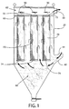
- a simplified illustration of a dust-collecting apparatus 10 is provided that includes a plurality of elongate filter elements 70.
- Fig. 1 shows a row of three filter elements 70
- embodiments of the present invention may have several rows each having 15 to 30 or more filter elements.
- the housing 20 of the dust-collecting apparatus 10 may have a transverse panel 60 dividing the housing into an inlet chamber 80 and an outlet chamber 82.
- the transverse panel 60 may define a plurality of openings 62 therein (shown in Fig. 2 ).
- the housing 20 may define an inlet extension 42 having an opening 44, and the dust-laden air may enter the inlet chamber 80 of the housing via the opening of the inlet extension.
- Each of the elongate filter elements 70 may have an open end 72 and a closed end 74, and the filter elements may be mounted to the transverse panel 60 such that the open ends are in registry with respective ones of the openings 62 in the panel.
- the filter elements 70 may extend into the inlet chamber 80, such that as the dust-laden air is passed through the filter elements, the dust is caught on an outside surface of the filter elements and clean air is moved up through the filter elements and into the outlet chamber 82 via the respective open ends 72 of the filter elements and the corresponding openings 62 of the transverse panel 60. The clean air may then be exhausted from the outlet chamber 82 via the outlet opening 50.
- a reverse pulse cleaning apparatus 90 may be provided that is configured for periodically directing a reverse pulse of air through each of the panel openings 62 and into the open ends 72 of the respective filter elements 70.
- the reverse pulse of air may serve to dislodge dust particles caught on the outer surface of the filter elements and allow the particles to fall to the bottom of the inlet chamber, where they may be collected and removed, thereby "cleaning" the filter elements 70 and allowing more dust to be captured by the respective filter elements.
- a reverse pulse cleaning apparatus is described, for example, in U.S. Patent No. 5,395,409 .
- housings 20 may need to be inspected and/or serviced by authorized personnel.
- the large size of some housings 20 (which may be upwards of 12m (40 feet) tall and approximately 3m (10 feet) deep by 6m (20 feet) wide or more), coupled with the difference in air temperature within the housing as compared to the external temperature due to normal operating conditions and the need to maintain an adequate seal on any access opening when not in use, however, may present additional challenges that are not addressed by conventional dust-collecting apparatuses.
- embodiments of the present invention provide for a dust-collecting apparatus that includes a door assembly designed to allow for safe access to be provided to the interior of the housing 20 and, at the same time, minimizes the adverse effects on the normal operation of the apparatus by allowing for a proper seal to be maintained between the interior and the exterior of the housing.
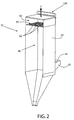
- the lift-off door assembly 100 may be disposed above the outlet chamber 82 of the housing 20 and may provide access to the outlet chamber when a lifting force F is applied to the lift-off door assembly to move the door assembly out of contact with the walls of the housing.
- the lift-off door assembly 100 may be configured to seal the outlet chamber 82 based on the weight of the door assembly (which may be in excess of 2722 kg (6000 pounds)) resting on the walls of the housing 20, rather than due to any physical attachment of the door assembly to the walls.
- the lift-off door assembly may be attached at one or more locations to corresponding portions of the housing, such as via a hinge or latch mechanism.
- the lift-off door assembly 100 may include a top plate 110, a door frame 120, and a bottom plate 130 that are configured to be lifted together to provide access to the interior of the housing via lift clips 140 (shown in Fig. 5 ), as described below.
- additional components may be attached to or otherwise supported by the lift-off door assembly 100, such as a header 150 and associated piping 155 for providing air at high pressures for cleaning of the filters 70 via the reverse pulse cleaning apparatus 90 shown in Fig. 1 and described above.
- a header 150 and associated piping 155 for providing air at high pressures for cleaning of the filters 70 via the reverse pulse cleaning apparatus 90 shown in Fig. 1 and described above.
- the header 150 may be supported on a top (exterior) face 112 of the top plate 110, and one or more sections of piping 155 may extend from the header, through the top and bottom plates 110, 130, and into the outlet chamber 82 for providing the reverse pulse of air through each of the panel openings 62 and into the open ends 72 of the respective filter elements 70.
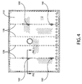
- Fig. 4 illustrates a top view of the lift-off door assembly 100 (e.g., from an exterior of the dust-collecting apparatus looking down at the top face 112 of the top plate 110 of the lift-off door assembly), and Fig. 5 illustrates a cross-sectional view of a portion of the lift-off door assembly 100.
- the top plate 110 may be disposed above the door frame 120 and may be attached to the door frame, such as via welding.
- the door frame 120 which is shown in Fig. 6 , may comprise two pairs of opposite side frame members 122, with adjacent side frame members being attached at their respective ends to form a perimeter portion of the door frame 120.
- each side frame member 122 may be a channel beam (shown in Figs. 5 and 5A ) that includes an upper portion 124, a lower portion 126, and a main portion 125 extending therebetween. Accordingly, in some embodiments, the upper portion 124 of each side frame member 122 may be attached to a corresponding face of the top plate 110, such as via welding, whereas the lower portion 126 may remain independent of the bottom plate 130, such that the bottom plate is free to move with respect to the side frame members 122 and the top plate, as described in greater detail below.
- the lift-off door assembly 100 may further include a plurality of interior frame members 128.
- the interior frame members 128 may be disposed substantially parallel to and between one of the two pairs of opposite side frame members 122.
- an end 129 of each interior frame member 128 may be attached to a respective side frame member 122 of the other of the two pairs of opposite side frame members (e.g., the side frame members that are oriented substantially perpendicularly to the interior side frame members), such as via welding.
- the door frame 120 may form a rigid framework for supporting the top plate 110 and distributing the weight of the top plate across the surface of the bottom plate 130.
- Each of the interior frame members 128 may be attached to a corresponding portion of the top plate 110, such as via welding. As noted above with respect to the side frame members 122, one or more of the interior frame members 128 may comprise channel beams, such as that shown in Fig. 5A .
- One or more of the top plate 110, bottom plate 130, and door frame 120 may be made of metal, such as steel.
- the top plate 110 and the bottom plate 130 may be connected in a central area of the respective plates, while leaving the outer regions of the respective plates independent from each other.
- an inspection hatch or other central structure may be provided that extends through and/or between the top plate 110, the door frame 120, and the bottom frame 130, which may assist in transferring a lifting force applied to the top plate to the bottom plate while allowing the outer edge of the bottom plate to move (e.g., expand and contract) with respect to the side frame members and the top plate, as described in greater detail below.
- Fig. 7 illustrates a bottom view of the lift-off door assembly 100 (e.g., from an interior of the dust-collecting apparatus looking up at the bottom plate 130 of the lift-off door assembly.
- a plurality of lift clips 140 may thus be provided for facilitating the transfer of a lifting force F applied to the top plate 110 (shown in Fig. 2 ) to the bottom plate 130.
- the lift clips 140 may also be made of steel or other metal in some embodiments.
- the lift clips 140 may be disposed at locations 141 around a perimeter of the bottom plate 130 and may be attached to the bottom plate, such as via welding.
- a portion of the door frame 120 may be configured to engage the lift clips 140 when the top plate 110 is subjected to a lifting force F such that the lifting force causes the lift-off door assembly 100, including the bottom plate 130, to be lifted together to move the lift-off door assembly from the closed position (in which the door assembly is in contact with the housing) to an open position (in which the door assembly is at least partially separated from the housing and provides access to the interior of the housing).
- a lifting force F such that the lifting force causes the lift-off door assembly 100, including the bottom plate 130, to be lifted together to move the lift-off door assembly from the closed position (in which the door assembly is in contact with the housing) to an open position (in which the door assembly is at least partially separated from the housing and provides access to the interior of the housing).
- the locations 141 of the lift clips 140 are arranged such that the lift clips are distributed substantially equally around the perimeter of the bottom plate 130.
- each lift clip may extend upward (e.g., toward the top plate 110) and inward (e.g., toward a center of the lift-off door assembly 100), such that a portion of each lift clip is positioned over an outer portion of the door frame 120.
- the outer portion of the door frame 120 may be configured to engage the lift clips 140 when the top plate 110 is subjected to the lifting force described above.
- the door frame includes side frame members 122 comprising channel beams, as shown in Figs.
- each lift clip 140 may include a lifting end 142 that is spaced from the lower portion 126 of the corresponding side frame member 122 when the lift-off door assembly 100 is in the closed position and the top plate 110 and door frame 120 are resting against the bottom plate 130 due to the force of gravity ( Fig. 5A ).
- the top plate 110 is subjected to the lifting force (e.g., via lifting lugs 160 shown in Figs. 4 and 5 )
- the door frame 120 by virtue of its attachment to the top plate 110, is caused to move away from the bottom plate 130 by a distance d until the lower portion 126 of the side frame member 122 makes contact with the lifting end 142 of the respective lift clip 140 ( Fig. 5B ).
- the engagement of the lift clip 140 with the door frame 120 serves to lift the bottom plate 130 along with the top plate 110 and the door frame 120 as the lifting force continues to be applied to the top plate to move the entire lift-off door assembly 100 up and away from the housing of the dust-collecting apparatus.
- the lift-off door assembly 100 By providing lift clips 140 to transfer the lifting force F (shown in Fig. 2 ) from the top plate 110 to the bottom plate 130 via the door frame 120, it is possible to move the lift-off door assembly 100 as a unit between the closed position and the open position for providing access to the interior of the housing of the dust-collecting assembly 10 without necessitating that the bottom plate be attached to the door frame or the top plate at least at a perimeter region of the bottom plate. In this way, the outer edge of the bottom plate 130 is allowed to expand and contract relative to the top plate 110, for example as a result of differences in temperature between the interior of the housing of the dust-collecting apparatus and the exterior (e.g., ambient) environment.
- the exterior e.g., ambient
- the dust-collecting apparatus may further comprise a strengthening bar 170 that is attached (e.g., via welding) to an outer edge 131 of the bottom plate 130 and is configured to resist curling or other distortion of the outer edge, as shown in Fig. 5 .
- the strengthening bar 170 may, for example, be attached substantially perpendicularly to the bottom plate 130, as shown.
- the strengthening bar 170 may be attached, for example, around at least a portion of the outer edge 131 of the bottom plate 130, or, in some cases, may be extended about an entire perimeter of the outer edge, such that the strengthening bar forms a lip or rim around the outer edge.
- the strengthening bar 170 may thus add rigidity to the outer edge 131 of the bottom plate 130, such that curling or other distortion of the outer edge (e.g., due to thermal expansion and contraction) may be resisted.
- the lift-off door assembly comprises a single bottom plate, door frame, and top plate
- the lift-off door assembly comprises two or more lift-off door portions, where each lift-off door portion comprises a bottom plate, a door frame, and a top plate.
- a first portion of the lift-off door may be embodied as described and shown with respect to Fig. 3
- a second portion of the lift-off door may be embodied as described with respect to Fig. 3 , but without the header 150 or the piping 155.
- the two portions may be configured to form a seal along respective adjacent edges, such that in the closed position the outlet chamber of the housing is enclosed and sealed via the two lift-off door portions.
- the lift-off door portions may, in some cases, be configured to move from the closed position to the open position independently from each other.
Landscapes
- Chemical & Material Sciences (AREA)
- Chemical Kinetics & Catalysis (AREA)
- Physics & Mathematics (AREA)
- Thermal Sciences (AREA)
- Geometry (AREA)
- Filtering Of Dispersed Particles In Gases (AREA)
- Auxiliary Methods And Devices For Loading And Unloading (AREA)
Description
- The present invention relates generally to systems and apparatuses for collecting dust using a dust-collecting housing, as well as systems and apparatuses for accessing an interior of the housing.
- Conventional self-cleaning dust collectors of the described type typically comprise a sheet metal housing that is divided by a transverse panel having a plurality of rows of openings therein, and so that the panel defines a lower air inlet chamber and an upper air outlet chamber. Cylindrical filter elements, such as fabric filter bags or cartridge filters, are mounted so as to be in registry with the openings and depend downwardly into the inlet chamber. In operation, the dust-laden air enters the inlet chamber, the entrained particles are deposited on the outside surfaces of the filter bags, and the filtered air flows upwardly through the inside of the bags and is discharged through the upper outlet chamber.
- Such dust-collecting apparatuses are typically installed at industrial and manufacturing facilities where there is a need to remove dust and other contaminants from the air. Facilities where dust collection is typically required include power and steam generation sites, cement manufacturing sites, iron and steel mills, mining facilities, chemical and petro-chemical facilities, and glass manufacturing sites, among others. From time to time, access to the interior of the dust-collecting apparatus may be required, such as to perform inspections and maintenance.
- Accordingly, there is a need in the art for systems and apparatuses that can provide access to the interior of a dust-collecting apparatus in a simple and cost-effective manner without adversely affecting the operation of the apparatus.
- Accordingly, embodiments of systems and apparatuses for dust-collecting are described that include a door assembly designed to allow for safe access to be provided to the interior of a dust-collecting housing and, at the same time, minimize the adverse effects on the normal operation of the dust-collecting apparatus by allowing for a proper seal to be maintained between the interior and the exterior of the housing. In some embodiments, a dust-collecting apparatus is provided that includes a housing having a transverse panel dividing the housing into an inlet chamber and an outlet chamber, with the panel having a plurality of openings therein, and a plurality of elongate filter elements each having an open end and a closed end, with the filter elements being mounted to the panel such that the open ends are in registry with respective ones of the openings in the panel and the filter elements extend into the inlet chamber. The apparatus may further include a reverse pulse cleaning apparatus configured for periodically directing a reverse pulse of air through each of the panel openings and into the open ends of each of the filter elements and may also include a lift-off door assembly disposed above the outlet chamber of the housing.
- The lift-off door assembly may comprise a top plate, a door frame, a bottom plate, and a plurality of lift clips. The top plate may be disposed above the door frame and may be attached thereto. The bottom plate may be disposed below the door frame, and the lift clips may be disposed around a perimeter of the bottom plate and may be attached thereto. A portion of the door frame may be configured to engage the lift clips when the top plate is subjected to a lifting force such that the lifting force causes the lift-off door assembly, including the bottom plate, to be lifted together.
- In some cases, the door frame may comprise two pairs of opposite side frame members, and adjacent side frame members may be attached at their respective ends. The side frame members may comprise channel beams. The door frame may further comprise a plurality of interior frame members disposed substantially parallel to and between one of the two pairs of opposite side frame members, and an end of each interior frame member may be attached to a respective side frame member of the other of the two pairs of opposite side frame members.
- The lift clips may, in some cases, be distributed substantially equally around the perimeter of the bottom plate. Furthermore, each lift clip may extend upward and inward such that a lifting end of each lift clip is positioned over an outer portion of the door frame, and the outer portion of the door frame may be configured to engage the lift clips when the top plate is subjected to the lifting force. In some cases, a strengthening bar may be attached to an outer edge of the bottom plate and may be configured to resist curling thereof.
- In other embodiments, a lift-off door assembly may be provided for use in a dust-collecting apparatus. The lift-off door assembly may comprise a top plate, a door frame, a bottom plate, and a plurality of lift clips. The top plate may be disposed above the door frame and may be attached thereto. The bottom plate may be disposed below the door frame, and the lift clips may be disposed around a perimeter of the bottom plate and may be attached thereto. A portion of the door frame may be configured to engage the lift clips when the top plate is subjected to a lifting force such that the lifting force causes the lift-off door assembly, including the bottom plate, to be lifted together.
- In some cases, the door frame may comprise two pairs of opposite side frame members. The side frame members may comprise channel beams. The door frame may further comprise a plurality of interior frame members disposed substantially parallel to and between one of the two pairs of opposite side frame members.
- The lift clips may be distributed substantially equally around the perimeter of the bottom plate. Each lift clip may extend upward and inward such that a lifting end of each lift clip is positioned over an outer portion of the door frame, and the outer portion of the door frame may be configured to engage the lift clips when the top plate is subjected to the lifting force. A strengthening bar may, in some cases, be attached to an outer edge of the bottom plate and may be configured to resist curling thereof.
- Having thus described the invention in general terms, reference will now be made to the accompanying drawings, which are not necessarily drawn to scale, and wherein:
-
FIG. 1 shows a simplified schematic representation of a cross-section of a dust-collecting apparatus including elongate filter elements in accordance with an exemplary embodiment of the present invention; -
FIG. 2 shows a simplified perspective view of the interior of a dust-collecting apparatus in accordance with an exemplary embodiment of the present invention; -
FIG. 3 shows a perspective view of a lift-off door assembly in accordance with an exemplary embodiment of the present invention, with the lift clips removed; -
FIG. 4 shows a top view of the lift-off door assembly from an exterior of the dust-collecting apparatus looking down at the top face of a top plate of the lift-off door assembly in accordance with an exemplary embodiment of the present invention; -
FIG. 5 shows a cross-sectional view of a portion of the lift-off door assembly ofFig. 4 in accordance with an exemplary embodiment of the present invention; -
FIG. 5A shows a close-up cross-sectional view of a lift clip and a side frame member ofFig. 5 when the lift-off door assembly is in a closed position in accordance with an exemplary embodiment of the present invention; -
FIG. 5B shows a close-up cross-sectional view of the lift clip and the side frame member ofFig. 5A when the lift-off door assembly is in an open position in accordance with an exemplary embodiment of the present invention; -
FIG. 6 shows a top view of a door frame of the lift-off door assembly in accordance with an exemplary embodiment of the present invention; and -
FIG. 7 shows a bottom view of the lift-off door assembly ofFig. 5 from an interior of the dust-collecting apparatus looking up at the bottom plate of the lift-off door assembly in accordance with an exemplary embodiment of the present invention. - Some embodiments of the present invention will now be described more fully hereinafter with reference to the accompanying drawings, in which some, but not all, embodiments of the invention are shown. Indeed, various embodiments of the invention may be embodied in many different forms and should not be construed as limited to the embodiments set forth herein; rather, these embodiments are provided so that this disclosure will satisfy applicable legal requirements. Like reference numerals refer to like elements throughout. Some components of the dust-collecting apparatus and associated systems are not shown in one or more of the figures for clarity and to facilitate explanation of embodiments of the present invention.
- As used herein, the terms "bottom," "top," "upper," "lower," "inner," "outer," and similar terms are used for ease of explanation and refer generally to the position of certain components of embodiments of the described invention in the installed configuration (e.g., in an operational configuration). It is understood that such terms are not used in any absolute sense, and, as such, a component described as a "lower portion" may be on the same level (e.g., at the same distance from the ground) as another component described as an "upper portion" in certain configurations of embodiments of the described invention, such as when the apparatus is being transported to the installation site or is not yet fully assembled or installed. Moreover, in the description and examples provided herein, the term "dust" is used to refer to any particulates or contaminants in the air or any other gas stream that are capable of being removed to some degree via mechanical or physical separation, such as by using one or more filters.
- Conventional dust-collecting apparatuses are structures that hold one or more filters. On a very basic level, these structures are arranged such that dust-laden air may be directed into one end of the apparatus and moved through the filters where the dust (or some percentage of the dust) is removed. The cleaned air may then be exhausted from another end of the structure, for example, for safe release into the environment.
- With reference to
Fig. 1 , for example, a simplified illustration of a dust-collectingapparatus 10 is provided that includes a plurality ofelongate filter elements 70. AlthoughFig. 1 shows a row of threefilter elements 70, embodiments of the present invention may have several rows each having 15 to 30 or more filter elements. Thehousing 20 of the dust-collectingapparatus 10 may have atransverse panel 60 dividing the housing into aninlet chamber 80 and anoutlet chamber 82. Thetransverse panel 60 may define a plurality ofopenings 62 therein (shown inFig. 2 ). In some cases, thehousing 20 may define aninlet extension 42 having anopening 44, and the dust-laden air may enter theinlet chamber 80 of the housing via the opening of the inlet extension. - Each of the
elongate filter elements 70 may have anopen end 72 and aclosed end 74, and the filter elements may be mounted to thetransverse panel 60 such that the open ends are in registry with respective ones of theopenings 62 in the panel. Thefilter elements 70 may extend into theinlet chamber 80, such that as the dust-laden air is passed through the filter elements, the dust is caught on an outside surface of the filter elements and clean air is moved up through the filter elements and into theoutlet chamber 82 via the respective open ends 72 of the filter elements and the correspondingopenings 62 of thetransverse panel 60. The clean air may then be exhausted from theoutlet chamber 82 via theoutlet opening 50. - In some cases, a reverse
pulse cleaning apparatus 90 may be provided that is configured for periodically directing a reverse pulse of air through each of thepanel openings 62 and into the open ends 72 of therespective filter elements 70. The reverse pulse of air may serve to dislodge dust particles caught on the outer surface of the filter elements and allow the particles to fall to the bottom of the inlet chamber, where they may be collected and removed, thereby "cleaning" thefilter elements 70 and allowing more dust to be captured by the respective filter elements. A reverse pulse cleaning apparatus is described, for example, inU.S. Patent No. 5,395,409 . - To maintain the proper operation of the dust-collecting
apparatus 10, such as to ensure that a sufficient volume and rate of airflow is processed by the apparatus and that dust is removed from the air to an acceptable level, certain components located within thehousing 20 may need to be inspected and/or serviced by authorized personnel. The large size of some housings 20 (which may be upwards of 12m (40 feet) tall and approximately 3m (10 feet) deep by 6m (20 feet) wide or more), coupled with the difference in air temperature within the housing as compared to the external temperature due to normal operating conditions and the need to maintain an adequate seal on any access opening when not in use, however, may present additional challenges that are not addressed by conventional dust-collecting apparatuses. - Accordingly, embodiments of the present invention provide for a dust-collecting apparatus that includes a door assembly designed to allow for safe access to be provided to the interior of the
housing 20 and, at the same time, minimizes the adverse effects on the normal operation of the apparatus by allowing for a proper seal to be maintained between the interior and the exterior of the housing. - Referring now to
Figs. 2 and3 , a simplified view of a lift-offdoor assembly 100 in accordance with embodiments of the present invention is shown, with some of the components removed for purposes of explanation. In general, the lift-offdoor assembly 100 may be disposed above theoutlet chamber 82 of thehousing 20 and may provide access to the outlet chamber when a lifting force F is applied to the lift-off door assembly to move the door assembly out of contact with the walls of the housing. For example, in some embodiments, the lift-offdoor assembly 100 may be configured to seal theoutlet chamber 82 based on the weight of the door assembly (which may be in excess of 2722 kg (6000 pounds)) resting on the walls of thehousing 20, rather than due to any physical attachment of the door assembly to the walls. In other embodiments, however, the lift-off door assembly may be attached at one or more locations to corresponding portions of the housing, such as via a hinge or latch mechanism. - With reference to
Fig. 3 , the lift-offdoor assembly 100 may include atop plate 110, adoor frame 120, and abottom plate 130 that are configured to be lifted together to provide access to the interior of the housing via lift clips 140 (shown inFig. 5 ), as described below. In some cases, additional components may be attached to or otherwise supported by the lift-offdoor assembly 100, such as aheader 150 and associated piping 155 for providing air at high pressures for cleaning of thefilters 70 via the reversepulse cleaning apparatus 90 shown inFig. 1 and described above. For example, as shown inFig. 3 , theheader 150 may be supported on a top (exterior) face 112 of thetop plate 110, and one or more sections of piping 155 may extend from the header, through the top andbottom plates outlet chamber 82 for providing the reverse pulse of air through each of thepanel openings 62 and into the open ends 72 of therespective filter elements 70. -
Fig. 4 illustrates a top view of the lift-off door assembly 100 (e.g., from an exterior of the dust-collecting apparatus looking down at thetop face 112 of thetop plate 110 of the lift-off door assembly), andFig. 5 illustrates a cross-sectional view of a portion of the lift-offdoor assembly 100. With reference toFigs. 4 and5 , thetop plate 110 may be disposed above thedoor frame 120 and may be attached to the door frame, such as via welding. In this regard, thedoor frame 120, which is shown inFig. 6 , may comprise two pairs of oppositeside frame members 122, with adjacent side frame members being attached at their respective ends to form a perimeter portion of thedoor frame 120. In the depicted embodiment, eachside frame member 122 may be a channel beam (shown inFigs. 5 and 5A ) that includes anupper portion 124, alower portion 126, and amain portion 125 extending therebetween. Accordingly, in some embodiments, theupper portion 124 of eachside frame member 122 may be attached to a corresponding face of thetop plate 110, such as via welding, whereas thelower portion 126 may remain independent of thebottom plate 130, such that the bottom plate is free to move with respect to theside frame members 122 and the top plate, as described in greater detail below. - In some cases, the lift-off
door assembly 100 may further include a plurality ofinterior frame members 128. In the depicted embodiment, for example, fourinterior frame members 128 are provided; however, the number of interior frame members may vary based on the particular configuration of the lift-off door assembly (e.g., the size and weight of the door assembly), among other considerations. Theinterior frame members 128 may be disposed substantially parallel to and between one of the two pairs of oppositeside frame members 122. In some embodiments, anend 129 of eachinterior frame member 128 may be attached to a respectiveside frame member 122 of the other of the two pairs of opposite side frame members (e.g., the side frame members that are oriented substantially perpendicularly to the interior side frame members), such as via welding. In this way, thedoor frame 120 may form a rigid framework for supporting thetop plate 110 and distributing the weight of the top plate across the surface of thebottom plate 130. - Each of the
interior frame members 128 may be attached to a corresponding portion of thetop plate 110, such as via welding. As noted above with respect to theside frame members 122, one or more of theinterior frame members 128 may comprise channel beams, such as that shown inFig. 5A . One or more of thetop plate 110,bottom plate 130, anddoor frame 120 may be made of metal, such as steel. - In some embodiments, the
top plate 110 and thebottom plate 130 may be connected in a central area of the respective plates, while leaving the outer regions of the respective plates independent from each other. For example, an inspection hatch or other central structure may be provided that extends through and/or between thetop plate 110, thedoor frame 120, and thebottom frame 130, which may assist in transferring a lifting force applied to the top plate to the bottom plate while allowing the outer edge of the bottom plate to move (e.g., expand and contract) with respect to the side frame members and the top plate, as described in greater detail below. -
Fig. 7 illustrates a bottom view of the lift-off door assembly 100 (e.g., from an interior of the dust-collecting apparatus looking up at thebottom plate 130 of the lift-off door assembly. Referring toFigs. 5 and7 , a plurality of lift clips 140 may thus be provided for facilitating the transfer of a lifting force F applied to the top plate 110 (shown inFig. 2 ) to thebottom plate 130. The lift clips 140 may also be made of steel or other metal in some embodiments. The lift clips 140 may be disposed atlocations 141 around a perimeter of thebottom plate 130 and may be attached to the bottom plate, such as via welding. A portion of thedoor frame 120 may be configured to engage the lift clips 140 when thetop plate 110 is subjected to a lifting force F such that the lifting force causes the lift-offdoor assembly 100, including thebottom plate 130, to be lifted together to move the lift-off door assembly from the closed position (in which the door assembly is in contact with the housing) to an open position (in which the door assembly is at least partially separated from the housing and provides access to the interior of the housing). For example, in the embodiment depicted inFig. 7 , thelocations 141 of the lift clips 140 are arranged such that the lift clips are distributed substantially equally around the perimeter of thebottom plate 130. - Turning again to
Fig. 5 , in some embodiments, each lift clip may extend upward (e.g., toward the top plate 110) and inward (e.g., toward a center of the lift-off door assembly 100), such that a portion of each lift clip is positioned over an outer portion of thedoor frame 120. In this way, the outer portion of thedoor frame 120 may be configured to engage the lift clips 140 when thetop plate 110 is subjected to the lifting force described above. For example, in the depicted embodiment in which the door frame includesside frame members 122 comprising channel beams, as shown inFigs. 5A and 5B , eachlift clip 140 may include a liftingend 142 that is spaced from thelower portion 126 of the correspondingside frame member 122 when the lift-offdoor assembly 100 is in the closed position and thetop plate 110 anddoor frame 120 are resting against thebottom plate 130 due to the force of gravity (Fig. 5A ). When thetop plate 110 is subjected to the lifting force (e.g., via liftinglugs 160 shown inFigs. 4 and5 ), however, thedoor frame 120, by virtue of its attachment to thetop plate 110, is caused to move away from thebottom plate 130 by a distance d until thelower portion 126 of theside frame member 122 makes contact with the liftingend 142 of the respective lift clip 140 (Fig. 5B ). Accordingly, the engagement of thelift clip 140 with the door frame 120 (e.g., via theside frame members 122 as described above) serves to lift thebottom plate 130 along with thetop plate 110 and thedoor frame 120 as the lifting force continues to be applied to the top plate to move the entire lift-offdoor assembly 100 up and away from the housing of the dust-collecting apparatus. - By providing
lift clips 140 to transfer the lifting force F (shown inFig. 2 ) from thetop plate 110 to thebottom plate 130 via thedoor frame 120, it is possible to move the lift-offdoor assembly 100 as a unit between the closed position and the open position for providing access to the interior of the housing of the dust-collectingassembly 10 without necessitating that the bottom plate be attached to the door frame or the top plate at least at a perimeter region of the bottom plate. In this way, the outer edge of thebottom plate 130 is allowed to expand and contract relative to thetop plate 110, for example as a result of differences in temperature between the interior of the housing of the dust-collecting apparatus and the exterior (e.g., ambient) environment. In contrast, conventional door assemblies that do not allow for independent movement as between a portion of the door that is exposed to the operating environment within the housing and a portion of the door that is exposed to the external environment may experience warping or other distortion around the perimeter of the door, which may adversely affect the seal that is applied by the door to the outlet chamber and, as a result, may adversely affect the performance of the dust-collecting apparatus. - In this regard, in some embodiments, the dust-collecting apparatus may further comprise a strengthening
bar 170 that is attached (e.g., via welding) to anouter edge 131 of thebottom plate 130 and is configured to resist curling or other distortion of the outer edge, as shown inFig. 5 . The strengtheningbar 170 may, for example, be attached substantially perpendicularly to thebottom plate 130, as shown. The strengtheningbar 170 may be attached, for example, around at least a portion of theouter edge 131 of thebottom plate 130, or, in some cases, may be extended about an entire perimeter of the outer edge, such that the strengthening bar forms a lip or rim around the outer edge. The strengtheningbar 170 may thus add rigidity to theouter edge 131 of thebottom plate 130, such that curling or other distortion of the outer edge (e.g., due to thermal expansion and contraction) may be resisted. - Although in the depicted embodiment and the examples provided above the lift-off door assembly comprises a single bottom plate, door frame, and top plate, in some embodiments the lift-off door assembly comprises two or more lift-off door portions, where each lift-off door portion comprises a bottom plate, a door frame, and a top plate. For example, a first portion of the lift-off door may be embodied as described and shown with respect to
Fig. 3 , and a second portion of the lift-off door may be embodied as described with respect toFig. 3 , but without theheader 150 or thepiping 155. The two portions may be configured to form a seal along respective adjacent edges, such that in the closed position the outlet chamber of the housing is enclosed and sealed via the two lift-off door portions. The lift-off door portions may, in some cases, be configured to move from the closed position to the open position independently from each other. - As noted above, the structures and components depicted in the figures have been simplified for clarity and ease of explanation. As such, one or more of the housing walls, internal and/or external ductwork, filter elements, etc., although described above, may not be shown in the figures. In addition, many modifications and other embodiments of the invention will come to mind to one skilled in the art to which this invention pertains having the benefit of the teachings presented in the foregoing descriptions and the associated drawings. Therefore, it is to be understood that the invention is not to be limited to the specific embodiments disclosed and that modifications and other embodiments are intended to be included within the scope of the appended claims. Although specific terms are employed herein, they are used in a generic and descriptive sense only and not for purposes of limitation.
Claims (14)
- A dust-collecting apparatus (10) comprising:a housing (20) having a transverse panel (60) dividing the housing into an inlet chamber (80) and an outlet chamber (82), with the panel having a plurality of openings (62) therein;a plurality of elongate filter elements (70) each having an open end (72) and a closed end (74), with the filter elements being mounted to the panel (60) such that the open ends are in registry with respective ones of the openings (62) in the panel and the filter elements (70) extend into the inlet chamber (80);a reverse pulse cleaning apparatus (90) configured for periodically directing a reverse pulse of air through each of the panel openings (62) and into the open ends (72) of each of the filter elements (70);characterised in that the dust-collecting apparatus further comprisesa lift-off door assembly (100) disposed above the outlet chamber (82) of the housing (20), the lift-off door assembly (100) comprising a top plate (110), a doorframe (120), a bottom plate (130), and a plurality of lift clips (140),wherein the top plate (110) is disposed above the door frame (120) and is attached thereto, the bottom plate (130) is disposed below the door frame (120), and the lift clips (140) are disposed around a perimeter of the bottom plate (130) and are attached thereto, and wherein a portion of the door frame (120) is configured to engage the lift clips (140) when the top plate (110) is subjected to a lifting force such that the lifting force causes the lift-off door assembly (100), including the bottom plate (130), to be lifted together.
- The dust-collecting apparatus of Claim 1, wherein the door frame (120) comprises two pairs of opposite side frame members (122), wherein adjacent side frame members are attached at their respective ends.
- The dust-collecting apparatus of Claim 2, wherein the side frame members (122) comprise channel beams.
- The dust-collecting apparatus of Claim 2, wherein the door frame (120) further comprises a plurality of interior frame members (128) disposed substantially parallel to and between one of the two pairs of opposite side frame members (122), wherein an end (129) of each interior frame member (128) is attached to a respective side frame member (122) of the other of the two pairs of opposite side frame members (122).
- The dust-collecting apparatus of Claim 1, wherein the lift clips (140) are distributed substantially equally around the perimeter of the bottom plate (130).
- The dust-collecting apparatus of Claim 1, wherein each lift clip (140) extends upward and inward such that a lifting end (142) of each lift clip is positioned over an outer portion of the door frame (120), and wherein the outer portion of the door frame (120) is configured to engage the lift clips (140) when the top plate (110) is subjected to the lifting force.
- The dust-collecting apparatus of Claim 1, further comprising a strengthening bar (170) attached to an outer edge (131) of the bottom plate (130) and configured to resist curling thereof.
- A lift-off door assembly (100) for use in a dust-collecting apparatus (10), said assembly comprising:a top plate (110), a door frame (120), and a bottom plate (130),characterised in that the lift-off door assembly further comprises a plurality of lift clips (140),and wherein the top plate (110) is disposed above the door frame (120) and is attached thereto, the bottom plate (130) is disposed below the door frame (120), and the lift clips (140) are disposed around a perimeter of the bottom plate (130) and are attached thereto, and wherein a portion of the door frame (120) is configured to engage the lift clips (140) when the top plate (110) is subjected to a lifting force such that the lifting force causes the lift-off door assembly (100), including the bottom plate (130), to be lifted together.
- The lift-off door assembly of Claim 8, wherein the door frame (120) comprises two pairs of opposite side frame members (122).
- The lift-off door assembly of Claim 9, wherein the side frame members (122) comprise channel beams.
- The lift-off door assembly of Claim 9, wherein the door frame (120) further comprises a plurality of interior frame members (128) disposed substantially parallel to and between one of the two pairs of opposite side frame members (122).
- The lift-off door assembly of Claim 8, wherein the lift clips (140) are distributed substantially equally around the perimeter of the bottom plate (130).
- The lift-off door assembly of Claim 8, wherein each lift clip (140) extends upward and inward such that a lifting end (142) of each lift clip (140) is positioned over an outer portion of the door frame (120), and wherein the outer portion of the door frame (120) is configured to engage the lift clips (140) when the top plate (110) is subjected to the lifting force.
- The lift-off door assembly of Claim 8, further comprising a strengthening bar (170) attached to an outer edge of the bottom plate (130) and configured to resist curling thereof.
Applications Claiming Priority (2)
| Application Number | Priority Date | Filing Date | Title |
|---|---|---|---|
| US13/408,677 US8961638B2 (en) | 2012-02-29 | 2012-02-29 | Door assembly for dust-collecting apparatus |
| PCT/US2013/028241 WO2013130751A1 (en) | 2012-02-29 | 2013-02-28 | Door assembly for dust-collecting apparatus |
Publications (2)
| Publication Number | Publication Date |
|---|---|
| EP2819762A1 EP2819762A1 (en) | 2015-01-07 |
| EP2819762B1 true EP2819762B1 (en) | 2016-05-25 |
Family
ID=47901362
Family Applications (1)
| Application Number | Title | Priority Date | Filing Date |
|---|---|---|---|
| EP13710685.2A Not-in-force EP2819762B1 (en) | 2012-02-29 | 2013-02-28 | Door assembly for dust-collecting apparatus |
Country Status (7)
| Country | Link |
|---|---|
| US (1) | US8961638B2 (en) |
| EP (1) | EP2819762B1 (en) |
| CL (1) | CL2014002311A1 (en) |
| CO (1) | CO7141453A2 (en) |
| HK (1) | HK1205042A1 (en) |
| PE (1) | PE20142230A1 (en) |
| WO (1) | WO2013130751A1 (en) |
Family Cites Families (13)
| Publication number | Priority date | Publication date | Assignee | Title |
|---|---|---|---|---|
| US2661811A (en) | 1951-12-29 | 1953-12-08 | Kautz Karl | Apparatus for continuously filtering solids from gases |
| DE1197736B (en) | 1955-12-01 | 1965-07-29 | Waldemar Harnisch | Dust separator for air and gases, especially for pressurized gas lines, with hanging stiff filter candles and knocking device |
| US3726066A (en) | 1970-12-14 | 1973-04-10 | Wheelabrator Frye Inc | Dust collector |
| US3839850A (en) | 1972-01-03 | 1974-10-08 | Envirotech Corp | Enclosure assembly |
| US3951627A (en) | 1975-01-09 | 1976-04-20 | Pneumafil Corporation | Air filtering apparatus |
| US4955996A (en) | 1989-05-23 | 1990-09-11 | Dustex Corporation | Top loading dust collector |
| US5062867A (en) | 1989-12-14 | 1991-11-05 | Dustex Corporation | Method of retrofitting a dust collecting apparatus |
| US4976756A (en) | 1990-01-16 | 1990-12-11 | Atlantic Richfield Company | Dust collector housing with removable roof section |
| US5222276A (en) * | 1992-01-10 | 1993-06-29 | Ryobi Motor Products Corp. | Vacuum cleaner for on floor and off floor suction cleaning |
| US5421846A (en) | 1993-08-25 | 1995-06-06 | Dustex Corporation | Air filtration apparatus for the control of industrial air pollution |
| US5395409A (en) * | 1994-02-03 | 1995-03-07 | Dustex Corporation | Dust collecting apparatus having reverse pulse filter cleaning capability |
| SE507239C2 (en) | 1996-01-23 | 1998-04-27 | Flaekt Ab | Device for cleaning filter elements |
| US7806948B2 (en) | 2006-11-14 | 2010-10-05 | Johnson Crushers International | Filter system for internal combustion engines operated in a contaminated atmosphere |
-
2012
- 2012-02-29 US US13/408,677 patent/US8961638B2/en active Active
-
2013
- 2013-02-28 HK HK15105610.2A patent/HK1205042A1/en unknown
- 2013-02-28 WO PCT/US2013/028241 patent/WO2013130751A1/en not_active Ceased
- 2013-02-28 PE PE2014001338A patent/PE20142230A1/en not_active Application Discontinuation
- 2013-02-28 EP EP13710685.2A patent/EP2819762B1/en not_active Not-in-force
-
2014
- 2014-08-29 CL CL2014002311A patent/CL2014002311A1/en unknown
- 2014-09-05 CO CO14196543A patent/CO7141453A2/en unknown
Also Published As
| Publication number | Publication date |
|---|---|
| CO7141453A2 (en) | 2014-12-12 |
| US20130220132A1 (en) | 2013-08-29 |
| US8961638B2 (en) | 2015-02-24 |
| HK1205042A1 (en) | 2015-12-11 |
| PE20142230A1 (en) | 2015-01-15 |
| EP2819762A1 (en) | 2015-01-07 |
| WO2013130751A1 (en) | 2013-09-06 |
| CL2014002311A1 (en) | 2015-04-17 |
Similar Documents
| Publication | Publication Date | Title |
|---|---|---|
| US4395269A (en) | Compact dust filter assembly | |
| US4158554A (en) | Apparatus for filtering particulate-laden gases | |
| CN112108300B (en) | Paint mist removal device and painting equipment | |
| US6364921B1 (en) | Air filter assembly for filtering air having particulate matter | |
| US10556198B2 (en) | Filter systems with dirty air chamber spacer elements and methods of using the same | |
| JP6414719B2 (en) | Convective dry containment filter vent system | |
| EP1313542B1 (en) | A filter construction apparatus and method | |
| KR20160143841A (en) | An intake filter device, a filter exchange method of an intake filter device, and a gas turbine | |
| US10994163B2 (en) | Kitchen ventilation system | |
| EP4149653A1 (en) | Air filtering apparatus | |
| US20240082769A1 (en) | Cartridges for Vertically Oriented Dust Collectors | |
| US4309200A (en) | Baghouse with collapsible bag filter assembly | |
| CN105327585B (en) | A kind of integrated separator device and dust removal method | |
| EP1299171B1 (en) | Air filter assembly for filtering air having particulate matter | |
| US8961638B2 (en) | Door assembly for dust-collecting apparatus | |
| CN201085970Y (en) | Back flushing cloth bag dust-collecting equipment | |
| US3372534A (en) | Baghouse construction | |
| EP2030666B1 (en) | Bag-filter filtering unit with replaceable filtering modules for combustion plants | |
| KR100913703B1 (en) | Oily Dust Smoke Collector | |
| KR20190100587A (en) | Compressed air filtering apparatus and filtering method using the same as | |
| JP3597713B2 (en) | Gas filter device | |
| JP3460645B2 (en) | Dust collector and its maintenance method | |
| JPH05345109A (en) | High temperature gas filtering apparatus | |
| KR102786963B1 (en) | Vertical assembly type electric dust collector for easy maintenance and repair | |
| JP2000237518A (en) | Gas filter device |
Legal Events
| Date | Code | Title | Description |
|---|---|---|---|
| PUAI | Public reference made under article 153(3) epc to a published international application that has entered the european phase |
Free format text: ORIGINAL CODE: 0009012 |
|
| 17P | Request for examination filed |
Effective date: 20140917 |
|
| AK | Designated contracting states |
Kind code of ref document: A1 Designated state(s): AL AT BE BG CH CY CZ DE DK EE ES FI FR GB GR HR HU IE IS IT LI LT LU LV MC MK MT NL NO PL PT RO RS SE SI SK SM TR |
|
| AX | Request for extension of the european patent |
Extension state: BA ME |
|
| DAX | Request for extension of the european patent (deleted) | ||
| 17Q | First examination report despatched |
Effective date: 20150729 |
|
| REG | Reference to a national code |
Ref country code: HK Ref legal event code: DE Ref document number: 1205042 Country of ref document: HK |
|
| GRAP | Despatch of communication of intention to grant a patent |
Free format text: ORIGINAL CODE: EPIDOSNIGR1 |
|
| INTG | Intention to grant announced |
Effective date: 20151217 |
|
| GRAS | Grant fee paid |
Free format text: ORIGINAL CODE: EPIDOSNIGR3 |
|
| GRAA | (expected) grant |
Free format text: ORIGINAL CODE: 0009210 |
|
| AK | Designated contracting states |
Kind code of ref document: B1 Designated state(s): AL AT BE BG CH CY CZ DE DK EE ES FI FR GB GR HR HU IE IS IT LI LT LU LV MC MK MT NL NO PL PT RO RS SE SI SK SM TR |
|
| REG | Reference to a national code |
Ref country code: GB Ref legal event code: FG4D |
|
| REG | Reference to a national code |
Ref country code: CH Ref legal event code: EP |
|
| REG | Reference to a national code |
Ref country code: AT Ref legal event code: REF Ref document number: 801775 Country of ref document: AT Kind code of ref document: T Effective date: 20160615 Ref country code: IE Ref legal event code: FG4D |
|
| REG | Reference to a national code |
Ref country code: DE Ref legal event code: R096 Ref document number: 602013007932 Country of ref document: DE |
|
| REG | Reference to a national code |
Ref country code: LT Ref legal event code: MG4D |
|
| REG | Reference to a national code |
Ref country code: NL Ref legal event code: MP Effective date: 20160525 |
|
| PG25 | Lapsed in a contracting state [announced via postgrant information from national office to epo] |
Ref country code: NO Free format text: LAPSE BECAUSE OF FAILURE TO SUBMIT A TRANSLATION OF THE DESCRIPTION OR TO PAY THE FEE WITHIN THE PRESCRIBED TIME-LIMIT Effective date: 20160825 Ref country code: FI Free format text: LAPSE BECAUSE OF FAILURE TO SUBMIT A TRANSLATION OF THE DESCRIPTION OR TO PAY THE FEE WITHIN THE PRESCRIBED TIME-LIMIT Effective date: 20160525 Ref country code: NL Free format text: LAPSE BECAUSE OF FAILURE TO SUBMIT A TRANSLATION OF THE DESCRIPTION OR TO PAY THE FEE WITHIN THE PRESCRIBED TIME-LIMIT Effective date: 20160525 Ref country code: LT Free format text: LAPSE BECAUSE OF FAILURE TO SUBMIT A TRANSLATION OF THE DESCRIPTION OR TO PAY THE FEE WITHIN THE PRESCRIBED TIME-LIMIT Effective date: 20160525 |
|
| REG | Reference to a national code |
Ref country code: AT Ref legal event code: MK05 Ref document number: 801775 Country of ref document: AT Kind code of ref document: T Effective date: 20160525 |
|
| PG25 | Lapsed in a contracting state [announced via postgrant information from national office to epo] |
Ref country code: PT Free format text: LAPSE BECAUSE OF FAILURE TO SUBMIT A TRANSLATION OF THE DESCRIPTION OR TO PAY THE FEE WITHIN THE PRESCRIBED TIME-LIMIT Effective date: 20160926 Ref country code: RS Free format text: LAPSE BECAUSE OF FAILURE TO SUBMIT A TRANSLATION OF THE DESCRIPTION OR TO PAY THE FEE WITHIN THE PRESCRIBED TIME-LIMIT Effective date: 20160525 Ref country code: GR Free format text: LAPSE BECAUSE OF FAILURE TO SUBMIT A TRANSLATION OF THE DESCRIPTION OR TO PAY THE FEE WITHIN THE PRESCRIBED TIME-LIMIT Effective date: 20160826 Ref country code: LV Free format text: LAPSE BECAUSE OF FAILURE TO SUBMIT A TRANSLATION OF THE DESCRIPTION OR TO PAY THE FEE WITHIN THE PRESCRIBED TIME-LIMIT Effective date: 20160525 Ref country code: SE Free format text: LAPSE BECAUSE OF FAILURE TO SUBMIT A TRANSLATION OF THE DESCRIPTION OR TO PAY THE FEE WITHIN THE PRESCRIBED TIME-LIMIT Effective date: 20160525 Ref country code: ES Free format text: LAPSE BECAUSE OF FAILURE TO SUBMIT A TRANSLATION OF THE DESCRIPTION OR TO PAY THE FEE WITHIN THE PRESCRIBED TIME-LIMIT Effective date: 20160525 |
|
| PG25 | Lapsed in a contracting state [announced via postgrant information from national office to epo] |
Ref country code: IT Free format text: LAPSE BECAUSE OF FAILURE TO SUBMIT A TRANSLATION OF THE DESCRIPTION OR TO PAY THE FEE WITHIN THE PRESCRIBED TIME-LIMIT Effective date: 20160525 |
|
| PG25 | Lapsed in a contracting state [announced via postgrant information from national office to epo] |
Ref country code: SK Free format text: LAPSE BECAUSE OF FAILURE TO SUBMIT A TRANSLATION OF THE DESCRIPTION OR TO PAY THE FEE WITHIN THE PRESCRIBED TIME-LIMIT Effective date: 20160525 Ref country code: RO Free format text: LAPSE BECAUSE OF FAILURE TO SUBMIT A TRANSLATION OF THE DESCRIPTION OR TO PAY THE FEE WITHIN THE PRESCRIBED TIME-LIMIT Effective date: 20160525 Ref country code: EE Free format text: LAPSE BECAUSE OF FAILURE TO SUBMIT A TRANSLATION OF THE DESCRIPTION OR TO PAY THE FEE WITHIN THE PRESCRIBED TIME-LIMIT Effective date: 20160525 Ref country code: DK Free format text: LAPSE BECAUSE OF FAILURE TO SUBMIT A TRANSLATION OF THE DESCRIPTION OR TO PAY THE FEE WITHIN THE PRESCRIBED TIME-LIMIT Effective date: 20160525 Ref country code: CZ Free format text: LAPSE BECAUSE OF FAILURE TO SUBMIT A TRANSLATION OF THE DESCRIPTION OR TO PAY THE FEE WITHIN THE PRESCRIBED TIME-LIMIT Effective date: 20160525 |
|
| PG25 | Lapsed in a contracting state [announced via postgrant information from national office to epo] |
Ref country code: PL Free format text: LAPSE BECAUSE OF FAILURE TO SUBMIT A TRANSLATION OF THE DESCRIPTION OR TO PAY THE FEE WITHIN THE PRESCRIBED TIME-LIMIT Effective date: 20160525 Ref country code: AT Free format text: LAPSE BECAUSE OF FAILURE TO SUBMIT A TRANSLATION OF THE DESCRIPTION OR TO PAY THE FEE WITHIN THE PRESCRIBED TIME-LIMIT Effective date: 20160525 Ref country code: BE Free format text: LAPSE BECAUSE OF FAILURE TO SUBMIT A TRANSLATION OF THE DESCRIPTION OR TO PAY THE FEE WITHIN THE PRESCRIBED TIME-LIMIT Effective date: 20160525 Ref country code: SM Free format text: LAPSE BECAUSE OF FAILURE TO SUBMIT A TRANSLATION OF THE DESCRIPTION OR TO PAY THE FEE WITHIN THE PRESCRIBED TIME-LIMIT Effective date: 20160525 |
|
| REG | Reference to a national code |
Ref country code: DE Ref legal event code: R097 Ref document number: 602013007932 Country of ref document: DE |
|
| PLBE | No opposition filed within time limit |
Free format text: ORIGINAL CODE: 0009261 |
|
| STAA | Information on the status of an ep patent application or granted ep patent |
Free format text: STATUS: NO OPPOSITION FILED WITHIN TIME LIMIT |
|
| 26N | No opposition filed |
Effective date: 20170228 |
|
| PG25 | Lapsed in a contracting state [announced via postgrant information from national office to epo] |
Ref country code: SI Free format text: LAPSE BECAUSE OF FAILURE TO SUBMIT A TRANSLATION OF THE DESCRIPTION OR TO PAY THE FEE WITHIN THE PRESCRIBED TIME-LIMIT Effective date: 20160525 |
|
| REG | Reference to a national code |
Ref country code: DE Ref legal event code: R119 Ref document number: 602013007932 Country of ref document: DE |
|
| PG25 | Lapsed in a contracting state [announced via postgrant information from national office to epo] |
Ref country code: MC Free format text: LAPSE BECAUSE OF FAILURE TO SUBMIT A TRANSLATION OF THE DESCRIPTION OR TO PAY THE FEE WITHIN THE PRESCRIBED TIME-LIMIT Effective date: 20160525 |
|
| REG | Reference to a national code |
Ref country code: CH Ref legal event code: PL |
|
| GBPC | Gb: european patent ceased through non-payment of renewal fee |
Effective date: 20170228 |
|
| PG25 | Lapsed in a contracting state [announced via postgrant information from national office to epo] |
Ref country code: LI Free format text: LAPSE BECAUSE OF NON-PAYMENT OF DUE FEES Effective date: 20170228 Ref country code: CH Free format text: LAPSE BECAUSE OF NON-PAYMENT OF DUE FEES Effective date: 20170228 |
|
| REG | Reference to a national code |
Ref country code: IE Ref legal event code: MM4A |
|
| REG | Reference to a national code |
Ref country code: FR Ref legal event code: ST Effective date: 20171031 |
|
| PG25 | Lapsed in a contracting state [announced via postgrant information from national office to epo] |
Ref country code: LU Free format text: LAPSE BECAUSE OF NON-PAYMENT OF DUE FEES Effective date: 20170228 |
|
| PG25 | Lapsed in a contracting state [announced via postgrant information from national office to epo] |
Ref country code: FR Free format text: LAPSE BECAUSE OF NON-PAYMENT OF DUE FEES Effective date: 20170228 Ref country code: DE Free format text: LAPSE BECAUSE OF NON-PAYMENT OF DUE FEES Effective date: 20170901 |
|
| PG25 | Lapsed in a contracting state [announced via postgrant information from national office to epo] |
Ref country code: IE Free format text: LAPSE BECAUSE OF NON-PAYMENT OF DUE FEES Effective date: 20170228 Ref country code: GB Free format text: LAPSE BECAUSE OF NON-PAYMENT OF DUE FEES Effective date: 20170228 |
|
| PG25 | Lapsed in a contracting state [announced via postgrant information from national office to epo] |
Ref country code: MT Free format text: LAPSE BECAUSE OF NON-PAYMENT OF DUE FEES Effective date: 20170228 |
|
| PG25 | Lapsed in a contracting state [announced via postgrant information from national office to epo] |
Ref country code: AL Free format text: LAPSE BECAUSE OF FAILURE TO SUBMIT A TRANSLATION OF THE DESCRIPTION OR TO PAY THE FEE WITHIN THE PRESCRIBED TIME-LIMIT Effective date: 20160525 |
|
| PG25 | Lapsed in a contracting state [announced via postgrant information from national office to epo] |
Ref country code: HU Free format text: LAPSE BECAUSE OF FAILURE TO SUBMIT A TRANSLATION OF THE DESCRIPTION OR TO PAY THE FEE WITHIN THE PRESCRIBED TIME-LIMIT; INVALID AB INITIO Effective date: 20130228 |
|
| PG25 | Lapsed in a contracting state [announced via postgrant information from national office to epo] |
Ref country code: BG Free format text: LAPSE BECAUSE OF FAILURE TO SUBMIT A TRANSLATION OF THE DESCRIPTION OR TO PAY THE FEE WITHIN THE PRESCRIBED TIME-LIMIT Effective date: 20160525 |
|
| PG25 | Lapsed in a contracting state [announced via postgrant information from national office to epo] |
Ref country code: CY Free format text: LAPSE BECAUSE OF FAILURE TO SUBMIT A TRANSLATION OF THE DESCRIPTION OR TO PAY THE FEE WITHIN THE PRESCRIBED TIME-LIMIT Effective date: 20160525 |
|
| PG25 | Lapsed in a contracting state [announced via postgrant information from national office to epo] |
Ref country code: MK Free format text: LAPSE BECAUSE OF FAILURE TO SUBMIT A TRANSLATION OF THE DESCRIPTION OR TO PAY THE FEE WITHIN THE PRESCRIBED TIME-LIMIT Effective date: 20160525 |
|
| PG25 | Lapsed in a contracting state [announced via postgrant information from national office to epo] |
Ref country code: TR Free format text: LAPSE BECAUSE OF FAILURE TO SUBMIT A TRANSLATION OF THE DESCRIPTION OR TO PAY THE FEE WITHIN THE PRESCRIBED TIME-LIMIT Effective date: 20160525 |
|
| PG25 | Lapsed in a contracting state [announced via postgrant information from national office to epo] |
Ref country code: HR Free format text: LAPSE BECAUSE OF FAILURE TO SUBMIT A TRANSLATION OF THE DESCRIPTION OR TO PAY THE FEE WITHIN THE PRESCRIBED TIME-LIMIT Effective date: 20160525 |
|
| PG25 | Lapsed in a contracting state [announced via postgrant information from national office to epo] |
Ref country code: IS Free format text: LAPSE BECAUSE OF FAILURE TO SUBMIT A TRANSLATION OF THE DESCRIPTION OR TO PAY THE FEE WITHIN THE PRESCRIBED TIME-LIMIT Effective date: 20160925 |
|
| REG | Reference to a national code |
Ref country code: HK Ref legal event code: WD Ref document number: 1205042 Country of ref document: HK |