EP2819605B1 - Microwave device for tissue ablation - Google Patents
Microwave device for tissue ablation Download PDFInfo
- Publication number
- EP2819605B1 EP2819605B1 EP13716397.8A EP13716397A EP2819605B1 EP 2819605 B1 EP2819605 B1 EP 2819605B1 EP 13716397 A EP13716397 A EP 13716397A EP 2819605 B1 EP2819605 B1 EP 2819605B1
- Authority
- EP
- European Patent Office
- Prior art keywords
- layer
- metal material
- microwave device
- sleeve
- metal
- Prior art date
- Legal status (The legal status is an assumption and is not a legal conclusion. Google has not performed a legal analysis and makes no representation as to the accuracy of the status listed.)
- Active
Links
Images



Classifications
-
- A—HUMAN NECESSITIES
- A61—MEDICAL OR VETERINARY SCIENCE; HYGIENE
- A61B—DIAGNOSIS; SURGERY; IDENTIFICATION
- A61B18/00—Surgical instruments, devices or methods for transferring non-mechanical forms of energy to or from the body
- A61B18/18—Surgical instruments, devices or methods for transferring non-mechanical forms of energy to or from the body by applying electromagnetic radiation, e.g. microwaves
- A61B18/1815—Surgical instruments, devices or methods for transferring non-mechanical forms of energy to or from the body by applying electromagnetic radiation, e.g. microwaves using microwaves
-
- A—HUMAN NECESSITIES
- A61—MEDICAL OR VETERINARY SCIENCE; HYGIENE
- A61B—DIAGNOSIS; SURGERY; IDENTIFICATION
- A61B18/00—Surgical instruments, devices or methods for transferring non-mechanical forms of energy to or from the body
- A61B2018/00053—Mechanical features of the instrument of device
- A61B2018/00107—Coatings on the energy applicator
- A61B2018/00148—Coatings on the energy applicator with metal
-
- A—HUMAN NECESSITIES
- A61—MEDICAL OR VETERINARY SCIENCE; HYGIENE
- A61B—DIAGNOSIS; SURGERY; IDENTIFICATION
- A61B18/00—Surgical instruments, devices or methods for transferring non-mechanical forms of energy to or from the body
- A61B2018/00571—Surgical instruments, devices or methods for transferring non-mechanical forms of energy to or from the body for achieving a particular surgical effect
- A61B2018/00577—Ablation
-
- A—HUMAN NECESSITIES
- A61—MEDICAL OR VETERINARY SCIENCE; HYGIENE
- A61B—DIAGNOSIS; SURGERY; IDENTIFICATION
- A61B18/00—Surgical instruments, devices or methods for transferring non-mechanical forms of energy to or from the body
- A61B18/18—Surgical instruments, devices or methods for transferring non-mechanical forms of energy to or from the body by applying electromagnetic radiation, e.g. microwaves
- A61B18/1815—Surgical instruments, devices or methods for transferring non-mechanical forms of energy to or from the body by applying electromagnetic radiation, e.g. microwaves using microwaves
- A61B2018/1869—Surgical instruments, devices or methods for transferring non-mechanical forms of energy to or from the body by applying electromagnetic radiation, e.g. microwaves using microwaves with an instrument interstitially inserted into the body, e.g. needles
Definitions
- This invention relates to a microwave device for tissue ablation, in particular an interstitial microwave applicator for hyperthermal treatment of biological tissues, in particular for thermoablation of said tissues.
- Thermoablation consists of destroying target tissues by increasing the temperature of cells beyond an irreversible damage threshold. This threshold is linked to exposure time at a given temperature; in the case of temperatures comprised between 50°C and 60°C the time is a few minutes whereas from 60°C above cell death is almost instantaneous.
- the temperature increase is obtained by dispensing energy into the target tissues by more or less invasive applicators.
- the forms of energy that are commonly used for thermoablation comprise mechanical waves, radio-frequency currents, infrared radiation, microwaves.
- microwave energy which provides an excellent compromise between the efficiency of the energy transfer and the depth of penetration into the biological tissues.
- the dispatch of microwave energy into tissues intended for thermoablation occurs by percutaneous, endoscopic, laparotomic or laparoscopic insertion of interstitial applicators consisting of a coaxial antenna comprising an internal conductor, a layer of dielectric material that covers the entire length of the internal conductor, an external conductor that coaxially covers the layer of dielectric material and the internal conductor, except for a distal end portion thereof, constituting the radiant end of the antenna.
- the design of antennas for thermoablation has to consider certain constructional requirements linked to the use that is made thereof, in particular: biocompatibility, great mechanical resistance, spherical coagulative necrosis, a diameter of the antenna that is as small as possible.
- the antenna for guaranteeing a spherical coagulative necrosis requires both a radiation figure that is in turn spherical and a cooling system for dissipating the generated heat of the supply line of the antenna.
- the transit power through the coaxial cable is characterised by great attenuation to which heating of the coaxial cable corresponds. The heat generated could cause necrosis of the tissues in contact with the external stem of the antenna over the entire length thereof.
- a common problem of many designs for microwave thermoablation antennas is the elongation of the radiation figure along the antenna supply line, with consequent low sphericity. This elongation can be avoided by different improvements to the antenna design.
- One of the most common methods of maintaining good confinement of the radiation figure is using a device, called an electromagnetic choke, or merely choke, that creates a quarter-wave impedance transformer ending in a short circuit.
- the choke is physically a coaxial line consisting of a cylindrical conductor that coaxially surrounds the external conductor of the antenna and is closed in a short circuit thereupon at the proximal end thereof, whereas it is open at the distal end thereof.
- distal and proximal refer to the ends of the device, or of a part or component thereof facing respectively the tip of the antenna or in an opposite direction.
- one or more sleeves made of dielectric material are interposed that fill the entire length of the choke.
- the length of the choke is equal to an odd number (normally one) of wavelength quarters in said dielectric of the microwaves emitted by the antenna. Lengths that are very different from a wavelength quarter give the choke sub-optimal properties and nevertheless useful for the purpose of obtaining a proximal confinement and thus pronounced sphericity of the radiation figure of the antenna.
- the choke is usually obtained by inserting, around the dielectric that surrounds the external conductor of the antenna, a metal cylinder with an internal diameter that is equal to the external diameter of the dielectric and is of a length that is such as to make an electric length that is equivalent to what has already been disclosed. The end of the metal cylinder that is further from the radiant end of the antenna is short-circuited on the external conductor of the antenna, completing the structure of the choke.
- a microwave device for tissue ablation of the type quoted above is disclosed in the Italian patent for industrial invention 0001361771 in the name of the applicant.
- the dielectric has to be of a material that loses little to the microwaves.
- the most common materials with such characteristics are polymers and ceramics.
- the polymers are rarely used in antennas for thermoablation because the antenna can reach temperatures of several hundreds of degrees Celsius, at which all polymers known today melt or anyway lose their mechanical properties. Antennas for thermoablation are thus generally made by using ceramics as dielectric.
- All antennas for thermoablation have a composite structure of the part designed to dispense the microwaves, in which there are different particular parts of different materials. Given the need for a very reduced overall transverse dimension, typically less than 3 mm, the particular parts that constitute the antenna have very thin thicknesses and extremely reduced joint surfaces. This generally makes the microwave antennas subject to mechanical breakages with subsequent detachment of the components during clinical use.
- this phenomenon can occur at the moment of extraction of the antenna from the patient if intense adhesion of the tissues to the antenna has occurred.
- the antenna can be subjected to traction of a few kilograms by the physician to obtain removal thereof.
- the joints between the various metal parts can be obtained by brazing or mechanical interference, which is particularly easy to make between metal materials because of the malleability thereof.
- the most difficult joints between those normally found in antennas for thermoablation are normally those between the dielectric and the metal parts.
- brazing is impossible, which would enable junctions with resistance to traction to be obtained that is comparable to that of the materials that are connected.
- the joints between ceramics and metal are usually obtained in the antennas for thermoablation by gluing or mechanical interference. In the former case the joint is a weak point in the structure because glues generally tend to lose adhesiveness as the temperature rises.
- the estimated work temperature is in fact, as said, a few hundred degrees Celsius.
- the gluing together of dissimilar materials such as the dielectric material and the external coaxial conductor or the metal cannula
- homogeneous parts for example, metals.
- the overall transverse dimension of the antenna usually increases because ceramics are non-malleable materials and are therefore unsuitable for the crushing that is necessary to obtain satisfactory mechanical interference with a limited contact surface.
- locking by mechanical interference between ceramics and metal has to be obtained with devices of macroscopic dimensions, for example by bolting or punching, with a consequent increase in the transverse overall dimension of the applicator.
- the different types of microwave antenna are thus also characterised by the engineering solutions adopted to reach resistance to mechanical stress that is as great as possible.
- the present invention proposes providing a microwave device for organic tissue ablation that has optimum sphericity of the radiation figure of the microwaves, great mechanical resistance and transverse dimensions that are as reduced as possible.
- the object of the invention is achieved with a microwave device for tissue ablation according to claim 1.
- This result is obtained by making the choke by metallizing the surface of the dielectric made of ceramics, such metallisation being obtained by physical or chemical deposition of metal vapours on the surface of the ceramic material.
- the factor common to all the metallisations is a thickness of the metal layer of a few micrometres and a strong adhesion thereof to the ceramic substrate. This has two important advantages: the possibility of making chokes of minimum transverse dimensions owing to the minimum thickness of the metallisation layer, and the possibility of making joints between the ceramic dielectric and the metal parts of the antenna with great mechanical toughness that is greater than the solutions that are available on the market today. This is possible by exploiting the metallisation layer to make the aforesaid joints.
- a microwave device 1 for tissue ablation according to the prior art is illustrated that comprises:
- a microwave device 1 for tissue ablation like the one illustrated in figures 1A and 1B has two drawbacks.
- the first is that it is extremely difficult to make joints with great mechanical resistance between the components of the device.
- the joints between the first sleeve 5 made of ceramic material and the metal tip 4, between the second sleeve 6 made of electrically conductive material, constituting the choke, and the distal part 5a of the first sleeve 5 and between the cannula and the first distal part 5a of the first sleeve 5 are critical.
- it is not possible to make said joints by welding because of the presence of the first sleeve 5 made of ceramic material and it is therefore necessary to resort to joints by gluing that have much lower mechanical resistance than joints made by welding.
- the second drawback of applicators for thermoablation designed according to the model of Figure 1A and 1B is that making the choke entails a relatively wide cross section thereof.
- a first embodiment of a microwave device 10 for tissue ablation is shown in Figures 2A to 2F .
- the device 10 comprises a coaxial antenna 11 consisting of an external conductor 12 and of an internal conductor 13, coaxial to the external conductor 12, a dielectric material that is not shown in the Figure being interposed between the internal conductor 13 and external conductor 12.
- the internal conductor 13 is connected, at the distal end thereof, to a tip 14, for example of conical shape, that is suitable for facilitating the penetration of the device 10 into the tissues of the body of a patient.
- a sleeve 15 is inserted that is made of a dielectric material, preferably a ceramic material that is resistant to high temperatures.
- a quarter wave impedance transformer 16 is made, so-called choke, metallising the external surface of said proximal end by depositing thereupon a thin layer 16a of metal material, i.e. of an electrically conductive material.
- the metal material can be deposited by physical or chemical deposition of vapours of said metal material.
- Metallisation of the external surface of said proximal end extends over a length that is equal to a quarter of wavelength of the electromagnetic field at the operating frequency of the device 10 or of odd multiples of said quarter of wavelength, such as to ensure appropriate confinement of the retrograde surface currents and consequently greater sphericity of the radiation figure of the antenna 11.
- the proposed invention includes the creation, by metallisation of said sleeve 15, of impedance transformers, or chokes, of nearly but not exactly the same length as a quarter of wavelength of the electromagnetic field at the operating frequency of the device 10 or of odd multiples of said quarter of wavelength.
- the short circuit of the choke can be made by a metal cylinder 17, inserted onto the external conductor 12 of the coaxial antenna, in contact with said proximal end of the sleeve 15, and connected electrically with the external conductor 12 of the coaxial antenna 11 and with said layer 16a of metal material.
- the metallisation layer 16a In order to minimise the overall transverse dimension of the choke 16, it is possible to make the metallisation layer 16a with a thickness that is equal to the minimum required to ensure an almost ideal reflection of the microwaves. It is known that at the interface with a dielectric and a metal the microwaves penetrate inside the metal for a few micrometres, undergoing an exponential attenuation. This pattern is characterised by a length, known as “penetration length", defined as the distance between the dielectric/metal interface and the point inside the metal in which the intensity of the electric field is reduced by a factor equal to the number e (Nepero number) with respect to the intensity of the electric field at said interface.
- penetration length defined as the distance between the dielectric/metal interface and the point inside the metal in which the intensity of the electric field is reduced by a factor equal to the number e (Nepero number) with respect to the intensity of the electric field at said interface.
- the thickness of the layer 16a of metal is sufficient for the thickness of the layer 16a of metal to be equal to a few penetration lengths, for example three.
- the thickness of the choke will thus be a few microns, with respect to a thickness of a few tenths of a millimetre of the chokes of the devices known from the prior art.
- the distal end of the sleeve 15 is covered with a layer of metal 18, such layer of metal being deposited with the same technique used to make the micro-choke 16.
- the layer of metal 18 is used to connect the sleeve 15 to the tip 14 by welding, so as to make a connection with great mechanical resistance.
- the device 10 is completed by a metal cannula 19 inserted above said sleeve 15, and possible by a second cannula 20 made of non-stick plastics interposed between the cannula 19 and the tip 14 of the device 10.
- the short circuit of the choke is made by the metal cylinder 17, it is advantageous for the latter to be provided with hydraulic seal systems between the metal cylinder 17 and the cannula 19.
- the circulation inside the device 10 of a coolant is required for removing the heat produced both by the dissipation of power along the coaxial antenna 11, and by the interaction of the microwaves with the organic tissues.
- the hydraulic seal between the metal cylinder 17 and the cannula 19 is used to prevent the coolant being able to escape from the device 10 and spill into the surrounding tissues.
- the metal cannula 19 can be advantageously fixed to the layer 16a of metal material by gluing, brazing or mechanical interference, for example crimping, said layer 16a of metal material making a hydraulic seal with the cannula 19.
- FIGS 3A to 3E a second embodiment of a microwave device 100 according to the invention is illustrated.
- the details of this second embodiment are the same as those disclosed in figures 2A to 2F with reference to the first embodiment 10 of the microwave device according to the invention are indicated by the same reference numbers.
- the device 100 comprises coaxial antenna 11 consisting of an external conductor 12 and of an internal conductor 13, coaxial to the external conductor 12, a dielectric material being interposed between the internal conductor 13 and the external conductor 12.
- the internal conductor 13 is connected, at the distal end thereof, to a tip 14, for example of conical shape, that is suitable for facilitating the penetration of the device 100 into the tissues of the body of a patient.
- a sleeve 115 is inserted that is made of dielectric material, preferably a ceramic material that is resistant to high temperatures.
- the sleeve 115 consists of a first distal part 115a and of a second proximal part 115b having different diameters, the first part 115a having a greater diameter than the second part 115b.
- the second part 115b and a portion of the first part 115a adjacent to the second part 115b are covered by a layer 116a of metal material obtained from physical or chemical deposition of vapours of said metal material.
- the layer of metal material 116 constitutes the quarter wave impedance transformer, or choke, disclosed previously, made with the same criteria disclosed previously.
- the layer of metal material 116a also extends on the linking surface 117 between the first part 115a and the second part 115b of the sleeve 115.
- the layer of metal material 116a also extends over the front surface 118 of the proximal end of the sleeve 115, until it comes into contact with the external conductor 12 of the coaxial antenna 11, to make the short circuit of the choke.
- the short circuit can be made by electrically connecting the layer of metal material 116a to the external conductor 12 by welding.
- a second layer 119 of metal material is made that is made in a similar manner to the layer 116a.
- the second layer 119 is used to permit a connection between welding between the sleeve 115 and the metal tip 14, in such a manner as to obtain a connection with great mechanical resistance.
- the device 100 is completed by a cannula 19 in metal material that is inserted above the second part 115b of the sleeve 115 until it comes to abut on the metallised linking surface 117 and is fixed by welding, gluing or mechanical interference, for example crimping, to the layer 116a of metal material to obtain a connection that guarantees a hydraulic seal between the cannula 19 and the sleeve 115 to prevent cooling liquid being able to infiltrate between the cannula 20 and the sleeve 115.
Landscapes
- Health & Medical Sciences (AREA)
- Surgery (AREA)
- Life Sciences & Earth Sciences (AREA)
- Biomedical Technology (AREA)
- Medical Informatics (AREA)
- Nuclear Medicine, Radiotherapy & Molecular Imaging (AREA)
- Electromagnetism (AREA)
- Engineering & Computer Science (AREA)
- Physics & Mathematics (AREA)
- Heart & Thoracic Surgery (AREA)
- Otolaryngology (AREA)
- Molecular Biology (AREA)
- Animal Behavior & Ethology (AREA)
- General Health & Medical Sciences (AREA)
- Public Health (AREA)
- Veterinary Medicine (AREA)
- Surgical Instruments (AREA)
- Radiation-Therapy Devices (AREA)
Description
- This invention relates to a microwave device for tissue ablation, in particular an interstitial microwave applicator for hyperthermal treatment of biological tissues, in particular for thermoablation of said tissues.
- Thermoablation consists of destroying target tissues by increasing the temperature of cells beyond an irreversible damage threshold. This threshold is linked to exposure time at a given temperature; in the case of temperatures comprised between 50°C and 60°C the time is a few minutes whereas from 60°C above cell death is almost instantaneous. The temperature increase is obtained by dispensing energy into the target tissues by more or less invasive applicators. The forms of energy that are commonly used for thermoablation comprise mechanical waves, radio-frequency currents, infrared radiation, microwaves.
- One of the most promising forms of energy for thermoablation is currently microwave energy, which provides an excellent compromise between the efficiency of the energy transfer and the depth of penetration into the biological tissues. The dispatch of microwave energy into tissues intended for thermoablation occurs by percutaneous, endoscopic, laparotomic or laparoscopic insertion of interstitial applicators consisting of a coaxial antenna comprising an internal conductor, a layer of dielectric material that covers the entire length of the internal conductor, an external conductor that coaxially covers the layer of dielectric material and the internal conductor, except for a distal end portion thereof, constituting the radiant end of the antenna. The design of antennas for thermoablation has to consider certain constructional requirements linked to the use that is made thereof, in particular: biocompatibility, great mechanical resistance, spherical coagulative necrosis, a diameter of the antenna that is as small as possible.
- The antenna for guaranteeing a spherical coagulative necrosis requires both a radiation figure that is in turn spherical and a cooling system for dissipating the generated heat of the supply line of the antenna. At the operating frequencies of the microwave thermoablation system the transit power through the coaxial cable is characterised by great attenuation to which heating of the coaxial cable corresponds. The heat generated could cause necrosis of the tissues in contact with the external stem of the antenna over the entire length thereof.
- The presence of a cooling circuit of the supply line enables the heat to be removed and the eccentricity of the necrosis to be thus reduced.
- A common problem of many designs for microwave thermoablation antennas is the elongation of the radiation figure along the antenna supply line, with consequent low sphericity. This elongation can be avoided by different improvements to the antenna design. One of the most common methods of maintaining good confinement of the radiation figure is using a device, called an electromagnetic choke, or merely choke, that creates a quarter-wave impedance transformer ending in a short circuit. The choke is physically a coaxial line consisting of a cylindrical conductor that coaxially surrounds the external conductor of the antenna and is closed in a short circuit thereupon at the proximal end thereof, whereas it is open at the distal end thereof. The terms "distal" and "proximal" refer to the ends of the device, or of a part or component thereof facing respectively the tip of the antenna or in an opposite direction.
- Between the cylindrical conductor and the external conductor of the antenna one or more sleeves made of dielectric material are interposed that fill the entire length of the choke.
- The length of the choke is equal to an odd number (normally one) of wavelength quarters in said dielectric of the microwaves emitted by the antenna. Lengths that are very different from a wavelength quarter give the choke sub-optimal properties and nevertheless useful for the purpose of obtaining a proximal confinement and thus pronounced sphericity of the radiation figure of the antenna. The choke is usually obtained by inserting, around the dielectric that surrounds the external conductor of the antenna, a metal cylinder with an internal diameter that is equal to the external diameter of the dielectric and is of a length that is such as to make an electric length that is equivalent to what has already been disclosed. The end of the metal cylinder that is further from the radiant end of the antenna is short-circuited on the external conductor of the antenna, completing the structure of the choke.
- A microwave device for tissue ablation of the type quoted above is disclosed in the Italian patent for industrial invention
0001361771 - The closest prior art if formed by document
WO2006/084676 A1 . The invention is defined in the appended set of claims. - The dielectric has to be of a material that loses little to the microwaves. The most common materials with such characteristics are polymers and ceramics. The polymers are rarely used in antennas for thermoablation because the antenna can reach temperatures of several hundreds of degrees Celsius, at which all polymers known today melt or anyway lose their mechanical properties. Antennas for thermoablation are thus generally made by using ceramics as dielectric.
- All antennas for thermoablation have a composite structure of the part designed to dispense the microwaves, in which there are different particular parts of different materials. Given the need for a very reduced overall transverse dimension, typically less than 3 mm, the particular parts that constitute the antenna have very thin thicknesses and extremely reduced joint surfaces. This generally makes the microwave antennas subject to mechanical breakages with subsequent detachment of the components during clinical use.
- In particular, this phenomenon can occur at the moment of extraction of the antenna from the patient if intense adhesion of the tissues to the antenna has occurred. In this case, the antenna can be subjected to traction of a few kilograms by the physician to obtain removal thereof.
- The joints between the various metal parts can be obtained by brazing or mechanical interference, which is particularly easy to make between metal materials because of the malleability thereof. The most difficult joints between those normally found in antennas for thermoablation are normally those between the dielectric and the metal parts. As the joint is partially made of non-metal parts, brazing is impossible, which would enable junctions with resistance to traction to be obtained that is comparable to that of the materials that are connected. The joints between ceramics and metal are usually obtained in the antennas for thermoablation by gluing or mechanical interference. In the former case the joint is a weak point in the structure because glues generally tend to lose adhesiveness as the temperature rises. The estimated work temperature is in fact, as said, a few hundred degrees Celsius. Further, the gluing together of dissimilar materials such as the dielectric material and the external coaxial conductor or the metal cannula, is generally less strong than the gluing together of homogeneous parts (for example, metals). On the other hand, if the joint is obtained by mechanical interference, the overall transverse dimension of the antenna usually increases because ceramics are non-malleable materials and are therefore unsuitable for the crushing that is necessary to obtain satisfactory mechanical interference with a limited contact surface. In order to remedy this, locking by mechanical interference between ceramics and metal has to be obtained with devices of macroscopic dimensions, for example by bolting or punching, with a consequent increase in the transverse overall dimension of the applicator.
- In addition to the sphericity of the radiation figure, the different types of microwave antenna are thus also characterised by the engineering solutions adopted to reach resistance to mechanical stress that is as great as possible.
- The present invention proposes providing a microwave device for organic tissue ablation that has optimum sphericity of the radiation figure of the microwaves, great mechanical resistance and transverse dimensions that are as reduced as possible.
- The object of the invention is achieved with a microwave device for tissue ablation according to
claim 1. - Owing to the invention it is possible to obtain a microwave device for tissue ablation in which the transverse dimensions of the choke are minimised and the joints between the dielectric and the metal parts of the antenna have great mechanical resistance.
- This result is obtained by making the choke by metallizing the surface of the dielectric made of ceramics, such metallisation being obtained by physical or chemical deposition of metal vapours on the surface of the ceramic material. The factor common to all the metallisations is a thickness of the metal layer of a few micrometres and a strong adhesion thereof to the ceramic substrate. This has two important advantages: the possibility of making chokes of minimum transverse dimensions owing to the minimum thickness of the metallisation layer, and the possibility of making joints between the ceramic dielectric and the metal parts of the antenna with great mechanical toughness that is greater than the solutions that are available on the market today. This is possible by exploiting the metallisation layer to make the aforesaid joints.
- Some embodiments of the invention are disclosed below merely by way of non-limiting example, with reference to the attached drawings, in which:
-
Figures 1A and 1B illustrate a microwave device for tissue ablation according to the prior art; -
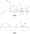
Figure 2A is a longitudinal section view that illustrates a first embodiment of a microwave device for tissue ablation according to the invention; -
Figure 2B is a longitudinal section view of a particular part offigure 2A . -
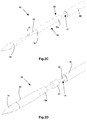
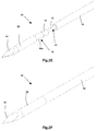
Figures 2C to 2F are perspective views that illustrate the first embodiment of a microwave device for tissue ablation according to the invention; -
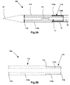
Figure 3A is a longitudinal section view that illustrates a second embodiment of a microwave device for tissue ablation according to the invention; -
Figure 3B is a longitudinal section view of a particular part offigure 3A . -
Figures 3C to 3E are perspective views that illustrate the second embodiment of a microwave device for tissue ablation according to the invention; - In
Figures 1A to 1B amicrowave device 1 for tissue ablation according to the prior art is illustrated that comprises: - a coaxial antenna consisting of a
external conductor 2 in the shape of a hollow cylinder, of ainternal conductor 3 in the shape of a wire, arranged coaxially inside theexternal conductor 2 and of a dielectric insulating material, which is not visible in figures, interposed between theexternal conductor 2 and theinternal conductor 3; - a radiant part, consisting of a prolongation of the
internal conductor 3 to which ametal tip 4, for example of conical shape, is fixed, to give thedevice 1 the ability to penetrate tissues; - a
first sleeve 5 made of dielectric material, preferably a ceramic material, inserted onto the distal end of theexternal conductor 2 and fixed, at a distal end thereof, to thetip 4; thefirst sleeve 5 has adistal part 5a of a greater diameter and aproximal part 5b of a smaller diameter; - a quarter wave impedance transformer, a so-called choke", consisting of a
second sleeve 6 made of electrically conductive material, inserted coaxially on theproximal part 5b of thefirst sleeve 5 made of dielectric material, theproximal end 7 of the choke being closed in a short circuit on theexternal conductor 2 of the coaxial antenna; - a
protection cannula 8, that winds both the coaxial antenna and the choke to give mechanical toughness to thedevice 1. - A
microwave device 1 for tissue ablation like the one illustrated infigures 1A and 1B has two drawbacks. The first is that it is extremely difficult to make joints with great mechanical resistance between the components of the device. In particular, the joints between thefirst sleeve 5 made of ceramic material and themetal tip 4, between thesecond sleeve 6 made of electrically conductive material, constituting the choke, and thedistal part 5a of thefirst sleeve 5 and between the cannula and the firstdistal part 5a of thefirst sleeve 5 are critical. In fact, it is not possible to make said joints by welding because of the presence of thefirst sleeve 5 made of ceramic material and it is therefore necessary to resort to joints by gluing that have much lower mechanical resistance than joints made by welding. - The second drawback of applicators for thermoablation designed according to the model of
Figure 1A and 1B , is that making the choke entails a relatively wide cross section thereof. - Both the aforesaid drawbacks are overcome in a microwave device for tissue ablation according to the invention.
- A first embodiment of a
microwave device 10 for tissue ablation is shown inFigures 2A to 2F . - The
device 10 according to the invention comprises acoaxial antenna 11 consisting of anexternal conductor 12 and of aninternal conductor 13, coaxial to theexternal conductor 12, a dielectric material that is not shown in the Figure being interposed between theinternal conductor 13 andexternal conductor 12. - The
internal conductor 13 is connected, at the distal end thereof, to atip 14, for example of conical shape, that is suitable for facilitating the penetration of thedevice 10 into the tissues of the body of a patient. - On the
external conductor 12 of the coaxial antenna 11 asleeve 15 is inserted that is made of a dielectric material, preferably a ceramic material that is resistant to high temperatures. - At the proximal end of the sleeve 15 a quarter
wave impedance transformer 16 is made, so-called choke, metallising the external surface of said proximal end by depositing thereupon athin layer 16a of metal material, i.e. of an electrically conductive material. - The metal material can be deposited by physical or chemical deposition of vapours of said metal material.
- Metallisation of the external surface of said proximal end extends over a length that is equal to a quarter of wavelength of the electromagnetic field at the operating frequency of the
device 10 or of odd multiples of said quarter of wavelength, such as to ensure appropriate confinement of the retrograde surface currents and consequently greater sphericity of the radiation figure of theantenna 11. As chokes of nearly but not exactly the same length as the choke quoted above also enable an almost spherical radiation Figure to be obtained it is intended that the proposed invention includes the creation, by metallisation of saidsleeve 15, of impedance transformers, or chokes, of nearly but not exactly the same length as a quarter of wavelength of the electromagnetic field at the operating frequency of thedevice 10 or of odd multiples of said quarter of wavelength. The short circuit of the choke can be made by ametal cylinder 17, inserted onto theexternal conductor 12 of the coaxial antenna, in contact with said proximal end of thesleeve 15, and connected electrically with theexternal conductor 12 of thecoaxial antenna 11 and with saidlayer 16a of metal material. - In order to minimise the overall transverse dimension of the
choke 16, it is possible to make themetallisation layer 16a with a thickness that is equal to the minimum required to ensure an almost ideal reflection of the microwaves. It is known that at the interface with a dielectric and a metal the microwaves penetrate inside the metal for a few micrometres, undergoing an exponential attenuation. This pattern is characterised by a length, known as "penetration length", defined as the distance between the dielectric/metal interface and the point inside the metal in which the intensity of the electric field is reduced by a factor equal to the number e (Nepero number) with respect to the intensity of the electric field at said interface. In order to obtain the choke effect, it is sufficient for the thickness of thelayer 16a of metal to be equal to a few penetration lengths, for example three. The thickness of the choke will thus be a few microns, with respect to a thickness of a few tenths of a millimetre of the chokes of the devices known from the prior art. - This result is obtainable only through the technique of depositing metal on the surface of the ceramics disclosed above and enables a choke to be constructed the overall transverse dimension of which is the least possible: this particular implementation of a choke known as a micro-choke is defined below.
- Also the distal end of the
sleeve 15 is covered with a layer ofmetal 18, such layer of metal being deposited with the same technique used to make the micro-choke 16. The layer ofmetal 18 is used to connect thesleeve 15 to thetip 14 by welding, so as to make a connection with great mechanical resistance. - The
device 10 is completed by ametal cannula 19 inserted above saidsleeve 15, and possible by asecond cannula 20 made of non-stick plastics interposed between thecannula 19 and thetip 14 of thedevice 10. - If the short circuit of the choke is made by the
metal cylinder 17, it is advantageous for the latter to be provided with hydraulic seal systems between themetal cylinder 17 and thecannula 19. In fact, the circulation inside thedevice 10 of a coolant is required for removing the heat produced both by the dissipation of power along thecoaxial antenna 11, and by the interaction of the microwaves with the organic tissues. The hydraulic seal between themetal cylinder 17 and thecannula 19 is used to prevent the coolant being able to escape from thedevice 10 and spill into the surrounding tissues. - The
metal cannula 19 can be advantageously fixed to thelayer 16a of metal material by gluing, brazing or mechanical interference, for example crimping, saidlayer 16a of metal material making a hydraulic seal with thecannula 19. - In
figures 3A to 3E a second embodiment of amicrowave device 100 according to the invention is illustrated. The details of this second embodiment are the same as those disclosed infigures 2A to 2F with reference to thefirst embodiment 10 of the microwave device according to the invention are indicated by the same reference numbers. - Similarly to the
device 10 disclosed above, thedevice 100 comprisescoaxial antenna 11 consisting of anexternal conductor 12 and of aninternal conductor 13, coaxial to theexternal conductor 12, a dielectric material being interposed between theinternal conductor 13 and theexternal conductor 12. - The
internal conductor 13 is connected, at the distal end thereof, to atip 14, for example of conical shape, that is suitable for facilitating the penetration of thedevice 100 into the tissues of the body of a patient. - On the
external conductor 12 of the coaxial antenna 11 asleeve 115 is inserted that is made of dielectric material, preferably a ceramic material that is resistant to high temperatures. - The
sleeve 115 consists of a firstdistal part 115a and of a secondproximal part 115b having different diameters, thefirst part 115a having a greater diameter than thesecond part 115b. - The
second part 115b and a portion of thefirst part 115a adjacent to thesecond part 115b are covered by alayer 116a of metal material obtained from physical or chemical deposition of vapours of said metal material. The layer ofmetal material 116 constitutes the quarter wave impedance transformer, or choke, disclosed previously, made with the same criteria disclosed previously. - The layer of
metal material 116a also extends on the linkingsurface 117 between thefirst part 115a and thesecond part 115b of thesleeve 115. - Further, the layer of
metal material 116a also extends over thefront surface 118 of the proximal end of thesleeve 115, until it comes into contact with theexternal conductor 12 of thecoaxial antenna 11, to make the short circuit of the choke. The short circuit can be made by electrically connecting the layer ofmetal material 116a to theexternal conductor 12 by welding. - At the distal end of the
sleeve 115, intended to be connected to thetip 14, asecond layer 119 of metal material is made that is made in a similar manner to thelayer 116a. Thesecond layer 119 is used to permit a connection between welding between thesleeve 115 and themetal tip 14, in such a manner as to obtain a connection with great mechanical resistance. - The
device 100 is completed by acannula 19 in metal material that is inserted above thesecond part 115b of thesleeve 115 until it comes to abut on themetallised linking surface 117 and is fixed by welding, gluing or mechanical interference, for example crimping, to thelayer 116a of metal material to obtain a connection that guarantees a hydraulic seal between thecannula 19 and thesleeve 115 to prevent cooling liquid being able to infiltrate between thecannula 20 and thesleeve 115. - In the practical embodiment the materials, dimensions and constructional details can be different from those indicated but be technically equivalent thereto without thereby falling outside the scope of the present invention.
Claims (18)
- Microwave device (10; 100) for the ablation of biological tissues comprising a coaxial antenna (11), said coaxial antenna (11) comprising an internal conductor (13) surrounded by a layer of dielectric material, an external conductor (12) that is externally coaxial to said layer of dielectric material, a metal tip (14) that is connected electrically to said internal conductor (13), a quarter wave impedance transformer (16; 116) ending in a short circuit, said impedance transformer (16; 116) comprising a sleeve (15; 115) made of dielectric material having a proximal end covered with a layer of metal material (16a; 116a) obtained by depositing said metal material on the surface of said dielectric material, said layer of metal material (16a; 116a) extending for a length near a quarter of wavelength of the electromagnetic field in said dielectric material at the operating frequency of the device (10; 100) or of odd multiples of said quarter of wavelength, said layer of metal material being connected electrically to said external conductor (12), characterised by a metal cannula (19) inserted above said sleeve (15; 1115) and connected to said layer of metal material (16a; 116a) by gluing, brazing, welding or mechanical interference.
- Microwave device (10; 100) according to claim 1, wherein said dielectric material is a ceramic material.
- Microwave device (10; 100) according to claim 1 or 2, wherein said layer of metal material (16a; 116a) is made by physical or chemical deposition of vapours of said metal material on the surface of said sleeve (15; 115).
- Microwave device (10; 100) according to any one of claims 1 to 3, wherein said layer of metal material (16a; 116a) extends over a length that is equal to a value near a quarter of wavelength of the electromagnetic field inside said dielectric material at the operating frequency of the device (10; 100) or to odd multiples of said quarter of wavelength, such as to ensure appropriate confinement of the retrograde surface currents and consequently better sphericity of the radiation pattern.
- Microwave device (10; 100) according to any preceding claim, wherein said layer of metal material (16a; 116a) has a thickness that is at least three times the penetration length of said microwaves in said metal material, at the interface between said metal material and said dielectric material.
- Microwave device (10) according to any preceding claim, further comprising a metal cylinder (17) inserted onto the external conductor (12) of the coaxial antenna (11), in contact with said proximal end of the sleeve (15) made of dielectric material, said metal cylinder (17) being connected electrically to said external conductor (12) and to said layer (16a) of metal material.
- Microwave device (10) according to claim 6, wherein said device is provided with hydraulic seal means.
- Microwave device (10) according to any one of claims 1 to 5, wherein said layer (16a) of metal material also extends on a front surface (15a) of the proximal end of said sleeve (15) and is connected electrically to said external conductor (12).
- Microwave device (10), according to any preceding claim, wherein said layer of metal material (16a) on the surface of said dielectric material is used to ensure the hydraulic seal with the metal cannula (19) by welding, brazing, mechanical interference or gluing.
- Microwave device (10), according to claim 9, further comprising a second cannula (20) made of non-stick plastics, said second cannula (20) being able to be interposed between said metal cannula (19) and said tip (14).
- Microwave device (10), according to any preceding claim, wherein the distal end of said sleeve (15) is covered with a further layer (18) of metal material obtained by depositing said metal material on the surface of said dielectric material.
- Microwave device (10) according to claim 11, wherein said further layer (18) of metal material is connected by brazing, welding, mechanical interference or gluing to said tip (14).
- Microwave device (100), according to any one of claims 1 to 5, wherein said sleeve (115) made of dielectric material comprises a first distal part (115a) and a second proximal part (115b) that have a different diameter, said first part (115a) having a greater diameter than said second part (115b), said layer of metal material (116a) extending over said second part (115b) and over a portion of said first part (115a) adjacent to said second part (115b).
- Microwave device (100), according to claim 13, wherein said layer of metal material (116a) also extends over a linking surface (117) between the first part (115a) and the second part (115b) of the sleeve (115).
- Microwave device (100), according to claim 13, or 14, wherein said layer of metal material (116a) also extends over a front surface (118) of the proximal end of the sleeve (115) and is connected electrically to said external conductor (12).
- Microwave device (100) according to any one of claims 13 to 15, wherein a distal end of the sleeve (115) is configured to be connected to the tip (14), and wherein a second thin layer (119) is made by depositing metal material at said distal end of the sleeve (115).
- Microwave device (100), according to claim 16, wherein said second layer (119) of metal material is connected to said tip (14) by brazing, welding, mechanical interference or gluing.
- Microwave device (100), according to claim 14, wherein said cannula (19) made of metal material is inserted above the second part (115b) of the sleeve (115) until it abuts on the linking surface (117).
Applications Claiming Priority (2)
| Application Number | Priority Date | Filing Date | Title |
|---|---|---|---|
| IT000041A ITMO20120041A1 (en) | 2012-02-17 | 2012-02-17 | MICROWAVE DEVICE FOR FABRIC EXTRACTION |
| PCT/IB2013/051312 WO2013121403A1 (en) | 2012-02-17 | 2013-02-18 | Microwave device for tissue ablation |
Publications (2)
| Publication Number | Publication Date |
|---|---|
| EP2819605A1 EP2819605A1 (en) | 2015-01-07 |
| EP2819605B1 true EP2819605B1 (en) | 2016-04-27 |
Family
ID=46000062
Family Applications (1)
| Application Number | Title | Priority Date | Filing Date |
|---|---|---|---|
| EP13716397.8A Active EP2819605B1 (en) | 2012-02-17 | 2013-02-18 | Microwave device for tissue ablation |
Country Status (8)
| Country | Link |
|---|---|
| US (1) | US10098696B2 (en) |
| EP (1) | EP2819605B1 (en) |
| JP (1) | JP6169621B2 (en) |
| KR (1) | KR20140133581A (en) |
| CN (1) | CN104185454B (en) |
| ES (1) | ES2581536T3 (en) |
| IT (1) | ITMO20120041A1 (en) |
| WO (1) | WO2013121403A1 (en) |
Families Citing this family (16)
| Publication number | Priority date | Publication date | Assignee | Title |
|---|---|---|---|---|
| AU2010247874B2 (en) | 2009-05-11 | 2015-05-14 | TriAgenics, Inc. | Therapeutic tooth bud ablation |
| US10335248B2 (en) | 2009-05-11 | 2019-07-02 | TriAgenics, Inc. | Therapeutic tooth bud ablation |
| WO2014143014A1 (en) | 2013-03-15 | 2014-09-18 | Triagenics, Llc | Therapeutic tooth bud ablation |
| US10624697B2 (en) * | 2014-08-26 | 2020-04-21 | Covidien Lp | Microwave ablation system |
| CN105726121B (en) * | 2016-02-02 | 2020-07-14 | 四川大学华西医院 | A sleeve-loaded multi-slot electromagnetic hemostatic needle |
| CN105596079B (en) * | 2016-02-18 | 2018-09-28 | 赛诺微医疗科技(浙江)有限公司 | For the antenna module of microwave ablation and using its microwave melt needle |
| CN105769338A (en) * | 2016-04-11 | 2016-07-20 | 上海大学 | Microwave ablation probe for interventional therapy of liver cancer |
| CN105816240B (en) * | 2016-05-24 | 2018-09-28 | 赛诺微医疗科技(浙江)有限公司 | For the antenna module of microwave ablation and using its microwave melt needle |
| GB2559604A (en) | 2017-02-13 | 2018-08-15 | Creo Medical Ltd | Microwave energy transfer component for electrosurgical apparatus |
| EP3381393A1 (en) * | 2017-03-31 | 2018-10-03 | National University of Ireland Galway | An ablation probe |
| EP3773293A1 (en) | 2018-03-29 | 2021-02-17 | National University of Ireland Galway | An ablation probe |
| US11730537B2 (en) | 2018-11-13 | 2023-08-22 | Intuitive Surgical Operations, Inc. | Cooled chokes for ablation systems and methods of use |
| CN109953824B (en) * | 2019-04-25 | 2023-05-05 | 南京康友医疗科技有限公司 | A microwave ablation needle body, microwave ablation needle and microwave ablation method |
| EP3979938B1 (en) * | 2019-06-06 | 2024-07-24 | TriAgenics, Inc. | Ablation probe systems |
| WO2021026471A2 (en) | 2019-08-07 | 2021-02-11 | Biocompatibles Uk Limited | Microwave ablation probe |
| MX2023004824A (en) | 2020-10-26 | 2024-03-27 | Triagenics Inc | Ablation probe systems. |
Family Cites Families (12)
| Publication number | Priority date | Publication date | Assignee | Title |
|---|---|---|---|---|
| US4700716A (en) * | 1986-02-27 | 1987-10-20 | Kasevich Associates, Inc. | Collinear antenna array applicator |
| US5150717A (en) * | 1988-11-10 | 1992-09-29 | Arye Rosen | Microwave aided balloon angioplasty with guide filament |
| ITPI20010006A1 (en) * | 2001-01-31 | 2002-07-31 | Cnr Consiglio Naz Delle Ricer | INTERSTITIAL ANTENNA WITH MINIATURIZED CHOKE FOR MICROWAVE HYPERTEMIA APPLICATIONS IN MEDICINE AND SURGERY |
| US6878147B2 (en) * | 2001-11-02 | 2005-04-12 | Vivant Medical, Inc. | High-strength microwave antenna assemblies |
| US7128739B2 (en) * | 2001-11-02 | 2006-10-31 | Vivant Medical, Inc. | High-strength microwave antenna assemblies and methods of use |
| US6706040B2 (en) * | 2001-11-23 | 2004-03-16 | Medlennium Technologies, Inc. | Invasive therapeutic probe |
| ITMO20050034A1 (en) * | 2005-02-11 | 2006-08-12 | Hs Hospital Service Spa | MICROWAVE DEVICE FOR FABRIC APPLICATION. |
| US8463396B2 (en) * | 2009-05-06 | 2013-06-11 | Covidien LLP | Power-stage antenna integrated system with high-strength shaft |
| US8292881B2 (en) | 2009-05-27 | 2012-10-23 | Vivant Medical, Inc. | Narrow gauge high strength choked wet tip microwave ablation antenna |
| US8409187B2 (en) | 2009-09-08 | 2013-04-02 | Covidien Lp | Microwave antenna probe with high-strength ceramic coupler |
| US8394092B2 (en) | 2009-11-17 | 2013-03-12 | Vivant Medical, Inc. | Electromagnetic energy delivery devices including an energy applicator array and electrosurgical systems including same |
| US9561076B2 (en) * | 2010-05-11 | 2017-02-07 | Covidien Lp | Electrosurgical devices with balun structure for air exposure of antenna radiating section and method of directing energy to tissue using same |
-
2012
- 2012-02-17 IT IT000041A patent/ITMO20120041A1/en unknown
-
2013
- 2013-02-18 KR KR20147025870A patent/KR20140133581A/en not_active Ceased
- 2013-02-18 CN CN201380008054.6A patent/CN104185454B/en active Active
- 2013-02-18 WO PCT/IB2013/051312 patent/WO2013121403A1/en not_active Ceased
- 2013-02-18 EP EP13716397.8A patent/EP2819605B1/en active Active
- 2013-02-18 JP JP2014557162A patent/JP6169621B2/en active Active
- 2013-02-18 US US14/379,390 patent/US10098696B2/en active Active
- 2013-02-18 ES ES13716397.8T patent/ES2581536T3/en active Active
Also Published As
| Publication number | Publication date |
|---|---|
| KR20140133581A (en) | 2014-11-19 |
| JP6169621B2 (en) | 2017-07-26 |
| ITMO20120041A1 (en) | 2013-08-18 |
| US20150038956A1 (en) | 2015-02-05 |
| ES2581536T3 (en) | 2016-09-06 |
| JP2015509390A (en) | 2015-03-30 |
| CN104185454A (en) | 2014-12-03 |
| EP2819605A1 (en) | 2015-01-07 |
| WO2013121403A1 (en) | 2013-08-22 |
| HK1200072A1 (en) | 2015-07-31 |
| CN104185454B (en) | 2017-07-21 |
| US10098696B2 (en) | 2018-10-16 |
Similar Documents
| Publication | Publication Date | Title |
|---|---|---|
| US10098696B2 (en) | Microwave device for tissue ablation | |
| US10363096B2 (en) | Method for constructing a dipole antenna | |
| US8409187B2 (en) | Microwave antenna probe with high-strength ceramic coupler | |
| US6527768B2 (en) | End-firing microwave ablation instrument with horn reflection device | |
| EP2926758B1 (en) | Microwave ablation instrument with interchangeable antenna probe | |
| EP2281523B1 (en) | Directive window ablation antenna with dielectric loading | |
| DE69925621T2 (en) | DIRECTIONAL, REFLECTIVE SHIELDING FOR A MICROWAVE DISCOVERING DEVICE | |
| EP2128929B1 (en) | Slidable choke microwave antenna | |
| EP2281522B1 (en) | Electrosurgical devices having dielectric loaded coaxial aperture with distally positioned resonant structure and method of manufacturing the same | |
| EP2008604A2 (en) | Broadband microwave applicator | |
| JP6644863B2 (en) | Microwave device for tissue resection | |
| US10993767B2 (en) | Microwave ablation antenna assemblies | |
| HK1200072B (en) | Microwave device for tissue ablation | |
| AU2014201120A1 (en) | Slidable choke microwave antenna |
Legal Events
| Date | Code | Title | Description |
|---|---|---|---|
| PUAI | Public reference made under article 153(3) epc to a published international application that has entered the european phase |
Free format text: ORIGINAL CODE: 0009012 |
|
| 17P | Request for examination filed |
Effective date: 20140917 |
|
| AK | Designated contracting states |
Kind code of ref document: A1 Designated state(s): AL AT BE BG CH CY CZ DE DK EE ES FI FR GB GR HR HU IE IS IT LI LT LU LV MC MK MT NL NO PL PT RO RS SE SI SK SM TR |
|
| AX | Request for extension of the european patent |
Extension state: BA ME |
|
| DAX | Request for extension of the european patent (deleted) | ||
| REG | Reference to a national code |
Ref country code: HK Ref legal event code: DE Ref document number: 1200072 Country of ref document: HK |
|
| GRAP | Despatch of communication of intention to grant a patent |
Free format text: ORIGINAL CODE: EPIDOSNIGR1 |
|
| INTG | Intention to grant announced |
Effective date: 20151105 |
|
| RIN1 | Information on inventor provided before grant (corrected) |
Inventor name: TOSORATTI, NEVIO Inventor name: AMABILE, CLAUDIO Inventor name: CASSARINO, SIMONE |
|
| GRAS | Grant fee paid |
Free format text: ORIGINAL CODE: EPIDOSNIGR3 |
|
| GRAA | (expected) grant |
Free format text: ORIGINAL CODE: 0009210 |
|
| AK | Designated contracting states |
Kind code of ref document: B1 Designated state(s): AL AT BE BG CH CY CZ DE DK EE ES FI FR GB GR HR HU IE IS IT LI LT LU LV MC MK MT NL NO PL PT RO RS SE SI SK SM TR |
|
| REG | Reference to a national code |
Ref country code: GB Ref legal event code: FG4D |
|
| REG | Reference to a national code |
Ref country code: CH Ref legal event code: EP |
|
| REG | Reference to a national code |
Ref country code: AT Ref legal event code: REF Ref document number: 793877 Country of ref document: AT Kind code of ref document: T Effective date: 20160515 |
|
| REG | Reference to a national code |
Ref country code: IE Ref legal event code: FG4D |
|
| REG | Reference to a national code |
Ref country code: DE Ref legal event code: R096 Ref document number: 602013007049 Country of ref document: DE |
|
| REG | Reference to a national code |
Ref country code: LT Ref legal event code: MG4D |
|
| REG | Reference to a national code |
Ref country code: NL Ref legal event code: MP Effective date: 20160427 |
|
| REG | Reference to a national code |
Ref country code: ES Ref legal event code: FG2A Ref document number: 2581536 Country of ref document: ES Kind code of ref document: T3 Effective date: 20160906 |
|
| REG | Reference to a national code |
Ref country code: AT Ref legal event code: MK05 Ref document number: 793877 Country of ref document: AT Kind code of ref document: T Effective date: 20160427 |
|
| PG25 | Lapsed in a contracting state [announced via postgrant information from national office to epo] |
Ref country code: NL Free format text: LAPSE BECAUSE OF FAILURE TO SUBMIT A TRANSLATION OF THE DESCRIPTION OR TO PAY THE FEE WITHIN THE PRESCRIBED TIME-LIMIT Effective date: 20160427 |
|
| PG25 | Lapsed in a contracting state [announced via postgrant information from national office to epo] |
Ref country code: FI Free format text: LAPSE BECAUSE OF FAILURE TO SUBMIT A TRANSLATION OF THE DESCRIPTION OR TO PAY THE FEE WITHIN THE PRESCRIBED TIME-LIMIT Effective date: 20160427 Ref country code: PL Free format text: LAPSE BECAUSE OF FAILURE TO SUBMIT A TRANSLATION OF THE DESCRIPTION OR TO PAY THE FEE WITHIN THE PRESCRIBED TIME-LIMIT Effective date: 20160427 Ref country code: NO Free format text: LAPSE BECAUSE OF FAILURE TO SUBMIT A TRANSLATION OF THE DESCRIPTION OR TO PAY THE FEE WITHIN THE PRESCRIBED TIME-LIMIT Effective date: 20160727 Ref country code: LT Free format text: LAPSE BECAUSE OF FAILURE TO SUBMIT A TRANSLATION OF THE DESCRIPTION OR TO PAY THE FEE WITHIN THE PRESCRIBED TIME-LIMIT Effective date: 20160427 |
|
| REG | Reference to a national code |
Ref country code: HK Ref legal event code: GR Ref document number: 1200072 Country of ref document: HK |
|
| PG25 | Lapsed in a contracting state [announced via postgrant information from national office to epo] |
Ref country code: HR Free format text: LAPSE BECAUSE OF FAILURE TO SUBMIT A TRANSLATION OF THE DESCRIPTION OR TO PAY THE FEE WITHIN THE PRESCRIBED TIME-LIMIT Effective date: 20160427 Ref country code: LV Free format text: LAPSE BECAUSE OF FAILURE TO SUBMIT A TRANSLATION OF THE DESCRIPTION OR TO PAY THE FEE WITHIN THE PRESCRIBED TIME-LIMIT Effective date: 20160427 Ref country code: GR Free format text: LAPSE BECAUSE OF FAILURE TO SUBMIT A TRANSLATION OF THE DESCRIPTION OR TO PAY THE FEE WITHIN THE PRESCRIBED TIME-LIMIT Effective date: 20160728 Ref country code: SE Free format text: LAPSE BECAUSE OF FAILURE TO SUBMIT A TRANSLATION OF THE DESCRIPTION OR TO PAY THE FEE WITHIN THE PRESCRIBED TIME-LIMIT Effective date: 20160427 Ref country code: AT Free format text: LAPSE BECAUSE OF FAILURE TO SUBMIT A TRANSLATION OF THE DESCRIPTION OR TO PAY THE FEE WITHIN THE PRESCRIBED TIME-LIMIT Effective date: 20160427 Ref country code: RS Free format text: LAPSE BECAUSE OF FAILURE TO SUBMIT A TRANSLATION OF THE DESCRIPTION OR TO PAY THE FEE WITHIN THE PRESCRIBED TIME-LIMIT Effective date: 20160427 Ref country code: PT Free format text: LAPSE BECAUSE OF FAILURE TO SUBMIT A TRANSLATION OF THE DESCRIPTION OR TO PAY THE FEE WITHIN THE PRESCRIBED TIME-LIMIT Effective date: 20160829 |
|
| PG25 | Lapsed in a contracting state [announced via postgrant information from national office to epo] |
Ref country code: BE Free format text: LAPSE BECAUSE OF FAILURE TO SUBMIT A TRANSLATION OF THE DESCRIPTION OR TO PAY THE FEE WITHIN THE PRESCRIBED TIME-LIMIT Effective date: 20160427 |
|
| REG | Reference to a national code |
Ref country code: FR Ref legal event code: PLFP Year of fee payment: 5 |
|
| REG | Reference to a national code |
Ref country code: DE Ref legal event code: R097 Ref document number: 602013007049 Country of ref document: DE |
|
| PG25 | Lapsed in a contracting state [announced via postgrant information from national office to epo] |
Ref country code: DK Free format text: LAPSE BECAUSE OF FAILURE TO SUBMIT A TRANSLATION OF THE DESCRIPTION OR TO PAY THE FEE WITHIN THE PRESCRIBED TIME-LIMIT Effective date: 20160427 Ref country code: SK Free format text: LAPSE BECAUSE OF FAILURE TO SUBMIT A TRANSLATION OF THE DESCRIPTION OR TO PAY THE FEE WITHIN THE PRESCRIBED TIME-LIMIT Effective date: 20160427 Ref country code: CZ Free format text: LAPSE BECAUSE OF FAILURE TO SUBMIT A TRANSLATION OF THE DESCRIPTION OR TO PAY THE FEE WITHIN THE PRESCRIBED TIME-LIMIT Effective date: 20160427 Ref country code: EE Free format text: LAPSE BECAUSE OF FAILURE TO SUBMIT A TRANSLATION OF THE DESCRIPTION OR TO PAY THE FEE WITHIN THE PRESCRIBED TIME-LIMIT Effective date: 20160427 Ref country code: RO Free format text: LAPSE BECAUSE OF FAILURE TO SUBMIT A TRANSLATION OF THE DESCRIPTION OR TO PAY THE FEE WITHIN THE PRESCRIBED TIME-LIMIT Effective date: 20160427 |
|
| PG25 | Lapsed in a contracting state [announced via postgrant information from national office to epo] |
Ref country code: SM Free format text: LAPSE BECAUSE OF FAILURE TO SUBMIT A TRANSLATION OF THE DESCRIPTION OR TO PAY THE FEE WITHIN THE PRESCRIBED TIME-LIMIT Effective date: 20160427 |
|
| PLBE | No opposition filed within time limit |
Free format text: ORIGINAL CODE: 0009261 |
|
| STAA | Information on the status of an ep patent application or granted ep patent |
Free format text: STATUS: NO OPPOSITION FILED WITHIN TIME LIMIT |
|
| 26N | No opposition filed |
Effective date: 20170130 |
|
| PG25 | Lapsed in a contracting state [announced via postgrant information from national office to epo] |
Ref country code: SI Free format text: LAPSE BECAUSE OF FAILURE TO SUBMIT A TRANSLATION OF THE DESCRIPTION OR TO PAY THE FEE WITHIN THE PRESCRIBED TIME-LIMIT Effective date: 20160427 |
|
| PG25 | Lapsed in a contracting state [announced via postgrant information from national office to epo] |
Ref country code: MC Free format text: LAPSE BECAUSE OF FAILURE TO SUBMIT A TRANSLATION OF THE DESCRIPTION OR TO PAY THE FEE WITHIN THE PRESCRIBED TIME-LIMIT Effective date: 20160427 |
|
| REG | Reference to a national code |
Ref country code: CH Ref legal event code: PL |
|
| PG25 | Lapsed in a contracting state [announced via postgrant information from national office to epo] |
Ref country code: LI Free format text: LAPSE BECAUSE OF NON-PAYMENT OF DUE FEES Effective date: 20170228 Ref country code: CH Free format text: LAPSE BECAUSE OF NON-PAYMENT OF DUE FEES Effective date: 20170228 |
|
| REG | Reference to a national code |
Ref country code: IE Ref legal event code: MM4A |
|
| PG25 | Lapsed in a contracting state [announced via postgrant information from national office to epo] |
Ref country code: LU Free format text: LAPSE BECAUSE OF NON-PAYMENT OF DUE FEES Effective date: 20170218 |
|
| REG | Reference to a national code |
Ref country code: FR Ref legal event code: PLFP Year of fee payment: 6 |
|
| PG25 | Lapsed in a contracting state [announced via postgrant information from national office to epo] |
Ref country code: IE Free format text: LAPSE BECAUSE OF NON-PAYMENT OF DUE FEES Effective date: 20170218 |
|
| PG25 | Lapsed in a contracting state [announced via postgrant information from national office to epo] |
Ref country code: MT Free format text: LAPSE BECAUSE OF NON-PAYMENT OF DUE FEES Effective date: 20170218 |
|
| PG25 | Lapsed in a contracting state [announced via postgrant information from national office to epo] |
Ref country code: AL Free format text: LAPSE BECAUSE OF FAILURE TO SUBMIT A TRANSLATION OF THE DESCRIPTION OR TO PAY THE FEE WITHIN THE PRESCRIBED TIME-LIMIT Effective date: 20160427 |
|
| PG25 | Lapsed in a contracting state [announced via postgrant information from national office to epo] |
Ref country code: HU Free format text: LAPSE BECAUSE OF FAILURE TO SUBMIT A TRANSLATION OF THE DESCRIPTION OR TO PAY THE FEE WITHIN THE PRESCRIBED TIME-LIMIT; INVALID AB INITIO Effective date: 20130218 |
|
| PG25 | Lapsed in a contracting state [announced via postgrant information from national office to epo] |
Ref country code: BG Free format text: LAPSE BECAUSE OF FAILURE TO SUBMIT A TRANSLATION OF THE DESCRIPTION OR TO PAY THE FEE WITHIN THE PRESCRIBED TIME-LIMIT Effective date: 20160427 |
|
| PG25 | Lapsed in a contracting state [announced via postgrant information from national office to epo] |
Ref country code: CY Free format text: LAPSE BECAUSE OF FAILURE TO SUBMIT A TRANSLATION OF THE DESCRIPTION OR TO PAY THE FEE WITHIN THE PRESCRIBED TIME-LIMIT Effective date: 20160427 |
|
| PG25 | Lapsed in a contracting state [announced via postgrant information from national office to epo] |
Ref country code: MK Free format text: LAPSE BECAUSE OF FAILURE TO SUBMIT A TRANSLATION OF THE DESCRIPTION OR TO PAY THE FEE WITHIN THE PRESCRIBED TIME-LIMIT Effective date: 20160427 |
|
| PG25 | Lapsed in a contracting state [announced via postgrant information from national office to epo] |
Ref country code: TR Free format text: LAPSE BECAUSE OF FAILURE TO SUBMIT A TRANSLATION OF THE DESCRIPTION OR TO PAY THE FEE WITHIN THE PRESCRIBED TIME-LIMIT Effective date: 20160427 |
|
| PG25 | Lapsed in a contracting state [announced via postgrant information from national office to epo] |
Ref country code: IS Free format text: LAPSE BECAUSE OF FAILURE TO SUBMIT A TRANSLATION OF THE DESCRIPTION OR TO PAY THE FEE WITHIN THE PRESCRIBED TIME-LIMIT Effective date: 20160827 |
|
| PGFP | Annual fee paid to national office [announced via postgrant information from national office to epo] |
Ref country code: GB Payment date: 20260227 Year of fee payment: 14 |
|
| PGFP | Annual fee paid to national office [announced via postgrant information from national office to epo] |
Ref country code: ES Payment date: 20260302 Year of fee payment: 14 |
|
| PGFP | Annual fee paid to national office [announced via postgrant information from national office to epo] |
Ref country code: DE Payment date: 20260227 Year of fee payment: 14 |
|
| PGFP | Annual fee paid to national office [announced via postgrant information from national office to epo] |
Ref country code: IT Payment date: 20260224 Year of fee payment: 14 |
|
| PGFP | Annual fee paid to national office [announced via postgrant information from national office to epo] |
Ref country code: FR Payment date: 20260225 Year of fee payment: 14 |