EP2819323A1 - Detection of alien signal injection in passive optical networks - Google Patents
Detection of alien signal injection in passive optical networks Download PDFInfo
- Publication number
- EP2819323A1 EP2819323A1 EP13305917.0A EP13305917A EP2819323A1 EP 2819323 A1 EP2819323 A1 EP 2819323A1 EP 13305917 A EP13305917 A EP 13305917A EP 2819323 A1 EP2819323 A1 EP 2819323A1
- Authority
- EP
- European Patent Office
- Prior art keywords
- optical
- olt
- branching device
- network
- signal
- Prior art date
- Legal status (The legal status is an assumption and is not a legal conclusion. Google has not performed a legal analysis and makes no representation as to the accuracy of the status listed.)
- Granted
Links
Images



Classifications
-
- H—ELECTRICITY
- H04—ELECTRIC COMMUNICATION TECHNIQUE
- H04B—TRANSMISSION
- H04B10/00—Transmission systems employing electromagnetic waves other than radio-waves, e.g. infrared, visible or ultraviolet light, or employing corpuscular radiation, e.g. quantum communication
- H04B10/27—Arrangements for networking
- H04B10/272—Star-type networks or tree-type networks
-
- H—ELECTRICITY
- H04—ELECTRIC COMMUNICATION TECHNIQUE
- H04B—TRANSMISSION
- H04B10/00—Transmission systems employing electromagnetic waves other than radio-waves, e.g. infrared, visible or ultraviolet light, or employing corpuscular radiation, e.g. quantum communication
- H04B10/07—Arrangements for monitoring or testing transmission systems; Arrangements for fault measurement of transmission systems
- H04B10/075—Arrangements for monitoring or testing transmission systems; Arrangements for fault measurement of transmission systems using an in-service signal
- H04B10/079—Arrangements for monitoring or testing transmission systems; Arrangements for fault measurement of transmission systems using an in-service signal using measurements of the data signal
- H04B10/0793—Network aspects, e.g. central monitoring of transmission parameters
-
- H—ELECTRICITY
- H04—ELECTRIC COMMUNICATION TECHNIQUE
- H04B—TRANSMISSION
- H04B10/00—Transmission systems employing electromagnetic waves other than radio-waves, e.g. infrared, visible or ultraviolet light, or employing corpuscular radiation, e.g. quantum communication
- H04B10/29—Repeaters
-
- H—ELECTRICITY
- H04—ELECTRIC COMMUNICATION TECHNIQUE
- H04B—TRANSMISSION
- H04B10/00—Transmission systems employing electromagnetic waves other than radio-waves, e.g. infrared, visible or ultraviolet light, or employing corpuscular radiation, e.g. quantum communication
- H04B10/80—Optical aspects relating to the use of optical transmission for specific applications, not provided for in groups H04B10/03 - H04B10/70, e.g. optical power feeding or optical transmission through water
- H04B10/85—Protection from unauthorised access, e.g. eavesdrop protection
Definitions
- the present invention relates to the field of telecommunications networks and, more particularly, to optical access networks.
- PON passive optical network
- ITU International Telecommunication Union
- EPON institute of Electrical and Electronics Engineers
- a passive optical distribution network has a branching structure with an optical line terminal (OLT) at its root, and a number of optical network units (ONUs) or optical network terminals (ONTs) at the leaves, notably ONTs assigned to end subscribers.
- ONT optical network units
- ONTs optical network terminals
- ONTs optical network terminals
- ONTs optical network terminals
- the branching structure is obtained by means of 1-to-N splitter/combiner devices, that is branching devices having a single port on the side towards the OLT and N ports on the side towards the subscriber terminals.
- the branching devices used in passive optical networks may be entirely passive.
- active branching devices are sometimes employed to ensure efficient usage of an OLT, notably in situations where an optical access network serves multiple buildings each of which only contains a few subscribers and it is desired to configure the network so that subscribers from the different buildings can be served by a single (or common) line (or service or user) port on the OLT.
- Active branching devices not only perform a splitting/combining function but also include optical-electrical-optical converter switch that convert the optical signals arriving at the device from the optical domain to the electrical domain and back again. This makes it possible to perform various functions, such as re-amplifying the signals, synchronization in TDM-PONs, and so on. Active branching devices of this kind are sometimes called virtual optical couplers (VOCs).
- VOCs virtual optical couplers
- the upstream communications channel i.e. the communications channel in the direction from the ONTs towards the OLT
- the upstream channel is shared by multiple subscribers.
- the upstream channel is shared by the ONTs, if a single malicious or malfunctioning ONT emits a signal in the upstream direction, and that signal has a wavelength that interferes with the wavelength usually used for upstream communications (e.g. 1310nm in GPON), then the quality of communications on this part of the optical distribution network will be degraded, perhaps to the point of disrupting communications completely.
- DoS attack denial of service attack
- upstream signal refers to a signal propagating in the direction from the ONTs towards the OLT and the expression “downstream signal” refers to a signal propagating in the direction from the OLT towards the ONTs.
- the present invention has been made in view of the above-mentioned disadvantages.
- the present invention provides a method of identifying the location of a source of an interfering upstream signal in an optical distribution network comprising an optical line terminal (OLT) connected to a plurality of optical network terminals (ONTs) via a 1-to-N branching device having a first port connected to the OLT and N second ports connected to N respective network branches extending towards the ONTs, the interfering signal propagating in the upstream direction towards the OLT, the method comprising the steps of:
- the method according to the invention allows the source of an interfering upstream signal on a PON to be localized because, according to the standards currently in place for GPON and other passive optical networks, when the downstream transmissions from an OLT stop being received by ONTs those ONTs are supposed to stop sending signals upstream.
- the method proposed by the invention enables malfunctioning or misbehaving ONTs, or other signal sources, to be localized because such devices will not follow this standard behaviour when the OLT downstream transmissions are interrupted; instead they will continue upstream transmissions.
- the method according to the invention can identify this network branch as the location of the source of an interfering upstream signal.
- the 1-to-N branching device may comprise active optical-electrical-optical (OEO) converters that are configured to convert signals received at the branching device from optical form, to electrical form, and back to optical form.
- OEO optical-electrical-optical
- the optical-electrical-optical converters of this kind of branching device can be controlled to implement various steps in different methods embodying the invention.
- suitable control of the OEO converters enables: downstream OLT transmissions to be prevented from reaching the different network branches connected to the branching device, and misbehaving network branches to be disconnected from the OLT.
- branching devices having active couplers/converters of this kind it is possible to make power measurements on the upstream signals received on the individual network branches.
- the present invention further provides a 1-to-N optical branching device comprising :
- An optical branching device configured according to the invention can identify the network branch containing the source of an interfering upstream signal in a PON so that suitable remedial action may be taken.
- control unit of the optical branching device may be configured to control the second optical converters to interrupt downstream OLT transmissions to the respective connected network branches one by one. In this manner, at any given time only a part of the optical network is affected by the process for localizing the source of the interfering upstream signal.
- different action can be taken when the source of the interfering signal has been localized.
- a notification can be generated identifying the branching device's second port where the interfering signal is present and this notification can be used in any convenient manner (e.g. logged at the branching device or elsewhere, emitted as an alarm either locally or remotely, transmitted to the connected OLT, and so on).
- suitable countermeasures can be taken. In certain embodiments of the invention a countermeasure is applied whereby the affected network branch is automatically isolated from the OLT (e.g. the branching device breaks the connection between the offending network branch and the OLT).
- control unit of the above-mentioned optical branching device comprising OEO converters may be configured to control the second optical converter connected to the second port where the interfering signal is present, to prevent upstream signals received at this port from being transmitted to the OLT.
- branching devices including OEO converters are already being included in some passive optical networks, for example to ensure efficient usage of OLT ports.
- Embodiments of the invention adapt such branching devices so that they can be used to identify the location of the source of an interfering upstream signal and, if desired, so that appropriate counter measures may be taken.
- the required adaptation may be implemented by suitable configuring of the control logic that is employed in the branching device.
- upstream transmissions on a network branch that has been cut off from the OLT may still be monitored, notably to determine whether the interfering upstream signal ceases.
- the network branch may be re-connected into the network if it has ceased to carry the interfering signal.
- control unit of the above-mentioned optical branching device comprising OEO converters may be configured to perform such monitoring and to control the second optical converter connected to the second port where the interfering signal is present, to re-connect the network branch to the OLT when the network branch in question has stopped transmitting signals in the upstream direction.
- the performance of the method of localizing the source of an interfering signal is triggered by a determination that there has been degradation in signals propagating in the PON.
- the branching device may be configured to monitor signals on the PON to detect when signal degradation occurs and a finding of signal degradation may then lead to performance of a method according to the invention so as to identify a network branch propagating an interfering upstream signal.
- the branching device may receive a command notification, for example from the connected OLT, notifying it of signal degradation in the network and triggering it to seek the source of an interfering upstream signal by implementing a method according to the invention.
- the present invention still further provides an optical line terminal (OLT) of an optical communications network, the OLT comprising:
- OLTs are already equipped with algorithms enabling signal degradation to be detected and this can be exploited by adapting the OLT (e.g. via its associated management system) to respond to detection of signal degradation by transmitting a triggering command or notification to the branching device to trigger a search for the branch of the network containing the misbehaving device.
- the present invention is not limited to application in any one particular type of passive optical network: to the contrary the invention may be applied in PONs according to various industry standards including but not limited to GPON, EPON, GEPON, BPON and APON.
- Fig.1 illustrates an example of application of the invention in the context of an FTTH (fiber-to-the-home) PON topology.
- FTTH fiber-to-the-home
- the fact that Fig.1 represents a FTTH topology is purely illustrative; the invention can be applied more generally in substantially any FTTx PON topology to detect which branch in a passive optical network's branching structure is the source of an interfering upstream signal.
- the passive optical network 1 illustrated in Fig.1 includes an optical line terminal 2 connected to a number N of optical network terminals 6 via a feeder optical fiber 3, a 1-to-N branching device 4, and N drop fibers 5.
- the branching device 4 has a first port A on the side towards the OLT and N second ports B on the side towards the ONTs. Which of the ports A and B is considered to be the input or output port of the branching device 4 depends on whether transmission from the OLT to the ONTs is considered or whether transmissions from the ONTs towards the OLT are being considered.
- the branching device 4 illustrated in Fig.1 includes first and second active couplers/converters, 41 and 42, having an optical-electrical conversion function and an electrical-optical conversion function.
- a management system 43 of the branching device 4 applies control logic to ensure appropriate control of the active converters 41 and 42, for example to implement functions such as power supply, control of coupling, and so on.
- a typical value of N in a branching device including active converters used nowadays is 2, 4 or sometimes 8.
- the present invention does not impose any specific limit on the value of the number N, other than that N is 2 or more, but it may be limited by other practical constraints.
- a downstream signal from the OLT towards the ONTs received at port A of the branching device 4 undergoes optical-electrical conversion at the first active converter 41, any desired processing in the electrical domain, electrical-to-optical conversion at a second active converter 42 and output at a port B of the branching device, along with the necessary splitting to N parallel channels.
- An upstream signal undergoes the inverse of this processing.
- the branching device 4 is configured to exhibit, at its OLT side, behavior similar to that of an ONT, that is, the branching device 4 is configured to have an OMCI channel (ONT Management and Control channel) established with the OLT, to add its own serial number to communications, and may be provisioned in the OLT management system as an ONU/ONT.
- OMCI channel ONT Management and Control channel
- the OLT transmits signals downstream, that is in the direction towards the ONTs, at a wavelength of 1490 nm, and the ONTs reply with signals in the upstream direction at a wavelength of 1310 nm (as in the GPON standard).
- the present invention is not particularly limited having regard to the specific wavelengths used by the OLT and ONTs, the values represented in Fig.1 correspond to values employed in various PONs in use today.
- a light source X associated with the connection to the illustrated ONT 6 outputs an upstream signal at or in the region of 1310nm and injects the alien (interfering) signal into the network branch 5 X via a splitter sp.
- the upstream signal from source X is received at a port designated B X in Fig.4 and the signal is combined with upstream signals from the other ports B and transferred to port A for onward transmission to the OLT 2.
- the upstream signal from source X tends to cause degradation of the optical transmissions in the upstream direction.
- the present invention may be applied even when the upstream signal causing signal degradation is emitted by source X at a wavelength different from the standard wavelength for upstream transmissions and irrespective of whether source X emits a continuous, intermittent or modulated signal.
- Fig.1 illustrates a PON 1 in which the branching device 4 is adapted by the addition of a detection unit 10 that is configured to detect interfering upstream signals, notably of the kind involved in DoS attacks on the network.
- the detection unit 10 may be implemented in a variety of ways, depending on the application and the designer's objectives.
- the detection unit 10 may be provided as a dedicated software or hardware module, it may be implemented by adjusting the control logic implemented by the management system 43, and so on.
- the detection unit 10 is arranged to receive a signal sig1 indicating that interference in the upstream channel has been detected.
- sig1 is generated by the management system 43 of the branching unit when degradation of the upstream signal at 1310nm is detected at the branching device 4 (management system 43 may be configured to monitor signal quality in an ongoing manner).
- sig1 may be generated in response to detection of signal degradation at the OLT, for example when the OLT generates a "signal degraded" alarm or similar notification. In the latter case the OLT may be configured to send the branching device 4 (or the associated detection unit 10) a direct triggering command directing the branching device 4 to implement a method to localize the source of an interfering upstream signal.
- the OLT may be configured to send the branching device 4 (or detection unit 10) an indirect triggering command in the form of a notification that signal degradation has been detected, and in that case the branching device 4 is configured to respond to the received notification by implementing the source-localization method.
- the triggering command may be sent by a monitoring module associated with the OLT.
- the detection unit 10 is configured to output a signal sig2 in response to receipt of the signal sig 1.
- Signal sig2 controls the second active couplers/converters 42 to switch off the downstream 1490nm signal from the OLT, i.e. to prevent it from reaching the ports B of the branching device.
- Detection unit 10 is also configured to input measurement signals sig3 indicating the optical power received at each of the ports B of the branching device.
- Detection unit 10 is also configured to produce a signal sig4 based on its internal processing.
- Signal sig4 controls a specific one (or, in principle, more than one) second active coupler/converter 42 to prevent a 1310nm signal received from a connected one of the ports B from reaching the port A of the branching device 4.
- a first step, S1, of the Fig.2 method the quality of upstream transmissions in the PON 1 of Fig.1 are monitored. As indicated above, this monitoring may be performed at the branching device 4 or at the OLT 2 or, indeed, in principle at some other location where upstream transmissions in the network 1 can be accessed.
- this monitoring it is verified, in a step S2, whether or not the quality of the upstream signal has degraded to a particular extent. For example, it may be checked whether the bit error rate, frame error rate or the like in an upstream channel has exceeded a threshold that corresponds to a specific absolute or relative degree of signal degradation. If the signal quality is still sufficiently good the flow returns to the monitoring of step S1.
- step S2 if a determined degree of signal degradation has been detected in step S2 then a method is triggered for seeking the network branch that contains the source of an interfering upstream signal (the presumed cause of the signal degradation).
- the detection of signal degradation in step S2 results in production of a triggering signal sig1 that is supplied to the detection unit 10 of Fig.1 .
- the detection unit 10 manages performance of the source-localization method according to the present embodiment of the invention.
- the detection unit 10 emits control signals sig2 to the second optical converters 42 of the branching device 4 one by one, so that the downstream 1460nm signal from the OLT is temporarily cut off from each of the ports B of the branching device.
- a timer (not shown) times a predetermined time period to between the time when the 1490nm downstream signal is interrupted on the selected network branch and a measurement time.
- the duration of the interval t 0 is set very short then well-behaved ONTs may not have time to power down their lasers and cease upstream transmissions before measurement is made, leading to a false finding that a network branch containing the relevant ONT is the source of an interfering signal.
- the time interval t 0 is set long then subscribers using the network may be inconvenienced by the interruption of their connection in step S4 of the method.
- An implementation of the invention using a time interval t 0 of 50 ms duration gives good results, but the invention is not limited to a duration t 0 of this specific value and, in particular, shorter or longer time periods may be set, as convenient.
- the detection unit 10 receives signals indicating the optical power measured at the ports B and, in particular, receives a signal sig3 indicating the optical power measured on the port which is currently cut off from the downstream OLT signals (step S6). After time t 0 has elapsed, the detection unit 10 is configured to compare the power level measured at the relevant port B against a threshold level ⁇ (in step S7 of Fig.2 ).
- a suitable threshold power level is -28dBm. This value corresponds to the minimum sensitivity level that is required for an OLT by the ITU-T GPON standard (i.e. the lower limit on the power level of signals, received at the OLT's optical port, which the OLT must be capable of serving correctly). Adopting a ⁇ value that is substantially the same as the minimum sensitivity level of the OLT seeks to ensure that the branching device 4 behaves similarly to an OLT from the point of view of the users (end ONTs). However, if desired ⁇ may be set to a value different from the minimum sensitivity level of the OLT.
- the detection unit 10 identifies the current port under test, in this case B X , as the port connected to the network branch 5 X containing the source X of the disturbance on the network (S DIST , in step S10 of Fig.2 ).
- the detection unit 10 may be configured to output a signal sig4 to the active optical coupler 42 connected to the identified network branch containing the source of the interfering upstream signal, so that this active coupler decouples the 1310nm signals received at the connected port B from the OLT side of the branching device 4 (step S11 indicated in dashed lines in Fig.2 ).
- the detection unit 10 prevents downstream OLT signals from reaching the different network branches by controlling the optical converters 42 one by one. If desired, the detection unit 10 can control the second active converters 42 to interrupt the downstream OLT signals at all of the ports B simultaneously or, indeed, the detection unit 10 can control the first active converter 41 to interrupt the downstream signals at port A of the branching device, or the downstream signals may be interrupted at the OLT, or at a point between the OLT and the port A.
- Fig.3 is a flow diagram illustrating an approach in which the detection unit 10 controls the second active converters 42 to interrupt the downstream OLT signals at all of the ports B simultaneously.
- Steps S31 and S32 of Fig.3 correspond to steps S1 and S2 of Fig.2 .
- the downstream signals are cut off from the whole set of ports B simultaneously.
- step S34 the timer times the time interval t 0 and then, in step S35, power measurements are taken for all of the ports B.
- step S36 the power measurements are checked to identify which power measurement equals or exceeds the threshold ⁇ .
- step S36 determines that the network branch 5 X connected to the port B X contains a source that is still transmitting upstream with power greater than the threshold level, even in the absence of downstream signals from the OLT 2 and so, in step S37, the network branch 5 X connected to port B X is identified as the location of the source of the disturbance of the network (source of the alien signal injection).
- step S38 the connections on the other ports are restored so that they start to receive downstream signals from the OLT once again. If desired, the upstream signals from the offending network branch 5 X are blocked using the active converter 42 connected to port B X (step S39 in Fig.3 ).
- Fig.4 illustrates certain additional steps that may be implemented in methods according to the present invention to enable, in appropriate cases, the reconnection of network branches that previously have been isolated from the network.
- the additional steps of Fig.4 will be described in the context of one example of implementation using the apparatus of Fig.1 .
- step S41 after action has been taken (step S41) to prevent signals from a specific network branch, here 5 X , from being transmitted to the OLT, the upstream signals coming from this network branch 5 X continue to be monitored to see whether the power has fallen below a second threshold level ⁇ 2 (step S42).
- step S41 in Fig.4 corresponds to step S12 in Fig.2 and to step S39 in Fig.3 ). If the monitoring in step S42 shows that the power level remains too high (greater than ⁇ 2 ) it is inferred that the offending network branch 5 X is still propagating an upstream signal that would degrade signal quality in the optical network, and the monitoring continues.
- step S42 results in a positive outcome the detection unit 10 controls the active coupler 42 serving the port B X connected to the network branch 5 X to allow downstream signals from the OLT to reach this network branch 5 X (step S43) and to allow upstream signals from this network branch 5 X to be propagated towards the OLT (step S44).
- threshold level ⁇ 2 used to decide whether or not the isolated network branch should be re-connected is set the same as the threshold level ⁇ used (e.g. in step S7 of Fig.2 ) to locate the network branch containing a misbehaving device, for example to -28 dBm.
- threshold level ⁇ 2 may be set to a different value from ⁇ , notably it may be set to a lower value so as to ensure that re-connection truly is justified.
- the branching device 4 (more particularly, the detection unit 10) may be configured to send various notifications, to the OLT 2 or another desired device, for example a notification indicating that a specified network branch has been re-connected following performance of the additional steps represented in Fig.4 .
Landscapes
- Engineering & Computer Science (AREA)
- Physics & Mathematics (AREA)
- Electromagnetism (AREA)
- Computer Networks & Wireless Communication (AREA)
- Signal Processing (AREA)
- Computing Systems (AREA)
- Computer Security & Cryptography (AREA)
- Optical Communication System (AREA)
- Small-Scale Networks (AREA)
Abstract
Description
- The present invention relates to the field of telecommunications networks and, more particularly, to optical access networks.
- One of the most common architectures that is employed for optical access networks is a passive optical network (PON). Various standards have been defined for PONs including, but not limited to, GPON (standardized by the International Telecommunication Union, ITU) and EPON (standardized by the institute of Electrical and Electronics Engineers, IEEE).
- Typically, a passive optical distribution network (ODN) has a branching structure with an optical line terminal (OLT) at its root, and a number of optical network units (ONUs) or optical network terminals (ONTs) at the leaves, notably ONTs assigned to end subscribers. It is to be understood that in the rest of the present document the expression ONT (and the plural form ONTs) will be used to cover also optical network units (ONUs), unless the context demands otherwise. In a PON the branching structure is obtained by means of 1-to-N splitter/combiner devices, that is branching devices having a single port on the side towards the OLT and N ports on the side towards the subscriber terminals.
- The branching devices used in passive optical networks may be entirely passive. However, active branching devices are sometimes employed to ensure efficient usage of an OLT, notably in situations where an optical access network serves multiple buildings each of which only contains a few subscribers and it is desired to configure the network so that subscribers from the different buildings can be served by a single (or common) line (or service or user) port on the OLT.
- Active branching devices not only perform a splitting/combining function but also include optical-electrical-optical converter switch that convert the optical signals arriving at the device from the optical domain to the electrical domain and back again. This makes it possible to perform various functions, such as re-amplifying the signals, synchronization in TDM-PONs, and so on. Active branching devices of this kind are sometimes called virtual optical couplers (VOCs).
- Amongst the security issues that arise in passive optical networks there is a specific problem that derives from the fact that the upstream communications channel (i.e. the communications channel in the direction from the ONTs towards the OLT) is shared by multiple subscribers. Because the upstream channel is shared by the ONTs, if a single malicious or malfunctioning ONT emits a signal in the upstream direction, and that signal has a wavelength that interferes with the wavelength usually used for upstream communications (e.g. 1310nm in GPON), then the quality of communications on this part of the optical distribution network will be degraded, perhaps to the point of disrupting communications completely. When an ONT emits this type of interfering signal deliberately this is referred to as a "denial of service attack" (DoS attack).
- It is to be understood that, unless the context requires otherwise, in the present document the expression "upstream signal" refers to a signal propagating in the direction from the ONTs towards the OLT and the expression "downstream signal" refers to a signal propagating in the direction from the OLT towards the ONTs.
- Existing PONs already monitor the optical communications channels so as to be able to detect signal degradation when it occurs. For example if the bit or frame error rate on the upstream channel exceeds a threshold level then an alarm is generated (e.g. a "signal degraded" alarm). However, even when the signal degradation is detected, in existing optical networks there is no readily available mechanism for determining which branch of the ODN is the source of the problem.
- The present invention has been made in view of the above-mentioned disadvantages.
- The present invention provides a method of identifying the location of a source of an interfering upstream signal in an optical distribution network comprising an optical line terminal (OLT) connected to a plurality of optical network terminals (ONTs) via a 1-to-N branching device having a first port connected to the OLT and N second ports connected to N respective network branches extending towards the ONTs, the interfering signal propagating in the upstream direction towards the OLT, the method comprising the steps of:
- stopping downstream OLT transmissions from being output from the second ports of the branching device,
- detecting a second port of the branching device still receiving an upstream signal from the connected network branch despite the absence of downstream OLT transmissions on said network branch, and
- identifying the network branch connected to the second port detected in the detecting step as the location of the source of the interfering signal.
- The method according to the invention allows the source of an interfering upstream signal on a PON to be localized because, according to the standards currently in place for GPON and other passive optical networks, when the downstream transmissions from an OLT stop being received by ONTs those ONTs are supposed to stop sending signals upstream. The method proposed by the invention enables malfunctioning or misbehaving ONTs, or other signal sources, to be localized because such devices will not follow this standard behaviour when the OLT downstream transmissions are interrupted; instead they will continue upstream transmissions. By detecting this continued transmission of upstream signals on a given network branch, even when the downstream OLT signals are interrupted, the method according to the invention can identify this network branch as the location of the source of an interfering upstream signal.
- In various embodiments of the invention the 1-to-N branching device may comprise active optical-electrical-optical (OEO) converters that are configured to convert signals received at the branching device from optical form, to electrical form, and back to optical form. The optical-electrical-optical converters of this kind of branching device can be controlled to implement various steps in different methods embodying the invention. For example, suitable control of the OEO converters enables: downstream OLT transmissions to be prevented from reaching the different network branches connected to the branching device, and misbehaving network branches to be disconnected from the OLT. Moreover, in branching devices having active couplers/converters of this kind, it is possible to make power measurements on the upstream signals received on the individual network branches.
- The present invention further provides a 1-to-N optical branching device comprising :
- a first port configured for connection to an optical line terminal (OLT),
- N second ports configured for outputting first optical signals received from the OLT to N respective network branches and for receiving from the network branches optical signals directed to the OLT,
- a first optical converter configured to perform optical-electrical conversion at the first port,
- N second optical converters configured to perform optical-electrical conversion at the N second ports, respectively, and
- a control unit configured to control at least the second optical converters;
- to control the optical converters to stop downstream OLT transmissions from being output from the second ports,
- to monitor upstream transmissions received from the network branches, and
- to identify, as the location of the source of the interfering signal, a connected network branch still propagating an upstream transmission despite the absence of downstream OLT transmissions.
- An optical branching device configured according to the invention can identify the network branch containing the source of an interfering upstream signal in a PON so that suitable remedial action may be taken.
- If desired, the control unit of the optical branching device may be configured to control the second optical converters to interrupt downstream OLT transmissions to the respective connected network branches one by one. In this manner, at any given time only a part of the optical network is affected by the process for localizing the source of the interfering upstream signal.
- According to various embodiments of the present invention, different action can be taken when the source of the interfering signal has been localized. For example, a notification can be generated identifying the branching device's second port where the interfering signal is present and this notification can be used in any convenient manner (e.g. logged at the branching device or elsewhere, emitted as an alarm either locally or remotely, transmitted to the connected OLT, and so on). As another example, when the source of the interfering signal has been localized suitable countermeasures can be taken. In certain embodiments of the invention a countermeasure is applied whereby the affected network branch is automatically isolated from the OLT (e.g. the branching device breaks the connection between the offending network branch and the OLT).
- In some embodiments of the invention, the control unit of the above-mentioned optical branching device comprising OEO converters may be configured to control the second optical converter connected to the second port where the interfering signal is present, to prevent upstream signals received at this port from being transmitted to the OLT.
- As mentioned above, branching devices including OEO converters are already being included in some passive optical networks, for example to ensure efficient usage of OLT ports. Embodiments of the invention adapt such branching devices so that they can be used to identify the location of the source of an interfering upstream signal and, if desired, so that appropriate counter measures may be taken. Moreover, the required adaptation may be implemented by suitable configuring of the control logic that is employed in the branching device. Thus, various methods according to the invention can localize the source of an interfering upstream signal (and implement countermeasures if desired), without requiring significant changes to the network.
- In certain methods embodying the invention, upstream transmissions on a network branch that has been cut off from the OLT may still be monitored, notably to determine whether the interfering upstream signal ceases. The network branch may be re-connected into the network if it has ceased to carry the interfering signal. These embodiments make it possible to restore service rapidly to a network branch from which the source of the interfering signal has been removed (e.g. a network branch which contains a device that, rather than operating maliciously, had been malfunctioning and has now been repaired).
- In some embodiments of the invention, the control unit of the above-mentioned optical branching device comprising OEO converters may be configured to perform such monitoring and to control the second optical converter connected to the second port where the interfering signal is present, to re-connect the network branch to the OLT when the network branch in question has stopped transmitting signals in the upstream direction.
- In certain embodiments of the invention the performance of the method of localizing the source of an interfering signal is triggered by a determination that there has been degradation in signals propagating in the PON. For example, the branching device may be configured to monitor signals on the PON to detect when signal degradation occurs and a finding of signal degradation may then lead to performance of a method according to the invention so as to identify a network branch propagating an interfering upstream signal. Alternatively, the branching device may receive a command notification, for example from the connected OLT, notifying it of signal degradation in the network and triggering it to seek the source of an interfering upstream signal by implementing a method according to the invention.
- The present invention still further provides an optical line terminal (OLT) of an optical communications network, the OLT comprising:
- a connection to one end of an optical fiber, the other end of the optical fiber being branched to plural optical network terminals by a remote branching device,
- a receiver unit configured to detect signal degradation in signals received at said connection, and
- a transmitter unit configured, responsive to detection of signal degradation by the receiver unit, to transmit to the remote branching device, via said connection, a triggering command adapted to trigger identification of the location of the source of an interfering signal.
- According to the existing standards for PONs, OLTs are already equipped with algorithms enabling signal degradation to be detected and this can be exploited by adapting the OLT (e.g. via its associated management system) to respond to detection of signal degradation by transmitting a triggering command or notification to the branching device to trigger a search for the branch of the network containing the misbehaving device.
- It is to be understood that the present invention is not limited to application in any one particular type of passive optical network: to the contrary the invention may be applied in PONs according to various industry standards including but not limited to GPON, EPON, GEPON, BPON and APON.
- Further features and advantages of embodiments of the present invention will become apparent from the following description of said embodiments, which is given by way of illustration and not limitation, illustrated by the accompanying drawings, in which:
-
Fig.1 is a diagram illustrating an example of a passive optical network in which certain methods according to the present invention may be implemented; -
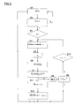
Fig.2 is a flow diagram representing steps in an example method, embodying the invention, for localizing the source of an interfering signal in a passive optical network; -
Fig.3 is a flow diagram representing steps in another example method, embodying the invention, for localizing the source of an interfering signal in a passive optical network; and -
Fig.4 illustrates additional steps that may be taken in an extension of methods such as those ofFigs.2 and3 . - Various methods according to certain embodiments of the invention, and associated devices, will now be described with reference to
Figs.1 to 4 . -
Fig.1 illustrates an example of application of the invention in the context of an FTTH (fiber-to-the-home) PON topology. However, the fact thatFig.1 represents a FTTH topology is purely illustrative; the invention can be applied more generally in substantially any FTTx PON topology to detect which branch in a passive optical network's branching structure is the source of an interfering upstream signal. - The passive
optical network 1 illustrated inFig.1 includes anoptical line terminal 2 connected to a number N ofoptical network terminals 6 via a feederoptical fiber 3, a 1-to-N branching device 4, and N drop fibers 5.The branchingdevice 4 has a first port A on the side towards the OLT and N second ports B on the side towards the ONTs. Which of the ports A and B is considered to be the input or output port of the branchingdevice 4 depends on whether transmission from the OLT to the ONTs is considered or whether transmissions from the ONTs towards the OLT are being considered. - The branching
device 4 illustrated inFig.1 includes first and second active couplers/converters, 41 and 42, having an optical-electrical conversion function and an electrical-optical conversion function. Amanagement system 43 of the branchingdevice 4 applies control logic to ensure appropriate control of theactive converters 41 and 42, for example to implement functions such as power supply, control of coupling, and so on. - A typical value of N in a branching device including active converters used nowadays is 2, 4 or sometimes 8. The present invention does not impose any specific limit on the value of the number N, other than that N is 2 or more, but it may be limited by other practical constraints.
Fig.1 illustrates the case where N=4. - A downstream signal from the OLT towards the ONTs received at port A of the branching
device 4 undergoes optical-electrical conversion at the first active converter 41, any desired processing in the electrical domain, electrical-to-optical conversion at a secondactive converter 42 and output at a port B of the branching device, along with the necessary splitting to N parallel channels. An upstream signal undergoes the inverse of this processing. - The branching
device 4 is configured to exhibit, at its OLT side, behavior similar to that of an ONT, that is, the branchingdevice 4 is configured to have an OMCI channel (ONT Management and Control channel) established with the OLT, to add its own serial number to communications, and may be provisioned in the OLT management system as an ONU/ONT. - In the example illustrated in
Fig.1 , the OLT transmits signals downstream, that is in the direction towards the ONTs, at a wavelength of 1490 nm, and the ONTs reply with signals in the upstream direction at a wavelength of 1310 nm (as in the GPON standard). It should be mentioned that the present invention is not particularly limited having regard to the specific wavelengths used by the OLT and ONTs, the values represented inFig.1 correspond to values employed in various PONs in use today. - In the example illustrated in
Fig.1 , a light source X associated with the connection to the illustratedONT 6 outputs an upstream signal at or in the region of 1310nm and injects the alien (interfering) signal into the network branch 5X via a splitter sp. The upstream signal from source X is received at a port designated BX inFig.4 and the signal is combined with upstream signals from the other ports B and transferred to port A for onward transmission to theOLT 2. The upstream signal from source X tends to cause degradation of the optical transmissions in the upstream direction. The present invention may be applied even when the upstream signal causing signal degradation is emitted by source X at a wavelength different from the standard wavelength for upstream transmissions and irrespective of whether source X emits a continuous, intermittent or modulated signal. -
Fig.1 illustrates aPON 1 in which the branchingdevice 4 is adapted by the addition of adetection unit 10 that is configured to detect interfering upstream signals, notably of the kind involved in DoS attacks on the network. It is to be understood that thedetection unit 10 may be implemented in a variety of ways, depending on the application and the designer's objectives. For example, thedetection unit 10 may be provided as a dedicated software or hardware module, it may be implemented by adjusting the control logic implemented by themanagement system 43, and so on. - The
detection unit 10 is arranged to receive a signal sig1 indicating that interference in the upstream channel has been detected. Typically, sig1 is generated by themanagement system 43 of the branching unit when degradation of the upstream signal at 1310nm is detected at the branching device 4 (management system 43 may be configured to monitor signal quality in an ongoing manner). However, sig1 may be generated in response to detection of signal degradation at the OLT, for example when the OLT generates a "signal degraded" alarm or similar notification. In the latter case the OLT may be configured to send the branching device 4 (or the associated detection unit 10) a direct triggering command directing the branchingdevice 4 to implement a method to localize the source of an interfering upstream signal. However, the OLT may be configured to send the branching device 4 (or detection unit 10) an indirect triggering command in the form of a notification that signal degradation has been detected, and in that case the branchingdevice 4 is configured to respond to the received notification by implementing the source-localization method. Furthermore, the triggering command may be sent by a monitoring module associated with the OLT. - The
detection unit 10 is configured to output a signal sig2 in response to receipt of thesignal sig 1. Signal sig2 controls the second active couplers/converters 42 to switch off the downstream 1490nm signal from the OLT, i.e. to prevent it from reaching the ports B of the branching device.Detection unit 10 is also configured to input measurement signals sig3 indicating the optical power received at each of the ports B of the branching device.Detection unit 10 is also configured to produce a signal sig4 based on its internal processing. Signal sig4 controls a specific one (or, in principle, more than one) second active coupler/converter 42 to prevent a 1310nm signal received from a connected one of the ports B from reaching the port A of the branchingdevice 4. - A method embodying the present invention will now be described with reference to the flow chart of
Fig.2 . The following description is given in the context of implementation of theFig.2 method using the devices illustrated inFig.1 . - In a first step, S1, of the
Fig.2 method, the quality of upstream transmissions in thePON 1 ofFig.1 are monitored. As indicated above, this monitoring may be performed at the branchingdevice 4 or at theOLT 2 or, indeed, in principle at some other location where upstream transmissions in thenetwork 1 can be accessed. During the monitoring, it is verified, in a step S2, whether or not the quality of the upstream signal has degraded to a particular extent. For example, it may be checked whether the bit error rate, frame error rate or the like in an upstream channel has exceeded a threshold that corresponds to a specific absolute or relative degree of signal degradation. If the signal quality is still sufficiently good the flow returns to the monitoring of step S1. On the other hand, if a determined degree of signal degradation has been detected in step S2 then a method is triggered for seeking the network branch that contains the source of an interfering upstream signal (the presumed cause of the signal degradation). In the present example, the detection of signal degradation in step S2 results in production of a triggering signal sig1 that is supplied to thedetection unit 10 ofFig.1 . Thedetection unit 10 manages performance of the source-localization method according to the present embodiment of the invention. - In the specific example illustrated in
Fig.2 , thedetection unit 10 emits control signals sig2 to the secondoptical converters 42 of the branchingdevice 4 one by one, so that the downstream 1460nm signal from the OLT is temporarily cut off from each of the ports B of the branching device. As illustrated inFig.2 , the detection unit selects a first one (j=1) of the secondoptical converters 42 in a step S3, then outputs a control signal sig2 to the selected optical converter so that it prevents the 1490nm downstream signal from reaching the associated port B (step S4 inFig.2 ). At a step S5 of theFig.2 method, a timer (not shown) times a predetermined time period to between the time when the 1490nm downstream signal is interrupted on the selected network branch and a measurement time. - If the duration of the interval t0 is set very short then well-behaved ONTs may not have time to power down their lasers and cease upstream transmissions before measurement is made, leading to a false finding that a network branch containing the relevant ONT is the source of an interfering signal. On the other hand, if the time interval t0 is set long then subscribers using the network may be inconvenienced by the interruption of their connection in step S4 of the method. An implementation of the invention using a time interval t0 of 50 ms duration gives good results, but the invention is not limited to a duration t0 of this specific value and, in particular, shorter or longer time periods may be set, as convenient.
- The
detection unit 10 receives signals indicating the optical power measured at the ports B and, in particular, receives a signal sig3 indicating the optical power measured on the port which is currently cut off from the downstream OLT signals (step S6). After time t0 has elapsed, thedetection unit 10 is configured to compare the power level measured at the relevant port B against a threshold level θ (in step S7 ofFig.2 ). - An example of a suitable threshold power level is -28dBm. This value corresponds to the minimum sensitivity level that is required for an OLT by the ITU-T GPON standard (i.e. the lower limit on the power level of signals, received at the OLT's optical port, which the OLT must be capable of serving correctly). Adopting a θ value that is substantially the same as the minimum sensitivity level of the OLT seeks to ensure that the branching
device 4 behaves similarly to an OLT from the point of view of the users (end ONTs). However, if desired θ may be set to a value different from the minimum sensitivity level of the OLT. - If the measured power at this port B is less than the threshold level θ then it may be inferred that the presently-cut-off port is not connected to the source of the interfering signal, accordingly the connection at this port is restored (step S8), i.e. the relevant second
active coupler 42 allows the downstream 1460nm signal to pass to the relevant drop fiber 5 once again, under control of thedetection unit 10. Thedetection unit 10 is configured to determine whether theoptical coupler 42 that has just been controlled is the last of theoptical couplers 42 to be tested (i.e. is j=jmax), in a step S8. If this is not the lastoptical coupler 42 then theoptical coupler 42 for the next port B is selected (i.e. j is incremented to j+1 in step 9) and steps S4 to S7 are repeated for this next channel. - On the other hand, if in step S7 the measured power at the port B currently under test equals or exceeds the threshold level θ then it may be inferred that the presently-cut-off port is connected to the network branch containing the source of the interfering signal, because a network branch containing only well-behaved ONTs would no longer be propagating a signal in the upstream direction after the downstream signal has been cut off for the time interval t0. Accordingly, in this case the
detection unit 10 identifies the current port under test, in this case BX, as the port connected to the network branch 5X containing the source X of the disturbance on the network (SDIST, in step S10 ofFig.2 ). - As mentioned above, various different types of action may be taken when the source of the interfering signal has been detected by the
detection unit 10, including outputting an alarm signal or notification (not shown in the figures). It is advantageous for thedetection unit 10 to implement a countermeasure against the detected attack automatically. For instance, the detection unit may be configured to output a signal sig4 to the activeoptical coupler 42 connected to the identified network branch containing the source of the interfering upstream signal, so that this active coupler decouples the 1310nm signals received at the connected port B from the OLT side of the branching device 4 (step S11 indicated in dashed lines inFig.2 ). - Although the invention has been described above with reference to certain specific embodiments illustrated in
Figs.1 and2 it is to be understood that the invention is not limited by the details of those specific embodiments; various modifications and improvements can be made without departing from the scope of the invention as defined in the appended claims. - For example, in the flow diagram of
Fig.2 thedetection unit 10 prevents downstream OLT signals from reaching the different network branches by controlling theoptical converters 42 one by one. If desired, thedetection unit 10 can control the secondactive converters 42 to interrupt the downstream OLT signals at all of the ports B simultaneously or, indeed, thedetection unit 10 can control the first active converter 41 to interrupt the downstream signals at port A of the branching device, or the downstream signals may be interrupted at the OLT, or at a point between the OLT and the port A. -
Fig.3 is a flow diagram illustrating an approach in which thedetection unit 10 controls the secondactive converters 42 to interrupt the downstream OLT signals at all of the ports B simultaneously. Steps S31 and S32 ofFig.3 correspond to steps S1 and S2 ofFig.2 . In the subsequent step S33, the downstream signals are cut off from the whole set of ports B simultaneously. In step S34, the timer times the time interval t0 and then, in step S35, power measurements are taken for all of the ports B. In a step S36 the power measurements are checked to identify which power measurement equals or exceeds the threshold θ. In this case, step S36 determines that the network branch 5X connected to the port BX contains a source that is still transmitting upstream with power greater than the threshold level, even in the absence of downstream signals from theOLT 2 and so, in step S37, the network branch 5X connected to port BX is identified as the location of the source of the disturbance of the network (source of the alien signal injection). In step S38 the connections on the other ports are restored so that they start to receive downstream signals from the OLT once again. If desired, the upstream signals from the offending network branch 5X are blocked using theactive converter 42 connected to port BX (step S39 inFig.3 ). -
Fig.4 illustrates certain additional steps that may be implemented in methods according to the present invention to enable, in appropriate cases, the reconnection of network branches that previously have been isolated from the network. The additional steps ofFig.4 will be described in the context of one example of implementation using the apparatus ofFig.1 . - According to the example illustrated in
Fig.4 , after action has been taken (step S41) to prevent signals from a specific network branch, here 5X, from being transmitted to the OLT, the upstream signals coming from this network branch 5X continue to be monitored to see whether the power has fallen below a second threshold level θ2 (step S42). (It will be understood that step S41 inFig.4 corresponds to step S12 inFig.2 and to step S39 inFig.3 ). If the monitoring in step S42 shows that the power level remains too high (greater than θ2) it is inferred that the offending network branch 5X is still propagating an upstream signal that would degrade signal quality in the optical network, and the monitoring continues. On the other hand, if the monitored power level falls below θ2, this is an indication that the network branch 5X is no longer propagating a troublesome upstream signal. Thus, when step S42 results in a positive outcome thedetection unit 10 controls theactive coupler 42 serving the port BX connected to the network branch 5X to allow downstream signals from the OLT to reach this network branch 5X (step S43) and to allow upstream signals from this network branch 5X to be propagated towards the OLT (step S44). - Typically the threshold level θ2, used to decide whether or not the isolated network branch should be re-connected is set the same as the threshold level θ used (e.g. in step S7 of
Fig.2 ) to locate the network branch containing a misbehaving device, for example to -28 dBm. However, this is not essential; threshold level θ2 may be set to a different value from θ, notably it may be set to a lower value so as to ensure that re-connection truly is justified. - If desired, the branching device 4 (more particularly, the detection unit 10) may be configured to send various notifications, to the
OLT 2 or another desired device, for example a notification indicating that a specified network branch has been re-connected following performance of the additional steps represented inFig.4 .
Claims (14)
- A method of identifying the location of a source of an interfering upstream signal in an optical communications network (1) comprising an optical line terminal (OLT) connected to a plurality of optical network terminals (ONTs) via a 1-to-N branching device (4) having a first port (A) connected to the OLT (2) and N second ports (B) connected to N respective network branches (5) extending towards the ONTs (9), the interfering signal propagating in the upstream direction towards the OLT (2), the method comprising the steps of:stopping downstream OLT transmissions from being output from the second ports (B) of the branching device (4),detecting a second port (BX) of the branching device (4) still receiving an upstream signal from the connected network branch (5X) despite the absence of downstream OLT transmissions on said network branch (5X), andidentifying the network branch (5X) connected to the second port (BX) detected in the detecting step as the location of the source (X) of the interfering signal.
- The source-localization method according to claim 1, wherein:the 1-to-N branching device (4) comprises optical-electrical-optical converters (41,42) configured to convert signals received at the branching device (4) from optical form, to electrical form, and back to optical form, andthe stopping step comprises controlling optical-electrical-converters (42) at the ONT side of the branching device (4) to stop downstream OLT transmissions from being output from the second ports (B).
- The source-localization method according to claim 1, and comprising a step of isolating from the OLT (2), at the ONT side of the 1-to-N branching device (4), the network branch (5X) identified in the identifying step.
- The source-localization method according to claim 3, and comprising the steps of:monitoring signals received at the branching device (4) from a network branch (5X) isolated in the isolating step,determining when the network branch (5X) monitored in the monitoring step has stopped transmitting signals in the upstream direction, andre-connecting to the OLT (2) the network branch (5X) determined in the determining step as having stopped upstream transmission.
- The source-localization method according to claim 2, 3 or 4, wherein:the 1-to-N branching device (4) comprises optical-electrical-optical converters (41,42) configured to convert signals received at the branching device (4) from optical form, to electrical form, and back to optical form, andthe isolating step comprises controlling an optical-electrical-converter (42) on the ONT side of the branching device (4) to prevent upstream transmissions from said network branch (5X) identified in the identifying step from reaching the OLT side of the branching device (4).
- The source-localization method according to any previous claim, and comprising the steps of:detecting degradation in optical signal transmission from the ONTs (6) to the OLT (2), andtriggering performance of the stopping, detecting and identifying steps in response to detection of degradation in optical signal transmission in the degradation-detecting step.
- Computer program comprising instructions for performing, when executed by a processor, the source-localization method according to any one of claims 1 to 6.
- A 1-to-N optical branching device (4) comprising :a first port (A) configured for connection to an optical line terminal (OLT),N second ports (B) configured for outputting first optical signals received from the OLT (2) to N respective network branches (5) and for receiving from the network branches (5) optical signals directed to the OLT (2),a first optical converter (41) configured to perform optical-electrical conversion at the first port (A),N second optical converters (42) configured to perform optical-electrical conversion at the N second ports (B), respectively, anda control unit (10) configured to control at least the second optical converters (42);wherein the control unit (10) is configured:to control the optical converters (41/42) to stop downstream OLT transmissions from being output from the second ports (B),to monitor upstream transmissions received from the network branches (5), andto identify, as the location of the source of the interfering signal, a connected network branch (5X) still propagating an upstream transmission despite the absence of downstream OLT transmissions.
- The optical branching device (4) according to claim 8, wherein the control unit (10) is configured to control the second optical converters to interrupt downstream OLT transmissions to the respective connected network branches (5) one by one.
- The optical branching device (4) according to claim 8, wherein the control unit (10) is configured to control the second optical converter (42) connected to the network branch (5X) identified as the source of the interfering signal, to prevent upstream signals transmitted by said network branch (5X) from being transmitted to the OLT (2).
- The optical branching device (4) according to claim 10, wherein the control unit (10) is configured to monitor signals, received at the second optical converter (42) connected to the network branch (5X) identified as the location of the source of the interfering signal, to determine when the connected network branch (5X) has stopped propagating signals in the upstream direction, and to control said second optical converter (42) to re-connect said network branch (5X) to the OLT (2) when the network branch (5X) has stopped transmitting signals in the upstream direction.
- The optical branching device (4) according to any one of claims 8 to 11, wherein the control unit (10) is configured to detect degradation in optical signal transmission from the ONTs (6) to the OLT (2), and to trigger performance of said control, monitoring and identification in response to detection of degradation in optical signal transmission.
- The optical branching device (4) according to any one of claims 8 to 11, wherein the control unit (10) is configured to perform said control, monitoring and identification in response to reception of a notification that degradation has been detected in optical signal transmission from the ONTs (6) to the OLT (2).
- An optical line terminal (OLT) of an optical communications network, the OLT (2) comprising:a connection to one end of an optical fiber (3), the other end of the optical fiber (3) being branched to plural optical network terminals (6) by a remote branching device (4),a receiver unit configured to detect signal degradation in signals received at said connection, anda transmitter unit configured, responsive to detection of signal degradation by the receiver unit, to transmit to the remote branching device (4), via said connection, a triggering command adapted to trigger identification of the source of an interfering signal.
Priority Applications (1)
| Application Number | Priority Date | Filing Date | Title |
|---|---|---|---|
| EP13305917.0A EP2819323B1 (en) | 2013-06-28 | 2013-06-28 | Detection of alien signal injection in passive optical networks |
Applications Claiming Priority (1)
| Application Number | Priority Date | Filing Date | Title |
|---|---|---|---|
| EP13305917.0A EP2819323B1 (en) | 2013-06-28 | 2013-06-28 | Detection of alien signal injection in passive optical networks |
Publications (2)
| Publication Number | Publication Date |
|---|---|
| EP2819323A1 true EP2819323A1 (en) | 2014-12-31 |
| EP2819323B1 EP2819323B1 (en) | 2018-03-07 |
Family
ID=48783163
Family Applications (1)
| Application Number | Title | Priority Date | Filing Date |
|---|---|---|---|
| EP13305917.0A Active EP2819323B1 (en) | 2013-06-28 | 2013-06-28 | Detection of alien signal injection in passive optical networks |
Country Status (1)
| Country | Link |
|---|---|
| EP (1) | EP2819323B1 (en) |
Citations (4)
| Publication number | Priority date | Publication date | Assignee | Title |
|---|---|---|---|---|
| WO2007123692A2 (en) * | 2006-04-05 | 2007-11-01 | Tellabs Petaluma, Inc. | Detecting and minimizing effects of optical network faults |
| WO2007122183A1 (en) * | 2006-04-20 | 2007-11-01 | Nokia Siemens Networks Gmbh & Co. Kg | Protection device for removal of signal interference in a passive optical network |
| US20080095532A1 (en) * | 2006-10-19 | 2008-04-24 | Fujitsu Limited | Techique of identifying a defective subscriber device in a point-to-multipoint network without stopping normal subscriber devices |
| US20120163808A1 (en) * | 2010-12-23 | 2012-06-28 | Electronics And Telecommunications Research Institute | Detecting rogue onu, olt and pon system |
-
2013
- 2013-06-28 EP EP13305917.0A patent/EP2819323B1/en active Active
Patent Citations (4)
| Publication number | Priority date | Publication date | Assignee | Title |
|---|---|---|---|---|
| WO2007123692A2 (en) * | 2006-04-05 | 2007-11-01 | Tellabs Petaluma, Inc. | Detecting and minimizing effects of optical network faults |
| WO2007122183A1 (en) * | 2006-04-20 | 2007-11-01 | Nokia Siemens Networks Gmbh & Co. Kg | Protection device for removal of signal interference in a passive optical network |
| US20080095532A1 (en) * | 2006-10-19 | 2008-04-24 | Fujitsu Limited | Techique of identifying a defective subscriber device in a point-to-multipoint network without stopping normal subscriber devices |
| US20120163808A1 (en) * | 2010-12-23 | 2012-06-28 | Electronics And Telecommunications Research Institute | Detecting rogue onu, olt and pon system |
Also Published As
| Publication number | Publication date |
|---|---|
| EP2819323B1 (en) | 2018-03-07 |
Similar Documents
| Publication | Publication Date | Title |
|---|---|---|
| US8682163B2 (en) | Detecting method, apparatus, and system in an optical distribution network | |
| US8768163B2 (en) | Detecting rogue ONU, OLT and PON system | |
| US6534997B1 (en) | Apparatus and a method for locating a fault of a transmission line | |
| US9008503B2 (en) | Supervision of wavelength division multiplexed optical networks | |
| US9673895B2 (en) | PON supervision using OTDR measurements | |
| US8774623B2 (en) | Passive optical network system and method for detecting fault in optical network terminal | |
| US20150326311A1 (en) | Rogue optical network interface device detection | |
| US9344188B2 (en) | Device, remote node and methods for PON supervision | |
| KR20120050960A (en) | Passive optical netwok(pon) in-band optical time domain peflectometer(otdr) | |
| US11070295B2 (en) | PON system, optical network unit, optical line terminal, method of registering optical network unit, and data structure | |
| WO2013147655A1 (en) | An arrangement at a remote node, a remote node, a central office and respective methods therein for supervision of a wavelength division multiplexed passive optical network | |
| JP2006180475A (en) | Passive optical network monitoring method and passive optical network | |
| KR20140011544A (en) | Method for detecting and removing error ont | |
| KR102657364B1 (en) | Method, apparatus and system for determining connectivity of optical network terminals | |
| WO2013082771A1 (en) | Optical fiber link detection method, optical line terminal, and passive optical network system | |
| JP2012029176A (en) | Hinderance onu specification device, hinderance onu specification method and pon system | |
| JP2011035738A (en) | Fault ONU identification method and apparatus | |
| EP2819323B1 (en) | Detection of alien signal injection in passive optical networks | |
| KR101484267B1 (en) | Optical Network Termination with detect error, reset, power off, and storing the information | |
| KR100952875B1 (en) | Optical network terminator and optical transmitting end control method in the apparatus | |
| US8463139B2 (en) | Transmitter disabling device | |
| JP2012173184A (en) | Optical multiple reflection point specifying device and method | |
| JP2017011379A (en) | PON system | |
| KR102692596B1 (en) | System and method for blocking unauthorized line in passive optical network | |
| JP2012151737A (en) | Station side optical network terminal device, optical communication system, abnormality detection method, and device program |
Legal Events
| Date | Code | Title | Description |
|---|---|---|---|
| PUAI | Public reference made under article 153(3) epc to a published international application that has entered the european phase |
Free format text: ORIGINAL CODE: 0009012 |
|
| 17P | Request for examination filed |
Effective date: 20130628 |
|
| AK | Designated contracting states |
Kind code of ref document: A1 Designated state(s): AL AT BE BG CH CY CZ DE DK EE ES FI FR GB GR HR HU IE IS IT LI LT LU LV MC MK MT NL NO PL PT RO RS SE SI SK SM TR |
|
| AX | Request for extension of the european patent |
Extension state: BA ME |
|
| R17P | Request for examination filed (corrected) |
Effective date: 20150629 |
|
| RBV | Designated contracting states (corrected) |
Designated state(s): AL AT BE BG CH CY CZ DE DK EE ES FI FR GB GR HR HU IE IS IT LI LT LU LV MC MK MT NL NO PL PT RO RS SE SI SK SM TR |
|
| GRAP | Despatch of communication of intention to grant a patent |
Free format text: ORIGINAL CODE: EPIDOSNIGR1 |
|
| INTG | Intention to grant announced |
Effective date: 20171004 |
|
| GRAS | Grant fee paid |
Free format text: ORIGINAL CODE: EPIDOSNIGR3 |
|
| GRAA | (expected) grant |
Free format text: ORIGINAL CODE: 0009210 |
|
| AK | Designated contracting states |
Kind code of ref document: B1 Designated state(s): AL AT BE BG CH CY CZ DE DK EE ES FI FR GB GR HR HU IE IS IT LI LT LU LV MC MK MT NL NO PL PT RO RS SE SI SK SM TR |
|
| REG | Reference to a national code |
Ref country code: GB Ref legal event code: FG4D |
|
| REG | Reference to a national code |
Ref country code: CH Ref legal event code: EP Ref country code: AT Ref legal event code: REF Ref document number: 977623 Country of ref document: AT Kind code of ref document: T Effective date: 20180315 |
|
| REG | Reference to a national code |
Ref country code: IE Ref legal event code: FG4D |
|
| REG | Reference to a national code |
Ref country code: DE Ref legal event code: R096 Ref document number: 602013033976 Country of ref document: DE |
|
| REG | Reference to a national code |
Ref country code: FR Ref legal event code: PLFP Year of fee payment: 6 |
|
| REG | Reference to a national code |
Ref country code: NL Ref legal event code: MP Effective date: 20180307 |
|
| REG | Reference to a national code |
Ref country code: LT Ref legal event code: MG4D |
|
| PG25 | Lapsed in a contracting state [announced via postgrant information from national office to epo] |
Ref country code: ES Free format text: LAPSE BECAUSE OF FAILURE TO SUBMIT A TRANSLATION OF THE DESCRIPTION OR TO PAY THE FEE WITHIN THE PRESCRIBED TIME-LIMIT Effective date: 20180307 Ref country code: CY Free format text: LAPSE BECAUSE OF FAILURE TO SUBMIT A TRANSLATION OF THE DESCRIPTION OR TO PAY THE FEE WITHIN THE PRESCRIBED TIME-LIMIT Effective date: 20180307 Ref country code: LT Free format text: LAPSE BECAUSE OF FAILURE TO SUBMIT A TRANSLATION OF THE DESCRIPTION OR TO PAY THE FEE WITHIN THE PRESCRIBED TIME-LIMIT Effective date: 20180307 Ref country code: HR Free format text: LAPSE BECAUSE OF FAILURE TO SUBMIT A TRANSLATION OF THE DESCRIPTION OR TO PAY THE FEE WITHIN THE PRESCRIBED TIME-LIMIT Effective date: 20180307 Ref country code: FI Free format text: LAPSE BECAUSE OF FAILURE TO SUBMIT A TRANSLATION OF THE DESCRIPTION OR TO PAY THE FEE WITHIN THE PRESCRIBED TIME-LIMIT Effective date: 20180307 Ref country code: NO Free format text: LAPSE BECAUSE OF FAILURE TO SUBMIT A TRANSLATION OF THE DESCRIPTION OR TO PAY THE FEE WITHIN THE PRESCRIBED TIME-LIMIT Effective date: 20180607 |
|
| REG | Reference to a national code |
Ref country code: AT Ref legal event code: MK05 Ref document number: 977623 Country of ref document: AT Kind code of ref document: T Effective date: 20180307 |
|
| PG25 | Lapsed in a contracting state [announced via postgrant information from national office to epo] |
Ref country code: BG Free format text: LAPSE BECAUSE OF FAILURE TO SUBMIT A TRANSLATION OF THE DESCRIPTION OR TO PAY THE FEE WITHIN THE PRESCRIBED TIME-LIMIT Effective date: 20180607 Ref country code: SE Free format text: LAPSE BECAUSE OF FAILURE TO SUBMIT A TRANSLATION OF THE DESCRIPTION OR TO PAY THE FEE WITHIN THE PRESCRIBED TIME-LIMIT Effective date: 20180307 Ref country code: RS Free format text: LAPSE BECAUSE OF FAILURE TO SUBMIT A TRANSLATION OF THE DESCRIPTION OR TO PAY THE FEE WITHIN THE PRESCRIBED TIME-LIMIT Effective date: 20180307 Ref country code: GR Free format text: LAPSE BECAUSE OF FAILURE TO SUBMIT A TRANSLATION OF THE DESCRIPTION OR TO PAY THE FEE WITHIN THE PRESCRIBED TIME-LIMIT Effective date: 20180608 Ref country code: LV Free format text: LAPSE BECAUSE OF FAILURE TO SUBMIT A TRANSLATION OF THE DESCRIPTION OR TO PAY THE FEE WITHIN THE PRESCRIBED TIME-LIMIT Effective date: 20180307 |
|
| PG25 | Lapsed in a contracting state [announced via postgrant information from national office to epo] |
Ref country code: EE Free format text: LAPSE BECAUSE OF FAILURE TO SUBMIT A TRANSLATION OF THE DESCRIPTION OR TO PAY THE FEE WITHIN THE PRESCRIBED TIME-LIMIT Effective date: 20180307 Ref country code: NL Free format text: LAPSE BECAUSE OF FAILURE TO SUBMIT A TRANSLATION OF THE DESCRIPTION OR TO PAY THE FEE WITHIN THE PRESCRIBED TIME-LIMIT Effective date: 20180307 Ref country code: RO Free format text: LAPSE BECAUSE OF FAILURE TO SUBMIT A TRANSLATION OF THE DESCRIPTION OR TO PAY THE FEE WITHIN THE PRESCRIBED TIME-LIMIT Effective date: 20180307 Ref country code: PL Free format text: LAPSE BECAUSE OF FAILURE TO SUBMIT A TRANSLATION OF THE DESCRIPTION OR TO PAY THE FEE WITHIN THE PRESCRIBED TIME-LIMIT Effective date: 20180307 Ref country code: AL Free format text: LAPSE BECAUSE OF FAILURE TO SUBMIT A TRANSLATION OF THE DESCRIPTION OR TO PAY THE FEE WITHIN THE PRESCRIBED TIME-LIMIT Effective date: 20180307 Ref country code: IT Free format text: LAPSE BECAUSE OF FAILURE TO SUBMIT A TRANSLATION OF THE DESCRIPTION OR TO PAY THE FEE WITHIN THE PRESCRIBED TIME-LIMIT Effective date: 20180307 |
|
| PG25 | Lapsed in a contracting state [announced via postgrant information from national office to epo] |
Ref country code: SM Free format text: LAPSE BECAUSE OF FAILURE TO SUBMIT A TRANSLATION OF THE DESCRIPTION OR TO PAY THE FEE WITHIN THE PRESCRIBED TIME-LIMIT Effective date: 20180307 Ref country code: AT Free format text: LAPSE BECAUSE OF FAILURE TO SUBMIT A TRANSLATION OF THE DESCRIPTION OR TO PAY THE FEE WITHIN THE PRESCRIBED TIME-LIMIT Effective date: 20180307 Ref country code: SK Free format text: LAPSE BECAUSE OF FAILURE TO SUBMIT A TRANSLATION OF THE DESCRIPTION OR TO PAY THE FEE WITHIN THE PRESCRIBED TIME-LIMIT Effective date: 20180307 Ref country code: CZ Free format text: LAPSE BECAUSE OF FAILURE TO SUBMIT A TRANSLATION OF THE DESCRIPTION OR TO PAY THE FEE WITHIN THE PRESCRIBED TIME-LIMIT Effective date: 20180307 |
|
| REG | Reference to a national code |
Ref country code: DE Ref legal event code: R097 Ref document number: 602013033976 Country of ref document: DE |
|
| PG25 | Lapsed in a contracting state [announced via postgrant information from national office to epo] |
Ref country code: PT Free format text: LAPSE BECAUSE OF FAILURE TO SUBMIT A TRANSLATION OF THE DESCRIPTION OR TO PAY THE FEE WITHIN THE PRESCRIBED TIME-LIMIT Effective date: 20180709 |
|
| PLBE | No opposition filed within time limit |
Free format text: ORIGINAL CODE: 0009261 |
|
| STAA | Information on the status of an ep patent application or granted ep patent |
Free format text: STATUS: NO OPPOSITION FILED WITHIN TIME LIMIT |
|
| PG25 | Lapsed in a contracting state [announced via postgrant information from national office to epo] |
Ref country code: DK Free format text: LAPSE BECAUSE OF FAILURE TO SUBMIT A TRANSLATION OF THE DESCRIPTION OR TO PAY THE FEE WITHIN THE PRESCRIBED TIME-LIMIT Effective date: 20180307 |
|
| REG | Reference to a national code |
Ref country code: CH Ref legal event code: PL |
|
| 26N | No opposition filed |
Effective date: 20181210 |
|
| PG25 | Lapsed in a contracting state [announced via postgrant information from national office to epo] |
Ref country code: SI Free format text: LAPSE BECAUSE OF FAILURE TO SUBMIT A TRANSLATION OF THE DESCRIPTION OR TO PAY THE FEE WITHIN THE PRESCRIBED TIME-LIMIT Effective date: 20180307 |
|
| REG | Reference to a national code |
Ref country code: BE Ref legal event code: MM Effective date: 20180630 |
|
| PG25 | Lapsed in a contracting state [announced via postgrant information from national office to epo] |
Ref country code: MC Free format text: LAPSE BECAUSE OF FAILURE TO SUBMIT A TRANSLATION OF THE DESCRIPTION OR TO PAY THE FEE WITHIN THE PRESCRIBED TIME-LIMIT Effective date: 20180307 Ref country code: LU Free format text: LAPSE BECAUSE OF NON-PAYMENT OF DUE FEES Effective date: 20180628 |
|
| REG | Reference to a national code |
Ref country code: IE Ref legal event code: MM4A |
|
| PG25 | Lapsed in a contracting state [announced via postgrant information from national office to epo] |
Ref country code: LI Free format text: LAPSE BECAUSE OF NON-PAYMENT OF DUE FEES Effective date: 20180630 Ref country code: IE Free format text: LAPSE BECAUSE OF NON-PAYMENT OF DUE FEES Effective date: 20180628 Ref country code: CH Free format text: LAPSE BECAUSE OF NON-PAYMENT OF DUE FEES Effective date: 20180630 |
|
| PG25 | Lapsed in a contracting state [announced via postgrant information from national office to epo] |
Ref country code: BE Free format text: LAPSE BECAUSE OF NON-PAYMENT OF DUE FEES Effective date: 20180630 |
|
| PG25 | Lapsed in a contracting state [announced via postgrant information from national office to epo] |
Ref country code: MT Free format text: LAPSE BECAUSE OF NON-PAYMENT OF DUE FEES Effective date: 20180628 |
|
| PG25 | Lapsed in a contracting state [announced via postgrant information from national office to epo] |
Ref country code: TR Free format text: LAPSE BECAUSE OF FAILURE TO SUBMIT A TRANSLATION OF THE DESCRIPTION OR TO PAY THE FEE WITHIN THE PRESCRIBED TIME-LIMIT Effective date: 20180307 |
|
| PG25 | Lapsed in a contracting state [announced via postgrant information from national office to epo] |
Ref country code: HU Free format text: LAPSE BECAUSE OF FAILURE TO SUBMIT A TRANSLATION OF THE DESCRIPTION OR TO PAY THE FEE WITHIN THE PRESCRIBED TIME-LIMIT; INVALID AB INITIO Effective date: 20130628 |
|
| PG25 | Lapsed in a contracting state [announced via postgrant information from national office to epo] |
Ref country code: MK Free format text: LAPSE BECAUSE OF NON-PAYMENT OF DUE FEES Effective date: 20180307 |
|
| PG25 | Lapsed in a contracting state [announced via postgrant information from national office to epo] |
Ref country code: IS Free format text: LAPSE BECAUSE OF FAILURE TO SUBMIT A TRANSLATION OF THE DESCRIPTION OR TO PAY THE FEE WITHIN THE PRESCRIBED TIME-LIMIT Effective date: 20180707 |
|
| PGFP | Annual fee paid to national office [announced via postgrant information from national office to epo] |
Ref country code: DE Payment date: 20250520 Year of fee payment: 13 |
|
| PGFP | Annual fee paid to national office [announced via postgrant information from national office to epo] |
Ref country code: GB Payment date: 20250520 Year of fee payment: 13 |
|
| PGFP | Annual fee paid to national office [announced via postgrant information from national office to epo] |
Ref country code: FR Payment date: 20250520 Year of fee payment: 13 |