EP2819222A1 - Positive-electrode active material for non-aqueous secondary battery and method for producing the same - Google Patents
Positive-electrode active material for non-aqueous secondary battery and method for producing the same Download PDFInfo
- Publication number
- EP2819222A1 EP2819222A1 EP14174752.7A EP14174752A EP2819222A1 EP 2819222 A1 EP2819222 A1 EP 2819222A1 EP 14174752 A EP14174752 A EP 14174752A EP 2819222 A1 EP2819222 A1 EP 2819222A1
- Authority
- EP
- European Patent Office
- Prior art keywords
- positive
- transition metal
- electrode active
- precipitate
- active material
- Prior art date
- Legal status (The legal status is an assumption and is not a legal conclusion. Google has not performed a legal analysis and makes no representation as to the accuracy of the status listed.)
- Granted
Links
Images

Classifications
-
- H—ELECTRICITY
- H01—ELECTRIC ELEMENTS
- H01M—PROCESSES OR MEANS, e.g. BATTERIES, FOR THE DIRECT CONVERSION OF CHEMICAL ENERGY INTO ELECTRICAL ENERGY
- H01M4/00—Electrodes
- H01M4/02—Electrodes composed of, or comprising, active material
- H01M4/36—Selection of substances as active materials, active masses, active liquids
- H01M4/48—Selection of substances as active materials, active masses, active liquids of inorganic oxides or hydroxides
- H01M4/52—Selection of substances as active materials, active masses, active liquids of inorganic oxides or hydroxides of nickel, cobalt or iron
- H01M4/525—Selection of substances as active materials, active masses, active liquids of inorganic oxides or hydroxides of nickel, cobalt or iron of mixed oxides or hydroxides containing iron, cobalt or nickel for inserting or intercalating light metals, e.g. LiNiO2, LiCoO2 or LiCoOxFy
-
- C—CHEMISTRY; METALLURGY
- C01—INORGANIC CHEMISTRY
- C01G—COMPOUNDS CONTAINING METALS NOT COVERED BY SUBCLASSES C01D OR C01F
- C01G45/00—Compounds of manganese
- C01G45/12—Complex oxides containing manganese and at least one other metal element
- C01G45/1221—Manganates or manganites with trivalent manganese, tetravalent manganese or mixtures thereof
- C01G45/1228—Manganates or manganites with trivalent manganese, tetravalent manganese or mixtures thereof of the type (MnO2)-, e.g. LiMnO2 or Li(MxMn1-x)O2
-
- C—CHEMISTRY; METALLURGY
- C01—INORGANIC CHEMISTRY
- C01G—COMPOUNDS CONTAINING METALS NOT COVERED BY SUBCLASSES C01D OR C01F
- C01G45/00—Compounds of manganese
- C01G45/20—Compounds containing manganese, with or without oxygen or hydrogen, and containing one or more other elements
- C01G45/22—Compounds containing manganese, with or without oxygen or hydrogen, and containing two or more other elements
-
- C—CHEMISTRY; METALLURGY
- C01—INORGANIC CHEMISTRY
- C01G—COMPOUNDS CONTAINING METALS NOT COVERED BY SUBCLASSES C01D OR C01F
- C01G49/00—Compounds of iron
- C01G49/0018—Mixed oxides or hydroxides
-
- C—CHEMISTRY; METALLURGY
- C01—INORGANIC CHEMISTRY
- C01G—COMPOUNDS CONTAINING METALS NOT COVERED BY SUBCLASSES C01D OR C01F
- C01G49/00—Compounds of iron
- C01G49/009—Compounds containing iron, with or without oxygen or hydrogen, and containing two or more other elements
-
- C—CHEMISTRY; METALLURGY
- C01—INORGANIC CHEMISTRY
- C01G—COMPOUNDS CONTAINING METALS NOT COVERED BY SUBCLASSES C01D OR C01F
- C01G51/00—Compounds of cobalt
- C01G51/40—Complex oxides containing cobalt and at least one other metal element
- C01G51/42—Complex oxides containing cobalt and at least one other metal element containing alkali metals, e.g. LiCoO2
-
- C—CHEMISTRY; METALLURGY
- C01—INORGANIC CHEMISTRY
- C01G—COMPOUNDS CONTAINING METALS NOT COVERED BY SUBCLASSES C01D OR C01F
- C01G51/00—Compounds of cobalt
- C01G51/80—Compounds containing cobalt, with or without oxygen or hydrogen, and containing one or more other elements
- C01G51/82—Compounds containing cobalt, with or without oxygen or hydrogen, and containing two or more other elements
-
- C—CHEMISTRY; METALLURGY
- C01—INORGANIC CHEMISTRY
- C01G—COMPOUNDS CONTAINING METALS NOT COVERED BY SUBCLASSES C01D OR C01F
- C01G53/00—Compounds of nickel
- C01G53/40—Complex oxides containing nickel and at least one other metal element
- C01G53/42—Complex oxides containing nickel and at least one other metal element containing alkali metals, e.g. LiNiO2
-
- C—CHEMISTRY; METALLURGY
- C01—INORGANIC CHEMISTRY
- C01G—COMPOUNDS CONTAINING METALS NOT COVERED BY SUBCLASSES C01D OR C01F
- C01G53/00—Compounds of nickel
- C01G53/80—Compounds containing nickel, with or without oxygen or hydrogen, and containing one or more other elements
- C01G53/82—Compounds containing nickel, with or without oxygen or hydrogen, and containing two or more other elements
-
- H—ELECTRICITY
- H01—ELECTRIC ELEMENTS
- H01M—PROCESSES OR MEANS, e.g. BATTERIES, FOR THE DIRECT CONVERSION OF CHEMICAL ENERGY INTO ELECTRICAL ENERGY
- H01M10/00—Secondary cells; Manufacture thereof
- H01M10/05—Accumulators with non-aqueous electrolyte
- H01M10/054—Accumulators with insertion or intercalation of metals other than lithium, e.g. with magnesium or aluminium
-
- C—CHEMISTRY; METALLURGY
- C01—INORGANIC CHEMISTRY
- C01P—INDEXING SCHEME RELATING TO STRUCTURAL AND PHYSICAL ASPECTS OF SOLID INORGANIC COMPOUNDS
- C01P2002/00—Crystal-structural characteristics
- C01P2002/70—Crystal-structural characteristics defined by measured X-ray, neutron or electron diffraction data
- C01P2002/72—Crystal-structural characteristics defined by measured X-ray, neutron or electron diffraction data by d-values or two theta-values, e.g. as X-ray diagram
-
- C—CHEMISTRY; METALLURGY
- C01—INORGANIC CHEMISTRY
- C01P—INDEXING SCHEME RELATING TO STRUCTURAL AND PHYSICAL ASPECTS OF SOLID INORGANIC COMPOUNDS
- C01P2002/00—Crystal-structural characteristics
- C01P2002/70—Crystal-structural characteristics defined by measured X-ray, neutron or electron diffraction data
- C01P2002/76—Crystal-structural characteristics defined by measured X-ray, neutron or electron diffraction data by a space-group or by other symmetry indications
-
- C—CHEMISTRY; METALLURGY
- C01—INORGANIC CHEMISTRY
- C01P—INDEXING SCHEME RELATING TO STRUCTURAL AND PHYSICAL ASPECTS OF SOLID INORGANIC COMPOUNDS
- C01P2006/00—Physical properties of inorganic compounds
- C01P2006/40—Electric properties
-
- H—ELECTRICITY
- H01—ELECTRIC ELEMENTS
- H01M—PROCESSES OR MEANS, e.g. BATTERIES, FOR THE DIRECT CONVERSION OF CHEMICAL ENERGY INTO ELECTRICAL ENERGY
- H01M4/00—Electrodes
- H01M4/02—Electrodes composed of, or comprising, active material
- H01M4/36—Selection of substances as active materials, active masses, active liquids
- H01M4/48—Selection of substances as active materials, active masses, active liquids of inorganic oxides or hydroxides
- H01M4/50—Selection of substances as active materials, active masses, active liquids of inorganic oxides or hydroxides of manganese
- H01M4/505—Selection of substances as active materials, active masses, active liquids of inorganic oxides or hydroxides of manganese of mixed oxides or hydroxides containing manganese for inserting or intercalating light metals, e.g. LiMn2O4 or LiMn2OxFy
-
- Y—GENERAL TAGGING OF NEW TECHNOLOGICAL DEVELOPMENTS; GENERAL TAGGING OF CROSS-SECTIONAL TECHNOLOGIES SPANNING OVER SEVERAL SECTIONS OF THE IPC; TECHNICAL SUBJECTS COVERED BY FORMER USPC CROSS-REFERENCE ART COLLECTIONS [XRACs] AND DIGESTS
- Y02—TECHNOLOGIES OR APPLICATIONS FOR MITIGATION OR ADAPTATION AGAINST CLIMATE CHANGE
- Y02E—REDUCTION OF GREENHOUSE GAS [GHG] EMISSIONS, RELATED TO ENERGY GENERATION, TRANSMISSION OR DISTRIBUTION
- Y02E60/00—Enabling technologies; Technologies with a potential or indirect contribution to GHG emissions mitigation
- Y02E60/10—Energy storage using batteries
Definitions
- the present invention relates to positive-electrode active materials for non-aqueous secondary batteries such as sodium ion secondary batteries, and to methods for producing the same.
- non-aqueous secondary batteries typically lithium ion secondary batteries
- Lithium ion secondary batteries have as high an operating voltage as about 4 V and can store large amounts of energy per unit mass. Due to these advantages, their application to large apparatuses such as electric vehicles and power storage systems has been expected.
- lithium transition metal composite oxides such as lithium cobaltate are typically used as the positive-electrode active materials.
- lithium and transition metals such as cobalt are rare or precious elements due to reasons such as that the reserves of these elements are unevenly distributed and also that such elements are obtained by separation as impurities from materials such as minerals.
- sodium transition metal composite oxides having a layered structure based on abundant elements such as iron and sodium be used as the positive-electrode active materials.
- Sodium ion secondary batteries involving such positive-electrode active materials have been also proposed.
- JP 2005-317511A discloses composite oxides represented by NaFe 1-x M x O 2 , wherein M is a trivalent metal element and 0 ⁇ x ⁇ 0.5.
- the disclosure describes production methods involving Na 2 O 2 and Fe 3 O 4 as examples of a sodium compound and an iron compound that are raw materials.
- JP 2009-135092A discloses composite metal oxides with a layered rock salt structure represented by Formula Na x Fe 1-y M y O 2 , wherein M is an element such as Mn, 0.5 ⁇ x ⁇ 1 and 0 ⁇ y ⁇ 0.5. According to the disclosure, the above range of x ensures that the layered rock salt crystal structure will have high purity and more sodium ions are available for doping and dedoping.
- the disclosure also describes production methods involving Na 2 CO 3 , Fe 3 O 4 and MnO 2 as examples of a sodium compound, an iron compound and a manganese compound that are raw materials.
- WO 2012/060295 discloses composite metal oxides including a P2 structure oxide and a layered oxide that are represented by Formula Na x Fe y Mn 1-y O 2 , wherein 2/3 ⁇ x ⁇ 1 and 0 ⁇ y ⁇ 2/3.
- the disclosure describes production methods involving Na 2 CO 3 , NaHCO 3 , Na 2 O 2 , Fe 3 O 4 and MnO 2 as examples of sodium compounds, an iron compound and a manganese compound that are raw materials.
- the composite metal oxides described in JP 2009-135092A and WO 2012/060295 have an R-3m crystal structure when the sodium to transition metal ratio is 1, but the layered structure comes to take a P6 3 /mmc crystal structure when the ratio is less than 1.
- the P6 3 /mmc structure is more resistant to breakage by the desorption and insertion of sodium ions than the R-3m structure, and this fact makes the P6 3 /mmc crystal structure advantageous in terms of charge and discharge characteristics at a high stage of charge (SOC).
- Patent Literatures JP 2009-135092A and WO 2012/060295 mention that a mixture of metal-containing compounds with a prescribed chemical composition may be obtained by a crystallization method, the specifications do not teach any specific conditions in the production methods or whatsoever.
- the methods disclosed in Patent Literatures JP 2005-317511A , JP 2009-135092A and WO 2012/060295 involve the calcination of a raw material mixture produced by a so-called dry process.
- sodium transition metal composite oxides obtained by such methods contain subphases which have crystal structures different from the desired structure.
- the target crystal structure is P6 3 /mmc
- subphases such as R-3m structure, Pnma structure and Fd-3m structure occur. The occurrence of such subphases is probably ascribed to the elements in the raw material mixture being mixed with insufficient uniformity.
- transition metal elements may be effected to sufficient uniformity by a so-called coprecipitation process in which transition metal ions are precipitated by pH control or with an agent such as a complexing agent.
- counter ions for the transition metal ions for example, nitrate ions in the case of an aqueous transition metal nitrate salt solution, are often incorporated into the crystal or the precipitate aggregate during precipitation. Such counter ions that have been incorporated can adversely affect the performance of non-aqueous secondary batteries. Thus, the best performance of sodium ion secondary batteries cannot be achieved by the simple application of a coprecipitation process.
- An object of the invention is to provide methods for producing positive-electrode active materials for non-aqueous secondary battery which have a high purity of P6 3 /mmc structure and allow non-aqueous sodium secondary batteries such as sodium ion secondary batteries to fully exhibit their performance.
- Another object of the invention is to provide positive-electrode active materials for non-aqueous sodium secondary batteries which are satisfactory both in charge-discharge capacity and cycle characteristics and in other properties.
- a sodium transition metal composite oxide which is substantially composed of P6 3 /mmc alone and has a very low content of counter ions may be obtained by a process in which a transition metal composite compound as a precursor is prepared by a coprecipitation method including specific steps, the precursor is then mixed with other raw material compounds, and the mixture is calcined.
- an aspect of the present invention provides a positive-electrode active material for non-aqueous secondary battery of the invention includes a sodium transition metal composite oxide that is represented by Formula Na x Fe 1-y MyO 2 wherein 0.4 ⁇ x ⁇ 0.7, 0.25 ⁇ y ⁇ 1.0, and M is at least one element selected from the group consisting of manganese, cobalt and nickel and has a crystal structure substantially composed of P6 3 /mmc alone.
- a first aspect of a method for producing a positive-electrode active material for non-aqueous secondary battery of the invention resides in a method for producing, the positive-electrode active material for non-aqueous secondary battery including a sodium transition metal composite oxide represented by Formula Na x Fe 1-y M y O 2 , wherein 0.4 ⁇ x ⁇ 0.7, 0.25 ⁇ y ⁇ 1.0, and M is at least one element selected from the group consisting of manganese, cobalt and nickel, the method comprising a precipitate formation step of obtaining a precipitate of a transition metal composite compound from a transition metal ion-containing aqueous solution, a heat treatment step of heat treating the precipitate from the precipitate formation step to obtain a transition metal composite oxide precursor, a mixing step of mixing the precursor from the heat treatment step with at least a sodium compound to obtain a raw material mixture, and a calcination step of calcining the raw material mixture from the mixing step to obtain a calcined product.
- a second aspect of a method for producing a positive-electrode active material for non-aqueous secondary battery of the invention resides in a method for producing the positive-electrode active material for non-aqueous secondary battery including a sodium transition metal composite oxide represented by Formula Na x Fe 1-y M y O 2 , wherein 0.4 ⁇ x ⁇ 0.7, 0.25 ⁇ y ⁇ 1.0, and M is at least one element selected from the group consisting of manganese, cobalt and nickel, the method comprising a precipitate formation step of obtaining a precipitate of a transition metal composite compound other than a hydroxide from a transition metal ion-containing aqueous solution, a mixing step of mixing the precipitate from the precipitate formation step with at least a sodium compound to obtain a raw material mixture, and a calcination step of calcining the raw material mixture from the mixing step to obtain a calcined product.
- a precipitate formation step of obtaining a precipitate of a transition
- the inventive methods for the production of positive-electrode active materials for non-aqueous secondary battery can produce sodium transition metal composite oxides which are substantially composed of a P6 3 /mmc structure alone and have a sufficiently low content of counter ions contained in the oxide.
- the inventive positive-electrode active material for non-aqueous secondary battery allows a battery to achieve advantageous charge-discharge capacity and cycle characteristics due to the P6 3 /mmc structure and also to perform well in other battery characteristics.
- step encompasses not only an independent step but also a step in which the anticipated effect of this step is achieved, even if the step cannot be clearly distinguished from another step.
- the content of each ingredient of the composition denotes the total amount of the plural materials included in the composition.
- a first embodiment of the present invention is a positive-electrode active material for non-aqueous secondary battery comprising a sodium transition metal composite oxide that is represented by Formula Na x Fe 1-y M y O 2 , wherein 0.4 ⁇ x ⁇ 0.7, 0.25 ⁇ y ⁇ 1.0, and M is at least one element selected from the group consisting of manganese, cobalt and nickel and having a crystal structure substantially composed of P6 3 /mmc alone.
- the positive-electrode active material is satisfactory both in charge-discharge capacity and cycle characteristics and in other properties.
- a second embodiment is a method for producing a positive-electrode active material for non-aqueous secondary battery comprising a sodium transition metal composite oxide represented by Formula Na x Fe 1-y M y O 2 , wherein 0.4 ⁇ x ⁇ 0.7, 0.25 ⁇ y ⁇ 1.0, and M is at least one element selected from the group consisting of manganese, cobalt and nickel, comprising a precipitate formation step of obtaining a precipitate of a transition metal composite compound from a transition metal ion-containing aqueous solution, a heat treatment step of heat treating the precipitate from the precipitate formation step to obtain a transition metal composite oxide precursor, a mixing step of mixing the precursor from the heat treatment step with at least a sodium compound to obtain a raw material mixture, and a calcination step of calcining the raw material mixture from the mixing step to obtain a calcined product.
- a precipitate formation step of obtaining a precipitate of a transition metal composite compound from a transition metal ion
- a third embodiment is a method for producing a positive-electrode active material for non-aqueous secondary battery comprising a sodium transition metal composite oxide represented by Formula Na x Fe 1-y M y O 2 , wherein 0.4 ⁇ x ⁇ 0.7, 0.25 ⁇ y ⁇ 1.0, and M is at least one element selected from the group consisting of manganese, cobalt and nickel, comprising a precipitate formation step of obtaining a precipitate of a transition metal composite compound other than a hydroxide from a transition metal ion-containing aqueous solution, a mixing step of mixing the precipitate from the precipitate formation step with at least a sodium compound to obtain a raw material mixture, and a calcination step of calcining the raw material mixture from the mixing step to obtain a calcined product.
- a precipitate formation step of obtaining a precipitate of a transition metal composite compound other than a hydroxide from a transition metal ion-containing aqueous solution
- positive-electrode active materials for non-aqueous secondary battery hereinafter, also written simply as "positive-electrode active materials", according to the present invention will be discussed in detail.
- the positive-electrode active material for non-aqueous secondary battery of the invention includes a sodium transition metal composite oxide that is represented by Formula Na x Fe 1-y M y O 2 , wherein 0.4 ⁇ x ⁇ 0.7, 0.25 ⁇ y ⁇ 1.0, and M is at least one element selected from the group consisting of manganese, cobalt and nickel and has a crystal structure substantially composed of P6 3 /mmc alone.
- the presence of a P6 3 /mmc structure in the crystal structure may be identified based on, for example, a powder X-ray diffractometry (XRD) spectrum.
- XRD powder X-ray diffractometry
- the phrase "substantially composed of P6 3 /mmc alone" means that the crystal structure may include other subphases in addition to the P6 3 /mmc structure as long as the advantageous effects of the invention are achieved.
- the content of the P6 3 /mmc structure is not less than 95%, and preferably not less than 98% of the crystal structure.
- the chemical composition of the sodium transition metal composite oxide that is the main component is represented by the above formula.
- the main crystal structure of the sodium transition metal composite oxide is P6 3 /mmc and the breakage of the crystal structure by the desorption and insertion of sodium ions is prevented.
- the crystal structure starts to shift from the P6 3 /mmc if the value of x is outside the above range.
- the crystal takes an R-3m structure when x is around 1.
- a preferred range is 0.5 ⁇ x ⁇ 0.7. While conventional sodium transition metal composite oxides with a P6 3 /mmc structure inevitably contain subphases having other crystal structures, the sodium transition metal composite oxide obtained by the producing methods of the invention is substantially composed of a P6 3 /mmc structure alone.
- the obtainable P6 3 /mmc sodium transition metal composite oxide attains good crystallinity. It should be noted that any value of y outside this range causes a decrease in crystallinity and/or the occurrence of subphases. A preferred range is 0.25 ⁇ y ⁇ 0.75.
- the letter M is at least one element selected from the group consisting of manganese, cobalt and nickel having a similar ion radius to iron.
- the use of these elements M advantageously makes it easy to obtain the desired crystal structure.
- M is manganese, the target material with a stable crystal structure may be obtained easily.
- the positive-electrode active material of the invention sometimes contains a trace amount of oxo acid ions.
- the content of oxo acid ions is preferably not more than 0.3 wt%, more preferably not more than 0.1 wt%, further preferably not more than 0.05 wt%, and particularly preferably below the detection limit or around the detection limit (about 300 ppm).
- the oxo acid ions include sulfate ions and nitrate ions.
- the crystal structure of the positive-electrode active material of the invention shows a specific characteristic in powder X-ray diffractometry.
- the peak intensity assigned to the (110) plane has a high ratio to the peak intensity assigned to the (016) plane, hereinafter, also written as "(110)/(016)"
- the crystal structure achieves higher strength and becomes more resistant to breakage by the desorption and insertion of sodium ions, resulting in improved cycle characteristics.
- the peak intensity ratio is preferably not less than 0.30.
- a peak intensity ratio higher than 2.00 indicates a possibility of the presence of crystal phases other than the P6 3 /mmc phase.
- the peak intensity ratio is preferably not more than 2.00, more preferably 0.35 to 1.00, and particularly preferably 0.40 to 0.80.
- the (110) plane shows a diffraction peak in the range where 28 is 61.2° to 61.7°
- the (016) plane shows a diffraction peak in the range where 28 is 63.3° to 63.8°.
- the integral widths of the (016) plane peak and the (110) plane peak serve as an indicator of how well the sodium transition metal composite oxide has been crystallized. Smaller widths are more preferable.
- the integral width is preferably not more than 1.00°, and more preferably not more than 0.50° for the (016) plane peak, and is preferably not more than 0.30°, and more preferably not more than 0.25° for the (110) plane peak. A realistic value of the integral width is 0.10° or above for both peaks.
- the content of the sodium transition metal composite oxide represented by the above formula is not particularly limited.
- the content may be 80 mass% or more, and preferably 95 mass% or more. It is more preferable that the positive-electrode active material is substantially composed of the sodium transition metal composite oxide represented by the above formula alone.
- the term "substantially” means that the positive-electrode active material may include compounds other than the sodium transition metal composite oxide represented by the above formula as long as the advantageous effects of the invention are achieved.
- the positive-electrode active materials for non-aqueous secondary battery of the invention may be preferably produced by any of the following production methods which advantageously allow for efficient production.
- inventive methods for producing positive-electrode active materials for non-aqueous electrolyte secondary battery may be performed largely in two embodiments.
- the first embodiment is a method for producing a positive-electrode active material for non-aqueous secondary battery including a sodium transition metal composite oxide represented by Formula Na x Fe 1-y M y O 2 , wherein 0.4 ⁇ x ⁇ 0.7, 0.25 ⁇ y ⁇ 1.0, and M is at least one element selected from the group consisting of manganese, cobalt and nickel, and is characterized by including a precipitate formation step of obtaining a precipitate of a transition metal composite compound from a transition metal ion-containing aqueous solution, a heat treatment step of heat treating the precipitate from the precipitate formation step to obtain a transition metal composite oxide precursor, a mixing step of mixing the precursor from the heat treatment step with at least a sodium compound to obtain a raw material mixture, and a calcination step of calcining the raw material mixture from the mixing step to obtain a calcined product.
- a precipitate formation step of obtaining a precipitate of a transition metal composite compound from a transition metal
- the sodium transition metal composite oxide that is the main component in the target positive-electrode active material is represented by the above formula. Details are as mentioned in the description of the positive-electrode active materials for non-aqueous secondary battery according to the invention.
- a precipitate of a transition metal composite compound is obtained from a transition metal ion-containing aqueous solution.
- the precipitate formation step is preferably a step in which a basic compound such as sodium hydroxide is added to the transition metal ion-containing aqueous solution to adjust the pH and to obtain a precipitate of a poorly soluble transition metal composite compound.
- the transition metal ion-containing aqueous solution may be appropriately prepared by, for example, dissolving transition metal compounds such as chlorides, sulfate salts and nitrate salts into an acid or pure water, or by dissolving transition metals into an acid. Any appropriate acids such as hydrochloric acid, nitric acid and sulfuric acid may be selected in accordance with the solutes.
- the transition metal ion-containing aqueous solution that is obtained is preferably an aqueous sulfate salt solution.
- an aqueous sulfate salt solution is used, the heat treatment step described later has a particular importance.
- the transition metal ion-containing aqueous solution contains at least iron ions, and further contains ions of at least one transition metal selected from the group consisting of manganese, cobalt and nickel (hereinafter, also written as specific transition metal ions).
- the ratio of the content of iron ions to the content of specific transition metal ions may be selected appropriately in accordance with the chemical composition of the target transition metal composite compound.
- Examples of the poorly soluble transition metal composite compounds include hydroxides, carbonate salts and oxalate salts. From the viewpoint of handling, hydroxides are preferable.
- the transition metal composite compound obtained in the precipitation step is heat treated to form a transition metal composite oxide precursor.
- This step removes the counter ions (for example, sulfate ions when the transition metal ion-containing aqueous solution is an aqueous sulfate salt solution) from the transition metal composite compound, resulting in a transition metal composite oxide precursor which contains less impurities and has been crystallized to a degree.
- the counter ions remaining in the precursor cause a decrease in the crystallinity of the final sodium transition metal composite oxide.
- the counter ions are sulfate ions, the importance of this step further increases because the sulfate ions will remain even in the final sodium transition metal composite oxide to possibly adversely affect moisture absorption properties and various battery characteristics.
- the temperature of the heat treatment requires careful control because the treatment at an excessively low temperature results in insufficient crystallization and insufficient counter ion removal while too high temperatures cause sintering to proceed excessively and undesired phases to occur.
- the heat treatment temperature is preferably in the range of 600°C to 1000°C, although the tendencies of heat treatment vary slightly depending on the chemical composition.
- the heating temperature is more preferably 800°C to 950°C because the unity or uniformity of the crystal structure is markedly increased.
- the heat treatment is performed for at least a certain time period because too short a treatment time does not allow the reaction to complete.
- the heat treatment time may be extended to any extent without a problem. However, performing the heat treatment for an overly long time only protracts the step and is thus not necessary.
- the heat treatment time is preferably 0.5 hours to 50 hours, and more preferably 3 hours to 24 hours.
- the heat treatment step may be performed in any atmosphere without limitation, but is preferably carried out in an oxidizing atmosphere.
- the oxidizing atmospheres include air atmosphere and oxygen-containing atmospheres.
- the precursor is mixed with at least a sodium compound to give a raw material mixture.
- the sodium compounds may be any compounds which can be decomposed into oxides at high temperatures, with examples including sodium carbonate, sodium hydroxide, sodium oxide, sodium peroxide, sodium chloride, sodium nitrate and sodium sulfate.
- sodium oxide and sodium peroxide are preferable due to their high reactivity in the calcination step, but this characteristic also requires careful attention in the mixing step such as the need of handling the compound in an inert atmosphere such as nitrogen or argon.
- Sodium carbonate is advantageously easy to handle in the mixing step.
- the sodium compounds such as sodium nitrate should be handled sufficiently carefully although the counter ions in these compounds are removed more easily in the subsequent calcination step compared to the counter ions contained in the precursor. From these viewpoints, sodium compounds other than strong acid salts are preferable such as sodium carbonate, sodium hydroxide, sodium oxide and sodium peroxide.
- the mixing ratio of the precursor to the sodium compound in the raw material mixture may be selected appropriately in accordance with the chemical composition of the target sodium transition metal composite oxide.
- the raw material mixture may further contain additives such as sintering auxiliaries (fluxes) in accordance with the purpose.
- the mixing step may involve using any of known mixers such as ball mills, twin-cylinder mixers and stirrers.
- the raw material mixture from the mixing step is calcined to give a calcined product.
- Any of known calcination means may be selected appropriately in accordance with the purpose.
- the raw material mixture may be compacted before the calcination or may be charged into a crucible directly.
- calcination furnaces examples include batch furnaces, tunnel furnaces and rotary kilns.
- the calcination temperature needs to be controlled carefully because too low calcination temperatures cause undesired subphases to occur and too high calcination temperatures cause sintering to proceed excessively.
- Calcination temperatures of 700°C to 1100°C advantageously ensure that a calcined product with a P6 3 /mmc phase may be obtained.
- the calcination temperature is more preferably 800°C to 1000°C.
- the calcination step may be performed in any atmosphere without limitation, but is preferably carried out in an oxidizing atmosphere.
- the oxidizing atmospheres include air atmosphere and oxygen-containing atmospheres.
- the calcined product obtained above may be subjected to treatments such as pulverization, washing and sieving as required, thereby obtaining a positive-electrode active material for non-aqueous secondary battery including the target sodium transition metal composite oxide.
- the second embodiment is a method for producing a positive-electrode active material for non-aqueous secondary battery including a sodium transition metal composite oxide represented by Formula Na x Fe 1-y M y O 2 (wherein 0.4 ⁇ x ⁇ 0.7, 0.25 ⁇ y ⁇ 1.0, and M is at least one element selected from the group consisting of manganese, cobalt and nickel), and is characterized by including a precipitate formation step of obtaining a precipitate based on (namely, containing as a main component) a transition metal composite compound other than a hydroxide from a transition metal ion-containing aqueous solution, a mixing step of mixing the precipitate from the precipitate formation step with at least a sodium compound to obtain a raw material mixture, and a calcination step of calcining the raw material mixture from the mixing step to obtain a calcined product.
- a precipitate formation step of obtaining a precipitate based on (namely, containing as a main component) a transition metal
- the chemical composition is similar to that described in the first embodiment.
- a precipitate based on a transition metal composite compound other than a hydroxide is obtained from a transition metal ion-containing aqueous solution.
- the precipitate formation step is preferably a step in which a basic compound such as sodium hydroxide is added to the transition metal ion-containing aqueous solution to adjust the pH, and a specific precipitating agent is added to obtain a precipitate of a poorly soluble transition metal composite compound. This precipitate is based on a transition metal composite compound derived from the precipitating agent, and contains no or little hydroxide.
- the content of hydroxide ions in the precipitate is preferably about 3 mol% or less, and particularly preferably 1 mol% or less relative to 100 mol% of the anions derived from the precipitating agent.
- the transition metal ion-containing aqueous solution may be appropriately prepared by, for example, dissolving transition metal compounds such as chlorides, sulfate salts and nitrate salts into an acid or pure water, or by dissolving transition metals into an acid. Any appropriate acids such as hydrochloric acid, nitric acid and sulfuric acid may be selected in accordance with the solutes. In view of factors such as loads to the facility and the environment, availability and easiness in handling, the transition metal ion-containing aqueous solution that is obtained is preferably an aqueous sulfate salt solution.
- the transition metal ion-containing aqueous solution contains at least iron ions, and further contains at least one type of specific transition metal ions selected from the group consisting of manganese, cobalt and nickel.
- the ratio of the content of iron ions to the content of specific transition metal ions may be selected appropriately in accordance with the chemical composition of the target transition metal composite compound.
- Examples of the poorly soluble transition metal composite compounds include carbonate salts and oxalate salts. Carbonate salts are preferable from the viewpoint of the relation with the precipitating agent as will be described below and also from the viewpoint of the performance of the positive-electrode active material.
- a precipitate obtained by pH adjustment alone is based on a hydroxide, hereinafter, also written as hydroxide precipitate for convenience.
- a hydroxide precipitate formed sometimes contains the counter ions present in the transition metal ion-containing aqueous solution, for example, sulfate ions in the case of an aqueous sulfate salt solution.
- the remaining of the counter ions can cause a decrease in the crystallinity of the final sodium transition metal composite oxide.
- the counter ions are sulfate ions, the sulfate ions will remain even in the final sodium transition metal composite oxide to possibly adversely affect moisture absorption properties and various battery characteristics.
- a precipitating agent is used in combination with the pH adjustment to form a precipitate that is based on a transition metal composite compound other than a hydroxide. In this manner, the precipitate is prevented from containing an excessively large amount of undesired counter ions.
- the precipitating agents include carbon dioxide, water-soluble carbonate salts, oxalic acid and water-soluble oxalate salts. From viewpoints such as easiness in handling and costs, carbon dioxide and water-soluble carbonate salts are preferable, and carbon dioxide is particularly preferable.
- the transition metal composite compound from the precipitate formation step may be subjected to a heat treatment to form a transition metal composite oxide. Even in the case where a slight amount of a hydroxide precipitate has been formed in the precipitate formation step, this heat treatment removes sufficiently the counter ions from the precipitate of the transition metal composite compound.
- the heat treatment temperature may be appropriately 600°C to 1000°C. At such temperatures, the counter ions may be removed to a sufficient extent without causing excessive sintering.
- the heat treatment step refer to the description of the heat treatment step in the first embodiment.
- the precipitate, or the transition metal composite oxide from the heat treatment step is mixed with at least a sodium compound to give a raw material mixture.
- the sodium compounds may be any compounds which can be decomposed into oxides at high temperatures, with examples including sodium carbonate, sodium hydroxide, sodium oxide, sodium peroxide, sodium chloride, sodium nitrate and sodium sulfate.
- sodium oxide and sodium peroxide are preferable due to their high reactivity in the calcination step, but this characteristic also requires careful attention in the mixing step such as the need of handling the compound in an inert atmosphere such as nitrogen or argon.
- Sodium carbonate is advantageously easy to handle in the mixing step.
- the sodium compounds such as sodium nitrate should be handled sufficiently carefully although the counter ions in these compounds are removed more easily in the subsequent calcination step compared to the counter ions contained in the precipitate. From these viewpoints, sodium compounds other than strong acid salts are preferable such as sodium carbonate, sodium hydroxide, sodium oxide and sodium peroxide.
- the mixing ratio of the precipitate to the sodium compound in the raw material mixture may be selected appropriately in accordance with the chemical composition of the target sodium transition metal composite oxide.
- the raw material mixture may further contain additives such as sintering auxiliaries (fluxes) in accordance with the purpose.
- the mixing step may involve using any of known mixers such as ball mills, twin-cylinder mixers and stirrers.
- the calcination step is performed in accordance with the first embodiment.
- non-aqueous secondary batteries are manufactured with the positive-electrode active materials for non-aqueous secondary battery of the invention.
- the positive-electrode active material for non-aqueous secondary battery may be mixed with known components such as a conductive material and a binder to give a positive-electrode mixture, which is then applied to a known positive-electrode collector to form a positive-electrode active material layer.
- a positive-electrode for non-aqueous secondary battery may be obtained.
- Examples of the conductive materials include natural graphite, artificial graphite and acetylene black.
- Examples of the binders include polyvinylidene fluoride, polytetrafluoroethylene and polyamide acrylic resin.
- Examples of the materials of positive-electrode collectors include aluminum, nickel and stainless steel.
- the positive-electrode active material layer may be formed by dispersing the positive-electrode mixture in a solvent, applying the dispersion to the positive-electrode collector, and drying and pressing the wet coating, or may be formed by directly providing the positive-electrode mixture on the positive-electrode collector by pressure forming.
- a non-aqueous secondary battery may be obtained using the positive-electrode for non-aqueous secondary battery obtained above and other known components such as a negative electrode for non-aqueous secondary battery, a non-aqueous electrolytic solution or a solid electrolyte, and a separator.
- the negative electrode for non-aqueous secondary battery may be obtained by applying a known negative electrode active material for non-aqueous secondary battery on a known negative electrode collector to form a negative electrode active material layer.
- the negative electrode active materials include metallic sodium, sodium alloys and materials capable of doping and dedoping of sodium ions.
- Exemplary materials capable of doping and dedoping of sodium ions include carbonaceous materials, chalcogen compounds such as oxides and sulfides capable of sodium ion doping and dedoping at lower potential than the positive-electrode, and borate salts.
- the negative electrode active material may form a negative electrode mixture with a thermoplastic resin as a binder.
- the thermoplastic resins include polyvinylidene fluoride, polyethylene and polypropylene.
- the negative electrode active material layer may be formed by directly providing the negative electrode active material or the negative electrode mixture on the negative electrode collector by pressure forming, or may be formed by dispersing the negative electrode active material optionally together with other components in a solvent, applying the dispersion on the negative electrode collector, and drying and pressing the wet coating.
- the solvent of the electrolytic solution may be an organic solvent.
- organic solvent examples thereof include dimethoxyethane, diethoxyethane, ethylene carbonate, propylene carbonate, dimethyl carbonate, diethyl carbonate, methyl ethyl carbonate, methyl formate, ⁇ -butyrolactone, 2-methyltetrahydrofuran, dimethylsulfoxide and sulfolane.
- electrolytes examples include sodium salts such as sodium perchlorate, sodium tetrafluoroborate, sodium hexafluorophosphate and sodium trifluoromethanesulfonate.
- the electrolytic solution may be gelled by the addition of an agent such as a gelling agent. Further, the electrolytic solution may be absorbed into an absorbent polymer. The sodium ion concentration in the electrolytic solution may be adjusted appropriately in accordance with the purpose.
- a solid electrolyte for example, a polymer compound having a polyethylene oxide backbone, or a polymer compound containing at least one of polyorganosiloxane chains and polyoxyalkylene chains may be used. Further, solid electrolytes including inorganic compounds may be used.
- separators examples include porous films such as of polyethylene and polypropylene.
- the shapes of the non-aqueous secondary batteries are not particularly limited and may be determined in accordance with any known configurations and appropriate modifications of such known shapes.
- a reaction field consisting of an aqueous transition metal sulfate salt solution was prepared.
- the liquid temperature of the reaction field was adjusted to 50°C.
- a prescribed amount of an aqueous sodium hydroxide solution was dropped to the reaction field, thereby obtaining a precipitate of a transition metal composite hydroxide represented by the composition formula (Fe 0.5 Mn 0.5 )(OH) 2 .
- transition metal precursor represented by the composition formula (Fe 0.5 Mn 0.5 ) 2 O 3 , hereinafter, also written as "transition metal precursor”.
- the raw material mixture was calcined in air at 900°C to give a positive-electrode active material represented by the composition formula Na 0.7 (Fe 0.5 Mn 0.5 )O 2 .
- a positive-electrode active material represented by the composition formula Na 0.7 (Fe 0.5 Mn 0.5 )O 2 was obtained in the same manner as in Example 1, except that the heat treatment temperature in the heat treatment step was changed to 650°C.
- a positive-electrode active material represented by the composition formula Na 0.7 (Fe 0.5 Mn 0.5 )O 2 was obtained in the same manner as in Example 1, except that the heat treatment step in Example 1 was omitted.
- a positive-electrode active material represented by the composition formula Na 0.3 (Fe 0.5 Mn 0.5 )O 2 was obtained in the same manner as in Example 1, except that the mixing step involved 0.15 mol of sodium carbonate.
- a positive-electrode active material represented by the composition formula Na(Fe 0.5 Mn 0.5 )O 2 was obtained in the same manner as in Example 1, except that the mixing step involved 0.50 mol of sodium carbonate.
- a reaction field consisting of an aqueous transition metal sulfate salt solution was prepared.
- the liquid temperature of the reaction field was adjusted to 50°C.
- a prescribed amount of an aqueous sodium hydroxide solution was dropped to the reaction field, thereby obtaining a precipitate of a transition metal composite hydroxide represented by the composition formula (Fe 0.2 Mn 0.8) (OH) 2 .
- Example 2 The precipitate was treated in the same manner as in Example 1 to give a positive-electrode active material represented by the composition formula Na 0.7 (Fe 0.2 Mn 0.8 )O 2 .
- a reaction field consisting of an aqueous transition metal sulfate salt solution was prepared.
- the liquid temperature of the reaction field was adjusted to 50°C.
- a prescribed amount of an aqueous sodium hydroxide solution was dropped to the reaction field, thereby obtaining a precipitate of a transition metal composite hydroxide represented by the composition formula (Fe 0.8 Mn 0.2 )(OH) 2 .
- Example 2 The precipitate was treated in the same manner as in Example 1 to give a positive-electrode active material represented by the composition formula Na 0.7 (Fe 0.8 Mn 0.2 )O 2 .
- Manganese sulfate was dissolved in pure water to form a reaction field consisting of an aqueous manganese sulfate solution.
- the liquid temperature of the reaction field was adjusted to 50°C.
- a prescribed amount of an aqueous sodium hydroxide solution was dropped to the reaction field, thereby obtaining a precipitate of manganese hydroxide represented by the composition formula Mn(OH) 2 .
- the precipitate was treated in the same manner as in Example 1 to give a positive-electrode active material represented by the composition formula Na 0.7 MnO 2 .
- a reaction field consisting of an aqueous transition metal sulfate salt solution was prepared.
- the liquid temperature of the reaction field was adjusted to 50°C.
- a prescribed amount of an aqueous sodium hydroxide solution was dropped to the reaction field, thereby obtaining a precipitate of a transition metal composite hydroxide represented by the composition formula (Fe 0.5 Co 0.5 )(OH) 2 .
- the precipitate was treated in the same manner as in Example 1 to give a positive-electrode active material represented by the composition formula Na 0.7 (Fe 0.5 Co 0.5 )O 2 .
- the precipitate was treated in the same manner as in Example 1 to give a positive-electrode active material represented by the composition formula Na 0.7 (Fe 0.5 Ni 0.5 )O 2 .
- a reaction field consisting of an aqueous transition metal sulfate salt solution was prepared.
- the liquid temperature of the reaction field was adjusted to 50°C.
- a prescribed amount of an aqueous sodium hydroxide solution was dropped and simultaneously a prescribed amount of CO 2 gas was blown to the reaction field, thereby obtaining a precipitate of a transition metal composite carbonate salt represented by the composition formula (Fe 0.5 Mn 0.5 )CO 3 .
- the precipitate was separated from the reaction field and was dried into a powder.
- a raw material mixture was obtained by mixing 0.35 mol of sodium carbonate and 1.0 mol of the precipitate of the transition metal composite carbonate salt.
- the raw material mixture was calcined in air at 900°C to give a positive-electrode active material represented by the composition formula Na 0.7 (Fe 0.5 Mn 0.5 )O 2 .
- a positive-electrode active material represented by the composition formula Na 0.3 (Fe 0.5 Mn 0.5 )O 2 was obtained in the same manner as in Example 6, except that the mixing step involved 0.15 mol of sodium carbonate.
- a positive-electrode active material represented by the composition formula Na(Fe 0.5 Mn 0.5 )O 2 was obtained in the same manner as in Example 6, except that the mixing step involved 0.50 mol of sodium carbonate.
- a reaction field consisting of an aqueous transition metal sulfate salt solution was prepared.
- the liquid temperature of the reaction field was adjusted to 50°C.
- a prescribed amount of an aqueous sodium hydroxide solution was dropped and simultaneously a prescribed amount of CO 2 gas was blown to the reaction field, thereby obtaining a precipitate of a transition metal composite carbonate salt represented by the composition formula (Fe 0.2 Mn 0.8 )CO 3 .
- the precipitate was separated from the reaction field and was dried into a powder.
- the precipitate was treated in the same manner as in Example 6 to give a positive-electrode active material represented by the composition formula Na 0.7 (Fe 0.2 Mn 0.8 )O 2 .
- a reaction field consisting of an aqueous transition metal sulfate salt solution was prepared.
- the liquid temperature of the reaction field was adjusted to 50°C.
- a prescribed amount of an aqueous sodium hydroxide solution was dropped and simultaneously a prescribed amount of CO 2 gas was blown to the reaction field, thereby obtaining a precipitate of a transition metal composite carbonate salt represented by the composition formula (Fe 0.8 Mn 0.2 )CO 3 .
- the precipitate was separated from the reaction field and was dried into a powder.
- the precipitate was treated in the same manner as in Example 6 to give a positive-electrode active material represented by the composition formula Na 0.7 (Fe 0.8 Mn 0.2 )O 2 .
- Manganese sulfate was dissolved in pure water to form a reaction field consisting of an aqueous manganese sulfate solution.
- the liquid temperature of the reaction field was adjusted to 50°C.
- a prescribed amount of an aqueous sodium hydroxide solution was dropped and simultaneously a prescribed amount of CO 2 gas was blown to the reaction field, thereby obtaining a precipitate of manganese carbonate represented by the composition formula MnCO 3 .
- the precipitate was separated from the reaction field and was dried into a powder.
- the precipitate was treated in the same manner as in Example 6 to give a positive-electrode active material represented by the composition formula Na 0.7 MnO 2 .
- a reaction field consisting of an aqueous transition metal sulfate salt solution was prepared.
- the liquid temperature of the reaction field was adjusted to 50°C.
- a prescribed amount of an aqueous sodium hydroxide solution was dropped and simultaneously a prescribed amount of CO 2 gas was blown to the reaction field, thereby obtaining a precipitate of a transition metal composite carbonate salt represented by the composition formula (Fe 0.5 Co 0.5 )CO 3 .
- the precipitate was separated from the reaction field and was dried into a powder.
- the precipitate was treated in the same manner as in Example 6 to give a positive-electrode active material represented by the composition formula Na 0.7 (Fe 0.5 Co 0.5 )O 2.
- the precipitate was treated in the same manner as in Example 6 to give a positive-electrode active material represented by the composition formula Na 0.7 (Fe 0.5 Ni 0.5 )O 2 .
- a precipitate of a transition metal composite carbonate salt represented by the composition formula (Fe 0.5 Mn 0.5 )CO 3 was obtained in the same manner as in Example 6. The precipitate was separated from the reaction field and was dried into a powder.
- the transition metal composite carbonate salt was heat treated in air at 900°C for 12 hours to give a transition metal composite oxide represented by the composition formula (Fe 0.5 Mn 0.5 ) 2 O 3 .
- the raw material mixture was calcined in air at 900°C to give a positive-electrode active material represented by the composition formula Na 0.7 (Fe 0.5 Mn 0.5 )O 2 .
- a reaction field consisting of an aqueous transition metal sulfate salt solution was prepared.
- the liquid temperature of the reaction field was adjusted to 50°C.
- prescribed amounts of an aqueous sodium hydroxide solution and an aqueous oxalic acid solution were dropped to the reaction field, thereby obtaining a precipitate of a transition metal composite oxalate salt represented by the composition formula (Fe 0.5 Mn 0.5 )(COO) 2 .
- the precipitate was separated from the reaction field and was dried into a powder.
- the raw material mixture was calcined in air at 900°C to give a positive-electrode active material represented by the composition formula Na 0.7 (Fe 0.5 Mn 0.5 )O 2 .
- the resultant raw material mixture was calcined in air at 900°C for 12 hours to give a positive-electrode active material represented by the composition formula Na 0.7 (Fe 0.5 Mn 0.5 )O 2 .
- the positive-electrode active material weighing 20 g was placed onto a tray and was allowed to stand in a thermostatic chamber in which the dew point was 20°C. After 24 hours and 72 hours, the positive-electrode active material was heated at 200°C. The weight change between before and after the heating was calculated to obtain the moisture absorption rate of the positive-electrode active material.
- Sample batteries were manufactured using the positive-electrode active materials of Examples 1 to 11 and Comparative Examples 1 to 10, and battery characteristics were evaluated.
- NMP N-methyl-2-pyrrolidone
- 90 parts by weight of the positive-electrode composition 5.0 parts by weight of acetylene black and 5.0 parts by weight of PVDF (polyvinylidene fluoride) were dispersed to give a positive-electrode slurry.
- the positive-electrode slurry was applied to an aluminum foil as a collector, dried, and compression formed with a roll press machine. The positive-electrodes were cut to a prescribed size.
- NMP N-methyl-2-pyrrolidone
- hard carbon 95 parts by weight of hard carbon and 5.0 parts by weight of PVDF (polyvinylidene fluoride) were dispersed to give a negative electrode slurry.
- PVDF polyvinylidene fluoride
- the negative electrode slurry was applied to an aluminum foil as a collector, dried, and compression formed with a roll press machine. The negative electrodes were cut to a prescribed size.
- EC ethylene carbonate
- DEC diethyl carbonate
- Electrodes were attached to the respective collectors of the positive-electrode and the negative electrode, and the electrodes were dried in vacuum at 120°C.
- a porous polyethylene separator was provided between the positive-electrode and the negative electrode, and the unit was placed into a laminate pack in the form of a bag.
- the package was dried in vacuum at 60°C to remove water that had been adsorbed onto the components.
- the non-aqueous electrolytic solution was poured into the laminate pack, and the pack was sealed. In this manner, laminate-type samples of non-aqueous electrolyte secondary batteries were obtained.
- a weak current was applied to the sample battery to perform aging, and thereby the positive-electrode and the negative electrode were allowed to sufficiently conform to the electrolyte.
- the battery was charged by constant current-constant voltage charging with a full charge voltage of 4.4 V and a charging rate of 0.2 C (1 C: a current density at which a fully charged battery is fully discharged in 1 hour) (charging finish conditions: 0.008 C).
- the capacity obtained was the charge capacity.
- the battery was discharged at a constant current with a discharging voltage of 1.7 V and a discharging rate of 0.2 C.
- the capacity obtained was the discharge capacity.
- the ratio of the discharge capacity to the charge capacity was calculated to determine the charging-discharging efficiency.
- the constant current-constant voltage charging and the constant current discharging described in the charge and discharge characteristics were repeated fifty times, and changes in discharge capacity were studied.
- the ratio of the discharge capacity in the n-th discharging to the discharge capacity in the first discharging was obtained as the capacity retention Ps (n) after n cycles.
- Omitting the heat treatment step in the first embodiment allows a large amount of sulfate ions to remain and hence results in high moisture absorption rate as illustrated in Comparative Example 1.
- the amount of residual sulfate ions is sufficiently decreased and the moisture absorption rate is lowered by performing the heat treatment as demonstrated in Example 1 or by obtaining the positive-electrode active material in accordance with the second embodiment as illustrated in Example 6.
- the non-aqueous electrolyte secondary batteries using the positive-electrode active materials of Examples 1 and 6 outperformed the battery based on Comparative Example 1 in terms of cycle characteristics. This result is probably attributed to the difference in crystallinity between Examples 1 and 6 and Comparative Example 1.
- the non-aqueous electrolyte secondary batteries using the positive-electrode active materials of Examples 1 and 6 achieved higher charging-discharging efficiency than the battery based on Comparative Example 10. This result is probably ascribed to the presence or absence of subphases other than the P6 3 /mmc structure.
- the positive-electrode active materials of the invention have good charge and discharge characteristics and good cycle characteristics, and are substantially free from residual counter ions.
- the inventive positive-electrode active materials may be suitably used in non-aqueous sodium secondary batteries.
- the inventive methods for the producing of positive-electrode active materials can produce positive-electrode active materials which are satisfactory both in charge and discharge characteristics and cycle characteristics and in other properties.
Landscapes
- Chemical & Material Sciences (AREA)
- Organic Chemistry (AREA)
- Inorganic Chemistry (AREA)
- Chemical Kinetics & Catalysis (AREA)
- Electrochemistry (AREA)
- General Chemical & Material Sciences (AREA)
- Engineering & Computer Science (AREA)
- Materials Engineering (AREA)
- Manufacturing & Machinery (AREA)
- Battery Electrode And Active Subsutance (AREA)
- Secondary Cells (AREA)
- Inorganic Compounds Of Heavy Metals (AREA)
Abstract
NaxFe1-yMyO2,
wherein 0.4 ≤ x ≤ 0.7, 0.25 ≤ y < 1.0, and M is at least one element selected from the group consisting of manganese, cobalt and nickel, the sodium transition metal composite oxide having a crystal structure substantially composed of P63/mmc alone.
Description
- The present invention relates to positive-electrode active materials for non-aqueous secondary batteries such as sodium ion secondary batteries, and to methods for producing the same.
- At present, non-aqueous secondary batteries, typically lithium ion secondary batteries, have been in practical use in compact electronic devices such as mobile phones and laptop computers. Lithium ion secondary batteries have as high an operating voltage as about 4 V and can store large amounts of energy per unit mass. Due to these advantages, their application to large apparatuses such as electric vehicles and power storage systems has been expected. In the lithium ion secondary batteries, lithium transition metal composite oxides such as lithium cobaltate are typically used as the positive-electrode active materials.
- However, lithium and transition metals such as cobalt are rare or precious elements due to reasons such as that the reserves of these elements are unevenly distributed and also that such elements are obtained by separation as impurities from materials such as minerals. Under these circumstances, it has been proposed that sodium transition metal composite oxides having a layered structure based on abundant elements such as iron and sodium be used as the positive-electrode active materials. Sodium ion secondary batteries involving such positive-electrode active materials have been also proposed.
-
JP 2005-317511A -
JP 2009-135092A -
WO 2012/060295 discloses composite metal oxides including a P2 structure oxide and a layered oxide that are represented by Formula NaxFeyMn1-yO2, wherein 2/3 < x < 1 and 0 < y < 2/3. The disclosure describes production methods involving Na2CO3, NaHCO3, Na2O2, Fe3O4 and MnO2 as examples of sodium compounds, an iron compound and a manganese compound that are raw materials. - According to Nature Materials, Vol. 11, No. 6, pp. 512-517 (2012), the composite metal oxides described in
JP 2009-135092A WO 2012/060295 have an R-3m crystal structure when the sodium to transition metal ratio is 1, but the layered structure comes to take a P63/mmc crystal structure when the ratio is less than 1. The P63/mmc structure is more resistant to breakage by the desorption and insertion of sodium ions than the R-3m structure, and this fact makes the P63/mmc crystal structure advantageous in terms of charge and discharge characteristics at a high stage of charge (SOC). - Although Patent Literatures
JP 2009-135092A WO 2012/060295 mention that a mixture of metal-containing compounds with a prescribed chemical composition may be obtained by a crystallization method, the specifications do not teach any specific conditions in the production methods or whatsoever. The methods disclosed in Patent LiteraturesJP 2005-317511A JP 2009-135092A WO 2012/060295 involve the calcination of a raw material mixture produced by a so-called dry process. However, sodium transition metal composite oxides obtained by such methods contain subphases which have crystal structures different from the desired structure. When the target crystal structure is P63/mmc, subphases such as R-3m structure, Pnma structure and Fd-3m structure occur. The occurrence of such subphases is probably ascribed to the elements in the raw material mixture being mixed with insufficient uniformity. - On the other hand, the mixing of transition metal elements may be effected to sufficient uniformity by a so-called coprecipitation process in which transition metal ions are precipitated by pH control or with an agent such as a complexing agent. However, counter ions for the transition metal ions, for example, nitrate ions in the case of an aqueous transition metal nitrate salt solution, are often incorporated into the crystal or the precipitate aggregate during precipitation. Such counter ions that have been incorporated can adversely affect the performance of non-aqueous secondary batteries. Thus, the best performance of sodium ion secondary batteries cannot be achieved by the simple application of a coprecipitation process.
- The present invention has been made in view of these circumstances. An object of the invention is to provide methods for producing positive-electrode active materials for non-aqueous secondary battery which have a high purity of P63/mmc structure and allow non-aqueous sodium secondary batteries such as sodium ion secondary batteries to fully exhibit their performance. Another object of the invention is to provide positive-electrode active materials for non-aqueous sodium secondary batteries which are satisfactory both in charge-discharge capacity and cycle characteristics and in other properties.
- The present inventor carried out extensive studies in order to achieve the above objects, completing the present invention. The present inventor has found that a sodium transition metal composite oxide which is substantially composed of P63/mmc alone and has a very low content of counter ions may be obtained by a process in which a transition metal composite compound as a precursor is prepared by a coprecipitation method including specific steps, the precursor is then mixed with other raw material compounds, and the mixture is calcined.
- The object above can be achieved by the features defined in the claims.
- Particularly, an aspect of the present invention provides a positive-electrode active material for non-aqueous secondary battery of the invention includes a sodium transition metal composite oxide that is represented by Formula NaxFe1-yMyO2 wherein 0.4 ≤x ≤0.7, 0.25 ≤ y < 1.0, and M is at least one element selected from the group consisting of manganese, cobalt and nickel and has a crystal structure substantially composed of P63/mmc alone.
- A first aspect of a method for producing a positive-electrode active material for non-aqueous secondary battery of the invention resides in a method for producing, the positive-electrode active material for non-aqueous secondary battery including a sodium transition metal composite oxide represented by Formula NaxFe1-yMyO2, wherein 0.4 ≤ x ≤ 0.7, 0.25 ≤ y < 1.0, and M is at least one element selected from the group consisting of manganese, cobalt and nickel, the method comprising a precipitate formation step of obtaining a precipitate of a transition metal composite compound from a transition metal ion-containing aqueous solution, a heat treatment step of heat treating the precipitate from the precipitate formation step to obtain a transition metal composite oxide precursor, a mixing step of mixing the precursor from the heat treatment step with at least a sodium compound to obtain a raw material mixture, and a calcination step of calcining the raw material mixture from the mixing step to obtain a calcined product.
- A second aspect of a method for producing a positive-electrode active material for non-aqueous secondary battery of the invention resides in a method for producing the positive-electrode active material for non-aqueous secondary battery including a sodium transition metal composite oxide represented by Formula NaxFe1-yMyO2, wherein 0.4 ≤ x ≤ 0.7, 0.25 ≤ y < 1.0, and M is at least one element selected from the group consisting of manganese, cobalt and nickel, the method comprising a precipitate formation step of obtaining a precipitate of a transition metal composite compound other than a hydroxide from a transition metal ion-containing aqueous solution, a mixing step of mixing the precipitate from the precipitate formation step with at least a sodium compound to obtain a raw material mixture, and a calcination step of calcining the raw material mixture from the mixing step to obtain a calcined product.
- By virtue of the configurations mentioned above, the inventive methods for the production of positive-electrode active materials for non-aqueous secondary battery can produce sodium transition metal composite oxides which are substantially composed of a P63/mmc structure alone and have a sufficiently low content of counter ions contained in the oxide.
- By virtue of the configurations mentioned above, the inventive positive-electrode active material for non-aqueous secondary battery allows a battery to achieve advantageous charge-discharge capacity and cycle characteristics due to the P63/mmc structure and also to perform well in other battery characteristics.
- In the present specification, the term "step" as used herein encompasses not only an independent step but also a step in which the anticipated effect of this step is achieved, even if the step cannot be clearly distinguished from another step. Unless specifically indicated, in a case in which each ingredient of a composition includes plural materials, the content of each ingredient of the composition denotes the total amount of the plural materials included in the composition.
- A first embodiment of the present invention is a positive-electrode active material for non-aqueous secondary battery comprising a sodium transition metal composite oxide that is represented by Formula NaxFe1-yMyO2, wherein 0.4 ≤ x ≤ 0.7, 0.25 ≤ y < 1.0, and M is at least one element selected from the group consisting of manganese, cobalt and nickel and having a crystal structure substantially composed of P63/mmc alone. The positive-electrode active material is satisfactory both in charge-discharge capacity and cycle characteristics and in other properties.
- A second embodiment is a method for producing a positive-electrode active material for non-aqueous secondary battery comprising a sodium transition metal composite oxide represented by Formula NaxFe1-yMyO2, wherein 0.4 ≤ x ≤ 0.7, 0.25 ≤ y < 1.0, and M is at least one element selected from the group consisting of manganese, cobalt and nickel, comprising a precipitate formation step of obtaining a precipitate of a transition metal composite compound from a transition metal ion-containing aqueous solution, a heat treatment step of heat treating the precipitate from the precipitate formation step to obtain a transition metal composite oxide precursor, a mixing step of mixing the precursor from the heat treatment step with at least a sodium compound to obtain a raw material mixture, and a calcination step of calcining the raw material mixture from the mixing step to obtain a calcined product.
- A third embodiment is a method for producing a positive-electrode active material for non-aqueous secondary battery comprising a sodium transition metal composite oxide represented by Formula NaxFe1-yMyO2, wherein 0.4 ≤ x ≤ 0.7, 0.25 ≤ y < 1.0, and M is at least one element selected from the group consisting of manganese, cobalt and nickel, comprising a precipitate formation step of obtaining a precipitate of a transition metal composite compound other than a hydroxide from a transition metal ion-containing aqueous solution, a mixing step of mixing the precipitate from the precipitate formation step with at least a sodium compound to obtain a raw material mixture, and a calcination step of calcining the raw material mixture from the mixing step to obtain a calcined product.
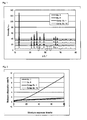
- The invention is described in detail in conjunction with the drawings, in which:
-
Fig. 1 is an example of XRD spectra showing data of positive-electrode active materials of the embodiment and comparative positive-electrode active materials, -
Fig. 2 illustrates an example of moisture absorption data of positive-electrode active materials of the embodiment and comparative positive-electrode active materials, and -
Fig. 3 illustrates an example of cycle characteristics of non-aqueous secondary batteries involving positive-electrode active materials of the embodiment and comparative positive-electrode active materials in the positive-electrodes. - Hereinbelow, positive-electrode active materials for non-aqueous secondary battery and methods for producing the active materials according to the present invention will be described in detail with reference to embodiments and examples.
- First, the positive-electrode active materials for non-aqueous secondary battery, hereinafter, also written simply as "positive-electrode active materials", according to the present invention will be discussed in detail.
- The positive-electrode active material for non-aqueous secondary battery of the invention includes a sodium transition metal composite oxide that is represented by Formula NaxFe1-yMyO2, wherein 0.4 ≤ x ≤ 0.7, 0.25 ≤ y < 1.0, and M is at least one element selected from the group consisting of manganese, cobalt and nickel and has a crystal structure substantially composed of P63/mmc alone.
- Here, the presence of a P63/mmc structure in the crystal structure may be identified based on, for example, a powder X-ray diffractometry (XRD) spectrum. The phrase "substantially composed of P63/mmc alone" means that the crystal structure may include other subphases in addition to the P63/mmc structure as long as the advantageous effects of the invention are achieved. Specifically, the content of the P63/mmc structure is not less than 95%, and preferably not less than 98% of the crystal structure.
- The chemical composition of the sodium transition metal composite oxide that is the main component is represented by the above formula. By limiting x to 0.4 ≤ x ≤ 0.7, the main crystal structure of the sodium transition metal composite oxide is P63/mmc and the breakage of the crystal structure by the desorption and insertion of sodium ions is prevented. It should be noted that the crystal structure starts to shift from the P63/mmc if the value of x is outside the above range. For example, the crystal takes an R-3m structure when x is around 1. A preferred range is 0.5 ≤ x ≤ 0.7. While conventional sodium transition metal composite oxides with a P63/mmc structure inevitably contain subphases having other crystal structures, the sodium transition metal composite oxide obtained by the producing methods of the invention is substantially composed of a P63/mmc structure alone.
- By limiting y to 0.25 ≤ y < 1.0, the obtainable P63/mmc sodium transition metal composite oxide attains good crystallinity. It should be noted that any value of y outside this range causes a decrease in crystallinity and/or the occurrence of subphases. A preferred range is 0.25 ≤ y ≤ 0.75.
- The letter M is at least one element selected from the group consisting of manganese, cobalt and nickel having a similar ion radius to iron. The use of these elements M advantageously makes it easy to obtain the desired crystal structure. When M is manganese, the target material with a stable crystal structure may be obtained easily.
- The positive-electrode active material of the invention sometimes contains a trace amount of oxo acid ions. According to ICP-AES (inductively coupled plasma atomic emission spectrometry), the content of oxo acid ions is preferably not more than 0.3 wt%, more preferably not more than 0.1 wt%, further preferably not more than 0.05 wt%, and particularly preferably below the detection limit or around the detection limit (about 300 ppm). Examples of the oxo acid ions include sulfate ions and nitrate ions.
- Preferably, the crystal structure of the positive-electrode active material of the invention shows a specific characteristic in powder X-ray diffractometry. When, for example, the peak intensity assigned to the (110) plane has a high ratio to the peak intensity assigned to the (016) plane, hereinafter, also written as "(110)/(016)", the crystal structure achieves higher strength and becomes more resistant to breakage by the desorption and insertion of sodium ions, resulting in improved cycle characteristics. The peak intensity ratio is preferably not less than 0.30. A peak intensity ratio higher than 2.00 indicates a possibility of the presence of crystal phases other than the P63/mmc phase. Thus, the peak intensity ratio is preferably not more than 2.00, more preferably 0.35 to 1.00, and particularly preferably 0.40 to 0.80.
- The (110) plane shows a diffraction peak in the range where 28 is 61.2° to 61.7°, and the (016) plane shows a diffraction peak in the range where 28 is 63.3° to 63.8°.
- The integral widths of the (016) plane peak and the (110) plane peak serve as an indicator of how well the sodium transition metal composite oxide has been crystallized. Smaller widths are more preferable. The integral width is preferably not more than 1.00°, and more preferably not more than 0.50° for the (016) plane peak, and is preferably not more than 0.30°, and more preferably not more than 0.25° for the (110) plane peak. A realistic value of the integral width is 0.10° or above for both peaks.
- In the positive-electrode active material, the content of the sodium transition metal composite oxide represented by the above formula is not particularly limited. For example, the content may be 80 mass% or more, and preferably 95 mass% or more. It is more preferable that the positive-electrode active material is substantially composed of the sodium transition metal composite oxide represented by the above formula alone. The term "substantially" means that the positive-electrode active material may include compounds other than the sodium transition metal composite oxide represented by the above formula as long as the advantageous effects of the invention are achieved.
- The positive-electrode active materials for non-aqueous secondary battery of the invention may be preferably produced by any of the following production methods which advantageously allow for efficient production.
- Next, there will be described the methods for producing positive-electrode active materials for non-aqueous secondary battery according to the invention. The inventive methods for producing positive-electrode active materials for non-aqueous electrolyte secondary battery may be performed largely in two embodiments.
- In the method for producing a positive-electrode active material for non-aqueous secondary battery of the invention, the first embodiment is a method for producing a positive-electrode active material for non-aqueous secondary battery including a sodium transition metal composite oxide represented by Formula NaxFe1-yMyO2, wherein 0.4 ≤ x ≤ 0.7, 0.25 ≤ y < 1.0, and M is at least one element selected from the group consisting of manganese, cobalt and nickel, and is characterized by including a precipitate formation step of obtaining a precipitate of a transition metal composite compound from a transition metal ion-containing aqueous solution, a heat treatment step of heat treating the precipitate from the precipitate formation step to obtain a transition metal composite oxide precursor, a mixing step of mixing the precursor from the heat treatment step with at least a sodium compound to obtain a raw material mixture, and a calcination step of calcining the raw material mixture from the mixing step to obtain a calcined product.
- The sodium transition metal composite oxide that is the main component in the target positive-electrode active material is represented by the above formula. Details are as mentioned in the description of the positive-electrode active materials for non-aqueous secondary battery according to the invention.
- In the precipitate formation step, a precipitate of a transition metal composite compound is obtained from a transition metal ion-containing aqueous solution. The precipitate formation step is preferably a step in which a basic compound such as sodium hydroxide is added to the transition metal ion-containing aqueous solution to adjust the pH and to obtain a precipitate of a poorly soluble transition metal composite compound.
- The transition metal ion-containing aqueous solution may be appropriately prepared by, for example, dissolving transition metal compounds such as chlorides, sulfate salts and nitrate salts into an acid or pure water, or by dissolving transition metals into an acid. Any appropriate acids such as hydrochloric acid, nitric acid and sulfuric acid may be selected in accordance with the solutes. In view of factors such as loads to the facility and the environment, availability and easiness in handling, the transition metal ion-containing aqueous solution that is obtained is preferably an aqueous sulfate salt solution. When an aqueous sulfate salt solution is used, the heat treatment step described later has a particular importance.
- The transition metal ion-containing aqueous solution contains at least iron ions, and further contains ions of at least one transition metal selected from the group consisting of manganese, cobalt and nickel (hereinafter, also written as specific transition metal ions). The ratio of the content of iron ions to the content of specific transition metal ions may be selected appropriately in accordance with the chemical composition of the target transition metal composite compound.
- Examples of the poorly soluble transition metal composite compounds include hydroxides, carbonate salts and oxalate salts. From the viewpoint of handling, hydroxides are preferable.
- In the heat treatment step, the transition metal composite compound obtained in the precipitation step is heat treated to form a transition metal composite oxide precursor. This step removes the counter ions (for example, sulfate ions when the transition metal ion-containing aqueous solution is an aqueous sulfate salt solution) from the transition metal composite compound, resulting in a transition metal composite oxide precursor which contains less impurities and has been crystallized to a degree. The counter ions remaining in the precursor cause a decrease in the crystallinity of the final sodium transition metal composite oxide. When, in particular, the counter ions are sulfate ions, the importance of this step further increases because the sulfate ions will remain even in the final sodium transition metal composite oxide to possibly adversely affect moisture absorption properties and various battery characteristics.
- The temperature of the heat treatment requires careful control because the treatment at an excessively low temperature results in insufficient crystallization and insufficient counter ion removal while too high temperatures cause sintering to proceed excessively and undesired phases to occur. To fulfill the purpose, the heat treatment temperature is preferably in the range of 600°C to 1000°C, although the tendencies of heat treatment vary slightly depending on the chemical composition. The heating temperature is more preferably 800°C to 950°C because the unity or uniformity of the crystal structure is markedly increased.
- The heat treatment is performed for at least a certain time period because too short a treatment time does not allow the reaction to complete. The heat treatment time may be extended to any extent without a problem. However, performing the heat treatment for an overly long time only protracts the step and is thus not necessary. In view of these, the heat treatment time is preferably 0.5 hours to 50 hours, and more preferably 3 hours to 24 hours.
- The heat treatment step may be performed in any atmosphere without limitation, but is preferably carried out in an oxidizing atmosphere. Examples of the oxidizing atmospheres include air atmosphere and oxygen-containing atmospheres.
- In the mixing step, the precursor is mixed with at least a sodium compound to give a raw material mixture. The sodium compounds may be any compounds which can be decomposed into oxides at high temperatures, with examples including sodium carbonate, sodium hydroxide, sodium oxide, sodium peroxide, sodium chloride, sodium nitrate and sodium sulfate. In particular, sodium oxide and sodium peroxide are preferable due to their high reactivity in the calcination step, but this characteristic also requires careful attention in the mixing step such as the need of handling the compound in an inert atmosphere such as nitrogen or argon. Sodium carbonate is advantageously easy to handle in the mixing step. The sodium compounds such as sodium nitrate should be handled sufficiently carefully although the counter ions in these compounds are removed more easily in the subsequent calcination step compared to the counter ions contained in the precursor. From these viewpoints, sodium compounds other than strong acid salts are preferable such as sodium carbonate, sodium hydroxide, sodium oxide and sodium peroxide.
- The mixing ratio of the precursor to the sodium compound in the raw material mixture may be selected appropriately in accordance with the chemical composition of the target sodium transition metal composite oxide. The raw material mixture may further contain additives such as sintering auxiliaries (fluxes) in accordance with the purpose.
- The mixing step may involve using any of known mixers such as ball mills, twin-cylinder mixers and stirrers.
- In the calcination step, the raw material mixture from the mixing step is calcined to give a calcined product. Any of known calcination means may be selected appropriately in accordance with the purpose. For example, the raw material mixture may be compacted before the calcination or may be charged into a crucible directly.
- Examples of the calcination furnaces which may be used include batch furnaces, tunnel furnaces and rotary kilns. The calcination temperature needs to be controlled carefully because too low calcination temperatures cause undesired subphases to occur and too high calcination temperatures cause sintering to proceed excessively. Calcination temperatures of 700°C to 1100°C advantageously ensure that a calcined product with a P63/mmc phase may be obtained. The calcination temperature is more preferably 800°C to 1000°C.
- The calcination step may be performed in any atmosphere without limitation, but is preferably carried out in an oxidizing atmosphere. Examples of the oxidizing atmospheres include air atmosphere and oxygen-containing atmospheres.
- The calcined product obtained above may be subjected to treatments such as pulverization, washing and sieving as required, thereby obtaining a positive-electrode active material for non-aqueous secondary battery including the target sodium transition metal composite oxide.
- In the method for producing a positive-electrode active material for non-aqueous secondary battery of the invention, the second embodiment is a method for producing a positive-electrode active material for non-aqueous secondary battery including a sodium transition metal composite oxide represented by Formula NaxFe1-yMyO2 (wherein 0.4 ≤ x ≤ 0.7, 0.25 ≤ y < 1.0, and M is at least one element selected from the group consisting of manganese, cobalt and nickel), and is characterized by including a precipitate formation step of obtaining a precipitate based on (namely, containing as a main component) a transition metal composite compound other than a hydroxide from a transition metal ion-containing aqueous solution, a mixing step of mixing the precipitate from the precipitate formation step with at least a sodium compound to obtain a raw material mixture, and a calcination step of calcining the raw material mixture from the mixing step to obtain a calcined product.
- The chemical composition is similar to that described in the first embodiment.
- In the precipitate formation step, a precipitate based on a transition metal composite compound other than a hydroxide is obtained from a transition metal ion-containing aqueous solution. The precipitate formation step is preferably a step in which a basic compound such as sodium hydroxide is added to the transition metal ion-containing aqueous solution to adjust the pH, and a specific precipitating agent is added to obtain a precipitate of a poorly soluble transition metal composite compound. This precipitate is based on a transition metal composite compound derived from the precipitating agent, and contains no or little hydroxide. Although variable depending on conditions such as the pH value adjusted and the precipitating agent used, the content of hydroxide ions in the precipitate is preferably about 3 mol% or less, and particularly preferably 1 mol% or less relative to 100 mol% of the anions derived from the precipitating agent.
- The transition metal ion-containing aqueous solution may be appropriately prepared by, for example, dissolving transition metal compounds such as chlorides, sulfate salts and nitrate salts into an acid or pure water, or by dissolving transition metals into an acid. Any appropriate acids such as hydrochloric acid, nitric acid and sulfuric acid may be selected in accordance with the solutes. In view of factors such as loads to the facility and the environment, availability and easiness in handling, the transition metal ion-containing aqueous solution that is obtained is preferably an aqueous sulfate salt solution.
- The transition metal ion-containing aqueous solution contains at least iron ions, and further contains at least one type of specific transition metal ions selected from the group consisting of manganese, cobalt and nickel. The ratio of the content of iron ions to the content of specific transition metal ions may be selected appropriately in accordance with the chemical composition of the target transition metal composite compound.
- Examples of the poorly soluble transition metal composite compounds include carbonate salts and oxalate salts. Carbonate salts are preferable from the viewpoint of the relation with the precipitating agent as will be described below and also from the viewpoint of the performance of the positive-electrode active material.
- A precipitate obtained by pH adjustment alone is based on a hydroxide, hereinafter, also written as hydroxide precipitate for convenience. A hydroxide precipitate formed sometimes contains the counter ions present in the transition metal ion-containing aqueous solution, for example, sulfate ions in the case of an aqueous sulfate salt solution. The remaining of the counter ions can cause a decrease in the crystallinity of the final sodium transition metal composite oxide. When, in particular, the counter ions are sulfate ions, the sulfate ions will remain even in the final sodium transition metal composite oxide to possibly adversely affect moisture absorption properties and various battery characteristics. To prevent such problems, a precipitating agent is used in combination with the pH adjustment to form a precipitate that is based on a transition metal composite compound other than a hydroxide. In this manner, the precipitate is prevented from containing an excessively large amount of undesired counter ions.
- Examples of the precipitating agents include carbon dioxide, water-soluble carbonate salts, oxalic acid and water-soluble oxalate salts. From viewpoints such as easiness in handling and costs, carbon dioxide and water-soluble carbonate salts are preferable, and carbon dioxide is particularly preferable.
- Prior to the mixing step described below, the transition metal composite compound from the precipitate formation step may be subjected to a heat treatment to form a transition metal composite oxide. Even in the case where a slight amount of a hydroxide precipitate has been formed in the precipitate formation step, this heat treatment removes sufficiently the counter ions from the precipitate of the transition metal composite compound. Although variable depending on the chemical composition, the heat treatment temperature may be appropriately 600°C to 1000°C. At such temperatures, the counter ions may be removed to a sufficient extent without causing excessive sintering. For details in the heat treatment step, refer to the description of the heat treatment step in the first embodiment.
- In the mixing step, the precipitate, or the transition metal composite oxide from the heat treatment step, is mixed with at least a sodium compound to give a raw material mixture. The sodium compounds may be any compounds which can be decomposed into oxides at high temperatures, with examples including sodium carbonate, sodium hydroxide, sodium oxide, sodium peroxide, sodium chloride, sodium nitrate and sodium sulfate. In particular, sodium oxide and sodium peroxide are preferable due to their high reactivity in the calcination step, but this characteristic also requires careful attention in the mixing step such as the need of handling the compound in an inert atmosphere such as nitrogen or argon. Sodium carbonate is advantageously easy to handle in the mixing step. The sodium compounds such as sodium nitrate should be handled sufficiently carefully although the counter ions in these compounds are removed more easily in the subsequent calcination step compared to the counter ions contained in the precipitate. From these viewpoints, sodium compounds other than strong acid salts are preferable such as sodium carbonate, sodium hydroxide, sodium oxide and sodium peroxide.
- The mixing ratio of the precipitate to the sodium compound in the raw material mixture may be selected appropriately in accordance with the chemical composition of the target sodium transition metal composite oxide. The raw material mixture may further contain additives such as sintering auxiliaries (fluxes) in accordance with the purpose.
- The mixing step may involve using any of known mixers such as ball mills, twin-cylinder mixers and stirrers.
- The calcination step is performed in accordance with the first embodiment.
- Additional steps may be performed in accordance with the first embodiment.
- Next, an example will be described in which non-aqueous secondary batteries are manufactured with the positive-electrode active materials for non-aqueous secondary battery of the invention.
- The positive-electrode active material for non-aqueous secondary battery may be mixed with known components such as a conductive material and a binder to give a positive-electrode mixture, which is then applied to a known positive-electrode collector to form a positive-electrode active material layer. Thus, a positive-electrode for non-aqueous secondary battery may be obtained.
- Examples of the conductive materials include natural graphite, artificial graphite and acetylene black. Examples of the binders include polyvinylidene fluoride, polytetrafluoroethylene and polyamide acrylic resin.
- Examples of the materials of positive-electrode collectors include aluminum, nickel and stainless steel.
- For example, the positive-electrode active material layer may be formed by dispersing the positive-electrode mixture in a solvent, applying the dispersion to the positive-electrode collector, and drying and pressing the wet coating, or may be formed by directly providing the positive-electrode mixture on the positive-electrode collector by pressure forming.
- A non-aqueous secondary battery may be obtained using the positive-electrode for non-aqueous secondary battery obtained above and other known components such as a negative electrode for non-aqueous secondary battery, a non-aqueous electrolytic solution or a solid electrolyte, and a separator.
- The negative electrode for non-aqueous secondary battery may be obtained by applying a known negative electrode active material for non-aqueous secondary battery on a known negative electrode collector to form a negative electrode active material layer.
- Examples of the negative electrode active materials include metallic sodium, sodium alloys and materials capable of doping and dedoping of sodium ions. Exemplary materials capable of doping and dedoping of sodium ions include carbonaceous materials, chalcogen compounds such as oxides and sulfides capable of sodium ion doping and dedoping at lower potential than the positive-electrode, and borate salts. Where necessary, the negative electrode active material may form a negative electrode mixture with a thermoplastic resin as a binder. Examples of the thermoplastic resins include polyvinylidene fluoride, polyethylene and polypropylene.
- Examples of materials for the negative electrode collectors include aluminum, copper, nickel and stainless steel. Aluminum is preferable due to easiness in thin film production and inexpensiveness. In contrast to lithium ion batteries, sodium ion batteries allow use of aluminum as negative electrode collectors. Thus, sodium ion batteries surpass lithium ion batteries in terms of cost and easy handling. For example, the negative electrode active material layer may be formed by directly providing the negative electrode active material or the negative electrode mixture on the negative electrode collector by pressure forming, or may be formed by dispersing the negative electrode active material optionally together with other components in a solvent, applying the dispersion on the negative electrode collector, and drying and pressing the wet coating.
- When the transportation of sodium ions is mediated by a non-aqueous electrolytic solution, the solvent of the electrolytic solution may be an organic solvent. Examples thereof include dimethoxyethane, diethoxyethane, ethylene carbonate, propylene carbonate, dimethyl carbonate, diethyl carbonate, methyl ethyl carbonate, methyl formate, γ-butyrolactone, 2-methyltetrahydrofuran, dimethylsulfoxide and sulfolane.
- Examples of the electrolytes include sodium salts such as sodium perchlorate, sodium tetrafluoroborate, sodium hexafluorophosphate and sodium trifluoromethanesulfonate. The electrolytic solution may be gelled by the addition of an agent such as a gelling agent. Further, the electrolytic solution may be absorbed into an absorbent polymer. The sodium ion concentration in the electrolytic solution may be adjusted appropriately in accordance with the purpose.
- When sodium ions are transported via a solid electrolyte, for example, a polymer compound having a polyethylene oxide backbone, or a polymer compound containing at least one of polyorganosiloxane chains and polyoxyalkylene chains may be used. Further, solid electrolytes including inorganic compounds may be used.
- Examples of the separators include porous films such as of polyethylene and polypropylene.
- The shapes of the non-aqueous secondary batteries are not particularly limited and may be determined in accordance with any known configurations and appropriate modifications of such known shapes.
- Hereinbelow, the present invention will be described in further detail based on Examples without limiting the scope of the invention.
- First, the first embodiment will be described based on some examples.
- Iron (II) sulfate and manganese sulfate were dissolved in pure water such that the ratio of the amounts thereof by mole would be Fe:Mn = 1:1. Thus, a reaction field consisting of an aqueous transition metal sulfate salt solution was prepared. The liquid temperature of the reaction field was adjusted to 50°C. While performing stirring, a prescribed amount of an aqueous sodium hydroxide solution was dropped to the reaction field, thereby obtaining a precipitate of a transition metal composite hydroxide represented by the composition formula (Fe0.5Mn0.5)(OH)2.
- The precipitate was separated from the reaction field and was heat treated in air at 900°C for 12 hours to give a transition metal composite oxide precursor represented by the composition formula (Fe0.5Mn0.5)2O3, hereinafter, also written as "transition metal precursor".
- After the heat treatment, 0.35 mol of sodium carbonate and 1.0 mol of the transition metal precursor were mixed with each other to give a raw material mixture.
- The raw material mixture was calcined in air at 900°C to give a positive-electrode active material represented by the composition formula Na0.7(Fe0.5Mn0.5)O2.
- A positive-electrode active material represented by the composition formula Na0.7(Fe0.5Mn0.5)O2 was obtained in the same manner as in Example 1, except that the heat treatment temperature in the heat treatment step was changed to 650°C.
- A positive-electrode active material represented by the composition formula Na0.7(Fe0.5Mn0.5)O2 was obtained in the same manner as in Example 1, except that the heat treatment step in Example 1 was omitted.
- A positive-electrode active material represented by the composition formula Na0.3(Fe0.5Mn0.5)O2 was obtained in the same manner as in Example 1, except that the mixing step involved 0.15 mol of sodium carbonate.
- A positive-electrode active material represented by the composition formula Na(Fe0.5Mn0.5)O2 was obtained in the same manner as in Example 1, except that the mixing step involved 0.50 mol of sodium carbonate.
- Iron (II) sulfate and manganese sulfate were dissolved in pure water such that the ratio of the amounts thereof by mole would be Fe:Mn = 2:8. Thus, a reaction field consisting of an aqueous transition metal sulfate salt solution was prepared. The liquid temperature of the reaction field was adjusted to 50°C. While performing stirring, a prescribed amount of an aqueous sodium hydroxide solution was dropped to the reaction field, thereby obtaining a precipitate of a transition metal composite hydroxide represented by the composition formula (Fe0.2Mn0.8)(OH)2.
- The precipitate was treated in the same manner as in Example 1 to give a positive-electrode active material represented by the composition formula Na0.7(Fe0.2Mn0.8)O2.
- Iron (II) sulfate and manganese sulfate were dissolved in pure water such that the ratio of the amounts thereof (by mole) would be Fe:Mn = 8:2. Thus, a reaction field consisting of an aqueous transition metal sulfate salt solution was prepared. The liquid temperature of the reaction field was adjusted to 50°C. While performing stirring, a prescribed amount of an aqueous sodium hydroxide solution was dropped to the reaction field, thereby obtaining a precipitate of a transition metal composite hydroxide represented by the composition formula (Fe0.8Mn0.2)(OH)2.
- The precipitate was treated in the same manner as in Example 1 to give a positive-electrode active material represented by the composition formula Na0.7(Fe0.8Mn0.2)O2.
- Manganese sulfate was dissolved in pure water to form a reaction field consisting of an aqueous manganese sulfate solution. The liquid temperature of the reaction field was adjusted to 50°C. While performing stirring, a prescribed amount of an aqueous sodium hydroxide solution was dropped to the reaction field, thereby obtaining a precipitate of manganese hydroxide represented by the composition formula Mn(OH)2.
- The precipitate was treated in the same manner as in Example 1 to give a positive-electrode active material represented by the composition formula Na0.7MnO2.
- Iron (II) sulfate and cobalt sulfate were dissolved in pure water such that the ratio of the amounts thereof by mole would be Fe:Co = 1:1. Thus, a reaction field consisting of an aqueous transition metal sulfate salt solution was prepared. The liquid temperature of the reaction field was adjusted to 50°C. While performing stirring, a prescribed amount of an aqueous sodium hydroxide solution was dropped to the reaction field, thereby obtaining a precipitate of a transition metal composite hydroxide represented by the composition formula (Fe0.5Co0.5)(OH)2.
- The precipitate was treated in the same manner as in Example 1 to give a positive-electrode active material represented by the composition formula Na0.7(Fe0.5Co0.5)O2.
- Iron (II) sulfate and nickel sulfate were dissolved in pure water such that the ratio of the amounts thereof (by mole) would be Fe:Ni = 1:1. Thus, a reaction field consisting of an aqueous transition metal sulfate salt solution was prepared. The liquid temperature of the reaction field was adjusted to 50°C. While performing stirring, a prescribed amount of an aqueous sodium hydroxide solution was dropped to the reaction field, thereby obtaining a precipitate of a transition metal composite hydroxide represented by the composition formula (Fe0.5Ni0.5)(OH)2.
- The precipitate was treated in the same manner as in Example 1 to give a positive-electrode active material represented by the composition formula Na0.7(Fe0.5Ni0.5)O2.
- Next, the second embodiment will be described based on some examples.
- Iron (II) sulfate and manganese sulfate were dissolved in pure water such that the ratio of the amounts thereof by mole would be Fe:Mn = 1:1. Thus, a reaction field consisting of an aqueous transition metal sulfate salt solution was prepared. The liquid temperature of the reaction field was adjusted to 50°C. While performing stirring, a prescribed amount of an aqueous sodium hydroxide solution was dropped and simultaneously a prescribed amount of CO2 gas was blown to the reaction field, thereby obtaining a precipitate of a transition metal composite carbonate salt represented by the composition formula (Fe0.5Mn0.5)CO3. The precipitate was separated from the reaction field and was dried into a powder.
- A raw material mixture was obtained by mixing 0.35 mol of sodium carbonate and 1.0 mol of the precipitate of the transition metal composite carbonate salt.
- The raw material mixture was calcined in air at 900°C to give a positive-electrode active material represented by the composition formula Na0.7(Fe0.5Mn0.5)O2.
- A positive-electrode active material represented by the composition formula Na0.3(Fe0.5Mn0.5)O2 was obtained in the same manner as in Example 6, except that the mixing step involved 0.15 mol of sodium carbonate.
- A positive-electrode active material represented by the composition formula Na(Fe0.5Mn0.5)O2 was obtained in the same manner as in Example 6, except that the mixing step involved 0.50 mol of sodium carbonate.
- Iron (II) sulfate and manganese sulfate were dissolved in pure water such that the ratio of the amounts thereof by mole would be Fe:Mn = 2:8. Thus, a reaction field consisting of an aqueous transition metal sulfate salt solution was prepared. The liquid temperature of the reaction field was adjusted to 50°C. While performing stirring, a prescribed amount of an aqueous sodium hydroxide solution was dropped and simultaneously a prescribed amount of CO2 gas was blown to the reaction field, thereby obtaining a precipitate of a transition metal composite carbonate salt represented by the composition formula (Fe0.2Mn0.8)CO3. The precipitate was separated from the reaction field and was dried into a powder.
- The precipitate was treated in the same manner as in Example 6 to give a positive-electrode active material represented by the composition formula Na0.7(Fe0.2Mn0.8)O2.
- Iron (II) sulfate and manganese sulfate were dissolved in pure water such that the ratio of the amounts thereof by mole would be Fe:Mn = 8:2. Thus, a reaction field consisting of an aqueous transition metal sulfate salt solution was prepared. The liquid temperature of the reaction field was adjusted to 50°C. While performing stirring, a prescribed amount of an aqueous sodium hydroxide solution was dropped and simultaneously a prescribed amount of CO2 gas was blown to the reaction field, thereby obtaining a precipitate of a transition metal composite carbonate salt represented by the composition formula (Fe0.8Mn0.2)CO3. The precipitate was separated from the reaction field and was dried into a powder.
- The precipitate was treated in the same manner as in Example 6 to give a positive-electrode active material represented by the composition formula Na0.7(Fe0.8Mn0.2)O2.
- Manganese sulfate was dissolved in pure water to form a reaction field consisting of an aqueous manganese sulfate solution. The liquid temperature of the reaction field was adjusted to 50°C. While performing stirring, a prescribed amount of an aqueous sodium hydroxide solution was dropped and simultaneously a prescribed amount of CO2 gas was blown to the reaction field, thereby obtaining a precipitate of manganese carbonate represented by the composition formula MnCO3. The precipitate was separated from the reaction field and was dried into a powder.
- The precipitate was treated in the same manner as in Example 6 to give a positive-electrode active material represented by the composition formula Na0.7MnO2.
- Iron (II) sulfate and cobalt sulfate were dissolved in pure water such that the ratio of the amounts thereof by mole would be Fe:Co = 1:1. Thus, a reaction field consisting of an aqueous transition metal sulfate salt solution was prepared. The liquid temperature of the reaction field was adjusted to 50°C. While performing stirring, a prescribed amount of an aqueous sodium hydroxide solution was dropped and simultaneously a prescribed amount of CO2 gas was blown to the reaction field, thereby obtaining a precipitate of a transition metal composite carbonate salt represented by the composition formula (Fe0.5Co0.5)CO3. The precipitate was separated from the reaction field and was dried into a powder.
- The precipitate was treated in the same manner as in Example 6 to give a positive-electrode active material represented by the composition formula Na0.7(Fe0.5Co0.5)O2.
- Iron (II) sulfate and nickel sulfate were dissolved in pure water such that the ratio of the amounts thereof by mole would be Fe:Ni = 1:1. Thus, a reaction field consisting of an aqueous transition metal sulfate salt solution was prepared. The liquid temperature of the reaction field was adjusted to 50°C. While performing stirring, a prescribed amount of an aqueous sodium hydroxide solution was dropped and simultaneously a prescribed amount of CO2 gas was blown to the reaction field, thereby obtaining a precipitate of a transition metal composite carbonate salt represented by the composition formula (Fe0.5Ni0.5)CO3. The precipitate was separated from the reaction field and was dried into a powder.
- The precipitate was treated in the same manner as in Example 6 to give a positive-electrode active material represented by the composition formula Na0.7(Fe0.5Ni0.5)O2.
- A precipitate of a transition metal composite carbonate salt represented by the composition formula (Fe0.5Mn0.5)CO3 was obtained in the same manner as in Example 6. The precipitate was separated from the reaction field and was dried into a powder.
- The transition metal composite carbonate salt was heat treated in air at 900°C for 12 hours to give a transition metal composite oxide represented by the composition formula (Fe0.5Mn0.5)2O3.
- After the heat treatment, 0.35 mol of sodium carbonate and 1.0 mol of the transition metal composite oxide were mixed with each other to give a raw material mixture.
- The raw material mixture was calcined in air at 900°C to give a positive-electrode active material represented by the composition formula Na0.7(Fe0.5Mn0.5)O2.
- Iron (II) sulfate and manganese sulfate were dissolved in pure water such that the ratio of the amounts thereof (by mole) would be Fe:Mn =1:1. Thus, a reaction field consisting of an aqueous transition metal sulfate salt solution was prepared. The liquid temperature of the reaction field was adjusted to 50°C. While performing stirring, prescribed amounts of an aqueous sodium hydroxide solution and an aqueous oxalic acid solution were dropped to the reaction field, thereby obtaining a precipitate of a transition metal composite oxalate salt represented by the composition formula (Fe0.5Mn0.5)(COO)2. The precipitate was separated from the reaction field and was dried into a powder.
- After a drying treatment, 0.35 mol of sodium carbonate and 1.0 mol of the precipitate of the transition metal composite oxalate salt were mixed with each other to give a raw material mixture.
- The raw material mixture was calcined in air at 900°C to give a positive-electrode active material represented by the composition formula Na0.7(Fe0.5Mn0.5)O2.
- Finally, for comparison, a conventional process will be described below.
- Powders of iron (II) oxide, manganese (III) oxide and sodium carbonate were mixed together such that the ratio of the amounts thereof (by mole) would be Na:Fe:Mn = 0.7:0.5:0.5. The resultant raw material mixture was calcined in air at 900°C for 12 hours to give a positive-electrode active material represented by the composition formula Na0.7(Fe0.5Mn0.5)O2.
- The positive-electrode active materials of Examples 1 to 11 and Comparative Examples 1 to 10 were subjected to the following evaluations.
- With a powder X-ray diffractometer, XRD spectra of the positive-electrode active materials were obtained. As the X-ray, CuK α1 radiation (λ = 1.540562 Å) was used. The measurement was performed under conditions of a tube current of 40 mA and a tube voltage of 40 kV.
- The positive-electrode active material weighing 20 g was placed onto a tray and was allowed to stand in a thermostatic chamber in which the dew point was 20°C. After 24 hours and 72 hours, the positive-electrode active material was heated at 200°C. The weight change between before and after the heating was calculated to obtain the moisture absorption rate of the positive-electrode active material.
- Sample batteries were manufactured using the positive-electrode active materials of Examples 1 to 11 and Comparative Examples 1 to 10, and battery characteristics were evaluated.
- In NMP (N-methyl-2-pyrrolidone), 90 parts by weight of the positive-electrode composition, 5.0 parts by weight of acetylene black and 5.0 parts by weight of PVDF (polyvinylidene fluoride) were dispersed to give a positive-electrode slurry. The positive-electrode slurry was applied to an aluminum foil as a collector, dried, and compression formed with a roll press machine. The positive-electrodes were cut to a prescribed size.
- In NMP (N-methyl-2-pyrrolidone), 95 parts by weight of hard carbon and 5.0 parts by weight of PVDF (polyvinylidene fluoride) were dispersed to give a negative electrode slurry. The negative electrode slurry was applied to an aluminum foil as a collector, dried, and compression formed with a roll press machine. The negative electrodes were cut to a prescribed size.
- EC (ethylene carbonate) and DEC (diethyl carbonate) were mixed with each other in a volume ratio of 1:1 to give a mixed solvent. Sodium hexafluorophosphate (NaPF6) was dissolved in the mixed solvent with a concentration of 1 mol/l. Thus, a non-aqueous electrolytic solution was obtained.
- Lead electrodes were attached to the respective collectors of the positive-electrode and the negative electrode, and the electrodes were dried in vacuum at 120°C. Next, a porous polyethylene separator was provided between the positive-electrode and the negative electrode, and the unit was placed into a laminate pack in the form of a bag. The package was dried in vacuum at 60°C to remove water that had been adsorbed onto the components. After the vacuum drying, the non-aqueous electrolytic solution was poured into the laminate pack, and the pack was sealed. In this manner, laminate-type samples of non-aqueous electrolyte secondary batteries were obtained.
- A weak current was applied to the sample battery to perform aging, and thereby the positive-electrode and the negative electrode were allowed to sufficiently conform to the electrolyte. After the aging, the battery was charged by constant current-constant voltage charging with a full charge voltage of 4.4 V and a charging rate of 0.2 C (1 C: a current density at which a fully charged battery is fully discharged in 1 hour) (charging finish conditions: 0.008 C). The capacity obtained was the charge capacity. After the full charging, the battery was discharged at a constant current with a discharging voltage of 1.7 V and a discharging rate of 0.2 C. The capacity obtained was the discharge capacity. The ratio of the discharge capacity to the charge capacity was calculated to determine the charging-discharging efficiency.
- The constant current-constant voltage charging and the constant current discharging described in the charge and discharge characteristics were repeated fifty times, and changes in discharge capacity were studied. The ratio of the discharge capacity in the n-th discharging to the discharge capacity in the first discharging was obtained as the capacity retention Ps (n) after n cycles.
- For Examples 1 to 11 and Comparative Examples 1 to 10, the production conditions, the properties of the positive-electrode active materials, and the battery characteristics for Examples in which M was manganese are described in Tables 1, 2 and 3, respectively, and the production conditions, the properties of the positive-electrode active materials, and the battery characteristics for Examples in which M was cobalt or nickel are described in Tables 4, 5 and 6, respectively. For Examples 1 and 6 and Comparative Examples 1 and 10, the XRD spectra of the positive-electrode active materials are shown in
Fig. 1 , the moisture absorption properties of the positive-electrode active materials are shown inFig. 2 , and the cycle characteristics of the secondary batteries are shown inFig. 3 . InFig. 1 , peaks assigned to the (016) plane are seen in the region where 2θ is about 61.5°, and peaks assigned to the (110) plane are found in the region where 2θ is about 63.7°. The XRD spectra in Examples 2 to 5 and 7 to 11 and in Comparative Examples 5 and 9 were similar to those of Examples 1 and 6.Table 1 x y M Transition metal ions aq. Precipitate Heat treatment temperature /°C Ex. 1 0.7 0.5 Mn Sulfate salt aq. Hydroxide 900 Ex. 2 650 Comp. Ex. 1 - Comp. Ex. 2 0.3 900 Comp. Ex. 3 1 Ex. 3 0.7 0.8 Comp. Ex. 4 0.2 Comp. Ex. 5 1 Ex. 6 0.7 0.5 Mn Sulfate salt aq. Carbonate salt - Comp. Ex. 6 0.3 Comp. Ex. 7 1 Ex. 7 0.7 0.8 Comp. Ex. 8 0.2 Comp. Ex. 9 1 Ex. 10 0.5 Mn 900 Ex. 11 0.5 Oxalate salt - Comp. Ex. 10 0.7 0.5 Mn - - - Table 2 Crystal phase (016) integral width/° (110) Integral width/° (110)/(016) intensity ratio SO4 2- /wt% Moisture absorption rate*/% Ex. 1 P63/mmc 0.31 0.17 0.55 <0.03 1.5 Ex. 2 0.43 0.23 0.53 0.10 3.2 Comp. Ex. 1 1.36 0.30 0.22 0.72 8.0 Comp. Ex. 2 Unidentifiable 0.45 0.22 0.49 <0.03 1.3 Comp. Ex. 3 R-3m 0.36 0.22 0.61 <0.03 1.5 Ex. 3 P63/mmc 0.45 0.21 0.47 <0.03 4.5 Comp. Ex. 4 R-3m·Pna21 0.23 0.19 0.83 <0.03 1.8 Comp. Ex. 5 P63/mmc 0.52 0.22 0.42 <0.03 15.0 Ex. 6 P63/mmc 0.43 0.16 0.37 <0.03 1.3 Comp. Ex. 6 Unidentifiable 0.48 0.22 0.46 <0.03 1.4 Comp. Ex. 7 R-3m 0.42 0.20 0.48 <0.03 1.5 Ex. 7 P63/mmc 0.45 0.20 0.44 <0.03 4.5 Comp. Ex. 8 R-3m·Pna21 0.22 0.19 0.86 <0.03 2.0 Comp. Ex. 9 P63/mmc 0.52 0.21 0.40 <0.03 10.0 Ex. 10 0.32 0.18 0.56 <0.03 1.5 Ex. 11 0.32 0.19 0.59 n.a. 1.8 Gomp. Ex. 10 P63/mmc·R-3m 0.29 0.45 1.55 <0.03 1.0 *After 72 hr
n.a.: not availableTable 3 Charge capacity /mAhg-1 Discharge capacity /mAhg-1 Charging-discharging efficiency/% Ps(50) /% Ex. 1 122 97 79 92 Ex. 2 123 98 79 88 Comp. Ex. 1 124 98 79 76 Comp. Ex. 2 55 42 76 85 Comp. Ex. 3 133 105 79 75 Ex. 3 125 96 77 90 Comp. Ex. 4 106 78 73 72 Comp. Ex. 5 123 94 76 85 Ex. 6 124 97 78 96 Comp. Ex. 6 54 43 80 85 Comp. Ex. 7 134 106 79 73 Ex. 7 125 95 76 88 Comp. Ex. 8 105 78 74 71 Comp. Ex. 9 124 94 76 84 Ex. 10 124 97 78 93 Ex. 11 124 98 79 92 Comp. Ex. 10 123 92 75 92 - From Tables 1 and 2 and
Fig. 1 , the following is reached. - The peaks obtained in Examples 1 and 6 have a higher intensity and a narrower integral width than the peaks of Comparative Example 1, indicating that the P63/mmc structure achieved as high crystallinity as that obtained in Comparative Example 10. This result is probably ascribed to the removal of counter ions (sulfate ions in this case) by the heat treatment. On the other hand, the spectrum of Comparative Example 10 shows peaks indicating the presence of undesired R-3m phase (the three peaks enclosed with a broken line in
Fig. 1 ). This result is probably because the elements were not uniformly mixed together in the mixing of the raw materials. - From Tables 1 and 2 and
Fig. 2 , the following is reached. - Omitting the heat treatment step in the first embodiment allows a large amount of sulfate ions to remain and hence results in high moisture absorption rate as illustrated in Comparative Example 1. The amount of residual sulfate ions is sufficiently decreased and the moisture absorption rate is lowered by performing the heat treatment as demonstrated in Example 1 or by obtaining the positive-electrode active material in accordance with the second embodiment as illustrated in Example 6.
- From Tables 1 to 3 and
Fig. 3 , the following is obtained. - The non-aqueous electrolyte secondary batteries using the positive-electrode active materials of Examples 1 and 6 outperformed the battery based on Comparative Example 1 in terms of cycle characteristics. This result is probably attributed to the difference in crystallinity between Examples 1 and 6 and Comparative Example 1. On the other hand, the non-aqueous electrolyte secondary batteries using the positive-electrode active materials of Examples 1 and 6 achieved higher charging-discharging efficiency than the battery based on Comparative Example 10. This result is probably ascribed to the presence or absence of subphases other than the P63/mmc structure.
- From Tables 1 to 3, the following is reached.
- Values of x falling far outside the range of 0.4 ≤ x ≤ 0.7 cause a failure for the positive-electrode active material to have a P63/mmc single phase structure and result in a decrease in charge-discharge capacity or a deterioration in cycle characteristics as demonstrated in Comparative Examples 2, 3, 6 and 7. Crystallinity is lowered or subphases are caused to occur if the value of y is outside the range of 0.25 ≤ y < 1.0 as illustrated in Comparative Examples 4, 5, 8 and 9.
Table 4 x y M Transition metal ions aq. Precipitate Heat treatment temperature /°C Ex. 4 0.7 0.5 Co Sulfate salt aq. Hydroxide 900 Ex. 5 0.7 0.5 Ni Sulfate salt aq. Hydroxide 900 Ex. 8 0.7 0.5 Co Sulfate salt aq. Carbonate salt - Ex. 9 0.7 0.5 Ni Sulfate s alt aq. Carbonate salt - Table 5 Crystal phase (016) integral width/° (110) Integral width/° (110)/(016) intensity ratio SO4 2- /wt% Moisture absorption rate*/% Ex. 4 P63/mmc 0.35 0.22 0.63 n.a. 1.3 Ex. 5 P63/mmc 0.40 0.25 0.63 n.a. 1.2 Ex. 8 P63/mmc 0.33 0.24 0.73 n.a. 1.5 Ex. 9 P63/mmc 0.35 0.21 0.60 n.a. 1.1 *After 72 hr
n.a.: not availableTable 6 Charge capacity /mAhg-1 Discharge capacity /mAhg-1 Charging-discharging efficiency/% Ps(50) /% Ex. 4 132 98 74 92 Ex. 5 140 101 72 92 Ex. 8 133 99 74 89 Ex. 9 138 103 75 93 - From Tables 4 to 6, the following is obtained.
- Even when M in the formula was replaced manganese with cobalt or nickel, the obtained peaks had a high intensity and a narrow integral width, showing high crystallinity of the P63/mmc structure. Further, the non-aqueous electrolyte secondary batteries obtained in such cases exhibited high charging-discharging efficiency and good cycle characteristics.
- As demonstrated above, the positive-electrode active materials of the invention have good charge and discharge characteristics and good cycle characteristics, and are substantially free from residual counter ions. Thus, the inventive positive-electrode active materials may be suitably used in non-aqueous sodium secondary batteries. Further, the inventive methods for the producing of positive-electrode active materials can produce positive-electrode active materials which are satisfactory both in charge and discharge characteristics and cycle characteristics and in other properties.
Claims (15)
- A positive-electrode active material for non-aqueous secondary battery comprising a sodium transition metal composite oxide represented by Formula:
NaxFe1-yMyO2,
wherein 0.4 ≤ x ≤ 0.7, 0.25 ≤ y < 1.0, and M is at least one element selected from the group consisting of manganese, cobalt and nickel, the sodium transition metal composite oxide having a crystal structure substantially composed of P63/mmc alone. - The positive-electrode active material according to claim 1, wherein the ratio of a peak intensity assigned to the (110) plane to a peak intensity assigned to the (016) plane is 0.30 to 2.00 according to powder X-ray diffractometry.
- The positive-electrode active material according to claim 1 or 2, wherein the integral width of a peak assigned to the (016) plane is 0.10° to 1.00° according to powder X-ray diffractometry.
- The positive-electrode active material according to any one of claims 1 to 3, wherein the integral width of a peak assigned to the (110) plane is 0.10° to 0.30° according to powder X-ray diffractometry.
- The positive-electrode active material according to any one of claims 1 to 4, wherein M is manganese.
- A method for producing a positive-electrode active material for non-aqueous secondary battery including a sodium transition metal composite oxide represented by Formula:
NaxFe1-yMyO2,
wherein 0.4 ≤ x ≤ 0.7, 0.25 ≤ y < 1.0, and M is at least one element selected from the group consisting of manganese, cobalt and nickel, the method comprising:a precipitate formation step of obtaining a precipitate of a transition metal composite compound from a transition metal ion-containing aqueous solution,a heat treatment step of heat treating the precipitate from the precipitate formation step to obtain a transition metal composite oxide precursor,a mixing step of mixing the precursor from the heat treatment step with at least a sodium compound to obtain a raw material mixture, anda calcination step of calcining the raw material mixture from the mixing step to obtain a calcined product. - A method for producing a positive-electrode active material for non-aqueous secondary battery including a sodium transition metal composite oxide represented by Formula:
NaxFe1-yMyO2,
wherein 0.4 ≤ x ≤ 0.7, 0.25 ≤ y < 1.0, and M is at least one element selected from the group consisting of manganese, cobalt and nickel, the method comprising:a precipitate formation step of obtaining a precipitate from a transition metal ion-containing aqueous solution, the precipitate containing a transition metal composite compound other than a hydroxide as a main component,a mixing step of mixing the precipitate from the precipitate formation step with at least a sodium compound to obtain a raw material mixture, anda calcination step of calcining the raw material mixture from the mixing step to obtain a calcined product. - The method according to claim 7, wherein the main component of the precipitate is a transition metal composite carbonate salt.
- The method according to claim 7 or 8, wherein the method further comprises a heat treatment step of heat treating the precipitate from the precipitate formation step to obtain a transition metal composite oxide, and
the mixing step is a step of mixing the transition metal composite oxide with at least a sodium compound to obtain a raw material mixture. - The method according to claim 6 or 9, wherein the heat treatment temperature in the heat treatment step is 600°C to 1000°C.
- The method according to any one of claims 6 to 10, wherein the transition metal ion-containing aqueous solution in the precipitate formation step is an aqueous transition metal sulfate salt solution.
- A composition for a positive-electrode for non-aqueous secondary battery comprising the positive-electrode active material according to any one of claims 1 to 5 and a binder.
- A positive-electrode for non-aqueous secondary battery comprising a positive-electrode collector and a positive-electrode active material layer formed on the positive-electrode collector, wherein the positive-electrode active material layer comprising the positive-electrode active material according to any one of claims 1 to 5.
- A non-aqueous secondary battery comprising a positive-electrode according to claim 13, a negative-electrode and non-aqueous electrolytic solution.
- The use of the positive-electrode active material according to any one of claims 1 to 5 for producing a positive-electrode for non-aqueous secondary battery.
Applications Claiming Priority (3)
| Application Number | Priority Date | Filing Date | Title |
|---|---|---|---|
| JP2013135703 | 2013-06-28 | ||
| JP2013170718 | 2013-08-20 | ||
| JP2014075347A JP6427921B2 (en) | 2013-06-28 | 2014-04-01 | Cathode active material for non-aqueous secondary battery and method for producing the same |
Publications (2)
| Publication Number | Publication Date |
|---|---|
| EP2819222A1 true EP2819222A1 (en) | 2014-12-31 |
| EP2819222B1 EP2819222B1 (en) | 2019-02-27 |
Family
ID=51014183
Family Applications (1)
| Application Number | Title | Priority Date | Filing Date |
|---|---|---|---|
| EP14174752.7A Active EP2819222B1 (en) | 2013-06-28 | 2014-06-27 | Positive-electrode active material for non-aqueous secondary battery and method for producing the same |
Country Status (3)
| Country | Link |
|---|---|
| US (2) | US20150004491A1 (en) |
| EP (1) | EP2819222B1 (en) |
| JP (1) | JP6427921B2 (en) |
Cited By (2)
| Publication number | Priority date | Publication date | Assignee | Title |
|---|---|---|---|---|
| EP3325410A4 (en) * | 2015-07-21 | 2018-05-30 | Sharp Kabushiki Kaisha | Layered oxide materials for batteries |
| US11502296B2 (en) * | 2018-03-26 | 2022-11-15 | Basf Se | Process for making a mixed metal oxide |
Families Citing this family (10)
| Publication number | Priority date | Publication date | Assignee | Title |
|---|---|---|---|---|
| KR102277906B1 (en) * | 2013-11-28 | 2021-07-15 | 삼성전자주식회사 | Cathode active material, secondary battery comprising the same, and preparation method thereof |
| US11387455B2 (en) * | 2017-04-27 | 2022-07-12 | Nippon Electric Glass Co., Ltd. | Positive electrode active material for sodium ion secondary battery |
| CN110817965A (en) * | 2018-08-07 | 2020-02-21 | 山东力盛新能源科技有限公司 | Preparation method of porous microsphere sodium-ion battery positive electrode material |
| US20220212933A1 (en) * | 2019-05-27 | 2022-07-07 | Sagami Chemical Research Institute | Sodium transition metal polyanion and production method thereof |
| CN114229908B (en) * | 2021-11-30 | 2023-07-07 | 广东邦普循环科技有限公司 | Preparation method of P2 type manganese-based sodium ion battery anode material |
| CN114671469B (en) * | 2022-03-31 | 2024-04-02 | 高点(深圳)科技有限公司 | Carbonate grafted oxide type positive electrode material precursor and preparation method and application thereof |
| CN114890482B (en) * | 2022-06-15 | 2023-11-03 | 荆门市格林美新材料有限公司 | Ternary positive electrode precursor and preparation method and application thereof |
| JP7727980B2 (en) * | 2023-11-09 | 2025-08-22 | 合同会社Ttl | Positive electrode active material for sodium secondary battery, positive electrode for sodium secondary battery, and sodium secondary battery |
| CN117613262B (en) * | 2024-01-10 | 2024-07-30 | 武汉理工大学 | Application of iron-based sulfate positive electrode material in sodium ion battery |
| DE102024117628A1 (en) * | 2024-06-21 | 2025-12-24 | Ibu-Tec Advanced Materials Ag | Method and apparatus for the production of a sodium-containing battery material |
Citations (4)
| Publication number | Priority date | Publication date | Assignee | Title |
|---|---|---|---|---|
| JP2005317511A (en) | 2004-03-31 | 2005-11-10 | Junichi Yamaki | Cathode active material for non-aqueous electrolyte secondary battery |
| JP2009135092A (en) | 2007-11-09 | 2009-06-18 | Sumitomo Chemical Co Ltd | Composite metal oxide and sodium secondary battery |
| EP2323204A1 (en) * | 2008-08-27 | 2011-05-18 | Sumitomo Chemical Company, Limited | Electrode active material and method for producing same |
| WO2012060295A1 (en) | 2010-11-05 | 2012-05-10 | 学校法人東京理科大学 | Composite metal oxide, process for producing the composite metal oxide, positive active material for sodium secondary battery, positive electrode for sodium secondary battery, and sodium secondary battery |
Family Cites Families (5)
| Publication number | Priority date | Publication date | Assignee | Title |
|---|---|---|---|---|
| US3931025A (en) * | 1973-09-21 | 1976-01-06 | Bayer Aktiengesellschaft | Magnetic iron oxides with improved orientability and a process for their production |
| DE2556406A1 (en) * | 1975-12-15 | 1977-06-16 | Bayer Ag | PROCESS FOR THE CONTINUOUS PRODUCTION OF IRON OXIDE HYDROXIDE |
| JP5391709B2 (en) * | 2008-02-06 | 2014-01-15 | 住友化学株式会社 | Composite metal oxide and sodium secondary battery |
| CN104854035A (en) * | 2012-12-14 | 2015-08-19 | 松下知识产权经营株式会社 | Composite metal oxide, method for producing composite metal oxide, and sodium secondary battery |
| JP6321973B2 (en) * | 2013-01-23 | 2018-05-09 | 学校法人東京理科大学 | Composite metal oxide, positive electrode active material for sodium secondary battery, positive electrode for sodium secondary battery, and sodium secondary battery |
-
2014
- 2014-04-01 JP JP2014075347A patent/JP6427921B2/en active Active
- 2014-06-27 EP EP14174752.7A patent/EP2819222B1/en active Active
- 2014-06-27 US US14/316,954 patent/US20150004491A1/en not_active Abandoned
-
2018
- 2018-02-13 US US15/895,562 patent/US10522831B2/en active Active
Patent Citations (5)
| Publication number | Priority date | Publication date | Assignee | Title |
|---|---|---|---|---|
| JP2005317511A (en) | 2004-03-31 | 2005-11-10 | Junichi Yamaki | Cathode active material for non-aqueous electrolyte secondary battery |
| JP2009135092A (en) | 2007-11-09 | 2009-06-18 | Sumitomo Chemical Co Ltd | Composite metal oxide and sodium secondary battery |
| EP2323204A1 (en) * | 2008-08-27 | 2011-05-18 | Sumitomo Chemical Company, Limited | Electrode active material and method for producing same |
| WO2012060295A1 (en) | 2010-11-05 | 2012-05-10 | 学校法人東京理科大学 | Composite metal oxide, process for producing the composite metal oxide, positive active material for sodium secondary battery, positive electrode for sodium secondary battery, and sodium secondary battery |
| EP2636649A1 (en) * | 2010-11-05 | 2013-09-11 | Tokyo University Of Science Educational Foundation Administrative Organization | Composite metal oxide, process for producing the composite metal oxide, positive active material for sodium secondary battery, positive electrode for sodium secondary battery, and sodium secondary battery |
Non-Patent Citations (2)
| Title |
|---|
| NAOAKI YABUUCHI ET AL: "P2-type Nax[Fe1/2Mn1/2]O2 made from earth-abundant elements for rechargeable Na batteries", NATURE MATERIALS, vol. 11, no. 6, 29 April 2012 (2012-04-29), pages 512 - 517, XP055135214, ISSN: 1476-1122, DOI: 10.1038/nmat3309 * |
| NATURE MATERIALS, vol. 11, no. 6, 2012, pages 512 - 517 |
Cited By (2)
| Publication number | Priority date | Publication date | Assignee | Title |
|---|---|---|---|---|
| EP3325410A4 (en) * | 2015-07-21 | 2018-05-30 | Sharp Kabushiki Kaisha | Layered oxide materials for batteries |
| US11502296B2 (en) * | 2018-03-26 | 2022-11-15 | Basf Se | Process for making a mixed metal oxide |
Also Published As
| Publication number | Publication date |
|---|---|
| US20180175389A1 (en) | 2018-06-21 |
| JP2015062161A (en) | 2015-04-02 |
| JP6427921B2 (en) | 2018-11-28 |
| EP2819222B1 (en) | 2019-02-27 |
| US10522831B2 (en) | 2019-12-31 |
| US20150004491A1 (en) | 2015-01-01 |
Similar Documents
| Publication | Publication Date | Title |
|---|---|---|
| US10522831B2 (en) | Positive-electrode active material for non-aqueous secondary battery and method for producing the same | |
| Hong et al. | Revealing the correlation between structural evolution and Li+ diffusion kinetics of nickel-rich cathode materials in Li-ion batteries | |
| JP7160075B2 (en) | Positive electrode active material for lithium ion secondary battery and lithium ion secondary battery | |
| JP7180532B2 (en) | Positive electrode active material for lithium ion secondary battery and lithium ion secondary battery | |
| CN107720835B (en) | Precursors for Lithium Transition Metal Oxide Cathode Materials for Rechargeable Batteries | |
| JP7793649B2 (en) | Positive electrode material for lithium-ion batteries and method for producing the same | |
| JP6594132B2 (en) | Battery active material, negative electrode, non-aqueous electrolyte battery, battery pack and vehicle | |
| EP2330079B1 (en) | Method for producing lithium manganate particle powder and nonaqueous electrolyte secondary battery | |
| CN114270567B (en) | Positive electrode active material for lithium-ion secondary batteries and its manufacturing method, and lithium-ion secondary batteries. | |
| EP2544271A1 (en) | Positive electrode active material for lithium-ion battery, positive electrode for lithium-ion battery, and lithium-ion battery | |
| CN105122513B (en) | Active materials for non-aqueous electrolyte battery, nonaqueous electrolyte battery and battery bag | |
| US9537140B2 (en) | Manganese spinel-type lithium transition metal oxide | |
| CN108432001B (en) | Method for producing positive electrode active material, positive electrode, and lithium ion secondary battery | |
| CN111094188B (en) | Metal composite hydroxide and its manufacturing method, positive electrode active material for non-aqueous electrolyte secondary battery and its manufacturing method, and non-aqueous electrolyte secondary battery using the same | |
| KR20120112765A (en) | Method for producing composite oxide, positive electrode material for lithium ion secondary battery and lithium ion secondary battery | |
| CN102177605A (en) | Positive electrode materials for lithium ion batteries having a high specific discharge capacity and processes for the synthesis of these materials | |
| KR20120108031A (en) | Positive electrode active material for lithium ion battery, positive electrode for lithium ion battery, and lithium ion battery | |
| Ruan et al. | Effect of pre-thermal treatment on the lithium storage performance of LiNi0. 8Co0. 15Al0. 05O2 | |
| KR20120042973A (en) | Positive electrode active material for lithium-ion battery, positive electrode for lithium-ion battery, and lithium-ion battery | |
| JP7271848B2 (en) | Method for producing positive electrode active material for lithium ion secondary battery | |
| WO2017046858A1 (en) | Non-aqueous electrolyte cell and cell pack | |
| EP4439720A1 (en) | Positive electrode active material, electrochemical device and electronic device | |
| KR20190052184A (en) | Precursor of positive electrode active material for secondary battery and positive electrode active material prepared by the same | |
| US20170047587A1 (en) | Stabilized electrodes for lithium batteries | |
| KR20120112764A (en) | Process for production of composite oxide, positive electrode active material for lithium ion secondary battery, and lithium ion secondary battery |
Legal Events
| Date | Code | Title | Description |
|---|---|---|---|
| PUAI | Public reference made under article 153(3) epc to a published international application that has entered the european phase |
Free format text: ORIGINAL CODE: 0009012 |
|
| 17P | Request for examination filed |
Effective date: 20140627 |
|
| AK | Designated contracting states |
Kind code of ref document: A1 Designated state(s): AL AT BE BG CH CY CZ DE DK EE ES FI FR GB GR HR HU IE IS IT LI LT LU LV MC MK MT NL NO PL PT RO RS SE SI SK SM TR |
|
| AX | Request for extension of the european patent |
Extension state: BA ME |
|
| R17P | Request for examination filed (corrected) |
Effective date: 20150629 |
|
| RBV | Designated contracting states (corrected) |
Designated state(s): AL AT BE BG CH CY CZ DE DK EE ES FI FR GB GR HR HU IE IS IT LI LT LU LV MC MK MT NL NO PL PT RO RS SE SI SK SM TR |
|
| RIC1 | Information provided on ipc code assigned before grant |
Ipc: H01M 4/52 20100101ALI20180725BHEP Ipc: H01M 4/485 20100101AFI20180725BHEP Ipc: C01G 53/00 20060101ALI20180725BHEP Ipc: H01M 4/505 20100101ALI20180725BHEP Ipc: H01M 10/054 20100101ALI20180725BHEP Ipc: H01M 4/525 20100101ALI20180725BHEP Ipc: C01G 45/00 20060101ALI20180725BHEP Ipc: C01G 51/00 20060101ALI20180725BHEP Ipc: C01G 45/12 20060101ALI20180725BHEP Ipc: C01G 49/00 20060101ALI20180725BHEP |
|
| GRAP | Despatch of communication of intention to grant a patent |
Free format text: ORIGINAL CODE: EPIDOSNIGR1 |
|
| STAA | Information on the status of an ep patent application or granted ep patent |
Free format text: STATUS: GRANT OF PATENT IS INTENDED |
|
| INTG | Intention to grant announced |
Effective date: 20180913 |
|
| GRAS | Grant fee paid |
Free format text: ORIGINAL CODE: EPIDOSNIGR3 |
|
| GRAA | (expected) grant |
Free format text: ORIGINAL CODE: 0009210 |
|
| STAA | Information on the status of an ep patent application or granted ep patent |
Free format text: STATUS: THE PATENT HAS BEEN GRANTED |
|
| AK | Designated contracting states |
Kind code of ref document: B1 Designated state(s): AL AT BE BG CH CY CZ DE DK EE ES FI FR GB GR HR HU IE IS IT LI LT LU LV MC MK MT NL NO PL PT RO RS SE SI SK SM TR |
|
| REG | Reference to a national code |
Ref country code: GB Ref legal event code: FG4D |
|
| REG | Reference to a national code |
Ref country code: CH Ref legal event code: EP |
|
| REG | Reference to a national code |
Ref country code: AT Ref legal event code: REF Ref document number: 1102641 Country of ref document: AT Kind code of ref document: T Effective date: 20190315 |
|
| REG | Reference to a national code |
Ref country code: IE Ref legal event code: FG4D |
|
| REG | Reference to a national code |
Ref country code: DE Ref legal event code: R096 Ref document number: 602014041677 Country of ref document: DE |
|
| REG | Reference to a national code |
Ref country code: NL Ref legal event code: FP |
|
| REG | Reference to a national code |
Ref country code: LT Ref legal event code: MG4D |
|
| PG25 | Lapsed in a contracting state [announced via postgrant information from national office to epo] |
Ref country code: PT Free format text: LAPSE BECAUSE OF FAILURE TO SUBMIT A TRANSLATION OF THE DESCRIPTION OR TO PAY THE FEE WITHIN THE PRESCRIBED TIME-LIMIT Effective date: 20190627 Ref country code: NO Free format text: LAPSE BECAUSE OF FAILURE TO SUBMIT A TRANSLATION OF THE DESCRIPTION OR TO PAY THE FEE WITHIN THE PRESCRIBED TIME-LIMIT Effective date: 20190527 Ref country code: FI Free format text: LAPSE BECAUSE OF FAILURE TO SUBMIT A TRANSLATION OF THE DESCRIPTION OR TO PAY THE FEE WITHIN THE PRESCRIBED TIME-LIMIT Effective date: 20190227 Ref country code: SE Free format text: LAPSE BECAUSE OF FAILURE TO SUBMIT A TRANSLATION OF THE DESCRIPTION OR TO PAY THE FEE WITHIN THE PRESCRIBED TIME-LIMIT Effective date: 20190227 Ref country code: LT Free format text: LAPSE BECAUSE OF FAILURE TO SUBMIT A TRANSLATION OF THE DESCRIPTION OR TO PAY THE FEE WITHIN THE PRESCRIBED TIME-LIMIT Effective date: 20190227 |
|
| PG25 | Lapsed in a contracting state [announced via postgrant information from national office to epo] |
Ref country code: HR Free format text: LAPSE BECAUSE OF FAILURE TO SUBMIT A TRANSLATION OF THE DESCRIPTION OR TO PAY THE FEE WITHIN THE PRESCRIBED TIME-LIMIT Effective date: 20190227 Ref country code: GR Free format text: LAPSE BECAUSE OF FAILURE TO SUBMIT A TRANSLATION OF THE DESCRIPTION OR TO PAY THE FEE WITHIN THE PRESCRIBED TIME-LIMIT Effective date: 20190528 Ref country code: LV Free format text: LAPSE BECAUSE OF FAILURE TO SUBMIT A TRANSLATION OF THE DESCRIPTION OR TO PAY THE FEE WITHIN THE PRESCRIBED TIME-LIMIT Effective date: 20190227 Ref country code: IS Free format text: LAPSE BECAUSE OF FAILURE TO SUBMIT A TRANSLATION OF THE DESCRIPTION OR TO PAY THE FEE WITHIN THE PRESCRIBED TIME-LIMIT Effective date: 20190627 Ref country code: BG Free format text: LAPSE BECAUSE OF FAILURE TO SUBMIT A TRANSLATION OF THE DESCRIPTION OR TO PAY THE FEE WITHIN THE PRESCRIBED TIME-LIMIT Effective date: 20190527 Ref country code: RS Free format text: LAPSE BECAUSE OF FAILURE TO SUBMIT A TRANSLATION OF THE DESCRIPTION OR TO PAY THE FEE WITHIN THE PRESCRIBED TIME-LIMIT Effective date: 20190227 |
|
| REG | Reference to a national code |
Ref country code: AT Ref legal event code: MK05 Ref document number: 1102641 Country of ref document: AT Kind code of ref document: T Effective date: 20190227 |
|
| PG25 | Lapsed in a contracting state [announced via postgrant information from national office to epo] |
Ref country code: EE Free format text: LAPSE BECAUSE OF FAILURE TO SUBMIT A TRANSLATION OF THE DESCRIPTION OR TO PAY THE FEE WITHIN THE PRESCRIBED TIME-LIMIT Effective date: 20190227 Ref country code: DK Free format text: LAPSE BECAUSE OF FAILURE TO SUBMIT A TRANSLATION OF THE DESCRIPTION OR TO PAY THE FEE WITHIN THE PRESCRIBED TIME-LIMIT Effective date: 20190227 Ref country code: RO Free format text: LAPSE BECAUSE OF FAILURE TO SUBMIT A TRANSLATION OF THE DESCRIPTION OR TO PAY THE FEE WITHIN THE PRESCRIBED TIME-LIMIT Effective date: 20190227 Ref country code: CZ Free format text: LAPSE BECAUSE OF FAILURE TO SUBMIT A TRANSLATION OF THE DESCRIPTION OR TO PAY THE FEE WITHIN THE PRESCRIBED TIME-LIMIT Effective date: 20190227 Ref country code: AL Free format text: LAPSE BECAUSE OF FAILURE TO SUBMIT A TRANSLATION OF THE DESCRIPTION OR TO PAY THE FEE WITHIN THE PRESCRIBED TIME-LIMIT Effective date: 20190227 Ref country code: ES Free format text: LAPSE BECAUSE OF FAILURE TO SUBMIT A TRANSLATION OF THE DESCRIPTION OR TO PAY THE FEE WITHIN THE PRESCRIBED TIME-LIMIT Effective date: 20190227 Ref country code: SK Free format text: LAPSE BECAUSE OF FAILURE TO SUBMIT A TRANSLATION OF THE DESCRIPTION OR TO PAY THE FEE WITHIN THE PRESCRIBED TIME-LIMIT Effective date: 20190227 |
|
| REG | Reference to a national code |
Ref country code: DE Ref legal event code: R097 Ref document number: 602014041677 Country of ref document: DE |
|
| PG25 | Lapsed in a contracting state [announced via postgrant information from national office to epo] |
Ref country code: PL Free format text: LAPSE BECAUSE OF FAILURE TO SUBMIT A TRANSLATION OF THE DESCRIPTION OR TO PAY THE FEE WITHIN THE PRESCRIBED TIME-LIMIT Effective date: 20190227 Ref country code: SM Free format text: LAPSE BECAUSE OF FAILURE TO SUBMIT A TRANSLATION OF THE DESCRIPTION OR TO PAY THE FEE WITHIN THE PRESCRIBED TIME-LIMIT Effective date: 20190227 |
|
| PG25 | Lapsed in a contracting state [announced via postgrant information from national office to epo] |
Ref country code: AT Free format text: LAPSE BECAUSE OF FAILURE TO SUBMIT A TRANSLATION OF THE DESCRIPTION OR TO PAY THE FEE WITHIN THE PRESCRIBED TIME-LIMIT Effective date: 20190227 |
|
| PLBE | No opposition filed within time limit |
Free format text: ORIGINAL CODE: 0009261 |
|
| STAA | Information on the status of an ep patent application or granted ep patent |
Free format text: STATUS: NO OPPOSITION FILED WITHIN TIME LIMIT |
|
| PG25 | Lapsed in a contracting state [announced via postgrant information from national office to epo] |
Ref country code: MC Free format text: LAPSE BECAUSE OF FAILURE TO SUBMIT A TRANSLATION OF THE DESCRIPTION OR TO PAY THE FEE WITHIN THE PRESCRIBED TIME-LIMIT Effective date: 20190227 |
|
| REG | Reference to a national code |
Ref country code: CH Ref legal event code: PL |
|
| 26N | No opposition filed |
Effective date: 20191128 |
|
| PG25 | Lapsed in a contracting state [announced via postgrant information from national office to epo] |
Ref country code: SI Free format text: LAPSE BECAUSE OF FAILURE TO SUBMIT A TRANSLATION OF THE DESCRIPTION OR TO PAY THE FEE WITHIN THE PRESCRIBED TIME-LIMIT Effective date: 20190227 |
|
| PG25 | Lapsed in a contracting state [announced via postgrant information from national office to epo] |
Ref country code: TR Free format text: LAPSE BECAUSE OF FAILURE TO SUBMIT A TRANSLATION OF THE DESCRIPTION OR TO PAY THE FEE WITHIN THE PRESCRIBED TIME-LIMIT Effective date: 20190227 |
|
| PG25 | Lapsed in a contracting state [announced via postgrant information from national office to epo] |
Ref country code: IE Free format text: LAPSE BECAUSE OF NON-PAYMENT OF DUE FEES Effective date: 20190627 |
|
| PG25 | Lapsed in a contracting state [announced via postgrant information from national office to epo] |
Ref country code: LI Free format text: LAPSE BECAUSE OF NON-PAYMENT OF DUE FEES Effective date: 20190630 Ref country code: CH Free format text: LAPSE BECAUSE OF NON-PAYMENT OF DUE FEES Effective date: 20190630 Ref country code: LU Free format text: LAPSE BECAUSE OF NON-PAYMENT OF DUE FEES Effective date: 20190627 |
|
| PG25 | Lapsed in a contracting state [announced via postgrant information from national office to epo] |
Ref country code: CY Free format text: LAPSE BECAUSE OF FAILURE TO SUBMIT A TRANSLATION OF THE DESCRIPTION OR TO PAY THE FEE WITHIN THE PRESCRIBED TIME-LIMIT Effective date: 20190227 |
|
| PG25 | Lapsed in a contracting state [announced via postgrant information from national office to epo] |
Ref country code: MT Free format text: LAPSE BECAUSE OF FAILURE TO SUBMIT A TRANSLATION OF THE DESCRIPTION OR TO PAY THE FEE WITHIN THE PRESCRIBED TIME-LIMIT Effective date: 20190227 Ref country code: HU Free format text: LAPSE BECAUSE OF FAILURE TO SUBMIT A TRANSLATION OF THE DESCRIPTION OR TO PAY THE FEE WITHIN THE PRESCRIBED TIME-LIMIT; INVALID AB INITIO Effective date: 20140627 |
|
| PG25 | Lapsed in a contracting state [announced via postgrant information from national office to epo] |
Ref country code: MK Free format text: LAPSE BECAUSE OF FAILURE TO SUBMIT A TRANSLATION OF THE DESCRIPTION OR TO PAY THE FEE WITHIN THE PRESCRIBED TIME-LIMIT Effective date: 20190227 |
|
| P01 | Opt-out of the competence of the unified patent court (upc) registered |
Effective date: 20230522 |
|
| PGFP | Annual fee paid to national office [announced via postgrant information from national office to epo] |
Ref country code: NL Payment date: 20250516 Year of fee payment: 12 |
|
| PGFP | Annual fee paid to national office [announced via postgrant information from national office to epo] |
Ref country code: DE Payment date: 20250429 Year of fee payment: 12 |
|
| PGFP | Annual fee paid to national office [announced via postgrant information from national office to epo] |
Ref country code: GB Payment date: 20250508 Year of fee payment: 12 |
|
| PGFP | Annual fee paid to national office [announced via postgrant information from national office to epo] |
Ref country code: IT Payment date: 20250522 Year of fee payment: 12 Ref country code: BE Payment date: 20250516 Year of fee payment: 12 |
|
| PGFP | Annual fee paid to national office [announced via postgrant information from national office to epo] |
Ref country code: FR Payment date: 20250508 Year of fee payment: 12 |