EP2819206A1 - Electrical accumulator - Google Patents
Electrical accumulator Download PDFInfo
- Publication number
- EP2819206A1 EP2819206A1 EP20130174030 EP13174030A EP2819206A1 EP 2819206 A1 EP2819206 A1 EP 2819206A1 EP 20130174030 EP20130174030 EP 20130174030 EP 13174030 A EP13174030 A EP 13174030A EP 2819206 A1 EP2819206 A1 EP 2819206A1
- Authority
- EP
- European Patent Office
- Prior art keywords
- box
- shaped body
- cover
- rubber
- lower shell
- Prior art date
- Legal status (The legal status is an assumption and is not a legal conclusion. Google has not performed a legal analysis and makes no representation as to the accuracy of the status listed.)
- Granted
Links
- 229920001971 elastomer Polymers 0.000 claims abstract description 43
- 230000005611 electricity Effects 0.000 claims abstract description 6
- 238000000034 method Methods 0.000 claims description 9
- 239000007788 liquid Substances 0.000 claims description 8
- 230000002829 reductive effect Effects 0.000 claims description 6
- 239000011159 matrix material Substances 0.000 claims description 4
- 229920002635 polyurethane Polymers 0.000 claims description 4
- 239000004814 polyurethane Substances 0.000 claims description 4
- 238000001816 cooling Methods 0.000 claims description 3
- 239000012948 isocyanate Substances 0.000 claims description 3
- 150000002513 isocyanates Chemical class 0.000 claims description 3
- 229920005862 polyol Polymers 0.000 claims description 3
- 150000003077 polyols Chemical class 0.000 claims description 3
- 238000002347 injection Methods 0.000 description 7
- 239000007924 injection Substances 0.000 description 7
- 239000000203 mixture Substances 0.000 description 5
- 239000000463 material Substances 0.000 description 4
- 239000004033 plastic Substances 0.000 description 4
- 229920003023 plastic Polymers 0.000 description 4
- 239000002253 acid Substances 0.000 description 3
- 230000002411 adverse Effects 0.000 description 3
- 239000003518 caustics Substances 0.000 description 3
- 238000004891 communication Methods 0.000 description 2
- 238000004146 energy storage Methods 0.000 description 2
- 238000001746 injection moulding Methods 0.000 description 2
- 238000004378 air conditioning Methods 0.000 description 1
- 239000013536 elastomeric material Substances 0.000 description 1
- 239000012530 fluid Substances 0.000 description 1
- 238000009434 installation Methods 0.000 description 1
- 230000000670 limiting effect Effects 0.000 description 1
- 239000007791 liquid phase Substances 0.000 description 1
- 239000002184 metal Substances 0.000 description 1
- 238000000465 moulding Methods 0.000 description 1
- 230000036961 partial effect Effects 0.000 description 1
- 229920003225 polyurethane elastomer Polymers 0.000 description 1
- 230000001681 protective effect Effects 0.000 description 1
- 230000002787 reinforcement Effects 0.000 description 1
- 230000003014 reinforcing effect Effects 0.000 description 1
- 239000007779 soft material Substances 0.000 description 1
- 239000002904 solvent Substances 0.000 description 1
Images


Classifications
-
- H—ELECTRICITY
- H01—ELECTRIC ELEMENTS
- H01M—PROCESSES OR MEANS, e.g. BATTERIES, FOR THE DIRECT CONVERSION OF CHEMICAL ENERGY INTO ELECTRICAL ENERGY
- H01M10/00—Secondary cells; Manufacture thereof
- H01M10/06—Lead-acid accumulators
-
- H—ELECTRICITY
- H01—ELECTRIC ELEMENTS
- H01M—PROCESSES OR MEANS, e.g. BATTERIES, FOR THE DIRECT CONVERSION OF CHEMICAL ENERGY INTO ELECTRICAL ENERGY
- H01M50/00—Constructional details or processes of manufacture of the non-active parts of electrochemical cells other than fuel cells, e.g. hybrid cells
- H01M50/20—Mountings; Secondary casings or frames; Racks, modules or packs; Suspension devices; Shock absorbers; Transport or carrying devices; Holders
- H01M50/204—Racks, modules or packs for multiple batteries or multiple cells
- H01M50/207—Racks, modules or packs for multiple batteries or multiple cells characterised by their shape
- H01M50/209—Racks, modules or packs for multiple batteries or multiple cells characterised by their shape adapted for prismatic or rectangular cells
-
- H—ELECTRICITY
- H01—ELECTRIC ELEMENTS
- H01M—PROCESSES OR MEANS, e.g. BATTERIES, FOR THE DIRECT CONVERSION OF CHEMICAL ENERGY INTO ELECTRICAL ENERGY
- H01M10/00—Secondary cells; Manufacture thereof
- H01M10/60—Heating or cooling; Temperature control
- H01M10/61—Types of temperature control
- H01M10/613—Cooling or keeping cold
-
- H—ELECTRICITY
- H01—ELECTRIC ELEMENTS
- H01M—PROCESSES OR MEANS, e.g. BATTERIES, FOR THE DIRECT CONVERSION OF CHEMICAL ENERGY INTO ELECTRICAL ENERGY
- H01M10/00—Secondary cells; Manufacture thereof
- H01M10/60—Heating or cooling; Temperature control
- H01M10/62—Heating or cooling; Temperature control specially adapted for specific applications
- H01M10/625—Vehicles
-
- H—ELECTRICITY
- H01—ELECTRIC ELEMENTS
- H01M—PROCESSES OR MEANS, e.g. BATTERIES, FOR THE DIRECT CONVERSION OF CHEMICAL ENERGY INTO ELECTRICAL ENERGY
- H01M10/00—Secondary cells; Manufacture thereof
- H01M10/60—Heating or cooling; Temperature control
- H01M10/64—Heating or cooling; Temperature control characterised by the shape of the cells
- H01M10/647—Prismatic or flat cells, e.g. pouch cells
-
- H—ELECTRICITY
- H01—ELECTRIC ELEMENTS
- H01M—PROCESSES OR MEANS, e.g. BATTERIES, FOR THE DIRECT CONVERSION OF CHEMICAL ENERGY INTO ELECTRICAL ENERGY
- H01M10/00—Secondary cells; Manufacture thereof
- H01M10/60—Heating or cooling; Temperature control
- H01M10/65—Means for temperature control structurally associated with the cells
- H01M10/655—Solid structures for heat exchange or heat conduction
- H01M10/6556—Solid parts with flow channel passages or pipes for heat exchange
- H01M10/6557—Solid parts with flow channel passages or pipes for heat exchange arranged between the cells
-
- H—ELECTRICITY
- H01—ELECTRIC ELEMENTS
- H01M—PROCESSES OR MEANS, e.g. BATTERIES, FOR THE DIRECT CONVERSION OF CHEMICAL ENERGY INTO ELECTRICAL ENERGY
- H01M10/00—Secondary cells; Manufacture thereof
- H01M10/60—Heating or cooling; Temperature control
- H01M10/65—Means for temperature control structurally associated with the cells
- H01M10/656—Means for temperature control structurally associated with the cells characterised by the type of heat-exchange fluid
- H01M10/6561—Gases
- H01M10/6562—Gases with free flow by convection only
-
- H—ELECTRICITY
- H01—ELECTRIC ELEMENTS
- H01M—PROCESSES OR MEANS, e.g. BATTERIES, FOR THE DIRECT CONVERSION OF CHEMICAL ENERGY INTO ELECTRICAL ENERGY
- H01M50/00—Constructional details or processes of manufacture of the non-active parts of electrochemical cells other than fuel cells, e.g. hybrid cells
- H01M50/20—Mountings; Secondary casings or frames; Racks, modules or packs; Suspension devices; Shock absorbers; Transport or carrying devices; Holders
- H01M50/256—Carrying devices, e.g. belts
-
- H—ELECTRICITY
- H01—ELECTRIC ELEMENTS
- H01M—PROCESSES OR MEANS, e.g. BATTERIES, FOR THE DIRECT CONVERSION OF CHEMICAL ENERGY INTO ELECTRICAL ENERGY
- H01M50/00—Constructional details or processes of manufacture of the non-active parts of electrochemical cells other than fuel cells, e.g. hybrid cells
- H01M50/20—Mountings; Secondary casings or frames; Racks, modules or packs; Suspension devices; Shock absorbers; Transport or carrying devices; Holders
- H01M50/271—Lids or covers for the racks or secondary casings
- H01M50/273—Lids or covers for the racks or secondary casings characterised by the material
- H01M50/278—Organic material
-
- B—PERFORMING OPERATIONS; TRANSPORTING
- B29—WORKING OF PLASTICS; WORKING OF SUBSTANCES IN A PLASTIC STATE IN GENERAL
- B29C—SHAPING OR JOINING OF PLASTICS; SHAPING OF MATERIAL IN A PLASTIC STATE, NOT OTHERWISE PROVIDED FOR; AFTER-TREATMENT OF THE SHAPED PRODUCTS, e.g. REPAIRING
- B29C45/00—Injection moulding, i.e. forcing the required volume of moulding material through a nozzle into a closed mould; Apparatus therefor
- B29C45/14—Injection moulding, i.e. forcing the required volume of moulding material through a nozzle into a closed mould; Apparatus therefor incorporating preformed parts or layers, e.g. injection moulding around inserts or for coating articles
- B29C45/14639—Injection moulding, i.e. forcing the required volume of moulding material through a nozzle into a closed mould; Apparatus therefor incorporating preformed parts or layers, e.g. injection moulding around inserts or for coating articles for obtaining an insulating effect, e.g. for electrical components
-
- B—PERFORMING OPERATIONS; TRANSPORTING
- B29—WORKING OF PLASTICS; WORKING OF SUBSTANCES IN A PLASTIC STATE IN GENERAL
- B29K—INDEXING SCHEME ASSOCIATED WITH SUBCLASSES B29B, B29C OR B29D, RELATING TO MOULDING MATERIALS OR TO MATERIALS FOR MOULDS, REINFORCEMENTS, FILLERS OR PREFORMED PARTS, e.g. INSERTS
- B29K2021/00—Use of unspecified rubbers as moulding material
-
- H—ELECTRICITY
- H01—ELECTRIC ELEMENTS
- H01M—PROCESSES OR MEANS, e.g. BATTERIES, FOR THE DIRECT CONVERSION OF CHEMICAL ENERGY INTO ELECTRICAL ENERGY
- H01M10/00—Secondary cells; Manufacture thereof
- H01M10/42—Methods or arrangements for servicing or maintenance of secondary cells or secondary half-cells
- H01M10/425—Structural combination with electronic components, e.g. electronic circuits integrated to the outside of the casing
- H01M10/4257—Smart batteries, e.g. electronic circuits inside the housing of the cells or batteries
-
- H—ELECTRICITY
- H01—ELECTRIC ELEMENTS
- H01M—PROCESSES OR MEANS, e.g. BATTERIES, FOR THE DIRECT CONVERSION OF CHEMICAL ENERGY INTO ELECTRICAL ENERGY
- H01M2220/00—Batteries for particular applications
- H01M2220/20—Batteries in motive systems, e.g. vehicle, ship, plane
-
- H—ELECTRICITY
- H01—ELECTRIC ELEMENTS
- H01M—PROCESSES OR MEANS, e.g. BATTERIES, FOR THE DIRECT CONVERSION OF CHEMICAL ENERGY INTO ELECTRICAL ENERGY
- H01M50/00—Constructional details or processes of manufacture of the non-active parts of electrochemical cells other than fuel cells, e.g. hybrid cells
- H01M50/50—Current conducting connections for cells or batteries
- H01M50/543—Terminals
- H01M50/552—Terminals characterised by their shape
- H01M50/553—Terminals adapted for prismatic, pouch or rectangular cells
-
- Y—GENERAL TAGGING OF NEW TECHNOLOGICAL DEVELOPMENTS; GENERAL TAGGING OF CROSS-SECTIONAL TECHNOLOGIES SPANNING OVER SEVERAL SECTIONS OF THE IPC; TECHNICAL SUBJECTS COVERED BY FORMER USPC CROSS-REFERENCE ART COLLECTIONS [XRACs] AND DIGESTS
- Y02—TECHNOLOGIES OR APPLICATIONS FOR MITIGATION OR ADAPTATION AGAINST CLIMATE CHANGE
- Y02E—REDUCTION OF GREENHOUSE GAS [GHG] EMISSIONS, RELATED TO ENERGY GENERATION, TRANSMISSION OR DISTRIBUTION
- Y02E60/00—Enabling technologies; Technologies with a potential or indirect contribution to GHG emissions mitigation
- Y02E60/10—Energy storage using batteries
Definitions
- This invention relates to an electrical accumulator, commonly known as "battery”, used in particular for vehicles such as camper vans, caravans or the like.
- the electrical accumulator according to this invention is of the type which can be used for supplying electricity to auxiliary systems, for example, cab lights, air conditioning system, hot plates etc.
- the energy storage unit for example a lead-acid unit
- the rigid plastic shell comprises a plurality of panels or elements assembled together to cover the box-shaped body.
- the aim of this invention is to provide an electrical accumulator that overcomes the above mentioned drawbacks of the prior art.
- the aim of this invention is to provide an electrical accumulator which has marked resistance to vibrations and impacts.
- Another aim of this invention is to provide an electrical accumulator which has a high flexibility of use, in particular which can be installed without the need to provide specific attachment flanges or the like.
- Yet another aim of this invention is to provide an electrical accumulator which has excellent resistance to adverse weather conditions or corrosive agents.
- This invention also relates to a method for making the electrical accumulator.
- the electrical accumulator comprises an outer cover body designed to protect and inner box-shaped body (forming an energy storage unit).
- the outer cover body is made (entirely, or substantially entirely) of an elastically deformable material, preferably rubber.
- the outer cover made of rubber forms a matrix encapsulating at least a portion of the box-shaped body.
- the invention relates to an electrical accumulator for camper vans (or caravans or other similar vehicles) having a box-shaped body (for protecting the actual batteries) embedded in a elastomeric matrix (that is, a rubber matrix).
- the outer cover is made by injection moulding; in particular, the outer cover is made by injection moulding by injecting rubber (or another elastomeric material) into a mould in a liquid form, for then being solidified about at least a portion of the outer surface of the box-shaped body.
- the rubber is a polyurethane mix; preferably, the rubber comprises a mix of isocyanate and polyol.
- the rubber is obtained by mixing the materials in the liquid phase, and this is followed by solidifying the liquid mix, to form a soft material.
- the rubber is soft; preferably, it is a polyurethane rubber.
- reinforcement elements such as, for example, filaments or plates, made from material having a mechanical strength greater than the rubber, for example made of metal.
- the cover in a relative undeformed configuration, is shaped to match and adheres to at least a part of the outer profile of the box-shaped body.
- the box-shaped body is formed by a plurality of batteries placed side by side to form a battery pack and the cover covers entirely at least the outer corners of the battery pack.
- the batteries are shaped in such a way as to form, between them, a plurality of longitudinal conduits which extend vertically for the entire height of the battery pack for forming respective paths for the passage of cooling air.
- the box-shaped body is formed by a single battery, for example of the lead-acid type, and the cover covers entirely at least the outer corners of the battery.
- the cover preferably covers the battery pack already formed by the side by side positioning of the batteries.
- the cover covers each battery of the battery pack independently from one another.
- the box-shaped body has a lower supporting surface, a lateral surface and an upper surface, and the cover comprises:
- the lower shell comprises a single block made from rubber; if necessary, provided with the above-mentioned reinforcing elements embedded in the rubber.
- the cover also comprises a single block made from rubber.
- the cover has at least one stretch with a linear extension having reduced thickness, preferably between 5 mm and 25 mm, positioned between two mutually adjacent portions of the cover.
- the stretch with reduced thickness preferably comprising a rectilinear groove made on a surface of the cover facing towards the inside of the lower shell and therefore towards the battery pack, forms a planned line of weakness designed to constitute a line for hinging the first portion of the cover (forming a reclosable door) with respect to the second portion of the cover.
- the lower shell has a bottom wall having a bottom through opening facing the above-mentioned conduits enclosed between the batteries.
- the bottom wall of the lower shell preferably has at least one horizontal groove extending between the bottom opening and a lateral surface of the lower shell.
- the lower shell also has, on lateral surfaces facing each other, a pair of lateral handles made in one piece with the lateral surfaces, therefore also made of rubber, using the same injection process as the cover.
- the method for making the accumulator according to this invention comprises a step for inserting the box-shaped (irrespective of the specific embodiment of the box-shaped body) in a mould and subsequent step of injecting rubber in the liquid state in the mould and in contact with the box-shaped body in such a way that the rubber coats at least partly the box-shaped body.
- the step of injecting rubber is performed in such a way that the rubber coats at least a part of a bottom surface and an entire lateral surface of the box-shaped body, leaving at least party free an upper surface of the box-shaped body, so as to form the lower shell of the cover.
- the rubber does not cover entirely the bottom surface of the box-shaped body but leaves a part free, preferably a predominant part, for forming the above-mentioned bottom opening.
- the cover is made by a further injection step different from the step for injecting the lower shell and it is achieved by preparing an auxiliary mould different from the mould used in the step of injecting the lower shell, also in this case injecting rubber in the liquid state in the auxiliary mould.
- the accumulator 1 as shown in the exploded view of Figure 1 , basically comprises a box-shaped body 2, forming the unit for storing electricity (for example, a lead-acid type unit) and an outer cover 3 applied outside the box-shaped body 2.
- electricity for example, a lead-acid type unit
- the box-shaped body 2 can be of the conventional type, more specifically having a box-shaped structure made from rigid plastic equipped with a suitable electronic control (comprising one or more electronic cards and relative connections, partly visible in Figure 1 and identified with "E") and suitable electrodes and electrical connections for the connection, respectively, to a network to be powered and a control circuit.
- a suitable electronic control comprising one or more electronic cards and relative connections, partly visible in Figure 1 and identified with "E”
- suitable electrodes and electrical connections for the connection, respectively, to a network to be powered and a control circuit.
- the box-shaped body 2 comprises a plurality of batteries “B” (in the specific case, four batteries) positioned side by side to form a battery pack.
- the batteries "B” have the same height and are placed side by side with each other.
- the battery pack 2 (or, more generally, the box-shaped body 2) has overall a substantially prismatic shape having a rectangular base and a lower supporting surface 2a, a lateral surface 2b (comprising four flat panels) and an upper surface 2c.
- the cover 3 covers entirely at least the lateral surface 2b and the upper surface 2c of the battery pack 2.
- the cover 3 does not cover entirely the lower surface 2a of the battery pack 2 but forms a bottom opening 4 the purpose of which is described in detail below.
- the bottom opening 4 has a surface extension corresponding to a main part of the of the lower surface 2a of the battery pack 2.
- the cover 3 comprises a lower shell 3a which covers entirely at least the outer corners of the lower surface 2a and of the lateral surface 2b of the battery pack 2, leaving at least partially free (preferably entirely) the upper surface 2c of the battery pack 2, and an upper cover 3b for closing the lower shell 3a.
- the lower shell 3a forms a container designed to contain the battery pack 2 and inside forms a compartment 5 (open below with the above-mentioned bottom opening 4) preferably having a height such as to contain entirely the battery pack 2.
- the lower shell 3a covers entirely at least the outer corners of the lower surface 2a and of the lateral surface 2b of the box-shaped body 2, leaving at least partially free the upper surface 2c of the box-shaped body 2.
- the lower shell 3a has on the outside, on the relative bottom surface, one of more grooves 6 (three grooves in the embodiment shown) extending between the bottom opening 4 and a lateral surface of the battery pack 2.
- the grooves 6 form respective channels for the passage of air putting in communication the bottom opening 4 with the outside environment when the accumulator 1 is located on a supporting surface.
- the batteries “B” are shaped in such a way as to form, between them, a plurality of conduits 7 extending between the lower surface 2A and the upper surface 2c of the battery pack 2 for allowing a vertical flow of cooling air.
- the conduits 7 are therefore in fluid communication with the bottom opening 4 and, consequently, with the grooves 6.
- the cover 3b is formed by a panel positioned for closing the lower shell 3a.
- the cover 3b therefore has a shape substantially corresponding with the transversal cross section of the lower shell 3a.
- the cover 3b has a door 11 hinged along a hinge line and positioned for closing the terminal strip "M" of the accumulator.
- the terminal strip “M” comprises a pair of terminals (only partially illustrated in the drawings) connected, in a way that is not illustrated, to the poles of the batteries "B".
- the cover 3 is made from an elastically deformable material, preferably rubber.
- the rubber is selected from the group comprising a polyurethane mix, more preferably a polyurethane mix of isocyanate and polyol.
- the cover 3 is shaped to match and adheres to at least a part of the outer profile of the battery pack 2 (in particular, as described above, at least to the entire lateral surface 2b of the battery pack 2 and to the lateral corners of the lower surface 2a of the battery pack).
- the lower shell 3a comprises a single block made from rubber.
- the box-shaped body 2 (which encloses the battery pack) has two brackets fixed to relative lateral surfaces; the brackets have a portion which protrudes outwardly, to form a core for supporting the lateral handles 8 of the lower shell 3a.
- the lateral handles 8 of the lower shell 3a surround (and encapsulate) the brackets protruding laterally.
- the cover 3b also comprises a single block made from rubber.
- the cover 3b has at least one stretch 9 with a linear extension having reduced thickness, preferably between 5 and 30 mm, forming the above-mentioned hinge line.
- the stretch 9 with reduced thickness is positioned between two portions mutually adjacent to the cover 3b, in particular a fixed portion 10 and the door 11 for defining the hinging of the door 11 and the rotation of the door between the open and closed limit positions.
- the cover has two valves (fixed portion 10 and door 11); the valves are made from a single mould, that is, in a single cast and are joined by a thinned portion (the stretch 9).
- this allows the electronic card E to be inserted (inserting it in an opening formed by moving the door 11).
- the two valves of the cover 3b are closed (“sandwiched") and glued (or, in any case, fixed) to each other.
- the shell 3 forms a window, having the purpose of uncovering electrical contacts for the battery or for the electronics (the window is preferably made on one of the two valves of the cover 3b).
- the cover 3b also has one or more (pairs of) openings 12 (in the embodiment shown there are four pairs of openings 12, each associated with a respective battery "B").
- openings 12 are to fix the cover 3b to the lower shell 3a using screws and/or to fix the cover 3b to other elements or units outside the shell 3a and rested on the cover 3b.
- the openings 12 are through openings and form at the base a narrowing, so as to define an abutment on which the heads of the screws screwed to fasten the cover 3b to the shell 3a are operatively abutted.
- the cover 3 can be obtained by a process of injecting liquid rubber into a mould.
- the lower shell 3a and the cover 3b are made in two distinct steps using two different moulds.
- the lower shell 3a is preferably made by injecting directly on the box-shaped body 2, or battery pack.
- the handles 8 are also made as a single piece together with the rest of the lower shell 3a, and they are also therefore made of rubber.
- control electronics are also embedded in the rubber, and in particular in the cover 3b (by the injection process).
- the process for making the accumulator 1 comprises the following steps:
- the injection occurs until fully covering the lateral surface 2b of the box-shaped body 2 and the lateral corners of the lower surface 2a of the box-shaped body 2.
- the bottom opening 4 can be advantageously achieved by a suitable projection of the mould, or an external support, which supports the box-shaped body 2 during the injection.
- the drawings show a mould 100 for making the lower shell 3a of the cover 3.
- the mould 100 comprises a base plate 101, designed to face the upper surface 2c of the box-shaped body 2, as well as a first pair of lateral plates 102 which are opposite to each other and a second pair of lateral plates 103 which are also opposite to each other.
- One of the two pairs of lateral plates 102 forms the above-mentioned handles 8.
- the pair of lateral plates 102 forming the handles 8 is uncoupled from the base plate 101 and can be stably connected to it using threaded elements.
- the lateral plates of the other pair 103 are coupled to the base plate 101, for example by hinging about respective axes.
- the mould 100 also comprises one or more auxiliary plates 104 having respective protrusions 104a designed to enter into contact with the lower surface 2a of the box-shaped body 2.
- the protrusions 104a have an overall size corresponding to the above-mentioned bottom opening 4 in such a way that, after injection, the removal of the auxiliary plates 104 makes the bottom opening 4.
- This invention achieves the preset aims.
- the integral and single-block cover, using rubber, of the lateral surfaces of the box-shaped body allows an efficient screen to be made against adverse weather conditions and/or corrosive substances.
- the use of the rubber also improves in a significant fashion the adherence of the accumulator on any supporting surface, making the positioning more stable and eliminating the need for specific attachment or fitting elements.
Landscapes
- Chemical & Material Sciences (AREA)
- Chemical Kinetics & Catalysis (AREA)
- Electrochemistry (AREA)
- General Chemical & Material Sciences (AREA)
- Engineering & Computer Science (AREA)
- Manufacturing & Machinery (AREA)
- Battery Mounting, Suspending (AREA)
Abstract
Description
- This invention relates to an electrical accumulator, commonly known as "battery", used in particular for vehicles such as camper vans, caravans or the like.
- More specifically, the electrical accumulator according to this invention is of the type which can be used for supplying electricity to auxiliary systems, for example, cab lights, air conditioning system, hot plates etc.
- There are currently prior art electrical accumulators comprising a box-shaped body forming the actual the energy storage unit (for example a lead-acid unit), associated with a corresponding control electronics and covered externally with a shell made from rigid plastic. More specifically, the rigid plastic shell comprises a plurality of panels or elements assembled together to cover the box-shaped body.
- Disadvantageously, the electrical accumulators of the above-mentioned type have a number of drawbacks.
- More specifically, they are very susceptible to damage (in particular to the electronic components) following impacts or vibrations, as the plastic shell is not very suitable for absorbing vibrations and impacts.
- Moreover, they require suitable housings or suitable flanges for attachment during installation on the vehicle so that will remain in the correct position during driving.
- Further, it has been found that these accumulators are subject to attack by adverse weather conditions or corrosive substances such as solvents or the like, as the outer shell is not sufficiently protective and has inevitable slits along the joining lines between the various parts.
- For this reason, the aim of this invention is to provide an electrical accumulator that overcomes the above mentioned drawbacks of the prior art.
- More specifically, the aim of this invention is to provide an electrical accumulator which has marked resistance to vibrations and impacts. Another aim of this invention is to provide an electrical accumulator which has a high flexibility of use, in particular which can be installed without the need to provide specific attachment flanges or the like.
- Yet another aim of this invention is to provide an electrical accumulator which has excellent resistance to adverse weather conditions or corrosive agents.
- The aim is fully achieved by the electrical accumulator according to this invention, as characterised in the appended claims.
- This invention also relates to a method for making the electrical accumulator.
- The electrical accumulator comprises an outer cover body designed to protect and inner box-shaped body (forming an energy storage unit). According to the invention, the outer cover body is made (entirely, or substantially entirely) of an elastically deformable material, preferably rubber.
- The outer cover made of rubber forms a matrix encapsulating at least a portion of the box-shaped body.
- Therefore, the invention relates to an electrical accumulator for camper vans (or caravans or other similar vehicles) having a box-shaped body (for protecting the actual batteries) embedded in a elastomeric matrix (that is, a rubber matrix).
- The outer cover is made by injection moulding; in particular, the outer cover is made by injection moulding by injecting rubber (or another elastomeric material) into a mould in a liquid form, for then being solidified about at least a portion of the outer surface of the box-shaped body. Preferably, the rubber is a polyurethane mix; preferably, the rubber comprises a mix of isocyanate and polyol.
- Preferably, the rubber is obtained by mixing the materials in the liquid phase, and this is followed by solidifying the liquid mix, to form a soft material.
- Preferably, the rubber is soft; preferably, it is a polyurethane rubber.
- More specifically, it is possible to increase the mechanical strength of the rubber by embedding inside it reinforcement elements, such as, for example, filaments or plates, made from material having a mechanical strength greater than the rubber, for example made of metal.
- The cover, in a relative undeformed configuration, is shaped to match and adheres to at least a part of the outer profile of the box-shaped body.
- This is achieved by moulding the cover (preferably by injection) directly around the box-shaped body.
- In a preferred embodiment, the box-shaped body is formed by a plurality of batteries placed side by side to form a battery pack and the cover covers entirely at least the outer corners of the battery pack.
- Preferably, the batteries are shaped in such a way as to form, between them, a plurality of longitudinal conduits which extend vertically for the entire height of the battery pack for forming respective paths for the passage of cooling air.
- In a different embodiment, the box-shaped body is formed by a single battery, for example of the lead-acid type, and the cover covers entirely at least the outer corners of the battery.
- Where the box-shaped body is formed by the battery pack, the cover preferably covers the battery pack already formed by the side by side positioning of the batteries.
- However, in a different embodiment, the cover covers each battery of the battery pack independently from one another. Irrespective of the specific embodiment of the box-shaped body, the box-shaped body has a lower supporting surface, a lateral surface and an upper surface, and the cover comprises:
- a lower shell, forming a container, which covers entirely at least the outer corners of the lower surface and of the lateral surface of the box-shaped body, leaving at least partially free the upper surface of the box-shaped body, and
- an upper cover for closing the lower shell.
- Preferably, the lower shell comprises a single block made from rubber; if necessary, provided with the above-mentioned reinforcing elements embedded in the rubber.
- Preferably, the cover also comprises a single block made from rubber. The cover has at least one stretch with a linear extension having reduced thickness, preferably between 5 mm and 25 mm, positioned between two mutually adjacent portions of the cover. The stretch with reduced thickness, preferably comprising a rectilinear groove made on a surface of the cover facing towards the inside of the lower shell and therefore towards the battery pack, forms a planned line of weakness designed to constitute a line for hinging the first portion of the cover (forming a reclosable door) with respect to the second portion of the cover. Preferably, the lower shell has a bottom wall having a bottom through opening facing the above-mentioned conduits enclosed between the batteries.
- In that embodiment, the bottom wall of the lower shell preferably has at least one horizontal groove extending between the bottom opening and a lateral surface of the lower shell.
- The lower shell also has, on lateral surfaces facing each other, a pair of lateral handles made in one piece with the lateral surfaces, therefore also made of rubber, using the same injection process as the cover.
- The method for making the accumulator according to this invention comprises a step for inserting the box-shaped (irrespective of the specific embodiment of the box-shaped body) in a mould and subsequent step of injecting rubber in the liquid state in the mould and in contact with the box-shaped body in such a way that the rubber coats at least partly the box-shaped body.
- The step of injecting rubber is performed in such a way that the rubber coats at least a part of a bottom surface and an entire lateral surface of the box-shaped body, leaving at least party free an upper surface of the box-shaped body, so as to form the lower shell of the cover.
- Preferably, the rubber does not cover entirely the bottom surface of the box-shaped body but leaves a part free, preferably a predominant part, for forming the above-mentioned bottom opening.
- The cover is made by a further injection step different from the step for injecting the lower shell and it is achieved by preparing an auxiliary mould different from the mould used in the step of injecting the lower shell, also in this case injecting rubber in the liquid state in the auxiliary mould.
- The technical features of the invention according to the above mentioned aim are clearly described in the claims below and its advantages are apparent from the detailed description which follows, with reference to the accompanying drawings, which illustrate a preferred non-limiting example embodiment of the invention and in which:
-
Figure 1 shows an electrical accumulator according to this invention; -
Figure 2 is a view from below of the accumulator ofFigure 1 ; -
Figure 3 shows the accumulator ofFigure 1 in a cross section through the line III-III ofFigure 2 ; -
Figure 4 is an exploded view ofFigure 3 ; -
Figures 5A and 5B show a side view of the accumulator ofFigure 1 in two different configurations of use; -
Figure 6 shows a mould for making a part of the accumulator ofFigure 1 ; With reference to the accompanying drawings, thenumeral 1 denotes in its entirety an electrical accumulator according to this invention. - The
accumulator 1, as shown in the exploded view ofFigure 1 , basically comprises a box-shaped body 2, forming the unit for storing electricity (for example, a lead-acid type unit) and anouter cover 3 applied outside the box-shaped body 2. - The box-
shaped body 2 can be of the conventional type, more specifically having a box-shaped structure made from rigid plastic equipped with a suitable electronic control (comprising one or more electronic cards and relative connections, partly visible inFigure 1 and identified with "E") and suitable electrodes and electrical connections for the connection, respectively, to a network to be powered and a control circuit. - However, in the embodiment illustrated the box-
shaped body 2 comprises a plurality of batteries "B" (in the specific case, four batteries) positioned side by side to form a battery pack. Preferably, the batteries "B" have the same height and are placed side by side with each other. - The battery pack 2 (or, more generally, the box-shaped body 2) has overall a substantially prismatic shape having a rectangular base and a lower supporting
surface 2a, alateral surface 2b (comprising four flat panels) and anupper surface 2c. - Preferably, the
cover 3 covers entirely at least thelateral surface 2b and theupper surface 2c of thebattery pack 2. - Preferably, the
cover 3 does not cover entirely thelower surface 2a of thebattery pack 2 but forms a bottom opening 4 the purpose of which is described in detail below. - Preferably, the
bottom opening 4 has a surface extension corresponding to a main part of the of thelower surface 2a of thebattery pack 2. - Preferably, as shown in
Figure 1 , thecover 3 comprises alower shell 3a which covers entirely at least the outer corners of thelower surface 2a and of thelateral surface 2b of thebattery pack 2, leaving at least partially free (preferably entirely) theupper surface 2c of thebattery pack 2, and anupper cover 3b for closing thelower shell 3a. - In other words, the
lower shell 3a forms a container designed to contain thebattery pack 2 and inside forms a compartment 5 (open below with the above-mentioned bottom opening 4) preferably having a height such as to contain entirely thebattery pack 2. - The
lower shell 3a covers entirely at least the outer corners of thelower surface 2a and of thelateral surface 2b of the box-shaped body 2, leaving at least partially free theupper surface 2c of the box-shaped body 2. - In more detail, the
cover 3 covers entirely thelateral surface 2b of the battery pack 2 (but not thelower surface 2a as mentioned above). Advantageously, thelower shell 3a also has a pair oflateral handles 8 for a stable gripping by a user. - Preferably, the
lower shell 3a has on the outside, on the relative bottom surface, one of more grooves 6 (three grooves in the embodiment shown) extending between the bottom opening 4 and a lateral surface of thebattery pack 2. - The
grooves 6 form respective channels for the passage of air putting in communication thebottom opening 4 with the outside environment when theaccumulator 1 is located on a supporting surface. - Also, preferably, the batteries "B" are shaped in such a way as to form, between them, a plurality of
conduits 7 extending between the lower surface 2A and theupper surface 2c of thebattery pack 2 for allowing a vertical flow of cooling air. - Preferably, between two adjacent batteries "B" there is a plurality of the
conduits 7, which are parallel with each other. - The
conduits 7 are therefore in fluid communication with thebottom opening 4 and, consequently, with thegrooves 6. - With reference to the
cover 3b, it is formed by a panel positioned for closing thelower shell 3a. Thecover 3b therefore has a shape substantially corresponding with the transversal cross section of thelower shell 3a. - Preferably, the
cover 3b has adoor 11 hinged along a hinge line and positioned for closing the terminal strip "M" of the accumulator. - The terminal strip "M" comprises a pair of terminals (only partially illustrated in the drawings) connected, in a way that is not illustrated, to the poles of the batteries "B".
- Advantageously, the
cover 3 is made from an elastically deformable material, preferably rubber. - More preferably, the rubber is selected from the group comprising a polyurethane mix, more preferably a polyurethane mix of isocyanate and polyol.
- Preferably, in an undeformed configuration the
cover 3 is shaped to match and adheres to at least a part of the outer profile of the battery pack 2 (in particular, as described above, at least to the entirelateral surface 2b of thebattery pack 2 and to the lateral corners of thelower surface 2a of the battery pack). - Preferably, the
lower shell 3a comprises a single block made from rubber. Preferably, the box-shaped body 2 (which encloses the battery pack) has two brackets fixed to relative lateral surfaces; the brackets have a portion which protrudes outwardly, to form a core for supporting the lateral handles 8 of thelower shell 3a. - That is, the lateral handles 8 of the
lower shell 3a surround (and encapsulate) the brackets protruding laterally. - Preferably, the
cover 3b also comprises a single block made from rubber. - In this configuration, the
cover 3b has at least onestretch 9 with a linear extension having reduced thickness, preferably between 5 and 30 mm, forming the above-mentioned hinge line. Thestretch 9 with reduced thickness is positioned between two portions mutually adjacent to thecover 3b, in particular a fixedportion 10 and thedoor 11 for defining the hinging of thedoor 11 and the rotation of the door between the open and closed limit positions. - Thus, preferably, the cover has two valves (fixed
portion 10 and door 11); the valves are made from a single mould, that is, in a single cast and are joined by a thinned portion (the stretch 9). - Advantageously, this allows the electronic card E to be inserted (inserting it in an opening formed by moving the door 11).
- After inserting the electronic card, the two valves of the
cover 3b are closed ("sandwiched") and glued (or, in any case, fixed) to each other. - In addition to the door 11 (which is finally fixed to the rest of the
cover 3b and theshell 3a), theshell 3 forms a window, having the purpose of uncovering electrical contacts for the battery or for the electronics (the window is preferably made on one of the two valves of thecover 3b). - The
cover 3b also has one or more (pairs of) openings 12 (in the embodiment shown there are four pairs ofopenings 12, each associated with a respective battery "B"). - It should be noted that the purpose of the
openings 12 is to fix thecover 3b to thelower shell 3a using screws and/or to fix thecover 3b to other elements or units outside theshell 3a and rested on thecover 3b. - In light of this, preferably, the
openings 12 are through openings and form at the base a narrowing, so as to define an abutment on which the heads of the screws screwed to fasten thecover 3b to theshell 3a are operatively abutted. - Advantageously, the
cover 3 can be obtained by a process of injecting liquid rubber into a mould. - Preferably, the
lower shell 3a and thecover 3b are made in two distinct steps using two different moulds. - Moreover, the
lower shell 3a is preferably made by injecting directly on the box-shapedbody 2, or battery pack. - The
handles 8 are also made as a single piece together with the rest of thelower shell 3a, and they are also therefore made of rubber. - The control electronics are also embedded in the rubber, and in particular in the
cover 3b (by the injection process). - More specifically, the process for making the
accumulator 1 comprises the following steps: - preparing a box-shaped body (or battery pack) 2 forming a unit for storing electricity;
- preparing a mould;
- inserting the box-shaped
body 2 in the mould; - injecting rubber in the liquid state in the mould and in contact with the box-shaped
body 2 in such a way that the rubber coats at least partly the box-shapedbody 2. - In accordance with the above description of the
accumulator 1, the injection occurs until fully covering thelateral surface 2b of the box-shapedbody 2 and the lateral corners of thelower surface 2a of the box-shapedbody 2. Thebottom opening 4 can be advantageously achieved by a suitable projection of the mould, or an external support, which supports the box-shapedbody 2 during the injection. - The drawings show a
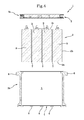
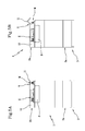
mould 100 for making thelower shell 3a of thecover 3. - The
mould 100 comprises abase plate 101, designed to face theupper surface 2c of the box-shapedbody 2, as well as a first pair oflateral plates 102 which are opposite to each other and a second pair oflateral plates 103 which are also opposite to each other. - One of the two pairs of
lateral plates 102 forms the above-mentioned handles 8. - Preferably, the pair of
lateral plates 102 forming thehandles 8 is uncoupled from thebase plate 101 and can be stably connected to it using threaded elements. - However, preferably, the lateral plates of the
other pair 103 are coupled to thebase plate 101, for example by hinging about respective axes. - In order to make a partial covering of the
lower surface 2a of the box-shapedbody 2 and form the above-mentionedbottom opening 4, themould 100 also comprises one or moreauxiliary plates 104 havingrespective protrusions 104a designed to enter into contact with thelower surface 2a of the box-shapedbody 2. In other words, theprotrusions 104a have an overall size corresponding to the above-mentionedbottom opening 4 in such a way that, after injection, the removal of theauxiliary plates 104 makes thebottom opening 4. - This invention achieves the preset aims.
- The making of the outer cover entirely in rubber constitutes an effective protection against vibrations and/or impacts, thus increasing the working life of the accumulator.
- Moreover, the integral and single-block cover, using rubber, of the lateral surfaces of the box-shaped body allows an efficient screen to be made against adverse weather conditions and/or corrosive substances.
- The use of the rubber also improves in a significant fashion the adherence of the accumulator on any supporting surface, making the positioning more stable and eliminating the need for specific attachment or fitting elements.
- Moreover, the making of lateral handles allows a practical and safe movement of the accumulator by an operator.
- The invention described above is susceptible of industrial application and may be modified and adapted in several ways without thereby departing from the scope of the inventive concept. Moreover, all the details of the invention may be substituted for technically equivalent elements.
Claims (12)
- An electrical accumulator, comprising:- a box-shaped body (2) forming a unit for storing electricity;- an outer cover (3) stably applied to the box-shaped body (2) for surrounding it,characterised in that the outer cover (3) is made of rubber and forms a matrix encapsulating at least a portion of the box-shaped body (2).
- The accumulator according to claim 1, wherein the cover (3) is shaped to match and adheres to at least a part of the outer profile of the box-shaped body (2).
- The accumulator according to claim 1 or 2, wherein the box-shaped body (2) has a lower supporting surface (2a), a lateral surface (2b) and an upper surface (2c), and wherein the cover (3) comprises:- a lower shell (3a) which covers entirely at least the outer corners of the lower surface (2a) and of the lateral surface (2b) of the box-shaped body (2), leaving at least partially free the upper surface (2c) of the box-shaped body (2), and- an upper cover (3b) for closing which can be stably coupled to the lower shell (3a).
- The accumulator according to claim 3, wherein the lower shell (3a) comprises a monolithic piece made from rubber and/or the upper cover (3b) comprises a monolithic piece made from rubber.
- The accumulator according to claim 3 or 4, wherein the cover (3b) comprises a single block made from rubber and has at least a stretch (9) with a linear extension with reduced thickness, positioned between two mutually adjacent portions (10, 11) of the cover (3b); the stretch (9) with reduced thickness forming a planned line of weakness designed to constitute a line for hinging the second portion (11) of the cover to the first portion (10) of the cover.
- The accumulator according to any one of the preceding claims, wherein the rubber comprises a polyurethane mix of isocyanate and polyol.
- The accumulator according to any one of the preceding claims, wherein the box-shaped body (2) is formed by a plurality of batteries (B) placed side by side to form a battery pack (2), and wherein the cover (3) covers entirely at least the outer corners of the battery pack (2).
- The accumulator according to claim 7 when it depends on claim 3, wherein the batteries (B) are shaped in such a way as to form, between them, a plurality of conduits (7) extending between the lower surface (2a) and the upper surface (2c) of the battery pack (2) for the passage of cooling air.
- The accumulator according to claim 8, wherein the cover (3) comprises:- a lower shell (3a) which covers entirely at least the outer corners of the lower surface (2a) and of the lateral surface (2b) of the box-shaped body (2), leaving at least partially free the upper surface (2c) of the box-shaped body (2), and- an upper cover (3b) for closing which can be stably coupled to the lower shell (3a),and wherein the lower shell (3a) has a bottom wall having a bottom opening (4) passing through the bottom wall and facing the conduits (7), the bottom wall also having at least one groove (6) extending between the bottom opening (4) and a lateral surface of the lower shell (3a).
- A process for making an accumulator according to any one of the preceding claims, comprising the following steps:- preparing a box-shaped body (2) forming a unit for storing electricity;- preparing a mould (100);- inserting the box-shaped body (2) in the mould (100);- injecting rubber in the liquid state in the mould (100) and in contact with the box-shaped body (2) in such a way that the rubber coats at least partly the box-shaped body(2).
- The process according to claim 10, wherein the step of injecting the rubber is performed in such a way that the rubber coats at least a part of the bottom surface (2a) and an entire lateral surface (2b) of the box-shaped body (2), leaving at least partly free an upper surface (2c) of the box-shaped body (2).
- The process according to claim 11, also comprising a step of making a cover (3b) for covering the upper surface (2c) of the box-shaped body (2), the step of making the cover (3b) being performed by preparing an auxiliary mould different to the mould (100) used in the previous injecting step, and then injecting rubber in the liquid state in the auxiliary mould.
Priority Applications (1)
| Application Number | Priority Date | Filing Date | Title |
|---|---|---|---|
| EP13174030.0A EP2819206B1 (en) | 2013-06-27 | 2013-06-27 | Electrical accumulator |
Applications Claiming Priority (1)
| Application Number | Priority Date | Filing Date | Title |
|---|---|---|---|
| EP13174030.0A EP2819206B1 (en) | 2013-06-27 | 2013-06-27 | Electrical accumulator |
Publications (2)
| Publication Number | Publication Date |
|---|---|
| EP2819206A1 true EP2819206A1 (en) | 2014-12-31 |
| EP2819206B1 EP2819206B1 (en) | 2018-12-26 |
Family
ID=48874764
Family Applications (1)
| Application Number | Title | Priority Date | Filing Date |
|---|---|---|---|
| EP13174030.0A Not-in-force EP2819206B1 (en) | 2013-06-27 | 2013-06-27 | Electrical accumulator |
Country Status (1)
| Country | Link |
|---|---|
| EP (1) | EP2819206B1 (en) |
Citations (5)
| Publication number | Priority date | Publication date | Assignee | Title |
|---|---|---|---|---|
| US20020015880A1 (en) * | 2000-06-19 | 2002-02-07 | C&D Technologies, Inc. | Molded modular lead-acid battery system |
| US6593027B1 (en) * | 2000-07-27 | 2003-07-15 | Eaton Corporation | Combination battery cover, heat shield and hold down |
| CN2629231Y (en) * | 2003-05-27 | 2004-07-28 | 王铁忠 | Motor vehicle battery thermal insulation apparatus |
| US20120074617A1 (en) * | 2010-09-24 | 2012-03-29 | Bayer Materialscience Ag | Flame-retardant impact-modified battery boxes based on polycarbonate i |
| DE202010017675U1 (en) * | 2010-09-20 | 2012-05-23 | Bmz Batterien-Montage-Zentrum Gmbh | battery assembly |
Family Cites Families (1)
| Publication number | Priority date | Publication date | Assignee | Title |
|---|---|---|---|---|
| KR100686814B1 (en) * | 2005-04-26 | 2007-02-26 | 삼성에스디아이 주식회사 | Polymer battery packs and manufacturing methods thereof |
-
2013
- 2013-06-27 EP EP13174030.0A patent/EP2819206B1/en not_active Not-in-force
Patent Citations (5)
| Publication number | Priority date | Publication date | Assignee | Title |
|---|---|---|---|---|
| US20020015880A1 (en) * | 2000-06-19 | 2002-02-07 | C&D Technologies, Inc. | Molded modular lead-acid battery system |
| US6593027B1 (en) * | 2000-07-27 | 2003-07-15 | Eaton Corporation | Combination battery cover, heat shield and hold down |
| CN2629231Y (en) * | 2003-05-27 | 2004-07-28 | 王铁忠 | Motor vehicle battery thermal insulation apparatus |
| DE202010017675U1 (en) * | 2010-09-20 | 2012-05-23 | Bmz Batterien-Montage-Zentrum Gmbh | battery assembly |
| US20120074617A1 (en) * | 2010-09-24 | 2012-03-29 | Bayer Materialscience Ag | Flame-retardant impact-modified battery boxes based on polycarbonate i |
Also Published As
| Publication number | Publication date |
|---|---|
| EP2819206B1 (en) | 2018-12-26 |
Similar Documents
| Publication | Publication Date | Title |
|---|---|---|
| US10581035B2 (en) | Secondary battery pack | |
| US9991573B2 (en) | Housing device for at least one energy store cell and method for producing an housing device for at least one energy store cell | |
| US9947907B2 (en) | Housing composed of a metal frame structure and a plastic component for accommodating a cell stack | |
| CN102742044B (en) | Battery case for vehicle | |
| US20240157816A1 (en) | Vehicle battery tray and method of manufacturing the same | |
| US9406983B2 (en) | Battery module | |
| EP3644398A1 (en) | Battery module housing having easily reusable, recyclable, and reworkable adhesion structure and battery module comprising same | |
| KR102610042B1 (en) | integrated high voltage junction unit for electric vehicle | |
| US20130177795A1 (en) | Swappable, configurable and structural battery pack for electric vehicles | |
| US5293951A (en) | Battery safety unit and method | |
| US10555425B2 (en) | Enclosure assembly for an electronic controller having an over-molded part to protect electronic components | |
| EP4080673A1 (en) | Battery module comprising removable fuse assembly, and battery pack comprising same | |
| EP3767702A1 (en) | Rechargeable battery | |
| US20220223954A1 (en) | Modular battery housing for mounting battery modules to one of a plurality of electric vehicles | |
| US20200353807A1 (en) | Electric vehicle having a battery in an underfloor arrangement | |
| US11539097B2 (en) | Battery housing for a high-voltage battery of a motor vehicle, high- voltage battery and motor vehicle | |
| US9056589B2 (en) | Rear windshield comprising electrics protection box | |
| US11855300B2 (en) | Electric vehicle battery pack having external side pouch for electrical components | |
| US20200152933A1 (en) | Battery for an electric drive of a motor vehicle | |
| EP2819206B1 (en) | Electrical accumulator | |
| CN214971366U (en) | Battery module and battery pack | |
| CN114069147B (en) | Battery and associated vehicle | |
| WO2024249939A1 (en) | Modular vehicle multi-plane chassis system | |
| CN206753270U (en) | It is a kind of for the shell structure of lock, lock and vehicle | |
| US5246793A (en) | Battery safety unit |
Legal Events
| Date | Code | Title | Description |
|---|---|---|---|
| PUAI | Public reference made under article 153(3) epc to a published international application that has entered the european phase |
Free format text: ORIGINAL CODE: 0009012 |
|
| 17P | Request for examination filed |
Effective date: 20130627 |
|
| AK | Designated contracting states |
Kind code of ref document: A1 Designated state(s): AL AT BE BG CH CY CZ DE DK EE ES FI FR GB GR HR HU IE IS IT LI LT LU LV MC MK MT NL NO PL PT RO RS SE SI SK SM TR |
|
| AX | Request for extension of the european patent |
Extension state: BA ME |
|
| R17P | Request for examination filed (corrected) |
Effective date: 20150629 |
|
| RBV | Designated contracting states (corrected) |
Designated state(s): AL AT BE BG CH CY CZ DE DK EE ES FI FR GB GR HR HU IE IS IT LI LT LU LV MC MK MT NL NO PL PT RO RS SE SI SK SM TR |
|
| 17Q | First examination report despatched |
Effective date: 20151020 |
|
| GRAP | Despatch of communication of intention to grant a patent |
Free format text: ORIGINAL CODE: EPIDOSNIGR1 |
|
| STAA | Information on the status of an ep patent application or granted ep patent |
Free format text: STATUS: GRANT OF PATENT IS INTENDED |
|
| RIC1 | Information provided on ipc code assigned before grant |
Ipc: H01M 2/30 20060101ALI20180628BHEP Ipc: B29C 45/00 20060101ALI20180628BHEP Ipc: H01M 10/42 20060101ALN20180628BHEP Ipc: H01M 10/06 20060101ALI20180628BHEP Ipc: H01M 10/647 20140101ALI20180628BHEP Ipc: H01M 2/04 20060101AFI20180628BHEP Ipc: H01M 10/6562 20140101ALI20180628BHEP Ipc: H01M 10/6557 20140101ALI20180628BHEP Ipc: H01M 10/625 20140101ALI20180628BHEP Ipc: B29C 45/14 20060101ALI20180628BHEP Ipc: H01M 10/613 20140101ALI20180628BHEP Ipc: H01M 2/10 20060101ALI20180628BHEP Ipc: B29K 21/00 20060101ALI20180628BHEP |
|
| RIC1 | Information provided on ipc code assigned before grant |
Ipc: H01M 10/625 20140101ALI20180704BHEP Ipc: H01M 2/04 20060101AFI20180704BHEP Ipc: H01M 10/647 20140101ALI20180704BHEP Ipc: B29K 21/00 20060101ALI20180704BHEP Ipc: H01M 10/6562 20140101ALI20180704BHEP Ipc: H01M 2/30 20060101ALI20180704BHEP Ipc: B29C 45/00 20060101ALI20180704BHEP Ipc: H01M 2/10 20060101ALI20180704BHEP Ipc: H01M 10/613 20140101ALI20180704BHEP Ipc: H01M 10/6557 20140101ALI20180704BHEP Ipc: H01M 10/06 20060101ALI20180704BHEP Ipc: H01M 10/42 20060101ALN20180704BHEP Ipc: B29C 45/14 20060101ALI20180704BHEP |
|
| INTG | Intention to grant announced |
Effective date: 20180725 |
|
| GRAS | Grant fee paid |
Free format text: ORIGINAL CODE: EPIDOSNIGR3 |
|
| GRAA | (expected) grant |
Free format text: ORIGINAL CODE: 0009210 |
|
| STAA | Information on the status of an ep patent application or granted ep patent |
Free format text: STATUS: THE PATENT HAS BEEN GRANTED |
|
| AK | Designated contracting states |
Kind code of ref document: B1 Designated state(s): AL AT BE BG CH CY CZ DE DK EE ES FI FR GB GR HR HU IE IS IT LI LT LU LV MC MK MT NL NO PL PT RO RS SE SI SK SM TR |
|
| REG | Reference to a national code |
Ref country code: GB Ref legal event code: FG4D |
|
| REG | Reference to a national code |
Ref country code: CH Ref legal event code: EP |
|
| REG | Reference to a national code |
Ref country code: DE Ref legal event code: R096 Ref document number: 602013048673 Country of ref document: DE |
|
| REG | Reference to a national code |
Ref country code: AT Ref legal event code: REF Ref document number: 1082655 Country of ref document: AT Kind code of ref document: T Effective date: 20190115 |
|
| REG | Reference to a national code |
Ref country code: IE Ref legal event code: FG4D |
|
| PG25 | Lapsed in a contracting state [announced via postgrant information from national office to epo] |
Ref country code: FI Free format text: LAPSE BECAUSE OF FAILURE TO SUBMIT A TRANSLATION OF THE DESCRIPTION OR TO PAY THE FEE WITHIN THE PRESCRIBED TIME-LIMIT Effective date: 20181226 Ref country code: BG Free format text: LAPSE BECAUSE OF FAILURE TO SUBMIT A TRANSLATION OF THE DESCRIPTION OR TO PAY THE FEE WITHIN THE PRESCRIBED TIME-LIMIT Effective date: 20190326 Ref country code: LV Free format text: LAPSE BECAUSE OF FAILURE TO SUBMIT A TRANSLATION OF THE DESCRIPTION OR TO PAY THE FEE WITHIN THE PRESCRIBED TIME-LIMIT Effective date: 20181226 Ref country code: HR Free format text: LAPSE BECAUSE OF FAILURE TO SUBMIT A TRANSLATION OF THE DESCRIPTION OR TO PAY THE FEE WITHIN THE PRESCRIBED TIME-LIMIT Effective date: 20181226 Ref country code: NO Free format text: LAPSE BECAUSE OF FAILURE TO SUBMIT A TRANSLATION OF THE DESCRIPTION OR TO PAY THE FEE WITHIN THE PRESCRIBED TIME-LIMIT Effective date: 20190326 Ref country code: LT Free format text: LAPSE BECAUSE OF FAILURE TO SUBMIT A TRANSLATION OF THE DESCRIPTION OR TO PAY THE FEE WITHIN THE PRESCRIBED TIME-LIMIT Effective date: 20181226 |
|
| REG | Reference to a national code |
Ref country code: NL Ref legal event code: MP Effective date: 20181226 |
|
| REG | Reference to a national code |
Ref country code: LT Ref legal event code: MG4D |
|
| PG25 | Lapsed in a contracting state [announced via postgrant information from national office to epo] |
Ref country code: GR Free format text: LAPSE BECAUSE OF FAILURE TO SUBMIT A TRANSLATION OF THE DESCRIPTION OR TO PAY THE FEE WITHIN THE PRESCRIBED TIME-LIMIT Effective date: 20190327 Ref country code: RS Free format text: LAPSE BECAUSE OF FAILURE TO SUBMIT A TRANSLATION OF THE DESCRIPTION OR TO PAY THE FEE WITHIN THE PRESCRIBED TIME-LIMIT Effective date: 20181226 Ref country code: AL Free format text: LAPSE BECAUSE OF FAILURE TO SUBMIT A TRANSLATION OF THE DESCRIPTION OR TO PAY THE FEE WITHIN THE PRESCRIBED TIME-LIMIT Effective date: 20181226 Ref country code: SE Free format text: LAPSE BECAUSE OF FAILURE TO SUBMIT A TRANSLATION OF THE DESCRIPTION OR TO PAY THE FEE WITHIN THE PRESCRIBED TIME-LIMIT Effective date: 20181226 |
|
| REG | Reference to a national code |
Ref country code: AT Ref legal event code: MK05 Ref document number: 1082655 Country of ref document: AT Kind code of ref document: T Effective date: 20181226 |
|
| PG25 | Lapsed in a contracting state [announced via postgrant information from national office to epo] |
Ref country code: NL Free format text: LAPSE BECAUSE OF FAILURE TO SUBMIT A TRANSLATION OF THE DESCRIPTION OR TO PAY THE FEE WITHIN THE PRESCRIBED TIME-LIMIT Effective date: 20181226 |
|
| PG25 | Lapsed in a contracting state [announced via postgrant information from national office to epo] |
Ref country code: IT Free format text: LAPSE BECAUSE OF FAILURE TO SUBMIT A TRANSLATION OF THE DESCRIPTION OR TO PAY THE FEE WITHIN THE PRESCRIBED TIME-LIMIT Effective date: 20181226 Ref country code: ES Free format text: LAPSE BECAUSE OF FAILURE TO SUBMIT A TRANSLATION OF THE DESCRIPTION OR TO PAY THE FEE WITHIN THE PRESCRIBED TIME-LIMIT Effective date: 20181226 Ref country code: CZ Free format text: LAPSE BECAUSE OF FAILURE TO SUBMIT A TRANSLATION OF THE DESCRIPTION OR TO PAY THE FEE WITHIN THE PRESCRIBED TIME-LIMIT Effective date: 20181226 Ref country code: PT Free format text: LAPSE BECAUSE OF FAILURE TO SUBMIT A TRANSLATION OF THE DESCRIPTION OR TO PAY THE FEE WITHIN THE PRESCRIBED TIME-LIMIT Effective date: 20190426 Ref country code: PL Free format text: LAPSE BECAUSE OF FAILURE TO SUBMIT A TRANSLATION OF THE DESCRIPTION OR TO PAY THE FEE WITHIN THE PRESCRIBED TIME-LIMIT Effective date: 20181226 |
|
| PG25 | Lapsed in a contracting state [announced via postgrant information from national office to epo] |
Ref country code: SM Free format text: LAPSE BECAUSE OF FAILURE TO SUBMIT A TRANSLATION OF THE DESCRIPTION OR TO PAY THE FEE WITHIN THE PRESCRIBED TIME-LIMIT Effective date: 20181226 Ref country code: SK Free format text: LAPSE BECAUSE OF FAILURE TO SUBMIT A TRANSLATION OF THE DESCRIPTION OR TO PAY THE FEE WITHIN THE PRESCRIBED TIME-LIMIT Effective date: 20181226 Ref country code: IS Free format text: LAPSE BECAUSE OF FAILURE TO SUBMIT A TRANSLATION OF THE DESCRIPTION OR TO PAY THE FEE WITHIN THE PRESCRIBED TIME-LIMIT Effective date: 20190426 Ref country code: RO Free format text: LAPSE BECAUSE OF FAILURE TO SUBMIT A TRANSLATION OF THE DESCRIPTION OR TO PAY THE FEE WITHIN THE PRESCRIBED TIME-LIMIT Effective date: 20181226 |
|
| REG | Reference to a national code |
Ref country code: DE Ref legal event code: R097 Ref document number: 602013048673 Country of ref document: DE |
|
| PG25 | Lapsed in a contracting state [announced via postgrant information from national office to epo] |
Ref country code: DK Free format text: LAPSE BECAUSE OF FAILURE TO SUBMIT A TRANSLATION OF THE DESCRIPTION OR TO PAY THE FEE WITHIN THE PRESCRIBED TIME-LIMIT Effective date: 20181226 Ref country code: AT Free format text: LAPSE BECAUSE OF FAILURE TO SUBMIT A TRANSLATION OF THE DESCRIPTION OR TO PAY THE FEE WITHIN THE PRESCRIBED TIME-LIMIT Effective date: 20181226 |
|
| PLBE | No opposition filed within time limit |
Free format text: ORIGINAL CODE: 0009261 |
|
| STAA | Information on the status of an ep patent application or granted ep patent |
Free format text: STATUS: NO OPPOSITION FILED WITHIN TIME LIMIT |
|
| 26N | No opposition filed |
Effective date: 20190927 |
|
| REG | Reference to a national code |
Ref country code: DE Ref legal event code: R119 Ref document number: 602013048673 Country of ref document: DE |
|
| PG25 | Lapsed in a contracting state [announced via postgrant information from national office to epo] |
Ref country code: MC Free format text: LAPSE BECAUSE OF FAILURE TO SUBMIT A TRANSLATION OF THE DESCRIPTION OR TO PAY THE FEE WITHIN THE PRESCRIBED TIME-LIMIT Effective date: 20181226 |
|
| REG | Reference to a national code |
Ref country code: CH Ref legal event code: PL |
|
| GBPC | Gb: european patent ceased through non-payment of renewal fee |
Effective date: 20190627 |
|
| PG25 | Lapsed in a contracting state [announced via postgrant information from national office to epo] |
Ref country code: SI Free format text: LAPSE BECAUSE OF FAILURE TO SUBMIT A TRANSLATION OF THE DESCRIPTION OR TO PAY THE FEE WITHIN THE PRESCRIBED TIME-LIMIT Effective date: 20181226 |
|
| REG | Reference to a national code |
Ref country code: BE Ref legal event code: MM Effective date: 20190630 |
|
| PG25 | Lapsed in a contracting state [announced via postgrant information from national office to epo] |
Ref country code: TR Free format text: LAPSE BECAUSE OF FAILURE TO SUBMIT A TRANSLATION OF THE DESCRIPTION OR TO PAY THE FEE WITHIN THE PRESCRIBED TIME-LIMIT Effective date: 20181226 |
|
| PG25 | Lapsed in a contracting state [announced via postgrant information from national office to epo] |
Ref country code: IE Free format text: LAPSE BECAUSE OF NON-PAYMENT OF DUE FEES Effective date: 20190627 Ref country code: GB Free format text: LAPSE BECAUSE OF NON-PAYMENT OF DUE FEES Effective date: 20190627 Ref country code: DE Free format text: LAPSE BECAUSE OF NON-PAYMENT OF DUE FEES Effective date: 20200101 |
|
| PG25 | Lapsed in a contracting state [announced via postgrant information from national office to epo] |
Ref country code: CH Free format text: LAPSE BECAUSE OF NON-PAYMENT OF DUE FEES Effective date: 20190630 Ref country code: LU Free format text: LAPSE BECAUSE OF NON-PAYMENT OF DUE FEES Effective date: 20190627 Ref country code: LI Free format text: LAPSE BECAUSE OF NON-PAYMENT OF DUE FEES Effective date: 20190630 Ref country code: BE Free format text: LAPSE BECAUSE OF NON-PAYMENT OF DUE FEES Effective date: 20190630 |
|
| PG25 | Lapsed in a contracting state [announced via postgrant information from national office to epo] |
Ref country code: FR Free format text: LAPSE BECAUSE OF NON-PAYMENT OF DUE FEES Effective date: 20190630 |
|
| PG25 | Lapsed in a contracting state [announced via postgrant information from national office to epo] |
Ref country code: CY Free format text: LAPSE BECAUSE OF FAILURE TO SUBMIT A TRANSLATION OF THE DESCRIPTION OR TO PAY THE FEE WITHIN THE PRESCRIBED TIME-LIMIT Effective date: 20181226 |
|
| PG25 | Lapsed in a contracting state [announced via postgrant information from national office to epo] |
Ref country code: EE Free format text: LAPSE BECAUSE OF NON-PAYMENT OF DUE FEES Effective date: 20181226 |
|
| PG25 | Lapsed in a contracting state [announced via postgrant information from national office to epo] |
Ref country code: HU Free format text: LAPSE BECAUSE OF FAILURE TO SUBMIT A TRANSLATION OF THE DESCRIPTION OR TO PAY THE FEE WITHIN THE PRESCRIBED TIME-LIMIT; INVALID AB INITIO Effective date: 20130627 Ref country code: MT Free format text: LAPSE BECAUSE OF FAILURE TO SUBMIT A TRANSLATION OF THE DESCRIPTION OR TO PAY THE FEE WITHIN THE PRESCRIBED TIME-LIMIT Effective date: 20181226 |
|
| PG25 | Lapsed in a contracting state [announced via postgrant information from national office to epo] |
Ref country code: MK Free format text: LAPSE BECAUSE OF FAILURE TO SUBMIT A TRANSLATION OF THE DESCRIPTION OR TO PAY THE FEE WITHIN THE PRESCRIBED TIME-LIMIT Effective date: 20181226 |