EP2819139A1 - Switch unit - Google Patents
Switch unit Download PDFInfo
- Publication number
- EP2819139A1 EP2819139A1 EP14169621.1A EP14169621A EP2819139A1 EP 2819139 A1 EP2819139 A1 EP 2819139A1 EP 14169621 A EP14169621 A EP 14169621A EP 2819139 A1 EP2819139 A1 EP 2819139A1
- Authority
- EP
- European Patent Office
- Prior art keywords
- gasket
- case
- pressing member
- terminals
- holes
- Prior art date
- Legal status (The legal status is an assumption and is not a legal conclusion. Google has not performed a legal analysis and makes no representation as to the accuracy of the status listed.)
- Granted
Links
Images




Classifications
-
- H—ELECTRICITY
- H01—ELECTRIC ELEMENTS
- H01H—ELECTRIC SWITCHES; RELAYS; SELECTORS; EMERGENCY PROTECTIVE DEVICES
- H01H13/00—Switches having rectilinearly-movable operating part or parts adapted for pushing or pulling in one direction only, e.g. push-button switch
- H01H13/02—Details
- H01H13/04—Cases; Covers
- H01H13/06—Dustproof, splashproof, drip-proof, waterproof or flameproof casings
-
- H—ELECTRICITY
- H01—ELECTRIC ELEMENTS
- H01H—ELECTRIC SWITCHES; RELAYS; SELECTORS; EMERGENCY PROTECTIVE DEVICES
- H01H9/00—Details of switching devices, not covered by groups H01H1/00 - H01H7/00
- H01H9/02—Bases, casings, or covers
- H01H9/04—Dustproof, splashproof, drip-proof, waterproof, or flameproof casings
-
- H—ELECTRICITY
- H01—ELECTRIC ELEMENTS
- H01H—ELECTRIC SWITCHES; RELAYS; SELECTORS; EMERGENCY PROTECTIVE DEVICES
- H01H1/00—Contacts
- H01H1/58—Electric connections to or between contacts; Terminals
-
- H—ELECTRICITY
- H01—ELECTRIC ELEMENTS
- H01H—ELECTRIC SWITCHES; RELAYS; SELECTORS; EMERGENCY PROTECTIVE DEVICES
- H01H13/00—Switches having rectilinearly-movable operating part or parts adapted for pushing or pulling in one direction only, e.g. push-button switch
- H01H13/02—Details
- H01H13/04—Cases; Covers
- H01H13/08—Casing of switch constituted by a handle serving a purpose other than the actuation of the switch
-
- H—ELECTRICITY
- H01—ELECTRIC ELEMENTS
- H01H—ELECTRIC SWITCHES; RELAYS; SELECTORS; EMERGENCY PROTECTIVE DEVICES
- H01H2223/00—Casings
- H01H2223/002—Casings sealed
-
- H—ELECTRICITY
- H01—ELECTRIC ELEMENTS
- H01H—ELECTRIC SWITCHES; RELAYS; SELECTORS; EMERGENCY PROTECTIVE DEVICES
- H01H9/00—Details of switching devices, not covered by groups H01H1/00 - H01H7/00
- H01H9/02—Bases, casings, or covers
- H01H9/06—Casing of switch constituted by a handle serving a purpose other than the actuation of the switch, e.g. by the handle of a vacuum cleaner
Definitions
- a trigger switch includes a case provided with a switch and an operation part used to operate the switch.
- the switch is turned on and off by pressing the operation part (trigger) onto an inside of the case.
- a trigger switch controls a power supplied to a motor of an electric power tool.
- the trigger switch is connected to the motor outside the case by a lead wire. Liquid-tightness (a property preventing the invasion of liquid) at a connection point to the lead wire is required for the case in order to prevent invasion of a liquid streaming on the lead wire.
- the case may be constructed by a combination of two casing members, and the opening may be formed between the casing members.
- Terminal unit 3 includes external terminals 4a and 4b and pressing member 5.
- each of external terminals 4a and 4b is a terminal to which a lead wire connected to a motor of the electric power tool is to be connected, and external terminals 4a and 4b are projected to the outside of case 2.
- External terminals 4a and 4b are symmetrically located with respect to pressing member 5.
- external terminals 4a and 4b are connected to electric components such as the switch and the wiring board.
- External terminals 4a and 4b include holes 4d and 4e, respectively. In each of holes 4d and 4e, a bolt is inserted through a plate-like portion to which the lead wire is connected. External terminal 4a also includes positioning hole 4c made at a position that comes into contact with base member 7. External terminals 4a and 4b have conductivity, and are made of metal, for example. In this embodiment, each of external terminals 4a and 4b is formed by bending a sheet metal.
- Gasket 8 has a planar shape, and is an insulating seal member (packing) made of an elastic material such as rubber.
- Gasket 8 includes through-hole 8a through which external terminal 4a extends and through-hole 8b through which external terminal 4b extends.
- Through-holes 8a and 8b have rectangular shapes so as to fit to sectional shapes of external terminals 4a and 4b inserted therethrough.
- Gasket 8 also includes positioning hole 8c between through-holes 8a and 8b.
- Pressing member 5 is a block having an insulating property, and is made of plastic, for example. Pressing member 5 includes recesses 5a so that nut 9 is accommodated in each side surface. Pressing member 5 includes a planar surface on the lower side in order to press a central portion of gasket 8. Pressing member 5 includes projections 5c for combining with casing members 2a and 2b.
- Fig. 9 is a plan view illustrating the configuration of gasket 8.
- region 8d between through-holes 8a and 8b is pressed against the planar lower surface of pressing member 5.
- region 8e including the regions outward from through-holes 8a and 8b are pressed against inside surfaces of casing members 2a and 2b (case 2). Because the surroundings of through-holes 8a and 8b in gasket 8 are pressed by pressing member 5 and case 2, the liquid streaming on external terminals 4a and 4b cannot stream on the surface of gasket 8.
Landscapes
- Push-Button Switches (AREA)
- Switch Cases, Indication, And Locking (AREA)
- Portable Power Tools In General (AREA)
- Gasket Seals (AREA)
Abstract
Description
- The present invention relates to a switch unit.
- Conventionally, a trigger switch includes a case provided with a switch and an operation part used to operate the switch. For example, the switch is turned on and off by pressing the operation part (trigger) onto an inside of the case. For example, a trigger switch controls a power supplied to a motor of an electric power tool. The trigger switch is connected to the motor outside the case by a lead wire. Liquid-tightness (a property preventing the invasion of liquid) at a connection point to the lead wire is required for the case in order to prevent invasion of a liquid streaming on the lead wire.
- Japanese Unexamined Patent Publication No.
2012-206248 2012-206248 2012-206248 - However, in the conventional technologies, unfortunately workability is degraded because of many man-hours.
- Time waiting for the filled or applied adhesive to be cured is required in the configuration in which the portion through which the lead wire is drawn is filled with the adhesive. Therefore, assembly workability of the trigger switch is degraded. A method for connecting the motor and the lead wire is restricted because the specific lead wire is caused to adhere to the trigger switch.
- In the configuration in which the motor connection terminal is covered with the packing, after the lead wire is connected to the motor connection terminal, it is necessary to thread the lead wire through the packing to attach the packing to the trigger switch. Therefore, assembly man-hours increase in order to combine the trigger switch and the motor.
- An object of the present invention is to construct a switch unit that has the good assembly workability and the liquid-tightness at the position where the external connection terminal of the case is located.
- A switch unit of the present invention includes a case, two terminals, a gasket, a base member, and a pressing member. The case includes an opening and a switch. The two terminals partially project to an outside of the case from the opening. The gasket is configured to seal the opening and includes two through-holes through which the terminals extend. The pressing member is arranged between the terminals. In the switch unit, the through-holes are in close contact with surroundings of the piercing terminals. A region between the through-holes of the gasket is pressed while nipped between the pressing member and the base member. A surrounding region in the gasket is pressed while nipped between an inside surface of the case and the base member.
- According to the configuration, the two terminals projecting from the case are arranged in the opening, so that a degree of freedom in design of the case and the assembly workability can be improved. The region between the through-holes in the gasket is pressed by the pressing member, and the surrounding region in the gasket is pressed by the inside surface of the case. The surrounding region is the region outward from the through-holes and outward from the region between the through-holes. Therefore, the state in which the through-holes of the gasket are in close contact with the terminals piecing therethrough can be maintained. Accordingly, the liquid-tightness of the case can be ensured even if two terminals separated from each other are arranged in one opening of the case.
- In the switch unit, two side surfaces opposed to each other in the gasket may be pressed by the case.
- According to the configuration, the two side surfaces opposed to each other in the gasket are pressed by the case, the through-holes come into close contact with the terminals. For example, the case presses the side surfaces of the gasket toward the center direction of the gasket from the sides of the gasket.
- In the switch unit, side surfaces of all walls in the gasket may be pressed by the case.
- In the switch unit, the case may be constructed by a combination of two casing members, and the opening may be formed between the casing members.
- In the switch unit, a terminal unit may be an assembly including the two terminals, the gasket, the base member, and the pressing member. The gasket may have a plate-like shape, and the terminal unit may be assembled in the casing members by sliding the terminal unit in parallel with a planar surface of the gasket.
- According to the configuration, the assembled terminal unit may be assembled in the casing members by sliding the terminal unit, so that the assembly workability can be improved.
- In the switch unit, a height of at least the base member and the gasket overlapping each other may be restricted in a space in the casing members in which the terminal unit is arranged.
- According to the configuration, the height of the base member and the gasket overlapping each other is restricted. Therefore, the gasket is pressed in a manner such that the terminal unit is arranged in the casing members by sliding the terminal unit.
- In the switch unit, the pressing member may include a projection, and an edge of the opening of the case may press the projection of the pressing member against the gasket side.
- According to the present invention, the liquid-tightness of the case can be ensured while the assembly workability is improved.
-
-
Fig. 1 is a perspective view illustrating a configuration of a trigger switch according to an embodiment of the present invention; -
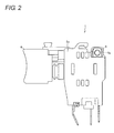
Fig. 2 is a front elevation illustrating the configuration of the trigger switch; -
Fig. 3 is an exploded perspective view illustrating a configuration of a terminal unit of the trigger switch; -
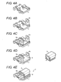
Figs. 4A to 4E are perspective views illustrating an assembly procedure of the terminal unit; -
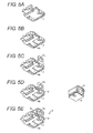
Figs. 5A to 5E are perspective views illustrating an assembly procedure of the terminal unit; -
Fig. 6 is a side view illustrating a configuration of the trigger switch; -
Fig. 7 is a sectional view taken in line A-A ofFig. 6 ; -
Fig. 8 is a sectional view taken in line B-B ofFig. 6 ; -
Fig. 9 is a plan view illustrating a configuration of a gasket of the trigger switch; and -
Fig. 10 is a perspective view illustrating an assembly in which only a pressing member and nuts are excluded from the trigger switch. - Hereinafter, an embodiment of the present invention will be described in detail with reference to the drawings.
-
Fig. 1 is a perspective view illustrating a configuration oftrigger switch 1 according to an embodiment of the present invention.Fig. 2 is a front elevation illustrating the configuration oftrigger switch 1. Trigger switch 1 (switch unit) includescase 2,terminal unit 3, and operation part 6 (trigger). Incase 2, a switch and a wiring board connected to the switch are incorporated. Operation part 6 (trigger) is for switching the switch between on and off from the outside ofcase 2. For example, triggerswitch 1 is configured as a switch unit to be assembled in an electric power tool.Case 2 is configured by a combination ofcasing members -
Terminal unit 3 includesexternal terminals member 5. For example, each ofexternal terminals external terminals case 2.External terminals member 5. Incase 2,external terminals - For example, in the case that the electric power tool is used in the rain, possibly a liquid (water) reaches
external terminals trigger switch 1 through the lead wire connected to the motor. Therefore, there is a need to prevent the liquid from invading incase 2 fromexternal terminals case 2. The switch unit can be used in not only the electric power tool but also other electric devices. -
Fig. 3 is an exploded perspective view illustrating a configuration ofterminal unit 3.Terminal unit 3 is an assembly in which twoexternal terminals base member 7,gasket 8, pressingmember 5, and twonuts 9 are combined. -
External terminals holes holes External terminal 4a also includespositioning hole 4c made at a position that comes into contact withbase member 7.External terminals external terminals -
Base member 7 includeshole 7b through whichexternal terminal 4b is inserted andpositioning pin 7c.Pin 7c includes a groove in which pressingmember 5 is temporarily fixed to a side surface of a column. For example,base member 7 has conductivity, and is made of plastic, for example. -
Gasket 8 has a planar shape, and is an insulating seal member (packing) made of an elastic material such as rubber.Gasket 8 includes through-hole 8a through whichexternal terminal 4a extends and through-hole 8b through whichexternal terminal 4b extends. Through-holes external terminals Gasket 8 also includespositioning hole 8c between through-holes - Pressing
member 5 is a block having an insulating property, and is made of plastic, for example. Pressingmember 5 includesrecesses 5a so thatnut 9 is accommodated in each side surface. Pressingmember 5 includes a planar surface on the lower side in order to press a central portion ofgasket 8. Pressingmember 5 includesprojections 5c for combining withcasing members - The assembly of
terminal unit 3 will be described with reference toFigs. 3 to 5E .Figs. 4A to 4E and5A to 5E are perspective views illustrating an assembly procedure ofterminal unit 3.Figs. 4A to 4E are perspective views illustratingbase member 7 viewed from above.Figs. 5A to 5E are perspective views illustratingbase member 7 viewed from below.External terminal 4b is first inserted throughhole 7b ofbase member 7 from the lower side ofbase member 7, so thatexternal terminal 4b andbase member 7 are combined (Figs. 4B and5B ).External terminal 4a is arranged abovebase member 7 such thatpin 7c ofbase member 7 is inserted throughhole 4c ofexternal terminal 4a (Figs. 4C and5C ).Gasket 8 coversexternal terminals base member 7 such thatexternal terminals holes Figs. 4D and5D ). Pressingmember 5 in whichnuts 9 are assembled inrecesses 5a on both the side surfaces is arranged betweenexternal terminals Figs. 4E and5E ). Pressingmember 5 includes a notch in a lower surface thereof.Pin 7c in which the groove is formed is fitted in the notch to tentatively fix pressingmember 5 tobase member 7.Terminal unit 3 can be dealt with as one unit without being broken down. Therefore,terminal unit 3 facilitates the assembly oftrigger switch 1. Becausenuts 9 are located on the backsides ofholes 4c ofexternal terminals external terminals -
Fig. 6 is a side view illustrating the configuration oftrigger switch 1.Fig. 7 is a sectional view taken in line A-A ofFig. 6 .Terminal unit 3 is attached to casingmember 2b by slidably insertingterminal unit 3 in opening 2ccasing member 2b (or casingmember 2a) from the side surface of casingmember 2b.Casing member 2a as another casing member is combined by sliding ontocasing member 2b andterminal unit 3, which allowscase 2 andterminal unit 3 to be assembled. - Each of
casing members projection 2e (an edge of the opening) engagingprojection 5c of pressingmember 5. A space incasing members terminal unit 3 is arranged) is set such that a height ofterminal unit 3 arranged inside is restricted. The height of at leastbase member 7 andgasket 8 overlapping each other is restricted. Specifically, the height ofbase member 7,external terminal 4a,gasket 8, andprojection 5c of pressingmember 5 overlapping one another is restricted. Therefore,projections 2e ofcasing members projections 5c of pressingmember 5. Therefore, pressingmember 5 is pressed againstgasket 8 by casingmembers terminal unit 3 is slid such thatprojections 2e ofcasing members member 5, wherebyterminal unit 3 combines withcasing member 2b. -
Fig. 8 is a sectional view taken in line B-B ofFig. 6 .Fig. 8 illustrates the section wheregasket 8 is located. When the two side surfaces opposed to each other ingasket 8 are pressed toward the central direction bycase 2, through-holes gasket 8 come into close contact withexternal terminals holes gasket 8 are pressed toward the central direction ofgasket 8 from a surrounding area by casingmembers holes gasket 8 come into close contact withexternal terminals external terminals case 2 through through-holes gasket 8.Hole 8c ofgasket 8 also comes into close contact withpin 7c piercing therethrough from all around. - The planar lower surface of pressing
member 5 presses the central portion of the upper surface ofgasket 8 such that the central portion ofgasket 8 does not float due to deformation ofgasket 8. Regions outward from through-holes gasket 8 are pressed by casingmembers -
Fig. 9 is a plan view illustrating the configuration ofgasket 8. Whenterminal unit 3 is assembled incase 2,region 8d between through-holes member 5. In the upper surface ofgasket 8,surrounding region 8e including the regions outward from through-holes casing members holes gasket 8 are pressed by pressingmember 5 andcase 2, the liquid streaming onexternal terminals gasket 8. -
Fig. 10 is a perspective view illustrating the assembly in which only pressingmember 5 andnuts 9 are excluded (are not illustrated) fromtrigger switch 1 for the purpose of the description of opening 2c. Opening 2c is formed betweencasing members external terminals case 2 from opening 2c in assembledtrigger switch 1. Therefore, walls ofcasing members external terminals gasket 8. - The positions of
external terminals trigger switch 1 is to be connected or for the sake of assembly of a molding product. Therefore, sometimes the two openings fit to the sectional shapes of the external terminals cannot be provided in the case. - On the other hand, two
external terminals terminal unit 3 assembled as one unit component can be assembled incasing members terminal unit 3 in parallel with the upper surface (planar surface) of plate-like gasket 8. Therefore, an assembly procedure can be simplified to improve the assembly workability. No gap is formed byexternal terminals 4a and 4band through-holes gasket 8 in a manner such that the region betweenexternal terminals gasket 8 by pressingmember 5. Therefore, the liquid-tightness can be ensured at the positions whereexternal terminals switch 1 of the embodiment has good assembly workability as well as the liquid-tightness at the positions whereexternal terminals - The present invention is not limited to the embodiment, but various changes can be made without departing from the scope of the invention. An embodiment obtained by a proper combination of the disclosed technical means is also included in the technical scope of the invention.
- The present invention can be applied to a trigger switch of an electric power tool.
- Although the invention has been described in detail for the purpose of illustration based on what is currently considered to be the most practical and preferred embodiments, it is to be understood that such detail is solely for that purpose and that the invention is not limited to the disclosed embodiments, but, on the contrary, is intended to cover modifications and equivalent arrangements that are within the spirit and scope of the appended claims. For example, it is to be understood that the present invention contemplates that, to the extent possible, one or more features of any embodiment can be combined with one or more features of any other embodiment.
Claims (7)
- A switch unit comprising:a case (2) that comprises an opening (2c) and a switch (1);two terminals (4a and 4b) that partially project to an outside of the case (2) from the opening (2c);a gasket (8) configured to seal the opening (2c), the gasket (8) comprising two through-holes (8a and 8b) through which the terminals (4a and 4b) extend;a base member (7); anda pressing member (5) that is arranged between the terminals (4a and 4b),wherein the gasket (8) is in close contact with the terminals (4a and 4b) at the through-holes (8a and 8b),a region between the through-holes (8a and 8b) of the gasket (8) is pressed while nipped between the pressing member (5) and the base member (7), anda surrounding region in the gasket (8) is pressed while nipped between an inside surface of the case (2) and the base member (7).
- The switch unit according to claim 1, wherein two side surfaces opposed to each other in the gasket (8) are pressed by the case (2).
- The switch unit according to claim 1 or 2, wherein side surfaces of all walls in the gasket (8) are pressed by the case (2).
- The switch unit according to any one of claims 1 to 3,
wherein the case (2) is constructed by a combination of two casing members (2a and 2b), and
the opening (2c) is formed between the casing members (2a and 2b). - The switch unit according to claim 4,
wherein a terminal unit (3) is an assembly comprising the two terminals (4a and 4b), the gasket (8), the base member (7), and the pressing member (5),
the gasket (8) has a plate-like shape, and
the terminal unit (3) is assembled in the casing members (2a and 2b) by sliding the terminal unit (3) in parallel with a planar surface of the gasket (8). - The switch unit according to claim 5, wherein a height of at least the base member (7) and the gasket (8) overlapping each other is restricted in a space in the casing members (2a and 2b) in which the terminal unit (3) is arranged.
- The switch unit according to any one of claims 1 tor 6,
wherein the pressing member (5) comprises a projection (5c), and
an edge of the opening (2c) of the case (2) presses the projection (5c) of the pressing member (5) against the gasket side.
Applications Claiming Priority (1)
| Application Number | Priority Date | Filing Date | Title |
|---|---|---|---|
| JP2013135456A JP6160303B2 (en) | 2013-06-27 | 2013-06-27 | Switch unit |
Publications (2)
| Publication Number | Publication Date |
|---|---|
| EP2819139A1 true EP2819139A1 (en) | 2014-12-31 |
| EP2819139B1 EP2819139B1 (en) | 2020-08-05 |
Family
ID=50884205
Family Applications (1)
| Application Number | Title | Priority Date | Filing Date |
|---|---|---|---|
| EP14169621.1A Active EP2819139B1 (en) | 2013-06-27 | 2014-05-23 | Switch unit |
Country Status (4)
| Country | Link |
|---|---|
| US (1) | US9373461B2 (en) |
| EP (1) | EP2819139B1 (en) |
| JP (1) | JP6160303B2 (en) |
| CN (2) | CN104252983B (en) |
Cited By (1)
| Publication number | Priority date | Publication date | Assignee | Title |
|---|---|---|---|---|
| EP2889887A1 (en) * | 2013-12-27 | 2015-07-01 | Omron Corporation | Terminal connection structure |
Families Citing this family (3)
| Publication number | Priority date | Publication date | Assignee | Title |
|---|---|---|---|---|
| JP6160303B2 (en) * | 2013-06-27 | 2017-07-12 | オムロン株式会社 | Switch unit |
| JP2016225147A (en) * | 2015-05-29 | 2016-12-28 | オムロン株式会社 | switch |
| JP6720901B2 (en) * | 2017-03-14 | 2020-07-08 | オムロン株式会社 | Trigger switch |
Citations (6)
| Publication number | Priority date | Publication date | Assignee | Title |
|---|---|---|---|---|
| GB1220648A (en) * | 1968-07-09 | 1971-01-27 | Bosch Gmbh Robert | Improvements relating to electrical switches |
| US4638275A (en) * | 1984-03-28 | 1987-01-20 | La Telemecanique Electrique | Electric switching unit comprising a gas-tight casing for protection of contacts |
| DE4419794A1 (en) * | 1994-06-06 | 1995-12-07 | Eaton Controls Gmbh | Rotary switch |
| US20080210046A1 (en) * | 2007-03-01 | 2008-09-04 | Campagnolo S.R.L. | Control device for a bicycle and bicycle comprising same |
| JP2012150916A (en) * | 2011-01-17 | 2012-08-09 | Tokyo Parts Ind Co Ltd | Push switch |
| EP2500923A1 (en) * | 2011-03-15 | 2012-09-19 | Makita Corporation | Trigger switch for power tool |
Family Cites Families (3)
| Publication number | Priority date | Publication date | Assignee | Title |
|---|---|---|---|---|
| JP5262701B2 (en) * | 2008-12-26 | 2013-08-14 | オムロン株式会社 | Power tool switch |
| JP5811678B2 (en) * | 2011-08-12 | 2015-11-11 | オムロン株式会社 | switch |
| JP6160303B2 (en) * | 2013-06-27 | 2017-07-12 | オムロン株式会社 | Switch unit |
-
2013
- 2013-06-27 JP JP2013135456A patent/JP6160303B2/en active Active
-
2014
- 2014-05-21 US US14/283,926 patent/US9373461B2/en active Active
- 2014-05-23 EP EP14169621.1A patent/EP2819139B1/en active Active
- 2014-05-27 CN CN201410228011.5A patent/CN104252983B/en active Active
- 2014-05-27 CN CN201420275793.3U patent/CN203895309U/en not_active Expired - Lifetime
Patent Citations (7)
| Publication number | Priority date | Publication date | Assignee | Title |
|---|---|---|---|---|
| GB1220648A (en) * | 1968-07-09 | 1971-01-27 | Bosch Gmbh Robert | Improvements relating to electrical switches |
| US4638275A (en) * | 1984-03-28 | 1987-01-20 | La Telemecanique Electrique | Electric switching unit comprising a gas-tight casing for protection of contacts |
| DE4419794A1 (en) * | 1994-06-06 | 1995-12-07 | Eaton Controls Gmbh | Rotary switch |
| US20080210046A1 (en) * | 2007-03-01 | 2008-09-04 | Campagnolo S.R.L. | Control device for a bicycle and bicycle comprising same |
| JP2012150916A (en) * | 2011-01-17 | 2012-08-09 | Tokyo Parts Ind Co Ltd | Push switch |
| EP2500923A1 (en) * | 2011-03-15 | 2012-09-19 | Makita Corporation | Trigger switch for power tool |
| JP2012206248A (en) | 2011-03-15 | 2012-10-25 | Makita Corp | Trigger switch for power tool |
Cited By (4)
| Publication number | Priority date | Publication date | Assignee | Title |
|---|---|---|---|---|
| EP2889887A1 (en) * | 2013-12-27 | 2015-07-01 | Omron Corporation | Terminal connection structure |
| US9553377B2 (en) | 2013-12-27 | 2017-01-24 | Omron Corporation | Terminal connection structure |
| US20170093055A1 (en) * | 2013-12-27 | 2017-03-30 | Omron Corporation | Terminal connection structure |
| US9627783B1 (en) * | 2013-12-27 | 2017-04-18 | Omron Corporation | Terminal connection structure |
Also Published As
| Publication number | Publication date |
|---|---|
| EP2819139B1 (en) | 2020-08-05 |
| JP2015011830A (en) | 2015-01-19 |
| JP6160303B2 (en) | 2017-07-12 |
| CN104252983A (en) | 2014-12-31 |
| US20150001055A1 (en) | 2015-01-01 |
| CN104252983B (en) | 2016-08-24 |
| CN203895309U (en) | 2014-10-22 |
| US9373461B2 (en) | 2016-06-21 |
Similar Documents
| Publication | Publication Date | Title |
|---|---|---|
| EP2433338B1 (en) | Water seal plug and connector with the water seal plug | |
| US8383940B2 (en) | Bus bar attaching member and room lamp for vehicle having bus bar attaching member | |
| US8118605B2 (en) | Bus bar assembly and vehicle room lamp having the same | |
| US11539149B2 (en) | Terminal block with a removable busbar assembly | |
| EP2819139B1 (en) | Switch unit | |
| US10973137B2 (en) | Circuit device, method for manufacturing circuit device and connector | |
| EP2432091A1 (en) | Bracket structure of electrical connection box | |
| JP2011154864A (en) | Connector | |
| US10916388B2 (en) | Switch device | |
| CN110383603A (en) | Electric plug with specific grounding of the outer part | |
| US20090308725A1 (en) | Push switch | |
| US11170952B2 (en) | Elastic switch device having vent cavity | |
| JP6569128B2 (en) | Terminal block | |
| US20170110270A1 (en) | Electronic component | |
| US10418204B2 (en) | Switch device | |
| CN210576783U (en) | Cable connector | |
| JP4963235B2 (en) | Control circuit built-in unit | |
| JP2015220188A (en) | Terminal, terminal fixing structure and circuit breaker | |
| JP4688751B2 (en) | Semiconductor device | |
| US11282655B2 (en) | Switch device for preventing electrical contact failure | |
| US20100230262A1 (en) | Panel mount sealed pushbutton switch | |
| US20150318649A1 (en) | Bus bar attachment structure and method for manufacturing bus bar attachment structure | |
| JP2018037377A (en) | Bus bar connection structure | |
| US20250079753A1 (en) | Electrical connector assembly | |
| US10076046B2 (en) | Arrangement for making contact with a printed circuit board |
Legal Events
| Date | Code | Title | Description |
|---|---|---|---|
| PUAI | Public reference made under article 153(3) epc to a published international application that has entered the european phase |
Free format text: ORIGINAL CODE: 0009012 |
|
| 17P | Request for examination filed |
Effective date: 20140523 |
|
| AK | Designated contracting states |
Kind code of ref document: A1 Designated state(s): AL AT BE BG CH CY CZ DE DK EE ES FI FR GB GR HR HU IE IS IT LI LT LU LV MC MK MT NL NO PL PT RO RS SE SI SK SM TR |
|
| AX | Request for extension of the european patent |
Extension state: BA ME |
|
| R17P | Request for examination filed (corrected) |
Effective date: 20150518 |
|
| RBV | Designated contracting states (corrected) |
Designated state(s): AL AT BE BG CH CY CZ DE DK EE ES FI FR GB GR HR HU IE IS IT LI LT LU LV MC MK MT NL NO PL PT RO RS SE SI SK SM TR |
|
| 17Q | First examination report despatched |
Effective date: 20160620 |
|
| STAA | Information on the status of an ep patent application or granted ep patent |
Free format text: STATUS: EXAMINATION IS IN PROGRESS |
|
| GRAP | Despatch of communication of intention to grant a patent |
Free format text: ORIGINAL CODE: EPIDOSNIGR1 |
|
| STAA | Information on the status of an ep patent application or granted ep patent |
Free format text: STATUS: GRANT OF PATENT IS INTENDED |
|
| RIC1 | Information provided on ipc code assigned before grant |
Ipc: H01H 13/06 20060101AFI20200319BHEP Ipc: H01H 9/04 20060101ALI20200319BHEP Ipc: H01H 13/08 20060101ALN20200319BHEP Ipc: H01H 1/58 20060101ALN20200319BHEP |
|
| INTG | Intention to grant announced |
Effective date: 20200331 |
|
| GRAS | Grant fee paid |
Free format text: ORIGINAL CODE: EPIDOSNIGR3 |
|
| GRAA | (expected) grant |
Free format text: ORIGINAL CODE: 0009210 |
|
| STAA | Information on the status of an ep patent application or granted ep patent |
Free format text: STATUS: THE PATENT HAS BEEN GRANTED |
|
| AK | Designated contracting states |
Kind code of ref document: B1 Designated state(s): AL AT BE BG CH CY CZ DE DK EE ES FI FR GB GR HR HU IE IS IT LI LT LU LV MC MK MT NL NO PL PT RO RS SE SI SK SM TR |
|
| REG | Reference to a national code |
Ref country code: GB Ref legal event code: FG4D |
|
| REG | Reference to a national code |
Ref country code: CH Ref legal event code: EP |
|
| REG | Reference to a national code |
Ref country code: AT Ref legal event code: REF Ref document number: 1299875 Country of ref document: AT Kind code of ref document: T Effective date: 20200815 |
|
| REG | Reference to a national code |
Ref country code: IE Ref legal event code: FG4D |
|
| REG | Reference to a national code |
Ref country code: DE Ref legal event code: R096 Ref document number: 602014068489 Country of ref document: DE |
|
| REG | Reference to a national code |
Ref country code: LT Ref legal event code: MG4D |
|
| REG | Reference to a national code |
Ref country code: NL Ref legal event code: MP Effective date: 20200805 |
|
| REG | Reference to a national code |
Ref country code: AT Ref legal event code: MK05 Ref document number: 1299875 Country of ref document: AT Kind code of ref document: T Effective date: 20200805 |
|
| PG25 | Lapsed in a contracting state [announced via postgrant information from national office to epo] |
Ref country code: HR Free format text: LAPSE BECAUSE OF FAILURE TO SUBMIT A TRANSLATION OF THE DESCRIPTION OR TO PAY THE FEE WITHIN THE PRESCRIBED TIME-LIMIT Effective date: 20200805 Ref country code: PT Free format text: LAPSE BECAUSE OF FAILURE TO SUBMIT A TRANSLATION OF THE DESCRIPTION OR TO PAY THE FEE WITHIN THE PRESCRIBED TIME-LIMIT Effective date: 20201207 Ref country code: GR Free format text: LAPSE BECAUSE OF FAILURE TO SUBMIT A TRANSLATION OF THE DESCRIPTION OR TO PAY THE FEE WITHIN THE PRESCRIBED TIME-LIMIT Effective date: 20201106 Ref country code: NO Free format text: LAPSE BECAUSE OF FAILURE TO SUBMIT A TRANSLATION OF THE DESCRIPTION OR TO PAY THE FEE WITHIN THE PRESCRIBED TIME-LIMIT Effective date: 20201105 Ref country code: ES Free format text: LAPSE BECAUSE OF FAILURE TO SUBMIT A TRANSLATION OF THE DESCRIPTION OR TO PAY THE FEE WITHIN THE PRESCRIBED TIME-LIMIT Effective date: 20200805 Ref country code: LT Free format text: LAPSE BECAUSE OF FAILURE TO SUBMIT A TRANSLATION OF THE DESCRIPTION OR TO PAY THE FEE WITHIN THE PRESCRIBED TIME-LIMIT Effective date: 20200805 Ref country code: AT Free format text: LAPSE BECAUSE OF FAILURE TO SUBMIT A TRANSLATION OF THE DESCRIPTION OR TO PAY THE FEE WITHIN THE PRESCRIBED TIME-LIMIT Effective date: 20200805 Ref country code: BG Free format text: LAPSE BECAUSE OF FAILURE TO SUBMIT A TRANSLATION OF THE DESCRIPTION OR TO PAY THE FEE WITHIN THE PRESCRIBED TIME-LIMIT Effective date: 20201105 Ref country code: SE Free format text: LAPSE BECAUSE OF FAILURE TO SUBMIT A TRANSLATION OF THE DESCRIPTION OR TO PAY THE FEE WITHIN THE PRESCRIBED TIME-LIMIT Effective date: 20200805 Ref country code: FI Free format text: LAPSE BECAUSE OF FAILURE TO SUBMIT A TRANSLATION OF THE DESCRIPTION OR TO PAY THE FEE WITHIN THE PRESCRIBED TIME-LIMIT Effective date: 20200805 |
|
| PG25 | Lapsed in a contracting state [announced via postgrant information from national office to epo] |
Ref country code: IS Free format text: LAPSE BECAUSE OF FAILURE TO SUBMIT A TRANSLATION OF THE DESCRIPTION OR TO PAY THE FEE WITHIN THE PRESCRIBED TIME-LIMIT Effective date: 20201205 Ref country code: NL Free format text: LAPSE BECAUSE OF FAILURE TO SUBMIT A TRANSLATION OF THE DESCRIPTION OR TO PAY THE FEE WITHIN THE PRESCRIBED TIME-LIMIT Effective date: 20200805 Ref country code: PL Free format text: LAPSE BECAUSE OF FAILURE TO SUBMIT A TRANSLATION OF THE DESCRIPTION OR TO PAY THE FEE WITHIN THE PRESCRIBED TIME-LIMIT Effective date: 20200805 Ref country code: LV Free format text: LAPSE BECAUSE OF FAILURE TO SUBMIT A TRANSLATION OF THE DESCRIPTION OR TO PAY THE FEE WITHIN THE PRESCRIBED TIME-LIMIT Effective date: 20200805 Ref country code: RS Free format text: LAPSE BECAUSE OF FAILURE TO SUBMIT A TRANSLATION OF THE DESCRIPTION OR TO PAY THE FEE WITHIN THE PRESCRIBED TIME-LIMIT Effective date: 20200805 |
|
| PG25 | Lapsed in a contracting state [announced via postgrant information from national office to epo] |
Ref country code: SM Free format text: LAPSE BECAUSE OF FAILURE TO SUBMIT A TRANSLATION OF THE DESCRIPTION OR TO PAY THE FEE WITHIN THE PRESCRIBED TIME-LIMIT Effective date: 20200805 Ref country code: RO Free format text: LAPSE BECAUSE OF FAILURE TO SUBMIT A TRANSLATION OF THE DESCRIPTION OR TO PAY THE FEE WITHIN THE PRESCRIBED TIME-LIMIT Effective date: 20200805 Ref country code: DK Free format text: LAPSE BECAUSE OF FAILURE TO SUBMIT A TRANSLATION OF THE DESCRIPTION OR TO PAY THE FEE WITHIN THE PRESCRIBED TIME-LIMIT Effective date: 20200805 Ref country code: EE Free format text: LAPSE BECAUSE OF FAILURE TO SUBMIT A TRANSLATION OF THE DESCRIPTION OR TO PAY THE FEE WITHIN THE PRESCRIBED TIME-LIMIT Effective date: 20200805 Ref country code: CZ Free format text: LAPSE BECAUSE OF FAILURE TO SUBMIT A TRANSLATION OF THE DESCRIPTION OR TO PAY THE FEE WITHIN THE PRESCRIBED TIME-LIMIT Effective date: 20200805 |
|
| REG | Reference to a national code |
Ref country code: DE Ref legal event code: R097 Ref document number: 602014068489 Country of ref document: DE |
|
| PG25 | Lapsed in a contracting state [announced via postgrant information from national office to epo] |
Ref country code: AL Free format text: LAPSE BECAUSE OF FAILURE TO SUBMIT A TRANSLATION OF THE DESCRIPTION OR TO PAY THE FEE WITHIN THE PRESCRIBED TIME-LIMIT Effective date: 20200805 |
|
| PLBE | No opposition filed within time limit |
Free format text: ORIGINAL CODE: 0009261 |
|
| STAA | Information on the status of an ep patent application or granted ep patent |
Free format text: STATUS: NO OPPOSITION FILED WITHIN TIME LIMIT |
|
| PG25 | Lapsed in a contracting state [announced via postgrant information from national office to epo] |
Ref country code: SK Free format text: LAPSE BECAUSE OF FAILURE TO SUBMIT A TRANSLATION OF THE DESCRIPTION OR TO PAY THE FEE WITHIN THE PRESCRIBED TIME-LIMIT Effective date: 20200805 |
|
| 26N | No opposition filed |
Effective date: 20210507 |
|
| PG25 | Lapsed in a contracting state [announced via postgrant information from national office to epo] |
Ref country code: IT Free format text: LAPSE BECAUSE OF FAILURE TO SUBMIT A TRANSLATION OF THE DESCRIPTION OR TO PAY THE FEE WITHIN THE PRESCRIBED TIME-LIMIT Effective date: 20200805 |
|
| PG25 | Lapsed in a contracting state [announced via postgrant information from national office to epo] |
Ref country code: SI Free format text: LAPSE BECAUSE OF FAILURE TO SUBMIT A TRANSLATION OF THE DESCRIPTION OR TO PAY THE FEE WITHIN THE PRESCRIBED TIME-LIMIT Effective date: 20200805 |
|
| REG | Reference to a national code |
Ref country code: CH Ref legal event code: PL |
|
| GBPC | Gb: european patent ceased through non-payment of renewal fee |
Effective date: 20210523 |
|
| PG25 | Lapsed in a contracting state [announced via postgrant information from national office to epo] |
Ref country code: MC Free format text: LAPSE BECAUSE OF FAILURE TO SUBMIT A TRANSLATION OF THE DESCRIPTION OR TO PAY THE FEE WITHIN THE PRESCRIBED TIME-LIMIT Effective date: 20200805 Ref country code: LU Free format text: LAPSE BECAUSE OF NON-PAYMENT OF DUE FEES Effective date: 20210523 Ref country code: LI Free format text: LAPSE BECAUSE OF NON-PAYMENT OF DUE FEES Effective date: 20210531 Ref country code: CH Free format text: LAPSE BECAUSE OF NON-PAYMENT OF DUE FEES Effective date: 20210531 |
|
| REG | Reference to a national code |
Ref country code: BE Ref legal event code: MM Effective date: 20210531 |
|
| PG25 | Lapsed in a contracting state [announced via postgrant information from national office to epo] |
Ref country code: IE Free format text: LAPSE BECAUSE OF NON-PAYMENT OF DUE FEES Effective date: 20210523 Ref country code: GB Free format text: LAPSE BECAUSE OF NON-PAYMENT OF DUE FEES Effective date: 20210523 |
|
| PG25 | Lapsed in a contracting state [announced via postgrant information from national office to epo] |
Ref country code: FR Free format text: LAPSE BECAUSE OF NON-PAYMENT OF DUE FEES Effective date: 20210531 |
|
| PG25 | Lapsed in a contracting state [announced via postgrant information from national office to epo] |
Ref country code: BE Free format text: LAPSE BECAUSE OF NON-PAYMENT OF DUE FEES Effective date: 20210531 |
|
| PG25 | Lapsed in a contracting state [announced via postgrant information from national office to epo] |
Ref country code: HU Free format text: LAPSE BECAUSE OF FAILURE TO SUBMIT A TRANSLATION OF THE DESCRIPTION OR TO PAY THE FEE WITHIN THE PRESCRIBED TIME-LIMIT; INVALID AB INITIO Effective date: 20140523 |
|
| PG25 | Lapsed in a contracting state [announced via postgrant information from national office to epo] |
Ref country code: CY Free format text: LAPSE BECAUSE OF FAILURE TO SUBMIT A TRANSLATION OF THE DESCRIPTION OR TO PAY THE FEE WITHIN THE PRESCRIBED TIME-LIMIT Effective date: 20200805 |
|
| PG25 | Lapsed in a contracting state [announced via postgrant information from national office to epo] |
Ref country code: MK Free format text: LAPSE BECAUSE OF FAILURE TO SUBMIT A TRANSLATION OF THE DESCRIPTION OR TO PAY THE FEE WITHIN THE PRESCRIBED TIME-LIMIT Effective date: 20200805 |
|
| PG25 | Lapsed in a contracting state [announced via postgrant information from national office to epo] |
Ref country code: MT Free format text: LAPSE BECAUSE OF FAILURE TO SUBMIT A TRANSLATION OF THE DESCRIPTION OR TO PAY THE FEE WITHIN THE PRESCRIBED TIME-LIMIT Effective date: 20200805 |
|
| PG25 | Lapsed in a contracting state [announced via postgrant information from national office to epo] |
Ref country code: TR Free format text: LAPSE BECAUSE OF FAILURE TO SUBMIT A TRANSLATION OF THE DESCRIPTION OR TO PAY THE FEE WITHIN THE PRESCRIBED TIME-LIMIT Effective date: 20200805 |
|
| PGFP | Annual fee paid to national office [announced via postgrant information from national office to epo] |
Ref country code: DE Payment date: 20260520 Year of fee payment: 13 |