EP2819132A1 - Method of assembling a transformer - Google Patents
Method of assembling a transformer Download PDFInfo
- Publication number
- EP2819132A1 EP2819132A1 EP13173642.3A EP13173642A EP2819132A1 EP 2819132 A1 EP2819132 A1 EP 2819132A1 EP 13173642 A EP13173642 A EP 13173642A EP 2819132 A1 EP2819132 A1 EP 2819132A1
- Authority
- EP
- European Patent Office
- Prior art keywords
- coil
- coils
- insulation
- coil end
- interconnection
- Prior art date
- Legal status (The legal status is an assumption and is not a legal conclusion. Google has not performed a legal analysis and makes no representation as to the accuracy of the status listed.)
- Granted
Links
Images


Classifications
-
- H—ELECTRICITY
- H01—ELECTRIC ELEMENTS
- H01F—MAGNETS; INDUCTANCES; TRANSFORMERS; SELECTION OF MATERIALS FOR THEIR MAGNETIC PROPERTIES
- H01F41/00—Apparatus or processes specially adapted for manufacturing or assembling magnets, inductances or transformers; Apparatus or processes specially adapted for manufacturing materials characterised by their magnetic properties
- H01F41/02—Apparatus or processes specially adapted for manufacturing or assembling magnets, inductances or transformers; Apparatus or processes specially adapted for manufacturing materials characterised by their magnetic properties for manufacturing cores, coils, or magnets
- H01F41/04—Apparatus or processes specially adapted for manufacturing or assembling magnets, inductances or transformers; Apparatus or processes specially adapted for manufacturing materials characterised by their magnetic properties for manufacturing cores, coils, or magnets for manufacturing coils
- H01F41/10—Connecting leads to windings
-
- H—ELECTRICITY
- H01—ELECTRIC ELEMENTS
- H01F—MAGNETS; INDUCTANCES; TRANSFORMERS; SELECTION OF MATERIALS FOR THEIR MAGNETIC PROPERTIES
- H01F27/00—Details of transformers or inductances, in general
- H01F27/28—Coils; Windings; Conductive connections
- H01F27/2823—Wires
- H01F27/2828—Construction of conductive connections, of leads
-
- H—ELECTRICITY
- H01—ELECTRIC ELEMENTS
- H01F—MAGNETS; INDUCTANCES; TRANSFORMERS; SELECTION OF MATERIALS FOR THEIR MAGNETIC PROPERTIES
- H01F27/00—Details of transformers or inductances, in general
- H01F27/28—Coils; Windings; Conductive connections
- H01F27/29—Terminals; Tapping arrangements for signal inductances
-
- H—ELECTRICITY
- H01—ELECTRIC ELEMENTS
- H01F—MAGNETS; INDUCTANCES; TRANSFORMERS; SELECTION OF MATERIALS FOR THEIR MAGNETIC PROPERTIES
- H01F27/00—Details of transformers or inductances, in general
- H01F27/28—Coils; Windings; Conductive connections
- H01F27/30—Fastening or clamping coils, windings, or parts thereof together; Fastening or mounting coils or windings on core, casing, or other support
Abstract
Description
- This invention relates to a method of assembling a transformer and, more particularly, to a method of connecting the windings on coils mounted on different limbs in a high voltage transformer, such as an ultra high voltage alternating current (UHVAC) reactor or an ultra high voltage direct current (UHVDC) transformer. The invention also relates to a kit of parts for forming a connection between windings on limbs of a high voltage transformer.
- A typical UHVDC or UHVAC transformer has windings that are distributed over more than one limb of a magnetic core. The magnetic core typically has two, three or more interconnected limbs that are each adapted to receive a coil. The coils are connected together, in series or parallel, to form the transformer windings. Each limb and its associated coil are required to be insulated as are the interconnections between the coils. The coils and interconnections between the coils must be suitably sized and rated for the voltage they are expected to carry but must also be compact.
- Transformers are known that include interconnections between the coils that extend from the top or bottom of the coils, i.e. from an axial end of the coils. These arrangements can affect the transformer's ability to manage short circuit forces. Other arrangements require the use of an external cleat bar chamber or a wider tank, which increase costs and manufacturing problems.
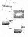
Figure 1c shows a prior design having an externalcleat bar chamber 9 that extends from atank 11, which contains the windings. The cleat bar chamber increases the width of the transformer. - The overall size of a UHVDC or UHVAC transformer, and in particular the width, is an important consideration in terms ensuring the transformer can be transported easily. It is convenient if the assembled transformer can fit within standard size international shipping containers, for example. To achieve the maximum ratings, it is common for the coils of the transformer to approach the width of a shipping container. Therefore, it is advantageous if the interconnections between the coils do not greatly or do not at all increase the width of the transformer.
- According to a first invention of the invention, we provide a method of assembling a transformer/reactor comprising the steps of;
- receiving a first coil having a first coil end conductor;
- receiving a second coil having a second coil end conductor;
- mounting the first coil and second coil on respective limbs of a magnetic core;
- arranging the first coil such that the first conductor projects outwardly from the first coil from a point between the first and second coils;
- arranging the second coil such that the second conductor projects outwardly from the second coil from a point between the first and second coils; and
- connecting the conductors to form an interconnection between the coils.
- This is advantageous as the ends of the windings of the first and second coil can be arranged such that they can be connected together easily while remaining with a bounding box that surrounds the first and second coils. With the first coil and second coil mounted side by side, the first coil end conductor can be connected to the second coil end conductor within the width of the coils, which is advantageous.
- The first and second conductors may project from the coils at first and second projection points respectively, wherein the first coil end projection point and second coil end projection point are spaced inwardly of a plane that lies along an axial side of the first and second coils.
- The method may include the step of arranging the interconnection such that it extends outwardly from the projection points towards the plane. The interconnection may be arranged to extend substantially wholly within a gap between the coils. The method may include the step of forming an arcuate interconnection or an interconnection that includes a bend therein. This is advantageous as the interconnection is formed within the width of the coils and may not extend past the plane. The fact that it extends outwardly from the projection points and bends or arcs allows the connection between the conductors to be made easily.
- The first coil end conductor and second coil end conductor may be arranged to project outwardly in a substantially radial direction from the first coil and second coil respectively.
- The method may include the steps of;
- mounting a first conducting tube around the first coil end conductor; and
- prior to mounting the second coil in its final position on its limb of the magnetic core in which the coil end conductors are aligned, mounting a second conducting tube around the second coil end conductor.
- The method may further include the steps of;
- mounting two or more insulation rings within one another over the conducting tubes within a snout of the respective coil.
- This is advantageous as the insulation rings can be mounted on the first and second conducting tubes for moving to their final position once the conductors and conducting tubes are connected together and the insulation is built up around the assembly.
- Preferably, the method includes the step of moving the second coil to its final position in which the coil end conductors are aligned, the first and second conducting tubes configured and arranged to provide an access gap therebetween to provide access to the coil end conductors.
- This is advantageous as the conductors and conducting tubes are configured and arranged to allow the coil end conductors to project from the ends of the conducting tubes. Thus, the coil end conductors can be connected together, and insulated, in the gap between the first and second conducting tubes.
- The method may include the step of bridging the gap between the first conducting tube and the second conducting tube with a bridging tube.
- Preferably, the first and second conducting tubes are insulated prior to mounting on the first and second coils. Preferably the first and second conducting tubes are arcuate to compliment the interconnection. Alternatively or in addition, the bend of the interconnection may be provided by the bridging tube.
- Each coil may be insulated and include a snout at the coil end projection point.
- The method may include the step of applying insulation around the first and second conducting tubes and the bridging tube.
- The method may include the step of sliding the insulation rings from the respective snouts over the first and second conducting and bridging tube and applying further insulation over the insulation rings. This is advantageous as the insulation rings provide a pre-installed means to space the layers of insulation.
- Preferably the step of applying insulation includes mounting pre-moulded insulation pieces around the first and second conducting and bridging tube and securing the pieces together. The pre-moulded insulation pieces may be arcuate or include a bend.
- According to a further aspect of the invention, we provide a kit of parts for use in assembling a transformer/reactor, as defined in the first aspect of the invention.
- According to a further aspect of the invention, we provide a transformer/reactor comprising a first coil and second coil mounted on respective limbs of a magnetic core, the coil end conductor of the first coil and coil end conductor of the second coil connected together by an interconnection, wherein the first coil conductor extends from the first coil at a point between the first and second coil and the second first coil conductor extends from the second coil at a point between the first and second coil.
- There now follows, by way of example only, a detailed description of the invention with reference to the accompanying drawings in which;
-
Figure 1a shows an assembled transformer/reactor assembled using an exemplary embodiment of the method of the invention; -
Figure 1b shows a simplified plan view of the assembled transformer/reactor offigure 1 ; -
Figure 1c shows a known transformer having an external cleat bar chamber; -
Figures 2-31 show an example of the steps performed in assembling the transformer/reactor and, in particular, forming a connection between two coils; and -
Figure 32 shows a flow chart illustrating an embodiment of the method of the invention - The size of the transformer is related to its power rating and therefore higher rated transformers tend to be larger in size. The transportation of higher rated transformers is a problem as it is difficult for them to fit inside standard size shipping containers. It is the width of the transformer that is most constrained by this requirement. Multi-limb transformers, in which windings of the transformer are distributed over several limbs of a magnetic core allow the width of the transformer to be reduced but the interconnections between the windings on each limb also need to be compact if the transformer is to fit within a shipping container.
-
Figure 1 shows a transformer/reactor 1 with windings split into two coils,first coil 2 and second coil 3, for distribution over two limbs (obscured by the coils) of amagnetic core 4. - A limb comprises a projection from the
core 4 that extend through the centre of thecoil 2, 3. The end of the windings on the first coil 3 are connected to the end of the windings on thesecond coil 4 and then insulated to form aninterconnection 5. Asecond interconnection 6 is shown inFigure 1 . The coil interconnections are formed between sides of the substantially cylindrical coils rather than between ends. - The
coil interconnection 5 projects from thefirst coil 2 at a first coilend projection point 7 and from the second coil 3 at a second coilend projection point 8. Thecoil interconnection 5 is arcuate in this embodiment, although it could include one or more bends such that it can extend outwardly from one coil and back inwardly to the meet the other coil. The interconnection extends in a direction outwardly from between the coils. The interconnection, while extending outwardly, may not extend beyond the gap between the coils, i.e. beyond the width of the coils. -
Figure 1b shows a simplified plan view of the transformer/reactor 1 shown inFigure 1 . Dashedline 10 represents a plane that lies along the sides of the first andsecond coils 2, 3. The plane would define a side of an imaginary bounding box (shown in dashed lines) that surrounds the first andsecond coils 2, 3. The first coilend projection point 7 and second coilend projection point 8 are spaced inwardly from theplane 10 and the arcuate interconnection extends towards the plane but, in this embodiment, does not extend through it. This is advantageous as theinterconnection 5 lies within the width of thecoils 2, 3 themselves and therefore ensures the interconnection does not increase the overall width of the transformer/reactor 1, which could stop the transformer/reactor 1 being transported in a standard size shipping container, such as a railway shipping container. However, the outwardly extending interconnection provides the space for access to the windings to form an electrical connection between the coils and to subsequently insulate the interconnection as will be discussed below. -
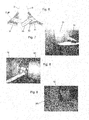
Figures 2 to 31 show an example of the steps to assemble thecoils 2, 3 onto thecore 4 and form theinterconnection 5. -
Figure 2 shows astrand 20 of a first coil end conductor of thefirst coil 2.Several strands 20 may form the first coil end conductor. Aconnector crimp 21 is added to the end of eachstrand 20. Theconnector crimp 21 is crimped around the strand to secure it thereto. Theconnector crimp 21 includes ahole 22 for receiving a bolt, which is used to connect the crimp to a crimp on the second coil end conductor. Thestrands 20 are insulated up to theconnector crimp 21. Apotential lead 23 is connected to one of the strands for connected to a conducting tube discussed below. -
Figure 3 shows thefirst coil 2 mounted on its respective limb and the mounting of afirst conducting tube 32 over the firstcoil end conductor 30. In particular, thefirst coil 2 has been insulated and an aperture has been formed in the insulation to allow the first coil end conductor 30 (formed of several strands having connector crimps connected thereto) to project out of the insulation. Asnout 31 is formed around the aperture comprising a support structure and layers of insulation. Thefirst conducting tube 32 is placed over the firstcoil end conductor 30 and engaged with thesnout 31. Thefirst conducting tube 32 is sized to allow the firstcoil end conductor 30 to project from its free end. Further, thefirst conducting tube 32 is arcuate and its external surface is partially insulated. -
Figure 3 also shows the mounting of several insulation tubes 33 (also known as concentric barriers) that slot inside one another over thefirst conducting tube 32. Theinsulation tubes 33 are mounted within thesnout 31 and provide a spacing and supporting function for further parts of the insulation assembly as well as acting as part of the insulation assembly themselves. Theinsulation tubes 33 are typically approximately 150mm long, although it will be appreciated that other sizes are possible. -
Figures 4 and 5 show thesecond coil 4 mounted on its respective limb but not resting in its final position. The second coil is spaced from its final position such that the firstcoil end conductor 30 is not aligned end-to-end with the secondcoil end conductor 40. However, theconductors coils 2, 3. This allows the length of the secondcoil end conductor 40 to be adjusted so that when the second coil 3 is lowered to its final position, theconductors coil end conductor 40 are cut to length and connector crimps 41 added to each strand (as shown inFigure 4 ). The strands that make up the secondcoil end conductor 40 are insulated up to the connector crimps 41. Stress shields comprising shaped electrodes are positioned at the ends of the windings to improve the electrical stress. The stress shields are connected to the winding end by the potential leads 23. - The
second conducting tube 60 is inserted into asnout 61 on the second coil 3 while it is in its spaced position. Also,several insulation tubes 62 that slot inside one another are mounted over thesecond conducting tube 60. Theinsulation tubes 62 are mounted within thesnout 61 and provide a spacing and supporting function for further parts of the insulation assembly as well as acting as part of the insulation assembly themselves. Thesecond coil 4 is then moved to its final position in which the first and secondcoil end conductors -
Figure 6 illustrates why thesecond conducting tube 60 is installed over the secondcoil end conductor 40 while thesecond coil 4 is spaced from alignment with the first coil 3 in an axial direction. As can be seen, thesecond conducting tube 60 can not be slotted into thesnout 61 when the first and second coils are in the final position shown inFigure 6 . -
Figure 7 shows a loop ofcotton tape 70 fitted around one of theinsulation tubes snouts tape 70 must be removed. -
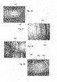
Figure 8 shows the firstcoil end conductor 20 and secondcoil end conductor 40 being connected together by bolts that extend through theholes 22 in thecrimp connectors Figure 2 , is connected to aconnector 90 on one of the first andsecond conducting tubes Figure 9 shows theconnector 90 which, in this embodiment, extends from the inside surface of thefirst conducting tube 32. -
Figure 10 shows the bridging of the gap between the first andsecond conducting tubes bridging tube 100. The bridgingtube 100 comprises twohalves Figure 8 that the ends of the first andsecond conducting tubes tube 100 can make an electrical connection with thetubes Screws 101 are used to secure the bridgingtube 100 to thetubes tube 100. -
Figure 11 shows the first andsecond conducting tubes tube 100 wrapped with insulation comprisingcrepe paper 1100, for example, between thesnouts -
Figure 12 shows apressboard barrier 1200 applied at opposed ends of the crepe paper insulation 1100 (only one end visible inFigure 12 ). Thepressboard barrier 1200 is of 0.8 mm thick by 50 mm wide pressboard and is arranged to overlap with thepaper insulation 1100 by approximately 25 mm. -
Figure 13 shows twobands interconnection 5. The bands are approximately 1 mm thick and are each spaced from theinsulation 1100 by three pairs of pressboard strips 1302-1307. The pressboards strips are placed in the top (1302 and 1305), front (1303 and 1306) and bottom (1304, 1307) of the interconnection. This is because thepaper tape 1100 applied in the previous step will have a greater thickness at the back as this is the inside of the bend of the arcuate interconnection. Thebands paper tape 1100 and the further insulation. -
Figure 14 shows the further insulation applied in the form of anangled barrier 1400. The angled barrier is pre-moulded in two halves and sits on thebands bands angled barrier 1400, in this embodiment, is of moulded pressboard and it forms part of the concentric insulation structure around the interconnection. -
Figure 15 shows application of corrugated pressboard rings 1500 at each end of theinterconnection 5.Figures 15 to 17 show the positioning ofinsulation tubes tubes Figure 15 shows a concentric barrier that is placed over (and therefore obscures) a corrugated pressboard ring corresponding tocorrugated pressboard ring 1500. The concentric barrier shown inFigure 15 comprises the secondconcentric barrier 1501 as it is on the side of thesecond coil 4. The secondconcentric barrier 1501 is slid out from thesnout 61. Thebarrier 1501 is secured in place with paper tape around the barrier. It is also secured with tape that extends around thebarrier 1501 and onto theangled barrier 1400. - The girth of the second
concentric barrier 1501 is required to be within a predetermined range. The pressboard rings 1500 can be reduced in thickness or built up with tape to ensure thebarrier 1501 has the correct girth. -
Figure 17 shows the firstconcentric barrier 1701 moved into position and secured just like thesecond barrier 1501 described above. -
Figure 18 shows the formation of oil flow holes 1800 through the tape applied in the previous figures that bridges the firstconcentric barrier 1701 and theangled barrier 1400. Oil flow holes 1800 are also applied through the tape that bridges the secondconcentric barrier 1501 and theangled barrier 1400. The oil flow holes 1800 may be approximately 10 mm in diameter and equally spaced around eachconcentric barrier -
Figures 19 and 20 show the installation of a secondangled barrier 1900. The secondangled barrier 1900 is pre-moulded in two halves (one half shown inFigure 19 ) and sits on theconcentric barriers bands 2001, 2002 of paper tape. -
Figures 21 and22 show a condensed version of the installation process shown inFigures 15 to 17 . Infigure 17 corrugated pressboard rings are applied at each end of theinterconnection 5. A second pair ofconcentric barriers angled barrier 2200 is fitted over the second pair ofconcentric barriers -
Figure 23 shows the installation of a third set of concentric barriers with associated pressboard rings and a fourthangled barrier 2300. A fourth set ofconcentric barriers 2310 and a fifth set ofconcentric barriers 2320 are positioned and secured without an angled barrier therebetween. -
Figure 24 shows the installation of a fifthangled barrier 2400 that is mounted over the fifth set of concentric barriers. The fifthangled barrier 2400 is secured with two bands of paper tape. -
Figure 25 shows theinterconnection 5 almost built up to the thickness of thesnouts -
Figure 26 and figure 27 shows the installation of a sixth set ofconcentric barriers 2600 with the associated pressboard rings 2601.Figure 27 shows a detailed view ofFigure 26 . -
Figure 28 shows the addition of a sixthangled barrier 2800 that is mounted onto the sixth set ofconcentric barriers 2600 and secured in place by bands of tape. -
Figure 29 shows the installation of a seventh set ofconcentric barriers 2900 with the associated pressboard rings (hidden from view). The seventh set ofconcentric barriers 2900 comprise afirst barrier 2901 and asecond barrier 2902. The first andsecond barriers first barrier 2901 extends between theinterconnection 5 and thesnout 31. Thesecond barrier 2902 extends between theinterconnection 5 and thesnout 61. - As shown in
Figures 30 and 31 , the first andsecond barriers webbing angled barrier 2800 is also secured withwebbing 3101. The webbing is sewn to prevent it coming undone. - The completed
interconnection 5 is shown inFigure 31 . -
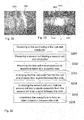
Figure 32 shows a flow chart illustrating the method of the invention.Step 3201 comprises receiving a first coil having a first coil end conductor.Step 3202 comprises receiving a second coil having a second coil end conductor.Step 3203 comprises mounting the first coil and second coil on respective limbs of a magnetic core.Step 3204 shows arranging the first coil such that the first coil end projects from a point between the coils.Step 3205 shows arranging the second coil such that the second coil end projects outwardly from the second coil from a point between the coils.Step 3206 shows connecting the conductors to form an interconnection between the coils. The first coil end projection point and second coil end projection point can be spaced inwardly of a plane that lies along an axial side of the first and second coils and the interconnection can be arranged to extend outwardly from the projection points while remaining within the gap between the first and second coil. - It will be appreciated that while the
interconnection 5 is shown as being arcuate between the projection points 7, 8 it may extend outwardly and have a bend therein. Alternatively, the interconnection may be substantially straight.
Claims (16)
- A method of assembling a transformer/reactor comprising the steps of;
receiving a first coil (2) having a first coil end conductor (30);
receiving a second coil (3) having a second coil end conductor (40);
mounting the first coil and second coil on respective limbs of a magnetic core (4);
arranging the first coil such that the first conductor projects outwardly from the first coil from a point (7) between the first and second coils;
arranging the second coil such that the second conductor projects outwardly from the second coil from a point (8) between the first and second coils; and
connecting the conductors to form an interconnection (5) between the coils. - A method according to claim 1, in which the first and second conductors project from the coils at first and second projection points (7, 8) respectively, wherein the first coil end projection point and second coil end projection point are spaced inwardly of a plane (10) that lies along an axial side of the first and second coils (2, 3).
- A method according to claim 2, in which the method includes the step of arranging the interconnection such that it extends outwardly from the projection points towards the plane.
- A method according to claim 3, in which the interconnection is arranged to extend substantially wholly within a gap between the coils.
- A method according to any preceding claim, in which the method includes the step of forming an arcuate interconnection or an interconnection that includes a bend therein.
- A method according to any preceding claim, in which the first coil end conductor (30) and second coil end conductor (40) are arranged to project outwardly in a substantially radial direction from the first coil and second coil respectively.
- A method according to any preceding claim, in which the method include the steps of;
mounting a first conducting tube (32) around the first coil end conductor; and
prior to mounting the second coil in its final position on its limb of the magnetic core, in which the coil end conductors are aligned, mounting a second conducting tube (60) around the second coil end conductor. - A method according to claim 7, in which the method further includes the steps of;
mounting two or more insulation rings over the conducting tubes within a snout (31, 61) of the respective coil. - A method according to claim 7 or claim 8, in which the method includes the step of moving the second coil to its final position in which the coil end conductors are aligned, the first and second conducting tubes configured to have a gap therebetween to provide access to the coil end conductors.
- A method according to any one of claims 7 to 9, in which the method includes the step of bridging the gap between the first conducting tube (32) and the second conducting tube (60) with a bridging tube (100).
- A method according to claim 10, in which the method includes the step of applying insulation around the first and second conducting tubes and bridging tube.
- A method according to claim 8 in which the method includes the step of sliding the insulation spacer rings from the respective snouts over the first and second conducting tubes and bridging tube and applying further insulation over the insulation rings.
- A method according to claim 11, in which the step of applying insulation includes mounting pre-moulded insulation pieces around the first and second conducting tubes and bridging tube and securing the pieces together.
- A method according to claim 12, in which the insulation spacer rings are used to space apart layers of the pre-moulded insulation pieces.
- A kit of parts for use in assembling a transformer/reactor, as defined in any one of claims 1 to 14.
- A transformer/reactor comprising a first coil (2) and second coil (3) mounted on respective limbs of a magnetic core (4), the coil end conductor (30) of the first coil (3) and coil end conductor (40) of the second coil (4) connected together by an interconnection (5), wherein the first coil conductor extends from the first coil at a point between the first and second coil and the second first coil conductor extends from the second coil at a point between the first and second coil.
Priority Applications (7)
| Application Number | Priority Date | Filing Date | Title |
|---|---|---|---|
| EP13173642.3A EP2819132B1 (en) | 2013-06-25 | 2013-06-25 | Method of assembling a transformer |
| PCT/EP2014/063308 WO2014206994A1 (en) | 2013-06-25 | 2014-06-24 | Method of assembling a transformer |
| BR102014015636-4A BR102014015636B1 (en) | 2013-06-25 | 2014-06-24 | method of assembling a transformer / reactor, kit of parts for use in assembling a transformer / reactor and transformer / reactor |
| US14/900,086 US10256040B2 (en) | 2013-06-25 | 2014-06-24 | Method of assembling a transformer |
| IN2027MU2014 IN2014MU02027A (en) | 2013-06-25 | 2014-06-24 | |
| CN201410289677.1A CN104252962B (en) | 2013-06-25 | 2014-06-25 | The method of assembling transformer |
| KR1020140078025A KR102159689B1 (en) | 2013-06-25 | 2014-06-25 | Method of assembling a transformer |
Applications Claiming Priority (1)
| Application Number | Priority Date | Filing Date | Title |
|---|---|---|---|
| EP13173642.3A EP2819132B1 (en) | 2013-06-25 | 2013-06-25 | Method of assembling a transformer |
Publications (2)
| Publication Number | Publication Date |
|---|---|
| EP2819132A1 true EP2819132A1 (en) | 2014-12-31 |
| EP2819132B1 EP2819132B1 (en) | 2016-02-10 |
Family
ID=48670446
Family Applications (1)
| Application Number | Title | Priority Date | Filing Date |
|---|---|---|---|
| EP13173642.3A Active EP2819132B1 (en) | 2013-06-25 | 2013-06-25 | Method of assembling a transformer |
Country Status (7)
| Country | Link |
|---|---|
| US (1) | US10256040B2 (en) |
| EP (1) | EP2819132B1 (en) |
| KR (1) | KR102159689B1 (en) |
| CN (1) | CN104252962B (en) |
| BR (1) | BR102014015636B1 (en) |
| IN (1) | IN2014MU02027A (en) |
| WO (1) | WO2014206994A1 (en) |
Cited By (1)
| Publication number | Priority date | Publication date | Assignee | Title |
|---|---|---|---|---|
| EP3076409A1 (en) * | 2015-03-30 | 2016-10-05 | Siemens Aktiengesellschaft | Electrical connection between separated windings |
Families Citing this family (2)
| Publication number | Priority date | Publication date | Assignee | Title |
|---|---|---|---|---|
| CN105957705A (en) * | 2016-06-03 | 2016-09-21 | 成都市蒂娜亚文化传媒有限公司 | Efficient transformer device with guiding and positioning device and application method of efficient transformer device |
| EP3273451B1 (en) * | 2016-07-22 | 2019-11-27 | General Electric Technology GmbH | A lead exit arrangement |
Citations (2)
| Publication number | Priority date | Publication date | Assignee | Title |
|---|---|---|---|---|
| US1554664A (en) * | 1925-03-19 | 1925-09-22 | Gen Electric | Transformer |
| US3774135A (en) * | 1972-12-21 | 1973-11-20 | Hitachi Ltd | Stationary induction apparatus |
Family Cites Families (5)
| Publication number | Priority date | Publication date | Assignee | Title |
|---|---|---|---|---|
| JPH08138785A (en) * | 1994-11-10 | 1996-05-31 | Yazaki Corp | Connector equipped with shutter mechanism |
| CN201178017Y (en) | 2007-12-28 | 2009-01-07 | 保定天威集团有限公司 | Balance tube for transformer connecting between pillars |
| CN201667276U (en) | 2010-02-24 | 2010-12-08 | 中国西电电气股份有限公司 | Intercolumnar wiring device for ultrahigh-voltage transformer |
| DE102011008456A1 (en) * | 2011-01-07 | 2012-07-12 | Siemens Aktiengesellschaft | Cable routing for HVDC transformer coils or HVDC choke coils |
| CN102592793B (en) | 2011-01-10 | 2014-11-12 | 特变电工衡阳变压器有限公司 | Wire connection structure between high-voltage windings of ultra-high voltage transformer |
-
2013
- 2013-06-25 EP EP13173642.3A patent/EP2819132B1/en active Active
-
2014
- 2014-06-24 IN IN2027MU2014 patent/IN2014MU02027A/en unknown
- 2014-06-24 BR BR102014015636-4A patent/BR102014015636B1/en active IP Right Grant
- 2014-06-24 WO PCT/EP2014/063308 patent/WO2014206994A1/en active Application Filing
- 2014-06-24 US US14/900,086 patent/US10256040B2/en active Active
- 2014-06-25 KR KR1020140078025A patent/KR102159689B1/en active IP Right Grant
- 2014-06-25 CN CN201410289677.1A patent/CN104252962B/en active Active
Patent Citations (2)
| Publication number | Priority date | Publication date | Assignee | Title |
|---|---|---|---|---|
| US1554664A (en) * | 1925-03-19 | 1925-09-22 | Gen Electric | Transformer |
| US3774135A (en) * | 1972-12-21 | 1973-11-20 | Hitachi Ltd | Stationary induction apparatus |
Cited By (1)
| Publication number | Priority date | Publication date | Assignee | Title |
|---|---|---|---|---|
| EP3076409A1 (en) * | 2015-03-30 | 2016-10-05 | Siemens Aktiengesellschaft | Electrical connection between separated windings |
Also Published As
| Publication number | Publication date |
|---|---|
| KR102159689B1 (en) | 2020-09-25 |
| KR20150000845A (en) | 2015-01-05 |
| IN2014MU02027A (en) | 2015-10-02 |
| CN104252962B (en) | 2019-04-30 |
| BR102014015636A2 (en) | 2015-11-24 |
| US20160148754A1 (en) | 2016-05-26 |
| US10256040B2 (en) | 2019-04-09 |
| EP2819132B1 (en) | 2016-02-10 |
| BR102014015636B1 (en) | 2021-03-02 |
| CN104252962A (en) | 2014-12-31 |
| WO2014206994A1 (en) | 2014-12-31 |
Similar Documents
| Publication | Publication Date | Title |
|---|---|---|
| DE102016209883B4 (en) | wiring harness | |
| US9202621B2 (en) | Slotted bobbin magnetic component devices and methods | |
| CN100580459C (en) | Current measurement apparatus | |
| JP6149800B2 (en) | Shield conductive path | |
| US7859380B2 (en) | Bobbin assembly | |
| US10256040B2 (en) | Method of assembling a transformer | |
| CN103930958A (en) | Wind-on core manufacturing method for split core configurations | |
| CN105099018A (en) | Motor insulating framework and motor having the framework | |
| US9978503B2 (en) | Transformer winding, transformer having the same and manufacturing method thereof | |
| CN107077953B (en) | Coil arragement construction and transformer with low interwinding capacity | |
| DK2490229T3 (en) | Transformer, amorphous transformer and method of manufacturing the transformer | |
| US20140209345A1 (en) | Power Connector for an Electrical Motor | |
| US7741945B2 (en) | Dry-type transformer with improved terminal construction and mounting system therefor | |
| US11688552B2 (en) | Method for assembling a magnetic inductor and magnetic inductor able to be obtained by means of such a method | |
| CN106165034A (en) | Suppressor choke coil | |
| US20110266912A1 (en) | Rotating electric machine with a stator winding comprising a plurality of coils and method for manufacturing same | |
| US20130076471A1 (en) | Transformer and assembling method thereof | |
| JP6466728B2 (en) | Transformer and manufacturing method thereof | |
| DE202021004303U1 (en) | inductor assemblies | |
| CN216819549U (en) | Motor wiring structure and motor | |
| CN217036883U (en) | Motor wiring structure and motor | |
| EP3622545A1 (en) | High voltage high frequency transformer | |
| EP3159904A1 (en) | Dry type cast transformer with flexible connection terminal | |
| CA1155941A (en) | Corona-free insulating support structure with self-locking means | |
| CN104143417B (en) | A kind of transformator |
Legal Events
| Date | Code | Title | Description |
|---|---|---|---|
| PUAI | Public reference made under article 153(3) epc to a published international application that has entered the european phase |
Free format text: ORIGINAL CODE: 0009012 |
|
| 17P | Request for examination filed |
Effective date: 20140530 |
|
| AK | Designated contracting states |
Kind code of ref document: A1 Designated state(s): AL AT BE BG CH CY CZ DE DK EE ES FI FR GB GR HR HU IE IS IT LI LT LU LV MC MK MT NL NO PL PT RO RS SE SI SK SM TR |
|
| AX | Request for extension of the european patent |
Extension state: BA ME |
|
| GRAP | Despatch of communication of intention to grant a patent |
Free format text: ORIGINAL CODE: EPIDOSNIGR1 |
|
| INTG | Intention to grant announced |
Effective date: 20150223 |
|
| RIN1 | Information on inventor provided before grant (corrected) |
Inventor name: WRIGHT, DAVID WALTER |
|
| GRAP | Despatch of communication of intention to grant a patent |
Free format text: ORIGINAL CODE: EPIDOSNIGR1 |
|
| INTG | Intention to grant announced |
Effective date: 20150803 |
|
| GRAS | Grant fee paid |
Free format text: ORIGINAL CODE: EPIDOSNIGR3 |
|
| RAP1 | Party data changed (applicant data changed or rights of an application transferred) |
Owner name: GENERAL ELECTRIC TECHNOLOGY GMBH |
|
| GRAA | (expected) grant |
Free format text: ORIGINAL CODE: 0009210 |
|
| INTG | Intention to grant announced |
Effective date: 20151209 |
|
| AK | Designated contracting states |
Kind code of ref document: B1 Designated state(s): AL AT BE BG CH CY CZ DE DK EE ES FI FR GB GR HR HU IE IS IT LI LT LU LV MC MK MT NL NO PL PT RO RS SE SI SK SM TR |
|
| REG | Reference to a national code |
Ref country code: GB Ref legal event code: FG4D |
|
| REG | Reference to a national code |
Ref country code: AT Ref legal event code: REF Ref document number: 775009 Country of ref document: AT Kind code of ref document: T Effective date: 20160215 Ref country code: CH Ref legal event code: EP |
|
| REG | Reference to a national code |
Ref country code: IE Ref legal event code: FG4D |
|
| REG | Reference to a national code |
Ref country code: DE Ref legal event code: R096 Ref document number: 602013004991 Country of ref document: DE |
|
| REG | Reference to a national code |
Ref country code: SE Ref legal event code: TRGR |
|
| REG | Reference to a national code |
Ref country code: LT Ref legal event code: MG4D |
|
| REG | Reference to a national code |
Ref country code: NL Ref legal event code: MP Effective date: 20160210 |
|
| REG | Reference to a national code |
Ref country code: FR Ref legal event code: PLFP Year of fee payment: 4 |
|
| REG | Reference to a national code |
Ref country code: AT Ref legal event code: MK05 Ref document number: 775009 Country of ref document: AT Kind code of ref document: T Effective date: 20160210 |
|
| PG25 | Lapsed in a contracting state [announced via postgrant information from national office to epo] |
Ref country code: NO Free format text: LAPSE BECAUSE OF FAILURE TO SUBMIT A TRANSLATION OF THE DESCRIPTION OR TO PAY THE FEE WITHIN THE PRESCRIBED TIME-LIMIT Effective date: 20160510 Ref country code: IT Free format text: LAPSE BECAUSE OF FAILURE TO SUBMIT A TRANSLATION OF THE DESCRIPTION OR TO PAY THE FEE WITHIN THE PRESCRIBED TIME-LIMIT Effective date: 20160210 Ref country code: FI Free format text: LAPSE BECAUSE OF FAILURE TO SUBMIT A TRANSLATION OF THE DESCRIPTION OR TO PAY THE FEE WITHIN THE PRESCRIBED TIME-LIMIT Effective date: 20160210 Ref country code: ES Free format text: LAPSE BECAUSE OF FAILURE TO SUBMIT A TRANSLATION OF THE DESCRIPTION OR TO PAY THE FEE WITHIN THE PRESCRIBED TIME-LIMIT Effective date: 20160210 Ref country code: HR Free format text: LAPSE BECAUSE OF FAILURE TO SUBMIT A TRANSLATION OF THE DESCRIPTION OR TO PAY THE FEE WITHIN THE PRESCRIBED TIME-LIMIT Effective date: 20160210 Ref country code: GR Free format text: LAPSE BECAUSE OF FAILURE TO SUBMIT A TRANSLATION OF THE DESCRIPTION OR TO PAY THE FEE WITHIN THE PRESCRIBED TIME-LIMIT Effective date: 20160511 |
|
| PG25 | Lapsed in a contracting state [announced via postgrant information from national office to epo] |
Ref country code: PT Free format text: LAPSE BECAUSE OF FAILURE TO SUBMIT A TRANSLATION OF THE DESCRIPTION OR TO PAY THE FEE WITHIN THE PRESCRIBED TIME-LIMIT Effective date: 20160613 Ref country code: RS Free format text: LAPSE BECAUSE OF FAILURE TO SUBMIT A TRANSLATION OF THE DESCRIPTION OR TO PAY THE FEE WITHIN THE PRESCRIBED TIME-LIMIT Effective date: 20160210 Ref country code: IS Free format text: LAPSE BECAUSE OF FAILURE TO SUBMIT A TRANSLATION OF THE DESCRIPTION OR TO PAY THE FEE WITHIN THE PRESCRIBED TIME-LIMIT Effective date: 20160610 Ref country code: PL Free format text: LAPSE BECAUSE OF FAILURE TO SUBMIT A TRANSLATION OF THE DESCRIPTION OR TO PAY THE FEE WITHIN THE PRESCRIBED TIME-LIMIT Effective date: 20160210 Ref country code: NL Free format text: LAPSE BECAUSE OF FAILURE TO SUBMIT A TRANSLATION OF THE DESCRIPTION OR TO PAY THE FEE WITHIN THE PRESCRIBED TIME-LIMIT Effective date: 20160210 Ref country code: LT Free format text: LAPSE BECAUSE OF FAILURE TO SUBMIT A TRANSLATION OF THE DESCRIPTION OR TO PAY THE FEE WITHIN THE PRESCRIBED TIME-LIMIT Effective date: 20160210 Ref country code: AT Free format text: LAPSE BECAUSE OF FAILURE TO SUBMIT A TRANSLATION OF THE DESCRIPTION OR TO PAY THE FEE WITHIN THE PRESCRIBED TIME-LIMIT Effective date: 20160210 Ref country code: LV Free format text: LAPSE BECAUSE OF FAILURE TO SUBMIT A TRANSLATION OF THE DESCRIPTION OR TO PAY THE FEE WITHIN THE PRESCRIBED TIME-LIMIT Effective date: 20160210 |
|
| PG25 | Lapsed in a contracting state [announced via postgrant information from national office to epo] |
Ref country code: EE Free format text: LAPSE BECAUSE OF FAILURE TO SUBMIT A TRANSLATION OF THE DESCRIPTION OR TO PAY THE FEE WITHIN THE PRESCRIBED TIME-LIMIT Effective date: 20160210 Ref country code: DK Free format text: LAPSE BECAUSE OF FAILURE TO SUBMIT A TRANSLATION OF THE DESCRIPTION OR TO PAY THE FEE WITHIN THE PRESCRIBED TIME-LIMIT Effective date: 20160210 |
|
| REG | Reference to a national code |
Ref country code: DE Ref legal event code: R097 Ref document number: 602013004991 Country of ref document: DE |
|
| PG25 | Lapsed in a contracting state [announced via postgrant information from national office to epo] |
Ref country code: SK Free format text: LAPSE BECAUSE OF FAILURE TO SUBMIT A TRANSLATION OF THE DESCRIPTION OR TO PAY THE FEE WITHIN THE PRESCRIBED TIME-LIMIT Effective date: 20160210 Ref country code: RO Free format text: LAPSE BECAUSE OF FAILURE TO SUBMIT A TRANSLATION OF THE DESCRIPTION OR TO PAY THE FEE WITHIN THE PRESCRIBED TIME-LIMIT Effective date: 20160210 Ref country code: CZ Free format text: LAPSE BECAUSE OF FAILURE TO SUBMIT A TRANSLATION OF THE DESCRIPTION OR TO PAY THE FEE WITHIN THE PRESCRIBED TIME-LIMIT Effective date: 20160210 Ref country code: SM Free format text: LAPSE BECAUSE OF FAILURE TO SUBMIT A TRANSLATION OF THE DESCRIPTION OR TO PAY THE FEE WITHIN THE PRESCRIBED TIME-LIMIT Effective date: 20160210 |
|
| PLBE | No opposition filed within time limit |
Free format text: ORIGINAL CODE: 0009261 |
|
| STAA | Information on the status of an ep patent application or granted ep patent |
Free format text: STATUS: NO OPPOSITION FILED WITHIN TIME LIMIT |
|
| PG25 | Lapsed in a contracting state [announced via postgrant information from national office to epo] |
Ref country code: BE Free format text: LAPSE BECAUSE OF FAILURE TO SUBMIT A TRANSLATION OF THE DESCRIPTION OR TO PAY THE FEE WITHIN THE PRESCRIBED TIME-LIMIT Effective date: 20160210 |
|
| 26N | No opposition filed |
Effective date: 20161111 |
|
| PG25 | Lapsed in a contracting state [announced via postgrant information from national office to epo] |
Ref country code: MC Free format text: LAPSE BECAUSE OF FAILURE TO SUBMIT A TRANSLATION OF THE DESCRIPTION OR TO PAY THE FEE WITHIN THE PRESCRIBED TIME-LIMIT Effective date: 20160210 |
|
| REG | Reference to a national code |
Ref country code: CH Ref legal event code: PL |
|
| PG25 | Lapsed in a contracting state [announced via postgrant information from national office to epo] |
Ref country code: BG Free format text: LAPSE BECAUSE OF FAILURE TO SUBMIT A TRANSLATION OF THE DESCRIPTION OR TO PAY THE FEE WITHIN THE PRESCRIBED TIME-LIMIT Effective date: 20160510 Ref country code: SI Free format text: LAPSE BECAUSE OF FAILURE TO SUBMIT A TRANSLATION OF THE DESCRIPTION OR TO PAY THE FEE WITHIN THE PRESCRIBED TIME-LIMIT Effective date: 20160210 |
|
| REG | Reference to a national code |
Ref country code: IE Ref legal event code: MM4A |
|
| PG25 | Lapsed in a contracting state [announced via postgrant information from national office to epo] |
Ref country code: LI Free format text: LAPSE BECAUSE OF NON-PAYMENT OF DUE FEES Effective date: 20160630 Ref country code: CH Free format text: LAPSE BECAUSE OF NON-PAYMENT OF DUE FEES Effective date: 20160630 |
|
| PG25 | Lapsed in a contracting state [announced via postgrant information from national office to epo] |
Ref country code: IE Free format text: LAPSE BECAUSE OF NON-PAYMENT OF DUE FEES Effective date: 20160625 |
|
| REG | Reference to a national code |
Ref country code: FR Ref legal event code: PLFP Year of fee payment: 5 |
|
| PG25 | Lapsed in a contracting state [announced via postgrant information from national office to epo] |
Ref country code: HU Free format text: LAPSE BECAUSE OF FAILURE TO SUBMIT A TRANSLATION OF THE DESCRIPTION OR TO PAY THE FEE WITHIN THE PRESCRIBED TIME-LIMIT; INVALID AB INITIO Effective date: 20130625 |
|
| REG | Reference to a national code |
Ref country code: FR Ref legal event code: PLFP Year of fee payment: 6 |
|
| PG25 | Lapsed in a contracting state [announced via postgrant information from national office to epo] |
Ref country code: CY Free format text: LAPSE BECAUSE OF FAILURE TO SUBMIT A TRANSLATION OF THE DESCRIPTION OR TO PAY THE FEE WITHIN THE PRESCRIBED TIME-LIMIT Effective date: 20160210 Ref country code: LU Free format text: LAPSE BECAUSE OF NON-PAYMENT OF DUE FEES Effective date: 20160625 Ref country code: MK Free format text: LAPSE BECAUSE OF FAILURE TO SUBMIT A TRANSLATION OF THE DESCRIPTION OR TO PAY THE FEE WITHIN THE PRESCRIBED TIME-LIMIT Effective date: 20160210 Ref country code: MT Free format text: LAPSE BECAUSE OF NON-PAYMENT OF DUE FEES Effective date: 20160630 |
|
| PG25 | Lapsed in a contracting state [announced via postgrant information from national office to epo] |
Ref country code: TR Free format text: LAPSE BECAUSE OF FAILURE TO SUBMIT A TRANSLATION OF THE DESCRIPTION OR TO PAY THE FEE WITHIN THE PRESCRIBED TIME-LIMIT Effective date: 20160210 Ref country code: AL Free format text: LAPSE BECAUSE OF FAILURE TO SUBMIT A TRANSLATION OF THE DESCRIPTION OR TO PAY THE FEE WITHIN THE PRESCRIBED TIME-LIMIT Effective date: 20160210 |
|
| P01 | Opt-out of the competence of the unified patent court (upc) registered |
Effective date: 20230522 |
|
| PGFP | Annual fee paid to national office [announced via postgrant information from national office to epo] |
Ref country code: FR Payment date: 20230524 Year of fee payment: 11 Ref country code: DE Payment date: 20230523 Year of fee payment: 11 |
|
| PGFP | Annual fee paid to national office [announced via postgrant information from national office to epo] |
Ref country code: SE Payment date: 20230523 Year of fee payment: 11 |
|
| PGFP | Annual fee paid to national office [announced via postgrant information from national office to epo] |
Ref country code: GB Payment date: 20230523 Year of fee payment: 11 |