EP2818984A1 - Touch panel input device and control method for same - Google Patents
Touch panel input device and control method for same Download PDFInfo
- Publication number
- EP2818984A1 EP2818984A1 EP12869135.9A EP12869135A EP2818984A1 EP 2818984 A1 EP2818984 A1 EP 2818984A1 EP 12869135 A EP12869135 A EP 12869135A EP 2818984 A1 EP2818984 A1 EP 2818984A1
- Authority
- EP
- European Patent Office
- Prior art keywords
- display
- touch panel
- contact
- displayed
- proximity
- Prior art date
- Legal status (The legal status is an assumption and is not a legal conclusion. Google has not performed a legal analysis and makes no representation as to the accuracy of the status listed.)
- Granted
Links
Images





Classifications
-
- G—PHYSICS
- G06—COMPUTING OR CALCULATING; COUNTING
- G06F—ELECTRIC DIGITAL DATA PROCESSING
- G06F3/00—Input arrangements for transferring data to be processed into a form capable of being handled by the computer; Output arrangements for transferring data from processing unit to output unit, e.g. interface arrangements
- G06F3/01—Input arrangements or combined input and output arrangements for interaction between user and computer
- G06F3/048—Interaction techniques based on graphical user interfaces [GUI]
- G06F3/0487—Interaction techniques based on graphical user interfaces [GUI] using specific features provided by the input device, e.g. functions controlled by the rotation of a mouse with dual sensing arrangements, or of the nature of the input device, e.g. tap gestures based on pressure sensed by a digitiser
- G06F3/0488—Interaction techniques based on graphical user interfaces [GUI] using specific features provided by the input device, e.g. functions controlled by the rotation of a mouse with dual sensing arrangements, or of the nature of the input device, e.g. tap gestures based on pressure sensed by a digitiser using a touch-screen or digitiser, e.g. input of commands through traced gestures
- G06F3/04886—Interaction techniques based on graphical user interfaces [GUI] using specific features provided by the input device, e.g. functions controlled by the rotation of a mouse with dual sensing arrangements, or of the nature of the input device, e.g. tap gestures based on pressure sensed by a digitiser using a touch-screen or digitiser, e.g. input of commands through traced gestures by partitioning the display area of the touch-screen or the surface of the digitising tablet into independently controllable areas, e.g. virtual keyboards or menus
-
- G—PHYSICS
- G06—COMPUTING OR CALCULATING; COUNTING
- G06F—ELECTRIC DIGITAL DATA PROCESSING
- G06F3/00—Input arrangements for transferring data to be processed into a form capable of being handled by the computer; Output arrangements for transferring data from processing unit to output unit, e.g. interface arrangements
- G06F3/01—Input arrangements or combined input and output arrangements for interaction between user and computer
- G06F3/03—Arrangements for converting the position or the displacement of a member into a coded form
- G06F3/041—Digitisers, e.g. for touch screens or touch pads, characterised by the transducing means
- G06F3/0412—Digitisers structurally integrated in a display
Definitions
- the present invention relates to a touch panel input device and a control method of the touch panel input device.
- Touch panels are mounted on many devices, such as smartphones, and the touch panels are growing in usage.
- the touch panels are used not only to check messages belonging to consumer or entertainment, but also for mission-critical operations such as there related to finance or life.
- mission-critical operations such as there related to finance or life.
- the user visually recognizes an object (button or selectable area) displayed on a screen and touches the object (or area of the object) with a finger or the like, software recognizes the selection operation and executes an operation associated in advance with the object.
- Patent Literature 1 and 2 Techniques for enlarging and displaying a touched area or displaying a pointer when a contact operation to a touch panel is performed are disclosed in, for example Patent Literature 1 and 2.
- buttons arranged on the wrong screen are functions for deleting of user data or for emergency notification transmission, this may be a crucial operational error for the user. Therefore, touch panel operation on a mission-critical system contains a defect that may potentially cause an operational error on the surface of the user interface.
- Figures 1a to 1d are diagrams for explaining normal operation in a general touch panel input device.
- a touch panel input device having touch panel 120 arranged on display 110 as shown in Figure 1a
- button information 111 in a state in which button information 111 on a pop-up display displayed by certain operation on a normal screen is displayed as shown in Figure 1b
- pointer 121 is displayed on button information 111.
- Figure 1c when finger 102 touches button information 111, an emergency notification transmission operation is performed because button information 111 is an emergency transmission button.
- emergency notification call screen 112 is displayed, and the user's intended operation is performed.
- Figures 2a to 2d are diagrams for explaining the wrong operation in a general touch panel input device.
- button information 111 in a state in which button information 111 on a pop-up display displayed by certain operation on a normal screen is displayed as shown in Figure 2b , pointer 121 is displayed on button information 111.
- some devices have specifications so that when the pop-up display is left unoperated, the pop-up display automatically disappears after a certain time period if the time has expired as a result of using a timer function, and the display on display 110 autonomously switches.
- button information 111 based on the pop-up display may disappear as shown in Figure 2c before finger 102 contacts touch panel 120 after the user visually recognizes the screen. Therefore, although the user intends to perform an emergency transmission, operation of pressing a "5" key of voice call displayed in an area where button information 111 has been displayed in display 110 will be performed as shown in Figure 2d .
- a screen not using a pop-up display can be constructed.
- the pop-up display is a general user interface for current smartphones. The construction without using the pop-up display is difficult, and the usability and the visibility are lost.
- auxiliary information of the object is displayed.
- auxiliary information of an object cannot be displayed before the object on the screen is touched.
- an operation associated with the object is performed at the same time as the contact, and the auxiliary information of the object cannot be displayed.
- the present invention provides a touch panel input device including: a display that displays information; a touch panel that is arranged on the display and that detects proximity and contact operation of a contact body; and a controller that controls the display of the information in the display and that receives input according to the contact operation detected at the touch panel, the controller autonomously switching the display in the display, wherein when the touch panel detects proximity of a contact body, the controller does not switch the display in the display after the detection of the proximity and detection of contact of the contact body with the touch panel, until the contact is no longer detected.
- a touch panel input device including: a display that displays information; a touch panel that is arranged on the display and that detects proximity and contact operation of a contact body; and a controller that controls the display of the information in the display and that receives input according to the contact operation detected at the touch panel, wherein when the touch panel detects proximity of a contact body, the controller displays a guide of operation of a case which an area of the touch panel where the approach is detected is contacted.
- a control method of a touch panel input device including: a display that displays information; a touch panel that is arranged on the display and that detects proximity and contact operation of a contact body; and a controller that controls the display of the information in the display and that receives input according to the contact operation detected at the touch panel, the controller autonomously switching the display in the display, wherein when the touch panel detects proximity of a contact body, the display in the display is not switched after the detection of the proximity and detection of contact of the contact body at the touch panel, until the contact is no longer detected.
- a control method of a touch panel input device including: a display that displays information; a touch panel that is arranged on the display and that detects proximity and contact operation of a contact body; and a controller that controls the display of the information in the display and that receives input according to the contact operation detected at the touch panel, wherein when the touch panel detects proximity of a contact body, a guide of operation of a case which an area of the touch panel where the approach is detected is contacted is displayed.
- the display in the display when the touch panel detects proximity of a contact body, the display in the display does not switch after the detection of the proximity and detection of contact of the contact body by the touch panel, until contact is no longer detected. Therefore, after the user brings the contact body, such as a finger, close to the touch panel in order to designate an object displayed on the display, the display in the display is not switched until the contact of the contact body is no longer detected. This can prevent a wrong operation from being caused by a switch of the display in the touch panel input device in which the display autonomously switches.
- auxiliary information of a displayed object can be displayed.
- Figure 3 is a block diagram showing an exemplary embodiment of a touch panel input device of the present invention.
- the exemplary embodiment provides smartphone 1 including touch panel 20 as input means, display 10 as display means, touch panel/display controller 30, processor 50, and memory 40.
- touch panel 20 and display 10 are not on top of each other in the illustration, in reality, touch panel 20 is structured physically on top of display 10.
- Display 10 is made of liquid crystal or the like, and touch panel/display controller 30 controls display 10 to display information such as an image.
- White LED 60 is included as a backlight source.
- Touch panel 20 detects proximity and contact operation when a contact body, such as a finger, performs the proximity and contact operation.
- a contact body such as a finger
- an electrostatic capacity type may be used.
- Memory 40 stores information.
- Processor 50 controls operation of a communication function or the like in smartphone 1 based on program control.
- Touch panel/display controller 30 controls the display of information in display 10 based on instructions from processor 50 and receives input corresponding to contact operation detected by touch panel 20. Touch panel/display controller 30 also autonomously switches the display in display 10 in case an interruption occurs when the predetermined time has expired or the voice call has received. In the control of touch panel 20, there are two states, contacting touch panel 20 (contact by finger is sensed) and proximity to touch panel 20 (access by finger is sensed, and the mode is exited at the same time as the contact).
- Figures 4 and 5 are diagrams for explaining a mechanism of detecting proximity and a contact operation by a contact body in touch panel 20 shown in Figure 2 .
- Touch panel/display controller 30 shown in Figure 3 has a mechanism that can detect coordinates (x, y) of touch panel 20 as shown in Figure 4 in the two states described above.
- a condition for determining whether the operation of touch panel 20 is a contact operation or a proximity operation is dependent on distance h from touch panel 20 to finger 2.
- touch panel 20 is an electrostatic capacity type
- the electrostatic capacity and distance h are correlated as shown in Figure 5 . Therefore, a certain threshold of the electrostatic capacity is set. It is determined that the operation is a proximity operation if the detected electrostatic capacity is equal to or greater than the threshold, and it is determined that the operation is a contact operation if the detected electrostatic capacity is smaller than the threshold.
- This is a method of determining a contact operation and a proximity operation in a general electrostatic capacity scheme.
- Figure 6a is a diagram showing a state of operation for touch panel 20 shown in Figure 3 .
- Figure 6b is a diagram showing a display method in display 10 according to the operation for touch panel 20 shown in Figure 3 .
- radius r of the pointer displayed on display 10 can be changed according to distance h to facilitate selection in the state in which finger 2 is approaching touch panel 20. This can be carried out by of a method of reducing radius r of the pointer when distance h is reduced or a method of increasing radius r of the pointer when distance h is reduced or and a method of not changing radius r (or dot) of the pointer even when distance h is changed.
- Figure 7 is a flow chart for explaining operation of smartphone 1 shown in Figure 3 .
- Figures 8a to 8d are diagrams showing an example of the operation of smartphone 1 shown in Figure 3 .
- Smartphone 1 shown in Figure 3 is operated as shown in Figure 8a , and button information 11 is displayed on display 10 as shown in Figure 8b based on a request from processor 50.
- processor 50 when processor 50 generates a screen drawing request for autonomously switching the display in display 10 due to an interruption, such that the predetermined time has expired or the voice call has received (step 1), touch panel/display controller 30 determines whether a proximity operation is detected in touch panel 20 (step 2).
- button information 11 is displayed on display 10 as shown in Figure 8c
- finger 2 can touch the area where button information 11 is displayed, and on operation according to the contact operation for button information 11 is performed.
- Emergency notification call screen 12 according to the operation will be displayed as shown in Figure 8d .
- the screen drawing is permitted (step 5), and the display of display 10 will be switched (step 6).
- button information 11 as an object to be designated by the user does not disappear until the contact is no longer detected after detection of proximity and the detection of contact by finger 2 in touch panel 20.
- touch panel 20 detects the proximity of finger 2 based on the control by touch panel/display controller 30
- button information 11 as an object to be designated by the user does not disappear until the contact is no longer detected after detection of proximity and the detection of contact by finger 2 in touch panel 20.
- the wrong operation as shown in Figures 2c and 2d can be avoided.
- Figures 9a to 9d are diagrams showing another example of operation of smartphone 1 shown in Figure 3 .
- display information 13a is displayed on display 10 of smartphone 1 shown in Figure 3 .
- button information 11 is displayed on display 10 as shown in Figure 9b based on a request from processor 50
- touch panel/display controller 30 determines whether a proximity operation is detected in touch panel 20.
- button information 11 in the state in which button information 11 remains displayed on display 10, finger 2 can touch the area displaying button information 11, and an operation according to the contact operation for button information 11 is performed. As shown in Figure 9d , call information 12a according to the operation is to be displayed. In this case, since finger 2 is not in contact with touch panel 20 after the contact operation for button information 11 is performed, button information 11 disappears, and the display of display 10 is switched.
- Figures 10a to 10c are diagrams showing another example of the operation of smartphone 1 shown in Figure 3 .
- display information 13a is displayed on display 10 of smartphone 1 shown in Figure 3
- button information 11 is displayed on display 10 based on a request from processor 50.
- touch panel/display controller 30 determines a whether proximity operation is detected in touch panel 20.
- coordinates (x, y) approached by a contact body can be detected in a state in which a plurality of windows are displayed in a device with a large display area, such as a tablet and a personal computer, and only the display of the window including the coordinates may not be switched similarly as described above.
- FIGS 11a and 11b are diagrams showing an example of an operation in the touch panel input device of the present invention.
- the window to be touched remains, and the user can make a desired selection. Even in this case, the window may disappear if the state is no longer the proximity state.
- touch panel/display controller 30 in smartphone 1 displays a guide of operation of a case which an area of touch panel 20 where the proximity is detected is contacted.
- Figures 12a to 12c are diagrams for explaining an example of an operation in another exemplary embodiment of smartphone 1 shown in Figure 3 .
- the mouse of a general personal computer or the like has a function of displaying the guide of the object as Tips, without selecting the object. Because the function is included, the proximity state of the touch panel and the approached (X, Y) coordinates are used to display Tips. As a result, the function of displaying the guide of the key can be realized without operating the touch panel.
- Figures 13a to 13c are diagrams for explaining another example of an operation in another exemplary embodiment of smartphone 1 shown in Figure 3 .
- a text of email can be displayed as Tips.
- Tips When a list of a phone book is displayed, an item in one layer below may be displayed, or the set content may be displayed.
Landscapes
- Engineering & Computer Science (AREA)
- General Engineering & Computer Science (AREA)
- Theoretical Computer Science (AREA)
- Human Computer Interaction (AREA)
- Physics & Mathematics (AREA)
- General Physics & Mathematics (AREA)
- User Interface Of Digital Computer (AREA)
Abstract
Description
- The present invention relates to a touch panel input device and a control method of the touch panel input device.
- Touch panels are mounted on many devices, such as smartphones, and the touch panels are growing in usage. The touch panels are used not only to check messages belonging to consumer or entertainment, but also for mission-critical operations such as there related to finance or life. In a typical operation of such touch panels, when the user visually recognizes an object (button or selectable area) displayed on a screen and touches the object (or area of the object) with a finger or the like, software recognizes the selection operation and executes an operation associated in advance with the object.
- Techniques for enlarging and displaying a touched area or displaying a pointer when a contact operation to a touch panel is performed are disclosed in, for
example Patent Literature -
- Patent Literature 1:
JP2007-280316A - Patent Literature 2:
JP2009-26155A - As described above, when an input device using the touch panel displays a normal static screen in which the screen display is not autonomously switched, there is no mistake in the chronological order of the user visually recognizing an object and touching the object.
- However, when a pop-up display or a button automatically disappears after a certain time period based on a timer or when the display of the screen autonomously switches to an incoming voice call due to an interruption by the incoming voice call or the like, if the timer ends or if an interruption is caused by an incoming voice call or the like before the user touches an object with his/her finger or the like after visually recognizing the object, the finger touches an "object of subsequent screen" displayed on a new screen generated after the end of the timer or the interruption, instead of the intended "object of previous screen".
- Therefore, although the user thinks that the user has originally designated an object of the buttons on the pop-up display, the user has actually designated an object on the screen displayed after the pop-up display has disappeared. This is different from the intended operation. In particular, when the buttons arranged on the wrong screen are functions for deleting of user data or for emergency notification transmission, this may be a crucial operational error for the user. Therefore, touch panel operation on a mission-critical system contains a defect that may potentially cause an operational error on the surface of the user interface.
- Specific operation will be described below.
-
Figures 1a to 1d are diagrams for explaining normal operation in a general touch panel input device. - In a touch panel input device having
touch panel 120 arranged ondisplay 110 as shown inFigure 1a , whenfinger 102approaches button information 111 in a state in whichbutton information 111 on a pop-up display displayed by certain operation on a normal screen is displayed as shown inFigure 1b ,pointer 121 is displayed onbutton information 111. As shown inFigure 1c , whenfinger 102touches button information 111, an emergency notification transmission operation is performed becausebutton information 111 is an emergency transmission button. Subsequently, as shown inFigure 1d , emergencynotification call screen 112 is displayed, and the user's intended operation is performed. -
Figures 2a to 2d are diagrams for explaining the wrong operation in a general touch panel input device. - In a touch panel input device having
touch panel 120 arranged ondisplay 110 as shown inFigure 2a , whenfinger 102 approachesbutton information 111 in a state in whichbutton information 111 on a pop-up display displayed by certain operation on a normal screen is displayed as shown inFigure 2b ,pointer 121 is displayed onbutton information 111. However, some devices have specifications so that when the pop-up display is left unoperated, the pop-up display automatically disappears after a certain time period if the time has expired as a result of using a timer function, and the display ondisplay 110 autonomously switches. In the devices with such specifications,button information 111 based on the pop-up display may disappear as shown inFigure 2c beforefinger 102contacts touch panel 120 after the user visually recognizes the screen. Therefore, although the user intends to perform an emergency transmission, operation of pressing a "5" key of voice call displayed in an area wherebutton information 111 has been displayed indisplay 110 will be performed as shown inFigure 2d . - When such an operation is performed, the operation intended by the user will not be correctly performed. To solve this, a screen not using a pop-up display can be constructed. However, the pop-up display is a general user interface for current smartphones. The construction without using the pop-up display is difficult, and the usability and the visibility are lost.
- In a general personal computer or the like, when a cursor of a mouse is placed over an object on a screen (in mouse-over state without selection) in an operation system mainly including a mouse and a keyboard as user interfaces, auxiliary information of the object is displayed. However, in an operation system based on a touch panel, auxiliary information of an object cannot be displayed before the object on the screen is touched. Or an operation associated with the object is performed at the same time as the contact, and the auxiliary information of the object cannot be displayed.
- Therefore, there is a problem in which the user of the touch panel experiences stress by not being able to predict the operation in response to touching the object or due to the possibility of performing the wrong operation.
- The present invention has been made in view of the problem of the techniques as described above, and an object of the present invention is to provide a touch panel input device and a control method of the touch panel input device that can prevent a wrong operation from being caused by the switch of a display in the touch panel input device in which the display autonomously switches. Another object of the present invention is to provide a touch panel input device and a control method of the touch panel input device that can display auxiliary information of a displayed object.
- To attain the objects, the present invention provides
a touch panel input device including: a display that displays information; a touch panel that is arranged on the display and that detects proximity and contact operation of a contact body; and a controller that controls the display of the information in the display and that receives input according to the contact operation detected at the touch panel, the controller autonomously switching the display in the display, wherein
when the touch panel detects proximity of a contact body, the controller does not switch the display in the display after the detection of the proximity and detection of contact of the contact body with the touch panel, until the contact is no longer detected. - Further provided is a touch panel input device including: a display that displays information; a touch panel that is arranged on the display and that detects proximity and contact operation of a contact body; and a controller that controls the display of the information in the display and that receives input according to the contact operation detected at the touch panel, wherein
when the touch panel detects proximity of a contact body, the controller displays a guide of operation of a case which an area of the touch panel where the approach is detected is contacted. - Provided is a control method of a touch panel input device including: a display that displays information; a touch panel that is arranged on the display and that detects proximity and contact operation of a contact body; and a controller that controls the display of the information in the display and that receives input according to the contact operation detected at the touch panel, the controller autonomously switching the display in the display, wherein
when the touch panel detects proximity of a contact body, the display in the display is not switched after the detection of the proximity and detection of contact of the contact body at the touch panel, until the contact is no longer detected. - Provided is a control method of a touch panel input device including: a display that displays information; a touch panel that is arranged on the display and that detects proximity and contact operation of a contact body; and a controller that controls the display of the information in the display and that receives input according to the contact operation detected at the touch panel, wherein
when the touch panel detects proximity of a contact body, a guide of operation of a case which an area of the touch panel where the approach is detected is contacted is displayed. - In the present invention, when the touch panel detects proximity of a contact body, the display in the display does not switch after the detection of the proximity and detection of contact of the contact body by the touch panel, until contact is no longer detected. Therefore, after the user brings the contact body, such as a finger, close to the touch panel in order to designate an object displayed on the display, the display in the display is not switched until the contact of the contact body is no longer detected. This can prevent a wrong operation from being caused by a switch of the display in the touch panel input device in which the display autonomously switches.
- Furthermore, when the touch panel detects proximity of a contact body, a guide of operation of a case which an area of the touch panel where the proximity is detected is contacted, is displayed. Therefore, auxiliary information of a displayed object can be displayed.
-
-
Figure 1a is a diagram for explaining normal operation in a general touch panel input device. -
Figure 1b is a diagram for explaining the normal operation in the general touch panel input device. -
Figure 1c is a diagram for explaining the normal operation in the general touch panel input device. -
Figure 1d is a diagram for explaining the normal operation in the general touch panel input device. -
Figure 2a is a diagram for explaining wrong operation in a general touch panel input device. -
Figure 2b is a diagram for explaining the wrong operation in the general touch panel input device. -
Figure 2c is a diagram for explaining the wrong operation in the general touch panel input device. -
Figure 2d is a diagram for explaining the wrong operation in the general touch panel input device. -
Figure 3 is a block diagram showing an exemplary embodiment of a touch panel input device of the present invention. -
Figure 4 is a diagram for explaining a mechanism of detecting proximity and contact operation of a contact body in a touch panel shown inFigure 3 . -
Figure 5 is a diagram for explaining the mechanism of detecting the proximity and contact operation of the contact body in the touch panel shown inFigure 3 . -
Figure 6a is a diagram showing a state of operation for the touch panel shown inFigure 3 . -
Figure 6b is a diagram showing a display method in a display according to the operation for the touch panel shown inFigure 3 . -
Figure 7 is a flow chart for explaining operation of a smartphone shown inFigure 3 . -
Figure 8a is a diagram showing an example of operation of the smartphone shown inFigure 3 . -
Figure 8b is a diagram showing the example of operation of the smartphone shown inFigure 3 . -
Figure 8c is a diagram showing the example of operation of the smartphone shown inFigure 3 . -
Figure 8d is a diagram showing the example of operation of the smartphone shown inFigure 3 . -
Figure 9a is a diagram showing another example of operation of the smartphone shown inFigure 3 . -
Figure 9b is a diagram showing another example of operation of the smartphone shown inFigure 3 . -
Figure 9c is a diagram showing another example of operation of the smartphone shown inFigure 3 . -
Figure 9d is a diagram showing another example of operation of the smartphone shown inFigure 3 . -
Figure 10a is a diagram showing another example of operation of the smartphone shown inFigure 3 . -
Figure 10b is a diagram showing another example of operation of the smartphone shown inFigure 3 . -
Figure 10c is a diagram showing another example of operation of the smartphone shown inFigure 3 . -
Figure 11 a is a diagram showing an example of operation in the touch panel input device of the present invention. -
Figure 11b is a diagram showing an example of operation in the touch panel input device of the present invention. -
Figure 12a is a diagram for explaining an example of operation in another exemplary embodiment of the smartphone shown inFigure 3 . -
Figure 12b is a diagram for explaining an example of operation in the exemplary embodiment of the smartphone shown inFigure 3 . -
Figure 12c is a diagram for explaining an example of operation in the exemplary embodiment of the smartphone shown inFigure 3 . -
Figure 13a is a diagram for explaining another example of operation in another exemplary embodiment of the smartphone shown inFigure 3 . -
Figure 13b is a diagram for explaining another example of operation in another exemplary embodiment of the smartphone shown inFigure 3 . -
Figure 13c is a diagram for explaining another example of operation in another exemplary embodiment of the smartphone shown inFigure 3 . - Hereinafter, exemplary embodiments will be described with reference to the drawings.
-
Figure 3 is a block diagram showing an exemplary embodiment of a touch panel input device of the present invention. - As shown in
Figure 3 , the exemplary embodiment providessmartphone 1 includingtouch panel 20 as input means, display 10 as display means, touch panel/display controller 30,processor 50, andmemory 40. Althoughtouch panel 20 anddisplay 10 are not on top of each other in the illustration, in reality,touch panel 20 is structured physically on top ofdisplay 10. -
Display 10 is made of liquid crystal or the like, and touch panel/display controller 30 controls display 10 to display information such as an image.White LED 60 is included as a backlight source. -
Touch panel 20 detects proximity and contact operation when a contact body, such as a finger, performs the proximity and contact operation. For example, an electrostatic capacity type may be used. -
Processor 50 controls operation of a communication function or the like insmartphone 1 based on program control. - Touch panel/
display controller 30 controls the display of information indisplay 10 based on instructions fromprocessor 50 and receives input corresponding to contact operation detected bytouch panel 20. Touch panel/display controller 30 also autonomously switches the display indisplay 10 in case an interruption occurs when the predetermined time has expired or the voice call has received. In the control oftouch panel 20, there are two states, contacting touch panel 20 (contact by finger is sensed) and proximity to touch panel 20 (access by finger is sensed, and the mode is exited at the same time as the contact). -
Figures 4 and5 are diagrams for explaining a mechanism of detecting proximity and a contact operation by a contact body intouch panel 20 shown inFigure 2 . - Touch panel/
display controller 30 shown inFigure 3 has a mechanism that can detect coordinates (x, y) oftouch panel 20 as shown inFigure 4 in the two states described above. A condition for determining whether the operation oftouch panel 20 is a contact operation or a proximity operation is dependent on distance h fromtouch panel 20 tofinger 2. - For example, when
touch panel 20 is an electrostatic capacity type, the electrostatic capacity and distance h are correlated as shown inFigure 5 . Therefore, a certain threshold of the electrostatic capacity is set. It is determined that the operation is a proximity operation if the detected electrostatic capacity is equal to or greater than the threshold, and it is determined that the operation is a contact operation if the detected electrostatic capacity is smaller than the threshold. This is a method of determining a contact operation and a proximity operation in a general electrostatic capacity scheme. -
Figure 6a is a diagram showing a state of operation fortouch panel 20 shown inFigure 3 .Figure 6b is a diagram showing a display method indisplay 10 according to the operation fortouch panel 20 shown inFigure 3 . - As shown in
Figure 6a , whenfinger 2 approachestouch panel 20, the shape of a pointer displayed ondisplay 10 changes according to distance h fromtouch panel 20 tofinger 2. - For example, as shown in
Figure 6b , in the state in which it is determined that the operation is a proximity operation, radius r of the pointer displayed ondisplay 10 can be changed according to distance h to facilitate selection in the state in whichfinger 2 is approachingtouch panel 20. This can be carried out by of a method of reducing radius r of the pointer when distance h is reduced or a method of increasing radius r of the pointer when distance h is reduced or and a method of not changing radius r (or dot) of the pointer even when distance h is changed. - Hereinafter, operation of
smartphone 1 configured as described above will be described. -
Figure 7 is a flow chart for explaining operation ofsmartphone 1 shown inFigure 3 .Figures 8a to 8d are diagrams showing an example of the operation ofsmartphone 1 shown inFigure 3 . -
Smartphone 1 shown inFigure 3 is operated as shown inFigure 8a , andbutton information 11 is displayed ondisplay 10 as shown inFigure 8b based on a request fromprocessor 50. In this state, whenprocessor 50 generates a screen drawing request for autonomously switching the display indisplay 10 due to an interruption, such that the predetermined time has expired or the voice call has received (step 1), touch panel/display controller 30 determines whether a proximity operation is detected in touch panel 20 (step 2). - When the proximity operation is detected in
touch panel 20, the screen drawing is prohibited, and the display indisplay 10 is not switched (step 3). In this case,pointer 21 is displayed onbutton information 11 as shown inFigure 8b . - As a result, in the state in which
button information 11 is displayed ondisplay 10 as shown inFigure 8c ,finger 2 can touch the area wherebutton information 11 is displayed, and on operation according to the contact operation forbutton information 11 is performed. Emergencynotification call screen 12 according to the operation will be displayed as shown inFigure 8d . In this case, sincefinger 2 is not making contact withtouch panel 20 after a contact operation was carried out by touching button information 11 (step 4), the screen drawing is permitted (step 5), and the display ofdisplay 10 will be switched (step 6). - In this way, in the exemplary embodiment, when
touch panel 20 detects the proximity offinger 2 based on the control by touch panel/display controller 30,button information 11 as an object to be designated by the user does not disappear until the contact is no longer detected after detection of proximity and the detection of contact byfinger 2 intouch panel 20. As a result, there is no difference in the screen display ofdisplay 20 between whenfinger 2 approachestouch panel 10 to designatebutton information 11 displayed ontouch panel 10 and whenfinger 2 subsequentlycontacts touch panel 20. Thus, the wrong operation as shown inFigures 2c and 2d can be avoided. -
Figures 9a to 9d are diagrams showing another example of operation ofsmartphone 1 shown inFigure 3 . - As shown in
Figures 9a to 9d , information displayed in an area other thanbutton information 11 contacted byfinger 2 among the information displayed ontouch panel 20 may be switched. - As shown in
Figure 9a , displayinformation 13a is displayed ondisplay 10 ofsmartphone 1 shown inFigure 3 . In the state in whichbutton information 11 is displayed ondisplay 10 as shown inFigure 9b based on a request fromprocessor 50, when a screen drawing request for autonomously switching the display indisplay 10 is generated inprocessor 50 due to an interruption such that the predetermined time has expired, touch panel/display controller 30 determines whether a proximity operation is detected intouch panel 20. - Then, if the proximity operation is detected in
touch panel 20, the screen drawing is prohibited. As shown inFigure 9c , onlybutton information 11 approached byfinger 2 among the information displayed ondisplay 10 is not switched, and only displayinformation 13a displayed in the other areas is switched to displayinformation 13b. - As a result, in the state in which
button information 11 remains displayed ondisplay 10,finger 2 can touch the area displayingbutton information 11, and an operation according to the contact operation forbutton information 11 is performed. As shown inFigure 9d , callinformation 12a according to the operation is to be displayed. In this case, sincefinger 2 is not in contact withtouch panel 20 after the contact operation forbutton information 11 is performed,button information 11 disappears, and the display ofdisplay 10 is switched. -
Figures 10a to 10c are diagrams showing another example of the operation ofsmartphone 1 shown inFigure 3 . - As shown in
Figures 10a to 10c , coordinates (x, y) wherefinger 2 is approachingtouch panel 10 can be detected, and a unit in which the display is not switched can be just a button displayed on the coordinates. Then, the screen other than the button can be switched. - As shown in
Figure 10a , displayinformation 13a is displayed ondisplay 10 ofsmartphone 1 shown inFigure 3 , andbutton information 11 is displayed ondisplay 10 based on a request fromprocessor 50. In this state, when a screen drawing request for autonomously switching the display indisplay 10 is generated inprocessor 50 due an interruption such that the predetermined time has expired, touch panel/display controller 30 determines a whether proximity operation is detected intouch panel 20. - Then, if a proximity operation is detected in
touch panel 20, the screen drawing is prohibited. As shown inFigure 10b ,only instruction information 11 a included inbutton information 11 approached byfinger 2 among the information displayed ondisplay 10 is not switched. Other parts ofbutton information 11 disappear, and displayinformation 13a displayed in areas other thanbutton information 11 is switched to displayinformation 13b. - As a result, in the state in which
instruction information 11a ofbutton information 11 remains displayed ondisplay 10,finger 2 can contact the area displayinginstruction information 11a, and an operation according to the contact operation forinstruction information 11a is performed. As shown inFigure 10c , emergencynotification call screen 12 according to the operation will be displayed. In this case, sincefinger 2 is not in contact withtouch panel 20 after the contact operation forinstruction information 11a is performed,instruction information 11a disappears, and the display ofdisplay 10 will be switched. - Other than
smartphone 1, coordinates (x, y) approached by a contact body can be detected in a state in which a plurality of windows are displayed in a device with a large display area, such as a tablet and a personal computer, and only the display of the window including the coordinates may not be switched similarly as described above. -
Figures 11a and11b are diagrams showing an example of an operation in the touch panel input device of the present invention. - As shown in
Figure 11a , when an interruption or the like occurs in a state in which a plurality ofwindows 14a to 14c are displayed on the display of the touch panel input device, it may not switch the display of justwindow 14a approached by the finger and displayedpointer 21 but may also switchother windows windows Figure 11b . - As a result, even if the information displayed on the display is switched due to an interruption or the like, only the window to be touched remains, and the user can make a desired selection. Even in this case, the window may disappear if the state is no longer the proximity state.
- In exemplary embodiments, when
touch panel 20 detects proximity of a contact body, touch panel/display controller 30 insmartphone 1 with the configuration shown inFigure 3 displays a guide of operation of a case which an area oftouch panel 20 where the proximity is detected is contacted. -
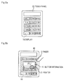
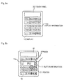
Figures 12a to 12c are diagrams for explaining an example of an operation in another exemplary embodiment ofsmartphone 1 shown inFigure 3 . - As shown in
Figure 12a , in a state in which displayinformation 13a including a numeric keypad of phone numbers is displayed ondisplay 10 ofsmartphone 1 shown inFigure 3 , the finger of the user approaches to display 10, and therebypointer 21 displayed ondisplay 10 stays for a certain time on coordinates (x, y) of the same object ondisplay 10 as shown inFigure 12b . In this case,Tips display 16 as a guide display of an operation when the object is touched is performed as shown inFigure 12c . This may be a pop-up display or a balloon. The example tells the user of a function in which phone numbers are input by simple touch operation, and JKL of the phone book are displayed with long press. - The operation is often unclear unless keys of
touch panel 20 are selected. On the other hand, the mouse of a general personal computer or the like has a function of displaying the guide of the object as Tips, without selecting the object. Because the function is included, the proximity state of the touch panel and the approached (X, Y) coordinates are used to display Tips. As a result, the function of displaying the guide of the key can be realized without operating the touch panel. -
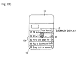
Figures 13a to 13c are diagrams for explaining another example of an operation in another exemplary embodiment ofsmartphone 1 shown inFigure 3 . - As shown in
Figure 13a , in a state in which displayinformation 13b including a plurality of items is displayed ondisplay 10 ofsmartphone 1 shown inFigure 3 , the finger of the user approaches to display 10, and therebypointer 21 displayed ondisplay 10 stays for a certain time at coordinates (x, y) of the same object ondisplay 10 as shown inFigure 13b . In this case, as shown inFigure 13c ,summary display 17 can be indicated, or an item in one layer below may be displayed. - When a list of email is displayed, a text of email can be displayed as Tips. When a list of a phone book is displayed, an item in one layer below may be displayed, or the set content may be displayed.
- Although the present invention has been described with reference to the exemplary embodiments, the present invention is not limited to the exemplary embodiments. Various changes that can be understood by those skilled in the art can be made for the configurations and details of the present invention within the scope of the present invention.
- This application claims the benefit of priority based on Japanese Patent Application No.
2012-33968 filed Feb. 20, 2012
Claims (6)
- A touch panel input device comprising: a display that displays information; a touch panel that is arranged on said display and that detects proximity and contact operation of a contact body; and a controller that controls the display of the information in said display and that receives input according to the contact operation detected at said touch panel, said controller autonomously switching the display in said display, wherein
when said touch panel detects proximity of a contact body, said controller does not switch the display in said display after the detection of the proximity and detection of contact of the contact body with said touch panel, until the contact is no longer detected. - The touch panel input device according to claim 1, wherein
when said touch panel detects proximity of a contact body, said controller does not switch just the display of an area where proximity to the display in said display is detected until said touch panel can no longer detect contact of the contact body. - The touch panel input device according to claim 1, wherein
when said touch panel detects proximity of a contact body in a state in which a plurality of windows are displayed on said display, said controller does not switch just a window displayed in an area where proximity to the window in said display is detected until said touch panel can no longer detect contact of the contact body. - A touch panel input device comprising: a display that displays information; a touch panel that is arranged on said display and that detects proximity and contact operation of a contact body; and a controller that controls the display of the information in said display and that receives input according to the contact operation detected at said touch panel, wherein
when said touch panel detects proximity of a contact body, said controller displays a guide of operation of a case which an area of said touch panel where the approach is detected is contacted. - A control method of a touch panel input device comprising: a display that displays information; a touch panel that is arranged on said display and that detects proximity and contact operation of a contact body; and a controller that controls the display of the information in said display and that receives input according to the contact operation detected at said touch panel, said controller autonomously switching the display in said display, wherein
when said touch panel detects proximity of a contact body, the display in said display is not switched after the detection of the proximity and detection of contact of the contact body at said touch panel, until the contact is no longer detected. - A control method of a touch panel input device comprising: a display that displays information; a touch panel that is arranged on said display and that detects proximity and contact operation of a contact body; and a controller that controls the display of the information in said display and that receives input according to the contact operation detected at said touch panel, wherein
when said touch panel detects proximity of a contact body, a guide of operation of a case of which an area of said touch panel where the approach is detected is contacted is displayed.
Priority Applications (1)
| Application Number | Priority Date | Filing Date | Title |
|---|---|---|---|
| EP16200866.8A EP3179347A1 (en) | 2012-02-20 | 2012-11-06 | Touch panel input device and control method of the touch panel input device |
Applications Claiming Priority (2)
| Application Number | Priority Date | Filing Date | Title |
|---|---|---|---|
| JP2012033968 | 2012-02-20 | ||
| PCT/JP2012/078665 WO2013125103A1 (en) | 2012-02-20 | 2012-11-06 | Touch panel input device and control method for same |
Related Child Applications (2)
| Application Number | Title | Priority Date | Filing Date |
|---|---|---|---|
| EP16200866.8A Division-Into EP3179347A1 (en) | 2012-02-20 | 2012-11-06 | Touch panel input device and control method of the touch panel input device |
| EP16200866.8A Division EP3179347A1 (en) | 2012-02-20 | 2012-11-06 | Touch panel input device and control method of the touch panel input device |
Publications (3)
| Publication Number | Publication Date |
|---|---|
| EP2818984A1 true EP2818984A1 (en) | 2014-12-31 |
| EP2818984A4 EP2818984A4 (en) | 2015-10-07 |
| EP2818984B1 EP2818984B1 (en) | 2017-10-25 |
Family
ID=49005304
Family Applications (2)
| Application Number | Title | Priority Date | Filing Date |
|---|---|---|---|
| EP12869135.9A Not-in-force EP2818984B1 (en) | 2012-02-20 | 2012-11-06 | Touch panel input device and control method for same |
| EP16200866.8A Withdrawn EP3179347A1 (en) | 2012-02-20 | 2012-11-06 | Touch panel input device and control method of the touch panel input device |
Family Applications After (1)
| Application Number | Title | Priority Date | Filing Date |
|---|---|---|---|
| EP16200866.8A Withdrawn EP3179347A1 (en) | 2012-02-20 | 2012-11-06 | Touch panel input device and control method of the touch panel input device |
Country Status (4)
| Country | Link |
|---|---|
| US (1) | US20150338975A1 (en) |
| EP (2) | EP2818984B1 (en) |
| JP (1) | JP6044631B2 (en) |
| WO (1) | WO2013125103A1 (en) |
Families Citing this family (7)
| Publication number | Priority date | Publication date | Assignee | Title |
|---|---|---|---|---|
| JP2014119875A (en) * | 2012-12-14 | 2014-06-30 | Nec Saitama Ltd | Electronic apparatus, operation input device, operation input processing method, and program |
| JP2015007949A (en) * | 2013-06-26 | 2015-01-15 | ソニー株式会社 | Display device, display controlling method, and computer program |
| US20160253088A1 (en) * | 2013-12-05 | 2016-09-01 | Mitsubishi Electric Corporation | Display control apparatus and display control method |
| US10915234B2 (en) * | 2016-06-01 | 2021-02-09 | Motorola Mobility Llc | Responsive, visual presentation of informational briefs on user requested topics |
| JP6737239B2 (en) * | 2017-06-05 | 2020-08-05 | 京セラドキュメントソリューションズ株式会社 | Display device and display control program |
| JP7216053B2 (en) * | 2020-08-27 | 2023-01-31 | Necパーソナルコンピュータ株式会社 | Information processing device, its notification control method, and notification control program |
| JP7893107B2 (en) * | 2022-09-26 | 2026-07-22 | 富士フイルムビジネスイノベーション株式会社 | Information processing device and information processing program |
Family Cites Families (18)
| Publication number | Priority date | Publication date | Assignee | Title |
|---|---|---|---|---|
| JPH0575944A (en) * | 1991-09-10 | 1993-03-26 | Sony Corp | Television receiver |
| US6084582A (en) * | 1997-07-02 | 2000-07-04 | Microsoft Corporation | Method and apparatus for recording a voice narration to accompany a slide show |
| US20050110756A1 (en) * | 2003-11-21 | 2005-05-26 | Hall Bernard J. | Device and method for controlling symbols displayed on a display device |
| JP2007280316A (en) | 2006-04-12 | 2007-10-25 | Xanavi Informatics Corp | Touch panel input device |
| KR20070121180A (en) * | 2006-06-21 | 2007-12-27 | 삼성전자주식회사 | Preview method of print document |
| JP2009026155A (en) * | 2007-07-20 | 2009-02-05 | Toshiba Corp | Input display device and mobile radio terminal device |
| KR101452765B1 (en) * | 2008-05-16 | 2014-10-21 | 엘지전자 주식회사 | Mobile communication terminal using proximity touch and its information input method |
| US8525802B2 (en) * | 2008-03-31 | 2013-09-03 | Lg Electronics Inc. | Portable terminal capable of sensing proximity touch and method for providing graphic user interface using the same |
| US9030418B2 (en) * | 2008-06-24 | 2015-05-12 | Lg Electronics Inc. | Mobile terminal capable of sensing proximity touch |
| KR101504201B1 (en) * | 2008-07-02 | 2015-03-19 | 엘지전자 주식회사 | Mobile terminal and method for displaying keypad thereof |
| JP4683126B2 (en) * | 2008-12-26 | 2011-05-11 | ブラザー工業株式会社 | Input device |
| US8890819B2 (en) * | 2009-03-31 | 2014-11-18 | Mitsubishi Electric Corporation | Display input device and vehicle-mounted information equipment |
| JP5471137B2 (en) * | 2009-08-05 | 2014-04-16 | ソニー株式会社 | Display device, display method, and program |
| JP2011134273A (en) * | 2009-12-25 | 2011-07-07 | Sony Corp | Information processor, information processing method, and program |
| JP2011134272A (en) * | 2009-12-25 | 2011-07-07 | Sony Corp | Information processor, information processing method, and program |
| JP5556423B2 (en) * | 2010-01-29 | 2014-07-23 | ブラザー工業株式会社 | Input device and input control program |
| JP2011253468A (en) * | 2010-06-03 | 2011-12-15 | Aisin Aw Co Ltd | Display device, display method and display program |
| JP5617603B2 (en) * | 2010-12-21 | 2014-11-05 | ソニー株式会社 | Display control apparatus, display control method, and program |
-
2012
- 2012-11-06 US US14/379,863 patent/US20150338975A1/en not_active Abandoned
- 2012-11-06 EP EP12869135.9A patent/EP2818984B1/en not_active Not-in-force
- 2012-11-06 WO PCT/JP2012/078665 patent/WO2013125103A1/en not_active Ceased
- 2012-11-06 JP JP2014500867A patent/JP6044631B2/en not_active Expired - Fee Related
- 2012-11-06 EP EP16200866.8A patent/EP3179347A1/en not_active Withdrawn
Also Published As
| Publication number | Publication date |
|---|---|
| US20150338975A1 (en) | 2015-11-26 |
| JP6044631B2 (en) | 2016-12-14 |
| WO2013125103A1 (en) | 2013-08-29 |
| JPWO2013125103A1 (en) | 2015-07-30 |
| EP2818984B1 (en) | 2017-10-25 |
| EP2818984A4 (en) | 2015-10-07 |
| EP3179347A1 (en) | 2017-06-14 |
Similar Documents
| Publication | Publication Date | Title |
|---|---|---|
| US10175878B2 (en) | Electronic apparatus | |
| EP2818984B1 (en) | Touch panel input device and control method for same | |
| US9684448B2 (en) | Device input system and method for visually impaired users | |
| EP2416233A1 (en) | Information processing apparatus, information processing method, and computer program | |
| JP2013069190A (en) | Portable information terminal, touch operation control method, and program | |
| JP2009151718A (en) | Information processing apparatus and display control method | |
| JP5779156B2 (en) | Information input device, input method thereof, and computer-executable program | |
| TWI659353B (en) | Electronic apparatus and method for operating thereof | |
| EP2455850B1 (en) | Method for scrolling screen in touch screen terminal and device thereof | |
| CN107621899B (en) | Information processing apparatus, misoperation suppression method, and computer-readable storage medium | |
| WO2011118602A1 (en) | Mobile terminal with touch panel function and input method for same | |
| US9298364B2 (en) | Mobile electronic device, screen control method, and storage medium strong screen control program | |
| KR20140106801A (en) | Apparatus and method for supporting voice service in terminal for visually disabled peoples | |
| KR101833281B1 (en) | Method and apparatus preventing malfunction of touchpad in electronic device | |
| KR101434495B1 (en) | A terminal having a touch screen and a method of inputting the character | |
| JP2012113645A (en) | Electronic apparatus | |
| JP2011192173A (en) | Information processor and touch panel operation method | |
| EP2741194A1 (en) | Scroll jump interface for touchscreen input/output device | |
| KR101140508B1 (en) | Method for inputing a character in Terminal having Touch Screen | |
| KR20100097358A (en) | Method for processing widget in portable electronic device with touch-screen | |
| JP2014211853A (en) | Information processing apparatus, information processing method, program, and information processing system | |
| JP2012084181A (en) | Information processor and entry method | |
| KR20110093050A (en) | User interface device by detecting touch area increase and decrease and control method thereof | |
| KR20100042762A (en) | Method of performing mouse interface in portable terminal and the portable terminal | |
| US20150106764A1 (en) | Enhanced Input Selection |
Legal Events
| Date | Code | Title | Description |
|---|---|---|---|
| PUAI | Public reference made under article 153(3) epc to a published international application that has entered the european phase |
Free format text: ORIGINAL CODE: 0009012 |
|
| 17P | Request for examination filed |
Effective date: 20140807 |
|
| AK | Designated contracting states |
Kind code of ref document: A1 Designated state(s): AL AT BE BG CH CY CZ DE DK EE ES FI FR GB GR HR HU IE IS IT LI LT LU LV MC MK MT NL NO PL PT RO RS SE SI SK SM TR |
|
| AX | Request for extension of the european patent |
Extension state: BA ME |
|
| DAX | Request for extension of the european patent (deleted) | ||
| RAP1 | Party data changed (applicant data changed or rights of an application transferred) |
Owner name: NEC CORPORATION |
|
| RA4 | Supplementary search report drawn up and despatched (corrected) |
Effective date: 20150907 |
|
| RIC1 | Information provided on ipc code assigned before grant |
Ipc: G06F 3/048 20130101ALI20150901BHEP Ipc: G06F 3/0488 20130101ALI20150901BHEP Ipc: G06F 3/041 20060101AFI20150901BHEP |
|
| 17Q | First examination report despatched |
Effective date: 20160727 |
|
| GRAP | Despatch of communication of intention to grant a patent |
Free format text: ORIGINAL CODE: EPIDOSNIGR1 |
|
| INTG | Intention to grant announced |
Effective date: 20170516 |
|
| GRAS | Grant fee paid |
Free format text: ORIGINAL CODE: EPIDOSNIGR3 |
|
| GRAA | (expected) grant |
Free format text: ORIGINAL CODE: 0009210 |
|
| AK | Designated contracting states |
Kind code of ref document: B1 Designated state(s): AL AT BE BG CH CY CZ DE DK EE ES FI FR GB GR HR HU IE IS IT LI LT LU LV MC MK MT NL NO PL PT RO RS SE SI SK SM TR |
|
| REG | Reference to a national code |
Ref country code: GB Ref legal event code: FG4D |
|
| RIN1 | Information on inventor provided before grant (corrected) |
Inventor name: SHIMA, YOSHIKAZU |
|
| REG | Reference to a national code |
Ref country code: CH Ref legal event code: EP |
|
| REG | Reference to a national code |
Ref country code: AT Ref legal event code: REF Ref document number: 940495 Country of ref document: AT Kind code of ref document: T Effective date: 20171115 |
|
| REG | Reference to a national code |
Ref country code: IE Ref legal event code: FG4D |
|
| REG | Reference to a national code |
Ref country code: DE Ref legal event code: R096 Ref document number: 602012039066 Country of ref document: DE |
|
| REG | Reference to a national code |
Ref country code: NL Ref legal event code: MP Effective date: 20171025 |
|
| REG | Reference to a national code |
Ref country code: LT Ref legal event code: MG4D |
|
| REG | Reference to a national code |
Ref country code: AT Ref legal event code: MK05 Ref document number: 940495 Country of ref document: AT Kind code of ref document: T Effective date: 20171025 |
|
| PG25 | Lapsed in a contracting state [announced via postgrant information from national office to epo] |
Ref country code: NL Free format text: LAPSE BECAUSE OF FAILURE TO SUBMIT A TRANSLATION OF THE DESCRIPTION OR TO PAY THE FEE WITHIN THE PRESCRIBED TIME-LIMIT Effective date: 20171025 |
|
| PG25 | Lapsed in a contracting state [announced via postgrant information from national office to epo] |
Ref country code: LT Free format text: LAPSE BECAUSE OF FAILURE TO SUBMIT A TRANSLATION OF THE DESCRIPTION OR TO PAY THE FEE WITHIN THE PRESCRIBED TIME-LIMIT Effective date: 20171025 Ref country code: FI Free format text: LAPSE BECAUSE OF FAILURE TO SUBMIT A TRANSLATION OF THE DESCRIPTION OR TO PAY THE FEE WITHIN THE PRESCRIBED TIME-LIMIT Effective date: 20171025 Ref country code: ES Free format text: LAPSE BECAUSE OF FAILURE TO SUBMIT A TRANSLATION OF THE DESCRIPTION OR TO PAY THE FEE WITHIN THE PRESCRIBED TIME-LIMIT Effective date: 20171025 Ref country code: SE Free format text: LAPSE BECAUSE OF FAILURE TO SUBMIT A TRANSLATION OF THE DESCRIPTION OR TO PAY THE FEE WITHIN THE PRESCRIBED TIME-LIMIT Effective date: 20171025 Ref country code: NO Free format text: LAPSE BECAUSE OF FAILURE TO SUBMIT A TRANSLATION OF THE DESCRIPTION OR TO PAY THE FEE WITHIN THE PRESCRIBED TIME-LIMIT Effective date: 20180125 |
|
| PG25 | Lapsed in a contracting state [announced via postgrant information from national office to epo] |
Ref country code: BG Free format text: LAPSE BECAUSE OF FAILURE TO SUBMIT A TRANSLATION OF THE DESCRIPTION OR TO PAY THE FEE WITHIN THE PRESCRIBED TIME-LIMIT Effective date: 20180125 Ref country code: GR Free format text: LAPSE BECAUSE OF FAILURE TO SUBMIT A TRANSLATION OF THE DESCRIPTION OR TO PAY THE FEE WITHIN THE PRESCRIBED TIME-LIMIT Effective date: 20180126 Ref country code: AT Free format text: LAPSE BECAUSE OF FAILURE TO SUBMIT A TRANSLATION OF THE DESCRIPTION OR TO PAY THE FEE WITHIN THE PRESCRIBED TIME-LIMIT Effective date: 20171025 Ref country code: LV Free format text: LAPSE BECAUSE OF FAILURE TO SUBMIT A TRANSLATION OF THE DESCRIPTION OR TO PAY THE FEE WITHIN THE PRESCRIBED TIME-LIMIT Effective date: 20171025 Ref country code: IS Free format text: LAPSE BECAUSE OF FAILURE TO SUBMIT A TRANSLATION OF THE DESCRIPTION OR TO PAY THE FEE WITHIN THE PRESCRIBED TIME-LIMIT Effective date: 20180225 Ref country code: RS Free format text: LAPSE BECAUSE OF FAILURE TO SUBMIT A TRANSLATION OF THE DESCRIPTION OR TO PAY THE FEE WITHIN THE PRESCRIBED TIME-LIMIT Effective date: 20171025 Ref country code: HR Free format text: LAPSE BECAUSE OF FAILURE TO SUBMIT A TRANSLATION OF THE DESCRIPTION OR TO PAY THE FEE WITHIN THE PRESCRIBED TIME-LIMIT Effective date: 20171025 |
|
| REG | Reference to a national code |
Ref country code: DE Ref legal event code: R119 Ref document number: 602012039066 Country of ref document: DE |
|
| PG25 | Lapsed in a contracting state [announced via postgrant information from national office to epo] |
Ref country code: EE Free format text: LAPSE BECAUSE OF FAILURE TO SUBMIT A TRANSLATION OF THE DESCRIPTION OR TO PAY THE FEE WITHIN THE PRESCRIBED TIME-LIMIT Effective date: 20171025 Ref country code: CY Free format text: LAPSE BECAUSE OF FAILURE TO SUBMIT A TRANSLATION OF THE DESCRIPTION OR TO PAY THE FEE WITHIN THE PRESCRIBED TIME-LIMIT Effective date: 20171025 Ref country code: DK Free format text: LAPSE BECAUSE OF FAILURE TO SUBMIT A TRANSLATION OF THE DESCRIPTION OR TO PAY THE FEE WITHIN THE PRESCRIBED TIME-LIMIT Effective date: 20171025 Ref country code: SK Free format text: LAPSE BECAUSE OF FAILURE TO SUBMIT A TRANSLATION OF THE DESCRIPTION OR TO PAY THE FEE WITHIN THE PRESCRIBED TIME-LIMIT Effective date: 20171025 Ref country code: MC Free format text: LAPSE BECAUSE OF FAILURE TO SUBMIT A TRANSLATION OF THE DESCRIPTION OR TO PAY THE FEE WITHIN THE PRESCRIBED TIME-LIMIT Effective date: 20171025 Ref country code: CH Free format text: LAPSE BECAUSE OF NON-PAYMENT OF DUE FEES Effective date: 20171130 Ref country code: CZ Free format text: LAPSE BECAUSE OF FAILURE TO SUBMIT A TRANSLATION OF THE DESCRIPTION OR TO PAY THE FEE WITHIN THE PRESCRIBED TIME-LIMIT Effective date: 20171025 Ref country code: LI Free format text: LAPSE BECAUSE OF NON-PAYMENT OF DUE FEES Effective date: 20171130 |
|
| PG25 | Lapsed in a contracting state [announced via postgrant information from national office to epo] |
Ref country code: SM Free format text: LAPSE BECAUSE OF FAILURE TO SUBMIT A TRANSLATION OF THE DESCRIPTION OR TO PAY THE FEE WITHIN THE PRESCRIBED TIME-LIMIT Effective date: 20171025 Ref country code: PL Free format text: LAPSE BECAUSE OF FAILURE TO SUBMIT A TRANSLATION OF THE DESCRIPTION OR TO PAY THE FEE WITHIN THE PRESCRIBED TIME-LIMIT Effective date: 20171025 Ref country code: IT Free format text: LAPSE BECAUSE OF FAILURE TO SUBMIT A TRANSLATION OF THE DESCRIPTION OR TO PAY THE FEE WITHIN THE PRESCRIBED TIME-LIMIT Effective date: 20171025 Ref country code: RO Free format text: LAPSE BECAUSE OF FAILURE TO SUBMIT A TRANSLATION OF THE DESCRIPTION OR TO PAY THE FEE WITHIN THE PRESCRIBED TIME-LIMIT Effective date: 20171025 Ref country code: LU Free format text: LAPSE BECAUSE OF NON-PAYMENT OF DUE FEES Effective date: 20171106 |
|
| PLBE | No opposition filed within time limit |
Free format text: ORIGINAL CODE: 0009261 |
|
| REG | Reference to a national code |
Ref country code: FR Ref legal event code: ST Effective date: 20180731 Ref country code: BE Ref legal event code: MM Effective date: 20171130 |
|
| STAA | Information on the status of an ep patent application or granted ep patent |
Free format text: STATUS: NO OPPOSITION FILED WITHIN TIME LIMIT |
|
| REG | Reference to a national code |
Ref country code: IE Ref legal event code: MM4A |
|
| GBPC | Gb: european patent ceased through non-payment of renewal fee |
Effective date: 20180125 |
|
| PG25 | Lapsed in a contracting state [announced via postgrant information from national office to epo] |
Ref country code: MT Free format text: LAPSE BECAUSE OF NON-PAYMENT OF DUE FEES Effective date: 20171106 |
|
| 26N | No opposition filed |
Effective date: 20180726 |
|
| PG25 | Lapsed in a contracting state [announced via postgrant information from national office to epo] |
Ref country code: DE Free format text: LAPSE BECAUSE OF NON-PAYMENT OF DUE FEES Effective date: 20180602 Ref country code: IE Free format text: LAPSE BECAUSE OF NON-PAYMENT OF DUE FEES Effective date: 20171106 Ref country code: FR Free format text: LAPSE BECAUSE OF NON-PAYMENT OF DUE FEES Effective date: 20171226 |
|
| PG25 | Lapsed in a contracting state [announced via postgrant information from national office to epo] |
Ref country code: SI Free format text: LAPSE BECAUSE OF FAILURE TO SUBMIT A TRANSLATION OF THE DESCRIPTION OR TO PAY THE FEE WITHIN THE PRESCRIBED TIME-LIMIT Effective date: 20171025 Ref country code: GB Free format text: LAPSE BECAUSE OF NON-PAYMENT OF DUE FEES Effective date: 20180125 Ref country code: BE Free format text: LAPSE BECAUSE OF NON-PAYMENT OF DUE FEES Effective date: 20171130 |
|
| PG25 | Lapsed in a contracting state [announced via postgrant information from national office to epo] |
Ref country code: HU Free format text: LAPSE BECAUSE OF FAILURE TO SUBMIT A TRANSLATION OF THE DESCRIPTION OR TO PAY THE FEE WITHIN THE PRESCRIBED TIME-LIMIT; INVALID AB INITIO Effective date: 20121106 |
|
| PG25 | Lapsed in a contracting state [announced via postgrant information from national office to epo] |
Ref country code: MK Free format text: LAPSE BECAUSE OF FAILURE TO SUBMIT A TRANSLATION OF THE DESCRIPTION OR TO PAY THE FEE WITHIN THE PRESCRIBED TIME-LIMIT Effective date: 20171025 |
|
| PG25 | Lapsed in a contracting state [announced via postgrant information from national office to epo] |
Ref country code: TR Free format text: LAPSE BECAUSE OF FAILURE TO SUBMIT A TRANSLATION OF THE DESCRIPTION OR TO PAY THE FEE WITHIN THE PRESCRIBED TIME-LIMIT Effective date: 20171025 |
|
| PG25 | Lapsed in a contracting state [announced via postgrant information from national office to epo] |
Ref country code: PT Free format text: LAPSE BECAUSE OF FAILURE TO SUBMIT A TRANSLATION OF THE DESCRIPTION OR TO PAY THE FEE WITHIN THE PRESCRIBED TIME-LIMIT Effective date: 20171025 |
|
| PG25 | Lapsed in a contracting state [announced via postgrant information from national office to epo] |
Ref country code: AL Free format text: LAPSE BECAUSE OF FAILURE TO SUBMIT A TRANSLATION OF THE DESCRIPTION OR TO PAY THE FEE WITHIN THE PRESCRIBED TIME-LIMIT Effective date: 20171025 |