EP2818857A1 - Apparatus and method for eddy current inspection of structures - Google Patents
Apparatus and method for eddy current inspection of structures Download PDFInfo
- Publication number
- EP2818857A1 EP2818857A1 EP14172178.7A EP14172178A EP2818857A1 EP 2818857 A1 EP2818857 A1 EP 2818857A1 EP 14172178 A EP14172178 A EP 14172178A EP 2818857 A1 EP2818857 A1 EP 2818857A1
- Authority
- EP
- European Patent Office
- Prior art keywords
- eddy current
- see
- probe apparatus
- annular cavity
- elements
- Prior art date
- Legal status (The legal status is an assumption and is not a legal conclusion. Google has not performed a legal analysis and makes no representation as to the accuracy of the status listed.)
- Granted
Links
Images





Classifications
-
- G—PHYSICS
- G01—MEASURING; TESTING
- G01N—INVESTIGATING OR ANALYSING MATERIALS BY DETERMINING THEIR CHEMICAL OR PHYSICAL PROPERTIES
- G01N27/00—Investigating or analysing materials by the use of electric, electrochemical, or magnetic means
- G01N27/72—Investigating or analysing materials by the use of electric, electrochemical, or magnetic means by investigating magnetic variables
- G01N27/82—Investigating or analysing materials by the use of electric, electrochemical, or magnetic means by investigating magnetic variables for investigating the presence of flaws
- G01N27/90—Investigating or analysing materials by the use of electric, electrochemical, or magnetic means by investigating magnetic variables for investigating the presence of flaws using eddy currents
-
- G—PHYSICS
- G01—MEASURING; TESTING
- G01N—INVESTIGATING OR ANALYSING MATERIALS BY DETERMINING THEIR CHEMICAL OR PHYSICAL PROPERTIES
- G01N27/00—Investigating or analysing materials by the use of electric, electrochemical, or magnetic means
- G01N27/72—Investigating or analysing materials by the use of electric, electrochemical, or magnetic means by investigating magnetic variables
- G01N27/82—Investigating or analysing materials by the use of electric, electrochemical, or magnetic means by investigating magnetic variables for investigating the presence of flaws
- G01N27/90—Investigating or analysing materials by the use of electric, electrochemical, or magnetic means by investigating magnetic variables for investigating the presence of flaws using eddy currents
- G01N27/9013—Arrangements for scanning
- G01N27/902—Arrangements for scanning by moving the sensors
Definitions
- the disclosure relates generally to devices and methods for non-destructive inspection (NDI) of structures, and more particularly, to devices and methods for eddy current NDI of annular cavities, such as tapered, annular cavities, of structures of air vehicles.
- NDI non-destructive inspection
- Non-destructive inspection (NDI) of a structure typically involves inspecting the structure without having to significantly disassemble the structure and without causing harm to the structure.
- NDI is often used to inspect air vehicle structures, such as aircraft and rotorcraft structures, to detect any internal or external damage to the structures, for example, cracks, crack formations, corrosion, impact damage, or other types of internal or external damage, and to validate the structural health of such structures.
- NDI may be useful for inspecting and detecting cracks or crack formations in structures of an aircraft, such as annular cavities or bores of terminal fitting structures that attach aircraft wings to the aircraft.
- Known NDI devices and methods exist for inspecting and detecting cracks or crack formations in annular cavities or bores of terminal fitting structures of an aircraft.
- one such known NDI method of inspection and detection of cracks or crack formations of such annular cavities or bores of terminal fitting structures includes applying a fluorescent penetrant material to the interior of the annular cavity or bore of the terminal fitting structure to be inspected and observing with a black light any fluorescent penetrant material that flows into a crack or crack formation.
- a fluorescent penetrant material typically requires that the interior of the annular cavity or bore of the terminal fitting structure be initially manually cleaned to remove any paint, grease, or other surface contaminants.
- Such manual cleaning of the interior of the annular cavity or bore of the terminal fitting structure to be inspected may prove challenging where the inspection area is difficult to manually access and/or observe.
- such known method of using a fluorescent penetrant material typically requires several applications of fluorescent penetrant to the interior of the annular cavity or bore, and several subsequent removals of excess fluorescent penetrant material from the interior of the annular cavity or bore, of the terminal fitting structure to be inspected.
- Such applications and subsequent removals of excess fluorescent penetrant material may be difficult to visually observe and may result in cracks or crack formations being missed by visual inspection.
- such applications and subsequent removals of excess fluorescent penetrant material may be labor intensive and time consuming to perform, which may, in turn, result in increased costs for conducting such known NDI method.
- a known eddy current NDI method exists for inspecting and detecting cracks or crack formations in annular cavities or bores of terminal fitting structures of an aircraft.
- Eddy current testing with an eddy current surface probe is based on inducing electron flow (eddy currents) in electrically conductive material. Any defect in the material, such as cracks or other discontinuities, may disrupt the flow of the eddy currents. Higher frequency signals may be used to detect surface or near-surface flaws, and lower frequencies may be used for deeper, subsurface defect detection.
- Such known eddy current NDI method involves manually holding a single eddy current coil against the interior of the annular cavity or bore of a terminal fitting structure and attempting to maintain a normalcy of the single eddy current coil to the annular cavity or bore, while scanning and indexing a known eddy current surface probe around the annular cavity or bore, and while watching a signal display on or connected to the known eddy current surface probe.
- a probe apparatus comprising a first end configured to connect to a rotating scanner device.
- the probe apparatus further comprises a second end.
- the second end comprises two or more eddy current elements.
- the second end further comprises a positioning mechanism configured to position the two or more eddy current elements against cavity walls of an annular cavity of a structure to be inspected with the probe apparatus, when the probe apparatus is positioned within the annular cavity.
- the second end further comprises an aligning mechanism coupled to the positioning mechanism.
- the aligning mechanism is configured to align the two or more eddy current elements in a perpendicular position with respect to the cavity walls of the annular cavity, when the probe apparatus is positioned within the annular cavity.
- a probe apparatus for eddy current inspection of a tapered, annular cavity of a structure of an air vehicle.
- the probe apparatus comprises a connector end configured to connect to a rotating scanner device.
- the probe apparatus further comprises a sensor end connected to the connector end via a body portion.
- the sensor end comprises three foot portions.
- the sensor end further comprises two eddy current elements comprising a reference eddy current coil attached to one foot portion and a test eddy current coil attached to another foot portion.
- the sensor end further comprises a positioning mechanism configured to position the two or more eddy current elements against cavity walls of a tapered, annular cavity of a structure of an air vehicle to be inspected with the probe apparatus, when the probe apparatus is positioned within the tapered, annular cavity.
- the sensor end further comprises an aligning mechanism coupled to the positioning mechanism.
- the aligning mechanism is configured to align the two or more eddy current elements in a perpendicular position with respect to the cavity walls of the tapered, annular cavity, when the probe apparatus is positioned within the tapered, annular cavity.
- a differential method of performing an eddy current inspection of an annular cavity of a structure comprises the step of attaching a rotating scanner device to a connector end of a probe apparatus.
- the probe apparatus comprises a sensor end having two or more eddy current elements, a positioning mechanism, and an aligning mechanism.
- the method further comprises the step of inserting the probe apparatus into an annular cavity of a structure to be inspected and rotating the probe apparatus with the rotating scanner device.
- the method further comprises the step of positioning with the positioning mechanism the two or more eddy current elements against cavity walls of the annular cavity to be inspected with the probe apparatus.
- the method further comprises the step of aligning with the aligning mechanism the two or more eddy current elements, so that each of the two or more eddy current elements is in a perpendicular position with respect to the cavity walls of the annular cavity to be inspected with the probe apparatus.
- the method further comprises the step of emitting and receiving signals to and from the two or more eddy current elements and the rotating scanner device to obtain data providing an indication of structural health of the structure.
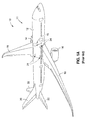
- FIG. 1A is an illustration of a perspective view of a known air vehicle 10, such as in the form of an aircraft 11, having one or more structures 24 that may be inspected using embodiments of a probe apparatus 70 (see FIGS. 4-8 ) and a method 150 (see FIG. 9 ) of the disclosure.
- the air vehicle 10 such as in the form of aircraft 11, comprises a fuselage 12, one or more propulsion units 14, a wing box 16, wings 18, a tail vertical stabilizer 20, and tail horizontal stabilizers 22.
- the aircraft 11 shown in FIG. 1A is generally representative of a commercial passenger aircraft having one or more structures 24 that may be inspected using embodiments of the probe apparatus 70 (see FIGS.
- the teachings of the disclosed embodiments of the probe apparatus 70 (see FIGS. 4-8 ) and the method 150 (see FIG. 9 ) may be equally applicable to inspection of structures 24 on other air vehicles 10, such as cargo aircraft, military aircraft, rotorcraft such as helicopters, and other suitable types of air vehicles.
- the inspection of the one or more structures 24 (see FIG. 1A ) performed with the probe apparatus 70 (see FIGS. 4-8 ) and the method 150 (see FIG. 9 ) is non-destructive inspection (NDI) involving inspection of the one or more structures 24 (see FIG. 1A ) without having to significantly disassemble the structures 24 and without causing harm to the structures 24, in order to detect any internal or external damage to the structures 24, for example, cracks or crack formations, and to validate the structural health of the structures 24.
- NDI non-destructive inspection
- Embodiments of the probe apparatus 70 (see FIGS. 4-8 ) and the method 150 (see FIG. 9 ) of the disclosure may preferably be used for non-destructive inspection and detection of cracks or crack formations in structures 24 (see FIG.
- FIG. 1B of an aircraft 11 (see FIG. 1A ), such as terminal fittings 26 (see FIG. 1B ) of the wing box 16 (see FIG. 1A ) that attach wings 18 (see FIG. 1A ) to the aircraft 11 (see FIG. 1A ), and in particular, in annular cavities 28 (see FIG. 1B ) or bores, such as tapered, annular cavities 28a (see FIG. 1B ) or bores, of or formed in the terminal fittings 26 (see FIG. 1B ).
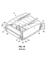
- FIG. 1B is an illustration of a close-up, perspective view of the known wing box 16 of FIG. 1A having structures 24, such as terminal fittings 26, that may be inspected with embodiments of the probe apparatus 70 (see FIGS. 4-8 ) and the method 150 (see FIG. 9 ) of the disclosure.
- FIG. 1B shows terminal fittings 26, such as in the form of forward terminal fittings 26a and aft terminal fitting 26b, where each terminal fitting 26 has an annular cavity 28 or bore, such as in the form of a tapered, annular cavity 28a or bore.
- embodiments of the probe apparatus 70 may be inserted into the annular cavity 28 (see FIG. 1B ) or bore, such as in the form of a tapered, annular cavity 28a or bore, to perform non-destructive inspection.
- FIG. 1C is an illustration of a close-up, cutaway, perspective view of the known wing box 16 of FIG. 1B having structure 24, such as terminal fitting 26, in the form of forward terminal fitting 26a, with the annular cavity 28 or bore, such as the tapered, annular cavity 28a or bore, that may be inspected with embodiments of the probe apparatus 70 (see FIGS. 4-8 ) and the method 150 (see FIG. 9 ) of the disclosure.
- FIG. 2 is an illustration of a flow diagram of an embodiment of an aircraft manufacturing and service method 30 of the disclosure.
- FIG. 3 is an illustration of a functional block diagram of an embodiment of an aircraft 50 of the disclosure. Referring to FIGS. 2-3 , embodiments of the disclosure may be described in the context of the aircraft manufacturing and service method 30 as shown in FIG. 2 and the aircraft 50 as shown in FIG. 3 .
- exemplary aircraft manufacturing and service method 30 may include specification and design 32 of the aircraft 50 and material procurement 34.
- component and subassembly manufacturing 36 and system integration 38 of the aircraft 50 takes place. Thereafter, the aircraft 50 may go through certification and delivery 40 in order to be placed in service 42. While in service 42 by a customer, the aircraft 50 may be scheduled for routine maintenance and service 44 (which may also include modification, reconfiguration, refurbishment, and other suitable services).
- Each of the processes of the aircraft manufacturing and service method 30 may be performed or carried out by a system integrator, a third party, and/or an operator (e.g., a customer).
- a system integrator may include, without limitation, any number of aircraft manufacturers and major-system subcontractors
- a third party may include, without limitation, any number of vendors, subcontractors, and suppliers
- an operator may include an airline, leasing company, military entity, service organization, and other suitable operators.
- the aircraft 50 produced by the exemplary aircraft manufacturing and service method 30 may include an airframe 52 with a plurality of systems 54 and an interior 56.
- the plurality of systems 54 may include one or more of a propulsion system 58, an electrical system 60, a hydraulic system 62, and an environmental system 64. Any number of other systems may be included.
- an aerospace example is shown, the principles of the invention may be applied to other industries, such as the automotive industry.
- Methods and systems embodied herein may be employed during any one or more of the stages of the aircraft manufacturing and service method 30.
- components or subassemblies corresponding to component and subassembly manufacturing 36 may be fabricated or manufactured in a manner similar to components or subassemblies produced while the aircraft 50 is in service.
- one or more apparatus embodiments, method embodiments, or a combination thereof may be utilized during component and subassembly manufacturing 36 and system integration 38, for example, by substantially expediting assembly of or reducing the cost of the aircraft 50.
- one or more of apparatus embodiments, method embodiments, or a combination thereof may be utilized while the aircraft 50 is in service, for example and without limitation, to maintenance and service 44.
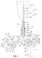
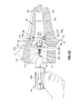
- FIG. 4 is an illustration of a side perspective view of an embodiment of the probe apparatus 70, such as in the form of an eddy current inspection probe apparatus 70a, of the disclosure.
- the probe apparatus 70 comprises a first end 72, a second end 74, and a body portion 76.
- the first end 72 (see FIG. 4 ) is preferably configured to connect to a rotating scanner device 80 (see FIG. 4 ), such as a known eddy current inspection rotating scanner device 80a (see FIG. 5 ).
- the first end 72 comprises a connector end 72a having a connector plug 78 configured to connect to the rotating scanner device 80.
- the second end 74 (see FIG. 4 ) comprises a sensor end 74a (see FIG. 4 ).
- the second end 74 in the form of sensor end 74a (see FIG. 4 ), comprises two or more eddy current elements 86 (see FIG. 4 ).
- the two or more eddy current elements 86 preferably comprise eddy current coils, such as in the form of at least one reference eddy current coil 86a, and at least one test eddy current coil 86b.
- Each of the two or more eddy current elements 86 preferably comprise two or more electromagnetic coil elements 87 (see FIG. 4 ). As shown in FIG.
- the electromagnetic coil elements 87 of the eddy current elements 86 are preferably connected to the rotating scanner device 80 via excitation and signal wiring 113 that runs from each of the electromagnetic coil elements 87, through foot portions 90, along positioning arm elements 100a, through shaft element 112, to the connector end 72a, and to the rotating scanner device 80.
- the probe apparatus 70 further comprises three or more foot portions 90.
- the probe apparatus 70 has three foot portions 90.
- the probe apparatus 70 may have four foot portions 90 or another suitable number of foot portions 90.
- each foot portion 90 may comprise a mounting element 91 attached to a base element 96.
- the mounting element 91 preferably has a first side 88 configured for attachment and mounting of an eddy current element 86 to the mounting element 91 of the foot portion 90, and preferably has a second side 94 configured for attachment and mounting of the base element 96 to the mounting element 91.
- FIG. 4 the mounting element 91 preferably has a first side 88 configured for attachment and mounting of an eddy current element 86 to the mounting element 91 of the foot portion 90, and preferably has a second side 94 configured for attachment and mounting of the base element 96 to the mounting element 91.
- the mounting element 91 may have one or more attachment elements 92, such as in the form of a bolt or screw, configured to attach the eddy current element 86 to the mounting element 91 of the foot portion 90.
- each foot portion 90 is preferably coupled to a positioning mechanism 100, and each foot portion 90 is preferably coupled to an aligning mechanism 98.
- the reference eddy current coil 86a having electromagnetic coil elements 87 is preferably attached to one foot portion 90 of the three or more foot portions 90, and the test eddy current coil 86b having electromagnetic coil elements 87 is preferably attached to another separate foot portion 90 of the three or more foot portions 90.
- the electromagnetic coil elements 87 of both the reference eddy current coil 86a (see FIG. 4 ) and the test eddy current coil 86b (see FIG. 4 ) may be attached to one eddy current element 86, and the one eddy current element 86 may be attached to one foot portion 90 of the three or more foot portions 90.
- the second end 74 further comprises the positioning mechanism 100 configured to position the two or more eddy current elements 86 against cavity walls 115 (see FIG. 6B ) of an annular cavity 28 (see FIG. 6B ) or bore of a structure 24 (see FIG. 1A ), such as a terminal fitting 26 (see FIG. 6B ) to be inspected with the probe apparatus 70 (see FIG. 4 ), when the probe apparatus 70 is positioned within the annular cavity 28 (see FIG. 6B ) or bore.
- the positioning mechanism 100 preferably comprises three or more positioning arm elements 100a configured to expand and contract about a fulcrum member 104 of the probe apparatus 70.
- the positioning mechanism 100 has three positioning arm elements 100a (see FIG. 4 ).
- the positioning mechanism 100 may have four positioning arm elements 100a, or another suitable number of positioning arm elements 100a.
- each positioning arm element 100a may be angled outwardly.
- each positioning arm element 100a has a first end 102a coupled to the aligning mechanism 98 and the foot portion 90.
- each positioning arm element 100a has a second end 102b coupled to a cone member 106 of the body portion 76 of the probe apparatus 70.
- the cone member 106 (see FIG. 4 ) is preferably spring-loaded via an elastic element 108 (see FIG. 4 ), such as in the form of a spring 108a (see FIG. 4 ), and controls the tension of the positioning arm elements 100a (see FIG. 4 ).
- the tension and diameter adjustment of the positioning arm elements 100a are preferably determined by the position of an adjusting element 110 (see FIG. 4 ), such as in the form of a knurled nut 110a (see FIG. 4 ), positioned on the shaft element 112 (see FIG. 4 ), such as in the form of a threaded central shaft element 112a (see FIG. 4 ).
- a threaded member 114 (see FIG. 4 ) for adjustable movement of the adjusting element 110 is preferably positioned on the shaft element 112 (see FIG. 4 ) adjacent the adjusting element 110 (see FIG. 4 ).
- the second end 74 such as in the form of sensor end 74a, further comprises the aligning mechanism 98 coupled to the positioning mechanism 100.
- the aligning mechanism 98 is configured to align the two or more eddy current elements 86 (see FIG. 4 ) in a perpendicular position with respect to cavity walls 115 (see FIG. 6B ) of the annular cavity 28 (see FIG. 6B ), such as in the form of tapered, annular cavity 28a (see FIG. 1B ), when the probe apparatus 70 is positioned within the annular cavity 28.
- FIG. 4 the aligning mechanism 98 coupled to the positioning mechanism 100.
- the aligning mechanism 98 is configured to align the two or more eddy current elements 86 (see FIG. 4 ) in a perpendicular position with respect to cavity walls 115 (see FIG. 6B ) of the annular cavity 28 (see FIG. 6B ), such as in the form of tapered, annular cavity 28a (see FIG. 1B ), when the probe apparatus 70 is positioned within the annul
- the aligning mechanism 98 preferably comprises three or more pivot joint mechanisms 98a each configured to rotate one of the three or more foot portions 90 to maintain alignment of the two or more eddy current elements 86 in the perpendicular position with respect to the cavity walls 115 (see FIG. 6B ) of the annular cavity 28 (see FIG. 6B ).
- Each pivot joint mechanism 98a preferably comprises a pivot slot 97 (see FIG. 4 ) configured for movement of a pivot pin member 99 (see FIG. 4 ) within the pivot slot 97 in order to rotate or swivel the foot portion 90 on the pivot joint mechanism 98a (see FIG. 4 ), while the positioning arm element 100a (see FIG. 4 ) expands and contracts to accommodate for diameter changes.
- FIG. 5 is an illustration of a partial side perspective view of the probe apparatus 70, such as in the form of eddy current inspection probe apparatus 70a, of FIG. 4 , attached to an embodiment of a rotating scanner device 80.
- the rotating scanner device 80 (see FIGS. 5 , 8 ) comprises a known eddy current inspection rotating scanner device 80a, such as, for example, a hand-held differential bridge eddy current inspection rotating scanner device, for emitting and receiving signals to and from the two or more eddy current elements 86 (see FIG. 4 ).
- the rotating scanner device 80 has an attachment end 82 for receiving and attaching to the first end 72, such as in the form of connector end 72a (see FIG. 4 ), of the probe apparatus 70.
- the rotating scanner device 80 has a grip portion 84 so that an operator may manually grip or hold the rotating scanner 80 and attached probe apparatus 70 during inspection of the structure 24 (see FIG. 1A ).
- the probe apparatus 70 is designed to fit with and connect to known, commercial semi-automatic bolt-hole rotating scanner devices, such as obtained from Olympus Corporation of Tokyo, Japan, or obtained from UniWest of Pasco, Washington.
- suitable rotating scanner devices such as known eddy current inspection rotating scanner devices, may also be used.
- such known rotating scanner devices 80 that may be used with the probe apparatus 70 disclosed herein have a frequency range of from about 100 Hz (Hertz) to about 6 MHz (Megahertz), and a speed range of from about 600 rpm (revolutions per minute) to about 3000 rpm.
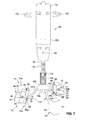
- FIG. 7 is an illustration showing rotation of an embodiment of the rotating scanner device 80 of FIG. 5 attached to an embodiment of the probe apparatus 70 of FIG. 4 shown in a side perspective view.
- FIG. 7 shows the rotating scanner device 80, such as in the form of eddy current inspection rotating scanner device 80a, (see also FIG. 5 ) which emits and receives signals to and from the two or more eddy current elements 86 (see FIG. 7 ).
- the rotating scanner device 80 has attachment end 82 for attachment to the probe apparatus 70.
- the rotating scanner device 80 may have an LED (light-emitting diode) alarm indicator 130 and may further have an activation end 134.
- the semi-automated rotating scanner device 80 may be activated to rotate the attached probe apparatus 70 in a rotational direction indicated by arrows 132 (see FIG. 7 ).
- FIG. 8 is an illustration showing rotation of another embodiment of a rotating scanner device 80, such as in the form of eddy current inspection rotating scanner device 80b, attached to another embodiment of the probe apparatus 70, such as in the form of eddy current inspection probe apparatus 70b, shown in a side perspective view.
- the rotating scanner device 80 comprises attachment end 82 and body portion 136.
- the semi-automated rotating scanner device 80 may be activated to rotate the attached probe apparatus 70 in a rotational direction indicated by arrows 138 (see FIG. 8 ).
- FIG. 8 is an illustration showing rotation of another embodiment of a rotating scanner device 80, such as in the form of eddy current inspection rotating scanner device 80b, attached to another embodiment of the probe apparatus 70, such as in the form of eddy current inspection probe apparatus 70b, shown in a side perspective view.
- the rotating scanner device 80 comprises attachment end 82 and body portion 136.
- the semi-automated rotating scanner device 80 may be activated to rotate the attached probe apparatus 70 in a rotational direction indicated by arrow
- the electromagnetic coil elements 87 of both the reference eddy current coil 86a (see FIG. 4 ) and the test eddy current coil 86b (see FIG. 4 ) are attached to one eddy current element 86 , and the one eddy current element 86 is attached to one foot portion 90 of the three or more foot portions 90.
- FIG. 6A is an illustration of a top perspective view of an embodiment of a probe apparatus 70 attached to an embodiment of a rotating scanner device 80, such as eddy current inspection rotating scanner device 80a, having an attachment end 82 attached to the first end 72 of the probe apparatus 70, and having grip portion 84 for handheld use by an operator.
- the probe apparatus 70 is inserted at a first position 116 in an annular cavity 28 of a structure 24 (see FIG. 1A ), such as a terminal fitting 26 (see FIG. 6A ), to be inspected.
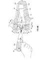
- FIG. 6B is an illustration of a side perspective view of the probe apparatus 70 and attached rotating scanner device 80 of FIG. 6A inserted at the first position 116 in the annular cavity 28 which is shown in cross-section.
- FIG. 6C is an illustration of a side perspective view of the probe apparatus 70 and attached rotating scanner device 80 of FIG. 6A inserted at a second position 118 in the annular cavity 28 which is shown in cross-section.
- the first end 72 such as in the form of connector end 72a (see FIG. 4 ) with connector plug 78 (see FIG. 4 ), connects or plugs into the rotating scanner device 80 and provides excitation and signal return to and from two eddy current elements 86 (see also FIG. 4 ) having the electromagnetic coil elements 87.
- each eddy current element 86 is mounted to the mounting element 91 of the foot portion 90 and each eddy current element 86 is attached to the mounting element 91 via attachment element 92.
- the probe apparatus 70 operates in a differential method where one eddy current element 86 is a reference eddy current coil 86a (see FIG.
- the eddy current elements 86 are preferably kept normal to the surface of the annular cavity 28, such as the tapered, annular cavity 28a (see FIG. 1B ), due to the foot portions 90 (see FIGS. 6A-6C ) rotating or swiveling on the pivot joint mechanism 98a (see FIG. 6A ) while the positioning arm elements 100a of the positioning mechanism 100 (see FIGS. 6A-6C ) expand and contract to accommodate for the diameter changes of the tapered, annular cavity 28a.
- the positioning arm elements 100a see FIG.
- the cone member 106 controls the tension of the positioning arm elements 100a.
- the tension and diameter adjustment are preferably determined by the position of the adjusting element 110 (see FIG. 6A ) which may be adjustable on threaded member 114 (see FIG. 6A ).
- Any crack or crack formation in the annular cavity 28 (see FIG. 6A ) which is oriented perpendicular to the scanning direction of the eddy current element 86 (see FIGS. 6A-6C ) may preferably be detected as an upward signal on the rotating scanner device 80 (see FIGS. 6A-6C ).
- the semi-automated rotating scanner device 80 (see FIGS. 6A-6C ) is activated to rotate and the probe apparatus 70 may be inserted into the annular cavity 28 (see FIG. 6A ), such as the tapered, annular cavity 28a (see FIG. 1B ), at the first position 116 (see FIGS. 6A-6B ) in an entry and first bushing installation area 120 (see FIG. 6B ).
- the probe apparatus 70 may then be inserted down the annular cavity 28 (see FIG. 6C ), such as the tapered, annular cavity 28a (see FIG. 1B ), at the second position 118 (see FIG. 6C ) in a tapered inspection area 122 (see FIG.
- the annular cavity 28 of the terminal fitting 28 may further have a second bushing installation area 124 for a bushing 126 and an internal end 128 of the annular cavity 128.
- the probe apparatus 70 preferably performs the inspection in the tapered inspection area 122 (see FIG. 6C ) and is preferably not inserted beyond the tapered inspection 122 into the second bushing installation area 124.
- the probe apparatus 70 is preferably excited with an alternating current and induces an eddy current in the annular cavity 28, such as the tapered, annular cavity 28a (see FIG. 1B ), of the terminal fitting 26 (see FIG. 6A ) being inspected.
- Any discontinuities or material property variations that change the eddy current flow in the annular cavity 28, such as the tapered, annular cavity 28a (see FIG. 1B ), of the terminal fitting 26 (see FIG. 6A ) are preferably detected by the probe apparatus 70 as a potential defect, such as a crack or crack formation.
- the probe apparatus 70 (see FIG. 7 ) comprises a connector end 72a (see FIG. 4 ) configured to connect to a rotating scanner device 80 (see FIG. 7 ).
- the rotating scanner device 80 (see FIG. 7 ) preferably comprises an eddy current inspection rotating scanner device 80a (see FIG. 7 ) for emitting and receiving signals to and from a reference eddy current coil 86a (see FIG. 4 ) and a test eddy current coil 86b (see FIG. 4 ).
- the probe apparatus 70 further comprises a sensor end 74a (see FIG. 7 ) connected to the connector end 72a (see FIG. 4 ) via a body portion 76 (see FIG. 4 ).
- the sensor end 74a (see FIG. 7 ) comprises three foot portions 90 (see FIG. 7 ).
- the sensor end 74a (see FIG. 7 ) further comprises two eddy current elements 86 (see FIG. 7 ) comprising the reference eddy current coil 86a (see FIG. 4 ) attached to one foot portion 90 (see FIG. 7 ) and the test eddy current coil 86b (see FIG. 4 ) attached to another foot portion 90 (see FIG. 7 ).
- the sensor end 74 (see FIG. 7 )
- the positioning mechanism 100 further comprises the positioning mechanism 100 (see FIG. 7 ) configured to position the two or more eddy current elements 86 (see FIG. 7 ) against cavity walls 115 (see FIG. 6B ) of a tapered, annular cavity 28a (see FIG. 1B ) of a structure 24 (see FIG. 1A ) of an air vehicle 10 (see FIG. 1A ), such as an aircraft 11 (see FIG. 1A ), to be inspected with the probe apparatus 70 (see FIG. 7 ), when the probe apparatus 70 is positioned within the tapered, annular cavity 28a (see FIG. 1B ).
- the positioning mechanism 100 preferably comprises three positioning arm elements 100a (see FIG. 7 ) configured to expand and contract about the fulcrum member 104 (see FIG. 7 ) of the probe apparatus 70 (see FIG. 7 ).
- the sensor end 74 further comprises the aligning mechanism 98 (see FIG. 7 ) coupled to the positioning mechanism 100 (see FIG. 7 ).
- the aligning mechanism 98 (see FIG. 7 ) is preferably configured to align the two or more eddy current elements 86 (see FIG. 7 ) in a perpendicular position with respect to the cavity walls 115 (see FIG. 6B ) of the tapered, annular cavity 28a (see FIG. 1B ), when the probe apparatus 70 (see FIG. 7 ) is positioned within the tapered, annular cavity 28.
- the aligning mechanism 98 preferably comprises three pivot joint mechanisms 98a (see FIG. 7 ) each configured to rotate one of the three foot portions 90 (see FIG.
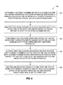
- FIG. 9 is a flow diagram illustrating an embodiment of the method 150 of the disclosure.
- the method 150 comprises step 152 of attaching a rotating scanner device 80 (see FIGS. 5 , 8 ), such as in the form of an eddy current inspection rotating scanner device 80a, to a connector end 72a (see FIG. 4 ) of a probe apparatus 70 (see FIGS. 4-8 ).
- the probe apparatus 70 (see FIGS. 4-8 ) comprises a sensor end 74a (see FIG. 4 ) having two or more eddy current elements 86 (see FIG. 4 ), a positioning mechanism 100 (see FIG. 4 ), and an aligning mechanism 98 (see FIG. 4 ).
- the attaching step 152 further comprises attaching an eddy current inspection rotating scanner device 80a (see FIG. 7 ) or 80b (see FIG. 8 ) to the connector end 72a (see FIG. 4 ).
- the rotating scanner device 80 (see FIGS. 5 , 8 ), such as in the form of the eddy current inspection rotating scanner device 80a, is a hand-held differential bridge eddy current inspection rotating scanner device.
- the attaching step 152 further comprises attaching a reference eddy current coil 86a (see FIG. 4 ) with electromagnetic coil elements 87 (see FIG. 4 ) to one foot portion 90 (see FIG. 4 ), and attaching a test eddy current coil 86b (see FIG. 4 ) with electromagnetic coil elements 87 (see FIG.
- the attaching step 152 further comprises attaching the electromagnetic coil elements 87 (see FIG. 8 ) of both the reference eddy current coil 86a and the test eddy current coil 86b to one eddy current element 86 (see FIG. 8 ) and attaching the one eddy current element (see FIG. 8 ) to one foot portion 90 (see FIG. 8 ).
- the method 150 comprises step 154 of inserting the probe apparatus into an annular cavity 28 (see FIG. 6A ), such as the tapered annular cavity 28a (see FIG. 1B ) of the structure 24 (see FIG. 1B ), such as the terminal fitting 26 (see FIG. 6A ), to be inspected and rotating the probe apparatus 70 (see FIGS. 4-8 ) with the rotating scanner device (see FIGS. 5 , 8 ).
- the inserting step 154 further comprises inserting the probe apparatus 70 (see FIGS. 4-8 ) into a tapered annular cavity 28a (see FIG. 1B ) of the structure 24 (see FIG. 1B ), such as a terminal fitting 26 (see FIG. 6A ), where the tapered annular cavity 28a (see FIG. 1B ) preferably has an outer diameter of greater than about two inches, and more preferably has an outer diameter of greater than about two inches and less than about six inches.
- the method 150 comprises step 156 of positioning with the positioning mechanism 100 (see FIG. 4 ) the two or more eddy current elements 86 (see FIG. 4 ) against cavity walls 115 (see FIG. 6B ) of the annular cavity 28 (see FIG. 6A ) to be inspected with the probe apparatus 70 (see FIGS. 4-8 ).
- the positioning step 156 further comprises positioning the two or more eddy current elements 86 (see FIG. 4 ) with three or more positioning arm elements 100a (see FIG. 4 ), each positioning arm element 100a configured to expand and contract about a fulcrum member 104 (see FIG. 4 ) of the probe apparatus 70 (see FIGS. 4-8 ).
- the method 150 comprises step 158 of aligning with the aligning mechanism 98 (see FIG. 4 ) the two or more eddy current elements 86 (see FIG. 4 ), so that each of the two or more eddy current elements 86 (see FIG. 4 ) is in a perpendicular position with respect to the cavity walls 115 (see FIG. 6B ) of the annular cavity 28 (see FIG. 6B ) to be inspected with the probe apparatus 70 (see FIGS. 4-8 ).
- the aligning step 158 further comprises aligning with three or more pivot joint mechanisms 98a (see FIG. 4 ), each pivot joint mechanism 98a configured to rotate one foot portion 90 (see FIG. 4 ) of the three or more foot portions 90 (see FIG.
- each foot portion 90 being coupled to the aligning mechanism 98, to maintain alignment of the two or more eddy current elements 86 (see FIG. 4 ) in the perpendicular position with respect to the cavity walls 115 (see FIG. 6B ) of the annular cavity 28 (see FIG. 6B ).
- the method 150 comprises step 160 of emitting and receiving signals to and from the two or more eddy current elements 86 (see FIG. 4 ) and the rotating scanner device 80 (see FIGS. 7 , 8 ) to obtain data providing an indication of structural health of the structure 24 (see FIG. 1B ), such as a terminal fitting 26 (see FIG. 6A ).
- the emitting and receiving signals step 160 further comprises detecting as an upward signal on the rotating scanner device 80 (see FIGS. 7 , 8 ) any crack or crack formation in the annular cavity 28 (see FIG. 6B ) oriented perpendicular to a scanning direction of the two or more eddy current elements 86 (see FIG. 4 ).
- Disclosed embodiments of the probe apparatus 70 (see FIGS. 4-8 ) and method 150 (see FIG. 9 ) allow for improved non-destructive inspection (NDI) of inspection areas that may be difficult to access and that may be difficult to visually observe the inspection procedure and results. This may result in improved detection of cracks and crack formations in critical areas, such as terminal fittings 26 (see FIG. 1B ), that attach the wings 18 (see FIG. 1A ) to an aircraft 11 (see FIG. 1A ).
- NDI non-destructive inspection
- FIG. 9 Disclosed embodiments of the probe apparatus 70 (see FIGS. 4-8 ) and method 150 (see FIG. 9 ) allow for improved non-destructive inspection (NDI) of inspection areas that may be difficult to access and that may be difficult to visually observe the inspection procedure and results. This may result in improved detection of cracks and crack formations in critical areas, such as terminal fittings 26 (see FIG. 1B ), that attach the wings 18 (see FIG. 1A ) to an aircraft 11 (see FIG.
- one eddy current element 86 is a reference eddy current coil 86a (see FIG. 4 ) and another eddy current element 86 (see FIG. 4 ) is a test eddy current coil 86b (see FIG. 4 ).
- probe apparatus 70 see FIGS. 4-8 and method 150 (see FIG. 9 ) allow for the probe apparatus 70 (see FIGS. 4-8 ) to be attached to existing commercial rotating scanner devices 80 (see FIGS. 7 , 8 ), such as eddy current inspection rotating scanner devices 80a (see FIG. 7 ) and 80b (see FIG. 8 ), for example, a hand-held differential bridge eddy current inspection rotating scanner device, and inserted into the tapered, annular cavity 28a (see FIG. 1B ) or bore.
- existing commercial rotating scanner devices 80 see FIGS. 7 , 8
- eddy current inspection rotating scanner devices 80a see FIG. 7
- 80b see FIG. 8
- a hand-held differential bridge eddy current inspection rotating scanner device for example, a hand-held differential bridge eddy current inspection rotating scanner device, and inserted into the tapered, annular cavity 28a (see FIG. 1B ) or bore.
- the configuration of the probe apparatus 70 allows the eddy current elements 86 (see FIG.
- the method 150 allows for semi-automated inspection of the tapered annular cavity 28a (see FIG. 1B ) or bore with the only access needed being for the probe apparatus 70 (see FIGS. 4-8 ) and an operator's hand.
Landscapes
- Chemical & Material Sciences (AREA)
- Chemical Kinetics & Catalysis (AREA)
- Electrochemistry (AREA)
- Physics & Mathematics (AREA)
- Health & Medical Sciences (AREA)
- Life Sciences & Earth Sciences (AREA)
- Analytical Chemistry (AREA)
- Biochemistry (AREA)
- General Health & Medical Sciences (AREA)
- General Physics & Mathematics (AREA)
- Immunology (AREA)
- Pathology (AREA)
- Investigating Or Analyzing Materials By The Use Of Magnetic Means (AREA)
Abstract
Description
- The disclosure relates generally to devices and methods for non-destructive inspection (NDI) of structures, and more particularly, to devices and methods for eddy current NDI of annular cavities, such as tapered, annular cavities, of structures of air vehicles.
- Non-destructive inspection (NDI) of a structure typically involves inspecting the structure without having to significantly disassemble the structure and without causing harm to the structure. NDI is often used to inspect air vehicle structures, such as aircraft and rotorcraft structures, to detect any internal or external damage to the structures, for example, cracks, crack formations, corrosion, impact damage, or other types of internal or external damage, and to validate the structural health of such structures. In particular, NDI may be useful for inspecting and detecting cracks or crack formations in structures of an aircraft, such as annular cavities or bores of terminal fitting structures that attach aircraft wings to the aircraft.
- Known NDI devices and methods exist for inspecting and detecting cracks or crack formations in annular cavities or bores of terminal fitting structures of an aircraft. For example, one such known NDI method of inspection and detection of cracks or crack formations of such annular cavities or bores of terminal fitting structures includes applying a fluorescent penetrant material to the interior of the annular cavity or bore of the terminal fitting structure to be inspected and observing with a black light any fluorescent penetrant material that flows into a crack or crack formation. However, such known method of using a fluorescent penetrant material typically requires that the interior of the annular cavity or bore of the terminal fitting structure be initially manually cleaned to remove any paint, grease, or other surface contaminants. Such manual cleaning of the interior of the annular cavity or bore of the terminal fitting structure to be inspected may prove challenging where the inspection area is difficult to manually access and/or observe. In addition, such known method of using a fluorescent penetrant material typically requires several applications of fluorescent penetrant to the interior of the annular cavity or bore, and several subsequent removals of excess fluorescent penetrant material from the interior of the annular cavity or bore, of the terminal fitting structure to be inspected. Such applications and subsequent removals of excess fluorescent penetrant material may be difficult to visually observe and may result in cracks or crack formations being missed by visual inspection. Moreover, such applications and subsequent removals of excess fluorescent penetrant material may be labor intensive and time consuming to perform, which may, in turn, result in increased costs for conducting such known NDI method.
- In addition, a known eddy current NDI method exists for inspecting and detecting cracks or crack formations in annular cavities or bores of terminal fitting structures of an aircraft. Eddy current testing with an eddy current surface probe is based on inducing electron flow (eddy currents) in electrically conductive material. Any defect in the material, such as cracks or other discontinuities, may disrupt the flow of the eddy currents. Higher frequency signals may be used to detect surface or near-surface flaws, and lower frequencies may be used for deeper, subsurface defect detection. Such known eddy current NDI method involves manually holding a single eddy current coil against the interior of the annular cavity or bore of a terminal fitting structure and attempting to maintain a normalcy of the single eddy current coil to the annular cavity or bore, while scanning and indexing a known eddy current surface probe around the annular cavity or bore, and while watching a signal display on or connected to the known eddy current surface probe. However, such manual holding of the single eddy current coil, while scanning and indexing with the eddy current surface probe and watching the signal display, may prove challenging due to difficulty in manually accessing the interior of the annular cavity or bore of the terminal fitting structure to be inspected, and due to difficulty in maintaining the single eddy current coil normal to the interior surface of the cavity or bore of the terminal fitting structure to be inspected. These difficulties may be compounded when such known eddy current NDI method is conducted in large diameter, non-cylindrical, annular cavities or bores, such as tapered, annular cavities or bores, that are to be inspected. Moreover, it may be difficult and/or time-consuming to position and place the single eddy current coil against the tapered, annular cavity or bore of the terminal fitting structure to be inspected, due to the difficulty in manually accessing the often tight area and due to the necessity that the single eddy current coil be in proper alignment against the tapered, annular cavity or bore of the terminal fitting structure to be inspected.
- Accordingly, there is a need in the art for an improved NDI apparatus and method for eddy current inspection of structures that provide advantages over known devices and methods.
- This need for an improved NDI apparatus and method for eddy current inspection of structures is satisfied by this disclosure. As discussed in the below detailed description, embodiments of the improved NDI apparatus and method for eddy current inspection of structures may provide significant advantages over existing devices and methods.
- In an embodiment of the disclosure, there is provided a probe apparatus. The probe apparatus comprises a first end configured to connect to a rotating scanner device. The probe apparatus further comprises a second end. The second end comprises two or more eddy current elements. The second end further comprises a positioning mechanism configured to position the two or more eddy current elements against cavity walls of an annular cavity of a structure to be inspected with the probe apparatus, when the probe apparatus is positioned within the annular cavity. The second end further comprises an aligning mechanism coupled to the positioning mechanism. The aligning mechanism is configured to align the two or more eddy current elements in a perpendicular position with respect to the cavity walls of the annular cavity, when the probe apparatus is positioned within the annular cavity.
- In another embodiment of the disclosure, there is provided a probe apparatus for eddy current inspection of a tapered, annular cavity of a structure of an air vehicle. The probe apparatus comprises a connector end configured to connect to a rotating scanner device. The probe apparatus further comprises a sensor end connected to the connector end via a body portion. The sensor end comprises three foot portions. The sensor end further comprises two eddy current elements comprising a reference eddy current coil attached to one foot portion and a test eddy current coil attached to another foot portion. The sensor end further comprises a positioning mechanism configured to position the two or more eddy current elements against cavity walls of a tapered, annular cavity of a structure of an air vehicle to be inspected with the probe apparatus, when the probe apparatus is positioned within the tapered, annular cavity. The sensor end further comprises an aligning mechanism coupled to the positioning mechanism. The aligning mechanism is configured to align the two or more eddy current elements in a perpendicular position with respect to the cavity walls of the tapered, annular cavity, when the probe apparatus is positioned within the tapered, annular cavity.
- In another embodiment of the disclosure, there is provided a differential method of performing an eddy current inspection of an annular cavity of a structure. The method comprises the step of attaching a rotating scanner device to a connector end of a probe apparatus. The probe apparatus comprises a sensor end having two or more eddy current elements, a positioning mechanism, and an aligning mechanism. The method further comprises the step of inserting the probe apparatus into an annular cavity of a structure to be inspected and rotating the probe apparatus with the rotating scanner device. The method further comprises the step of positioning with the positioning mechanism the two or more eddy current elements against cavity walls of the annular cavity to be inspected with the probe apparatus. The method further comprises the step of aligning with the aligning mechanism the two or more eddy current elements, so that each of the two or more eddy current elements is in a perpendicular position with respect to the cavity walls of the annular cavity to be inspected with the probe apparatus. The method further comprises the step of emitting and receiving signals to and from the two or more eddy current elements and the rotating scanner device to obtain data providing an indication of structural health of the structure.
- The features, functions, and advantages that have been discussed can be achieved independently in various embodiments of the disclosure or may be combined in yet other embodiments further details of which can be seen with reference to the following description and drawings.
- The disclosure can be better understood with reference to the following detailed description taken in conjunction with the accompanying drawings which illustrate preferred and exemplary embodiments, but which are not necessarily drawn to scale, wherein:
-
FIG. 1A is an illustration of a perspective view of an air vehicle having one or more structures that may be inspected with embodiments of a probe apparatus and a method of the disclosure; -
FIG. 1B is an illustration of a close-up, perspective view of a wing box ofFIG. 1A having terminal fittings that may be inspected with embodiments of a probe apparatus and a method of the disclosure; -
FIG. 1C is an illustration of a close-up, cutaway, perspective view of a terminal fitting ofFIG. 1B that may be inspected with embodiments of a probe apparatus and a method of the disclosure; -
FIG. 2 is an illustration of a flow diagram of an embodiment of an aircraft manufacturing and service method of the disclosure; -
FIG. 3 is an illustration of a functional block diagram of an embodiment of an aircraft of the disclosure; -
FIG. 4 is an illustration of a side perspective view of an embodiment of a probe apparatus of the disclosure; -
FIG. 5 is an illustration of a partial side perspective view of the probe apparatus ofFIG. 4 attached to an embodiment of a rotating scanner device; -
FIG. 6A is an illustration of a top perspective view of an embodiment of a probe apparatus attached to an embodiment of a rotating scanner device and inserted at a first position in an annular cavity of a structure to be inspected; -
FIG. 6B is an illustration of a side perspective view of the probe apparatus and attached rotating scanner device ofFIG. 6A inserted at a first position in an annular cavity shown in cross-section; -
FIG. 6C is an illustration of a side perspective view of the probe apparatus and attached rotating scanner device ofFIG. 6A inserted at a second position in an annular cavity shown in cross-section; -
FIG. 7 is an illustration showing rotation of an embodiment of a rotating scanner device attached to an embodiment of a probe apparatus of the disclosure shown in a side perspective view; -
FIG. 8 is an illustration showing rotation of another embodiment of a rotating scanner device attached to another embodiment of a probe apparatus of the disclosure shown in a side perspective view; and, -
FIG. 9 is a flow diagram illustrating an embodiment of a method of the disclosure. - Disclosed embodiments will now be described more fully hereinafter with reference to the accompanying drawings, in which some, but not all of the disclosed embodiments are shown. Indeed, several different embodiments may be provided and should not be construed as limited to the embodiments set forth herein. Rather, these embodiments are provided so that this disclosure will be thorough and will fully convey the scope of the disclosure to those skilled in the art.
- Now referring to the Figures,
FIG. 1A is an illustration of a perspective view of a knownair vehicle 10, such as in the form of anaircraft 11, having one ormore structures 24 that may be inspected using embodiments of a probe apparatus 70 (seeFIGS. 4-8 ) and a method 150 (seeFIG. 9 ) of the disclosure. As shown inFIG. 1A , theair vehicle 10, such as in the form ofaircraft 11, comprises afuselage 12, one ormore propulsion units 14, awing box 16,wings 18, a tailvertical stabilizer 20, and tailhorizontal stabilizers 22. Although theaircraft 11 shown inFIG. 1A is generally representative of a commercial passenger aircraft having one ormore structures 24 that may be inspected using embodiments of the probe apparatus 70 (seeFIGS. 4-8 ) and the method 150 (seeFIG. 9 ) disclosed herein, the teachings of the disclosed embodiments of the probe apparatus 70 (seeFIGS. 4-8 ) and the method 150 (seeFIG. 9 ) may be equally applicable to inspection ofstructures 24 onother air vehicles 10, such as cargo aircraft, military aircraft, rotorcraft such as helicopters, and other suitable types of air vehicles. - Preferably, the inspection of the one or more structures 24 (see
FIG. 1A ) performed with the probe apparatus 70 (seeFIGS. 4-8 ) and the method 150 (seeFIG. 9 ) is non-destructive inspection (NDI) involving inspection of the one or more structures 24 (seeFIG. 1A ) without having to significantly disassemble thestructures 24 and without causing harm to thestructures 24, in order to detect any internal or external damage to thestructures 24, for example, cracks or crack formations, and to validate the structural health of thestructures 24. Embodiments of the probe apparatus 70 (seeFIGS. 4-8 ) and the method 150 (seeFIG. 9 ) of the disclosure may preferably be used for non-destructive inspection and detection of cracks or crack formations in structures 24 (seeFIG. 1B ) of an aircraft 11 (seeFIG. 1A ), such as terminal fittings 26 (seeFIG. 1B ) of the wing box 16 (seeFIG. 1A ) that attach wings 18 (seeFIG. 1A ) to the aircraft 11 (seeFIG. 1A ), and in particular, in annular cavities 28 (seeFIG. 1B ) or bores, such as tapered,annular cavities 28a (seeFIG. 1B ) or bores, of or formed in the terminal fittings 26 (seeFIG. 1B ). -
FIG. 1B is an illustration of a close-up, perspective view of the knownwing box 16 ofFIG. 1A having structures 24, such asterminal fittings 26, that may be inspected with embodiments of the probe apparatus 70 (seeFIGS. 4-8 ) and the method 150 (seeFIG. 9 ) of the disclosure.FIG. 1B showsterminal fittings 26, such as in the form of forwardterminal fittings 26a and aft terminal fitting 26b, where eachterminal fitting 26 has anannular cavity 28 or bore, such as in the form of a tapered,annular cavity 28a or bore. As discussed in detail below, embodiments of the probe apparatus 70 (seeFIGS. 4-8 ) may be inserted into the annular cavity 28 (seeFIG. 1B ) or bore, such as in the form of a tapered,annular cavity 28a or bore, to perform non-destructive inspection. -
FIG. 1C is an illustration of a close-up, cutaway, perspective view of the knownwing box 16 ofFIG. 1B having structure 24, such asterminal fitting 26, in the form of forward terminal fitting 26a, with theannular cavity 28 or bore, such as the tapered,annular cavity 28a or bore, that may be inspected with embodiments of the probe apparatus 70 (seeFIGS. 4-8 ) and the method 150 (seeFIG. 9 ) of the disclosure. -
FIG. 2 is an illustration of a flow diagram of an embodiment of an aircraft manufacturing andservice method 30 of the disclosure.FIG. 3 is an illustration of a functional block diagram of an embodiment of anaircraft 50 of the disclosure. Referring toFIGS. 2-3 , embodiments of the disclosure may be described in the context of the aircraft manufacturing andservice method 30 as shown inFIG. 2 and theaircraft 50 as shown inFIG. 3 . During pre-production, exemplary aircraft manufacturing andservice method 30 may include specification anddesign 32 of theaircraft 50 andmaterial procurement 34. During manufacturing, component andsubassembly manufacturing 36 andsystem integration 38 of theaircraft 50 takes place. Thereafter, theaircraft 50 may go through certification anddelivery 40 in order to be placed inservice 42. While inservice 42 by a customer, theaircraft 50 may be scheduled for routine maintenance and service 44 (which may also include modification, reconfiguration, refurbishment, and other suitable services). - Each of the processes of the aircraft manufacturing and
service method 30 may be performed or carried out by a system integrator, a third party, and/or an operator (e.g., a customer). For the purposes of this description, a system integrator may include, without limitation, any number of aircraft manufacturers and major-system subcontractors; a third party may include, without limitation, any number of vendors, subcontractors, and suppliers; and an operator may include an airline, leasing company, military entity, service organization, and other suitable operators. - As shown in
FIG. 3 , theaircraft 50 produced by the exemplary aircraft manufacturing andservice method 30 may include anairframe 52 with a plurality ofsystems 54 and an interior 56. Examples of the plurality ofsystems 54 may include one or more of apropulsion system 58, anelectrical system 60, ahydraulic system 62, and anenvironmental system 64. Any number of other systems may be included. Although an aerospace example is shown, the principles of the invention may be applied to other industries, such as the automotive industry. - Methods and systems embodied herein may be employed during any one or more of the stages of the aircraft manufacturing and
service method 30. For example, components or subassemblies corresponding to component andsubassembly manufacturing 36 may be fabricated or manufactured in a manner similar to components or subassemblies produced while theaircraft 50 is in service. Also, one or more apparatus embodiments, method embodiments, or a combination thereof, may be utilized during component andsubassembly manufacturing 36 andsystem integration 38, for example, by substantially expediting assembly of or reducing the cost of theaircraft 50. Similarly, one or more of apparatus embodiments, method embodiments, or a combination thereof, may be utilized while theaircraft 50 is in service, for example and without limitation, to maintenance andservice 44. - In an embodiment of the disclosure, as shown in
FIG. 4 , there is provided aprobe apparatus 70.FIG. 4 is an illustration of a side perspective view of an embodiment of theprobe apparatus 70, such as in the form of an eddy currentinspection probe apparatus 70a, of the disclosure. As shown inFIG. 4 , theprobe apparatus 70 comprises afirst end 72, asecond end 74, and abody portion 76. The first end 72 (seeFIG. 4 ) is preferably configured to connect to a rotating scanner device 80 (seeFIG. 4 ), such as a known eddy current inspection rotatingscanner device 80a (seeFIG. 5 ). As further shown inFIG. 4 , thefirst end 72 comprises aconnector end 72a having aconnector plug 78 configured to connect to therotating scanner device 80. - The second end 74 (see
FIG. 4 ) comprises asensor end 74a (seeFIG. 4 ). The second end 74 (seeFIG. 4 ), in the form ofsensor end 74a (seeFIG. 4 ), comprises two or more eddy current elements 86 (seeFIG. 4 ). As shown inFIG. 4 , the two or more eddycurrent elements 86 preferably comprise eddy current coils, such as in the form of at least one referenceeddy current coil 86a, and at least one testeddy current coil 86b. Each of the two or more eddycurrent elements 86 preferably comprise two or more electromagnetic coil elements 87 (seeFIG. 4 ). As shown inFIG. 4 , theelectromagnetic coil elements 87 of the eddycurrent elements 86 are preferably connected to therotating scanner device 80 via excitation andsignal wiring 113 that runs from each of theelectromagnetic coil elements 87, throughfoot portions 90, along positioningarm elements 100a, throughshaft element 112, to theconnector end 72a, and to therotating scanner device 80. - As shown in
FIG. 4 , theprobe apparatus 70 further comprises three ormore foot portions 90. Preferably, theprobe apparatus 70 has threefoot portions 90. However, theprobe apparatus 70 may have fourfoot portions 90 or another suitable number offoot portions 90. As further shown inFIG. 4 , eachfoot portion 90 may comprise a mountingelement 91 attached to abase element 96. As further shown inFIG. 4 , the mountingelement 91 preferably has a first side 88 configured for attachment and mounting of aneddy current element 86 to the mountingelement 91 of thefoot portion 90, and preferably has asecond side 94 configured for attachment and mounting of thebase element 96 to the mountingelement 91. As further shown inFIG. 4 , the mountingelement 91 may have one ormore attachment elements 92, such as in the form of a bolt or screw, configured to attach theeddy current element 86 to the mountingelement 91 of thefoot portion 90. As further shown inFIG. 4 , eachfoot portion 90 is preferably coupled to apositioning mechanism 100, and eachfoot portion 90 is preferably coupled to an aligningmechanism 98. - In one embodiment as shown in
FIG. 4 , the referenceeddy current coil 86a havingelectromagnetic coil elements 87 is preferably attached to onefoot portion 90 of the three ormore foot portions 90, and the testeddy current coil 86b havingelectromagnetic coil elements 87 is preferably attached to anotherseparate foot portion 90 of the three ormore foot portions 90. In another embodiment as shown inFIG. 8 , theelectromagnetic coil elements 87 of both the referenceeddy current coil 86a (seeFIG. 4 ) and the testeddy current coil 86b (seeFIG. 4 ) may be attached to oneeddy current element 86, and the oneeddy current element 86 may be attached to onefoot portion 90 of the three ormore foot portions 90. - As shown in
FIG. 4 , thesecond end 74, such as in the form ofsensor end 74a, further comprises thepositioning mechanism 100 configured to position the two or more eddycurrent elements 86 against cavity walls 115 (seeFIG. 6B ) of an annular cavity 28 (seeFIG. 6B ) or bore of a structure 24 (seeFIG. 1A ), such as a terminal fitting 26 (seeFIG. 6B ) to be inspected with the probe apparatus 70 (seeFIG. 4 ), when theprobe apparatus 70 is positioned within the annular cavity 28 (seeFIG. 6B ) or bore. As further shown inFIG. 4 , thepositioning mechanism 100 preferably comprises three or morepositioning arm elements 100a configured to expand and contract about afulcrum member 104 of theprobe apparatus 70. Preferably, the positioning mechanism 100 (seeFIG. 4 ) has threepositioning arm elements 100a (seeFIG. 4 ). However, thepositioning mechanism 100 may have fourpositioning arm elements 100a, or another suitable number ofpositioning arm elements 100a. As further shown inFIG. 4 , eachpositioning arm element 100a may be angled outwardly. As further shown inFIG. 4 , eachpositioning arm element 100a has afirst end 102a coupled to the aligningmechanism 98 and thefoot portion 90. As further shown inFIG. 4 , eachpositioning arm element 100a has asecond end 102b coupled to acone member 106 of thebody portion 76 of theprobe apparatus 70. - The cone member 106 (see
FIG. 4 ) is preferably spring-loaded via an elastic element 108 (seeFIG. 4 ), such as in the form of aspring 108a (seeFIG. 4 ), and controls the tension of thepositioning arm elements 100a (seeFIG. 4 ). The tension and diameter adjustment of thepositioning arm elements 100a (seeFIG. 4 ) are preferably determined by the position of an adjusting element 110 (seeFIG. 4 ), such as in the form of aknurled nut 110a (seeFIG. 4 ), positioned on the shaft element 112 (seeFIG. 4 ), such as in the form of a threadedcentral shaft element 112a (seeFIG. 4 ). A threaded member 114 (seeFIG. 4 ) for adjustable movement of the adjustingelement 110 is preferably positioned on the shaft element 112 (seeFIG. 4 ) adjacent the adjusting element 110 (seeFIG. 4 ). - As shown in
FIG. 4 , thesecond end 74, such as in the form ofsensor end 74a, further comprises the aligningmechanism 98 coupled to thepositioning mechanism 100. The aligningmechanism 98 is configured to align the two or more eddy current elements 86 (seeFIG. 4 ) in a perpendicular position with respect to cavity walls 115 (seeFIG. 6B ) of the annular cavity 28 (seeFIG. 6B ), such as in the form of tapered,annular cavity 28a (seeFIG. 1B ), when theprobe apparatus 70 is positioned within theannular cavity 28. As further shown inFIG. 4 , the aligningmechanism 98 preferably comprises three or more pivotjoint mechanisms 98a each configured to rotate one of the three ormore foot portions 90 to maintain alignment of the two or more eddycurrent elements 86 in the perpendicular position with respect to the cavity walls 115 (seeFIG. 6B ) of the annular cavity 28 (seeFIG. 6B ). Each pivotjoint mechanism 98a (seeFIG. 4 ) preferably comprises a pivot slot 97 (seeFIG. 4 ) configured for movement of a pivot pin member 99 (seeFIG. 4 ) within thepivot slot 97 in order to rotate or swivel thefoot portion 90 on the pivotjoint mechanism 98a (seeFIG. 4 ), while thepositioning arm element 100a (seeFIG. 4 ) expands and contracts to accommodate for diameter changes. -
FIG. 5 is an illustration of a partial side perspective view of theprobe apparatus 70, such as in the form of eddy currentinspection probe apparatus 70a, ofFIG. 4 , attached to an embodiment of arotating scanner device 80. Preferably, the rotating scanner device 80 (seeFIGS. 5 ,8 ) comprises a known eddy current inspection rotatingscanner device 80a, such as, for example, a hand-held differential bridge eddy current inspection rotating scanner device, for emitting and receiving signals to and from the two or more eddy current elements 86 (seeFIG. 4 ). As shown inFIG. 5 , the rotatingscanner device 80 has anattachment end 82 for receiving and attaching to thefirst end 72, such as in the form ofconnector end 72a (seeFIG. 4 ), of theprobe apparatus 70. As further shown inFIG. 5 , the rotatingscanner device 80 has agrip portion 84 so that an operator may manually grip or hold the rotatingscanner 80 and attachedprobe apparatus 70 during inspection of the structure 24 (seeFIG. 1A ). Preferably, theprobe apparatus 70 is designed to fit with and connect to known, commercial semi-automatic bolt-hole rotating scanner devices, such as obtained from Olympus Corporation of Tokyo, Japan, or obtained from UniWest of Pasco, Washington. However, other suitable rotating scanner devices, such as known eddy current inspection rotating scanner devices, may also be used. Preferably, such knownrotating scanner devices 80 that may be used with theprobe apparatus 70 disclosed herein have a frequency range of from about 100 Hz (Hertz) to about 6 MHz (Megahertz), and a speed range of from about 600 rpm (revolutions per minute) to about 3000 rpm. -
FIG. 7 is an illustration showing rotation of an embodiment of therotating scanner device 80 ofFIG. 5 attached to an embodiment of theprobe apparatus 70 ofFIG. 4 shown in a side perspective view.FIG. 7 shows therotating scanner device 80, such as in the form of eddy current inspection rotatingscanner device 80a, (see alsoFIG. 5 ) which emits and receives signals to and from the two or more eddy current elements 86 (seeFIG. 7 ). As shown inFIG. 7 , the rotatingscanner device 80 hasattachment end 82 for attachment to theprobe apparatus 70. As further shown inFIG. 7 , the rotatingscanner device 80 may have an LED (light-emitting diode)alarm indicator 130 and may further have anactivation end 134. When the probe apparatus 70 (seeFIG. 6A ) is inserted into the annular cavity 28 (seeFIG. 6A ), the semi-automatedrotating scanner device 80 may be activated to rotate the attachedprobe apparatus 70 in a rotational direction indicated by arrows 132 (seeFIG. 7 ). -
FIG. 8 is an illustration showing rotation of another embodiment of arotating scanner device 80, such as in the form of eddy current inspection rotatingscanner device 80b, attached to another embodiment of theprobe apparatus 70, such as in the form of eddy currentinspection probe apparatus 70b, shown in a side perspective view. As shown inFIG. 8 , the rotatingscanner device 80 comprisesattachment end 82 andbody portion 136. When the probe apparatus 70 (seeFIG. 8 ) is inserted into the annular cavity 28 (seeFIG. 1B ), the semi-automatedrotating scanner device 80 may be activated to rotate the attachedprobe apparatus 70 in a rotational direction indicated by arrows 138 (seeFIG. 8 ). As further shown inFIG. 8 , in this embodiment, theelectromagnetic coil elements 87 of both the referenceeddy current coil 86a (seeFIG. 4 ) and the testeddy current coil 86b (seeFIG. 4 ) are attached to oneeddy current element 86 , and the oneeddy current element 86 is attached to onefoot portion 90 of the three ormore foot portions 90. -
FIG. 6A is an illustration of a top perspective view of an embodiment of aprobe apparatus 70 attached to an embodiment of arotating scanner device 80, such as eddy current inspection rotatingscanner device 80a, having anattachment end 82 attached to thefirst end 72 of theprobe apparatus 70, and havinggrip portion 84 for handheld use by an operator. As shown inFIG. 6A , theprobe apparatus 70 is inserted at afirst position 116 in anannular cavity 28 of a structure 24 (seeFIG. 1A ), such as a terminal fitting 26 (seeFIG. 6A ), to be inspected. -
FIG. 6B is an illustration of a side perspective view of theprobe apparatus 70 and attachedrotating scanner device 80 ofFIG. 6A inserted at thefirst position 116 in theannular cavity 28 which is shown in cross-section.FIG. 6C is an illustration of a side perspective view of theprobe apparatus 70 and attachedrotating scanner device 80 ofFIG. 6A inserted at asecond position 118 in theannular cavity 28 which is shown in cross-section. - As shown in
FIG. 6A , thefirst end 72, such as in the form ofconnector end 72a (seeFIG. 4 ) with connector plug 78 (seeFIG. 4 ), connects or plugs into therotating scanner device 80 and provides excitation and signal return to and from two eddy current elements 86 (see alsoFIG. 4 ) having theelectromagnetic coil elements 87. As shown inFIG. 6A , eacheddy current element 86 is mounted to the mountingelement 91 of thefoot portion 90 and eacheddy current element 86 is attached to the mountingelement 91 viaattachment element 92. Theprobe apparatus 70 operates in a differential method where oneeddy current element 86 is a referenceeddy current coil 86a (seeFIG. 6B ) and the othereddy current element 86 is a testeddy current coil 86b (seeFIG. 6B ). This configuration allows for non-relevant geometry and surface conditions to be ignored. The eddycurrent elements 86 are preferably kept normal to the surface of theannular cavity 28, such as the tapered,annular cavity 28a (seeFIG. 1B ), due to the foot portions 90 (seeFIGS. 6A-6C ) rotating or swiveling on the pivotjoint mechanism 98a (seeFIG. 6A ) while thepositioning arm elements 100a of the positioning mechanism 100 (seeFIGS. 6A-6C ) expand and contract to accommodate for the diameter changes of the tapered,annular cavity 28a. Thepositioning arm elements 100a (seeFIG. 4 ) of the positioning mechanism 100 (seeFIG. 6A ) expand and contract around the fulcrum member 104 (seeFIG. 6A ). The cone member 106 (seeFIG. 6A ), which is spring-loaded via elastic element 108 (seeFIG. 6A ), controls the tension of thepositioning arm elements 100a. The tension and diameter adjustment are preferably determined by the position of the adjusting element 110 (seeFIG. 6A ) which may be adjustable on threaded member 114 (seeFIG. 6A ). Any crack or crack formation in the annular cavity 28 (seeFIG. 6A ) which is oriented perpendicular to the scanning direction of the eddy current element 86 (seeFIGS. 6A-6C ) may preferably be detected as an upward signal on the rotating scanner device 80 (seeFIGS. 6A-6C ). - Once the
probe apparatus 70 is inserted into the bore, the semi-automated rotating scanner device 80 (seeFIGS. 6A-6C ) is activated to rotate and theprobe apparatus 70 may be inserted into the annular cavity 28 (seeFIG. 6A ), such as the tapered,annular cavity 28a (seeFIG. 1B ), at the first position 116 (seeFIGS. 6A-6B ) in an entry and first bushing installation area 120 (seeFIG. 6B ). Theprobe apparatus 70 may then be inserted down the annular cavity 28 (seeFIG. 6C ), such as the tapered,annular cavity 28a (seeFIG. 1B ), at the second position 118 (seeFIG. 6C ) in a tapered inspection area 122 (seeFIG. 6C ), while an operator observes a measuring display instrument (not shown) either on therotating scanner device 80 or attached separately to therotating scanner device 80. Inspection time may be greatly reduced and due to the differential method being used, as well as the self-normalizing feature of theprobe apparatus 70. As further shown inFIGS. 6B-6C , theannular cavity 28 of the terminal fitting 28 may further have a secondbushing installation area 124 for abushing 126 and aninternal end 128 of theannular cavity 128. Theprobe apparatus 70 preferably performs the inspection in the tapered inspection area 122 (seeFIG. 6C ) and is preferably not inserted beyond the taperedinspection 122 into the secondbushing installation area 124. - During eddy current testing and inspection of the
annular cavity 28 of the structure 24 (seeFIG. 1A ), such as the terminal fitting 26 (seeFIG. 6A ), theprobe apparatus 70 is preferably excited with an alternating current and induces an eddy current in theannular cavity 28, such as the tapered,annular cavity 28a (seeFIG. 1B ), of the terminal fitting 26 (seeFIG. 6A ) being inspected. Any discontinuities or material property variations that change the eddy current flow in theannular cavity 28, such as the tapered,annular cavity 28a (seeFIG. 1B ), of the terminal fitting 26 (seeFIG. 6A ) are preferably detected by theprobe apparatus 70 as a potential defect, such as a crack or crack formation. - In another embodiment of the disclosure, there is provided a
probe apparatus 70 for eddy current inspection of a tapered,annular cavity 28a (seeFIG. 1B ) of a structure 24 (seeFIG. 1A ) of an air vehicle 10 (seeFIG. 1A ), preferably where the tapered,annular cavity 28a (seeFIG. 1B ) has an outer diameter of greater than about two inches. The probe apparatus 70 (seeFIG. 7 ) comprises aconnector end 72a (seeFIG. 4 ) configured to connect to a rotating scanner device 80 (seeFIG. 7 ). The rotating scanner device 80 (seeFIG. 7 ) preferably comprises an eddy current inspection rotatingscanner device 80a (seeFIG. 7 ) for emitting and receiving signals to and from a referenceeddy current coil 86a (seeFIG. 4 ) and a testeddy current coil 86b (seeFIG. 4 ). - The probe apparatus 70 (see
FIG. 7 ) further comprises asensor end 74a (seeFIG. 7 ) connected to theconnector end 72a (seeFIG. 4 ) via a body portion 76 (seeFIG. 4 ). Thesensor end 74a (seeFIG. 7 ) comprises three foot portions 90 (seeFIG. 7 ). Thesensor end 74a (seeFIG. 7 ) further comprises two eddy current elements 86 (seeFIG. 7 ) comprising the referenceeddy current coil 86a (seeFIG. 4 ) attached to one foot portion 90 (seeFIG. 7 ) and the testeddy current coil 86b (seeFIG. 4 ) attached to another foot portion 90 (seeFIG. 7 ). The sensor end 74 (seeFIG. 7 ) further comprises the positioning mechanism 100 (seeFIG. 7 ) configured to position the two or more eddy current elements 86 (seeFIG. 7 ) against cavity walls 115 (seeFIG. 6B ) of a tapered,annular cavity 28a (seeFIG. 1B ) of a structure 24 (seeFIG. 1A ) of an air vehicle 10 (seeFIG. 1A ), such as an aircraft 11 (seeFIG. 1A ), to be inspected with the probe apparatus 70 (seeFIG. 7 ), when theprobe apparatus 70 is positioned within the tapered,annular cavity 28a (seeFIG. 1B ). The positioning mechanism 100 (seeFIG. 7 ) preferably comprises threepositioning arm elements 100a (seeFIG. 7 ) configured to expand and contract about the fulcrum member 104 (seeFIG. 7 ) of the probe apparatus 70 (seeFIG. 7 ). - The sensor end 74 (see
FIG. 7 ) further comprises the aligning mechanism 98 (seeFIG. 7 ) coupled to the positioning mechanism 100 (seeFIG. 7 ). The aligning mechanism 98 (seeFIG. 7 ) is preferably configured to align the two or more eddy current elements 86 (seeFIG. 7 ) in a perpendicular position with respect to the cavity walls 115 (seeFIG. 6B ) of the tapered,annular cavity 28a (seeFIG. 1B ), when the probe apparatus 70 (seeFIG. 7 ) is positioned within the tapered,annular cavity 28. The aligning mechanism 98 (seeFIG. 7 ) preferably comprises three pivotjoint mechanisms 98a (seeFIG. 7 ) each configured to rotate one of the three foot portions 90 (seeFIG. 7 ) to maintain alignment of the two or more eddy current elements 86 (seeFIG. 7 ) in the perpendicular position with respect to the cavity walls 115 (seeFIG. 6B ) of the tapered,annular cavity 28a (seeFIG. 1B ). - In another embodiment of the disclosure, there is provided a
differential method 150 of performing an eddy current inspection of an annular cavity 28 (seeFIG. 6A ), such as a taperedannular cavity 28a (seeFIG. 1B ) of a structure 24 (seeFIG. 1B ), such as a terminal fitting 26 (seeFIG. 6A ).FIG. 9 is a flow diagram illustrating an embodiment of themethod 150 of the disclosure. As shown inFIG. 9 , themethod 150 comprisesstep 152 of attaching a rotating scanner device 80 (seeFIGS. 5 ,8 ), such as in the form of an eddy current inspection rotatingscanner device 80a, to aconnector end 72a (seeFIG. 4 ) of a probe apparatus 70 (seeFIGS. 4-8 ). The probe apparatus 70 (seeFIGS. 4-8 ) comprises asensor end 74a (seeFIG. 4 ) having two or more eddy current elements 86 (seeFIG. 4 ), a positioning mechanism 100 (seeFIG. 4 ), and an aligning mechanism 98 (seeFIG. 4 ). - The attaching
step 152 further comprises attaching an eddy current inspection rotatingscanner device 80a (seeFIG. 7 ) or 80b (seeFIG. 8 ) to theconnector end 72a (seeFIG. 4 ). Preferably, the rotating scanner device 80 (seeFIGS. 5 ,8 ), such as in the form of the eddy current inspection rotatingscanner device 80a, is a hand-held differential bridge eddy current inspection rotating scanner device. The attachingstep 152 further comprises attaching a referenceeddy current coil 86a (seeFIG. 4 ) with electromagnetic coil elements 87 (seeFIG. 4 ) to one foot portion 90 (seeFIG. 4 ), and attaching a testeddy current coil 86b (seeFIG. 4 ) with electromagnetic coil elements 87 (seeFIG. 4 ) to another foot portion 90 (seeFIG. 4 ). In another embodiment, the attachingstep 152 further comprises attaching the electromagnetic coil elements 87 (seeFIG. 8 ) of both the referenceeddy current coil 86a and the testeddy current coil 86b to one eddy current element 86 (seeFIG. 8 ) and attaching the one eddy current element (seeFIG. 8 ) to one foot portion 90 (seeFIG. 8 ). - As further shown in
FIG. 9 , themethod 150 comprisesstep 154 of inserting the probe apparatus into an annular cavity 28 (seeFIG. 6A ), such as the taperedannular cavity 28a (seeFIG. 1B ) of the structure 24 (seeFIG. 1B ), such as the terminal fitting 26 (seeFIG. 6A ), to be inspected and rotating the probe apparatus 70 (seeFIGS. 4-8 ) with the rotating scanner device (seeFIGS. 5 ,8 ). The insertingstep 154 further comprises inserting the probe apparatus 70 (seeFIGS. 4-8 ) into a taperedannular cavity 28a (seeFIG. 1B ) of the structure 24 (seeFIG. 1B ), such as a terminal fitting 26 (seeFIG. 6A ), where the taperedannular cavity 28a (seeFIG. 1B ) preferably has an outer diameter of greater than about two inches, and more preferably has an outer diameter of greater than about two inches and less than about six inches. - As further shown in
FIG. 9 , themethod 150 comprisesstep 156 of positioning with the positioning mechanism 100 (seeFIG. 4 ) the two or more eddy current elements 86 (seeFIG. 4 ) against cavity walls 115 (seeFIG. 6B ) of the annular cavity 28 (seeFIG. 6A ) to be inspected with the probe apparatus 70 (seeFIGS. 4-8 ). Thepositioning step 156 further comprises positioning the two or more eddy current elements 86 (seeFIG. 4 ) with three or morepositioning arm elements 100a (seeFIG. 4 ), eachpositioning arm element 100a configured to expand and contract about a fulcrum member 104 (seeFIG. 4 ) of the probe apparatus 70 (seeFIGS. 4-8 ). - As further shown in
FIG. 9 , themethod 150 comprisesstep 158 of aligning with the aligning mechanism 98 (seeFIG. 4 ) the two or more eddy current elements 86 (seeFIG. 4 ), so that each of the two or more eddy current elements 86 (seeFIG. 4 ) is in a perpendicular position with respect to the cavity walls 115 (seeFIG. 6B ) of the annular cavity 28 (seeFIG. 6B ) to be inspected with the probe apparatus 70 (seeFIGS. 4-8 ). The aligningstep 158 further comprises aligning with three or more pivotjoint mechanisms 98a (seeFIG. 4 ), each pivotjoint mechanism 98a configured to rotate one foot portion 90 (seeFIG. 4 ) of the three or more foot portions 90 (seeFIG. 4 ), eachfoot portion 90 being coupled to the aligningmechanism 98, to maintain alignment of the two or more eddy current elements 86 (seeFIG. 4 ) in the perpendicular position with respect to the cavity walls 115 (seeFIG. 6B ) of the annular cavity 28 (seeFIG. 6B ). - As further shown in
FIG. 9 , themethod 150 comprisesstep 160 of emitting and receiving signals to and from the two or more eddy current elements 86 (seeFIG. 4 ) and the rotating scanner device 80 (seeFIGS. 7 ,8 ) to obtain data providing an indication of structural health of the structure 24 (seeFIG. 1B ), such as a terminal fitting 26 (seeFIG. 6A ). The emitting and receiving signals step 160 further comprises detecting as an upward signal on the rotating scanner device 80 (seeFIGS. 7 ,8 ) any crack or crack formation in the annular cavity 28 (seeFIG. 6B ) oriented perpendicular to a scanning direction of the two or more eddy current elements 86 (seeFIG. 4 ). - Disclosed embodiments of the probe apparatus 70 (see
FIGS. 4-8 ) and method 150 (seeFIG. 9 ) allow for improved non-destructive inspection (NDI) of inspection areas that may be difficult to access and that may be difficult to visually observe the inspection procedure and results. This may result in improved detection of cracks and crack formations in critical areas, such as terminal fittings 26 (seeFIG. 1B ), that attach the wings 18 (seeFIG. 1A ) to an aircraft 11 (seeFIG. 1A ). In addition, disclosed embodiments of the probe apparatus 70 (seeFIGS. 4-8 ) and method 150 (seeFIG. 9 ) allow for performing eddy current surface probe crack and crack formation non-destructive inspections in difficult to access, large diameter, non-cylindrical, annular cavities 28 (seeFIG. 1B ), such as tapered,annular cavities 28a (seeFIG. 1B ), in structures 24 (seeFIG. 1A ) of aircraft 11 (seeFIG. 1A ), such as terminal fittings 26 (seeFIG. 1B ) and the like. This may result in decreased labor, time, and costs to conduct such inspections. Moreover, inspection time may be greatly reduced, as compared to inspections using existing NDI devices and methods, due to the self-normalizing feature of the probe apparatus 70 (seeFIGS. 4-8 ), and due to operation of the probe apparatus 70 (seeFIGS. 4-8 ) using a differential method, where one eddy current element 86 (seeFIG. 4 ) is a referenceeddy current coil 86a (seeFIG. 4 ) and another eddy current element 86 (seeFIG. 4 ) is a testeddy current coil 86b (seeFIG. 4 ). - Further, disclosed embodiments of the probe apparatus 70 (see
FIGS. 4-8 ) and method 150 (seeFIG. 9 ) allow for the probe apparatus 70 (seeFIGS. 4-8 ) to be attached to existing commercial rotating scanner devices 80 (seeFIGS. 7 ,8 ), such as eddy current inspection rotatingscanner devices 80a (seeFIG. 7 ) and 80b (seeFIG. 8 ), for example, a hand-held differential bridge eddy current inspection rotating scanner device, and inserted into the tapered,annular cavity 28a (seeFIG. 1B ) or bore. In addition, the configuration of the probe apparatus 70 (seeFIGS. 4-8 ) allows the eddy current elements 86 (seeFIG. 4 ) to stay in contact and normal to the surface throughout inspection of the tapered inspection area 122 (seeFIG. 6B ). Moreover, the method 150 (seeFIG. 9 ) allows for semi-automated inspection of the taperedannular cavity 28a (seeFIG. 1B ) or bore with the only access needed being for the probe apparatus 70 (seeFIGS. 4-8 ) and an operator's hand. - Further, the disclosure comprises embodiments according to the following clauses:
- Clause A. A probe apparatus comprising: a first end configured to connect to a rotating scanner device; and, a second end comprising: two or more eddy current elements; a positioning mechanism configured to position the two or more eddy current elements against cavity walls of an annular cavity of a structure to be inspected with the probe apparatus, when the probe apparatus is positioned within the annular cavity; and, an aligning mechanism coupled to the positioning mechanism, the aligning mechanism configured to align the two or more eddy current elements in a perpendicular position with respect to the cavity walls of the annular cavity, when the probe apparatus is positioned within the annular cavity.
- Clause B. The apparatus of clause A wherein the first end comprises a connector end having a connector plug configured to connect to the rotating scanner device, and wherein the second end comprises a sensor end.
- Clause C. The apparatus of clause A further comprising three or more foot portions, each foot portion coupled to the positioning mechanism and each foot portion coupled to the aligning mechanism, and wherein electromagnetic coil elements of the two or more eddy current elements are coupled to at least one of the three or more foot portions.
- Clause D. The apparatus of clause C wherein the two or more eddy current elements comprise at least one reference eddy current coil and at least one test eddy current coil.
- Clause E. The apparatus of clause D wherein the reference eddy current coil is attached to one of the three or more foot portions, and the test eddy current coil is attached to another one of the three or more foot portions.
- Clause F. The apparatus of clause D wherein the electromagnetic coil elements of both the reference eddy current coil and the test eddy current coil are attached to one eddy current element and the one eddy current element is attached to one of the three or more foot portions.
- Clause G. The apparatus of clause C wherein the aligning mechanism comprises three or more pivot joint mechanisms each configured to rotate one of the three or more foot portions to maintain alignment of the two or more eddy current elements in the perpendicular position with respect to the cavity walls of the annular cavity.
- Clause H. The apparatus of clause A wherein the positioning mechanism comprises three or more positioning arm elements configured to expand and contract about a fulcrum member of the probe apparatus.
- Clause I. The apparatus of clause A wherein the rotating scanner device comprises an eddy current inspection rotating scanner device for emitting and receiving signals to and from the two or more eddy current elements.
- Clause J. The apparatus of clause A wherein the annular cavity of the structure to be inspected is tapered, and further wherein the annular cavity has an outer diameter of greater than about two inches.
- Clause K. A probe apparatus for eddy current inspection of a tapered, annular cavity of a structure of an air vehicle, the probe apparatus comprising: a connector end configured to connect to a rotating scanner device; and, a sensor end connected to the connector end via a body portion, the sensor end comprising: three foot portions; two eddy current elements comprising a reference eddy current coil attached to one foot portion and a test eddy current coil attached to another foot portion; a positioning mechanism configured to position the two or more eddy current elements against cavity walls of a tapered, annular cavity of a structure of an air vehicle to be inspected with the probe apparatus, when the probe apparatus is positioned within the tapered, annular cavity; and, an aligning mechanism coupled to the positioning mechanism, the aligning mechanism configured to align the two or more eddy current elements in a perpendicular position with respect to the cavity walls of the tapered, annular cavity, when the probe apparatus is positioned within the tapered, annular cavity.
- Clause L. The apparatus of clause K wherein the positioning mechanism comprises three positioning arm elements configured to expand and contract about a fulcrum member of the probe apparatus.
- Clause M. The apparatus of clause K wherein the aligning mechanism comprises three pivot joint mechanisms each configured to rotate one of the three foot portions to maintain alignment of the two or more eddy current elements in the perpendicular position with respect to the cavity walls of the tapered, annular cavity.
- Clause N. The apparatus of clause K wherein the rotating scanner device comprises an eddy current inspection rotating scanner device for emitting and receiving signals to and from the reference eddy current coil and the test eddy current coil.
- Clause O. A differential method of performing an eddy current inspection of an annular cavity of a structure, the method comprising the steps of: attaching a rotating scanner device to a connector end of a probe apparatus, the probe apparatus comprising a sensor end having two or more eddy current elements, a positioning mechanism, and an aligning mechanism; inserting the probe apparatus into an annular cavity of a structure to be inspected and rotating the probe apparatus with the rotating scanner device; positioning with the positioning mechanism the two or more eddy current elements against cavity walls of the annular cavity to be inspected with the probe apparatus aligning with the aligning mechanism the two or more eddy current elements, so that each of the two or more eddy current elements is in a perpendicular position with respect to the cavity walls of the annular cavity to be inspected with the probe apparatus; and, emitting and receiving signals to and from the two or more eddy current elements and the rotating scanner device to obtain data providing an indication of structural health of the structure.
- Clause P. The method of clause O wherein the step of attaching the rotating scanner device to the connector end of the probe apparatus further comprises attaching a reference eddy current coil with electromagnetic coil elements to one foot portion and attaching a test eddy current coil with electromagnetic coil elements to another foot portion.
- Clause Q. The method of clause O wherein the step of attaching the rotating scanner device to the connector end of the probe apparatus further comprises attaching electromagnetic coil elements of both a reference eddy current coil and a test eddy current coil to one eddy current element and attaching the one eddy current element to one foot portion.
- Clause R. The method of clause O wherein the step of inserting the probe apparatus into the annular cavity of the structure further comprises inserting the probe apparatus into a tapered, annular cavity of the structure, the tapered, annular cavity having an outer diameter of greater than about two inches.
- Clause S. The method of clause O wherein the step of positioning with the positioning mechanism further comprises positioning the two or more eddy current elements with three or more positioning arm elements, each positioning arm element configured to expand and contract about a fulcrum member of the probe apparatus.
- Clause T. The method of clause O wherein the step of aligning with the aligning mechanism further comprises aligning with three or more pivot joint mechanisms each configured to rotate a foot portion coupled to the aligning mechanism to maintain alignment of the two or more eddy current elements in the perpendicular position with respect to the cavity walls of the annular cavity.
- Many modifications and other embodiments of the disclosure will come to mind to one skilled in the art to which this disclosure pertains having the benefit of the teachings presented in the foregoing descriptions and the associated drawings. The embodiments described herein are meant to be illustrative and are not intended to be limiting or exhaustive. Although specific terms are employed herein, they are used in a generic and descriptive sense only and not for purposes of limitation.
Claims (15)
- A probe apparatus comprising:a first end configured to connect to a rotating scanner device; and,a second end comprising:two or more eddy current elements;a positioning mechanism configured to position the two or more eddy current elements against cavity walls of an annular cavity of a structure to be inspected with the probe apparatus, when the probe apparatus is positioned within the annular cavity; and,an aligning mechanism coupled to the positioning mechanism, the aligning mechanism configured to align the two or more eddy current elements in a perpendicular position with respect to the cavity walls of the annular cavity, when the probe apparatus is positioned within the annular cavity.
- The apparatus of claim 1 wherein the first end comprises a connector end having a connector plug configured to connect to the rotating scanner device, and wherein the second end comprises a sensor end.
- The apparatus of claim 1 further comprising three or more foot portions, each foot portion coupled to the positioning mechanism and each foot portion coupled to the aligning mechanism, and wherein electromagnetic coil elements of the two or more eddy current elements are coupled to at least one of the three or more foot portions.
- The apparatus of claim 3 wherein the two or more eddy current elements comprise at least one reference eddy current coil and at least one test eddy current coil.
- The apparatus of claim 4 wherein the reference eddy current coil is attached to one of the three or more foot portions, and the test eddy current coil is attached to another one of the three or more foot portions.
- The apparatus of claim 4 wherein the electromagnetic coil elements of both the reference eddy current coil and the test eddy current coil are attached to one eddy current element and the one eddy current element is attached to one of the three or more foot portions.
- The apparatus of claim 3 wherein the aligning mechanism comprises three or more pivot joint mechanisms each configured to rotate one of the three or more foot portions to maintain alignment of the two or more eddy current elements in the perpendicular position with respect to the cavity walls of the annular cavity.
- The apparatus of claim 1 wherein the positioning mechanism comprises three or more positioning arm elements configured to expand and contract about a fulcrum member of the probe apparatus.
- The apparatus of claim 1 wherein the rotating scanner device comprises an eddy current inspection rotating scanner device for emitting and receiving signals to and from the two or more eddy current elements.
- A differential method of performing an eddy current inspection of an annular cavity of a structure, the method comprising the steps of:attaching a rotating scanner device to a connector end of a probe apparatus, the probe apparatus comprising a sensor end having two or more eddy current elements, a positioning mechanism, and an aligning mechanism;inserting the probe apparatus into an annular cavity of a structure to be inspected and rotating the probe apparatus with the rotating scanner device;positioning with the positioning mechanism the two or more eddy current elements against cavity walls of the annular cavity to be inspected with the probe apparatus;aligning with the aligning mechanism the two or more eddy current elements, so that each of the two or more eddy current elements is in a perpendicular position with respect to the cavity walls of the annular cavity to be inspected with the probe apparatus; and,emitting and receiving signals to and from the two or more eddy current elements and the rotating scanner device to obtain data providing an indication of structural health of the structure.
- The method of claim 15 wherein the step of attaching the rotating scanner device to the connector end of the probe apparatus further comprises attaching a reference eddy current coil with electromagnetic coil elements to one foot portion and attaching a test eddy current coil with electromagnetic coil elements to another foot portion.
- The method of claim 15 wherein the step of attaching the rotating scanner device to the connector end of the probe apparatus further comprises attaching electromagnetic coil elements of both a reference eddy current coil and a test eddy current coil to one eddy current element and attaching the one eddy current element to one foot portion.
- The method of claim 15 wherein the step of inserting the probe apparatus into the annular cavity of the structure further comprises inserting the probe apparatus into a tapered, annular cavity of the structure, the tapered, annular cavity having an outer diameter of greater than about two inches.
- The method of claim 15 wherein the step of positioning with the positioning mechanism further comprises positioning the two or more eddy current elements with three or more positioning arm elements, each positioning arm element configured to expand and contract about a fulcrum member of the probe apparatus.
- The method of claim 15 wherein the step of aligning with the aligning mechanism further comprises aligning with three or more pivot joint mechanisms each configured to rotate a foot portion coupled to the aligning mechanism to maintain alignment of the two or more eddy current elements in the perpendicular position with respect to the cavity walls of the annular cavity.
Applications Claiming Priority (1)
| Application Number | Priority Date | Filing Date | Title |
|---|---|---|---|
| US13/925,804 US9316617B2 (en) | 2013-06-24 | 2013-06-24 | Apparatus and method for eddy current inspection of structures |
Publications (2)
| Publication Number | Publication Date |
|---|---|
| EP2818857A1 true EP2818857A1 (en) | 2014-12-31 |
| EP2818857B1 EP2818857B1 (en) | 2020-08-26 |
Family
ID=50972478
Family Applications (1)
| Application Number | Title | Priority Date | Filing Date |
|---|---|---|---|
| EP14172178.7A Active EP2818857B1 (en) | 2013-06-24 | 2014-06-12 | Apparatus and method for eddy current inspection of structures |
Country Status (2)
| Country | Link |
|---|---|
| US (1) | US9316617B2 (en) |
| EP (1) | EP2818857B1 (en) |
Families Citing this family (8)
| Publication number | Priority date | Publication date | Assignee | Title |
|---|---|---|---|---|
| US9495646B2 (en) * | 2013-06-05 | 2016-11-15 | The Trustees Of Columbia University In The City Of New York | Monitoring health of dynamic system using speaker recognition techniques |
| US10101301B2 (en) * | 2015-03-24 | 2018-10-16 | Board Of Trustees Of Michigan State University | Rotating field transceiver nondestructive inspection probe |
| US20170059527A1 (en) * | 2015-09-01 | 2017-03-02 | Corestar International Corporation | Hand-Held Eddy Current Test Instrument and Sensor |
| US10981676B2 (en) * | 2017-10-04 | 2021-04-20 | The Boeing Company | Rotorcraft inspection systems and methods |
| US10979336B2 (en) | 2019-03-25 | 2021-04-13 | Olympus Scientific Solutions Americas Inc. | Method and apparatus for communication of data between NDT/NDI instrument and an external network |
| US10816510B1 (en) | 2019-04-20 | 2020-10-27 | The Boeing Company | System and method for using eddy current edge effect to measure a gap between two conductive parts |
| CN110375630B (en) * | 2019-07-23 | 2021-02-09 | 杭州申昊科技股份有限公司 | Adjusting structure of eddy current sensor |
| US11561078B2 (en) * | 2020-04-03 | 2023-01-24 | The Boeing Company | Methods and systems for measuring gaps between exterior structures and interior structures |
Citations (4)
| Publication number | Priority date | Publication date | Assignee | Title |
|---|---|---|---|---|
| EP0502592A1 (en) * | 1991-03-06 | 1992-09-09 | Mitsubishi Jukogyo Kabushiki Kaisha | An apparatus for inspecting the inner surface of a hole |
| US5254944A (en) * | 1992-04-16 | 1993-10-19 | Westinghouse Electric Corp. | Inspection probe for inspecting irregularly-shaped tubular members for anomalies |
| US20040217759A1 (en) * | 2003-04-21 | 2004-11-04 | Burkhardt Gary L | System and Method for Inspection of Pipelines Having Internal Restrictions |
| US20080042646A1 (en) * | 2006-06-23 | 2008-02-21 | Southwest Research Institute | Pipeline Inspection Using Variable-Diameter Remote-Field Eddy Current Technology |
Family Cites Families (4)
| Publication number | Priority date | Publication date | Assignee | Title |
|---|---|---|---|---|
| US6076407A (en) * | 1998-05-15 | 2000-06-20 | Framatome Technologies, Inc. | Pipe inspection probe |
| US6670808B2 (en) * | 2001-08-27 | 2003-12-30 | General Electric Company | Self reference eddy current probe, measurement system, and measurement method |
| US6558240B2 (en) | 2001-09-14 | 2003-05-06 | Lisle Corporation | Honing tool |
| US7543512B2 (en) * | 2005-04-13 | 2009-06-09 | General Electric Company | Bore inspection probe |
-
2013
- 2013-06-24 US US13/925,804 patent/US9316617B2/en active Active
-
2014
- 2014-06-12 EP EP14172178.7A patent/EP2818857B1/en active Active
Patent Citations (4)
| Publication number | Priority date | Publication date | Assignee | Title |
|---|---|---|---|---|
| EP0502592A1 (en) * | 1991-03-06 | 1992-09-09 | Mitsubishi Jukogyo Kabushiki Kaisha | An apparatus for inspecting the inner surface of a hole |
| US5254944A (en) * | 1992-04-16 | 1993-10-19 | Westinghouse Electric Corp. | Inspection probe for inspecting irregularly-shaped tubular members for anomalies |
| US20040217759A1 (en) * | 2003-04-21 | 2004-11-04 | Burkhardt Gary L | System and Method for Inspection of Pipelines Having Internal Restrictions |
| US20080042646A1 (en) * | 2006-06-23 | 2008-02-21 | Southwest Research Institute | Pipeline Inspection Using Variable-Diameter Remote-Field Eddy Current Technology |
Non-Patent Citations (2)
| Title |
|---|
| "920-203A-EN Eddy Current Probes and Accessories", 1 January 2010 (2010-01-01), XP055147234, Retrieved from the Internet <URL:http://www.epsilon-ndt.com/images/uploads/1337152816_pdf.pdf> [retrieved on 20141017] * |
| "Eddy Current Scanners", 1 January 2009 (2009-01-01), XP055147236, Retrieved from the Internet <URL:http://www.olympus-ims.com/data/File/nortec-scanners/Nortec_Scanners.en.pdf> [retrieved on 20141017] * |
Also Published As
| Publication number | Publication date |
|---|---|
| EP2818857B1 (en) | 2020-08-26 |
| US9316617B2 (en) | 2016-04-19 |
| US20140375309A1 (en) | 2014-12-25 |
Similar Documents
| Publication | Publication Date | Title |
|---|---|---|
| EP2818857B1 (en) | Apparatus and method for eddy current inspection of structures | |
| JP4338499B2 (en) | Apparatus and method for providing a combination of automatic and manual movement of a non-destructive test (NDT) sensor and apparatus for moving a sensor over a workpiece | |
| EP3190406B1 (en) | Aircraft surface inspection method using rotating eddy current probe | |
| US9316512B2 (en) | Nondestructive inspection system for difficult to access areas | |
| US10788455B2 (en) | Extended reach inspection apparatus | |
| JP2009513979A (en) | Remote radius inspection tool for composite joints | |
| US7352176B1 (en) | Rotating concave eddy current probe | |
| US9086386B1 (en) | Sensor coupling apparatus | |
| US7574915B2 (en) | Simplified impedance plane bondtesting inspection | |
| US10816510B1 (en) | System and method for using eddy current edge effect to measure a gap between two conductive parts | |
| BR102018013581A2 (en) | METHOD FOR AUTOMATED NON-DESTRUCTION RIVET CONCENTRICITY TESTING AND AUTOMATED RIVET MEASUREMENT SYSTEM | |
| EP2530020B1 (en) | Aircraft fuselage inspection system | |
| US8286487B2 (en) | Ultrasonic aperture scanning system and method | |
| US6976396B2 (en) | Loading device for non-destructive inspections of composite structures | |
| Marušić et al. | METHODS TO DETECT AND PREVENT FATIGUE IN AGEING AIRCRAFT STRUCTURES. | |
| US9964523B2 (en) | Method and apparatus for conducting phased array testing | |
| US12411113B2 (en) | Multilayer bolthole nondestructive inspection (NDI) | |
| CN114813929B (en) | Adsorption-type scanning device and testing method for eddy current testing of generator retaining ring array | |
| Uludag | The magnetic particle inspection examination of aircraft propeller mounting bolts | |
| JPH0875706A (en) | Airframe inspection device | |
| CN215375136U (en) | Auxiliary tool for detecting blade hole of low-pressure compressor of aircraft engine | |
| US10816583B2 (en) | Differential capacitive probe for measuring contact resistance | |
| Hsu et al. | Nondestructive evaluation of repairs on aircraft composite structures | |
| P Sousa et al. | Development of Automatic Systems for NDT Inspection of Wheels and Propeller Blades of Airplanes | |
| EP3761021A1 (en) | A computer-implemented method and a system for nondestructive inspection |
Legal Events
| Date | Code | Title | Description |
|---|---|---|---|
| PUAI | Public reference made under article 153(3) epc to a published international application that has entered the european phase |
Free format text: ORIGINAL CODE: 0009012 |
|
| 17P | Request for examination filed |
Effective date: 20140612 |
|
| AK | Designated contracting states |
Kind code of ref document: A1 Designated state(s): AL AT BE BG CH CY CZ DE DK EE ES FI FR GB GR HR HU IE IS IT LI LT LU LV MC MK MT NL NO PL PT RO RS SE SI SK SM TR |
|
| AX | Request for extension of the european patent |
Extension state: BA ME |
|
| STAA | Information on the status of an ep patent application or granted ep patent |
Free format text: STATUS: EXAMINATION IS IN PROGRESS |
|
| 17Q | First examination report despatched |
Effective date: 20170810 |
|
| GRAP | Despatch of communication of intention to grant a patent |
Free format text: ORIGINAL CODE: EPIDOSNIGR1 |
|
| STAA | Information on the status of an ep patent application or granted ep patent |
Free format text: STATUS: GRANT OF PATENT IS INTENDED |
|
| INTG | Intention to grant announced |
Effective date: 20200318 |
|
| GRAS | Grant fee paid |
Free format text: ORIGINAL CODE: EPIDOSNIGR3 |
|
| GRAA | (expected) grant |
Free format text: ORIGINAL CODE: 0009210 |
|
| STAA | Information on the status of an ep patent application or granted ep patent |
Free format text: STATUS: THE PATENT HAS BEEN GRANTED |
|
| AK | Designated contracting states |
Kind code of ref document: B1 Designated state(s): AL AT BE BG CH CY CZ DE DK EE ES FI FR GB GR HR HU IE IS IT LI LT LU LV MC MK MT NL NO PL PT RO RS SE SI SK SM TR |
|
| REG | Reference to a national code |
Ref country code: GB Ref legal event code: FG4D |
|
| REG | Reference to a national code |
Ref country code: CH Ref legal event code: EP |
|
| REG | Reference to a national code |
Ref country code: AT Ref legal event code: REF Ref document number: 1306853 Country of ref document: AT Kind code of ref document: T Effective date: 20200915 |
|
| REG | Reference to a national code |
Ref country code: IE Ref legal event code: FG4D |
|
| REG | Reference to a national code |
Ref country code: DE Ref legal event code: R096 Ref document number: 602014069342 Country of ref document: DE |
|
| REG | Reference to a national code |
Ref country code: LT Ref legal event code: MG4D |
|
| PG25 | Lapsed in a contracting state [announced via postgrant information from national office to epo] |
Ref country code: FI Free format text: LAPSE BECAUSE OF FAILURE TO SUBMIT A TRANSLATION OF THE DESCRIPTION OR TO PAY THE FEE WITHIN THE PRESCRIBED TIME-LIMIT Effective date: 20200826 Ref country code: GR Free format text: LAPSE BECAUSE OF FAILURE TO SUBMIT A TRANSLATION OF THE DESCRIPTION OR TO PAY THE FEE WITHIN THE PRESCRIBED TIME-LIMIT Effective date: 20201127 Ref country code: NO Free format text: LAPSE BECAUSE OF FAILURE TO SUBMIT A TRANSLATION OF THE DESCRIPTION OR TO PAY THE FEE WITHIN THE PRESCRIBED TIME-LIMIT Effective date: 20201126 Ref country code: SE Free format text: LAPSE BECAUSE OF FAILURE TO SUBMIT A TRANSLATION OF THE DESCRIPTION OR TO PAY THE FEE WITHIN THE PRESCRIBED TIME-LIMIT Effective date: 20200826 Ref country code: PT Free format text: LAPSE BECAUSE OF FAILURE TO SUBMIT A TRANSLATION OF THE DESCRIPTION OR TO PAY THE FEE WITHIN THE PRESCRIBED TIME-LIMIT Effective date: 20201228 Ref country code: HR Free format text: LAPSE BECAUSE OF FAILURE TO SUBMIT A TRANSLATION OF THE DESCRIPTION OR TO PAY THE FEE WITHIN THE PRESCRIBED TIME-LIMIT Effective date: 20200826 Ref country code: LT Free format text: LAPSE BECAUSE OF FAILURE TO SUBMIT A TRANSLATION OF THE DESCRIPTION OR TO PAY THE FEE WITHIN THE PRESCRIBED TIME-LIMIT Effective date: 20200826 Ref country code: BG Free format text: LAPSE BECAUSE OF FAILURE TO SUBMIT A TRANSLATION OF THE DESCRIPTION OR TO PAY THE FEE WITHIN THE PRESCRIBED TIME-LIMIT Effective date: 20201126 |
|
| REG | Reference to a national code |
Ref country code: NL Ref legal event code: MP Effective date: 20200826 |
|
| REG | Reference to a national code |
Ref country code: AT Ref legal event code: MK05 Ref document number: 1306853 Country of ref document: AT Kind code of ref document: T Effective date: 20200826 |
|
| PG25 | Lapsed in a contracting state [announced via postgrant information from national office to epo] |
Ref country code: PL Free format text: LAPSE BECAUSE OF FAILURE TO SUBMIT A TRANSLATION OF THE DESCRIPTION OR TO PAY THE FEE WITHIN THE PRESCRIBED TIME-LIMIT Effective date: 20200826 Ref country code: NL Free format text: LAPSE BECAUSE OF FAILURE TO SUBMIT A TRANSLATION OF THE DESCRIPTION OR TO PAY THE FEE WITHIN THE PRESCRIBED TIME-LIMIT Effective date: 20200826 Ref country code: LV Free format text: LAPSE BECAUSE OF FAILURE TO SUBMIT A TRANSLATION OF THE DESCRIPTION OR TO PAY THE FEE WITHIN THE PRESCRIBED TIME-LIMIT Effective date: 20200826 Ref country code: RS Free format text: LAPSE BECAUSE OF FAILURE TO SUBMIT A TRANSLATION OF THE DESCRIPTION OR TO PAY THE FEE WITHIN THE PRESCRIBED TIME-LIMIT Effective date: 20200826 Ref country code: IS Free format text: LAPSE BECAUSE OF FAILURE TO SUBMIT A TRANSLATION OF THE DESCRIPTION OR TO PAY THE FEE WITHIN THE PRESCRIBED TIME-LIMIT Effective date: 20201226 |
|
| PG25 | Lapsed in a contracting state [announced via postgrant information from national office to epo] |
Ref country code: DK Free format text: LAPSE BECAUSE OF FAILURE TO SUBMIT A TRANSLATION OF THE DESCRIPTION OR TO PAY THE FEE WITHIN THE PRESCRIBED TIME-LIMIT Effective date: 20200826 Ref country code: CZ Free format text: LAPSE BECAUSE OF FAILURE TO SUBMIT A TRANSLATION OF THE DESCRIPTION OR TO PAY THE FEE WITHIN THE PRESCRIBED TIME-LIMIT Effective date: 20200826 Ref country code: EE Free format text: LAPSE BECAUSE OF FAILURE TO SUBMIT A TRANSLATION OF THE DESCRIPTION OR TO PAY THE FEE WITHIN THE PRESCRIBED TIME-LIMIT Effective date: 20200826 Ref country code: RO Free format text: LAPSE BECAUSE OF FAILURE TO SUBMIT A TRANSLATION OF THE DESCRIPTION OR TO PAY THE FEE WITHIN THE PRESCRIBED TIME-LIMIT Effective date: 20200826 Ref country code: SM Free format text: LAPSE BECAUSE OF FAILURE TO SUBMIT A TRANSLATION OF THE DESCRIPTION OR TO PAY THE FEE WITHIN THE PRESCRIBED TIME-LIMIT Effective date: 20200826 |
|
| REG | Reference to a national code |
Ref country code: DE Ref legal event code: R097 Ref document number: 602014069342 Country of ref document: DE |
|
| PG25 | Lapsed in a contracting state [announced via postgrant information from national office to epo] |
Ref country code: AT Free format text: LAPSE BECAUSE OF FAILURE TO SUBMIT A TRANSLATION OF THE DESCRIPTION OR TO PAY THE FEE WITHIN THE PRESCRIBED TIME-LIMIT Effective date: 20200826 Ref country code: AL Free format text: LAPSE BECAUSE OF FAILURE TO SUBMIT A TRANSLATION OF THE DESCRIPTION OR TO PAY THE FEE WITHIN THE PRESCRIBED TIME-LIMIT Effective date: 20200826 Ref country code: ES Free format text: LAPSE BECAUSE OF FAILURE TO SUBMIT A TRANSLATION OF THE DESCRIPTION OR TO PAY THE FEE WITHIN THE PRESCRIBED TIME-LIMIT Effective date: 20200826 |
|
| PG25 | Lapsed in a contracting state [announced via postgrant information from national office to epo] |
Ref country code: SK Free format text: LAPSE BECAUSE OF FAILURE TO SUBMIT A TRANSLATION OF THE DESCRIPTION OR TO PAY THE FEE WITHIN THE PRESCRIBED TIME-LIMIT Effective date: 20200826 |
|
| PLBE | No opposition filed within time limit |
Free format text: ORIGINAL CODE: 0009261 |
|
| STAA | Information on the status of an ep patent application or granted ep patent |
Free format text: STATUS: NO OPPOSITION FILED WITHIN TIME LIMIT |
|
| PG25 | Lapsed in a contracting state [announced via postgrant information from national office to epo] |
Ref country code: IT Free format text: LAPSE BECAUSE OF FAILURE TO SUBMIT A TRANSLATION OF THE DESCRIPTION OR TO PAY THE FEE WITHIN THE PRESCRIBED TIME-LIMIT Effective date: 20200826 |
|
| 26N | No opposition filed |
Effective date: 20210527 |
|
| PG25 | Lapsed in a contracting state [announced via postgrant information from national office to epo] |
Ref country code: SI Free format text: LAPSE BECAUSE OF FAILURE TO SUBMIT A TRANSLATION OF THE DESCRIPTION OR TO PAY THE FEE WITHIN THE PRESCRIBED TIME-LIMIT Effective date: 20200826 |
|
| PG25 | Lapsed in a contracting state [announced via postgrant information from national office to epo] |
Ref country code: MC Free format text: LAPSE BECAUSE OF FAILURE TO SUBMIT A TRANSLATION OF THE DESCRIPTION OR TO PAY THE FEE WITHIN THE PRESCRIBED TIME-LIMIT Effective date: 20200826 |
|
| REG | Reference to a national code |
Ref country code: CH Ref legal event code: PL |
|
| REG | Reference to a national code |
Ref country code: BE Ref legal event code: MM Effective date: 20210630 |
|
| PG25 | Lapsed in a contracting state [announced via postgrant information from national office to epo] |
Ref country code: LU Free format text: LAPSE BECAUSE OF NON-PAYMENT OF DUE FEES Effective date: 20210612 |
|
| PG25 | Lapsed in a contracting state [announced via postgrant information from national office to epo] |
Ref country code: LI Free format text: LAPSE BECAUSE OF NON-PAYMENT OF DUE FEES Effective date: 20210630 Ref country code: IE Free format text: LAPSE BECAUSE OF NON-PAYMENT OF DUE FEES Effective date: 20210612 Ref country code: CH Free format text: LAPSE BECAUSE OF NON-PAYMENT OF DUE FEES Effective date: 20210630 |
|
| PG25 | Lapsed in a contracting state [announced via postgrant information from national office to epo] |
Ref country code: BE Free format text: LAPSE BECAUSE OF NON-PAYMENT OF DUE FEES Effective date: 20210630 |
|
| PG25 | Lapsed in a contracting state [announced via postgrant information from national office to epo] |
Ref country code: HU Free format text: LAPSE BECAUSE OF FAILURE TO SUBMIT A TRANSLATION OF THE DESCRIPTION OR TO PAY THE FEE WITHIN THE PRESCRIBED TIME-LIMIT; INVALID AB INITIO Effective date: 20140612 |
|
| P01 | Opt-out of the competence of the unified patent court (upc) registered |
Effective date: 20230516 |
|
| PG25 | Lapsed in a contracting state [announced via postgrant information from national office to epo] |
Ref country code: CY Free format text: LAPSE BECAUSE OF FAILURE TO SUBMIT A TRANSLATION OF THE DESCRIPTION OR TO PAY THE FEE WITHIN THE PRESCRIBED TIME-LIMIT Effective date: 20200826 |
|
| PG25 | Lapsed in a contracting state [announced via postgrant information from national office to epo] |
Ref country code: MK Free format text: LAPSE BECAUSE OF FAILURE TO SUBMIT A TRANSLATION OF THE DESCRIPTION OR TO PAY THE FEE WITHIN THE PRESCRIBED TIME-LIMIT Effective date: 20200826 |
|
| PG25 | Lapsed in a contracting state [announced via postgrant information from national office to epo] |
Ref country code: TR Free format text: LAPSE BECAUSE OF FAILURE TO SUBMIT A TRANSLATION OF THE DESCRIPTION OR TO PAY THE FEE WITHIN THE PRESCRIBED TIME-LIMIT Effective date: 20200826 |
|
| PG25 | Lapsed in a contracting state [announced via postgrant information from national office to epo] |
Ref country code: MT Free format text: LAPSE BECAUSE OF FAILURE TO SUBMIT A TRANSLATION OF THE DESCRIPTION OR TO PAY THE FEE WITHIN THE PRESCRIBED TIME-LIMIT Effective date: 20200826 |
|
| PGFP | Annual fee paid to national office [announced via postgrant information from national office to epo] |
Ref country code: DE Payment date: 20250627 Year of fee payment: 12 |
|
| PGFP | Annual fee paid to national office [announced via postgrant information from national office to epo] |
Ref country code: GB Payment date: 20250627 Year of fee payment: 12 |
|
| PGFP | Annual fee paid to national office [announced via postgrant information from national office to epo] |
Ref country code: FR Payment date: 20250625 Year of fee payment: 12 |