EP2818819A2 - Heat-dissipating structure having suspended external tube and internally recycling heat transfer fluid and application apparatus - Google Patents
Heat-dissipating structure having suspended external tube and internally recycling heat transfer fluid and application apparatus Download PDFInfo
- Publication number
- EP2818819A2 EP2818819A2 EP20140174171 EP14174171A EP2818819A2 EP 2818819 A2 EP2818819 A2 EP 2818819A2 EP 20140174171 EP20140174171 EP 20140174171 EP 14174171 A EP14174171 A EP 14174171A EP 2818819 A2 EP2818819 A2 EP 2818819A2
- Authority
- EP
- European Patent Office
- Prior art keywords
- tube
- heat transfer
- transfer fluid
- heat
- fluid
- Prior art date
- Legal status (The legal status is an assumption and is not a legal conclusion. Google has not performed a legal analysis and makes no representation as to the accuracy of the status listed.)
- Granted
Links
Images


Classifications
-
- F—MECHANICAL ENGINEERING; LIGHTING; HEATING; WEAPONS; BLASTING
- F28—HEAT EXCHANGE IN GENERAL
- F28D—HEAT-EXCHANGE APPARATUS, NOT PROVIDED FOR IN ANOTHER SUBCLASS, IN WHICH THE HEAT-EXCHANGE MEDIA DO NOT COME INTO DIRECT CONTACT
- F28D7/00—Heat-exchange apparatus having stationary tubular conduit assemblies for both heat-exchange media, the media being in contact with different sides of a conduit wall
- F28D7/10—Heat-exchange apparatus having stationary tubular conduit assemblies for both heat-exchange media, the media being in contact with different sides of a conduit wall the conduits being arranged one within the other, e.g. concentrically
- F28D7/12—Heat-exchange apparatus having stationary tubular conduit assemblies for both heat-exchange media, the media being in contact with different sides of a conduit wall the conduits being arranged one within the other, e.g. concentrically the surrounding tube being closed at one end, e.g. return type
-
- F—MECHANICAL ENGINEERING; LIGHTING; HEATING; WEAPONS; BLASTING
- F28—HEAT EXCHANGE IN GENERAL
- F28D—HEAT-EXCHANGE APPARATUS, NOT PROVIDED FOR IN ANOTHER SUBCLASS, IN WHICH THE HEAT-EXCHANGE MEDIA DO NOT COME INTO DIRECT CONTACT
- F28D1/00—Heat-exchange apparatus having stationary conduit assemblies for one heat-exchange medium only, the media being in contact with different sides of the conduit wall, in which the other heat-exchange medium is a large body of fluid, e.g. domestic or motor car radiators
- F28D1/02—Heat-exchange apparatus having stationary conduit assemblies for one heat-exchange medium only, the media being in contact with different sides of the conduit wall, in which the other heat-exchange medium is a large body of fluid, e.g. domestic or motor car radiators with heat-exchange conduits immersed in the body of fluid
- F28D1/04—Heat-exchange apparatus having stationary conduit assemblies for one heat-exchange medium only, the media being in contact with different sides of the conduit wall, in which the other heat-exchange medium is a large body of fluid, e.g. domestic or motor car radiators with heat-exchange conduits immersed in the body of fluid with tubular conduits
- F28D1/053—Heat-exchange apparatus having stationary conduit assemblies for one heat-exchange medium only, the media being in contact with different sides of the conduit wall, in which the other heat-exchange medium is a large body of fluid, e.g. domestic or motor car radiators with heat-exchange conduits immersed in the body of fluid with tubular conduits the conduits being straight
-
- F—MECHANICAL ENGINEERING; LIGHTING; HEATING; WEAPONS; BLASTING
- F28—HEAT EXCHANGE IN GENERAL
- F28D—HEAT-EXCHANGE APPARATUS, NOT PROVIDED FOR IN ANOTHER SUBCLASS, IN WHICH THE HEAT-EXCHANGE MEDIA DO NOT COME INTO DIRECT CONTACT
- F28D15/00—Heat-exchange apparatus with the intermediate heat-transfer medium in closed tubes passing into or through the conduit walls ; Heat-exchange apparatus employing intermediate heat-transfer medium or bodies
-
- F—MECHANICAL ENGINEERING; LIGHTING; HEATING; WEAPONS; BLASTING
- F28—HEAT EXCHANGE IN GENERAL
- F28F—DETAILS OF HEAT-EXCHANGE AND HEAT-TRANSFER APPARATUS, OF GENERAL APPLICATION
- F28F13/00—Arrangements for modifying heat-transfer, e.g. increasing, decreasing
- F28F13/06—Arrangements for modifying heat-transfer, e.g. increasing, decreasing by affecting the pattern of flow of the heat-exchange media
-
- H—ELECTRICITY
- H10—SEMICONDUCTOR DEVICES; ELECTRIC SOLID-STATE DEVICES NOT OTHERWISE PROVIDED FOR
- H10W—GENERIC PACKAGES, INTERCONNECTIONS, CONNECTORS OR OTHER CONSTRUCTIONAL DETAILS OF DEVICES COVERED BY CLASS H10
- H10W40/00—Arrangements for thermal protection or thermal control
-
- H—ELECTRICITY
- H10—SEMICONDUCTOR DEVICES; ELECTRIC SOLID-STATE DEVICES NOT OTHERWISE PROVIDED FOR
- H10W—GENERIC PACKAGES, INTERCONNECTIONS, CONNECTORS OR OTHER CONSTRUCTIONAL DETAILS OF DEVICES COVERED BY CLASS H10
- H10W40/00—Arrangements for thermal protection or thermal control
- H10W40/40—Arrangements for thermal protection or thermal control involving heat exchange by flowing fluids
- H10W40/43—Arrangements for thermal protection or thermal control involving heat exchange by flowing fluids by flowing gases, e.g. forced air cooling
-
- F—MECHANICAL ENGINEERING; LIGHTING; HEATING; WEAPONS; BLASTING
- F21—LIGHTING
- F21V—FUNCTIONAL FEATURES OR DETAILS OF LIGHTING DEVICES OR SYSTEMS THEREOF; STRUCTURAL COMBINATIONS OF LIGHTING DEVICES WITH OTHER ARTICLES, NOT OTHERWISE PROVIDED FOR
- F21V29/00—Protecting lighting devices from thermal damage; Cooling or heating arrangements specially adapted for lighting devices or systems
- F21V29/50—Cooling arrangements
- F21V29/56—Cooling arrangements using liquid coolants
- F21V29/59—Cooling arrangements using liquid coolants with forced flow of the coolant
-
- F—MECHANICAL ENGINEERING; LIGHTING; HEATING; WEAPONS; BLASTING
- F21—LIGHTING
- F21V—FUNCTIONAL FEATURES OR DETAILS OF LIGHTING DEVICES OR SYSTEMS THEREOF; STRUCTURAL COMBINATIONS OF LIGHTING DEVICES WITH OTHER ARTICLES, NOT OTHERWISE PROVIDED FOR
- F21V29/00—Protecting lighting devices from thermal damage; Cooling or heating arrangements specially adapted for lighting devices or systems
- F21V29/50—Cooling arrangements
- F21V29/70—Cooling arrangements characterised by passive heat-dissipating elements, e.g. heat-sinks
- F21V29/74—Cooling arrangements characterised by passive heat-dissipating elements, e.g. heat-sinks with fins or blades
- F21V29/77—Cooling arrangements characterised by passive heat-dissipating elements, e.g. heat-sinks with fins or blades with essentially identical diverging planar fins or blades, e.g. with fan-like or star-like cross-section
-
- F—MECHANICAL ENGINEERING; LIGHTING; HEATING; WEAPONS; BLASTING
- F28—HEAT EXCHANGE IN GENERAL
- F28D—HEAT-EXCHANGE APPARATUS, NOT PROVIDED FOR IN ANOTHER SUBCLASS, IN WHICH THE HEAT-EXCHANGE MEDIA DO NOT COME INTO DIRECT CONTACT
- F28D15/00—Heat-exchange apparatus with the intermediate heat-transfer medium in closed tubes passing into or through the conduit walls ; Heat-exchange apparatus employing intermediate heat-transfer medium or bodies
- F28D15/02—Heat-exchange apparatus with the intermediate heat-transfer medium in closed tubes passing into or through the conduit walls ; Heat-exchange apparatus employing intermediate heat-transfer medium or bodies in which the medium condenses and evaporates, e.g. heat pipes
- F28D15/025—Heat-exchange apparatus with the intermediate heat-transfer medium in closed tubes passing into or through the conduit walls ; Heat-exchange apparatus employing intermediate heat-transfer medium or bodies in which the medium condenses and evaporates, e.g. heat pipes having non-capillary condensate return means
-
- F—MECHANICAL ENGINEERING; LIGHTING; HEATING; WEAPONS; BLASTING
- F28—HEAT EXCHANGE IN GENERAL
- F28D—HEAT-EXCHANGE APPARATUS, NOT PROVIDED FOR IN ANOTHER SUBCLASS, IN WHICH THE HEAT-EXCHANGE MEDIA DO NOT COME INTO DIRECT CONTACT
- F28D15/00—Heat-exchange apparatus with the intermediate heat-transfer medium in closed tubes passing into or through the conduit walls ; Heat-exchange apparatus employing intermediate heat-transfer medium or bodies
- F28D15/02—Heat-exchange apparatus with the intermediate heat-transfer medium in closed tubes passing into or through the conduit walls ; Heat-exchange apparatus employing intermediate heat-transfer medium or bodies in which the medium condenses and evaporates, e.g. heat pipes
- F28D15/0266—Heat-exchange apparatus with the intermediate heat-transfer medium in closed tubes passing into or through the conduit walls ; Heat-exchange apparatus employing intermediate heat-transfer medium or bodies in which the medium condenses and evaporates, e.g. heat pipes with separate evaporating and condensing chambers connected by at least one conduit; Loop-type heat pipes; with multiple or common evaporating or condensing chambers
-
- F—MECHANICAL ENGINEERING; LIGHTING; HEATING; WEAPONS; BLASTING
- F28—HEAT EXCHANGE IN GENERAL
- F28D—HEAT-EXCHANGE APPARATUS, NOT PROVIDED FOR IN ANOTHER SUBCLASS, IN WHICH THE HEAT-EXCHANGE MEDIA DO NOT COME INTO DIRECT CONTACT
- F28D21/00—Heat-exchange apparatus not covered by any of the groups F28D1/00 - F28D20/00
- F28D2021/0019—Other heat exchangers for particular applications; Heat exchange systems not otherwise provided for
- F28D2021/0028—Other heat exchangers for particular applications; Heat exchange systems not otherwise provided for for cooling heat generating elements, e.g. for cooling electronic components or electric devices
-
- F—MECHANICAL ENGINEERING; LIGHTING; HEATING; WEAPONS; BLASTING
- F28—HEAT EXCHANGE IN GENERAL
- F28F—DETAILS OF HEAT-EXCHANGE AND HEAT-TRANSFER APPARATUS, OF GENERAL APPLICATION
- F28F2250/00—Arrangements for modifying the flow of the heat exchange media, e.g. flow guiding means; Particular flow patterns
- F28F2250/08—Fluid driving means, e.g. pumps, fans
-
- F—MECHANICAL ENGINEERING; LIGHTING; HEATING; WEAPONS; BLASTING
- F28—HEAT EXCHANGE IN GENERAL
- F28F—DETAILS OF HEAT-EXCHANGE AND HEAT-TRANSFER APPARATUS, OF GENERAL APPLICATION
- F28F2270/00—Thermal insulation; Thermal decoupling
-
- H—ELECTRICITY
- H10—SEMICONDUCTOR DEVICES; ELECTRIC SOLID-STATE DEVICES NOT OTHERWISE PROVIDED FOR
- H10W—GENERIC PACKAGES, INTERCONNECTIONS, CONNECTORS OR OTHER CONSTRUCTIONAL DETAILS OF DEVICES COVERED BY CLASS H10
- H10W40/00—Arrangements for thermal protection or thermal control
- H10W40/30—Arrangements for thermal protection or thermal control wherein the packaged device is completely immersed in a fluid other than air, e.g. immersed in a cryogenic fluid
-
- H—ELECTRICITY
- H10—SEMICONDUCTOR DEVICES; ELECTRIC SOLID-STATE DEVICES NOT OTHERWISE PROVIDED FOR
- H10W—GENERIC PACKAGES, INTERCONNECTIONS, CONNECTORS OR OTHER CONSTRUCTIONAL DETAILS OF DEVICES COVERED BY CLASS H10
- H10W40/00—Arrangements for thermal protection or thermal control
- H10W40/70—Fillings or auxiliary members in containers or in encapsulations for thermal protection or control
- H10W40/73—Fillings or auxiliary members in containers or in encapsulations for thermal protection or control for cooling by change of state
-
- Y—GENERAL TAGGING OF NEW TECHNOLOGICAL DEVELOPMENTS; GENERAL TAGGING OF CROSS-SECTIONAL TECHNOLOGIES SPANNING OVER SEVERAL SECTIONS OF THE IPC; TECHNICAL SUBJECTS COVERED BY FORMER USPC CROSS-REFERENCE ART COLLECTIONS [XRACs] AND DIGESTS
- Y02—TECHNOLOGIES OR APPLICATIONS FOR MITIGATION OR ADAPTATION AGAINST CLIMATE CHANGE
- Y02E—REDUCTION OF GREENHOUSE GAS [GHG] EMISSIONS, RELATED TO ENERGY GENERATION, TRANSMISSION OR DISTRIBUTION
- Y02E10/00—Energy generation through renewable energy sources
- Y02E10/10—Geothermal energy
Definitions
- the present invention is to provide one or more than one of external tubes (101) suspendedly installed and capable of performing temperature equalizing operation with an external gaseous environment or a liquid or solid environment which is manually installed but not disposed in the stratum or liquid of the shallow ground natural thermal energy body, the interior of the external tube (101) is provided with an inner tube (103), the inner diameter of the external tube (101) is larger than the outer diameter of the inner tube (103), the space defined by the diameter differentiation is formed as a heat transfer fluid path, the distal end of the external tube (101) is sealed, the distal end of the inner tube (103) is shorter than the distal end of the external tube (101) or preformed with fluid holes, the distal ends of both tubes are formed with a flow returning segment allowing the heat transfer fluid to be returned;
- the front tube port of the external tube (101) and the front tube port of the inner tube (103) allow the heat transfer fluid passing an electric energy application device assembly (108) and/or a heat dissipater thereof to be transferred, wherein one of the tube ports allows the heat transfer fluid to be transferred for passing the electric energy application device assembly (108) and/or the heat dissipater thereof, and the other tube port allows the heat transfer fluid which already passed the electric energy application device assembly (108) and/or the heat dissipater thereof to be returned;
- the fluid paths formed by the individual external tube (101) and the inner tube (103) thereof can be connected in serial or in parallel and leaded to a common electric energy application device assembly (108), or respectively leaded to a corresponding electric energy application device assembly (108), and can be designed to share a common fluid pump (105) or respectively installed with a fluid pump (105);
- One or more than one of fluid pumps (105) are serially installed on the closed recycling heat transfer fluid path, the flowing direction thereof can be selected from one flowing direction or two flowing directions enabled to be switched or periodically changed;
- the gaseous or liquid heat transfer fluid pumped by the fluid pump (105) passes the external tube (101) of the closed recycling heat transfer fluid path and the exposed portion of the relevant structure, thereby enabling to perform temperature equalizing operation with the external gaseous environment or the liquid or solid environment manually installed but not disposed in the stratum or liquid of the shallow ground natural thermal energy body;
- the fluid can take advantage of the physical effect of hot ascending/cold descending to allow the fluid having higher temperature to ascend in the inner tube and the fluid having lower temperature to descend in the interior of the external tube, thereby forming a flow recycling, and/or the fluid pump (105) can be further installed.
- a conventional electric energy application device assembly e.g. an illumination device utilizing electric energy being converted into photo energy, an illumination device adopting LED, a photovoltaic, a wind power generator, a transformer or a motor, generates thermal energy while being operated, so over-heating prevention or anti-freezing for the mentioned assembly is very important.
- the present invention is to provide one or more than one of external tubes (101) suspendedly installed and capable of performing temperature equalizing operation with an external gaseous environment or a liquid or solid environment which is manually installed but not disposed in the stratum or liquid of the shallow ground natural thermal energy body, the interior of the external tube (101) is provided with an inner tube (103), the inner diameter of the external tube (101) is larger than the outer diameter of the inner tube (103), the space defined by the diameter differentiation is formed as a heat transfer fluid path, the distal end of the external tube (101) is sealed, the distal end of the inner tube (103) is shorter than the distal end of the external tube (101) or preformed with fluid holes, the distal ends of both tubes are formed with a flow returning segment allowing the heat transfer fluid to be returned;
- the front tube port of the external tube (101) and the front tube port of the inner tube (103) allow the heat transfer fluid passing an electric energy application device assembly (108) and/or a heat dissipater thereof to be transferred, wherein one of the tube ports allows the heat transfer fluid to be transferred for passing the electric energy application device assembly (108) and/or the heat dissipater thereof, and the other tube port allows the heat transfer fluid which already passed the electric energy application device assembly (108) and/or the heat dissipater thereof to be returned;
- the fluid paths formed by the individual external tube (101) and the inner tube (103) thereof can be connected in serial or in parallel and leaded to a common electric energy application device assembly (108), or respectively leaded to a corresponding electric energy application device assembly (108), and can be designed to share a common fluid pump (105) or respectively installed with a fluid pump (105);
- One or more than one of fluid pumps (105) are serially installed on the closed recycling heat transfer fluid path, the flowing direction thereof can be selected from one flowing direction or two flowing directions enabled to be switched or periodically changed;
- the structure of the heat transfer fluid path formed between the mentioned electric energy application device assembly (108) and/or the heat dissipater thereof and the external tube (101) and the inner tube (103) includes one or more than one of followings:
- the gaseous or liquid heat transfer fluid pumped by the fluid pump (105) passes the external tube (101) of the closed recycling heat transfer fluid path and the exposed portion of the relevant structure, thereby enabling to perform temperature equalizing operation with the external gaseous environment or the liquid or solid environment manually installed but not disposed in the stratum or liquid of the shallow ground natural thermal energy body;
- the fluid can take advantage of the physical effect of hot ascending/cold descending to allow the fluid having higher temperature to ascend in the inner tube and the fluid having lower temperature to descend in the interior of the external tube, thereby forming a flow recycling, and/or the fluid pump (105) can be further installed;
- the mentioned electric energy application device assembly (108) includes an illumination device utilizing electric energy being converted into photo energy, e.g. an illumination device adopting LED and/or a photovoltaic, e.g. a solar panel and/or a wind power generator and/or a transformer and/or an electric driven motor, and/or a heat discharging device used for discharging heat to the exterior or an electric heater or air warmer or heat pump having the heat discharging device, and/or a cold discharging device used for discharging cold to the exterior or an air conditioner having the cold discharging device, and peripheral devices, drive control circuits devices, overload protecting devices and/or temperature protection devices are optionally installed according to actual needs for assisting the operation of the electric energy application device assembly (108).
- an illumination device adopting LED and/or a photovoltaic, e.g. a solar panel and/or a wind power generator and/or a transformer and/or an electric driven motor
- a heat discharging device used for discharging heat to the exterior or an electric
- a heat dissipating structure comprises: a suspended external tube (101); an inner tube (103) disposed inside the external tube (101) so as to form a partition space between the inner diameter of the external tube (101) and the outer diameter of the inner tube (103) so that the inner tube (103) and the partition space form a closed loop fluid path; and the front tube of the external tube is served to be installed with an electric energy application device assembly (108) installed at the front of the external tube (101); wherein the fluid can take advantage of the physical effect of hot ascending/cold descending to allow the fluid having higher temperature to ascend in the inner tube and the fluid having lower temperature to descend in the interior of the external tube, thereby forming a flow recycling, and/or a fluid pump (105) can be further installed.
- the electric energy application device assembly (108) includes an electric illuminating device (109).
- a conventional electric energy application device assembly e.g. an illumination device utilizing electric energy being converted into photo energy, an illumination device adopting LED, a photovoltaic, a wind power generator, a transformer or a motor, generates thermal energy while being operated, so over-heating prevention or anti-freezing for the mentioned assembly is very important;
- the present invention is to provide one or more than one of external tubes (101) suspendedly installed and capable of performing temperature equalizing operation with an external gaseous environment or a liquid or solid environment which is manually installed but not disposed in the stratum or liquid of the shallow ground natural thermal energy body, the interior of the external tube (101) is provided with an inner tube (103), the inner diameter of the external tube (101) is larger than the outer diameter of the inner tube (103), the space defined by the diameter differentiation is formed as a heat transfer fluid path, the distal end of the external tube (101) is sealed, the distal end of the inner tube (103) is shorter than the distal end of the external tube (101) or preformed with fluid holes, the distal ends of both tubes are formed with a flow returning segment allowing the heat transfer fluid to be returned;
- the front tube port of the external tube (101) and the front tube port of the inner tube (103) allow the heat transfer fluid passing an electric energy application device assembly (108) and/or a heat dissipater thereof to be transferred, wherein one of the tube ports allows the heat transfer fluid to be transferred for passing the electric energy application device assembly (108) and/or the heat dissipater thereof, and the other tube port allows the heat transfer fluid which already passed the electric energy application device assembly (108) and/or the heat dissipater thereof to be returned;
- the fluid paths formed by the individual external tube (101) and the inner tube (103) thereof can be connected in serial or in parallel and leaded to a common electric energy application device assembly (108), or respectively leaded to a corresponding electric energy application device assembly (108), and can be designed to share a common fluid pump (105) or respectively installed with a fluid pump (105);
- One or more than one of fluid pumps (105) are serially installed on the closed recycling heat transfer fluid path, the flowing direction thereof can be selected from one flowing direction or two flowing directions enabled to be switched or periodically changed;
- the structure of the heat transfer fluid path formed between the mentioned electric energy application device assembly (108) and/or the heat dissipater thereof and the external tube (101) and the inner tube (103) includes one or more than one of followings:
- the gaseous or liquid heat transfer fluid pumped by the fluid pump (105) passes the external tube (101) of the closed recycling heat transfer fluid path and the exposed portion of the relevant structure, thereby enabling to perform temperature equalizing operation with the external gaseous environment or the liquid or solid environment manually installed but not disposed in the stratum or liquid of the shallow ground natural thermal energy body;
- the fluid can take advantage of the physical effect of hot ascending/cold descending to allow the fluid having higher temperature to ascend in the inner tube and the fluid having lower temperature to descend in the interior of the external tube, thereby forming a flow recycling, and/or the fluid pump (105) can be further installed;
- the mentioned electric energy application device assembly (108) includes an illumination device utilizing electric energy being converted into photo energy, e.g. an illumination device adopting LED and/or a photovoltaic, e.g. a solar panel and/or a wind power generator and/or a transformer and/or an electric driven motor, and/or a heat discharging device used for discharging heat to the exterior or an electric heater or air warmer or heat pump having the heat discharging device, and/or a cold discharging device used for discharging cold to the exterior or an air conditioner having the cold discharging device, and peripheral devices, drive control circuits devices, overload protecting devices and/or temperature protection devices are optionally installed according to actual needs for assisting the operation of the electric energy application device assembly (108);
- an illumination device adopting LED and/or a photovoltaic, e.g. a solar panel and/or a wind power generator and/or a transformer and/or an electric driven motor
- a heat discharging device used for discharging heat to the exterior or an electric
- FIG. 1 and FIG. 2 mainly consists:
- the mid tube body is served to provide a support function and to transfer the thermal energy between the interior and the exterior of the tube;
- the distal tube body is served to perform temperature equalizing operation with the external gaseous environment or the liquid or solid environment manually installed but not disposed in the stratum or liquid of the shallow ground natural thermal energy body;
- the external tube (101) includes being formed in round shape or other geometric shapes, and being made of a material having mechanical strength and better heat conductivity or a material having heat insulation property; the mentioned external tube (101) can be optionally installed with heat transfer fins (2001) at the exterior thereof according to actual needs;
- the mentioned mechanical structure between the external tube (101) and the electric energy application device assembly (108) includes one or more than one of geometrically extended structures in one dimension or two dimensions or three dimensions; as followings
- the inner tube (103) includes being formed in round shape or other geometric shapes, and being made of (a) a hard material or flexible material or soft material having heat insulation property, or (b) a hard material or flexible material or soft material having better heat conductivity, and the exterior of the tube member is provided with a heat insulation material, or (c) a hard material or flexible material or soft material having better heat conductivity, and the interior of the tube member is provided with a heat insulation material, or (d) a hard material or flexible material or soft material having better heat conductivity;
- the fluid paths formed by the individual external tube (101) and the inner tube (103) thereof can be connected in serial or in parallel and leaded to a common electric energy application device assembly (108), or respectively leaded to a corresponding electric energy application device assembly (108), and can be designed to share a common fluid pump (105) or respectively installed with a fluid pump (105);
- the gaseous or liquid heat transfer fluid is allowed to pass the heat transfer fluid outlet port at the front portion of the inner tube (103), then pass the heat transfer fluid path formed on the surface or the interior of the electric energy application device assembly (108) which generates thermal loss during operation and the heat dissipater thereof, then pass the heat transfer fluid path formed by the separated space defined between the interior of the external tube (101) and the inner tube (103) thereby being leaded to the distal tube body of the external tube (101) then returned from the heat transfer fluid inlet port at the distal end of the inner tube (103), thereby forming a closed recycling heat transfer fluid loop, or the heat transfer fluid pumped by the fluid pump (105) can pass the mentioned paths in a reverse order and in the reverse flowing direction thereby forming a closed recycling heat transfer fluid loop having reverse order and reverse flowing direction, so through the heat transfer fluid passing the outer surface of the electric energy application device assembly
- the fluid can take advantage of the physical effect of hot ascending/cold descending to allow the fluid having higher temperature to ascend in the inner tube and the fluid having lower temperature to descend in the interior of the external tube, thereby forming a flow recycling, and/or the fluid pump (105) can be further installed.
- the front tube body of the external tube (101) which allows the electric energy application device assembly (108) to be installed can be further installed with a housing (106) for protecting the electric energy application device assembly (108), and the space formed through the surface of the electric energy application device assembly (108) or the surface of the heat dissipater thereof can be served as a heat transfer fluid path (107) for transferring the heat transfer fluid;
- FIG. 8 is a schematic structural view showing the FIG. 1 being provided with a housing.
- FIG. 9 is a cross section view of FIG. 8 taken along X-X.
- the gaseous or liquid heat transfer fluid is allowed to pass the heat transfer fluid outlet port at the front portion of the inner tube (103), then pass the heat transfer fluid path formed on the surface or the interior of the electric energy application device assembly (108) which generates thermal loss during operation and the heat dissipater (104) thereof, then pass the heat transfer fluid path formed between the interior of the external tube (101) and the inner tube (103) thereby being leaded to the distal end of the external tube (101) then returned from the heat transfer fluid inlet port at the distal end of the inner tube (103), thereby forming a closed recycling heat transfer fluid loop, or the heat transfer fluid pumped by the fluid pump (105) can pass the mentioned paths in a reverse order and in the reverse flowing direction thereby forming a closed recycling heat transfer fluid loop having reverse order and reverse flowing direction, so through the heat transfer fluid passing the outer surface of the electric energy application device assembly (108) and the
- the fluid can take advantage of the physical effect of hot ascending/cold descending to allow the fluid having higher temperature to ascend in the inner tube and the fluid having lower temperature to descend in the interior of the external tube, thereby forming a flow recycling, and/or the fluid pump (105) can be further installed.
- the electric energy application device assembly (108) can be combined and applied in many fields under the same theory and structure, including an electric illuminating device (109) e.g. an illumination device adopting LED, and/or a photovoltaic (110) e.g.
- a solar panel and/or a wind power generating device (111), and/or a transformer (444), and/or a motor (333) driven by electric energy
- a heat discharging device used for discharging heat to the exterior or an electric heater or air warmer or heat pump having the heat discharging device
- a cold discharging device used for discharging cold to the exterior or an air conditioner having the cold discharging device
- peripheral devices, drive control circuits devices, overload protecting devices and/or temperature protection devices are optionally installed according to actual needs for assisting the operation of the electric energy application device assembly (108); what shall be addressed is that the applicable fields are numerous and following embodiments are provided for illustrating some applied structures and installation means:
- FIG. 12 is a schematic structural view of the present invention illustrating the photovoltaic (110) being adopted as the electric energy application device assembly (108).
- FIG. 13 is a cross sectional view of FIG 12 taken along X-X.
- the main configuration includes one or more than one of the external tube (101), the inner tube (103), the fluid pump (105), and the electric energy application device assembly (108) is designed to adopt the photovoltaic (110) capable of converting photo energy into electric energy and generating thermal loss, and drive control circuits devices, overload protecting devices and/or temperature protection devices are optionally installed according to actual needs for assisting the operation of the photovoltaic (110);
- the fluid paths formed by the individual external tube (101) and the inner tube (103) thereof can be connected in serial or in parallel and leaded to a common photovoltaic (110), or respectively leaded to a corresponding photovoltaic (110), and can be designed to share a common fluid pump (105) or respectively installed with a fluid pump (105);
- the heat transfer fluid pumped by the fluid pump (105) passes the heat transfer fluid path (107) on the surface or the interior of the backside substrate of the photovoltaic (110) and/or the heat dissipater (104) thereof, and passes the interior of the external tube (101), so through the heat transfer fluid passing the outer surface of the photovoltaic (110) and/or the heat dissipater (104) thereof, and/or the exposed portion of the external tube (101), temperature equalizing operation is enabled to be performed with the external gaseous environment or the liquid or solid environment manually installed but not disposed in the stratum or liquid of the shallow ground natural thermal energy body;
- the fluid can take advantage of the physical effect of hot ascending/cold descending to allow the fluid having higher temperature to ascend in the inner tube and the fluid having lower temperature to descend in the interior of the external tube, thereby forming a flow recycling, and/or the fluid pump (105) can be further installed;
- FIG. 14 is a schematic structural view of the present invention illustrating the wind power generating device (111) being adopted as the electric energy application device assembly (108).
- the main configuration includes one or more than one of the external tube (101), the inner tube (103) and the fluid pump (105), and the electric energy application device assembly (108) is designed to adopt a wind power generator (222) of the wind power generating device (111), and peripheral devices, drive control circuits devices, overload protecting devices and/or temperature protection devices are optionally installed according to actual needs for assisting the operation of the wind power generating device (111);
- the fluid paths formed by the individual external tube (101) and the inner tube (103) thereof can be connected in serial or in parallel and leaded to a common wind power generator (222), or respectively leaded to a corresponding wind power generator (222), and can be designed to share a common fluid pump (105) or respectively installed with a fluid pump (105);
- the heat transfer fluid pumped by the fluid pump (105) passes the heat transfer fluid path in the interior of the wind power generator (222) of the wind power generating device (111)
- FIG. 15 is a schematic structural view of the present invention illustrating the transformer (444) being adopted as the electric energy application device assembly (108).
- the main configuration includes one or more than one of the external tube (101), the inner tube (103) and the fluid pump (105), and the electric energy application device assembly (108) is designed to adopt a transformer (444), and peripheral devices, drive control circuits devices, overload protecting devices and/or temperature protection devices are optionally installed according to actual needs for assisting the operation of the transformer (444);
- the fluid paths formed by the individual external tube (101) and the inner tube (103) thereof can be connected in serial or in parallel and leaded to a common transformer (444), or respectively leaded to a corresponding transformer (444), and can be designed to share a common fluid pump (105) or respectively installed with a fluid pump (105);
- the heat transfer fluid pumped by the fluid pump (105) passes the heat transfer fluid path (107) in the interior of the transformer (444) or the heat dissipater thereof, and passes the interior of the external tube (101), so through the heat transfer fluid passing the outer surface of the transformer (444) and/or the heat dissipater thereof, and/or the exposed portion of the external tube (101), temperature equalizing operation is enabled to be performed with the external gaseous environment or the liquid or solid environment manually installed but not disposed in the stratum or liquid of the shallow ground natural thermal energy body;
- the fluid can take advantage of the physical effect of hot ascending/cold descending to allow the fluid having higher temperature to ascend in the inner tube and the fluid having lower temperature to descend in the interior of the external tube, thereby forming a flow recycling, and/or the fluid pump (105) can be further installed;
- FIG. 16 is a schematic structural view of the present invention illustrating the motor (333) driven by electric energy being adopted as the electric energy application device assembly (108).
- the main configuration includes one or more than one of the external tube (101), the inner tube (103) and the fluid pump (105), and the electric energy application device assembly (108) is designed to adopt an electric driven motor (333), and peripheral devices, drive control circuits devices, overload protecting devices and/or temperature protection devices are optionally installed according to actual needs for assisting the operation of the motor (333);
- the fluid paths formed by the individual external tube (101) and the inner tube (103) thereof can be connected in serial or in parallel and leaded to a common motor (333), or respectively leaded to a corresponding motor (333), and can be designed to share a common fluid pump (105) or respectively installed with a fluid pump (105);
- the heat transfer fluid pumped by the fluid pump (105) passes the heat transfer fluid path in the interior of the electric driven motor (333) or the heat dissipater thereof, and passes the interior of the external tube (101), so through the heat transfer fluid passing the outer surface of the motor (333) and/or the heat dissipater thereof, and/or the exposed portion of the external tube (101), temperature equalizing operation is enabled to be performed with the external gaseous environment or the liquid or solid environment manually installed but not disposed in the stratum or liquid of the shallow ground natural thermal energy body;
- the fluid can take advantage of the physical effect of hot ascending/cold descending to allow the fluid having higher temperature to ascend in the inner tube and the fluid having lower temperature to descend in the interior of the external tube, thereby forming a flow recycling, and/or the fluid pump (105) can be further installed;
- the front portion of the external tube (101) and the inner tube (103) can be further formed with a manifold structure for being installed with plural the same or different electric energy application device assemblies (108) which can share the mid tube body and the distal tube body;
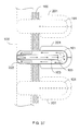
- FIG. 17 is a schematic structural view of the present invention showing the front portion of the external tube (101) being formed with a manifold structure for being installed with plural electric energy application device assemblies (108) which sharing the mid tube body and the distal tube body of the external tube (101).
- the main configuration includes the mentioned external tube (101), the inner tube (103), the fluid pump (105), wherein the front portion of the external tube (101) is formed with a manifold structure allowing plural electric energy application device assemblies (108) to be installed thereon, and formed with a common mid tube body and distal tube body of the external tube (101), and same or different electric energy application device assemblies (108) are respectively installed on the manifold formed on the front portion of the external tube (101), and correspondingly installed with an inner tube (103) in the external tube (101);
- the heat transfer fluid pumped by the fluid pump (105) passes the heat transfer fluid path on the surface or in the interior of the individual electric energy application device assembly (108) or the heat dissipater (104) thereof, and passes the interior of the external tube (101), so through the heat transfer fluid passing the outer surface of the electric energy application device assembly (108) or the heat dissipater thereof, and/or the exposed portion of the external tube (101), temperature equalizing operation is enabled to be performed with the external gaseous
- the structure formed through the external tube (101) and the inner tube (103) includes one or more than one of followings:
- FIG. 18 is a first schematic view showing the tube structure of the present invention.
- FIG. 19 is a cross sectional view of FIG 18 taken along X-X.
- the main configuration is that the external tube (101) and the inner tube (103) are arranged in coaxial or in a substantially parallel manner, the space defined by the periphery of the inner tube (103) and between the external tube (101) and the inner tube (103) is served to allow the heat transfer fluid to pass, the inner tube (103) installed in the external tube (101) is shorter than the external tube (101), a length differentiation is formed between the distal end thereof and the sealed part at the distal portion of the external tube (101) and a supporter (1033) is provided for fastening, thereby forming the space allowing the heat transfer fluid to pass.
- FIG. 20 is a second schematic view showing the tube structure of the present invention.
- FIG. 21 is a cross sectional view of FIG 20 taken along X-X.
- the main configuration is that the external tube (101) and the inner tube (103) are installed in parallel, the distal end of the inner tube (103) inside the external tube (101) is combined with the sealed part at the bottom of distal portion of the external tube (101), and the distal end of the inner tube (103) or a transversal hole (1031) or a notch (1032) penetrating the inner tube at the distal portion of the inner tube (103) are forming the space allowing the heat transfer fluid to pass.
- FIG. 22 is the third schematic view showing the tube structure of the present invention.
- FIG. 23 is a cross sectional view of FIG. 22 taken along X-X.
- the main configuration is that the external tube (101) and the inner tube (103) are eccentrically arranged, the distal end of the inner tube (103) installed inside the external tube (101) is shorter, a length differentiation is formed between the distal end thereof and the sealed part at the bottom of the distal portion of the external tube (101) thereby forming a space allowing the heat transfer fluid to pass.
- FIG. 24 is a fourth schematic view showing the tube structure of the present invention.
- FIG. 25 is a cross sectional view of FIG. 24 taken along X-X.
- the main configuration is that the external tube (101) and two or more than two of the inner tubes (103) are installed in parallel, the distal portion of the inner tube (103) installed inside the external tube (101) is shorter, a length differentiation is formed between the distal portion thereof and the sealed part at the bottom of the distal portion of the external tube (101) thereby forming a space allowing the heat transfer fluid to pass.
- FIG. 26 is a fifth schematic view showing the tube structure of the present invention.
- FIG. 27 is a cross sectional view of FIG 26 taken along X-X.
- the main configuration is that the external tube (101) and the inner tube (103) are arranged in coaxial or in a substantially parallel manner, the space defined by the periphery of the inner tube (103) and between the external tube (101) and the inner tube (103) is served to allow the heat transfer fluid to pass, the inner tube (103) installed inside the external tube (101) is shorter than the external tube (101), a length differentiation is formed between the distal portion thereof and the sealed part at the bottom of the distal portion of the external tube (101) thereby forming a space allowing the heat transfer fluid to pass, a spiral flow guiding structure (2003) is further installed between the external tube (101) and the inner tube (103) thereby increasing the length of the heat transfer fluid path formed between the external tube (101) and the inner tube (103).
- FIG. 28 is a schematic structural view of the present invention showing a heat transfer fluid path allowing the gaseous or liquid heat transfer fluid to pass being formed through the space defined by the heat dissipater (104) of the electric energy application device assembly (108) and the housing (106) and the heat transfer fluid path (1041) of the heat dissipater (104).
- the main configuration is that a heat transfer fluid path allowing the gaseous or liquid heat transfer fluid to pass is formed through the space defined by the heat dissipater (104) of the electric energy application device assembly (108) and the housing (106) and the heat transfer fluid path (1041) of the heat dissipater (104).
- FIG. 29 is a schematic structural view of the present invention showing a heat transfer fluid path allowing the gaseous or liquid heat transfer fluid to pass being formed through at least two heat transfer fluid paths (1041) of the heat dissipater (104) installed in the electric energy application device assembly (108) being serially connected with a U-shaped connection tube (1042).
- the main configuration is that at least two heat transfer fluid paths (1041) of the heat dissipater (104) installed in the electric energy application device assembly (108) are connected with a U-shaped connection tube (1042) in serial, so as to constitute a heat transfer fluid path allowing the gaseous or liquid heat transfer fluid to pass.
- FIG. 30 is a schematic structural view of the present invention showing a heat transfer fluid path allowing the gaseous or liquid heat transfer fluid to pass being formed through the space defined by the electric energy application device assembly (108) and the housing (106) and the heat transfer fluid path (1081) provided by the electric energy application device assembly (108).
- the main configuration is that through the space defined by the electric energy application device assembly (108) and the housing (106) and the heat transfer fluid path (1081) provide by the electric energy application device assembly (108), a heat transfer fluid path allowing the gaseous or liquid heat transfer fluid to pass is formed.
- FIG. 31 is a schematic structural view of the present invention showing a heat transfer fluid path allowing the gaseous or liquid heat transfer fluid to pass being formed through at least two heat transfer fluid paths (1081) of the electric energy application device assembly (108) being serially connected with a U-shaped connection tube (1042).
- the main configuration is that at least two of the heat transfer fluid paths (1081) provided by the electric energy application device assembly (108) are connected in serial with a U-shaped connection tube (1042), thereby to constitute a heat transfer fluid path allowing the gaseous or liquid heat transfer fluid to pass.
- FIG. 32 is a schematic structural view of the present invention showing a heat transfer fluid path allowing the gaseous or liquid heat transfer fluid to pass being formed through a U-shaped connection tube (1042) being connected between at least one heat transfer fluid path (1081) of the electric energy application device assembly (108) and at least one heat transfer fluid path (1041) of the heat dissipater (104) thereof.
- the main configuration is that at least one heat transfer fluid path (1081) provided by the electric energy application device assembly (108) and at least one heat transfer fluid path (1041) provided by the heat dissipater (104) thereof are connected in serial with a U-shaped connection tube (1042), thereby to constitute a heat transfer fluid path allowing the gaseous or liquid heat transfer fluid to pass.
- the applicable fields of the heat-dissipating structure having suspended external tube and internally recycling heat transfer fluid and application apparatus are very flexible, wherein the heat-dissipating structure having internally recycling heat transfer fluid flowing in tubes and installed in the electric energy application device assembly (108) can be one or more than one, the exposed portion of the external tube (101) enables the temperature equalizing operation to be performed with the external gaseous environment or the liquid or solid environment manually installed but not disposed in the stratum or liquid of the shallow ground natural thermal energy body, the surface of the external tube (101) can be optionally installed with external heat guiding plates (201), the portion of the surface of the external tube (101) which is disposed in the interior of the electric energy application device assembly (108) can be optionally installed with inner heat guiding plates (203), and the installation and operating direction are not limited, illustrations are provided as followings:
- the fastening means can be the conventional means such as utilizing a support rod or chain or hook or a suspending hook device for fastening a standing lamp or ceiling lamp or a standing fan or ceiling fan, thereby being able to be vertically installed at the top of a building or the top of a structural unit having internal space or a moveable object.
- the installation means disclosed in the embodiment shown in FIG 33 and FIG. 34 includes one or more than one of following installation means:
- the fastening means can be the conventional means such as horizontally installing a window-type air conditioner on a wall or the window of a freezing cabinet of a transportation vehicle, thereby being able to be horizontally installed on the lateral side of a building or the lateral side of a structural unit or a moveable object.
- FIG. 36 is a schematic structural diagram showing single electric energy application device assembly (108) being vertically installed with plural heat-dissipating structures having internally recycling heat transfer fluid flowing in tubes.
- the main configuration is that single electric energy application device assembly (108) is vertically installed with two or more than two of the heat-dissipating structures having internally recycling heat transfer fluid flowing in tubes
- the fastening means can be the conventional means such as utilizing a support rod or chain or hook or a suspending hook device for fastening a standing lamp or ceiling lamp or a standing fan or ceiling fan, thereby being able to be vertically installed at the top of a building or the top of a structural unit having internal space or a moveable object.
- FIG. 37 is a schematic structural view of one embodiment showing single electric energy application device assembly (108) being installed with plural heat-dissipating structures having internally recycling heat transfer fluid flowing in tubes for being horizontally and penetratingly installed on a wall.
- the main configuration is that single electric energy application device assembly (108) is horizontally installed with two or more than two of the heat-dissipating structures having internally recycling heat transfer fluid flowing in tubes
- the fastening means can be the conventional means such as horizontally installing a window-type air conditioner on a wall or the window of a freezing cabinet of a transportation vehicle, thereby being able to be horizontally installed on the lateral side of a building or the lateral side of a structural unit or a moveable object.
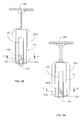
- FIG. 38 is a schematic structural view of the first embodiment showing the heat dissipater of the present application being installed with a conical flow guiding body (1040) having thermal conductivity and being installed in a downward configuration.
- the internal of the heat-dissipating structure of the present invention is configured as a conical flow guiding body (1040) having thermal conductivity, so as to reduce the flowing resistance of the internal fluid, and the top thereof is suspended through a hanging chain.
- FIG. 39 is a schematic structural view of the second embodiment showing the heat dissipater of the present application being installed with a conical flow guiding body (1040) having thermal conductivity and being installed in a downward configuration.
- the internal of the heat-dissipating structure of the present invention is configured as a conical flow guiding body (1040) having thermal conductivity, so as to reduce the flowing resistance of the internal fluid, and the top thereof is suspended through a hanging tube and a brocket.
- FIG. 40 is a schematic structural view of the third embodiment showing the heat dissipater of the present application being installed with a conical flow guiding body (1040) having thermal conductivity and being installed in a downward configuration.
- the internal of the heat-dissipating structure of the present invention is configured as a conical flow guiding body (1040) having thermal conductivity, so as to reduce the flowing resistance of the internal fluid, and the top thereof is fixed suspended through having an extended external tube to be combined with a fixed holder (555) with connecting and fastening function and heat-dissipating property.
- FIG. 41 is a bottom side view of FIG. 38, FIG. 39 and FIG. 40 .
- FIG. 42 is a cross sectional view of FIG. 38, FIG. 39 and FIG. 40 taken along A-A.
- the heat-dissipating structure having suspended external tube and internally recycling heat transfer fluid and application apparatus can not only be applied for being combined and installed as what the embodiments has disclosed above, but also can be applied in the electric energy application device assembly (108) composed of various lamps and/or the heat discharging device used for discharging heat to the exterior or an electric heater or air warmer or heat pump having the heat discharging device, and/or the cold discharging device used for discharging cold to the exterior or an air conditioner having the cold discharging device, the theory and structure of installing the external tube with a suspending manner and the heat-dissipating structure of the internally recycling heat transfer fluid are the same as the disclosed embodiments therefore no further illustration is provided.
Landscapes
- Engineering & Computer Science (AREA)
- General Engineering & Computer Science (AREA)
- Physics & Mathematics (AREA)
- Thermal Sciences (AREA)
- Mechanical Engineering (AREA)
- Sustainable Development (AREA)
- Life Sciences & Earth Sciences (AREA)
- Cooling Or The Like Of Electrical Apparatus (AREA)
- Filling Or Discharging Of Gas Storage Vessels (AREA)
- Arrangement Of Elements, Cooling, Sealing, Or The Like Of Lighting Devices (AREA)
- Motor Or Generator Cooling System (AREA)
- Photovoltaic Devices (AREA)
- External Artificial Organs (AREA)
Abstract
Description
- The present invention is to provide one or more than one of external tubes (101) suspendedly installed and capable of performing temperature equalizing operation with an external gaseous environment or a liquid or solid environment which is manually installed but not disposed in the stratum or liquid of the shallow ground natural thermal energy body, the interior of the external tube (101) is provided with an inner tube (103), the inner diameter of the external tube (101) is larger than the outer diameter of the inner tube (103), the space defined by the diameter differentiation is formed as a heat transfer fluid path, the distal end of the external tube (101) is sealed, the distal end of the inner tube (103) is shorter than the distal end of the external tube (101) or preformed with fluid holes, the distal ends of both tubes are formed with a flow returning segment allowing the heat transfer fluid to be returned;
- The front tube port of the external tube (101) and the front tube port of the inner tube (103) allow the heat transfer fluid passing an electric energy application device assembly (108) and/or a heat dissipater thereof to be transferred, wherein one of the tube ports allows the heat transfer fluid to be transferred for passing the electric energy application device assembly (108) and/or the heat dissipater thereof, and the other tube port allows the heat transfer fluid which already passed the electric energy application device assembly (108) and/or the heat dissipater thereof to be returned;
- When two or more than two of the external tubes (101) are installed and individually provided with the inner tube (103) therein, the fluid paths formed by the individual external tube (101) and the inner tube (103) thereof can be connected in serial or in parallel and leaded to a common electric energy application device assembly (108), or respectively leaded to a corresponding electric energy application device assembly (108), and can be designed to share a common fluid pump (105) or respectively installed with a fluid pump (105);
- One or more than one of fluid pumps (105) are serially installed on the closed recycling heat transfer fluid path, the flowing direction thereof can be selected from one flowing direction or two flowing directions enabled to be switched or periodically changed;
- The gaseous or liquid heat transfer fluid pumped by the fluid pump (105) passes the external tube (101) of the closed recycling heat transfer fluid path and the exposed portion of the relevant structure, thereby enabling to perform temperature equalizing operation with the external gaseous environment or the liquid or solid environment manually installed but not disposed in the stratum or liquid of the shallow ground natural thermal energy body;
- When the external tube (101) is formed as a vertically upward or obliquely upward or spirally upward structure, the fluid can take advantage of the physical effect of hot ascending/cold descending to allow the fluid having higher temperature to ascend in the inner tube and the fluid having lower temperature to descend in the interior of the external tube, thereby forming a flow recycling, and/or the fluid pump (105) can be further installed.
- A conventional electric energy application device assembly, e.g. an illumination device utilizing electric energy being converted into photo energy, an illumination device adopting LED, a photovoltaic, a wind power generator, a transformer or a motor, generates thermal energy while being operated, so over-heating prevention or anti-freezing for the mentioned assembly is very important.
- The present invention is to provide one or more than one of external tubes (101) suspendedly installed and capable of performing temperature equalizing operation with an external gaseous environment or a liquid or solid environment which is manually installed but not disposed in the stratum or liquid of the shallow ground natural thermal energy body, the interior of the external tube (101) is provided with an inner tube (103), the inner diameter of the external tube (101) is larger than the outer diameter of the inner tube (103), the space defined by the diameter differentiation is formed as a heat transfer fluid path, the distal end of the external tube (101) is sealed, the distal end of the inner tube (103) is shorter than the distal end of the external tube (101) or preformed with fluid holes, the distal ends of both tubes are formed with a flow returning segment allowing the heat transfer fluid to be returned;
- The front tube port of the external tube (101) and the front tube port of the inner tube (103) allow the heat transfer fluid passing an electric energy application device assembly (108) and/or a heat dissipater thereof to be transferred, wherein one of the tube ports allows the heat transfer fluid to be transferred for passing the electric energy application device assembly (108) and/or the heat dissipater thereof, and the other tube port allows the heat transfer fluid which already passed the electric energy application device assembly (108) and/or the heat dissipater thereof to be returned;
- When two or more than two of the external tubes (101) are installed and individually provided with the inner tube (103) therein, the fluid paths formed by the individual external tube (101) and the inner tube (103) thereof can be connected in serial or in parallel and leaded to a common electric energy application device assembly (108), or respectively leaded to a corresponding electric energy application device assembly (108), and can be designed to share a common fluid pump (105) or respectively installed with a fluid pump (105);
- One or more than one of fluid pumps (105) are serially installed on the closed recycling heat transfer fluid path, the flowing direction thereof can be selected from one flowing direction or two flowing directions enabled to be switched or periodically changed;
- The structure of the heat transfer fluid path formed between the mentioned electric energy application device assembly (108) and/or the heat dissipater thereof and the external tube (101) and the inner tube (103) includes one or more than one of followings:
- (a) the interior of the electric energy application device assembly (108) is formed with one or more than one of heat transfer fluid paths connected in serial or in parallel to pass through, the fluid inlet port and the fluid outlet port are respectively communicated with the tube port of the external tube (101) and the tube port of the inner tube (103);
- (b) the heat dissipater installed in the electric energy application device assembly (108) is formed with one or more than one of heat transfer fluid paths connected in parallel to pass through, the fluid inlet port and the fluid outlet port are respectively communicated with the tube port of the external tube (101) and the tube port of the inner tube (103);
- (c) one or more than one of heat transfer fluid paths formed in the interior of the electric energy application device assembly (108) are connected in serial or in parallel with the heat transfer fluid paths formed in the heat dissipater, the fluid inlet port and the fluid outlet port are respectively communicated with the tube port of the external tube (101) and the tube port of the inner tube (103);
- (d) the electric energy application device assembly (108) is formed with two or more than two of heat transfer fluid paths connected through external tubes so as to form the fluid inlet port and the fluid outlet port respectively communicated with the tube port of the external tube (101) and the tube port of the inner tube (103), or the interior thereof is bent to the U-like shape or L-like shape, and the fluid inlet port and the flow outlet port at the same or different sides are respectively communicated with the tube port of the external tube (101) and the tube port of the inner tube (103);
- (e) the exterior of the electric energy application device assembly (108) is installed with a sealed housing, thereby forming a space between the above two for allowing the heat transfer fluid to pass, the electric energy application device assembly (108) is formed with one or more than one of heat transfer fluid paths connected in serial or in parallel, one end thereof is formed with a heat transfer fluid inlet/outlet port which is leaded to the tube port of the inner tube (103), the tube port at the other end is leaded to the space formed between the housing and the electric energy application device assembly (108), and a heat transfer fluid connection port is formed on the sealed housing for being communicated with the tube port of the external tube (101);
- (f) a sealed space allowing the heat transfer fluid to pass is formed between the electric energy application device assembly (108) and the heat dissipater thereof, and the exterior and the installed housing, the electric energy application device assembly (108) and/or the heat dissipater thereof is formed with one or more than one of heat transfer fluid paths connected in serial or in parallel, one end thereof is formed with a heat transfer fluid inlet/outlet port which is leaded to the tube port of the inner tube (103), the tube port at the other end is leaded to the space formed between the housing and the electric energy application device assembly (108) and/or the heat dissipater thereof, a heat transfer fluid inlet/outlet port is formed on the sealed housing for being communicated with the tube port of the external tube (101);
- (g) a sealed housing is jointly formed through the exterior of the electric energy application device assembly (108) and/or the heat dissipater thereof and the matched housing, the interior of the electric energy application device assembly (108) and/or the heat dissipater thereof and the matched housing is formed with a space allowing the heat transfer fluid to pass and leaded to the tube port of the external tube (101), the electric energy application device assembly (108) and/or the heat dissipater thereof is formed with one or more than one of heat transfer fluid paths connected in serial or in parallel, one end thereof is formed with a heat transfer fluid connection port which is leaded to the tube port of the inner tube (103), the tube port at the other end is leaded to the space formed between the housing and the electric energy application device assembly (108) and/or the heat dissipater thereof, a heat transfer fluid connection port is formed on the sealed housing for being communicated with the tube port of the external tube (101);
- The gaseous or liquid heat transfer fluid pumped by the fluid pump (105) passes the external tube (101) of the closed recycling heat transfer fluid path and the exposed portion of the relevant structure, thereby enabling to perform temperature equalizing operation with the external gaseous environment or the liquid or solid environment manually installed but not disposed in the stratum or liquid of the shallow ground natural thermal energy body;
- When the external tube (101) is formed as a vertically upward or obliquely upward or spirally upward structure, the fluid can take advantage of the physical effect of hot ascending/cold descending to allow the fluid having higher temperature to ascend in the inner tube and the fluid having lower temperature to descend in the interior of the external tube, thereby forming a flow recycling, and/or the fluid pump (105) can be further installed;
- The mentioned electric energy application device assembly (108) includes an illumination device utilizing electric energy being converted into photo energy, e.g. an illumination device adopting LED and/or a photovoltaic, e.g. a solar panel and/or a wind power generator and/or a transformer and/or an electric driven motor, and/or a heat discharging device used for discharging heat to the exterior or an electric heater or air warmer or heat pump having the heat discharging device, and/or a cold discharging device used for discharging cold to the exterior or an air conditioner having the cold discharging device, and peripheral devices, drive control circuits devices, overload protecting devices and/or temperature protection devices are optionally installed according to actual needs for assisting the operation of the electric energy application device assembly (108).
- According to another aspect of the invention, a heat dissipating structure comprises: a suspended external tube (101); an inner tube (103) disposed inside the external tube (101) so as to form a partition space between the inner diameter of the external tube (101) and the outer diameter of the inner tube (103) so that the inner tube (103) and the partition space form a closed loop fluid path; and the front tube of the external tube is served to be installed with an electric energy application device assembly (108) installed at the front of the external tube (101); wherein the fluid can take advantage of the physical effect of hot ascending/cold descending to allow the fluid having higher temperature to ascend in the inner tube and the fluid having lower temperature to descend in the interior of the external tube, thereby forming a flow recycling, and/or a fluid pump (105) can be further installed. According to one embodiment, the electric energy application device assembly (108) includes an electric illuminating device (109).
-
-
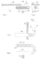
FIG. 1 is a schematic view showing the main structure of the present invention. -
FIG. 2 is a cross section view ofFIG. 1 taken along X-X. -
FIG. 3 is a schematic structural view illustrating the mechanical structure between the external tube (101) and the electric energy application device assembly (108) being formed in a bending structure with vertical angle or certain non-vertical angle. -
FIG. 4 is a schematic structural view illustrating the mechanical structure between the external tube (101) and the electric energy application device assembly (108) being formed in a U-shaped structure. -
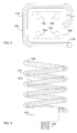
FIG. 5 is a schematic structural view illustrating the mechanical structure between the external tube (101) and the electric energy application device assembly (108) being formed in a swirl structure with one or more loops. -
FIG. 6 is a schematic structural view illustrating the mechanical structure between the external tube (101) and the electric energy application device assembly (108) being formed in a spiral structure. -
FIG. 7 is a schematic structural view illustrating the mechanical structure between the external tube (101) and the electric energy application device assembly (108) being formed in a wavelike bending structure oriented towards up/down or left/right. -
FIG. 8 is a schematic structural view showing theFIG. 1 being provided with a housing. -
FIG. 9 is a cross section view ofFIG. 8 taken along X-X. -
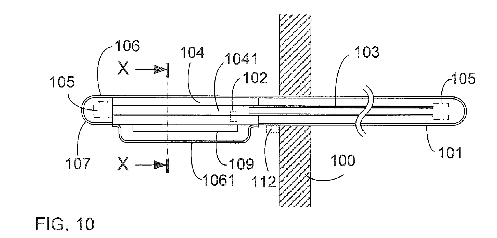
FIG. 10 is a schematic structural view of the present invention illustrating the electric illuminating device (109) being adopted as the electric energy application device assembly (108) and/or the heat dissipater (104) thereof. -
FIG. 11 is a cross sectional view ofFIG. 10 taken along X-X. -
FIG. 12 is a schematic structural view of the present invention illustrating the photovoltaic (110) being adopted as the electric energy application device assembly (108). -
FIG. 13 is a cross sectional view ofFIG 12 taken along X-X. -
FIG. 14 is a schematic structural view of the present invention illustrating the wind power generating device (111) being adopted as the electric energy application device assembly (108). -
FIG. 15 is a schematic structural view of the present invention illustrating the transformer (444) being adopted as the electric energy application device assembly (108). -
FIG. 16 is a schematic structural view of the present invention illustrating the motor (333) driven by electric energy being adopted as the electric energy application device assembly (108). -
FIG. 17 is a schematic structural view of the present invention showing the front portion of the external tube (101) being formed with a manifold structure for being installed with plural electric energy application device assemblies (108) which sharing the mid tube body and the distal tube body of the external tube (101). -
FIG. 18 is a first schematic view showing the tube structure of the present invention. -
FIG. 19 is a cross sectional view ofFIG 18 taken along X-X. -
FIG. 20 is a second schematic view showing the tube structure of the present invention. -
FIG. 21 is a cross sectional view ofFIG 20 taken along X-X. -
FIG. 22 is the third schematic view showing the tube structure of the present invention. -
FIG. 23 is a cross sectional view ofFIG. 22 taken along X-X. -
FIG. 24 is a fourth schematic view showing the tube structure of the present invention. -
FIG. 25 is a cross sectional view ofFIG 24 taken along X-X. -
FIG. 26 is a fifth schematic view showing the tube structure of the present invention. -
FIG. 27 is a cross sectional view ofFIG 26 taken along X-X. -
FIG. 28 is a schematic structural view of the present invention showing a heat transfer fluid path allowing the gaseous or liquid heat transfer fluid to pass being formed through the space defined by the heat dissipater (104) of the electric energy application device assembly (108) and the housing (106) and the heat transfer fluid path (1041) of the heat dissipater (104). -
FIG. 29 is a schematic structural view of the present invention showing a heat transfer fluid path allowing the gaseous or liquid heat transfer fluid to pass being formed through at least two heat transfer fluid paths (1041) of the heat dissipater (104) installed in the electric energy application device assembly (108) being serially connected with a U-shaped connection tube (1042). -
FIG. 30 is a schematic structural view of the present invention showing a heat transfer fluid path allowing the gaseous or liquid heat transfer fluid to pass being formed through the space defined by the electric energy application device assembly (108) and the housing (106) and the heat transfer fluid path (1081) provided by the electric energy application device assembly (108). -
FIG. 31 is a schematic structural view of the present invention showing a heat transfer fluid path allowing the gaseous or liquid heat transfer fluid to pass being formed through at least two heat transfer fluid paths (1081) of the electric energy application device assembly (108) being serially connected with a U-shaped connection tube (1042). -
FIG. 32 is a schematic structural view of the present invention showing a heat transfer fluid path allowing the gaseous or liquid heat transfer fluid to pass being formed through a U-shaped connection tube (1042) being connected between at least one heat transfer fluid path (1081) of the electric energy application device assembly (108) and at least one heat transfer fluid path (1041) of the heat dissipater (104) thereof. -
FIG. 33 is a schematic view showing the main structure being vertically installed according to one embodiment of the present invention. -
FIG. 34 is a cross sectional view ofFIG 33 taken along X-X. -
FIG. 35 is a schematic structural diagram of one embodiment showing the present invention being horizontally and penetratingly installed on a wall. -
FIG. 36 is a schematic structural diagram showing single electric energy application device assembly (108) being vertically installed with plural heat-dissipating structures having internally recycling heat transfer fluid flowing in tubes. -
FIG. 37 is a schematic structural view of one embodiment showing single electric energy application device assembly (108) being installed with plural heat-dissipating structures having internally recycling heat transfer fluid flowing in tubes for being horizontally and penetratingly installed on a wall. -
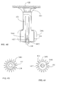
FIG. 38 is a schematic structural view of the first embodiment showing the heat dissipater of the present application being installed with a conical flow guiding body (1040) having thermal conductivity and being installed in a downward configuration. -
FIG. 39 is a schematic structural view of the second embodiment showing the heat dissipater of the present application being installed with a conical flow guiding body (1040) having thermal conductivity and being installed in a downward configuration. -
FIG. 40 is a schematic structural view of the third embodiment showing the heat dissipater of the present application being installed with a conical flow guiding body (1040) having thermal conductivity and being installed in a downward configuration. -
FIG. 41 is a bottom side view ofFIG. 38, FIG. 39 andFIG. 40 . -
FIG. 42 is a cross sectional view ofFIG 38, FIG. 39 andFIG. 40 taken along A-A. -
- 100: Fastening and supporting structural member
- 101: External tube
- 102: Temperature protecting device
- 103: Inner tube
- 1031: Transversal hole
- 1032: Notch
- 1033: Supporter
- 104: Heat dissipater
- 1040: Conical flow guiding body
- 1041: Heat transfer fluid path of heat dissipater
- 1042: U-shaped connection tube
- 105: Fluid pump
- 106: Housing
- 1061: Light-pervious member
- 107: Heat transfer fluid path
- 108: Electric energy application device assembly
- 1081: Heat transfer fluid path
- 109: Electric illuminating device
- 110: Photovoltaic
- 111: Wind power generating device
- 112: Drive control circuit device
- 201: External heat guiding plate
- 203: Inner heat guiding plate
- 222: Wind power generator
- 2001: Heat transfer fin
- 2003: Spiral flow guiding structure
- 333: Motor
- 334: Motor driving load
- 444: Transformer
- 445: Transformer support rack
- 555: Fixed holder
- A conventional electric energy application device assembly, e.g. an illumination device utilizing electric energy being converted into photo energy, an illumination device adopting LED, a photovoltaic, a wind power generator, a transformer or a motor, generates thermal energy while being operated, so over-heating prevention or anti-freezing for the mentioned assembly is very important;
- The present invention is to provide one or more than one of external tubes (101) suspendedly installed and capable of performing temperature equalizing operation with an external gaseous environment or a liquid or solid environment which is manually installed but not disposed in the stratum or liquid of the shallow ground natural thermal energy body, the interior of the external tube (101) is provided with an inner tube (103), the inner diameter of the external tube (101) is larger than the outer diameter of the inner tube (103), the space defined by the diameter differentiation is formed as a heat transfer fluid path, the distal end of the external tube (101) is sealed, the distal end of the inner tube (103) is shorter than the distal end of the external tube (101) or preformed with fluid holes, the distal ends of both tubes are formed with a flow returning segment allowing the heat transfer fluid to be returned;
- The front tube port of the external tube (101) and the front tube port of the inner tube (103) allow the heat transfer fluid passing an electric energy application device assembly (108) and/or a heat dissipater thereof to be transferred, wherein one of the tube ports allows the heat transfer fluid to be transferred for passing the electric energy application device assembly (108) and/or the heat dissipater thereof, and the other tube port allows the heat transfer fluid which already passed the electric energy application device assembly (108) and/or the heat dissipater thereof to be returned;
- When two or more than two of the external tubes (101) are installed and individually provided with the inner tube (103) therein, the fluid paths formed by the individual external tube (101) and the inner tube (103) thereof can be connected in serial or in parallel and leaded to a common electric energy application device assembly (108), or respectively leaded to a corresponding electric energy application device assembly (108), and can be designed to share a common fluid pump (105) or respectively installed with a fluid pump (105);
- One or more than one of fluid pumps (105) are serially installed on the closed recycling heat transfer fluid path, the flowing direction thereof can be selected from one flowing direction or two flowing directions enabled to be switched or periodically changed;
- The structure of the heat transfer fluid path formed between the mentioned electric energy application device assembly (108) and/or the heat dissipater thereof and the external tube (101) and the inner tube (103) includes one or more than one of followings:
- (a) the interior of the electric energy application device assembly (108) is formed with one or more than one of heat transfer fluid paths connected in serial or in parallel to pass through, the fluid inlet port and the fluid outlet port are respectively communicated with the tube port of the external tube (101) and the tube port of the inner tube (103);
- (b) the heat dissipater installed in the electric energy application device assembly (108) is formed with one or more than one of heat transfer fluid paths connected in parallel to pass through, the fluid inlet port and the fluid outlet port are respectively communicated with the tube port of the external tube (101) and the tube port of the inner tube (103);
- (c) one or more than one of heat transfer fluid paths formed in the interior of the electric energy application device assembly (108) are connected in serial or in parallel with the heat transfer fluid paths formed in the heat dissipater, the fluid inlet port and the fluid outlet port are respectively communicated with the tube port of the external tube (101) and the tube port of the inner tube (103);
- (d) the electric energy application device assembly (108) is formed with two or more than two of heat transfer fluid paths connected through external tubes so as to form the fluid inlet port and the fluid outlet port respectively communicated with the tube port of the external tube (101) and the tube port of the inner tube (103), or the interior thereof is bent to the U-like shape or L-like shape, and the fluid inlet port and the flow outlet port at the same or different sides are respectively communicated with the tube port of the external tube (101) and the tube port of the inner tube (103);
- (e) the exterior of the electric energy application device assembly (108) is installed with a sealed housing, thereby forming a space between the above two for allowing the heat transfer fluid to pass, the electric energy application device assembly (108) is formed with one or more than one of heat transfer fluid paths connected in serial or in parallel, one end thereof is formed with a heat transfer fluid inlet/outlet port which is leaded to the tube port of the inner tube (103), the tube port at the other end is leaded to the space formed between the housing and the electric energy application device assembly (108), and a heat transfer fluid connection port is formed on the sealed housing for being communicated with the tube port of the external tube (101);
- (f) a sealed space allowing the heat transfer fluid to pass is formed between the electric energy application device assembly (108) and the heat dissipater thereof, and the exterior and the installed housing, the electric energy application device assembly (108) and/or the heat dissipater thereof is formed with one or more than one of heat transfer fluid paths connected in serial or in parallel, one end thereof is formed with a heat transfer fluid inlet/outlet port which is leaded to the tube port of the inner tube (103), the tube port at the other end is leaded to the space formed between the housing and the electric energy application device assembly (108) and/or the heat dissipater thereof, a heat transfer fluid inlet/outlet port is formed on the sealed housing for being communicated with the tube port of the external tube (101);
- (g) a sealed housing is jointly formed through the exterior of the electric energy application device assembly (108) and/or the heat dissipater thereof and the matched housing, the interior of the electric energy application device assembly (108) and/or the heat dissipater thereof and the matched housing is formed with a space allowing the heat transfer fluid to pass and leaded to the tube port of the external tube (101), the electric energy application device assembly (108) and/or the heat dissipater thereof is formed with one or more than one of heat transfer fluid paths connected in serial or in parallel, one end thereof is formed with a heat transfer fluid connection port which is leaded to the tube port of the inner tube (103), the tube port at the other end is leaded to the space formed between the housing and the electric energy application device assembly (108) and/or the heat dissipater thereof, a heat transfer fluid connection port is formed on the sealed housing for being communicated with the tube port of the external tube (101);
- The gaseous or liquid heat transfer fluid pumped by the fluid pump (105) passes the external tube (101) of the closed recycling heat transfer fluid path and the exposed portion of the relevant structure, thereby enabling to perform temperature equalizing operation with the external gaseous environment or the liquid or solid environment manually installed but not disposed in the stratum or liquid of the shallow ground natural thermal energy body;
- When the external tube (101) is formed as a vertically upward or obliquely upward or spirally upward structure, the fluid can take advantage of the physical effect of hot ascending/cold descending to allow the fluid having higher temperature to ascend in the inner tube and the fluid having lower temperature to descend in the interior of the external tube, thereby forming a flow recycling, and/or the fluid pump (105) can be further installed;
- The mentioned electric energy application device assembly (108) includes an illumination device utilizing electric energy being converted into photo energy, e.g. an illumination device adopting LED and/or a photovoltaic, e.g. a solar panel and/or a wind power generator and/or a transformer and/or an electric driven motor, and/or a heat discharging device used for discharging heat to the exterior or an electric heater or air warmer or heat pump having the heat discharging device, and/or a cold discharging device used for discharging cold to the exterior or an air conditioner having the cold discharging device, and peripheral devices, drive control circuits devices, overload protecting devices and/or temperature protection devices are optionally installed according to actual needs for assisting the operation of the electric energy application device assembly (108);
- Main components of the heat-dissipating structure having suspended external tube and internally recycling heat transfer fluid and application apparatus are illustrated by following embodiment:
-
FIG. 1 is a schematic view showing the main structure of the present invention. -
FIG. 2 is a cross section view ofFIG. 1 taken along X-X. - As shown in
FIG. 1 and FIG. 2 , mainly consists: - -- external tube (101): constituted by one or more than one of hollow tube members with materials having mechanical strength, the tube body is divided into a front tube body, a mid tube body and a distal tube body, wherein:
- The front tube body is mainly served to be installed with the electric energy application device assembly (108);
- The mid tube body is served to provide a support function and to transfer the thermal energy between the interior and the exterior of the tube;
- The distal tube body is served to perform temperature equalizing operation with the external gaseous environment or the liquid or solid environment manually installed but not disposed in the stratum or liquid of the shallow ground natural thermal energy body;
- The external tube (101) includes being formed in round shape or other geometric shapes, and being made of a material having mechanical strength and better heat conductivity or a material having heat insulation property; the mentioned external tube (101) can be optionally installed with heat transfer fins (2001) at the exterior thereof according to actual needs;
- The mentioned mechanical structure between the external tube (101) and the electric energy application device assembly (108) includes one or more than one of geometrically extended structures in one dimension or two dimensions or three dimensions; as followings
- (a) formed in the linear structure (as shown in
FIG. 1 ); - (b) formed in the bending structure with vertical angle or certain non-vertical angle (as shown in
FIG. 3 ); - (c) formed in the U-shaped structure (as shown in
FIG. 4 ); - (d) formed in the swirl structure with one or more loops (as shown in
FIG. 5 ); - (e) formed in the spiral structure (as shown in
FIG. 6 ); - (f) formed in the wavelike bending structure oriented towards up/down or left/right (as shown in
FIG. 7 ); - -- inner tube (103): constituted by a tube member having an outer diameter smaller than the inner diameter of the external tube (101) and made of a hard material, e.g. metal material, or a flexible material or a soft material, e.g. plastic, or a fabric or other materials having similar properties, the inner tube (103) is formed in a linear or bended or curved shaped or can be freely deformed if being made of the flexible material or the soft material thereby being enabled to be installed in the external tube (101) without affecting the smoothness of the heat transfer fluid path, the front portion thereof is leaded to the heat transfer fluid path of the electric energy application device assembly (108) or the heat dissipater thereof installed at the front portion of the external tube (101), the distal portion thereof is leaded to the mid portion or extended to the distal portion of the external tube (101), a diameter differentiation is formed between the outer diameter of the inner tube (103) and the inner diameter of the external tube (101) thereby forming a reversed space which can be served as the heat transfer fluid path, so the fluid path allowing the heat transfer fluid to pass is formed through the inner tube and two tube ports at two ends of the inner tube and the reserved space formed between the outer diameter of the inner tube and the inner diameter of the outer tube, and selected locations defined on the mentioned fluid path can be serially installed with one or more than one of fluid pumps (105), the space defined between the front portion of the inner tube (103) and the front portion of the external tube (101) is served to allow the electric energy application device assembly (108) to be installed;
- The inner tube (103) includes being formed in round shape or other geometric shapes, and being made of (a) a hard material or flexible material or soft material having heat insulation property, or (b) a hard material or flexible material or soft material having better heat conductivity, and the exterior of the tube member is provided with a heat insulation material, or (c) a hard material or flexible material or soft material having better heat conductivity, and the interior of the tube member is provided with a heat insulation material, or (d) a hard material or flexible material or soft material having better heat conductivity;
- When two or more than two of the external tubes (101) are installed and individually provided with the inner tube (103) therein, the fluid paths formed by the individual external tube (101) and the inner tube (103) thereof can be connected in serial or in parallel and leaded to a common electric energy application device assembly (108), or respectively leaded to a corresponding electric energy application device assembly (108), and can be designed to share a common fluid pump (105) or respectively installed with a fluid pump (105);
- -- fluid pump (105): constituted by a pump driven by an electric motor, and used to pump the gaseous or liquid heat transfer fluid according to the controlled flowing direction and flowing rate;
- -- electric energy application device assembly (108): served to be disposed on a fastening and supporting structural member (100) and constituted by an illumination device driven by electric energy, and/or a power generator driven by the kinetic power provided by external gaseous or liquid fluid, and/or a device driven by photo energy for generating electric energy and also generating thermal loss, and/or a transformer and/or an electric driven motor, and/or a heat discharging device used for discharging heat to the exterior or an electric heater or air warmer or heat pump having the heat discharging device, and/or a cold discharging device used for discharging cold to the exterior or an air conditioner having the cold discharging device, and peripheral devices, drive control circuits devices, overload protecting devices and/or temperature protection devices are optionally installed according to actual needs for assisting the operation of the electric energy application device assembly (108).
- According to the heat-dissipating structure having suspended external tube and internally recycling heat transfer fluid and application apparatus, with the pumping operation provided by the fluid pump (105), the gaseous or liquid heat transfer fluid is allowed to pass the heat transfer fluid outlet port at the front portion of the inner tube (103), then pass the heat transfer fluid path formed on the surface or the interior of the electric energy application device assembly (108) which generates thermal loss during operation and the heat dissipater thereof, then pass the heat transfer fluid path formed by the separated space defined between the interior of the external tube (101) and the inner tube (103) thereby being leaded to the distal tube body of the external tube (101) then returned from the heat transfer fluid inlet port at the distal end of the inner tube (103), thereby forming a closed recycling heat transfer fluid loop, or the heat transfer fluid pumped by the fluid pump (105) can pass the mentioned paths in a reverse order and in the reverse flowing direction thereby forming a closed recycling heat transfer fluid loop having reverse order and reverse flowing direction, so through the heat transfer fluid passing the outer surface of the electric energy application device assembly (108) and the heat dissipater thereof, and/or the exposed portion of the external tube (101), temperature equalizing operation is enabled to be performed with the external gaseous environment or the liquid or solid environment manually installed but not disposed in the stratum or liquid of the shallow ground natural thermal energy body.
- When the external tube (101) is formed as a vertically upward or obliquely upward or spirally upward structure, the fluid can take advantage of the physical effect of hot ascending/cold descending to allow the fluid having higher temperature to ascend in the inner tube and the fluid having lower temperature to descend in the interior of the external tube, thereby forming a flow recycling, and/or the fluid pump (105) can be further installed.
- According to the heat-dissipating structure having suspended external tube and internally recycling heat transfer fluid and application apparatus, the front tube body of the external tube (101) which allows the electric energy application device assembly (108) to be installed can be further installed with a housing (106) for protecting the electric energy application device assembly (108), and the space formed through the surface of the electric energy application device assembly (108) or the surface of the heat dissipater thereof can be served as a heat transfer fluid path (107) for transferring the heat transfer fluid;
-
FIG. 8 is a schematic structural view showing theFIG. 1 being provided with a housing. -
FIG. 9 is a cross section view ofFIG. 8 taken along X-X. - As shown in
FIG. 8 and FIG. 9 , mainly consists: - -- external tube (101): constituted by one or more than one of hollow tube members with materials having mechanical strength, the tube body is divided into a front tube body, a mid tube body and a distal tube body, wherein:
- The front tube body is mainly served to be installed with the electric energy application device assembly (108) and the housing (106);
- The mid tube body is served to provide a support function and to transfer the thermal energy between the interior and the exterior of the tube;
- The distal tube body is served to perform temperature equalizing operation with the external gaseous environment or the liquid or solid environment manually installed but not disposed in the stratum or liquid of the shallow ground natural thermal energy body;
- The external tube (101) includes being formed in round shape or other geometric shapes, and being made of a material having mechanical strength and better heat conductivity or a material having heat insulation property; the mentioned external tube (101) can be optionally installed with heat transfer fins (2001) at the exterior thereof according to actual needs;
- -- inner tube (103): constituted by a tube member having an outer diameter smaller than the inner diameter of the external tube (101) and made of a hard material, e.g. metal material, or a flexible material or a soft material, e.g. plastic, or a fabric or other materials having similar properties, the inner tube (103) is formed in a linear or bended or curved shaped or can be freely deformed if being made of the flexible material or the soft material thereby being enabled to be installed in the external tube (101) without affecting the smoothness of the heat transfer fluid path, the front portion thereof is leaded to the heat transfer fluid path of the electric energy application device assembly (108) or the heat dissipater thereof installed at the front portion of the external tube (101), the distal portion thereof is leaded to the mid portion or extended to the distal portion of the external tube (101), a diameter differentiation is formed between the outer diameter of the inner tube (103) and the inner diameter of the external tube (101) thereby forming a reversed space which can be served as the heat transfer fluid path, so the fluid path allowing the heat transfer fluid to pass is formed through the inner tube and two tube ports at two ends of the inner tube and the reserved space formed between the outer diameter of the inner tube and the inner diameter of the outer tube, and selected locations defined on the mentioned fluid path can be serially installed with one or more than one of fluid pumps (105), the space defined between the front portion of the inner tube (103) and the front portion of the external tube (101) is served to allow the electric energy application device assembly (108) to be installed;
The inner tube (103) includes being formed in round shape or other geometric shapes, and being made of (a) a hard material or flexible material or soft material having heat insulation property, or (b) a hard material or flexible material or soft material having better heat conductivity, and the exterior of the tube member is provided with a heat insulation material, or (c) a hard material or flexible material or soft material having better heat conductivity, and the interior of the tube member is provided with a heat insulation material, or (d) a hard material or flexible material or soft material having better heat conductivity;
When two or more than two of the external tubes (101) are installed and individually provided with the inner tube (103) therein, the fluid paths formed by the individual external tube (101) and the inner tube (103) thereof can be connected in serial or in parallel and leaded to a common electric energy application device assembly (108), or respectively leaded to a corresponding electric energy application device assembly (108), and can be designed to share a common fluid pump (105) or respectively installed with a fluid pump (105); - -- fluid pump (105): constituted by a pump driven by an electric motor, and served for being used to pump the gaseous or liquid heat transfer fluid according to the controlled flowing direction and flowing rate;
- -- housing (106): made of a material having heat conductive or heat insulation property and used for covering the exterior of the electric energy application device assembly (108) so as to be sealed relative to the exterior, the heat transfer fluid is pumped by the fluid pump (105) for flowing from the heat transfer fluid outlet port at the front portion of the inner tube (103) to the space formed by the housing (106) and the electric energy application device assembly (108), then passing the heat transfer fluid path formed by the partitioned space defined by the inner diameter of the external tube (101) and the outer diameter of the inner tube (103) to be leaded towards the distal end of the external tube (101), then returning via the heat transfer fluid inlet port at the distal end of the inner tube (103), thereby forming a closed recycling heat transfer fluid loop, or forming a closed recycling heat transfer fluid loop having opposite flowing direction through changing the fluid flowing direction in which the fluid pump (105) is pumping;
- -- electric energy application device assembly (108): served to be disposed on a fastening and supporting structural member (100) and constituted by an illumination device driven by electric energy, and/or a power generator driven by the kinetic power provided by external gaseous or liquid fluid, and/or a device driven by photo energy for generating electric energy and also generating thermal loss, and/or a transformer and/or an electric driven motor, and/or a heat discharging device used for discharging heat to the exterior or an electric heater or air warmer or heat pump having the heat discharging device, and/or a cold discharging device used for discharging cold to the exterior or an air conditioner having the cold discharging device, and peripheral devices, drive control circuits devices, overload protecting devices and/or temperature protection devices are optionally installed according to actual needs for assisting the operation of the electric energy application device assembly (108);
- -- drive control circuit device (112): constituted by solid-state or electromechanical components, or chips and relevant operation software; the drive control circuit device (112) is optionally installed;
- -- temperature protecting device (102): constituted by the electromechanical thermal actuated switch or thermal braking fuse, or solid-state temperature detecting unit or solid-state temperature switch unit, so when the load is overheated, the operation of electric energy application device assembly (108) and the fluid pump (105) can be controlled directly or through the drive control circuit device (112); the temperature protecting device (102) is optionally installed.
- According to the heat-dissipating structure having suspended external tube and internally recycling heat transfer fluid and application apparatus, with the pumping operation provided by the fluid pump (105), the gaseous or liquid heat transfer fluid is allowed to pass the heat transfer fluid outlet port at the front portion of the inner tube (103), then pass the heat transfer fluid path formed on the surface or the interior of the electric energy application device assembly (108) which generates thermal loss during operation and the heat dissipater (104) thereof, then pass the heat transfer fluid path formed between the interior of the external tube (101) and the inner tube (103) thereby being leaded to the distal end of the external tube (101) then returned from the heat transfer fluid inlet port at the distal end of the inner tube (103), thereby forming a closed recycling heat transfer fluid loop, or the heat transfer fluid pumped by the fluid pump (105) can pass the mentioned paths in a reverse order and in the reverse flowing direction thereby forming a closed recycling heat transfer fluid loop having reverse order and reverse flowing direction, so through the heat transfer fluid passing the outer surface of the electric energy application device assembly (108) and the heat dissipater thereof, and/or the exposed portion of the external tube (101), temperature equalizing operation is enabled to be performed with the external gaseous environment or the liquid or solid environment manually installed but not disposed in the stratum or liquid of the shallow ground natural thermal energy body.
- When the external tube (101) is formed as a vertically upward or obliquely upward or spirally upward structure, the fluid can take advantage of the physical effect of hot ascending/cold descending to allow the fluid having higher temperature to ascend in the inner tube and the fluid having lower temperature to descend in the interior of the external tube, thereby forming a flow recycling, and/or the fluid pump (105) can be further installed.
- According to the heat-dissipating structure having suspended external tube and internally recycling heat transfer fluid and application apparatus, the electric energy application device assembly (108) can be combined and applied in many fields under the same theory and structure, including an electric illuminating device (109) e.g. an illumination device adopting LED, and/or a photovoltaic (110) e.g. a solar panel, and/or a wind power generating device (111), and/or a transformer (444), and/or a motor (333) driven by electric energy, and/or a heat discharging device used for discharging heat to the exterior or an electric heater or air warmer or heat pump having the heat discharging device, and/or a cold discharging device used for discharging cold to the exterior or an air conditioner having the cold discharging device, and peripheral devices, drive control circuits devices, overload protecting devices and/or temperature protection devices are optionally installed according to actual needs for assisting the operation of the electric energy application device assembly (108); what shall be addressed is that the applicable fields are numerous and following embodiments are provided for illustrating some applied structures and installation means:
-
FIG. 10 is a schematic structural view of the present invention illustrating the electric illuminating device (109) being adopted as the electric energy application device assembly (108) and/or the heat dissipater (104) thereof. -
FIG. 11 is a cross sectional view ofFIG 10 taken along X-X. - As shown in
FIG. 10 and FIG. 11 , the main configuration includes one or more than one of the external tube (101), the inner tube (103), the fluid pump (105), and the electric energy application device assembly (108) is designed to adopt the electric illuminating device (109) which generates thermal loss e.g. the illumination device adopting LED, and peripheral devices, drive control circuits devices, overload protecting devices and/or temperature protection devices are optionally installed according to actual needs for assisting the operation of the electric illuminating device (109); - When two or more than two of the external tubes (101) are installed and individually provided with the inner tube (103) therein, the fluid paths formed by the individual external tube (101) and the inner tube (103) thereof can be connected in serial or in parallel and leaded to a common electric illuminating device (109), or respectively leaded to a corresponding electric illuminating device (109), and can be designed to share a common fluid pump (105) or respectively installed with a fluid pump (105);
- Wherein: the heat transfer fluid pumped by the fluid pump (105) passes the heat transfer fluid path (1041) in the interior of the electric illuminating device (109) or the heat dissipater (104) thereof, and passes the heat transfer fluid path (107) formed between the interior of the external tube (101) and the inner tube (103), so through the heat transfer fluid passing the outer surface of the electric illuminating device (109) and/or the heat dissipater (104) thereof, and/or the exposed portion of the external tube (101), temperature equalizing operation is enabled to be performed with the external gaseous environment or the liquid or solid environment manually installed but not disposed in the stratum or liquid of the shallow ground natural thermal energy body;
- When the external tube (101) is formed as a vertically upward or obliquely upward or spirally upward structure, the fluid can take advantage of the physical effect of hot ascending/cold descending to allow the fluid having higher temperature to ascend in the inner tube and the fluid having lower temperature to descend in the interior of the external tube, thereby forming a flow recycling, and/or the fluid pump (105) can be further installed;
- -- electric illuminating device (109): related to a moveable lamp such as a desk lamp, standing lamp, working lamp, illumination lamp or a lamp installed inside or outside of a building, constituted by an illuminating device utilizing electric energy being converted into photo energy which is composed of various gaseous lamps, solid-state LED or OLED, and other peripheral devices e.g. a light-pervious member (1061) shall be provided according to actual needs, and further including a display screen, a billboard, a signal or a warning sign operated through the photo energy of the electric illuminating device (109);
- -- fluid pump (105): constituted by a pump driven by an electric motor, and served for being used to pump the gaseous or liquid heat transfer fluid according to the controlled flowing direction and flowing rate;
- -- drive control circuit device (112): constituted by solid-state or electromechanical components, or chips and relevant operation software; the drive control circuit device (112) is served to provide the input voltage, the current and the working temperature to the electric illuminating device (109) and to control the operation timing of the fluid pump (105);
- -- temperature protecting device (102): constituted by the electromechanical thermal actuated switch or thermal braking fuse, or solid-state temperature detecting unit or solid-state temperature switch unit, installed in the electric illuminating device (109) or the heat dissipater (104) thereof, so when the temperature is abnormal, the operation of electric illuminating device (109) and the fluid pump (105) can be controlled directly or through the drive control circuit device (112); the temperature protecting device (102) is optionally installed.
-
FIG. 12 is a schematic structural view of the present invention illustrating the photovoltaic (110) being adopted as the electric energy application device assembly (108). -
FIG. 13 is a cross sectional view ofFIG 12 taken along X-X. - As shown in
FIG. 12 and FIG. 13 , the main configuration includes one or more than one of the external tube (101), the inner tube (103), the fluid pump (105), and the electric energy application device assembly (108) is designed to adopt the photovoltaic (110) capable of converting photo energy into electric energy and generating thermal loss, and drive control circuits devices, overload protecting devices and/or temperature protection devices are optionally installed according to actual needs for assisting the operation of the photovoltaic (110); - When two or more than two of the external tubes (101) are installed and individually provided with the inner tube (103) therein, the fluid paths formed by the individual external tube (101) and the inner tube (103) thereof can be connected in serial or in parallel and leaded to a common photovoltaic (110), or respectively leaded to a corresponding photovoltaic (110), and can be designed to share a common fluid pump (105) or respectively installed with a fluid pump (105);
- Wherein: the heat transfer fluid pumped by the fluid pump (105) passes the heat transfer fluid path (107) on the surface or the interior of the backside substrate of the photovoltaic (110) and/or the heat dissipater (104) thereof, and passes the interior of the external tube (101), so through the heat transfer fluid passing the outer surface of the photovoltaic (110) and/or the heat dissipater (104) thereof, and/or the exposed portion of the external tube (101), temperature equalizing operation is enabled to be performed with the external gaseous environment or the liquid or solid environment manually installed but not disposed in the stratum or liquid of the shallow ground natural thermal energy body;
- When the external tube (101) is formed as a vertically upward or obliquely upward or spirally upward structure, the fluid can take advantage of the physical effect of hot ascending/cold descending to allow the fluid having higher temperature to ascend in the inner tube and the fluid having lower temperature to descend in the interior of the external tube, thereby forming a flow recycling, and/or the fluid pump (105) can be further installed;
- -- photovoltaic (110): constituted by various types of photovoltaic which receives lights for generating and outputting electric energy, e.g. a solar panel, and other relevant peripheral devices;
- -- fluid pump (105): constituted by a pump driven by an electric motor, and served for being used to pump the gaseous or liquid heat transfer fluid according to the controlled flowing direction and flowing rate;
- -- drive control circuit device (112): constituted by solid-state or electromechanical components, or chips and relevant operation software;, the drive control circuit device (112) is served to control the input voltage, the current and the working temperature of the photovoltaic (110) and to control the operation timing of the fluid pump (105);
- -- temperature protecting device (102): constituted by the electromechanical thermal actuated switch or thermal braking fuse, or solid-state temperature detecting unit or solid-state temperature switch unit, so when the temperature of the photovoltaic (110) is abnormal, the operation of photovoltaic (110) and the fluid pump (105) can be controlled directly or through the drive control circuit device (112); the temperature protecting device (102) is optionally installed.
-
FIG. 14 is a schematic structural view of the present invention illustrating the wind power generating device (111) being adopted as the electric energy application device assembly (108). - As shown in
FIG. 14 , the main configuration includes one or more than one of the external tube (101), the inner tube (103) and the fluid pump (105), and the electric energy application device assembly (108) is designed to adopt a wind power generator (222) of the wind power generating device (111), and peripheral devices, drive control circuits devices, overload protecting devices and/or temperature protection devices are optionally installed according to actual needs for assisting the operation of the wind power generating device (111);
When two or more than two of the external tubes (101) are installed and individually provided with the inner tube (103) therein, the fluid paths formed by the individual external tube (101) and the inner tube (103) thereof can be connected in serial or in parallel and leaded to a common wind power generator (222), or respectively leaded to a corresponding wind power generator (222), and can be designed to share a common fluid pump (105) or respectively installed with a fluid pump (105);
Wherein: the heat transfer fluid pumped by the fluid pump (105) passes the heat transfer fluid path in the interior of the wind power generator (222) of the wind power generating device (111) and/or the heat dissipater thereof, or further including the heat transfer fluid path in the drive control circuit device (112) and/or the heat dissipater thereof, and the closed heat transfer fluid path is jointly defined by the inner tube (103) and the partitioned space formed between the inner tube (103) and the interior of the external tube (101) thereby allowing the heat transfer fluid to flow therein, and the temperature equalizing operation is enabled to be performed with the external gaseous environment or the liquid or solid environment manually installed but not disposed in the stratum or liquid of the shallow ground natural thermal energy body through the exposed portion of the external tube (101);
When the external tube (101) is formed as a vertically upward or obliquely upward or spirally upward structure, the fluid can take advantage of the physical effect of hot ascending/cold descending to allow the fluid having higher temperature to ascend in the inner tube and the fluid having lower temperature to descend in the interior of the external tube, thereby forming a flow recycling, and/or the fluid pump (105) can be further installed; - -- wind power generating device (111): constituted by wind turbine blades and the wind power generator (222) driven thereby and/or the drive control circuit device (112) and other relevant peripheral devices, wherein the wind power generator (222) and/or the drive control circuit device (112) are the main components receiving the heat dissipating operation;
- -- fluid pump (105): constituted by a pump driven by a wind power driven rotating shaft or driven by electric energy, used for pumping the gaseous or liquid heat transfer fluid with respect to the controlled flowing direction and flowing rate of the fluid to be pumped;
- -- drive control circuit device (112): constituted by solid-state or electromechanical components, or chips and relevant operation software, used for controlling the operation of the system in the wind power generating device (111), including the output voltage, the current and the working temperature of the wind power generator (222), AC and DC converting, parallel controlling of AC output electric energy and public electricity system, and controlling the operation timing of the fluid pump (105);
- -- temperature protecting device (102): constituted by the electromechanical thermal actuated switch or thermal braking fuse, or solid-state temperature detecting unit or solid-state temperature switch unit, so when the temperature of the wind power generating device (111) is abnormal, the system operation of the wind power generator (222) and/or the wind power generating device (111) can be controlled directly or through the drive control circuit device (112), and controlling the fluid pump (105); the temperature protecting device (102) is optionally installed.
-
FIG. 15 is a schematic structural view of the present invention illustrating the transformer (444) being adopted as the electric energy application device assembly (108). - As shown in
FIG. 15 , the main configuration includes one or more than one of the external tube (101), the inner tube (103) and the fluid pump (105), and the electric energy application device assembly (108) is designed to adopt a transformer (444), and peripheral devices, drive control circuits devices, overload protecting devices and/or temperature protection devices are optionally installed according to actual needs for assisting the operation of the transformer (444); - When two or more than two of the external tubes (101) are installed and individually provided with the inner tube (103) therein, the fluid paths formed by the individual external tube (101) and the inner tube (103) thereof can be connected in serial or in parallel and leaded to a common transformer (444), or respectively leaded to a corresponding transformer (444), and can be designed to share a common fluid pump (105) or respectively installed with a fluid pump (105);
- Wherein: the heat transfer fluid pumped by the fluid pump (105) passes the heat transfer fluid path (107) in the interior of the transformer (444) or the heat dissipater thereof, and passes the interior of the external tube (101), so through the heat transfer fluid passing the outer surface of the transformer (444) and/or the heat dissipater thereof, and/or the exposed portion of the external tube (101), temperature equalizing operation is enabled to be performed with the external gaseous environment or the liquid or solid environment manually installed but not disposed in the stratum or liquid of the shallow ground natural thermal energy body;
- When the external tube (101) is formed as a vertically upward or obliquely upward or spirally upward structure, the fluid can take advantage of the physical effect of hot ascending/cold descending to allow the fluid having higher temperature to ascend in the inner tube and the fluid having lower temperature to descend in the interior of the external tube, thereby forming a flow recycling, and/or the fluid pump (105) can be further installed;
- -- transformer (444): provided with winding sets, magnetic conductive wirings and an enclosure, used for outputting and inputting single-phase or three-phase (including multiple-phase) AC electric energy, or inputting and outputting pulse electric energy; the transformer includes the self-coupled or separated-winding transformer having a dry structure containing gas or wet structure containing cooling fluid, the surface or the exterior of the transformer is formed with a pipeline heat dissipating structure allowing the fluid to pass, or formed with a fluid inlet/outlet port allowing the fluid to flow in or out the internal space of the transformer; the transformer is combined on the fastening and supporting structural member (100) through a transformer support rack (445);
- -- fluid pump (105): constituted by a pump driven by electric energy, and used for pumping the gaseous or liquid heat transfer fluid according to the controlled flowing direction and flowing rate;
- -- drive control circuit device (112): constituted by solid-state, or electromechanical components, or chips and relevant operation software; the drive control circuit device (112) is used for controlling the output voltage, the current and the working temperature of the transformer (444), and controlling the operation timing of the fluid pump (105);
- -- temperature protecting device (102): constituted by the electromechanical thermal actuated switch or thermal braking fuse, or solid-state temperature detecting unit or solid-state temperature switch unit, so when the temperature of the transformer (444) is abnormal, the operation of transformer (444) and the fluid pump (105) can be controlled directly or through the drive control circuit device (112); the temperature protecting device (102) is optionally installed.
-
FIG. 16 is a schematic structural view of the present invention illustrating the motor (333) driven by electric energy being adopted as the electric energy application device assembly (108). - As shown in
FIG. 16 , the main configuration includes one or more than one of the external tube (101), the inner tube (103) and the fluid pump (105), and the electric energy application device assembly (108) is designed to adopt an electric driven motor (333), and peripheral devices, drive control circuits devices, overload protecting devices and/or temperature protection devices are optionally installed according to actual needs for assisting the operation of the motor (333); - When two or more than two of the external tubes (101) are installed and individually provided with the inner tube (103) therein, the fluid paths formed by the individual external tube (101) and the inner tube (103) thereof can be connected in serial or in parallel and leaded to a common motor (333), or respectively leaded to a corresponding motor (333), and can be designed to share a common fluid pump (105) or respectively installed with a fluid pump (105);
- Wherein: the heat transfer fluid pumped by the fluid pump (105) passes the heat transfer fluid path in the interior of the electric driven motor (333) or the heat dissipater thereof, and passes the interior of the external tube (101), so through the heat transfer fluid passing the outer surface of the motor (333) and/or the heat dissipater thereof, and/or the exposed portion of the external tube (101), temperature equalizing operation is enabled to be performed with the external gaseous environment or the liquid or solid environment manually installed but not disposed in the stratum or liquid of the shallow ground natural thermal energy body;
- When the external tube (101) is formed as a vertically upward or obliquely upward or spirally upward structure, the fluid can take advantage of the physical effect of hot ascending/cold descending to allow the fluid having higher temperature to ascend in the inner tube and the fluid having lower temperature to descend in the interior of the external tube, thereby forming a flow recycling, and/or the fluid pump (105) can be further installed;
- -- motor (333): constituted by a revolving electromechanical device driven by AC or DC electric energy for outputting rotational kinetic energy thereby driving the motor driven load (334);
- -- fluid pump (105): constituted by a pump driven by the electric motor, used for pumping the gaseous or liquid heat transfer fluid according to the controlled flowing direction and flowing rate;
- -- drive control circuit device (112): constituted by solid-state or electromechanical components, or chips and relevant operation software; the drive control circuit device (112) is used for controlling the input voltage, the current and the working temperature of the electric driven motor (333), and controlling the operation timing of the fluid pump (105);
- -- temperature protecting device (102): constituted by the electromechanical thermal actuated switch or thermal braking fuse, or solid-state temperature detecting unit or solid-state temperature switch unit, so when the temperature of the electric driven motor (333) is abnormal, the operation of motor (333) and the fluid pump (105) can be controlled directly or through the drive control circuit device (112); the temperature protecting device (102) is optionally installed.
- According to the heat-dissipating structure having suspended external tube and internally recycling heat transfer fluid and application apparatus, the front portion of the external tube (101) and the inner tube (103) can be further formed with a manifold structure for being installed with plural the same or different electric energy application device assemblies (108) which can share the mid tube body and the distal tube body;
FIG. 17 is a schematic structural view of the present invention showing the front portion of the external tube (101) being formed with a manifold structure for being installed with plural electric energy application device assemblies (108) which sharing the mid tube body and the distal tube body of the external tube (101). - As shown in
FIG. 17 , the main configuration includes the mentioned external tube (101), the inner tube (103), the fluid pump (105), wherein the front portion of the external tube (101) is formed with a manifold structure allowing plural electric energy application device assemblies (108) to be installed thereon, and formed with a common mid tube body and distal tube body of the external tube (101), and same or different electric energy application device assemblies (108) are respectively installed on the manifold formed on the front portion of the external tube (101), and correspondingly installed with an inner tube (103) in the external tube (101);
Wherein: the heat transfer fluid pumped by the fluid pump (105) passes the heat transfer fluid path on the surface or in the interior of the individual electric energy application device assembly (108) or the heat dissipater (104) thereof, and passes the interior of the external tube (101), so through the heat transfer fluid passing the outer surface of the electric energy application device assembly (108) or the heat dissipater thereof, and/or the exposed portion of the external tube (101), temperature equalizing operation is enabled to be performed with the external gaseous environment or the liquid or solid environment manually installed but not disposed in the stratum or liquid of the shallow ground natural thermal energy body. - According to the heat-dissipating structure having suspended external tube and internally recycling heat transfer fluid and application apparatus, there are many ways to form the heat transfer fluid path through the distal portion of the external tube (101) and the inner tube (103), followings are examples for illustration and shall not be seen as a limitation to the present invention, structures having the same functional operations are all within the scope of the present invention: wherein the structure formed through the external tube (101) and the inner tube (103) includes one or more than one of followings:
-
FIG. 18 is a first schematic view showing the tube structure of the present invention. -
FIG. 19 is a cross sectional view ofFIG 18 taken along X-X. - As shown in
FIG. 18 and FIG. 19 , the main configuration is that the external tube (101) and the inner tube (103) are arranged in coaxial or in a substantially parallel manner, the space defined by the periphery of the inner tube (103) and between the external tube (101) and the inner tube (103) is served to allow the heat transfer fluid to pass, the inner tube (103) installed in the external tube (101) is shorter than the external tube (101), a length differentiation is formed between the distal end thereof and the sealed part at the distal portion of the external tube (101) and a supporter (1033) is provided for fastening, thereby forming the space allowing the heat transfer fluid to pass. -
FIG. 20 is a second schematic view showing the tube structure of the present invention. -
FIG. 21 is a cross sectional view ofFIG 20 taken along X-X. - As shown in
FIG. 20 and FIG. 21 , the main configuration is that the external tube (101) and the inner tube (103) are installed in parallel, the distal end of the inner tube (103) inside the external tube (101) is combined with the sealed part at the bottom of distal portion of the external tube (101), and the distal end of the inner tube (103) or a transversal hole (1031) or a notch (1032) penetrating the inner tube at the distal portion of the inner tube (103) are forming the space allowing the heat transfer fluid to pass. -
FIG. 22 is the third schematic view showing the tube structure of the present invention. -
FIG. 23 is a cross sectional view ofFIG. 22 taken along X-X. - As shown in
FIG. 22 and FIG. 23 , the main configuration is that the external tube (101) and the inner tube (103) are eccentrically arranged, the distal end of the inner tube (103) installed inside the external tube (101) is shorter, a length differentiation is formed between the distal end thereof and the sealed part at the bottom of the distal portion of the external tube (101) thereby forming a space allowing the heat transfer fluid to pass. -
FIG. 24 is a fourth schematic view showing the tube structure of the present invention. -
FIG. 25 is a cross sectional view ofFIG. 24 taken along X-X. - As shown in
FIG. 24 and FIG. 25 , the main configuration is that the external tube (101) and two or more than two of the inner tubes (103) are installed in parallel, the distal portion of the inner tube (103) installed inside the external tube (101) is shorter, a length differentiation is formed between the distal portion thereof and the sealed part at the bottom of the distal portion of the external tube (101) thereby forming a space allowing the heat transfer fluid to pass. -
FIG. 26 is a fifth schematic view showing the tube structure of the present invention. -
FIG. 27 is a cross sectional view ofFIG 26 taken along X-X. - As shown in
FIG. 26 and FIG. 27 , the main configuration is that the external tube (101) and the inner tube (103) are arranged in coaxial or in a substantially parallel manner, the space defined by the periphery of the inner tube (103) and between the external tube (101) and the inner tube (103) is served to allow the heat transfer fluid to pass, the inner tube (103) installed inside the external tube (101) is shorter than the external tube (101), a length differentiation is formed between the distal portion thereof and the sealed part at the bottom of the distal portion of the external tube (101) thereby forming a space allowing the heat transfer fluid to pass, a spiral flow guiding structure (2003) is further installed between the external tube (101) and the inner tube (103) thereby increasing the length of the heat transfer fluid path formed between the external tube (101) and the inner tube (103). -
FIG. 28 is a schematic structural view of the present invention showing a heat transfer fluid path allowing the gaseous or liquid heat transfer fluid to pass being formed through the space defined by the heat dissipater (104) of the electric energy application device assembly (108) and the housing (106) and the heat transfer fluid path (1041) of the heat dissipater (104). - As shown in
FIG. 28 , the main configuration is that a heat transfer fluid path allowing the gaseous or liquid heat transfer fluid to pass is formed through the space defined by the heat dissipater (104) of the electric energy application device assembly (108) and the housing (106) and the heat transfer fluid path (1041) of the heat dissipater (104). -
FIG. 29 is a schematic structural view of the present invention showing a heat transfer fluid path allowing the gaseous or liquid heat transfer fluid to pass being formed through at least two heat transfer fluid paths (1041) of the heat dissipater (104) installed in the electric energy application device assembly (108) being serially connected with a U-shaped connection tube (1042). - As shown in
FIG. 29 , the main configuration is that at least two heat transfer fluid paths (1041) of the heat dissipater (104) installed in the electric energy application device assembly (108) are connected with a U-shaped connection tube (1042) in serial, so as to constitute a heat transfer fluid path allowing the gaseous or liquid heat transfer fluid to pass. -
FIG. 30 is a schematic structural view of the present invention showing a heat transfer fluid path allowing the gaseous or liquid heat transfer fluid to pass being formed through the space defined by the electric energy application device assembly (108) and the housing (106) and the heat transfer fluid path (1081) provided by the electric energy application device assembly (108). - As shown in
FIG. 30 , the main configuration is that through the space defined by the electric energy application device assembly (108) and the housing (106) and the heat transfer fluid path (1081) provide by the electric energy application device assembly (108), a heat transfer fluid path allowing the gaseous or liquid heat transfer fluid to pass is formed. -
FIG. 31 is a schematic structural view of the present invention showing a heat transfer fluid path allowing the gaseous or liquid heat transfer fluid to pass being formed through at least two heat transfer fluid paths (1081) of the electric energy application device assembly (108) being serially connected with a U-shaped connection tube (1042). - As shown in
FIG. 31 , the main configuration is that at least two of the heat transfer fluid paths (1081) provided by the electric energy application device assembly (108) are connected in serial with a U-shaped connection tube (1042), thereby to constitute a heat transfer fluid path allowing the gaseous or liquid heat transfer fluid to pass. -
FIG. 32 is a schematic structural view of the present invention showing a heat transfer fluid path allowing the gaseous or liquid heat transfer fluid to pass being formed through a U-shaped connection tube (1042) being connected between at least one heat transfer fluid path (1081) of the electric energy application device assembly (108) and at least one heat transfer fluid path (1041) of the heat dissipater (104) thereof. - As shown
FIG. 32 , the main configuration is that at least one heat transfer fluid path (1081) provided by the electric energy application device assembly (108) and at least one heat transfer fluid path (1041) provided by the heat dissipater (104) thereof are connected in serial with a U-shaped connection tube (1042), thereby to constitute a heat transfer fluid path allowing the gaseous or liquid heat transfer fluid to pass. - The applicable fields of the heat-dissipating structure having suspended external tube and internally recycling heat transfer fluid and application apparatus are very flexible, wherein the heat-dissipating structure having internally recycling heat transfer fluid flowing in tubes and installed in the electric energy application device assembly (108) can be one or more than one, the exposed portion of the external tube (101) enables the temperature equalizing operation to be performed with the external gaseous environment or the liquid or solid environment manually installed but not disposed in the stratum or liquid of the shallow ground natural thermal energy body, the surface of the external tube (101) can be optionally installed with external heat guiding plates (201), the portion of the surface of the external tube (101) which is disposed in the interior of the electric energy application device assembly (108) can be optionally installed with inner heat guiding plates (203), and the installation and operating direction are not limited, illustrations are provided as followings:
-
FIG. 33 is a schematic view showing the main structure being vertically installed according to one embodiment of the present invention. -
FIG. 34 is a cross sectional view ofFIG. 33 taken along X-X. - As shown in
FIG. 33 and FIG. 34 , the main configuration is that the heat-dissipating structure having internally recycling heat transfer fluid flowing in tubes is combined and vertically installed in electric energy application device assembly (108), the fastening means can be the conventional means such as utilizing a support rod or chain or hook or a suspending hook device for fastening a standing lamp or ceiling lamp or a standing fan or ceiling fan, thereby being able to be vertically installed at the top of a building or the top of a structural unit having internal space or a moveable object. - The installation means disclosed in the embodiment shown in
FIG 33 and FIG. 34 includes one or more than one of following installation means: -
FIG. 35 is a schematic structural diagram of one embodiment showing the present invention being horizontally and penetratingly installed on a wall. - As shown in
FIG. 35 , the main configuration is that the heat-dissipating structure having internally recycling heat transfer fluid flowing in tubes is combined and horizontally installed in the electric energy application device assembly (108), the fastening means can be the conventional means such as horizontally installing a window-type air conditioner on a wall or the window of a freezing cabinet of a transportation vehicle, thereby being able to be horizontally installed on the lateral side of a building or the lateral side of a structural unit or a moveable object. -
FIG. 36 is a schematic structural diagram showing single electric energy application device assembly (108) being vertically installed with plural heat-dissipating structures having internally recycling heat transfer fluid flowing in tubes. - As shown in
FIG. 36 , the main configuration is that single electric energy application device assembly (108) is vertically installed with two or more than two of the heat-dissipating structures having internally recycling heat transfer fluid flowing in tubes, the fastening means can be the conventional means such as utilizing a support rod or chain or hook or a suspending hook device for fastening a standing lamp or ceiling lamp or a standing fan or ceiling fan, thereby being able to be vertically installed at the top of a building or the top of a structural unit having internal space or a moveable object. -
FIG. 37 is a schematic structural view of one embodiment showing single electric energy application device assembly (108) being installed with plural heat-dissipating structures having internally recycling heat transfer fluid flowing in tubes for being horizontally and penetratingly installed on a wall. - As shown in
FIG. 37 , the main configuration is that single electric energy application device assembly (108) is horizontally installed with two or more than two of the heat-dissipating structures having internally recycling heat transfer fluid flowing in tubes, the fastening means can be the conventional means such as horizontally installing a window-type air conditioner on a wall or the window of a freezing cabinet of a transportation vehicle, thereby being able to be horizontally installed on the lateral side of a building or the lateral side of a structural unit or a moveable object. -
FIG. 38 is a schematic structural view of the first embodiment showing the heat dissipater of the present application being installed with a conical flow guiding body (1040) having thermal conductivity and being installed in a downward configuration. - As shown in
FIG. 38 , the internal of the heat-dissipating structure of the present invention is configured as a conical flow guiding body (1040) having thermal conductivity, so as to reduce the flowing resistance of the internal fluid, and the top thereof is suspended through a hanging chain. -
FIG. 39 is a schematic structural view of the second embodiment showing the heat dissipater of the present application being installed with a conical flow guiding body (1040) having thermal conductivity and being installed in a downward configuration. - As shown in
FIG. 39 , the internal of the heat-dissipating structure of the present invention is configured as a conical flow guiding body (1040) having thermal conductivity, so as to reduce the flowing resistance of the internal fluid, and the top thereof is suspended through a hanging tube and a brocket. -
FIG. 40 is a schematic structural view of the third embodiment showing the heat dissipater of the present application being installed with a conical flow guiding body (1040) having thermal conductivity and being installed in a downward configuration. - As shown in
FIG. 40 , the internal of the heat-dissipating structure of the present invention is configured as a conical flow guiding body (1040) having thermal conductivity, so as to reduce the flowing resistance of the internal fluid, and the top thereof is fixed suspended through having an extended external tube to be combined with a fixed holder (555) with connecting and fastening function and heat-dissipating property. -
FIG. 41 is a bottom side view ofFIG. 38, FIG. 39 andFIG. 40 . -
FIG. 42 is a cross sectional view ofFIG. 38, FIG. 39 andFIG. 40 taken along A-A. - The heat-dissipating structure having suspended external tube and internally recycling heat transfer fluid and application apparatus can not only be applied for being combined and installed as what the embodiments has disclosed above, but also can be applied in the electric energy application device assembly (108) composed of various lamps and/or the heat discharging device used for discharging heat to the exterior or an electric heater or air warmer or heat pump having the heat discharging device, and/or the cold discharging device used for discharging cold to the exterior or an air conditioner having the cold discharging device, the theory and structure of installing the external tube with a suspending manner and the heat-dissipating structure of the internally recycling heat transfer fluid are the same as the disclosed embodiments therefore no further illustration is provided.
Claims (20)
- A heat-dissipating structure having suspended external tube and internally recycling heat transfer fluid and application apparatus, which is to provide one or more than one of external tubes (101) suspendedly installed and capable of performing temperature equalizing operation with an external gaseous environment or a liquid or solid environment which is manually installed but not disposed in the stratum or liquid of the shallow ground natural thermal energy body, the interior of the external tube (101) is provided with an inner tube (103), the inner diameter of the external tube (101) is larger than the outer diameter of the inner tube (103), the space defined by the diameter differentiation is formed as a heat transfer fluid path, the distal end of the external tube (101) is sealed, the distal end of the inner tube (103) is shorter than the distal end of the external tube (101) or preformed with fluid holes, the distal ends of both tubes are formed with a flow returning segment allowing the heat transfer fluid to be returned;
The front tube port of the external tube (101) and the front tube port of the inner tube (103) allow the heat transfer fluid passing an electric energy application device assembly (108) and/or a heat dissipater thereof to be transferred, wherein one of the tube ports allows the heat transfer fluid to be transferred for passing the electric energy application device assembly (108) and/or the heat dissipater thereof, and the other tube port allows the heat transfer fluid which already passed the electric energy application device assembly (108) and/or the heat dissipater thereof to be returned;
When two or more than two of the external tubes (101) are installed and individually provided with the inner tube (103) therein, the fluid paths formed by the individual external tube (101) and the inner tube (103) thereof can be connected in serial or in parallel and leaded to a common electric energy application device assembly (108), or respectively leaded to a corresponding electric energy application device assembly (108), and can be designed to share a common fluid pump (105) or respectively installed with a fluid pump (105);
One or more than one of fluid pumps (105) are serially installed on the closed recycling heat transfer fluid path, the flowing direction thereof can be selected from one flowing direction or two flowing directions enabled to be switched or periodically changed;
The structure of the heat transfer fluid path formed between the mentioned electric energy application device assembly (108) and/or the heat dissipater thereof and the external tube (101) and the inner tube (103) includes one or more than one of followings:(a) the interior of the electric energy application device assembly (108) is formed with one or more than one of heat transfer fluid paths connected in serial or in parallel to pass through, the fluid inlet port and the fluid outlet port are respectively communicated with the tube port of the external tube (101) and the tube port of the inner tube (103);(b) the heat dissipater installed in the electric energy application device assembly (108) is formed with one or more than one of heat transfer fluid paths connected in parallel to pass through, the fluid inlet port and the fluid outlet port are respectively communicated with the tube port of the external tube (101) and the tube port of the inner tube (103);(c) one or more than one of heat transfer fluid paths formed in the interior of the electric energy application device assembly (108) are connected in serial or in parallel with the heat transfer fluid paths formed in the heat dissipater, the fluid inlet port and the fluid outlet port are respectively communicated with the tube port of the external tube (101) and the tube port of the inner tube (103);(d) the electric energy application device assembly (108) is formed with two or more than two of heat transfer fluid paths connected through external tubes so as to form the fluid inlet port and the fluid outlet port respectively communicated with the tube port of the external tube (101) and the tube port of the inner tube (103), or the interior thereof is bent to the U-like shape or L-like shape, and the fluid inlet port and the flow outlet port at the same or different sides are respectively communicated with the tube port of the external tube (101) and the tube port of the inner tube (103);(e) the exterior of the electric energy application device assembly (108) is installed with a sealed housing, thereby forming a space between the above two for allowing the heat transfer fluid to pass, the electric energy application device assembly (108) is formed with one or more than one of heat transfer fluid paths connected in serial or in parallel, one end thereof is formed with a heat transfer fluid inlet/outlet port which is leaded to the tube port of the inner tube (103), the tube port at the other end is leaded to the space formed between the housing and the electric energy application device assembly (108), and a heat transfer fluid connection port is formed on the sealed housing for being communicated with the tube port of the external tube (101);(f) a sealed space allowing the heat transfer fluid to pass is formed between the electric energy application device assembly (108) and the heat dissipater thereof, and the exterior and the installed housing, the electric energy application device assembly (108) and/or the heat dissipater thereof is formed with one or more than one of heat transfer fluid paths connected in serial or in parallel, one end thereof is formed with a heat transfer fluid inlet/outlet port which is leaded to the tube port of the inner tube (103), the tube port at the other end is leaded to the space formed between the housing and the electric energy application device assembly (108) and/or the heat dissipater thereof, a heat transfer fluid inlet/outlet port is formed on the sealed housing for being communicated with the tube port of the external tube (101);(g) a sealed housing is jointly formed through the exterior of the electric energy application device assembly (108) and/or the heat dissipater thereof and the matched housing, the interior of the electric energy application device assembly (108) and/or the heat dissipater thereof and the matched housing is formed with a space allowing the heat transfer fluid to pass and leaded to the tube port of the external tube (101), the electric energy application device assembly (108) and/or the heat dissipater thereof is formed with one or more than one of heat transfer fluid paths connected in serial or in parallel, one end thereof is formed with a heat transfer fluid connection port which is leaded to the tube port of the inner tube (103), the tube port at the other end is leaded to the space formed between the housing and the electric energy application device assembly (108) and/or the heat dissipater thereof, a heat transfer fluid connection port is formed on the sealed housing for being communicated with the tube port of the external tube (101);
The gaseous or liquid heat transfer fluid pumped by the fluid pump (105) passes the external tube (101) of the closed recycling heat transfer fluid path and the exposed portion of the relevant structure, thereby enabling to perform temperature equalizing operation with the external gaseous environment or the liquid or solid environment manually installed but not disposed in the stratum or liquid of the shallow ground natural thermal energy body;
When the external tube (101) is formed as a vertically upward or obliquely upward or spirally upward structure, the fluid can take advantage of the physical effect of hot ascending/cold descending to allow the fluid having higher temperature to ascend in the inner tube and the fluid having lower temperature to descend in the interior of the external tube, thereby forming a flow recycling, and/or the fluid pump (105) can be further installed;
The mentioned electric energy application device assembly (108) includes an illumination device utilizing electric energy being converted into photo energy, e.g. an illumination device adopting LED and/or a photovoltaic, e.g. a solar panel and/or a wind power generator and/or a transformer and/or an electric driven motor, and/or a heat discharging device used for discharging heat to the exterior or an electric heater or air warmer or heat pump having the heat discharging device, and/or a cold discharging device used for discharging cold to the exterior or an air conditioner having the cold discharging device, and peripheral devices, drive control circuits devices, overload protecting devices and/or temperature protection devices are optionally installed according to actual needs for assisting the operation of the electric energy application device assembly (108). - A heat-dissipating structure having suspended external tube and internally recycling heat transfer fluid and application apparatus as claimed in claim 1, wherein mainly consists:-- external tube (101): constituted by one or more than one of hollow tube members with materials having mechanical strength, the tube body is divided into a front tube body, a mid tube body and a distal tube body, wherein:The front tube body is mainly served to be installed with the electric energy application device assembly (108);The mid tube body is served to provide a support function and to transfer the thermal energy between the interior and the exterior of the tube;The distal tube body is served to perform temperature equalizing operation with the external gaseous environment or the liquid or solid environment manually installed but not disposed in the stratum or liquid of the shallow ground natural thermal energy body;The external tube (101) includes being formed in round shape or other geometric shapes, and being made of a material having mechanical strength and better heat conductivity or a material having heat insulation property; the mentioned external tube (101) can be optionally installed with heat transfer fins (2001) at the exterior thereof according to actual needs;The mentioned mechanical structure between the external tube (101) and the electric energy application device assembly (108) includes one or more than one of geometrically extended structures in one dimension or two dimensions or three dimensions; as followings:(a) formed in the linear structure;(b) formed in the bending structure with vertical angle or certain non-vertical angle;(c) formed in the U-shaped structure;(d) formed in the swirl structure with one or more loops;(e) formed in the spiral structure;(f) formed in the wavelike bending structure oriented towards up/down or left/right;-- inner tube (103): constituted by a tube member having an outer diameter smaller than the inner diameter of the external tube (101) and made of a hard material, e.g. metal material, or a flexible material or a soft material, e.g. plastic, or a fabric or other materials having similar properties, the inner tube (103) is formed in a linear or bended or curved shaped or can be freely deformed if being made of the flexible material or the soft material thereby being enabled to be installed in the external tube (101) without affecting the smoothness of the heat transfer fluid path, the front portion thereof is leaded to the heat transfer fluid path of the electric energy application device assembly (108) or the heat dissipater thereof installed at the front portion of the external tube (101), the distal portion thereof is leaded to the mid portion or extended to the distal portion of the external tube (101), a diameter differentiation is formed between the outer diameter of the inner tube (103) and the inner diameter of the external tube (101) thereby forming a reversed space which can be served as the heat transfer fluid path, so the fluid path allowing the heat transfer fluid to pass is formed through the inner tube and two tube ports at two ends of the inner tube and the reserved space formed between the outer diameter of the inner tube and the inner diameter of the outer tube, and selected locations defined on the mentioned fluid path can be serially installed with one or more than one of fluid pumps (105), the space defined between the front portion of the inner tube (103) and the front portion of the external tube (101) is served to allow the electric energy application device assembly (108) to be installed;
The inner tube (103) includes being formed in round shape or other geometric shapes, and being made of (a) a hard material or flexible material or soft material having heat insulation property, or (b) a hard material or flexible material or soft material having better heat conductivity, and the exterior of the tube member is provided with a heat insulation material, or (c) a hard material or flexible material or soft material having better heat conductivity, and the interior of the tube member is provided with a heat insulation material, or (d) a hard material or flexible material or soft material having better heat conductivity;
When two or more than two of the external tubes (101) are installed and individually provided with the inner tube (103) therein, the fluid paths formed by the individual external tube (101) and the inner tube (103) thereof can be connected in serial or in parallel and leaded to a common electric energy application device assembly (108), or respectively leaded to a corresponding electric energy application device assembly (108), and can be designed to share a common fluid pump (105) or respectively installed with a fluid pump (105);-- fluid pump (105): constituted by a pump driven by an electric motor, and used to pump the gaseous or liquid heat transfer fluid according to the controlled flowing direction and flowing rate;-- electric energy application device assembly (108): served to be disposed on a fastening and supporting structural member (100) and constituted by an illumination device driven by electric energy, and/or a power generator driven by the kinetic power provided by external gaseous or liquid fluid, and/or a device driven by photo energy for generating electric energy and also generating thermal loss, and/or a transformer and/or an electric driven motor, and/or a heat discharging device used for discharging heat to the exterior or an electric heater or air warmer or heat pump having the heat discharging device, and/or a cold discharging device used for discharging cold to the exterior or an air conditioner having the cold discharging device, and peripheral devices, drive control circuits devices, overload protecting devices and/or temperature protection devices are optionally installed according to actual needs for assisting the operation of the electric energy application device assembly (108);
According to the heat-dissipating structure having suspended external tube and internally recycling heat transfer fluid and application apparatus, with the pumping operation provided by the fluid pump (105), the gaseous or liquid heat transfer fluid is allowed to pass the heat transfer fluid outlet port at the front portion of the inner tube (103), then pass the heat transfer fluid path formed on the surface or the interior of the electric energy application device assembly (108) which generates thermal loss during operation and the heat dissipater thereof, then pass the heat transfer fluid path formed by the separated space defined between the interior of the external tube (101) and the inner tube (103) thereby being leaded to the distal tube body of the external tube (101) then returned from the heat transfer fluid inlet port at the distal end of the inner tube (103), thereby forming a closed recycling heat transfer fluid loop, or the heat transfer fluid pumped by the fluid pump (105) can pass the mentioned paths in a reverse order and in the reverse flowing direction thereby forming a closed recycling heat transfer fluid loop having reverse order and reverse flowing direction, so through the heat transfer fluid passing the outer surface of the electric energy application device assembly (108) and the heat dissipater thereof, and/or the exposed portion of the external tube (101), temperature equalizing operation is enabled to be performed with the external gaseous environment or the liquid or solid environment manually installed but not disposed in the stratum or liquid of the shallow ground natural thermal energy body;
When the external tube (101) is formed as a vertically upward or obliquely upward or spirally upward structure, the fluid can take advantage of the physical effect of hot ascending/cold descending to allow the fluid having higher temperature to ascend in the inner tube and the fluid having lower temperature to descend in the interior of the external tube, thereby forming a flow recycling, and/or the fluid pump (105) can be further installed. - A heat-dissipating structure having suspended external tube and internally recycling heat transfer fluid and application apparatus as claimed in claims 1 or 2, wherein the front tube body of the external tube (101) which allows the electric energy application device assembly (108) to be installed can be further installed with a housing (106) for protecting the electric energy application device assembly (108), and the space formed through the surface of the electric energy application device assembly (108) or the surface of the heat dissipater thereof can be served as a heat transfer fluid path (107) for transferring the heat transfer fluid; it mainly consists:-- external tube (101): constituted by one or more than one of hollow tube members with materials having mechanical strength, the tube body is divided into a front tube body, a mid tube body and a distal tube body, wherein:The front tube body is mainly served to be installed with the electric energy application device assembly (108) and the housing (106);The mid tube body is served to provide a support function and to transfer the thermal energy between the interior and the exterior of the tube;The distal tube body is served to perform temperature equalizing operation with the external gaseous environment or the liquid or solid environment manually installed but not disposed in the stratum or liquid of the shallow ground natural thermal energy body;The external tube (101) includes being formed in round shape or other geometric shapes, and being made of a material having mechanical strength and better heat conductivity or a material having heat insulation property; the mentioned external tube (101) can be optionally installed with heat transfer fins (2001) at the exterior thereof according to actual needs;-- inner tube (103): constituted by a tube member having an outer diameter smaller than the inner diameter of the external tube (101) and made of a hard material, e.g. metal material, or a flexible material or a soft material, e.g. plastic, or a fabric or other materials having similar properties, the inner tube (103) is formed in a linear or bended or curved shaped or can be freely deformed if being made of the flexible material or the soft material thereby being enabled to be installed in the external tube (101) without affecting the smoothness of the heat transfer fluid path, the front portion thereof is leaded to the heat transfer fluid path of the electric energy application device assembly (108) or the heat dissipater thereof installed at the front portion of the external tube (101), the distal portion thereof is leaded to the mid portion or extended to the distal portion of the external tube (101), a diameter differentiation is formed between the outer diameter of the inner tube (103) and the inner diameter of the external tube (101) thereby forming a reversed space which can be served as the heat transfer fluid path, so the fluid path allowing the heat transfer fluid to pass is formed through the inner tube and two tube ports at two ends of the inner tube and the reserved space formed between the outer diameter of the inner tube and the inner diameter of the outer tube, and selected locations defined on the mentioned fluid path can be serially installed with one or more than one of fluid pumps (105), the space defined between the front portion of the inner tube (103) and the front portion of the external tube (101) is served to allow the electric energy application device assembly (108) to be installed;
The inner tube (103) includes being formed in round shape or other geometric shapes, and being made of (a) a hard material or flexible material or soft material having heat insulation property, or (b) a hard material or flexible material or soft material having better heat conductivity, and the exterior of the tube member is provided with a heat insulation material, or (c) a hard material or flexible material or soft material having better heat conductivity, and the interior of the tube member is provided with a heat insulation material, or (d) a hard material or flexible material or soft material having better heat conductivity;
When two or more than two of the external tubes (101) are installed and individually provided with the inner tube (103) therein, the fluid paths formed by the individual external tube (101) and the inner tube (103) thereof can be connected in serial or in parallel and leaded to a common electric energy application device assembly (108), or respectively leaded to a corresponding electric energy application device assembly (108), and can be designed to share a common fluid pump (105) or respectively installed with a fluid pump (105);-- fluid pump (105): constituted by a pump driven by an electric motor, and served for being used to pump the gaseous or liquid heat transfer fluid according to the controlled flowing direction and flowing rate;-- housing (106): made of a material having heat conductive or heat insulation property and used for covering the exterior of the electric energy application device assembly (108) so as to be sealed relative to the exterior, the heat transfer fluid is pumped by the fluid pump (105) for flowing from the heat transfer fluid outlet port at the front portion of the inner tube (103) to the space formed by the housing (106) and the electric energy application device assembly (108), then passing the heat transfer fluid path formed by the partitioned space defined by the inner diameter of the external tube (101) and the outer diameter of the inner tube (103) to be leaded towards the distal end of the external tube (101), then returning via the heat transfer fluid inlet port at the distal end of the inner tube (103), thereby forming a closed recycling heat transfer fluid loop, or forming a closed recycling heat transfer fluid loop having opposite flowing direction through changing the fluid flowing direction in which the fluid pump (105) is pumping;-- electric energy application device assembly (108): served to be disposed on a fastening and supporting structural member (100) and constituted by an illumination device driven by electric energy, and/or a power generator driven by the kinetic power provided by external gaseous or liquid fluid, and/or a device driven by photo energy for generating electric energy and also generating thermal loss, and/or a transformer and/or an electric driven motor, and/or a heat discharging device used for discharging heat to the exterior or an electric heater or air warmer or heat pump having the heat discharging device, and/or a cold discharging device used for discharging cold to the exterior or an air conditioner having the cold discharging device, and peripheral devices, drive control circuits devices, overload protecting devices and/or temperature protection devices are optionally installed according to actual needs for assisting the operation of the electric energy application device assembly (108);-- drive control circuit device (112): constituted by solid-state or electromechanical components, or chips and relevant operation software; the drive control circuit device (112) is optionally installed;-- temperature protecting device (102): constituted by the electromechanical thermal actuated switch or thermal braking fuse, or solid-state temperature detecting unit or solid-state temperature switch unit, so when the load is overheated, the operation of electric energy application device assembly (108) and the fluid pump (105) can be controlled directly or through the drive control circuit device (112); the temperature protecting device (102) is optionally installed;
According to the heat-dissipating structure having suspended external tube and internally recycling heat transfer fluid and application apparatus, with the pumping operation provided by the fluid pump (105), the gaseous or liquid heat transfer fluid is allowed to pass the heat transfer fluid outlet port at the front portion of the inner tube (103), then pass the heat transfer fluid path formed on the surface or the interior of the electric energy application device assembly (108) which generates thermal loss during operation and the heat dissipater (104) thereof, then pass the heat transfer fluid path formed between the interior of the external tube (101) and the inner tube (103) thereby being leaded to the distal end of the external tube (101) then returned from the heat transfer fluid inlet port at the distal end of the inner tube (103), thereby forming a closed recycling heat transfer fluid loop, or the heat transfer fluid pumped by the fluid pump (105) can pass the mentioned paths in a reverse order and in the reverse flowing direction thereby forming a closed recycling heat transfer fluid loop having reverse order and reverse flowing direction, so through the heat transfer fluid passing the outer surface of the electric energy application device assembly (108) and the heat dissipater thereof, and/or the exposed portion of the external tube (101), temperature equalizing operation is enabled to be performed with the external gaseous environment or the liquid or solid environment manually installed but not disposed in the stratum or liquid of the shallow ground natural thermal energy body;
When the external tube (101) is formed as a vertically upward or obliquely upward or spirally upward structure, the fluid can take advantage of the physical effect of hot ascending/cold descending to allow the fluid having higher temperature to ascend in the inner tube and the fluid having lower temperature to descend in the interior of the external tube, thereby forming a flow recycling, and/or the fluid pump (105) can be further installed. - A heat-dissipating structure having suspended external tube and internally recycling heat transfer fluid and application apparatus as claimed in claim 1, wherein the electric illuminating device (109) is adopted as the electric energy application device assembly (108) and/or the heat dissipater (104) thereof, and the main configuration includes one or more than one of the external tube (101), the inner tube (103), the fluid pump (105), and the electric energy application device assembly (108) is designed to adopt the electric illuminating device (109) which generates thermal loss e.g. the illumination device adopting LED, and peripheral devices, drive control circuits devices, overload protecting devices and/or temperature protection devices are optionally installed according to actual needs for assisting the operation of the electric illuminating device (109);
When two or more than two of the external tubes (101) are installed and individually provided with the inner tube (103) therein, the fluid paths formed by the individual external tube (101) and the inner tube (103) thereof can be connected in serial or in parallel and leaded to a common electric illuminating device (109), or respectively leaded to a corresponding electric illuminating device (109), and can be designed to share a common fluid pump (105) or respectively installed with a fluid pump (105);
Wherein: the heat transfer fluid pumped by the fluid pump (105) passes the heat transfer fluid path (1041) in the interior of the electric illuminating device (109) or the heat dissipater (104) thereof, and passes the heat transfer fluid path (107) formed between the interior of the external tube (101) and the inner tube (103), so through the heat transfer fluid passing the outer surface of the electric illuminating device (109) and/or the heat dissipater (104) thereof, and/or the exposed portion of the external tube (101), temperature equalizing operation is enabled to be performed with the external gaseous environment or the liquid or solid environment manually installed but not disposed in the stratum or liquid of the shallow ground natural thermal energy body;
When the external tube (101) is formed as a vertically upward or obliquely upward or spirally upward structure, the fluid can take advantage of the physical effect of hot ascending/cold descending to allow the fluid having higher temperature to ascend in the inner tube and the fluid having lower temperature to descend in the interior of the external tube, thereby forming a flow recycling, and/or the fluid pump (105) can be further installed;-- electric illuminating device (109): related to a moveable lamp such as a desk lamp, standing lamp, working lamp, illumination lamp or a lamp installed inside or outside of a building, constituted by an illuminating device utilizing electric energy being converted into photo energy which is composed of various gaseous lamps, solid-state LED or OLED, and other peripheral devices e.g. a light-pervious member (1061) shall be provided according to actual needs, and further including a display screen, a billboard, a signal or a warning sign operated through the photo energy of the electric illuminating device (109);-- fluid pump (105): constituted by a pump driven by an electric motor, and served for being used to pump the gaseous or liquid heat transfer fluid according to the controlled flowing direction and flowing rate;-- drive control circuit device (112): constituted by solid-state or electromechanical components, or chips and relevant operation software; the drive control circuit device (112) is served to provide the input voltage, the current and the working temperature to the electric illuminating device (109) and to control the operation timing of the fluid pump (105);-- temperature protecting device (102): constituted by the electromechanical thermal actuated switch or thermal braking fuse, or solid-state temperature detecting unit or solid-state temperature switch unit, installed in the electric illuminating device (109) or the heat dissipater (104) thereof, so when the temperature is abnormal, the operation of electric illuminating device (109) and the fluid pump (105) can be controlled directly or through the drive control circuit device (112); the temperature protecting device (102) is optionally installed. - A heat-dissipating structure having suspended external tube and internally recycling heat transfer fluid and application apparatus as claimed in claim 1, wherein the photovoltaic (110) is adopted as the electric energy application device assembly (108), and the main configuration includes one or more than one of the external tube (101), the inner tube (103), the fluid pump (105), and the electric energy application device assembly (108) is designed to adopt the photovoltaic (110) capable of converting photo energy into electric energy and generating thermal loss, and drive control circuits devices, overload protecting devices and/or temperature protection devices are optionally installed according to actual needs for assisting the operation of the photovoltaic (110);
When two or more than two of the external tubes (101) are installed and individually provided with the inner tube (103) therein, the fluid paths formed by the individual external tube (101) and the inner tube (103) thereof can be connected in serial or in parallel and leaded to a common photovoltaic (110), or respectively leaded to a corresponding photovoltaic (110), and can be designed to share a common fluid pump (105) or respectively installed with a fluid pump (105);
Wherein: the heat transfer fluid pumped by the fluid pump (105) passes the heat transfer fluid path (107) on the surface or the interior of the backside substrate of the photovoltaic (110) and/or the heat dissipater (104) thereof, and passes the interior of the external tube (101), so through the heat transfer fluid passing the outer surface of the photovoltaic (110) and/or the heat dissipater (104) thereof, and/or the exposed portion of the external tube (101), temperature equalizing operation is enabled to be performed with the external gaseous environment or the liquid or solid environment manually installed but not disposed in the stratum or liquid of the shallow ground natural thermal energy body;
When the external tube (101) is formed as a vertically upward or obliquely upward or spirally upward structure, the fluid can take advantage of the physical effect of hot ascending/cold descending to allow the fluid having higher temperature to ascend in the inner tube and the fluid having lower temperature to descend in the interior of the external tube, thereby forming a flow recycling, and/or the fluid pump (105) can be further installed;-- photovoltaic (110): constituted by various types of photovoltaic which receives lights for generating and outputting electric energy, e.g. a solar panel, and other relevant peripheral devices;-- fluid pump (105): constituted by a pump driven by an electric motor, and served for being used to pump the gaseous or liquid heat transfer fluid according to the controlled flowing direction and flowing rate;-- drive control circuit device (112): constituted by solid-state or electromechanical components, or chips and relevant operation software;, the drive control circuit device (112) is served to control the input voltage, the current and the working temperature of the photovoltaic (110) and to control the operation timing of the fluid pump (105);-- temperature protecting device (102): constituted by the electromechanical thermal actuated switch or thermal braking fuse, or solid-state temperature detecting unit or solid-state temperature switch unit, so when the temperature of the photovoltaic (110) is abnormal, the operation of photovoltaic (110) and the fluid pump (105) can be controlled directly or through the drive control circuit device (112); the temperature protecting device (102) is optionally installed. - A heat-dissipating structure having suspended external tube and internally recycling heat transfer fluid and application apparatus as claimed in claim 1, wherein the wind power generating device (111) is adopted as the electric energy application device assembly (108), and the main configuration includes one or more than one of the external tube (101), the inner tube (103) and the fluid pump (105), and the electric energy application device assembly (108) is designed to adopt a wind power generator (222) of the wind power generating device (111), and peripheral devices, drive control circuits devices, overload protecting devices and/or temperature protection devices are optionally installed according to actual needs for assisting the operation of the wind power generating device (111);
When two or more than two of the external tubes (101) are installed and individually provided with the inner tube (103) therein, the fluid paths formed by the individual external tube (101) and the inner tube (103) thereof can be connected in serial or in parallel and leaded to a common wind power generator (222), or respectively leaded to a corresponding wind power generator (222), and can be designed to share a common fluid pump (105) or respectively installed with a fluid pump (105);
Wherein: the heat transfer fluid pumped by the fluid pump (105) passes the heat transfer fluid path in the interior of the wind power generator (222) of the wind power generating device (111) and/or the heat dissipater thereof, or further including the heat transfer fluid path in the drive control circuit device (112) and/or the heat dissipater thereof, and the closed heat transfer fluid path is jointly defined by the inner tube (103) and the partitioned space formed between the inner tube (103) and the interior of the external tube (101) thereby allowing the heat transfer fluid to flow therein, and the temperature equalizing operation is enabled to be performed with the external gaseous environment or the liquid or solid environment manually installed but not disposed in the stratum or liquid of the shallow ground natural thermal energy body through the exposed portion of the external tube (101);
When the external tube (101) is formed as a vertically upward or obliquely upward or spirally upward structure, the fluid can take advantage of the physical effect of hot ascending/cold descending to allow the fluid having higher temperature to ascend in the inner tube and the fluid having lower temperature to descend in the interior of the external tube, thereby forming a flow recycling, and/or the fluid pump (105) can be further installed;-- wind power generating device (111): constituted by wind turbine blades and the wind power generator (222) driven thereby and/or the drive control circuit device (112) and other relevant peripheral devices, wherein the wind power generator (222) and/or the drive control circuit device (112) are the main components receiving the heat dissipating operation;-- fluid pump (105): constituted by a pump driven by a wind power driven rotating shaft or driven by electric energy, used for pumping the gaseous or liquid heat transfer fluid with respect to the controlled flowing direction and flowing rate of the fluid to be pumped;-- drive control circuit device (112): constituted by solid-state or electromechanical components, or chips and relevant operation software, used for controlling the operation of the system in the wind power generating device (111), including the output voltage, the current and the working temperature of the wind power generator (222), AC and DC converting, parallel controlling of AC output electric energy and public electricity system, and controlling the operation timing of the fluid pump (105);-- temperature protecting device (102): constituted by the electromechanical thermal actuated switch or thermal braking fuse, or solid-state temperature detecting unit or solid-state temperature switch unit, so when the temperature of the wind power generating device (111) is abnormal, the system operation of the wind power generator (222) and/or the wind power generating device (111) can be controlled directly or through the drive control circuit device (112), and controlling the fluid pump (105); the temperature protecting device (102) is optionally installed. - A heat-dissipating structure having suspended external tube and internally recycling heat transfer fluid and application apparatus as claimed in claim 1, wherein the transformer (444) is adopted as the electric energy application device assembly (108), and the main configuration includes one or more than one of the external tube (101), the inner tube (103) and the fluid pump (105), and the electric energy application device assembly (108) is designed to adopt a transformer (444), and peripheral devices, drive control circuits devices, overload protecting devices and/or temperature protection devices are optionally installed according to actual needs for assisting the operation of the transformer (444);
When two or more than two of the external tubes (101) are installed and individually provided with the inner tube (103) therein, the fluid paths formed by the individual external tube (101) and the inner tube (103) thereof can be connected in serial or in parallel and leaded to a common transformer (444), or respectively leaded to a corresponding transformer (444), and can be designed to share a common fluid pump (105) or respectively installed with a fluid pump (105);
Wherein: the heat transfer fluid pumped by the fluid pump (105) passes the heat transfer fluid path (107) in the interior of the transformer (444) or the heat dissipater thereof, and passes the interior of the external tube (101), so through the heat transfer fluid passing the outer surface of the transformer (444) and/or the heat dissipater thereof, and/or the exposed portion of the external tube (101), temperature equalizing operation is enabled to be performed with the external gaseous environment or the liquid or solid environment manually installed but not disposed in the stratum or liquid of the shallow ground natural thermal energy body;
When the external tube (101) is formed as a vertically upward or obliquely upward or spirally upward structure, the fluid can take advantage of the physical effect of hot ascending/cold descending to allow the fluid having higher temperature to ascend in the inner tube and the fluid having lower temperature to descend in the interior of the external tube, thereby forming a flow recycling, and/or the fluid pump (105) can be further installed;-- transformer (444): provided with winding sets, magnetic conductive wirings and an enclosure, used for outputting and inputting single-phase or three-phase (including multiple-phase) AC electric energy, or inputting and outputting pulse electric energy; the transformer includes the self-coupled or separated-winding transformer having a dry structure containing gas or wet structure containing cooling fluid, the surface or the exterior of the transformer is formed with a pipeline heat dissipating structure allowing the fluid to pass, or formed with a fluid inlet/outlet port allowing the fluid to flow in or out the internal space of the transformer; the transformer is combined on the fastening and supporting structural member (100) through a transformer support rack (445);-- fluid pump (105): constituted by a pump driven by electric energy, and used for pumping the gaseous or liquid heat transfer fluid according to the controlled flowing direction and flowing rate;-- drive control circuit device (112): constituted by solid-state, or electromechanical components, or chips and relevant operation software; the drive control circuit device (112) is used for controlling the output voltage, the current and the working temperature of the transformer (444), and controlling the operation timing of the fluid pump (105);-- temperature protecting device (102): constituted by the electromechanical thermal actuated switch or thermal braking fuse, or solid-state temperature detecting unit or solid-state temperature switch unit, so when the temperature of the transformer (444) is abnormal, the operation of transformer (444) and the fluid pump (105) can be controlled directly or through the drive control circuit device (112); the temperature protecting device (102) is optionally installed. - A heat-dissipating structure having suspended external tube and internally recycling heat transfer fluid and application apparatus as claimed in claim 1, wherein the motor (333) driven by electric energy is adopted as the electric energy application device assembly (108), and the main configuration includes one or more than one of the external tube (101), the inner tube (103) and the fluid pump (105), and the electric energy application device assembly (108) is designed to adopt an electric driven motor (333), and peripheral devices, drive control circuits devices, overload protecting devices and/or temperature protection devices are optionally installed according to actual needs for assisting the operation of the motor (333);
When two or more than two of the external tubes (101) are installed and individually provided with the inner tube (103) therein, the fluid paths formed by the individual external tube (101) and the inner tube (103) thereof can be connected in serial or in parallel and leaded to a common motor (333), or respectively leaded to a corresponding motor (333), and can be designed to share a common fluid pump (105) or respectively installed with a fluid pump (105);
Wherein: the heat transfer fluid pumped by the fluid pump (105) passes the heat transfer fluid path in the interior of the electric driven motor (333) or the heat dissipater thereof, and passes the interior of the external tube (101), so through the heat transfer fluid passing the outer surface of the motor (333) and/or the heat dissipater thereof, and/or the exposed portion of the external tube (101), temperature equalizing operation is enabled to be performed with the external gaseous environment or the liquid or solid environment manually installed but not disposed in the stratum or liquid of the shallow ground natural thermal energy body;
When the external tube (101) is formed as a vertically upward or obliquely upward or spirally upward structure, the fluid can take advantage of the physical effect of hot ascending/cold descending to allow the fluid having higher temperature to ascend in the inner tube and the fluid having lower temperature to descend in the interior of the external tube, thereby forming a flow recycling, and/or the fluid pump (105) can be further installed;-- motor (333): constituted by a revolving electromechanical device driven by AC or DC electric energy for outputting rotational kinetic energy thereby driving the motor driven load (334);-- fluid pump (105): constituted by a pump driven by the electric motor, used for pumping the gaseous or liquid heat transfer fluid according to the controlled flowing direction and flowing rate;-- drive control circuit device (112): constituted by solid-state or electromechanical components, or chips and relevant operation software; the drive control circuit device (112) is used for controlling the input voltage, the current and the working temperature of the electric driven motor (333), and controlling the operation timing of the fluid pump (105);-- temperature protecting device (102): constituted by the electromechanical thermal actuated switch or thermal braking fuse, or solid-state temperature detecting unit or solid-state temperature switch unit, so when the temperature of the electric driven motor (333) is abnormal, the operation of motor (333) and the fluid pump (105) can be controlled directly or through the drive control circuit device (112); the temperature protecting device (102) is optionally installed. - A heat-dissipating structure having suspended external tube and internally recycling heat transfer fluid and application apparatus as claimed in claim 1, wherein the front portion of the external tube (101) and the inner tube (103) can be further formed with a manifold structure for being installed with plural the same or different electric energy application device assemblies (108) which can share the mid tube body and the distal tube body, and the main configuration includes the mentioned external tube (101), the inner tube (103), the fluid pump (105), wherein the front portion of the external tube (101) is formed with a manifold structure allowing plural electric energy application device assemblies (108) to be installed thereon, and formed with a common mid tube body and distal tube body of the external tube (101), and same or different electric energy application device assemblies (108) are respectively installed on the manifold formed on the front portion of the external tube (101), and correspondingly installed with an inner tube (103) in the external tube (101);
Wherein: the heat transfer fluid pumped by the fluid pump (105) passes the heat transfer fluid path on the surface or in the interior of the individual electric energy application device assembly (108) or the heat dissipater (104) thereof, and passes the interior of the external tube (101), so through the heat transfer fluid passing the outer surface of the electric energy application device assembly (108) or the heat dissipater thereof, and/or the exposed portion of the external tube (101), temperature equalizing operation is enabled to be performed with the external gaseous environment or the liquid or solid environment manually installed but not disposed in the stratum or liquid of the shallow ground natural thermal energy body. - A heat-dissipating structure having suspended external tube and internally recycling heat transfer fluid and application apparatus as claimed in claim 1, wherein the structure formed through the external tube (101) and the inner tube (103) includes one and more than one of followings:the external tube (101) and the inner tube (103) are arranged in coaxial or in a substantially parallel manner, the space defined by the periphery of the inner tube (103) and between the external tube (101) and the inner tube (103) is served to allow the heat transfer fluid to pass, the inner tube (103) installed in the external tube (101) is shorter than the external tube (101), a length differentiation is formed between the distal end thereof and the sealed part at the distal portion of the external tube (101) and a supporter (1033) is provided for fastening, thereby forming the space allowing the heat transfer fluid to pass;the external tube (101) and the inner tube (103) are installed in parallel, the distal end of the inner tube (103) inside the external tube (101) is combined with the sealed part at the bottom of distal portion of the external tube (101), and the distal end of the inner tube (103) or a transversal hole (1031) or a notch (1032) penetrating the inner tube at the distal portion of the inner tube (103) are forming the space allowing the heat transfer fluid to pass;the external tube (101) and the inner tube (103) are eccentrically arranged, the distal end of the inner tube (103) installed inside the external tube (101) is shorter, a length differentiation is formed between the distal end thereof and the sealed part at the bottom of the distal portion of the external tube (101) thereby forming a space allowing the heat transfer fluid to pass;the external tube (101) and two or more than two of the inner tubes (103) are installed in parallel, the distal portion of the inner tube (103) installed inside the external tube (101) is shorter, a length differentiation is formed between the distal portion thereof and the sealed part at the bottom of the distal portion of the external tube (101) thereby forming a space allowing the heat transfer fluid to pass;the external tube (101) and the inner tube (103) are arranged in coaxial or in a substantially parallel manner, the space defined by the periphery of the inner tube (103) and between the external tube (101) and the inner tube (103) is served to allow the heat transfer fluid to pass, the inner tube (103) installed inside the external tube (101) is shorter than the external tube (101), a length differentiation is formed between the distal portion thereof and the sealed part at the bottom of the distal portion of the external tube (101) thereby forming a space allowing the heat transfer fluid to pass, a spiral flow guiding structure (2003) is further installed between the external tube (101) and the inner tube (103) thereby increasing the length of the heat transfer fluid path formed between the external tube (101) and the inner tube (103).
- A heat-dissipating structure having suspended external tube and internally recycling heat transfer fluid and application apparatus as claimed in claim 1, wherein a heat transfer fluid path allowing the gaseous or liquid heat transfer fluid to pass is formed through the space defined by the heat dissipater (104) of the electric energy application device assembly (108) and the housing (106) and the heat transfer fluid path (1041) of the heat dissipater (104), and the main configuration is that a heat transfer fluid path allowing the gaseous or liquid heat transfer fluid to pass is formed through the space defined by the heat dissipater (104) of the electric energy application device assembly (108) and the housing (106) and the heat transfer fluid path (1041) of the heat dissipater (104).
- A heat-dissipating structure having suspended external tube and internally recycling heat transfer fluid and application apparatus as claimed in claim 1, wherein at least two heat transfer fluid paths (1041) of the heat dissipater (104) installed in the electric energy application device assembly (108) are connected with a U-shaped connection tube (1042) in serial, so as to constitute a heat transfer fluid path allowing the gaseous or liquid heat transfer fluid to pass.
- A heat-dissipating structure having suspended external tube and internally recycling heat transfer fluid and application apparatus as claimed in claim 1, wherein through the space defined by the electric energy application device assembly (108) and the housing (106) and the heat transfer fluid path (1081) provide by the electric energy application device assembly (108), a heat transfer fluid path allowing the gaseous or liquid heat transfer fluid to pass is formed.
- A heat-dissipating structure having suspended external tube and internally recycling heat transfer fluid and application apparatus as claimed in claim 1, wherein at least two of the heat transfer fluid paths (1081) provided by the electric energy application device assembly (108) are connected in serial with a U-shaped connection tube (1042), thereby to constitute a heat transfer fluid path allowing the gaseous or liquid heat transfer fluid to pass.
- A heat-dissipating structure having suspended external tube and internally recycling heat transfer fluid and application apparatus as claimed in claim 1, wherein at least one heat transfer fluid path (1081) provided by the electric energy application device assembly (108) and at least one heat transfer fluid path (1041) provided by the heat dissipater (104) thereof are connected in serial with a U-shaped connection tube (1042), thereby to constitute a heat transfer fluid path allowing the gaseous or liquid heat transfer fluid to pass.
- A heat-dissipating structure having suspended external tube and internally recycling heat transfer fluid and application apparatus as claimed in claim 1, wherein the applicable fields are very flexible, wherein the heat-dissipating structure having internally recycling heat transfer fluid flowing in tubes and installed in the electric energy application device assembly (108) can be one or more than one, the exposed portion of the external tube (101) enables the temperature equalizing operation to be performed with the external gaseous environment or the liquid or solid environment manually installed but not disposed in the stratum or liquid of the shallow ground natural thermal energy body, the surface of the external tube (101) can be optionally installed with external heat guiding plates (201), the portion of the surface of the external tube (101) which is disposed in the interior of the electric energy application device assembly (108) can be optionally installed with inner heat guiding plates (203), and the installation and operating direction are not limited; the main configuration is that the heat-dissipating structure having internally recycling heat transfer fluid flowing in tubes is combined and vertically installed in electric energy application device assembly (108), the fastening means can be the conventional means such as utilizing a support rod or chain or hook or a suspending hook device for fastening a standing lamp or ceiling lamp or a standing fan or ceiling fan, thereby being able to be vertically installed at the top of a building or the top of a structural unit having internal space or a moveable object.
- A heat-dissipating structure having suspended external tube and internally recycling heat transfer fluid and application apparatus as claimed in claim 16, wherein the installation means includes one or more than one of followings:the heat-dissipating structure having internally recycling heat transfer fluid flowing in tubes is combined and horizontally installed in the electric energy application device assembly (108), the fastening means can be the conventional means such as horizontally installing a window-type air conditioner on a wall or the window of a freezing cabinet of a transportation vehicle, thereby being able to be horizontally installed on the lateral side of a building or the lateral side of a structural unit or a moveable object;single electric energy application device assembly (108) is vertically installed with two or more than two of the heat-dissipating structures having internally recycling heat transfer fluid flowing in tubes, the fastening means can be the conventional means such as utilizing a support rod or chain or hook or a suspending hook device for fastening a standing lamp or ceiling lamp or a standing fan or ceiling fan, thereby being able to be vertically installed at the top of a building or the top of a structural unit having internal space or a moveable object;single electric energy application device assembly (108) is horizontally installed with two or more than two of the heat-dissipating structures having internally recycling heat transfer fluid flowing in tubes, the fastening means can be the conventional means such as horizontally installing a window-type air conditioner on a wall or the window of a freezing cabinet of a transportation vehicle, thereby being able to be horizontally installed on the lateral side of a building or the lateral side of a structural unit or a moveable object.
- A heat-dissipating structure having suspended external tube and internally recycling heat transfer fluid and application apparatus as claimed in claim 1, wherein the internal of the heat-dissipating structure is further configured as a conical flow guiding body (1040) having thermal conductivity, so as to reduce the flowing resistance of the internal fluid, and the top thereof is suspended through a hanging chain.
- A heat-dissipating structure having suspended external tube and internally recycling heat transfer fluid and application apparatus as claimed in claim 1, wherein the internal of the heat-dissipating structure is further configured as a conical flow guiding body (1040) having thermal conductivity, so as to reduce the flowing resistance of the internal fluid, and the top thereof is suspended through a hanging tube and a brocket.
- A heat-dissipating structure having suspended external tube and internally recycling heat transfer fluid and application apparatus as claimed in claim 1, wherein the internal of the heat-dissipating structure is further configured as a conical flow guiding body (1040) having thermal conductivity, so as to reduce the flowing resistance of the internal fluid, and the top thereof is fixed suspended through having an extended external tube to be combined with a fixed holder (555) with connecting and fastening function and heat-dissipating property.
Applications Claiming Priority (2)
| Application Number | Priority Date | Filing Date | Title |
|---|---|---|---|
| US13/927,240 US10113808B2 (en) | 2013-06-26 | 2013-06-26 | Heat-dissipating structure having suspended external tube and internally recycling heat transfer fluid and application apparatus |
| US13/937,366 US10281218B2 (en) | 2013-06-26 | 2013-07-09 | Heat-dissipating structure having suspended external tube and internally recycling heat transfer fluid and application apparatus |
Publications (3)
| Publication Number | Publication Date |
|---|---|
| EP2818819A2 true EP2818819A2 (en) | 2014-12-31 |
| EP2818819A3 EP2818819A3 (en) | 2015-05-20 |
| EP2818819B1 EP2818819B1 (en) | 2021-07-21 |
Family
ID=51257257
Family Applications (1)
| Application Number | Title | Priority Date | Filing Date |
|---|---|---|---|
| EP14174171.0A Active EP2818819B1 (en) | 2013-06-26 | 2014-06-26 | Heat-dissipating structure having suspended external tube and internally recycling heat transfer fluid and application apparatus |
Country Status (9)
| Country | Link |
|---|---|
| US (1) | US10281218B2 (en) |
| EP (1) | EP2818819B1 (en) |
| JP (1) | JP7088622B2 (en) |
| CN (1) | CN104254230B (en) |
| AU (1) | AU2014203482B2 (en) |
| BR (1) | BR102014015846B1 (en) |
| CA (1) | CA2855050C (en) |
| SG (2) | SG10201800169XA (en) |
| TW (1) | TWI651508B (en) |
Cited By (3)
| Publication number | Priority date | Publication date | Assignee | Title |
|---|---|---|---|---|
| TWI629858B (en) * | 2017-09-04 | 2018-07-11 | 建準電機工業股份有限公司 | Heat-dissipating device for a ceiling fan |
| CN111564728A (en) * | 2020-05-25 | 2020-08-21 | 东莞立讯技术有限公司 | Electrical connector |
| CN111821768A (en) * | 2020-07-27 | 2020-10-27 | 上海捷氢科技有限公司 | Water separator and fuel cell |
Families Citing this family (21)
| Publication number | Priority date | Publication date | Assignee | Title |
|---|---|---|---|---|
| US10209005B2 (en) * | 2015-10-05 | 2019-02-19 | Sunlite Science & Technology, Inc. | UV LED systems and methods |
| CN105300144A (en) * | 2015-10-21 | 2016-02-03 | 杜光明 | Efficient heat transferring and exchange device |
| TWI565899B (en) * | 2016-01-28 | 2017-01-11 | 力致科技股份有限公司 | Loop-type thermotube and method for forming the same |
| CN105636414B (en) * | 2016-03-07 | 2018-04-13 | 苏州硅果电子有限公司 | A kind of intelligent automation tubing type liquid radiator |
| CN105611809B (en) * | 2016-03-07 | 2018-04-17 | 苏州硅果电子有限公司 | One kind filtering detection duct type liquid heat radiating device |
| CN105611808B (en) * | 2016-03-07 | 2019-01-18 | 苏州硅果电子有限公司 | A kind of intelligent drives speed governing type automation pipeline liquid radiator |
| WO2018144839A1 (en) | 2017-02-02 | 2018-08-09 | University Of Wyoming | Apparatus for temperature modulation of samples |
| CN107314824A (en) * | 2017-06-22 | 2017-11-03 | 成都希塔科技有限公司 | The excess temperature and abnormality alarming device of power amplifier module |
| CN107181499A (en) * | 2017-06-22 | 2017-09-19 | 成都希塔科技有限公司 | A kind of temperature detection prior-warning device of power amplifier |
| US11333342B2 (en) * | 2019-05-29 | 2022-05-17 | Nbcuniversal Media, Llc | Light emitting diode cooling systems and methods |
| CN111077971B (en) * | 2019-11-29 | 2022-04-01 | 安徽开华散热器制造科技有限公司 | Radiator for electronic equipment |
| CN111336847B (en) * | 2020-03-18 | 2022-04-19 | 连云港丰合新能源科技有限公司 | Horizontal micro-drop heat pipe |
| CN112838828B (en) * | 2021-01-21 | 2022-12-02 | 华能浙江平湖海上风电有限责任公司 | Subassembly and photovoltaic power generation device prevent frostbite |
| CN113819021B (en) * | 2021-08-27 | 2023-12-05 | 国网浙江省电力有限公司江山市供电公司 | A heat transfer device for geothermal energy dual-cycle power generation |
| CN115127135B (en) * | 2022-06-20 | 2023-08-08 | 上海巴拿拿科技有限公司 | Factory building waste heat forced air cooling dust collector |
| TWI810059B (en) * | 2022-09-06 | 2023-07-21 | 劉振亞 | Infrared lamp heat dissipation automatic control system |
| CN115347722B (en) * | 2022-10-17 | 2023-04-14 | 江苏航天动力机电有限公司 | High-stability permanent magnet motor with self-control type polynomial heat dissipation device |
| CN115574304A (en) * | 2022-10-18 | 2023-01-06 | 深圳市同一方光电技术有限公司 | Efficient heat dissipation structure of array light engine module |
| CN116524819B (en) * | 2023-04-18 | 2024-03-12 | 深圳市航显光电科技有限公司 | Micro-Led display screen structure and manufacturing method |
| US12025302B1 (en) | 2023-04-28 | 2024-07-02 | NBCUniversal Studios LLC | Light emitting diode lighting systems and methods |
| CN120038056B (en) * | 2025-04-21 | 2025-07-18 | 山西品诚亨晟精密有限责任公司 | Spraying device for processing magnesium alloy basket of electric vehicle |
Family Cites Families (35)
| Publication number | Priority date | Publication date | Assignee | Title |
|---|---|---|---|---|
| US3921201A (en) * | 1972-01-22 | 1975-11-18 | Siemens Ag | Improved liquid cooled semiconductor disk arrangement |
| JPS5249494Y2 (en) * | 1973-05-08 | 1977-11-10 | ||
| JPS5241149B2 (en) * | 1974-03-16 | 1977-10-17 | ||
| US4058159A (en) * | 1975-11-10 | 1977-11-15 | Hughes Aircraft Company | Heat pipe with capillary groove and floating artery |
| US4252185A (en) * | 1979-08-27 | 1981-02-24 | Grumman Aerospace Corporation | Down pumping heat transfer device |
| JPS58214788A (en) * | 1982-06-09 | 1983-12-14 | Fujikura Ltd | Top heating heat pipe |
| US4640347A (en) * | 1984-04-16 | 1987-02-03 | Q-Dot Corporation | Heat pipe |
| JPH0217617A (en) * | 1988-07-06 | 1990-01-22 | Mitsubishi Electric Corp | Heating element |
| US5036908A (en) * | 1988-10-19 | 1991-08-06 | Gas Research Institute | High inlet artery for thermosyphons |
| JPH03227097A (en) * | 1990-01-25 | 1991-10-08 | Microelectron & Computer Technol Corp | Fluid heat exchanger for cooling elec- tronic element |
| JP2859927B2 (en) * | 1990-05-16 | 1999-02-24 | 株式会社東芝 | Cooling device and temperature control device |
| US5911272A (en) * | 1996-09-11 | 1999-06-15 | Hughes Electronics Corporation | Mechanically pumped heat pipe |
| US5950712A (en) * | 1998-04-09 | 1999-09-14 | At&T Corp. | Method and apparatus for cooling and warming pole-mounted electronics |
| US6019165A (en) * | 1998-05-18 | 2000-02-01 | Batchelder; John Samuel | Heat exchange apparatus |
| JP3035520B2 (en) * | 1998-05-29 | 2000-04-24 | 三菱電機株式会社 | Information processing device |
| JP4323638B2 (en) * | 1999-10-08 | 2009-09-02 | 三井造船株式会社 | High temperature air heater |
| JP2002168547A (en) * | 2000-11-20 | 2002-06-14 | Global Cooling Bv | CPU cooling device with thermosiphon |
| US7013955B2 (en) * | 2003-07-28 | 2006-03-21 | Thermal Corp. | Flexible loop thermosyphon |
| US6926072B2 (en) * | 2003-10-22 | 2005-08-09 | Thermal Corp. | Hybrid loop heat pipe |
| JP2006084093A (en) * | 2004-09-15 | 2006-03-30 | Toko Kogyo:Kk | Heat pump type air conditioner |
| DE202005016756U1 (en) * | 2005-10-26 | 2006-01-05 | Spectral Gesellschaft für Lichttechnik mbH | lamp |
| JP4606312B2 (en) * | 2005-11-22 | 2011-01-05 | 三井造船株式会社 | Underground heat exchanger |
| US7412844B2 (en) * | 2006-03-07 | 2008-08-19 | Blue Zone 40 Inc. | Method and apparatus for cooling semiconductor chips |
| US7870893B2 (en) * | 2006-04-06 | 2011-01-18 | Oracle America, Inc. | Multichannel cooling system with magnetohydrodynamic pump |
| US7329030B1 (en) * | 2006-08-17 | 2008-02-12 | Augux., Ltd. | Assembling structure for LED road lamp and heat dissipating module |
| US7753108B2 (en) * | 2006-12-01 | 2010-07-13 | Fu Zhun Precision Industry (Shen Zhen) Co., Ltd. | Liquid cooling device |
| US8141620B1 (en) * | 2007-02-26 | 2012-03-27 | United States Thermoelectric Consortium (USTC) | Method for conditioning a cooling loop of a heat exchange system |
| EP2215411A4 (en) * | 2007-11-07 | 2015-08-12 | Univ Utah Res Found | THERMAL EXCHANGE COUPLED TO EARTH FOR HEATING OR AIR CONDITIONING APPLICATIONS |
| US8919427B2 (en) * | 2008-04-21 | 2014-12-30 | Chaun-Choung Technology Corp. | Long-acting heat pipe and corresponding manufacturing method |
| US20100319684A1 (en) * | 2009-05-26 | 2010-12-23 | Cogenra Solar, Inc. | Concentrating Solar Photovoltaic-Thermal System |
| US8448876B2 (en) * | 2009-06-12 | 2013-05-28 | Tai-Her Yang | Semiconductor application installation adapted with a temperature equalization system |
| CN102098902A (en) * | 2009-12-11 | 2011-06-15 | 华为技术有限公司 | Heat dissipation device, heat dissipation method for communication device and communication device |
| JP3166157U (en) * | 2010-10-22 | 2011-02-24 | 楊 泰和 | Temperature equalization system for semiconductor application equipment |
| US9139931B2 (en) * | 2011-05-11 | 2015-09-22 | Memc Singapore Pte. Ltd. | Directional solidification furnace heat exchanger |
| US9224673B2 (en) * | 2013-03-08 | 2015-12-29 | Taiwan Semiconductor Manufacturing Company, Ltd. | Packages for semiconductor devices, packaged semiconductor devices, and methods of cooling packaged semiconductor devices |
-
2013
- 2013-07-09 US US13/937,366 patent/US10281218B2/en active Active
-
2014
- 2014-06-25 TW TW103121809A patent/TWI651508B/en active
- 2014-06-25 CA CA2855050A patent/CA2855050C/en active Active
- 2014-06-26 JP JP2014131637A patent/JP7088622B2/en active Active
- 2014-06-26 BR BR102014015846-4A patent/BR102014015846B1/en active IP Right Grant
- 2014-06-26 SG SG10201800169XA patent/SG10201800169XA/en unknown
- 2014-06-26 CN CN201410291600.8A patent/CN104254230B/en active Active
- 2014-06-26 EP EP14174171.0A patent/EP2818819B1/en active Active
- 2014-06-26 SG SG10201403608XA patent/SG10201403608XA/en unknown
- 2014-06-26 AU AU2014203482A patent/AU2014203482B2/en active Active
Non-Patent Citations (1)
| Title |
|---|
| None |
Cited By (5)
| Publication number | Priority date | Publication date | Assignee | Title |
|---|---|---|---|---|
| TWI629858B (en) * | 2017-09-04 | 2018-07-11 | 建準電機工業股份有限公司 | Heat-dissipating device for a ceiling fan |
| CN111564728A (en) * | 2020-05-25 | 2020-08-21 | 东莞立讯技术有限公司 | Electrical connector |
| US11374345B2 (en) | 2020-05-25 | 2022-06-28 | Dongguan Luxshare Technologies Co., Ltd | Electrical connector with radiator |
| CN111821768A (en) * | 2020-07-27 | 2020-10-27 | 上海捷氢科技有限公司 | Water separator and fuel cell |
| CN111821768B (en) * | 2020-07-27 | 2022-05-03 | 上海捷氢科技股份有限公司 | Water separator and fuel cell |
Also Published As
| Publication number | Publication date |
|---|---|
| CA2855050A1 (en) | 2014-12-26 |
| CN104254230A (en) | 2014-12-31 |
| EP2818819B1 (en) | 2021-07-21 |
| BR102014015846B1 (en) | 2021-12-14 |
| AU2014203482B2 (en) | 2018-02-01 |
| BR102014015846A2 (en) | 2015-12-29 |
| TWI651508B (en) | 2019-02-21 |
| SG10201800169XA (en) | 2018-02-27 |
| TW201510455A (en) | 2015-03-16 |
| JP2015046577A (en) | 2015-03-12 |
| CN104254230B (en) | 2018-10-30 |
| US20150000877A1 (en) | 2015-01-01 |
| EP2818819A3 (en) | 2015-05-20 |
| JP7088622B2 (en) | 2022-06-21 |
| US10281218B2 (en) | 2019-05-07 |
| CA2855050C (en) | 2022-06-07 |
| SG10201403608XA (en) | 2015-01-29 |
| AU2014203482A1 (en) | 2015-01-22 |
Similar Documents
| Publication | Publication Date | Title |
|---|---|---|
| EP2818819B1 (en) | Heat-dissipating structure having suspended external tube and internally recycling heat transfer fluid and application apparatus | |
| US9970687B2 (en) | Heat-dissipating structure having embedded support tube to form internally recycling heat transfer fluid and application apparatus | |
| BR102016004814A2 (en) | cooling set for an induction cooker | |
| US10113808B2 (en) | Heat-dissipating structure having suspended external tube and internally recycling heat transfer fluid and application apparatus | |
| EP3557150B1 (en) | Outdoor unit and air conditioning device | |
| US20150000882A1 (en) | Heat-Dissipating Structure Having Suspended External Tube And Internally Recycling Heat Transfer Fluid And Application Apparatus | |
| CN102900629A (en) | Wind turbine generator cooling device independent outside engine room | |
| US10443949B2 (en) | Heat-dissipating structure having embedded support tube to form internally recycling heat transfer fluid and application apparatus | |
| CN107062171A (en) | A kind of LED lamp heat sink | |
| RU75504U1 (en) | DEVICE FOR CONVERTING AC VOLTAGE TO DC | |
| CN203040102U (en) | Improved tubular radiator for electronic device | |
| CN101865440A (en) | Light fixture heat-removal system capable of utilizing heat dissipation to generate electricity | |
| CN1847758A (en) | Heat insulating and dissipating system |
Legal Events
| Date | Code | Title | Description |
|---|---|---|---|
| PUAI | Public reference made under article 153(3) epc to a published international application that has entered the european phase |
Free format text: ORIGINAL CODE: 0009012 |
|
| 17P | Request for examination filed |
Effective date: 20140626 |
|
| AK | Designated contracting states |
Kind code of ref document: A2 Designated state(s): AL AT BE BG CH CY CZ DE DK EE ES FI FR GB GR HR HU IE IS IT LI LT LU LV MC MK MT NL NO PL PT RO RS SE SI SK SM TR |
|
| AX | Request for extension of the european patent |
Extension state: BA ME |
|
| PUAL | Search report despatched |
Free format text: ORIGINAL CODE: 0009013 |
|
| AK | Designated contracting states |
Kind code of ref document: A3 Designated state(s): AL AT BE BG CH CY CZ DE DK EE ES FI FR GB GR HR HU IE IS IT LI LT LU LV MC MK MT NL NO PL PT RO RS SE SI SK SM TR |
|
| AX | Request for extension of the european patent |
Extension state: BA ME |
|
| RIC1 | Information provided on ipc code assigned before grant |
Ipc: F28D 15/02 20060101ALI20150415BHEP Ipc: F28D 7/12 20060101ALN20150415BHEP Ipc: F28D 15/00 20060101AFI20150415BHEP Ipc: F21V 29/00 20150101ALI20150415BHEP |
|
| R17P | Request for examination filed (corrected) |
Effective date: 20151120 |
|
| RBV | Designated contracting states (corrected) |
Designated state(s): AL AT BE BG CH CY CZ DE DK EE ES FI FR GB GR HR HU IE IS IT LI LT LU LV MC MK MT NL NO PL PT RO RS SE SI SK SM TR |
|
| STAA | Information on the status of an ep patent application or granted ep patent |
Free format text: STATUS: EXAMINATION IS IN PROGRESS |
|
| 17Q | First examination report despatched |
Effective date: 20190129 |
|
| RIC1 | Information provided on ipc code assigned before grant |
Ipc: F21V 29/56 20150101ALN20200717BHEP Ipc: F21V 29/00 20150101ALI20200717BHEP Ipc: F28D 15/00 20060101AFI20200717BHEP Ipc: F28D 7/12 20060101ALN20200717BHEP Ipc: F28F 13/06 20060101ALI20200717BHEP Ipc: F28D 15/02 20060101ALI20200717BHEP Ipc: F21V 29/77 20150101ALN20200717BHEP |
|
| GRAP | Despatch of communication of intention to grant a patent |
Free format text: ORIGINAL CODE: EPIDOSNIGR1 |
|
| STAA | Information on the status of an ep patent application or granted ep patent |
Free format text: STATUS: GRANT OF PATENT IS INTENDED |
|
| INTG | Intention to grant announced |
Effective date: 20200908 |
|
| GRAJ | Information related to disapproval of communication of intention to grant by the applicant or resumption of examination proceedings by the epo deleted |
Free format text: ORIGINAL CODE: EPIDOSDIGR1 |
|
| STAA | Information on the status of an ep patent application or granted ep patent |
Free format text: STATUS: EXAMINATION IS IN PROGRESS |
|
| GRAP | Despatch of communication of intention to grant a patent |
Free format text: ORIGINAL CODE: EPIDOSNIGR1 |
|
| STAA | Information on the status of an ep patent application or granted ep patent |
Free format text: STATUS: GRANT OF PATENT IS INTENDED |
|
| INTC | Intention to grant announced (deleted) | ||
| RIC1 | Information provided on ipc code assigned before grant |
Ipc: F21V 29/56 20150101ALN20210120BHEP Ipc: F21V 29/77 20150101ALN20210120BHEP Ipc: F28F 13/06 20060101ALI20210120BHEP Ipc: F28D 15/00 20060101AFI20210120BHEP Ipc: F21V 29/00 20150101ALI20210120BHEP Ipc: F28D 15/02 20060101ALI20210120BHEP Ipc: F28D 7/12 20060101ALN20210120BHEP |
|
| INTG | Intention to grant announced |
Effective date: 20210208 |
|
| GRAS | Grant fee paid |
Free format text: ORIGINAL CODE: EPIDOSNIGR3 |
|
| GRAA | (expected) grant |
Free format text: ORIGINAL CODE: 0009210 |
|
| STAA | Information on the status of an ep patent application or granted ep patent |
Free format text: STATUS: THE PATENT HAS BEEN GRANTED |
|
| AK | Designated contracting states |
Kind code of ref document: B1 Designated state(s): AL AT BE BG CH CY CZ DE DK EE ES FI FR GB GR HR HU IE IS IT LI LT LU LV MC MK MT NL NO PL PT RO RS SE SI SK SM TR |
|
| REG | Reference to a national code |
Ref country code: GB Ref legal event code: FG4D |
|
| REG | Reference to a national code |
Ref country code: CH Ref legal event code: EP |
|
| REG | Reference to a national code |
Ref country code: DE Ref legal event code: R096 Ref document number: 602014078862 Country of ref document: DE |
|
| REG | Reference to a national code |
Ref country code: AT Ref legal event code: REF Ref document number: 1412961 Country of ref document: AT Kind code of ref document: T Effective date: 20210815 |
|
| REG | Reference to a national code |
Ref country code: IE Ref legal event code: FG4D |
|
| REG | Reference to a national code |
Ref country code: NL Ref legal event code: FP |
|
| REG | Reference to a national code |
Ref country code: SE Ref legal event code: TRGR |
|
| REG | Reference to a national code |
Ref country code: LT Ref legal event code: MG9D |
|
| REG | Reference to a national code |
Ref country code: AT Ref legal event code: MK05 Ref document number: 1412961 Country of ref document: AT Kind code of ref document: T Effective date: 20210721 |
|
| PG25 | Lapsed in a contracting state [announced via postgrant information from national office to epo] |
Ref country code: AT Free format text: LAPSE BECAUSE OF FAILURE TO SUBMIT A TRANSLATION OF THE DESCRIPTION OR TO PAY THE FEE WITHIN THE PRESCRIBED TIME-LIMIT Effective date: 20210721 Ref country code: BG Free format text: LAPSE BECAUSE OF FAILURE TO SUBMIT A TRANSLATION OF THE DESCRIPTION OR TO PAY THE FEE WITHIN THE PRESCRIBED TIME-LIMIT Effective date: 20211021 Ref country code: LT Free format text: LAPSE BECAUSE OF FAILURE TO SUBMIT A TRANSLATION OF THE DESCRIPTION OR TO PAY THE FEE WITHIN THE PRESCRIBED TIME-LIMIT Effective date: 20210721 Ref country code: NO Free format text: LAPSE BECAUSE OF FAILURE TO SUBMIT A TRANSLATION OF THE DESCRIPTION OR TO PAY THE FEE WITHIN THE PRESCRIBED TIME-LIMIT Effective date: 20211021 Ref country code: PT Free format text: LAPSE BECAUSE OF FAILURE TO SUBMIT A TRANSLATION OF THE DESCRIPTION OR TO PAY THE FEE WITHIN THE PRESCRIBED TIME-LIMIT Effective date: 20211122 Ref country code: ES Free format text: LAPSE BECAUSE OF FAILURE TO SUBMIT A TRANSLATION OF THE DESCRIPTION OR TO PAY THE FEE WITHIN THE PRESCRIBED TIME-LIMIT Effective date: 20210721 Ref country code: FI Free format text: LAPSE BECAUSE OF FAILURE TO SUBMIT A TRANSLATION OF THE DESCRIPTION OR TO PAY THE FEE WITHIN THE PRESCRIBED TIME-LIMIT Effective date: 20210721 Ref country code: RS Free format text: LAPSE BECAUSE OF FAILURE TO SUBMIT A TRANSLATION OF THE DESCRIPTION OR TO PAY THE FEE WITHIN THE PRESCRIBED TIME-LIMIT Effective date: 20210721 Ref country code: HR Free format text: LAPSE BECAUSE OF FAILURE TO SUBMIT A TRANSLATION OF THE DESCRIPTION OR TO PAY THE FEE WITHIN THE PRESCRIBED TIME-LIMIT Effective date: 20210721 |
|
| PG25 | Lapsed in a contracting state [announced via postgrant information from national office to epo] |
Ref country code: PL Free format text: LAPSE BECAUSE OF FAILURE TO SUBMIT A TRANSLATION OF THE DESCRIPTION OR TO PAY THE FEE WITHIN THE PRESCRIBED TIME-LIMIT Effective date: 20210721 Ref country code: LV Free format text: LAPSE BECAUSE OF FAILURE TO SUBMIT A TRANSLATION OF THE DESCRIPTION OR TO PAY THE FEE WITHIN THE PRESCRIBED TIME-LIMIT Effective date: 20210721 Ref country code: GR Free format text: LAPSE BECAUSE OF FAILURE TO SUBMIT A TRANSLATION OF THE DESCRIPTION OR TO PAY THE FEE WITHIN THE PRESCRIBED TIME-LIMIT Effective date: 20211022 |
|
| REG | Reference to a national code |
Ref country code: DE Ref legal event code: R097 Ref document number: 602014078862 Country of ref document: DE |
|
| PG25 | Lapsed in a contracting state [announced via postgrant information from national office to epo] |
Ref country code: DK Free format text: LAPSE BECAUSE OF FAILURE TO SUBMIT A TRANSLATION OF THE DESCRIPTION OR TO PAY THE FEE WITHIN THE PRESCRIBED TIME-LIMIT Effective date: 20210721 |
|
| PLBE | No opposition filed within time limit |
Free format text: ORIGINAL CODE: 0009261 |
|
| STAA | Information on the status of an ep patent application or granted ep patent |
Free format text: STATUS: NO OPPOSITION FILED WITHIN TIME LIMIT |
|
| PG25 | Lapsed in a contracting state [announced via postgrant information from national office to epo] |
Ref country code: SM Free format text: LAPSE BECAUSE OF FAILURE TO SUBMIT A TRANSLATION OF THE DESCRIPTION OR TO PAY THE FEE WITHIN THE PRESCRIBED TIME-LIMIT Effective date: 20210721 Ref country code: SK Free format text: LAPSE BECAUSE OF FAILURE TO SUBMIT A TRANSLATION OF THE DESCRIPTION OR TO PAY THE FEE WITHIN THE PRESCRIBED TIME-LIMIT Effective date: 20210721 Ref country code: RO Free format text: LAPSE BECAUSE OF FAILURE TO SUBMIT A TRANSLATION OF THE DESCRIPTION OR TO PAY THE FEE WITHIN THE PRESCRIBED TIME-LIMIT Effective date: 20210721 Ref country code: EE Free format text: LAPSE BECAUSE OF FAILURE TO SUBMIT A TRANSLATION OF THE DESCRIPTION OR TO PAY THE FEE WITHIN THE PRESCRIBED TIME-LIMIT Effective date: 20210721 Ref country code: CZ Free format text: LAPSE BECAUSE OF FAILURE TO SUBMIT A TRANSLATION OF THE DESCRIPTION OR TO PAY THE FEE WITHIN THE PRESCRIBED TIME-LIMIT Effective date: 20210721 Ref country code: AL Free format text: LAPSE BECAUSE OF FAILURE TO SUBMIT A TRANSLATION OF THE DESCRIPTION OR TO PAY THE FEE WITHIN THE PRESCRIBED TIME-LIMIT Effective date: 20210721 |
|
| 26N | No opposition filed |
Effective date: 20220422 |
|
| PG25 | Lapsed in a contracting state [announced via postgrant information from national office to epo] |
Ref country code: MC Free format text: LAPSE BECAUSE OF FAILURE TO SUBMIT A TRANSLATION OF THE DESCRIPTION OR TO PAY THE FEE WITHIN THE PRESCRIBED TIME-LIMIT Effective date: 20210721 |
|
| REG | Reference to a national code |
Ref country code: CH Ref legal event code: PL |
|
| PG25 | Lapsed in a contracting state [announced via postgrant information from national office to epo] |
Ref country code: LU Free format text: LAPSE BECAUSE OF NON-PAYMENT OF DUE FEES Effective date: 20220626 Ref country code: LI Free format text: LAPSE BECAUSE OF NON-PAYMENT OF DUE FEES Effective date: 20220630 Ref country code: IE Free format text: LAPSE BECAUSE OF NON-PAYMENT OF DUE FEES Effective date: 20220626 Ref country code: CH Free format text: LAPSE BECAUSE OF NON-PAYMENT OF DUE FEES Effective date: 20220630 |
|
| PG25 | Lapsed in a contracting state [announced via postgrant information from national office to epo] |
Ref country code: HU Free format text: LAPSE BECAUSE OF FAILURE TO SUBMIT A TRANSLATION OF THE DESCRIPTION OR TO PAY THE FEE WITHIN THE PRESCRIBED TIME-LIMIT; INVALID AB INITIO Effective date: 20140626 |
|
| PG25 | Lapsed in a contracting state [announced via postgrant information from national office to epo] |
Ref country code: MK Free format text: LAPSE BECAUSE OF FAILURE TO SUBMIT A TRANSLATION OF THE DESCRIPTION OR TO PAY THE FEE WITHIN THE PRESCRIBED TIME-LIMIT Effective date: 20210721 Ref country code: CY Free format text: LAPSE BECAUSE OF FAILURE TO SUBMIT A TRANSLATION OF THE DESCRIPTION OR TO PAY THE FEE WITHIN THE PRESCRIBED TIME-LIMIT Effective date: 20210721 |
|
| PG25 | Lapsed in a contracting state [announced via postgrant information from national office to epo] |
Ref country code: TR Free format text: LAPSE BECAUSE OF FAILURE TO SUBMIT A TRANSLATION OF THE DESCRIPTION OR TO PAY THE FEE WITHIN THE PRESCRIBED TIME-LIMIT Effective date: 20210721 |
|
| PG25 | Lapsed in a contracting state [announced via postgrant information from national office to epo] |
Ref country code: MT Free format text: LAPSE BECAUSE OF FAILURE TO SUBMIT A TRANSLATION OF THE DESCRIPTION OR TO PAY THE FEE WITHIN THE PRESCRIBED TIME-LIMIT Effective date: 20210721 |
|
| PGFP | Annual fee paid to national office [announced via postgrant information from national office to epo] |
Ref country code: GB Payment date: 20250630 Year of fee payment: 12 |
|
| PGFP | Annual fee paid to national office [announced via postgrant information from national office to epo] |
Ref country code: NL Payment date: 20250630 Year of fee payment: 12 Ref country code: BE Payment date: 20250630 Year of fee payment: 12 |
|
| PGFP | Annual fee paid to national office [announced via postgrant information from national office to epo] |
Ref country code: FR Payment date: 20250630 Year of fee payment: 12 |
|
| PGFP | Annual fee paid to national office [announced via postgrant information from national office to epo] |
Ref country code: DE Payment date: 20250722 Year of fee payment: 12 |
|
| PGFP | Annual fee paid to national office [announced via postgrant information from national office to epo] |
Ref country code: IT Payment date: 20250630 Year of fee payment: 12 |
|
| PGFP | Annual fee paid to national office [announced via postgrant information from national office to epo] |
Ref country code: SE Payment date: 20250630 Year of fee payment: 12 |