EP2818793A2 - Light-emitting apparatus and vehicle headlamp system - Google Patents
Light-emitting apparatus and vehicle headlamp system Download PDFInfo
- Publication number
- EP2818793A2 EP2818793A2 EP14173687.6A EP14173687A EP2818793A2 EP 2818793 A2 EP2818793 A2 EP 2818793A2 EP 14173687 A EP14173687 A EP 14173687A EP 2818793 A2 EP2818793 A2 EP 2818793A2
- Authority
- EP
- European Patent Office
- Prior art keywords
- light
- vehicle lamp
- vehicle
- emitting units
- light source
- Prior art date
- Legal status (The legal status is an assumption and is not a legal conclusion. Google has not performed a legal analysis and makes no representation as to the accuracy of the status listed.)
- Withdrawn
Links
Images


Classifications
-
- F—MECHANICAL ENGINEERING; LIGHTING; HEATING; WEAPONS; BLASTING
- F21—LIGHTING
- F21V—FUNCTIONAL FEATURES OR DETAILS OF LIGHTING DEVICES OR SYSTEMS THEREOF; STRUCTURAL COMBINATIONS OF LIGHTING DEVICES WITH OTHER ARTICLES, NOT OTHERWISE PROVIDED FOR
- F21V23/00—Arrangement of electric circuit elements in or on lighting devices
- F21V23/003—Arrangement of electric circuit elements in or on lighting devices the elements being electronics drivers or controllers for operating the light source, e.g. for a LED array
-
- B—PERFORMING OPERATIONS; TRANSPORTING
- B60—VEHICLES IN GENERAL
- B60Q—ARRANGEMENT OF SIGNALLING OR LIGHTING DEVICES, THE MOUNTING OR SUPPORTING THEREOF OR CIRCUITS THEREFOR, FOR VEHICLES IN GENERAL
- B60Q1/00—Arrangement of optical signalling or lighting devices, the mounting or supporting thereof or circuits therefor
- B60Q1/02—Arrangement of optical signalling or lighting devices, the mounting or supporting thereof or circuits therefor the devices being primarily intended to illuminate the way ahead or to illuminate other areas of way or environments
- B60Q1/04—Arrangement of optical signalling or lighting devices, the mounting or supporting thereof or circuits therefor the devices being primarily intended to illuminate the way ahead or to illuminate other areas of way or environments the devices being headlights
- B60Q1/14—Arrangement of optical signalling or lighting devices, the mounting or supporting thereof or circuits therefor the devices being primarily intended to illuminate the way ahead or to illuminate other areas of way or environments the devices being headlights having dimming means
- B60Q1/1415—Dimming circuits
- B60Q1/1423—Automatic dimming circuits, i.e. switching between high beam and low beam due to change of ambient light or light level in road traffic
- B60Q1/143—Automatic dimming circuits, i.e. switching between high beam and low beam due to change of ambient light or light level in road traffic combined with another condition, e.g. using vehicle recognition from camera images or activation of wipers
-
- F—MECHANICAL ENGINEERING; LIGHTING; HEATING; WEAPONS; BLASTING
- F21—LIGHTING
- F21S—NON-PORTABLE LIGHTING DEVICES; SYSTEMS THEREOF; VEHICLE LIGHTING DEVICES SPECIALLY ADAPTED FOR VEHICLE EXTERIORS
- F21S41/00—Illuminating devices specially adapted for vehicle exteriors, e.g. headlamps
- F21S41/10—Illuminating devices specially adapted for vehicle exteriors, e.g. headlamps characterised by the light source
- F21S41/14—Illuminating devices specially adapted for vehicle exteriors, e.g. headlamps characterised by the light source characterised by the type of light source
- F21S41/141—Light emitting diodes [LED]
- F21S41/143—Light emitting diodes [LED] the main emission direction of the LED being parallel to the optical axis of the illuminating device
-
- F—MECHANICAL ENGINEERING; LIGHTING; HEATING; WEAPONS; BLASTING
- F21—LIGHTING
- F21S—NON-PORTABLE LIGHTING DEVICES; SYSTEMS THEREOF; VEHICLE LIGHTING DEVICES SPECIALLY ADAPTED FOR VEHICLE EXTERIORS
- F21S41/00—Illuminating devices specially adapted for vehicle exteriors, e.g. headlamps
- F21S41/10—Illuminating devices specially adapted for vehicle exteriors, e.g. headlamps characterised by the light source
- F21S41/14—Illuminating devices specially adapted for vehicle exteriors, e.g. headlamps characterised by the light source characterised by the type of light source
- F21S41/141—Light emitting diodes [LED]
- F21S41/151—Light emitting diodes [LED] arranged in one or more lines
-
- F—MECHANICAL ENGINEERING; LIGHTING; HEATING; WEAPONS; BLASTING
- F21—LIGHTING
- F21S—NON-PORTABLE LIGHTING DEVICES; SYSTEMS THEREOF; VEHICLE LIGHTING DEVICES SPECIALLY ADAPTED FOR VEHICLE EXTERIORS
- F21S41/00—Illuminating devices specially adapted for vehicle exteriors, e.g. headlamps
- F21S41/60—Illuminating devices specially adapted for vehicle exteriors, e.g. headlamps characterised by a variable light distribution
- F21S41/65—Illuminating devices specially adapted for vehicle exteriors, e.g. headlamps characterised by a variable light distribution by acting on light sources
- F21S41/663—Illuminating devices specially adapted for vehicle exteriors, e.g. headlamps characterised by a variable light distribution by acting on light sources by switching light sources
-
- H—ELECTRICITY
- H10—SEMICONDUCTOR DEVICES; ELECTRIC SOLID-STATE DEVICES NOT OTHERWISE PROVIDED FOR
- H10H—INORGANIC LIGHT-EMITTING SEMICONDUCTOR DEVICES HAVING POTENTIAL BARRIERS
- H10H20/00—Individual inorganic light-emitting semiconductor devices having potential barriers, e.g. light-emitting diodes [LED]
- H10H20/80—Constructional details
- H10H20/83—Electrodes
- H10H20/831—Electrodes characterised by their shape
- H10H20/8316—Multi-layer electrodes comprising at least one discontinuous layer
-
- B—PERFORMING OPERATIONS; TRANSPORTING
- B60—VEHICLES IN GENERAL
- B60Q—ARRANGEMENT OF SIGNALLING OR LIGHTING DEVICES, THE MOUNTING OR SUPPORTING THEREOF OR CIRCUITS THEREFOR, FOR VEHICLES IN GENERAL
- B60Q2300/00—Indexing codes for automatically adjustable headlamps or automatically dimmable headlamps
- B60Q2300/40—Indexing codes relating to other road users or special conditions
- B60Q2300/41—Indexing codes relating to other road users or special conditions preceding vehicle
-
- B—PERFORMING OPERATIONS; TRANSPORTING
- B60—VEHICLES IN GENERAL
- B60Q—ARRANGEMENT OF SIGNALLING OR LIGHTING DEVICES, THE MOUNTING OR SUPPORTING THEREOF OR CIRCUITS THEREFOR, FOR VEHICLES IN GENERAL
- B60Q2300/00—Indexing codes for automatically adjustable headlamps or automatically dimmable headlamps
- B60Q2300/40—Indexing codes relating to other road users or special conditions
- B60Q2300/42—Indexing codes relating to other road users or special conditions oncoming vehicle
-
- F—MECHANICAL ENGINEERING; LIGHTING; HEATING; WEAPONS; BLASTING
- F21—LIGHTING
- F21Y—INDEXING SCHEME ASSOCIATED WITH SUBCLASSES F21K, F21L, F21S and F21V, RELATING TO THE FORM OR THE KIND OF THE LIGHT SOURCES OR OF THE COLOUR OF THE LIGHT EMITTED
- F21Y2103/00—Elongate light sources, e.g. fluorescent tubes
- F21Y2103/10—Elongate light sources, e.g. fluorescent tubes comprising a linear array of point-like light-generating elements
-
- F—MECHANICAL ENGINEERING; LIGHTING; HEATING; WEAPONS; BLASTING
- F21—LIGHTING
- F21Y—INDEXING SCHEME ASSOCIATED WITH SUBCLASSES F21K, F21L, F21S and F21V, RELATING TO THE FORM OR THE KIND OF THE LIGHT SOURCES OR OF THE COLOUR OF THE LIGHT EMITTED
- F21Y2115/00—Light-generating elements of semiconductor light sources
- F21Y2115/10—Light-emitting diodes [LED]
-
- H—ELECTRICITY
- H10—SEMICONDUCTOR DEVICES; ELECTRIC SOLID-STATE DEVICES NOT OTHERWISE PROVIDED FOR
- H10H—INORGANIC LIGHT-EMITTING SEMICONDUCTOR DEVICES HAVING POTENTIAL BARRIERS
- H10H20/00—Individual inorganic light-emitting semiconductor devices having potential barriers, e.g. light-emitting diodes [LED]
- H10H20/80—Constructional details
- H10H20/81—Bodies
- H10H20/822—Materials of the light-emitting regions
- H10H20/824—Materials of the light-emitting regions comprising only Group III-V materials, e.g. GaP
- H10H20/825—Materials of the light-emitting regions comprising only Group III-V materials, e.g. GaP containing nitrogen, e.g. GaN
Definitions
- the camera 10 is installed in a predetermined position of the subject vehicle (near the inner rearview mirror, for example), takes an image of the space in front of the vehicle, and outputs the image (image data).
- the control unit 12 is achieved by executing a predetermined operation program in a computer system comprising a CPU, ROM, RAM, and the like, for example, and comprises a light irradiation range setting unit 14 and a light distribution control unit 15 as function blocks.
- Fig. 3B is a cross-sectional view schematically showing the structure of the LED light source.
- the LED light source 22 comprises an n-type GaN layer 31, an InGaN/GaN light-emitting layer 32 layered on the upper side thereof, a p-type GaN layer 33 layered on the upper side thereof, a plurality of individual electrodes 34 provided on the upper side thereof, and a common electrode 35 connected to the n-type GaN layer 31.
- the respective individual electrodes 34 of this example are configured by patterning the p-type GaN film.
- the common electrode 35 is configured by patterning the n-type GaN film.
- the widths (length in the direction x) of the respective individual electrodes 34 correspond to the widths of the respective light-emitting units 30 described above.
- the widths of the respective individual electrodes 34 may be determined when the p-type GaN film is patterned.
- the respective light-emitting units arranged leftward from the light-emitting unit 30a increase in width in the order of the light-emitting unit 30f, the light-emitting unit 30g, the light-emitting unit 30h, and the light-emitting unit 30i.
- the LED light source 22 of embodiment 1 is capable of increasing the spatial resolution of light distribution control in proportion to the distance near the reference position while not increasing but rather keeping as is the number of light-emitting units to be controlled, in other words, the number of individual electrodes to be controlled.
- This reference position is made to correspond to the center area in front of the subject vehicle, thereby making it possible to alleviate the sense of discomfort when the shaded range is switched during light distribution control of the center area in front of the subject vehicle.
- the LED light source 22 of the embodiment shown in Fig. 4B (hereinafter referred to as "embodiment 2") comprises thirty one light-emitting units 30, with an overall width W of 4.2 mm and a length L of 0.8 mm.
- the thirty one light-emitting units 30 increase in width in proportion to the distance away from the light-emitting unit 30 located in the center.
- this embodiment similarly sets the widths of the respective light-emitting units 30 at equal ratio intervals, but sets the widths of the respective light-emitting units 30 smaller.
- the light-emitting unit 30 with the smallest width is set to a width of 40 ⁇ m.
- this invention is not limited to the subject matter of the foregoing embodiments, and can be implemented by being variously modified within the scope of the gist of the present invention.
- the position information of a pedestrian and a forward vehicle is obtained by angles in the embodiments described above
- the position information may be expressed by two-dimensional coordinates.
- this LED light source may further comprise a configuration for irradiating the low beam.
Landscapes
- Engineering & Computer Science (AREA)
- General Engineering & Computer Science (AREA)
- Microelectronics & Electronic Packaging (AREA)
- Physics & Mathematics (AREA)
- Optics & Photonics (AREA)
- Mechanical Engineering (AREA)
- Lighting Device Outwards From Vehicle And Optical Signal (AREA)
- Non-Portable Lighting Devices Or Systems Thereof (AREA)
- Led Devices (AREA)
Abstract

Description
- The present invention relates to a technique for controlling the state of irradiation from a vehicle headlamp.
- When driving a vehicle at night, a driver basically checks the area in front of the vehicle by irradiating a high beam from the headlamps, switching to a low beam as necessary, but also often uses the low beam due to the hassle of switching as well as the road environment. Hence, light is irradiated on the upper side above a so-called cutoff line, possibly casting glare onto an oncoming vehicle or preceding vehicle (hereinafter referred to as "forward vehicle"). Thus, as disclosed in Japanese Patent No.
4624257 - The light distribution control described above can be achieved using a light source comprising a plurality of light-emitting devices (LEDs), individually turning on and off the respective light-emitting device, and enlarging and projecting the light emitted from this light source by a projection lens, for example. According to this configuration, it is possible to perform control that turns off the light-emitting devices corresponding to the light distribution areas that are to preferably serve as the shaded range and turns on the other light-emitting devices, thereby relatively easily achieving the light distribution control described above.
- However, in the prior art light source, the chip sizes of the respective light-emitting devices are identical and the light-emitting devices are arranged at equal intervals, causing the widths of the light distribution areas obtained by projecting the light emitted from the respective light-emitting devices to be identical and arranged at equal intervals as well.
- In such a case, if the number of light-emitting devices capable of controlling the lighting is decreased in view of the cost of the control apparatus and the like, for example, the widths of the respective light distribution areas relatively increase. As a result, when the light distribution areas to be turned on are switched in accordance with a change in the position of the forward vehicle, the movement of the light is not always visually smooth, causing a sense of discomfort in the driver and others.
- It is therefore an object of the specific aspects according to the present invention to provide a technique capable of alleviating the sense of visual discomfort when light distribution areas are switched.
- The vehicle lamp of an aspect according to the present invention is a vehicle lamp configured to include a light source, wherein: (a) the light source comprises a plurality of light-emitting units respectively comprising a control terminal for controlling light emission and extinction, arranged along a first direction, and (b) the plurality of light-emitting units increases in a width of a first direction in proportion to a distance away from a predetermined reference position toward both sides along the first direction, with the width of a light-emitting unit corresponding to the predetermined reference position being the smallest.
- According to the above-stated configuration, the plurality of light-emitting units decreases in width in proportion to the distance near and increases in width in proportion to the distance away from the reference position, making it possible to set light distribution areas that are narrower near the center area in front of the subject vehicle during light distribution control by installing the vehicle lamps on the vehicle so that the light emitted from these light-emitting units is projected in front of the subject vehicle by a lens or the like. As a result, there is a decrease in the visual light movement when the light distribution areas near the center area in front of the subject vehicle where the viewing frequency of the driver and others is relatively high are switched, making it possible to alleviate the sense of discomfort of the driver and others.
- In the vehicle lamp described above, the respective widths of the plurality of light-emitting units is preferably set so as to increase in proportion to the distance away from the reference position at equal ratio intervals.
- In the vehicle lamp described above, the light source preferably comprises a common electrode, a plurality of individual electrodes, and a light-emitting layer disposed between the common electrode and the plurality of individual electrodes, and the respective areas corresponding to the plurality of individual electrodes are preferably equivalent to the plurality of light-emitting units as well.
- In the vehicle lamp described above, the respective widths of the plurality of individual electrodes preferably correspond to the respective widths of the first direction of the plurality of light-emitting units.
- The vehicle headlamp system of an aspect according to the present invention is a vehicle headlamp system configured to include any of the vehicle lamps described above and a lighting control apparatus that controls this vehicle lamp.
- According to the above-stated configuration, there is a decrease in the visual light movement when the light distribution areas near the center area in front of the subject vehicle where the viewing frequency of the driver and others is relatively high are switched, making it possible to alleviate the sense of discomfort of the driver and others.
-
-
Fig. 1 is a block diagram showing the configuration of a vehicle headlamp system of an embodiment. -
Fig. 2 is a schematic diagram showing the optical configuration of the lamp unit. -
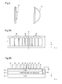
Fig. 3A is a plan view schematically showing the structure of the LED light source. -
Fig. 3B is a cross-sectional view schematically showing the structure of the LED light source. -
Fig. 4A is a schematic plan view showing an embodiment of the light-emitting units of the LED light source. -
Fig. 4B is a schematic plan view showing another embodiment of the light-emitting units of the LED light source. -
Fig. 4C is a schematic plan view showing a comparison example of the light-emitting units of the LED light source. - Now, an embodiment of the present invention will be described below with reference to the accompanying drawings.
-
Fig. 1 is a block diagram showing the configuration of a vehicle headlamp system of an embodiment. The vehicle headlamp system shown inFig. 1 sets a light distribution pattern based on an image obtained by taking an image of the space in front of the subject vehicle (target space) and irradiates light, and is configured to include acamera 10, avehicle detecting unit 11, acontrol unit 12, and a pair of lamp units (vehicle lamps) 20R and 20L. - The
camera 10 is installed in a predetermined position of the subject vehicle (near the inner rearview mirror, for example), takes an image of the space in front of the vehicle, and outputs the image (image data). - The
vehicle detecting unit 11 detects the position of the forward vehicle by performing predetermined image processing using the image data output from thecamera 10, and outputs the position information to thecontrol unit 12. The term "forward vehicle" here refers to a preceding vehicle or an oncoming vehicle. Thisvehicle detecting unit 11 is achieved by executing a predetermined operation program in a computer system comprising a CPU, ROM, RAM, and the like, for example. Thevehicle detecting unit 11 is integrally configured with thecamera 10, for example. Note that the function of thevehicle detecting unit 11 may be achieved in thecontrol unit 12. - The
control unit 12 is achieved by executing a predetermined operation program in a computer system comprising a CPU, ROM, RAM, and the like, for example, and comprises a light irradiationrange setting unit 14 and a lightdistribution control unit 15 as function blocks. - The light irradiation
range setting unit 14 sets the light irradiation range corresponding to the position of the forward vehicle detected by thevehicle detecting unit 11. Specifically, the light irradiationrange setting unit 14 sets the area where the forward vehicle exists as a light non-irradiation range, and all other areas as the light irradiation range. - The light
distribution control unit 15 generates a light distribution control signal corresponding to the light distribution pattern based on the light irradiation range and non-irradiation range set by the light irradiationrange setting unit 14, and outputs the light distribution control signal to therespective lamp units - The
lamp unit 20R is installed on the front right side of the subject vehicle, and is used to irradiate light that illuminates the area in front of the vehicle, and comprises alighting circuit 21 and anLED light source 22. Similarly, thelamp unit 20L is installed on the front left side of the subject vehicle, and is used to irradiate light that illuminates the area in front of the vehicle, and comprises thelighting circuit 21 and theLED light source 22. - The
lighting circuit 21 selectively turns on the respective LEDs by supplying a drive signal to the plurality of LEDs (light-emitting diodes) included in theLED light source 22, based on the control signal output from the lightdistribution control unit 15. - The
LED light source 22 comprises a plurality of LEDs, and each of the plurality of LEDs is selectively turned on based on the drive signal supplied from thelighting circuit 21. ThisLED light source 22 is capable of individually turning on each of the plurality of LEDs and controlling the light intensity (brightness) thereof. -
Fig. 2 is a schematic diagram showing the optical configuration of the lamp unit. As shown inFig. 2 , thelamp unit 20R (or 20L) comprises theLED light source 22 described above and a lens (projection lens) 23 disposed on the front surface thereof, and the light emitted from theLED light source 22 is projected frontward by thelens 23, thereby forming a beam such as a high beam, a low beam or an irradiation area control beam (ADB: Adaptive Driving Beam) of the light emission area. -
Fig. 3A is a plan view schematically showing the structure of the LED light source. As shown inFig. 3A , theLED light source 22 comprises a plurality of light-emittingunits 30 arranged in direction x (the left-right direction in the figure in this example). The respective light-emitting units 30 are separated from each other with spaces therebetween. Further, the respective light-emitting units 30 increase in width (length in the direction x) in proportion to the distance away from a predetermined reference position M. In this example, the widths of the respective light-emitting units 30 are set so as to increase in proportion to the distance away from the reference position M at equal ratio intervals. In this example, the lengths in direction y (the up-down direction in the figure in this example) of the respective light-emitting units 30 are the same for every light-emittingunit 30. -
Fig. 3B is a cross-sectional view schematically showing the structure of the LED light source. As shown in the figure, theLED light source 22 comprises an n-type GaN layer 31, an InGaN/GaN light-emittinglayer 32 layered on the upper side thereof, a p-type GaN layer 33 layered on the upper side thereof, a plurality ofindividual electrodes 34 provided on the upper side thereof, and acommon electrode 35 connected to the n-type GaN layer 31. The respectiveindividual electrodes 34 of this example are configured by patterning the p-type GaN film. Further, thecommon electrode 35 is configured by patterning the n-type GaN film. In this example, the widths (length in the direction x) of the respectiveindividual electrodes 34 correspond to the widths of the respective light-emittingunits 30 described above. The widths of the respectiveindividual electrodes 34 may be determined when the p-type GaN film is patterned. -
Fig. 4A is a schematic plan view showing an embodiment of the light-emitting units of the LED light source.Fig. 4B is a schematic plan view showing another embodiment of the light-emitting units of the LED light source.Fig. 4C is a schematic plan view showing a comparison example of the light-emitting units of the LED light source. - The
LED light source 22 of the embodiment shown inFig. 4A (hereinafter referred to as "embodiment 1 ") comprises nine light-emittingunits 30a-30i, with an overall width W of 4.2 mm and a length L of 0.8 mm. With the position of the light-emittingunit 30a serving as the reference position, the nine light-emittingunits 30a and the like increase in width in proportion to the distance away from the light-emittingunit 30a. Specifically, the respective light-emitting units arranged rightward from the light-emittingunit 30a increase in width in the order of the light-emittingunit 30b, the light-emittingunit 30c, the light-emittingunit 30d, and the light-emittingunit 30e. Similarly, the respective light-emitting units arranged leftward from the light-emittingunit 30a increase in width in the order of the light-emittingunit 30f, the light-emittingunit 30g, the light-emittingunit 30h, and the light-emittingunit 30i. - In this embodiment 1 as well, the widths of the respective light-emitting
units 30a and the like are set at equal ratio intervals. In embodiment 1, the light-emittingunit 30a with the smallest width is set to a width of 180 µm. With this arrangement, it is possible to set the distant viewing angle when the irradiation and extinction areas (light distribution areas) are provided in the center area in front of the vehicle to 0.22°. In such a case, the minimum irradiation width of the road surface at 100 m in front of the vehicle is 40 cm, and the minimum irradiation adjustment width of the road surface is also 40 cm. Then, the distant viewing angle that is subject to irradiation or extinction increases at an equal ratio from the center area in front of the vehicle toward the side areas. This irradiation/extinction area width is 180 µm for the narrowest light-emittingunit 30a, and 460 µm for each of the widest light-emittingunits - The LED light source of the comparison example shown in
Fig. 4C comprises nine light-emittingunits 130a-130i, similar to embodiment 1, but the widths of the respective light-emittingunits 130a and the like are identically set (at equal intervals). Specifically, the widths of the respective light-emittingunits 130a and the like are all set to 460 µm. In such a case, the minimum distant viewing angle is 0.57°, the minimum irradiation width of the road surface at 100 m in front of the vehicle is 100 cm, and the minimum irradiation adjustment width is also 100 cm. In contrast with such a comparison example, theLED light source 22 of embodiment 1 is capable of increasing the spatial resolution of light distribution control in proportion to the distance near the reference position while not increasing but rather keeping as is the number of light-emitting units to be controlled, in other words, the number of individual electrodes to be controlled. This reference position is made to correspond to the center area in front of the subject vehicle, thereby making it possible to alleviate the sense of discomfort when the shaded range is switched during light distribution control of the center area in front of the subject vehicle. - The
LED light source 22 of the embodiment shown inFig. 4B (hereinafter referred to as "embodiment 2") comprises thirty one light-emittingunits 30, with an overall width W of 4.2 mm and a length L of 0.8 mm. In this embodiment 2 as well, with the position of the light-emittingunit 30 located in the center area serving as the reference position, the thirty one light-emittingunits 30 increase in width in proportion to the distance away from the light-emittingunit 30 located in the center. In comparison with embodiment 1 described above, this embodiment similarly sets the widths of the respective light-emittingunits 30 at equal ratio intervals, but sets the widths of the respective light-emittingunits 30 smaller. Specifically, the light-emittingunit 30 with the smallest width is set to a width of 40 µm. - When this
LED light source 22 is subject to lighting control, the device separation width is not made to match the width of the irradiation/extinction areas, but rather the width of the radiation/extinction areas is set larger. Specifically, similar to embodiment 1 described above, the width of the irradiation/extinction areas is set to 180 µm. In such a case, the distant viewing angle when the irradiation/extinction areas are provided in the center area in front of the vehicle is similarly 0.22°. Then, the minimum irradiation width of the road surface at 100 m in front of the vehicle is 40 cm. However, since the widths of the respective light-emittingunits 30 are smaller, the minimum irradiation adjustment width of the road surface is 8 cm, a smaller value. As a result, the spatial resolution of light distribution control is higher compared to embodiment 1, making finer lighting control possible. For example, in a case where the extinction areas are preferably moved from the left to the right, sequential lighting control is performed so that the leftmost light-emitting unit of the extinction areas at a certain point in time is turned on and the rightmost light-emitting unit is turned off. With this arrangement, it is possible to achieve a smoother movement effect in comparison to the comparison example or embodiment 1, and further alleviate the sense of discomfort of the driver and others. - Thus, according to this embodiment, the plurality of light-emitting units decreases in width in proportion to the distance near and increases in width in proportion to the distance away from the reference position, making it possible to set light distribution areas that are narrower near the center area in front of the subject vehicle during light distribution control by installing the vehicle lamps on the vehicle so that the light emitted from these light-emitting units is projected in front of the subject vehicle by a lens or the like. As a result,, there is a decrease in the visual light movement when the light distribution areas near the center area in front of the subject vehicle where the viewing frequency of the driver and others is relatively high are switched, making it possible to alleviate the sense of discomfort of the driver and others.
- Note that this invention is not limited to the subject matter of the foregoing embodiments, and can be implemented by being variously modified within the scope of the gist of the present invention. For example, while the position information of a pedestrian and a forward vehicle is obtained by angles in the embodiments described above, the position information may be expressed by two-dimensional coordinates. Further, while the configuration of the LED light source for irradiating the high beam has been described in the embodiments described above, this LED light source may further comprise a configuration for irradiating the low beam.
Claims (16)
- A vehicle lamp configured to include a light source, wherein:the light source comprises a plurality of light-emitting units respectively comprising a control terminal for controlling light emission and extinction, arranged along a first direction, andthe plurality of light-emitting units increases in a width of a first direction in proportion to a distance away from a predetermined reference position toward both sides along the first direction, with the width of a light-emitting unit corresponding to the predetermined reference position being the smallest.
- A vehicle lamp configured to include a light source, wherein:the light source comprises a plurality of light-emitting units respectively comprising a control terminal for controlling light emission and extinction, arranged along a first direction,the plurality of light-emitting units increases in a width of a first direction in proportion to a distance away from a predetermined reference position toward both sides along the first direction, with the width of a light-emitting unit corresponding to the predetermined reference position being the smallest, andthe respective widths of the plurality of light-emitting units is set so as to increase in proportion to the distance away from the reference position at equal ratio intervals.
- A vehicle lamp configured to include a light source, wherein:the light source comprises a plurality of light-emitting units respectively comprising a control terminal for controlling light emission and extinction, arranged along a first direction,the plurality of light-emitting units increases in a width of a first direction in proportion to a distance away from a predetermined reference position toward both sides along the first direction, with the width of a light-emitting unit corresponding to the predetermined reference position being the smallest, andwherein the light source comprises a common electrode, a plurality of individual electrodes, and a light-emitting layer disposed between the common electrode and the plurality of individual electrodes, and the respective areas corresponding to the plurality of individual electrodes are equivalent to the plurality of light-emitting units.
- The vehicle lamp according to claim 2,
wherein the light source comprises a common electrode, a plurality of individual electrodes, and a light-emitting layer disposed between the common electrode and the plurality of individual electrodes, and the respective areas corresponding to the plurality of individual electrodes are equivalent to the plurality of light-emitting units. - The vehicle lamp according to claim 1,
wherein the respective widths of the plurality of individual electrodes correspond to the respective widths of the first direction of the plurality of light-emitting units. - The vehicle lamp according to claim 2,
wherein the respective widths of the plurality of individual electrodes correspond to the respective widths of the first direction of the plurality of light-emitting units. - The vehicle lamp according to claim 3,
wherein the respective widths of the plurality of individual electrodes correspond to the respective widths of the first direction of the plurality of light-emitting units. - The vehicle lamp according to claim 4,
wherein the respective widths of the plurality of individual electrodes correspond to the respective widths of the first direction of the plurality of light-emitting units. - A vehicle headlamp system configured to include the vehicle lamp described in claim 1 and a lighting control apparatus that controls the vehicle lamp.
- A vehicle headlamp system configured to include the vehicle lamp described in claim 2 and a lighting control apparatus that controls the vehicle lamp.
- A vehicle headlamp system configured to include the vehicle lamp described in claim 3 and a lighting control apparatus that controls the vehicle lamp.
- A vehicle headlamp system configured to include the vehicle lamp described in claim 4 and a lighting control apparatus that controls the vehicle lamp.
- A vehicle headlamp system configured to include the vehicle lamp described in claim 5 and a lighting control apparatus that controls the vehicle lamp.
- A vehicle headlamp system configured to include the vehicle lamp described in claim 6 and a lighting control apparatus that controls the vehicle lamp.
- A vehicle headlamp system configured to include the vehicle lamp described in claim 7 and a lighting control apparatus that controls the vehicle lamp.
- A vehicle headlamp system configured to include the vehicle lamp described in claim 8 and a lighting control apparatus that controls the vehicle lamp.
Applications Claiming Priority (1)
| Application Number | Priority Date | Filing Date | Title |
|---|---|---|---|
| JP2013134076A JP2015011772A (en) | 2013-06-26 | 2013-06-26 | Light-emitting device and vehicle headlamp system |
Publications (2)
| Publication Number | Publication Date |
|---|---|
| EP2818793A2 true EP2818793A2 (en) | 2014-12-31 |
| EP2818793A3 EP2818793A3 (en) | 2015-08-12 |
Family
ID=51032956
Family Applications (1)
| Application Number | Title | Priority Date | Filing Date |
|---|---|---|---|
| EP14173687.6A Withdrawn EP2818793A3 (en) | 2013-06-26 | 2014-06-24 | Light-emitting apparatus and vehicle headlamp system |
Country Status (3)
| Country | Link |
|---|---|
| US (1) | US20150003100A1 (en) |
| EP (1) | EP2818793A3 (en) |
| JP (1) | JP2015011772A (en) |
Cited By (3)
| Publication number | Priority date | Publication date | Assignee | Title |
|---|---|---|---|---|
| WO2017121560A1 (en) * | 2016-01-14 | 2017-07-20 | Volkswagen Aktiengesellschaft | Headlight system and method for making available a cornering light function |
| EP3671012A1 (en) * | 2018-12-18 | 2020-06-24 | ZKW Group GmbH | Motor vehicle headlamp and lighting device for a motor vehicle headlamp |
| CN112622745A (en) * | 2020-12-10 | 2021-04-09 | 大运汽车股份有限公司 | Intelligent control system and control method for car lamp |
Families Citing this family (5)
| Publication number | Priority date | Publication date | Assignee | Title |
|---|---|---|---|---|
| JP6683438B2 (en) * | 2015-08-25 | 2020-04-22 | スタンレー電気株式会社 | Vehicle headlight system |
| JP6659436B2 (en) * | 2016-04-20 | 2020-03-04 | スタンレー電気株式会社 | Vehicle lighting method and vehicle lamp |
| JP6924559B2 (en) * | 2016-05-25 | 2021-08-25 | スタンレー電気株式会社 | Light emitting diode device |
| CN111442226A (en) * | 2019-01-16 | 2020-07-24 | 光宝电子(广州)有限公司 | Illumination method, illumination device and illumination system |
| JP7131501B2 (en) * | 2019-07-29 | 2022-09-06 | トヨタ自動車株式会社 | Vehicle headlight device |
Citations (1)
| Publication number | Priority date | Publication date | Assignee | Title |
|---|---|---|---|---|
| JP4624257B2 (en) | 2005-12-28 | 2011-02-02 | 株式会社小糸製作所 | Vehicle lighting |
Family Cites Families (9)
| Publication number | Priority date | Publication date | Assignee | Title |
|---|---|---|---|---|
| JP2828187B2 (en) * | 1993-04-08 | 1998-11-25 | 日亜化学工業株式会社 | Gallium nitride based compound semiconductor light emitting device |
| JP4349414B2 (en) * | 2006-12-15 | 2009-10-21 | トヨタ自動車株式会社 | Vehicle lighting device |
| WO2008075615A1 (en) * | 2006-12-21 | 2008-06-26 | Semiconductor Energy Laboratory Co., Ltd. | Light-emitting element and light-emitting device |
| JP5069985B2 (en) * | 2007-09-13 | 2012-11-07 | 株式会社小糸製作所 | Vehicle headlamp lamp unit and vehicle headlamp |
| JP2009179113A (en) * | 2008-01-29 | 2009-08-13 | Koito Mfg Co Ltd | Vehicle headlamp device and control method thereof |
| JP5255301B2 (en) * | 2008-03-12 | 2013-08-07 | 株式会社小糸製作所 | Vehicle headlamp device |
| JP5280074B2 (en) * | 2008-03-14 | 2013-09-04 | 株式会社小糸製作所 | Vehicle headlamp device |
| DE102012008833B4 (en) * | 2012-04-28 | 2018-12-27 | Daimler Ag | Lighting arrangement and vehicle headlights |
| GB2504334A (en) * | 2012-07-26 | 2014-01-29 | Sharp Kk | Headlight system with adaptive beams |
-
2013
- 2013-06-26 JP JP2013134076A patent/JP2015011772A/en active Pending
-
2014
- 2014-06-17 US US14/306,545 patent/US20150003100A1/en not_active Abandoned
- 2014-06-24 EP EP14173687.6A patent/EP2818793A3/en not_active Withdrawn
Patent Citations (1)
| Publication number | Priority date | Publication date | Assignee | Title |
|---|---|---|---|---|
| JP4624257B2 (en) | 2005-12-28 | 2011-02-02 | 株式会社小糸製作所 | Vehicle lighting |
Cited By (5)
| Publication number | Priority date | Publication date | Assignee | Title |
|---|---|---|---|---|
| WO2017121560A1 (en) * | 2016-01-14 | 2017-07-20 | Volkswagen Aktiengesellschaft | Headlight system and method for making available a cornering light function |
| US10752162B2 (en) | 2016-01-14 | 2020-08-25 | Volkswagen Aktiengesellschaft | Headlight system and method for providing a bending light function |
| EP3671012A1 (en) * | 2018-12-18 | 2020-06-24 | ZKW Group GmbH | Motor vehicle headlamp and lighting device for a motor vehicle headlamp |
| WO2020127083A1 (en) * | 2018-12-18 | 2020-06-25 | Zkw Group Gmbh | Lighting device for a motor vehicle headlight, and motor vehicle headlight |
| CN112622745A (en) * | 2020-12-10 | 2021-04-09 | 大运汽车股份有限公司 | Intelligent control system and control method for car lamp |
Also Published As
| Publication number | Publication date |
|---|---|
| EP2818793A3 (en) | 2015-08-12 |
| US20150003100A1 (en) | 2015-01-01 |
| JP2015011772A (en) | 2015-01-19 |
Similar Documents
| Publication | Publication Date | Title |
|---|---|---|
| US20150003100A1 (en) | Light-emitting apparatus and vehicle headlamp system | |
| EP2821282B1 (en) | Light source apparatus, vehicle headlamp and vehicle headlamp system | |
| EP2826667B1 (en) | Vehicle headlamp and vehicle headlamp system | |
| JP6218499B2 (en) | Lighting control device for vehicle headlamp, vehicle headlamp system | |
| EP2567867B1 (en) | Vehicle headlamp and system for controlling the same | |
| JP5992278B2 (en) | Lighting control device for vehicle headlamp, vehicle headlamp system | |
| EP2578452B2 (en) | Vehicle spot lamp control device and vehicle spot lamp system | |
| JP5199798B2 (en) | Vehicle headlamp device | |
| JP6889588B2 (en) | Vehicle lighting | |
| JP2016215692A (en) | Lighting control device for vehicle headlamp, vehicle headlamp system | |
| JP5823214B2 (en) | Vehicle headlamp device | |
| JP6663168B2 (en) | Vehicle headlamp lighting control device, vehicle headlamp system | |
| JP6924559B2 (en) | Light emitting diode device | |
| JP5819153B2 (en) | Vehicle headlamp device | |
| JP2016083987A (en) | Vehicular lighting system and on-vehicle system | |
| CN115190848A (en) | Vehicle headlamps | |
| JP2013147111A (en) | Lighting control device for vehicle front light, and vehicle front light system | |
| JPWO2015119046A1 (en) | Vehicle lamp control system | |
| JP2014101069A (en) | Lighting control unit of vehicular headlamps, and vehicular headlamp system | |
| JP7052165B2 (en) | Headlight controller | |
| JP2013154741A (en) | Lighting controller of vehicle headlight and vehicle headlight system | |
| JP6235814B2 (en) | Lighting control system | |
| JP2015033954A (en) | Lighting control device for vehicle headlamp, vehicle headlamp system | |
| JP6192955B2 (en) | Lighting control device for vehicle headlamp, vehicle headlamp system | |
| JP2015116915A (en) | Lighting control device of headlight for vehicle, and headlight system for vehicle |
Legal Events
| Date | Code | Title | Description |
|---|---|---|---|
| PUAI | Public reference made under article 153(3) epc to a published international application that has entered the european phase |
Free format text: ORIGINAL CODE: 0009012 |
|
| 17P | Request for examination filed |
Effective date: 20140624 |
|
| AK | Designated contracting states |
Kind code of ref document: A2 Designated state(s): AL AT BE BG CH CY CZ DE DK EE ES FI FR GB GR HR HU IE IS IT LI LT LU LV MC MK MT NL NO PL PT RO RS SE SI SK SM TR |
|
| AX | Request for extension of the european patent |
Extension state: BA ME |
|
| PUAL | Search report despatched |
Free format text: ORIGINAL CODE: 0009013 |
|
| AK | Designated contracting states |
Kind code of ref document: A3 Designated state(s): AL AT BE BG CH CY CZ DE DK EE ES FI FR GB GR HR HU IE IS IT LI LT LU LV MC MK MT NL NO PL PT RO RS SE SI SK SM TR |
|
| AX | Request for extension of the european patent |
Extension state: BA ME |
|
| RIC1 | Information provided on ipc code assigned before grant |
Ipc: H01L 33/38 20100101ALI20150708BHEP Ipc: H01L 33/32 20100101ALI20150708BHEP Ipc: B60Q 1/14 20060101ALI20150708BHEP Ipc: F21V 23/00 20150101ALI20150708BHEP Ipc: F21S 8/10 20060101AFI20150708BHEP |
|
| R17P | Request for examination filed (corrected) |
Effective date: 20160212 |
|
| RBV | Designated contracting states (corrected) |
Designated state(s): AL AT BE BG CH CY CZ DE DK EE ES FI FR GB GR HR HU IE IS IT LI LT LU LV MC MK MT NL NO PL PT RO RS SE SI SK SM TR |
|
| STAA | Information on the status of an ep patent application or granted ep patent |
Free format text: STATUS: THE APPLICATION IS DEEMED TO BE WITHDRAWN |
|
| 18D | Application deemed to be withdrawn |
Effective date: 20180103 |