EP2818404A1 - Foam stiffened structure and method of making the same - Google Patents
Foam stiffened structure and method of making the same Download PDFInfo
- Publication number
- EP2818404A1 EP2818404A1 EP20140164626 EP14164626A EP2818404A1 EP 2818404 A1 EP2818404 A1 EP 2818404A1 EP 20140164626 EP20140164626 EP 20140164626 EP 14164626 A EP14164626 A EP 14164626A EP 2818404 A1 EP2818404 A1 EP 2818404A1
- Authority
- EP
- European Patent Office
- Prior art keywords
- foam
- skin
- foam member
- density
- mold
- Prior art date
- Legal status (The legal status is an assumption and is not a legal conclusion. Google has not performed a legal analysis and makes no representation as to the accuracy of the status listed.)
- Granted
Links
Images



Classifications
-
- B—PERFORMING OPERATIONS; TRANSPORTING
- B32—LAYERED PRODUCTS
- B32B—LAYERED PRODUCTS, i.e. PRODUCTS BUILT-UP OF STRATA OF FLAT OR NON-FLAT, e.g. CELLULAR OR HONEYCOMB, FORM
- B32B3/00—Layered products comprising a layer with external or internal discontinuities or unevennesses, or a layer of non-planar shape; Layered products comprising a layer having particular features of form
- B32B3/02—Layered products comprising a layer with external or internal discontinuities or unevennesses, or a layer of non-planar shape; Layered products comprising a layer having particular features of form characterised by features of form at particular places, e.g. in edge regions
- B32B3/08—Layered products comprising a layer with external or internal discontinuities or unevennesses, or a layer of non-planar shape; Layered products comprising a layer having particular features of form characterised by features of form at particular places, e.g. in edge regions characterised by added members at particular parts
-
- B—PERFORMING OPERATIONS; TRANSPORTING
- B29—WORKING OF PLASTICS; WORKING OF SUBSTANCES IN A PLASTIC STATE IN GENERAL
- B29C—SHAPING OR JOINING OF PLASTICS; SHAPING OF MATERIAL IN A PLASTIC STATE, NOT OTHERWISE PROVIDED FOR; AFTER-TREATMENT OF THE SHAPED PRODUCTS, e.g. REPAIRING
- B29C44/00—Shaping by internal pressure generated in the material, e.g. swelling or foaming ; Producing porous or cellular expanded plastics articles
- B29C44/02—Shaping by internal pressure generated in the material, e.g. swelling or foaming ; Producing porous or cellular expanded plastics articles for articles of definite length, i.e. discrete articles
- B29C44/025—Foaming in open moulds, followed by closing the moulds
-
- B—PERFORMING OPERATIONS; TRANSPORTING
- B29—WORKING OF PLASTICS; WORKING OF SUBSTANCES IN A PLASTIC STATE IN GENERAL
- B29C—SHAPING OR JOINING OF PLASTICS; SHAPING OF MATERIAL IN A PLASTIC STATE, NOT OTHERWISE PROVIDED FOR; AFTER-TREATMENT OF THE SHAPED PRODUCTS, e.g. REPAIRING
- B29C44/00—Shaping by internal pressure generated in the material, e.g. swelling or foaming ; Producing porous or cellular expanded plastics articles
- B29C44/02—Shaping by internal pressure generated in the material, e.g. swelling or foaming ; Producing porous or cellular expanded plastics articles for articles of definite length, i.e. discrete articles
- B29C44/04—Shaping by internal pressure generated in the material, e.g. swelling or foaming ; Producing porous or cellular expanded plastics articles for articles of definite length, i.e. discrete articles consisting of at least two parts of chemically or physically different materials, e.g. having different densities
- B29C44/0415—Shaping by internal pressure generated in the material, e.g. swelling or foaming ; Producing porous or cellular expanded plastics articles for articles of definite length, i.e. discrete articles consisting of at least two parts of chemically or physically different materials, e.g. having different densities by regulating the pressure of the material during or after filling of the mould, e.g. by local venting
-
- B—PERFORMING OPERATIONS; TRANSPORTING
- B29—WORKING OF PLASTICS; WORKING OF SUBSTANCES IN A PLASTIC STATE IN GENERAL
- B29C—SHAPING OR JOINING OF PLASTICS; SHAPING OF MATERIAL IN A PLASTIC STATE, NOT OTHERWISE PROVIDED FOR; AFTER-TREATMENT OF THE SHAPED PRODUCTS, e.g. REPAIRING
- B29C44/00—Shaping by internal pressure generated in the material, e.g. swelling or foaming ; Producing porous or cellular expanded plastics articles
- B29C44/02—Shaping by internal pressure generated in the material, e.g. swelling or foaming ; Producing porous or cellular expanded plastics articles for articles of definite length, i.e. discrete articles
- B29C44/08—Shaping by internal pressure generated in the material, e.g. swelling or foaming ; Producing porous or cellular expanded plastics articles for articles of definite length, i.e. discrete articles using several expanding or moulding steps
- B29C44/083—Increasing the size of the cavity after a first part has foamed, e.g. substituting one mould part with another
- B29C44/086—Increasing the size of the cavity after a first part has foamed, e.g. substituting one mould part with another and feeding more material into the enlarged cavity
-
- B—PERFORMING OPERATIONS; TRANSPORTING
- B29—WORKING OF PLASTICS; WORKING OF SUBSTANCES IN A PLASTIC STATE IN GENERAL
- B29C—SHAPING OR JOINING OF PLASTICS; SHAPING OF MATERIAL IN A PLASTIC STATE, NOT OTHERWISE PROVIDED FOR; AFTER-TREATMENT OF THE SHAPED PRODUCTS, e.g. REPAIRING
- B29C44/00—Shaping by internal pressure generated in the material, e.g. swelling or foaming ; Producing porous or cellular expanded plastics articles
- B29C44/02—Shaping by internal pressure generated in the material, e.g. swelling or foaming ; Producing porous or cellular expanded plastics articles for articles of definite length, i.e. discrete articles
- B29C44/10—Applying counter-pressure during expanding
-
- B—PERFORMING OPERATIONS; TRANSPORTING
- B29—WORKING OF PLASTICS; WORKING OF SUBSTANCES IN A PLASTIC STATE IN GENERAL
- B29C—SHAPING OR JOINING OF PLASTICS; SHAPING OF MATERIAL IN A PLASTIC STATE, NOT OTHERWISE PROVIDED FOR; AFTER-TREATMENT OF THE SHAPED PRODUCTS, e.g. REPAIRING
- B29C44/00—Shaping by internal pressure generated in the material, e.g. swelling or foaming ; Producing porous or cellular expanded plastics articles
- B29C44/34—Auxiliary operations
- B29C44/58—Moulds
- B29C44/588—Moulds with means for venting, e.g. releasing foaming gas
-
- B—PERFORMING OPERATIONS; TRANSPORTING
- B29—WORKING OF PLASTICS; WORKING OF SUBSTANCES IN A PLASTIC STATE IN GENERAL
- B29C—SHAPING OR JOINING OF PLASTICS; SHAPING OF MATERIAL IN A PLASTIC STATE, NOT OTHERWISE PROVIDED FOR; AFTER-TREATMENT OF THE SHAPED PRODUCTS, e.g. REPAIRING
- B29C44/00—Shaping by internal pressure generated in the material, e.g. swelling or foaming ; Producing porous or cellular expanded plastics articles
- B29C44/34—Auxiliary operations
- B29C44/60—Measuring, controlling or regulating
-
- B—PERFORMING OPERATIONS; TRANSPORTING
- B32—LAYERED PRODUCTS
- B32B—LAYERED PRODUCTS, i.e. PRODUCTS BUILT-UP OF STRATA OF FLAT OR NON-FLAT, e.g. CELLULAR OR HONEYCOMB, FORM
- B32B1/00—Layered products having a non-planar shape
-
- B—PERFORMING OPERATIONS; TRANSPORTING
- B32—LAYERED PRODUCTS
- B32B—LAYERED PRODUCTS, i.e. PRODUCTS BUILT-UP OF STRATA OF FLAT OR NON-FLAT, e.g. CELLULAR OR HONEYCOMB, FORM
- B32B5/00—Layered products characterised by the non- homogeneity or physical structure, i.e. comprising a fibrous, filamentary, particulate or foam layer; Layered products characterised by having a layer differing constitutionally or physically in different parts
- B32B5/18—Layered products characterised by the non- homogeneity or physical structure, i.e. comprising a fibrous, filamentary, particulate or foam layer; Layered products characterised by having a layer differing constitutionally or physically in different parts characterised by features of a layer of foamed material
-
- B—PERFORMING OPERATIONS; TRANSPORTING
- B32—LAYERED PRODUCTS
- B32B—LAYERED PRODUCTS, i.e. PRODUCTS BUILT-UP OF STRATA OF FLAT OR NON-FLAT, e.g. CELLULAR OR HONEYCOMB, FORM
- B32B5/00—Layered products characterised by the non- homogeneity or physical structure, i.e. comprising a fibrous, filamentary, particulate or foam layer; Layered products characterised by having a layer differing constitutionally or physically in different parts
- B32B5/22—Layered products characterised by the non- homogeneity or physical structure, i.e. comprising a fibrous, filamentary, particulate or foam layer; Layered products characterised by having a layer differing constitutionally or physically in different parts characterised by the presence of two or more layers which are next to each other and are fibrous, filamentary, formed of particles or foamed
- B32B5/24—Layered products characterised by the non- homogeneity or physical structure, i.e. comprising a fibrous, filamentary, particulate or foam layer; Layered products characterised by having a layer differing constitutionally or physically in different parts characterised by the presence of two or more layers which are next to each other and are fibrous, filamentary, formed of particles or foamed one layer being a fibrous or filamentary layer
- B32B5/245—Layered products characterised by the non- homogeneity or physical structure, i.e. comprising a fibrous, filamentary, particulate or foam layer; Layered products characterised by having a layer differing constitutionally or physically in different parts characterised by the presence of two or more layers which are next to each other and are fibrous, filamentary, formed of particles or foamed one layer being a fibrous or filamentary layer another layer next to it being a foam layer
-
- B—PERFORMING OPERATIONS; TRANSPORTING
- B32—LAYERED PRODUCTS
- B32B—LAYERED PRODUCTS, i.e. PRODUCTS BUILT-UP OF STRATA OF FLAT OR NON-FLAT, e.g. CELLULAR OR HONEYCOMB, FORM
- B32B5/00—Layered products characterised by the non- homogeneity or physical structure, i.e. comprising a fibrous, filamentary, particulate or foam layer; Layered products characterised by having a layer differing constitutionally or physically in different parts
- B32B5/22—Layered products characterised by the non- homogeneity or physical structure, i.e. comprising a fibrous, filamentary, particulate or foam layer; Layered products characterised by having a layer differing constitutionally or physically in different parts characterised by the presence of two or more layers which are next to each other and are fibrous, filamentary, formed of particles or foamed
- B32B5/24—Layered products characterised by the non- homogeneity or physical structure, i.e. comprising a fibrous, filamentary, particulate or foam layer; Layered products characterised by having a layer differing constitutionally or physically in different parts characterised by the presence of two or more layers which are next to each other and are fibrous, filamentary, formed of particles or foamed one layer being a fibrous or filamentary layer
- B32B5/26—Layered products characterised by the non- homogeneity or physical structure, i.e. comprising a fibrous, filamentary, particulate or foam layer; Layered products characterised by having a layer differing constitutionally or physically in different parts characterised by the presence of two or more layers which are next to each other and are fibrous, filamentary, formed of particles or foamed one layer being a fibrous or filamentary layer another layer next to it also being fibrous or filamentary
-
- B—PERFORMING OPERATIONS; TRANSPORTING
- B32—LAYERED PRODUCTS
- B32B—LAYERED PRODUCTS, i.e. PRODUCTS BUILT-UP OF STRATA OF FLAT OR NON-FLAT, e.g. CELLULAR OR HONEYCOMB, FORM
- B32B5/00—Layered products characterised by the non- homogeneity or physical structure, i.e. comprising a fibrous, filamentary, particulate or foam layer; Layered products characterised by having a layer differing constitutionally or physically in different parts
- B32B5/22—Layered products characterised by the non- homogeneity or physical structure, i.e. comprising a fibrous, filamentary, particulate or foam layer; Layered products characterised by having a layer differing constitutionally or physically in different parts characterised by the presence of two or more layers which are next to each other and are fibrous, filamentary, formed of particles or foamed
- B32B5/24—Layered products characterised by the non- homogeneity or physical structure, i.e. comprising a fibrous, filamentary, particulate or foam layer; Layered products characterised by having a layer differing constitutionally or physically in different parts characterised by the presence of two or more layers which are next to each other and are fibrous, filamentary, formed of particles or foamed one layer being a fibrous or filamentary layer
- B32B5/28—Layered products characterised by the non- homogeneity or physical structure, i.e. comprising a fibrous, filamentary, particulate or foam layer; Layered products characterised by having a layer differing constitutionally or physically in different parts characterised by the presence of two or more layers which are next to each other and are fibrous, filamentary, formed of particles or foamed one layer being a fibrous or filamentary layer impregnated with or embedded in a plastic substance
-
- B—PERFORMING OPERATIONS; TRANSPORTING
- B32—LAYERED PRODUCTS
- B32B—LAYERED PRODUCTS, i.e. PRODUCTS BUILT-UP OF STRATA OF FLAT OR NON-FLAT, e.g. CELLULAR OR HONEYCOMB, FORM
- B32B7/00—Layered products characterised by the relation between layers; Layered products characterised by the relative orientation of features between layers, or by the relative values of a measurable parameter between layers, i.e. products comprising layers having different physical, chemical or physicochemical properties; Layered products characterised by the interconnection of layers
- B32B7/04—Interconnection of layers
- B32B7/06—Interconnection of layers permitting easy separation
-
- B—PERFORMING OPERATIONS; TRANSPORTING
- B32—LAYERED PRODUCTS
- B32B—LAYERED PRODUCTS, i.e. PRODUCTS BUILT-UP OF STRATA OF FLAT OR NON-FLAT, e.g. CELLULAR OR HONEYCOMB, FORM
- B32B7/00—Layered products characterised by the relation between layers; Layered products characterised by the relative orientation of features between layers, or by the relative values of a measurable parameter between layers, i.e. products comprising layers having different physical, chemical or physicochemical properties; Layered products characterised by the interconnection of layers
- B32B7/04—Interconnection of layers
- B32B7/12—Interconnection of layers using interposed adhesives or interposed materials with bonding properties
-
- B—PERFORMING OPERATIONS; TRANSPORTING
- B64—AIRCRAFT; AVIATION; COSMONAUTICS
- B64C—AEROPLANES; HELICOPTERS
- B64C1/00—Fuselages; Constructional features common to fuselages, wings, stabilising surfaces or the like
- B64C1/06—Frames; Stringers; Longerons ; Fuselage sections
- B64C1/068—Fuselage sections
-
- B—PERFORMING OPERATIONS; TRANSPORTING
- B64—AIRCRAFT; AVIATION; COSMONAUTICS
- B64C—AEROPLANES; HELICOPTERS
- B64C3/00—Wings
- B64C3/20—Integral or sandwich constructions
-
- B—PERFORMING OPERATIONS; TRANSPORTING
- B64—AIRCRAFT; AVIATION; COSMONAUTICS
- B64C—AEROPLANES; HELICOPTERS
- B64C3/00—Wings
- B64C3/24—Moulded or cast structures
-
- B—PERFORMING OPERATIONS; TRANSPORTING
- B64—AIRCRAFT; AVIATION; COSMONAUTICS
- B64C—AEROPLANES; HELICOPTERS
- B64C5/00—Stabilising surfaces
- B64C5/10—Stabilising surfaces adjustable
-
- B—PERFORMING OPERATIONS; TRANSPORTING
- B29—WORKING OF PLASTICS; WORKING OF SUBSTANCES IN A PLASTIC STATE IN GENERAL
- B29K—INDEXING SCHEME ASSOCIATED WITH SUBCLASSES B29B, B29C OR B29D, RELATING TO MOULDING MATERIALS OR TO MATERIALS FOR MOULDS, REINFORCEMENTS, FILLERS OR PREFORMED PARTS, e.g. INSERTS
- B29K2075/00—Use of PU, i.e. polyureas or polyurethanes or derivatives thereof, as moulding material
-
- B—PERFORMING OPERATIONS; TRANSPORTING
- B29—WORKING OF PLASTICS; WORKING OF SUBSTANCES IN A PLASTIC STATE IN GENERAL
- B29K—INDEXING SCHEME ASSOCIATED WITH SUBCLASSES B29B, B29C OR B29D, RELATING TO MOULDING MATERIALS OR TO MATERIALS FOR MOULDS, REINFORCEMENTS, FILLERS OR PREFORMED PARTS, e.g. INSERTS
- B29K2105/00—Condition, form or state of moulded material or of the material to be shaped
- B29K2105/04—Condition, form or state of moulded material or of the material to be shaped cellular or porous
-
- B—PERFORMING OPERATIONS; TRANSPORTING
- B29—WORKING OF PLASTICS; WORKING OF SUBSTANCES IN A PLASTIC STATE IN GENERAL
- B29L—INDEXING SCHEME ASSOCIATED WITH SUBCLASS B29C, RELATING TO PARTICULAR ARTICLES
- B29L2031/00—Other particular articles
- B29L2031/30—Vehicles, e.g. ships or aircraft, or body parts thereof
- B29L2031/3076—Aircrafts
-
- B—PERFORMING OPERATIONS; TRANSPORTING
- B32—LAYERED PRODUCTS
- B32B—LAYERED PRODUCTS, i.e. PRODUCTS BUILT-UP OF STRATA OF FLAT OR NON-FLAT, e.g. CELLULAR OR HONEYCOMB, FORM
- B32B2250/00—Layers arrangement
- B32B2250/03—3 layers
-
- B—PERFORMING OPERATIONS; TRANSPORTING
- B32—LAYERED PRODUCTS
- B32B—LAYERED PRODUCTS, i.e. PRODUCTS BUILT-UP OF STRATA OF FLAT OR NON-FLAT, e.g. CELLULAR OR HONEYCOMB, FORM
- B32B2250/00—Layers arrangement
- B32B2250/40—Symmetrical or sandwich layers, e.g. ABA, ABCBA, ABCCBA
-
- B—PERFORMING OPERATIONS; TRANSPORTING
- B32—LAYERED PRODUCTS
- B32B—LAYERED PRODUCTS, i.e. PRODUCTS BUILT-UP OF STRATA OF FLAT OR NON-FLAT, e.g. CELLULAR OR HONEYCOMB, FORM
- B32B2260/00—Layered product comprising an impregnated, embedded, or bonded layer wherein the layer comprises an impregnation, embedding, or binder material
- B32B2260/02—Composition of the impregnated, bonded or embedded layer
- B32B2260/021—Fibrous or filamentary layer
- B32B2260/023—Two or more layers
-
- B—PERFORMING OPERATIONS; TRANSPORTING
- B32—LAYERED PRODUCTS
- B32B—LAYERED PRODUCTS, i.e. PRODUCTS BUILT-UP OF STRATA OF FLAT OR NON-FLAT, e.g. CELLULAR OR HONEYCOMB, FORM
- B32B2260/00—Layered product comprising an impregnated, embedded, or bonded layer wherein the layer comprises an impregnation, embedding, or binder material
- B32B2260/04—Impregnation, embedding, or binder material
- B32B2260/046—Synthetic resin
-
- B—PERFORMING OPERATIONS; TRANSPORTING
- B32—LAYERED PRODUCTS
- B32B—LAYERED PRODUCTS, i.e. PRODUCTS BUILT-UP OF STRATA OF FLAT OR NON-FLAT, e.g. CELLULAR OR HONEYCOMB, FORM
- B32B2266/00—Composition of foam
- B32B2266/02—Organic
- B32B2266/0214—Materials belonging to B32B27/00
- B32B2266/0278—Polyurethane
-
- B—PERFORMING OPERATIONS; TRANSPORTING
- B32—LAYERED PRODUCTS
- B32B—LAYERED PRODUCTS, i.e. PRODUCTS BUILT-UP OF STRATA OF FLAT OR NON-FLAT, e.g. CELLULAR OR HONEYCOMB, FORM
- B32B2305/00—Condition, form or state of the layers or laminate
- B32B2305/02—Cellular or porous
- B32B2305/022—Foam
-
- B—PERFORMING OPERATIONS; TRANSPORTING
- B32—LAYERED PRODUCTS
- B32B—LAYERED PRODUCTS, i.e. PRODUCTS BUILT-UP OF STRATA OF FLAT OR NON-FLAT, e.g. CELLULAR OR HONEYCOMB, FORM
- B32B2305/00—Condition, form or state of the layers or laminate
- B32B2305/07—Parts immersed or impregnated in a matrix
- B32B2305/076—Prepregs
-
- B—PERFORMING OPERATIONS; TRANSPORTING
- B32—LAYERED PRODUCTS
- B32B—LAYERED PRODUCTS, i.e. PRODUCTS BUILT-UP OF STRATA OF FLAT OR NON-FLAT, e.g. CELLULAR OR HONEYCOMB, FORM
- B32B2305/00—Condition, form or state of the layers or laminate
- B32B2305/10—Fibres of continuous length
-
- B—PERFORMING OPERATIONS; TRANSPORTING
- B32—LAYERED PRODUCTS
- B32B—LAYERED PRODUCTS, i.e. PRODUCTS BUILT-UP OF STRATA OF FLAT OR NON-FLAT, e.g. CELLULAR OR HONEYCOMB, FORM
- B32B2603/00—Vanes, blades, propellers, rotors with blades
-
- B—PERFORMING OPERATIONS; TRANSPORTING
- B32—LAYERED PRODUCTS
- B32B—LAYERED PRODUCTS, i.e. PRODUCTS BUILT-UP OF STRATA OF FLAT OR NON-FLAT, e.g. CELLULAR OR HONEYCOMB, FORM
- B32B2605/00—Vehicles
- B32B2605/18—Aircraft
-
- B—PERFORMING OPERATIONS; TRANSPORTING
- B64—AIRCRAFT; AVIATION; COSMONAUTICS
- B64C—AEROPLANES; HELICOPTERS
- B64C1/00—Fuselages; Constructional features common to fuselages, wings, stabilising surfaces or the like
- B64C2001/0054—Fuselage structures substantially made from particular materials
- B64C2001/0072—Fuselage structures substantially made from particular materials from composite materials
-
- B—PERFORMING OPERATIONS; TRANSPORTING
- B64—AIRCRAFT; AVIATION; COSMONAUTICS
- B64C—AEROPLANES; HELICOPTERS
- B64C27/00—Rotorcraft; Rotors peculiar thereto
- B64C27/32—Rotors
- B64C27/46—Blades
- B64C27/473—Constructional features
- B64C2027/4733—Rotor blades substantially made from particular materials
- B64C2027/4736—Rotor blades substantially made from particular materials from composite materials
-
- Y—GENERAL TAGGING OF NEW TECHNOLOGICAL DEVELOPMENTS; GENERAL TAGGING OF CROSS-SECTIONAL TECHNOLOGIES SPANNING OVER SEVERAL SECTIONS OF THE IPC; TECHNICAL SUBJECTS COVERED BY FORMER USPC CROSS-REFERENCE ART COLLECTIONS [XRACs] AND DIGESTS
- Y02—TECHNOLOGIES OR APPLICATIONS FOR MITIGATION OR ADAPTATION AGAINST CLIMATE CHANGE
- Y02T—CLIMATE CHANGE MITIGATION TECHNOLOGIES RELATED TO TRANSPORTATION
- Y02T50/00—Aeronautics or air transport
- Y02T50/40—Weight reduction
-
- Y—GENERAL TAGGING OF NEW TECHNOLOGICAL DEVELOPMENTS; GENERAL TAGGING OF CROSS-SECTIONAL TECHNOLOGIES SPANNING OVER SEVERAL SECTIONS OF THE IPC; TECHNICAL SUBJECTS COVERED BY FORMER USPC CROSS-REFERENCE ART COLLECTIONS [XRACs] AND DIGESTS
- Y10—TECHNICAL SUBJECTS COVERED BY FORMER USPC
- Y10T—TECHNICAL SUBJECTS COVERED BY FORMER US CLASSIFICATION
- Y10T156/00—Adhesive bonding and miscellaneous chemical manufacture
- Y10T156/10—Methods of surface bonding and/or assembly therefor
-
- Y—GENERAL TAGGING OF NEW TECHNOLOGICAL DEVELOPMENTS; GENERAL TAGGING OF CROSS-SECTIONAL TECHNOLOGIES SPANNING OVER SEVERAL SECTIONS OF THE IPC; TECHNICAL SUBJECTS COVERED BY FORMER USPC CROSS-REFERENCE ART COLLECTIONS [XRACs] AND DIGESTS
- Y10—TECHNICAL SUBJECTS COVERED BY FORMER USPC
- Y10T—TECHNICAL SUBJECTS COVERED BY FORMER US CLASSIFICATION
- Y10T428/00—Stock material or miscellaneous articles
- Y10T428/23—Sheet including cover or casing
- Y10T428/233—Foamed or expanded material encased
-
- Y—GENERAL TAGGING OF NEW TECHNOLOGICAL DEVELOPMENTS; GENERAL TAGGING OF CROSS-SECTIONAL TECHNOLOGIES SPANNING OVER SEVERAL SECTIONS OF THE IPC; TECHNICAL SUBJECTS COVERED BY FORMER USPC CROSS-REFERENCE ART COLLECTIONS [XRACs] AND DIGESTS
- Y10—TECHNICAL SUBJECTS COVERED BY FORMER USPC
- Y10T—TECHNICAL SUBJECTS COVERED BY FORMER US CLASSIFICATION
- Y10T428/00—Stock material or miscellaneous articles
- Y10T428/249921—Web or sheet containing structurally defined element or component
- Y10T428/249953—Composite having voids in a component [e.g., porous, cellular, etc.]
-
- Y—GENERAL TAGGING OF NEW TECHNOLOGICAL DEVELOPMENTS; GENERAL TAGGING OF CROSS-SECTIONAL TECHNOLOGIES SPANNING OVER SEVERAL SECTIONS OF THE IPC; TECHNICAL SUBJECTS COVERED BY FORMER USPC CROSS-REFERENCE ART COLLECTIONS [XRACs] AND DIGESTS
- Y10—TECHNICAL SUBJECTS COVERED BY FORMER USPC
- Y10T—TECHNICAL SUBJECTS COVERED BY FORMER US CLASSIFICATION
- Y10T428/00—Stock material or miscellaneous articles
- Y10T428/249921—Web or sheet containing structurally defined element or component
- Y10T428/249953—Composite having voids in a component [e.g., porous, cellular, etc.]
- Y10T428/249982—With component specified as adhesive or bonding agent
Definitions
- the system of the present application relates to a structure for a vehicle, such as a rotorcraft.
- the system of the present application relates to a foam stiffened structure and method of making the foam stiffened structure.
- the system of the present application can be applied to many different structures, both static and mobile.
- the system of the present application is described herein with regard to a rotorcraft structure for exemplary purposes.
- One typical aerospace structural assembly includes an exterior aerodynamic skin with a plurality of internal structural members.
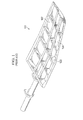
- FIG 1 an exemplary prior art airfoil structure 101 is illustrated.
- Structure 101 includes a plurality of ribs 103 and spars 105.
- the ribs 103 and spars 105 are configured to provide structural integrity to structure 101, as well as to provide support to a skin 107 (shown partially removed for clarity).
- Structure 101 requires a substantial amount of expense and effort to assembly.
- each rib 103 and spar 105 represents an individual part that must be fabricated, recorded, stocked, and assembled.
- the ribs 103, spars 105, and skin 107 are typically assembled with fasteners, usually requiring a considerable amount of effort and expense to install.
- the fasteners may promote corrosion, stress concentrations, and otherwise shorten the life of the structure.
- tolerance variations between the plurality of parts can lead to irregularities in the surface quality of skin 107.
- a structure comprises:
- the skin may be selected from a composite material and a metallic material.
- the foam member may have a side portion left exposed such that the skin member only partially envelopes the foam member.
- the foam member may be adhesively bonded to the skin member with an adhesive layer, so that the foam member is capable of carrying a shear load upon the skin member.
- a release agent may be used to prevent the foam member from being in bonding contact with the skin member, so as to substantially prevent a shear load from the skin member from being carried through the foam member.
- a density of the foam member may be tailored so that
- the skin may be an airfoil shape.
- the structure may be an airfoil member for an aircraft.
- a method of making a foam member for a structure comprises:
- the step of selectively controlling a density of the foam member may involve
- the method may further comprise:
- a method of making a composite structure comprises:
- the step of manufacturing an at least partially cured foam member may comprise:
- the method may further comprise:
- the step of laying up an uncured composite skin onto an outer surface of the foam member may be achieved with a fiber placement machine.
- the step of manufacturing an at least partially cured foam member may further comprise:
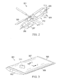
- Aircraft 201 includes main rotor blades 203, a fuselage 209, a landing gear 207, and a wing 211. Aircraft 201 further includes a tail boom assembly 212, which is an assembly of a tail boom 214, a tail fin 213, an elevator 301, and tail rotor blades 205. Elevator 301 functions to provide pitch control during flight of aircraft 201. Elevator 301 is illustrated and described herein as an embodiment of a foam stiffened structure. Further, it should be appreciated that elevator 301 is simply one example of a foam stiffened structure that can be manufactured in accordance with the method of the present application.
- aircraft 201 may be manufactured in accordance with the method of the present application.
- main rotor blade 203, tail rotor blade 205, wing 211, tail boom 214, tail fin 213, and fuselage 209 are all parts that may be manufactured in accordance with the method of the present application, so as to be stiffened by a molded foam member.
- aircraft 201 is merely exemplary of the wide variety of vehicles that may have foam stiffened structures formed from the method of the present application.
- other exemplary vehicles may include fixed wing aircraft, boats, ships, automobiles, and skateboards, to name a few.
- Elevator 301 includes a foam member 311 and a skin 307.
- foam member 311 is molded in a tool.
- skin 307 is preferably formed by placing uncured composite material onto foam member 311, such that foam member 311 acts as a tooled surface for the composite material. The composite material is subsequently cured to become a rigid skin 307.
- skin 307 is formed on a unique tooled surface and then cured.
- foam member 311 is formed by using the skin 307 as a tool by allowing the foam to expand and form inside the skin 307, thereby allowing skin 307 to act as a tool for the foam.
- skin 307 is not formed from a composite material, but rather thin sheet metal, or other semi-rigid material.
- the thin sheet metal is formed and bonded to foam member 311, such that foam member 311 acts partly as tool by dictating final surface contour location of the sheet metal.
- skin 307 includes an upper airfoil surface 315 and a lower airfoil surface 313.
- elevator 301 may include an inboard rib 303, an outboard rib 305, and a trailing edge member 309.
- Inboard rib 303, outboard rib 305, and trailing edge member 309 are exemplary of members that may be formed integrally with foam member 311, or assembled to foam member 311 in an assembly operation subsequent to the formation of foam member 311.
- Inboard rib 303, outboard rib 305, and trailing edge member 311 can be formed from any conventional manufacturing operation, such as machining, molding, casting, injection molding, compression molding, to name a few.
- an adhesive can be used to promote a bond between any of the skin 307, foam member 311, inboard rib 303, outboard rib 305, and trailing edge member 309.
- Foam member 311 provides structural stiffness to elevator 301.
- Skin 307 preferably comprise a plurality of reinforcing fibers disposed in a polymeric matrix. As discussed further herein, skin 307 is preferably placed onto foam member 311 as a plurality of uncured composite plies, and then later cured to form a rigid composite laminate. It should be appreciated that skin 307 can be formed from a variety of fiber and resin systems. It should also be appreciated that the specific composite material, or sheet metal, is implementation specific. For example, carbon fiber may be desirable in one application, while fiberglass fiber may be desirable in another application.
- the molded foam member 311 is preferably formed with a pourable and expandable structural foam in a mold, as discussed further herein.
- the molded foam member 311 is configured to provide the structural integrity to elevator 301 in a wide variety of geometries and contours. Curing of skin 307 may require pressure, such as autoclave curing pressure, for proper curing. As such, foam member 311 is configured to provide structural resistance to the pressure so as to preserve the desired surface geometry of skin 307.
- Foam member 311 is configured to be isotropic, thus the isotropic properties of foam member 311 allow it to retain structural integrity in a wide variety of geometries and contours.
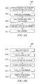
- a step 603 of method 601 includes fabricating inboard rib 303, outboard rib 305, and trailing edge member 309, which may be included in some embodiments of elevator 301. As discussed further herein, any of inboard rib 303, outboard rib 305, and trailing edge member 309 maybe located in the mold during the manufacturing of foam member 311.
- a process 605 of method 601 includes fabricating foam member 311. Referring now also to Figure 6B , process 605 is schematically illustrated in further detail. A step 613 of process 605 includes manufacturing a mold for which foam member 311 is formed within.
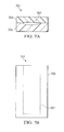
- Mold 701 preferably includes a first member 701 and a second member 703. Mold 701 also includes a cavity 707 formed partly in each of the first member 701 and a second member 703. It should be appreciated that mold 701 may be divided up into any number of separate members. Cavity 707 represents the desired geometry of foam member 311. A release agent is preferably applied to the interior of cavity 707 in order to promote the release and removal of foam member 311 from the mold 701.
- a step 615 of process 605 includes creating a foam mixture 807.
- the foam system used in the creation of foam member 311 is preferably a urethane foam system that expands to fill cavity 707 of mold 701.
- the foam is preferably rigid and flexible, while having a relatively low density.
- the preferred foam system is a polyisocyanurate pour foam system marketed under the name of Stepanfoam BX 450, by the Stepan Chemical Company. It should be fully appreciated that other foam systems may be used in the molding of foam member 311.
- the Stepanfoam BX 450 includes two separate resin components, namely a resin T (70% by weight) 805 and a resin R (30% by weight) 803.
- the desired weight amounts of resin T 805 and resin R 803 are measured and poured into a container 801.
- the resin T 805 and resin R 803 are mechanically agitated to form a homogenous mixture 807.
- a mixer 901 is used in rotation in order to mix resin T 805 and resin R 803 to form mixture 807.
- Mixer 901 includes a shaft 903, the shaft 903 being configured to be driven by a drill motor, or the like.
- Mixer 901 may include a plurality of blades located on a first blade disc 905 and a second blade disc 907. In the preferred embodiment, mixer 901 is rotated at 3500 revolutions per minute for 10-15 seconds when mixing resin T 805 and resin R 803 to form mixture 807.
- the total weight amount of mixture 807 is at least partially dependent upon the desired density and the volume of foam member 311. For example, because density is the relationship of mass per unit volume, the desired density of foam member 311 at least partially dictates the weight amount of mixture 807. However, a portion of the mixture 807 may escape from within cavity 707, which may affect the final density determination of foam member 311.
- a step 617 of process 605 includes pouring foam mixture 807 into cavity 707. Once the mixing in step 615 is complete, it is preferred that mixture 807 is poured into cavity 707 mold 701 as quickly as possible.
- a step 619 includes controlling expansion of foam mixture 807 in cavity 707.
- foam mixture 807 is allowed to "free rise" within cavity 707 so as to form foam member 311 at a "free rise” density.
- a density of approximately 8.0 pounds/ft3 and less can be achieved.
- the "free rise" embodiment of foam member 311 may be particularly desirable when the geometry and contours of foam member 311 are relatively simple. This is because the exposed surface would require a cutting or shaving operation to trim the exposed surface of foam member 311 to the desired contour.
- a "free rise” embodiment includes allowing foam mixture 807 to expand and polymerize without constraint. Expansion and polymerization of foam mixture 807 allows any volatiles to escape during the polymerization stage, and also to facilitate complete homogeneous fill of cavity 707. The polymerization stage is the expansion from a chemical reaction of the foam mixture 807.
- step 619 includes using a "captive process" to tailor the density of foam member 311.
- the captive process involves using a lid member 709 to generate pressure within cavity 707, thus inhibiting the expansion of foam mixture 807 during polymerization.
- Lid member 709 includes one or more openings 711a and 711b, which allow volatiles to escape during the polymerization of mixture 807.
- the size and number of openings 711a and 711b are also configured so as to selectively tailor the density of foam member 311.
- the openings 711a and 711b in lid member 709 are sized to create a foam member 311 having a density of approximately 12-16 pounds/ft3.
- this size and quantity of openings 711a and 711b can be increased/decreased to produce a foam member 311 of lower/higher density, respectively.
- the expected operational loading of elevator 101 is a factor that may contribute to the customization of the density of foam member 311.
- the density of foam member 311 can be customized in accordance with the desired structural strength of foam member 311.
- step 619 includes selectively positioning lid member 709 to create volumes of different densities.
- a first volume having a density of D1 is created by selectively positioning lid member 709 by a locator tool 713.
- Locator tool 713 is configured to selectively position lid member 709 as desired position.
- lid member 709 has a single opening 711a in order to produce a density of D1. It should be appreciated that density D1 can also be produced by decreasing the size of openings 711a and 711b.
- the second volume has a density D2 which is less than density D1 due to the use of both venting openings 711a and 711b.
- the density of foam member 311 can be fully customized in accordance with the predicted loading of foam member 311 in a specific implementation. For example, the inboard portion of elevator 301 may experience higher loading than the outboard portion, as such, it may be desirable for foam member 301 to have a higher density, thus higher strength, near the inboard portion.
- step 619 may involve creating any number of volumes having a variety of densities. Further, the number of volumes and densities is implementation specific. For example, if the foam stiffened structure is a large wing on an aircraft, the foam stiffened wing may have a foam member with a dozen different volumes of varying densities.
- FIG. 14A and 14B another embodiment of process 605 includes locating a form 1401 in cavity 707 so as to create a void 1403 in foam member 311.
- the inclusion of void 1403 in foam member 311 may be particularly desirable for routing wiring, or other system components, through foam member 311.
- void 1403 may also be desirable to reduce the weight of foam member 311.
- form 1401 may be a rigid tool that is removed from foam member 311.
- form 1401 is a structure that forms a bond with foam member 311 and integral with foam member 311.
- form 1401 acts as a fly-away tool in that form 1401 dictates the geometry of void 1703, and form 1401 also remains with foam member 311.
- the geometry and size of void 1403 is implementation specific and may take on a wide variety of configurations.
- another embodiment of process 605 includes incorporating components into cavity 707 of mold 701 so that such components are integral to foam member 311.
- inboard rib 303, outboard rib 305, and trailing edge member 309 can be located in cavity 707 prior to the introduction of foam mixture 807.
- foam member 311 becomes integral with inboard rib 303, outboard rib 305, and trailing edge member 309.
- an aperture 1501 in outboard rib 305 is configured to allow the escape of volatiles during expansion of foam mixture 807, similar to vent openings 711a and 711b.
- FIG. 17A and 17B another embodiment of process 605 includes incorporating a rib 1701 into cavity 707 of mold 701 so that rib 1701 is integral to foam member 311.
- rib 1701 can be located chord-wise in cavity 707 prior to the introduction of foam mixture 807.
- an aperture in rib 1701 functions as a pour opening for foam mixture 807, as well as a vent opening to allow volatiles to escape during expansion of foam mixture 807.
- venting through rib 1701 may be accomplished in a variety of ways, such as through a gap between rib 1701 and form 1401.
- foam member 311 is formed in multiple steps, similar to the procedure described above in regard to Figures 13A and 13B .
- Rib 1701 is integral with foam member 311. Rib 1701 can be used to provide supplemental structural support in elevator 301. In the illustrated embodiment, rib 1701 is located approximately mid-span, but it should be appreciated that rib 1701 may be located in a variety of locations along the span of the foam member 311. Further, it should be appreciated that even though Figures 17A and 17B are illustrated with form 1401 and void 1403, these are optional features such that some embodiments may not include form 1401 and void 1403. In another alternative embodiment, rib 1701 is introduced after a first part of foam member 311 is formed in mold 701.
- rib 1701 may be "L" shaped in order to facilitate mating of rib 1701 to the first part of foam member 311. It should be appreciated that even though only a single rib 1701 is illustrated, one embodiment includes a plurality of ribs 1701 spaced through foam member 311.
- process 605 continues with a step 621 for curing foam member 311.
- a full cure of foam member 311 is preferred before foam member 311 is removed from mold 701. The full cure is achieved by first allowing the foam member 311 to remain within mold 701 for at least 24 hours after the expanding of the foam mixture 807 within mold 701. Thereafter, the mold 701, with foam member 311 remaining therein, is cured approximately between 350° F and 375° F for approximately two hours. It should be appreciated that alternative foam systems may require different curing requirements. It is preferred that foam member 311 and mold 701 are cooled to 150° F or below, before demolding.
- a step 623 includes demolding foam member 311. Demolding foam member includes removing foam member 311 from mold 701. Demolding of foam member 311 may require pliable tools to facilitate separation of the foam member 311 from within cavity 707.
- method 601 continues with a step 607 for applying skin material to foam member 311.
- foam member 311 is removed from mold 701 in step 623 of process 605, then skin material for skin 307 can be applied to foam member 311 in a manufacturing process.
- the geometry and contours of foam member 307 are accurate to a high tolerance because of being molded in mold tool 703.
- foam member 311 is configured to act as a "fly-away tool" such that it not only acts as a tooling surface for skin 307 during assembly of elevator 301, but also remains with elevator 301 during operation of the aircraft.
- a structural bond exists between skin 307 and foam member 311 such that shearing loads are transferred between skin 307 and foam member 311 through the structural bond.
- the bond can be formed from the resin in the composite skin.
- the structural bonding can also be created or supplemented with an adhesive layer located between foam member 311 and skin 307.
- a release material may be applied to prevent a structural bond between skin 307 and foam member 311.
- step 607 includes applying uncured composite material onto foam member 311.
- the composite manufacturing process may take on a wide variety of processes because skin 307 may be formed from a wide variety of composite fiber/resin systems, or from metallic materials.
- a fiber placement machine 1601 is used to apply tape strips of composite material in a certain configuration.
- Alternative embodiments can employ any number of composite manufacturing techniques known in the art.
- Foam member 311 acts as a tool by dictating the geometry of skin 307. Because foam member 311 was formed in mold 701, the geometry and contours are highly accurate. As such, foam member 311 acts as a high tolerance support of skin 307.
- a step 611 of method 601 includes final assembly elevator 301. If inboard rib 303, outboard rib 305, and trailing edge member 309 are not already integrated with foam member 311, then step 611 includes assembling these parts with foam member 311 and skin 307. Step 611 can include assembling any other parts and performing final finish to elevator 301.
- skin 307 is cured in a step 609 of method 601.
- Skin 307, while on foam member 311, may be vacuum bagged and cured in accordance with one of a variety of conventional composite curing processes.
- curing of the skin itself is not required.
- an adhesive may be used between the metal sheet and foam member 311, as such; the adhesive may require heat and pressure for curing.
- the system of the present application provides significant advantages, including: (1) providing a stiffness producing foam member in a composite structure that can be molded in a variety of geometries and contours; (2) providing a stiffness producing foam member in a composite structure that can withstand autoclave curing pressure; (3) providing a stiffness producing foam member in a composite structure, the density of the foam member being selectively tailored; (4) providing a stiffness producing foam member in a composite structure that provides tooled support for a skin, such that the foam member not only provides structural stiffness, but also a tooling surface for the skin; and (5) providing a stiffness producing foam member in a structure, the foam member having a plurality of volumes of varying densities so that the strength/weight of the foam member is optimized for the predicted loading.
Landscapes
- Engineering & Computer Science (AREA)
- Mechanical Engineering (AREA)
- Aviation & Aerospace Engineering (AREA)
- Casting Or Compression Moulding Of Plastics Or The Like (AREA)
- Laminated Bodies (AREA)
Abstract
Description
- The system of the present application relates to a structure for a vehicle, such as a rotorcraft. In particular, the system of the present application relates to a foam stiffened structure and method of making the foam stiffened structure. The system of the present application can be applied to many different structures, both static and mobile. Furthermore, the system of the present application is described herein with regard to a rotorcraft structure for exemplary purposes.
- One typical aerospace structural assembly includes an exterior aerodynamic skin with a plurality of internal structural members. Referring to
Figure 1 , an exemplary priorart airfoil structure 101 is illustrated.Structure 101 includes a plurality ofribs 103 andspars 105. Theribs 103 andspars 105 are configured to provide structural integrity tostructure 101, as well as to provide support to a skin 107 (shown partially removed for clarity).Structure 101 requires a substantial amount of expense and effort to assembly. For example, eachrib 103 andspar 105 represents an individual part that must be fabricated, recorded, stocked, and assembled. Further, theribs 103,spars 105, andskin 107 are typically assembled with fasteners, usually requiring a considerable amount of effort and expense to install. Moreover, the fasteners may promote corrosion, stress concentrations, and otherwise shorten the life of the structure. Further, tolerance variations between the plurality of parts can lead to irregularities in the surface quality ofskin 107. - Although the developments in aerospace structures have produced significant improvements, considerable shortcomings remain.
- According to a first aspect of the invention a structure comprises:
- a foam member, the foam member having an outer molded surface; and
- a skin member located at least partially around the outer molded surface of the foam member;
- wherein the outer molded surface of the foam member is configured to provide a tooling surface for the skin member during assembly of the structure.
- The skin may be selected from a composite material and a metallic material.
- The foam member may have a side portion left exposed such that the skin member only partially envelopes the foam member.
- The foam member may be adhesively bonded to the skin member with an adhesive layer, so that the foam member is capable of carrying a shear load upon the skin member.
- A release agent may be used to prevent the foam member from being in bonding contact with the skin member, so as to substantially prevent a shear load from the skin member from being carried through the foam member.
- A density of the foam member may be tailored so that
- (i) the foam member is able to withstand a predicted pressure load that the foam member will experience during a curing cycle, and/or
- (ii) a strength of the foam member is tailored to withstand a predicted load that the foam member will experience during the lifetime of the structure.
- The skin may be an airfoil shape.
- The structure may be an airfoil member for an aircraft.
- According to a second aspect of the invention, a method of making a foam member for a structure comprises:
- creating a mold having an interior cavity which resembles a desired shape of the foam member;
- introducing a foam mixture into the mold;
- allowing the foam mixture to polymerize so as to expand and distribute within the cavity of the mold;
- selectively controlling a density of the foam member in the mold; and
- curing the foam member.
- The step of selectively controlling a density of the foam member may involve
- (i) allowing the foam mixture to free rise by not constricting a pressure within the cavity,
- (ii) using a lid member to restrict the expansion of the foam mixture, or
- (iii) selectively sizing a vent opening in a lid member.
- The method may further comprise:
- applying a release agent in the cavity of the mold prior to pouring the liquid mixture into the pour opening.
- According to a further aspect of the invention, a method of making a composite structure comprises:
- manufacturing an at least partially cured foam member;
- laying up an uncured composite skin onto an outer surface of the foam member such that the foam member acts as a tool for the uncured composite skin;
- curing the composite skin while foam member supports the portion of the composite skin.
- The step of manufacturing an at least partially cured foam member may comprise:
- creating a mold having an interior cavity which resembles a desired shape of the foam member;
- introducing a foam mixture into the mold;
- allowing the foam mixture to polymerize so as to expand and distribute within the cavity of the mold;
- selectively controlling a density of the foam member in the mold; and
- at least partially curing the foam member.
- The method may further comprise:
- applying an adhesive layer between the foam member and the uncured composite skin.
- The step of laying up an uncured composite skin onto an outer surface of the foam member may be achieved with a fiber placement machine.
- The step of manufacturing an at least partially cured foam member may further comprise:
- locating a rib within the mold.
- The novel features believed characteristic of the system of the present application are set forth in the appended claims. However, the system itself, as well as a preferred mode of use, and further objectives and advantages thereof, will best be understood by reference to the following detailed description when read in conjunction with the accompanying drawings, in which the leftmost significant digit(s) in the reference numerals denote(s) the first figure in which the respective reference numerals appear, wherein:
-
Figure 1 is a perspective view of a prior art airfoil structure; -
Figure 2 is perspective view of an aircraft, according to the preferred embodiment of the present application; -
Figure 3 is a perspective view of a foam stiffened structure, according to the preferred embodiment of the present application; -
Figure 4 is an exploded perspective view of a foam stiffened structure, according to the preferred embodiment of the present application; -
Figure 5 is a cross-sectional view of the foam stiffened structure, according to the preferred embodiment of present application, taken along the section lines 5-5, shown inFigure 3 ; -
Figure 6A is a schematic block diagram of a method for manufacturing a foam stiffened structure, according to the preferred embodiment of present application; -
Figure 6B is a schematic block diagram of a process of the method for manufacturing a foam stiffened structure, according to the preferred embodiment of present application; -
Figures 7A is a top view of a mold for manufacturing a molded foam member, according to the preferred embodiment of present application; -
Figures 7B is a front view of a mold for manufacturing a molded foam member, according to the preferred embodiment of present application; -
Figure 8 is a schematic view of components of the foam system used to manufacture a molded foam member, according to the preferred embodiment of present application; -
Figure 9 is a perspective view of a mixer used to mix the foam system, according to the preferred embodiment of present application; -
Figure 10 is a schematic view of a mixture of the foam system used to manufacture a molded foam member, according to the preferred embodiment of present application; -
Figure 11 is a cross-sectional view of an uncured foam member in a mold tool, according to an embodiment of present application; -
Figure 12 is a cross-sectional view of an uncured foam member in a mold tool, according to another embodiment of present application; -
Figures 13A and 13B are cross-sectional views of an uncured foam member in a mold tool, according to another embodiment of present application; -
Figure 14A is a cross-sectional view of an uncured foam member in a mold tool, according to another embodiment of present application; -
Figure 14B is a cross-sectional view of an uncured foam member in a mold tool, taken along the section lines 14B- 14B, shown inFigure 14A ; -
Figure 15 is a cross-sectional view of an uncured foam member in a mold tool, according to another embodiment of present application; -
Figure 16 is a perspective view of a skin being applied to a foam member, according to the preferred embodiment of present application; -
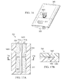
Figure 17A is a cross-sectional view of an uncured foam member in a mold tool, according to another embodiment of present application; and -
Figure 17B is a cross-sectional view of an uncured foam member in a mold tool, taken along the section lines 17B- 17B, shown inFigure 17A . - While the system of the present application is susceptible to various modifications and alternative forms, specific embodiments thereof have been shown by way of example in the drawings and are herein described in detail. It should be understood, however, that the description herein of specific embodiments is not intended to limit the method to the particular forms disclosed, but on the contrary, the intention is to cover all modifications, equivalents, and alternatives falling within the spirit and scope of the application as defined by the appended claims.
- Illustrative embodiments of the system of the present application are described below. In the interest of clarity, not all features of an actual implementation are described in this specification. It will of course be appreciated that in the development of any such actual embodiment, numerous implementation-specific decisions must be made to achieve the developer's specific goals, such as compliance with system-related and business-related constraints, which will vary from one implementation to another. Moreover, it will be appreciated that such a development effort might be complex and time-consuming but would nevertheless be a routine undertaking for those of ordinary skill in the art having the benefit of this disclosure.
- In the specification, reference may be made to the spatial relationships between various components and to the spatial orientation of various aspects of components as the devices are depicted in the attached drawings. However, as will be recognized by those skilled in the art after a complete reading of the present application, the devices, members, apparatuses, etc. described herein may be positioned in any desired orientation. Thus, the use of terms such as "above," "below," "upper," "lower," or other like terms to describe a spatial relationship between various components or to describe the spatial orientation of aspects of such components should be understood to describe a relative relationship between the components or a spatial orientation of aspects of such components, respectively, as the device described herein may be oriented in any desired direction.
- Referring to
Figure 2 , anaircraft 201 is illustrated.Aircraft 201 includesmain rotor blades 203, afuselage 209, alanding gear 207, and awing 211.Aircraft 201 further includes atail boom assembly 212, which is an assembly of atail boom 214, atail fin 213, anelevator 301, andtail rotor blades 205.Elevator 301 functions to provide pitch control during flight ofaircraft 201.Elevator 301 is illustrated and described herein as an embodiment of a foam stiffened structure. Further, it should be appreciated thatelevator 301 is simply one example of a foam stiffened structure that can be manufactured in accordance with the method of the present application. For example, a variety of structures onaircraft 201 may be manufactured in accordance with the method of the present application. For example,main rotor blade 203,tail rotor blade 205,wing 211,tail boom 214,tail fin 213, andfuselage 209 are all parts that may be manufactured in accordance with the method of the present application, so as to be stiffened by a molded foam member. Furthermore,aircraft 201 is merely exemplary of the wide variety of vehicles that may have foam stiffened structures formed from the method of the present application. For example, other exemplary vehicles may include fixed wing aircraft, boats, ships, automobiles, and skateboards, to name a few. - Referring now to
Figures 3-5 , a righthand side elevator 301 is illustrated. For clarity, the left hand side elevator is not shown, but in the illustrated embodiment, the left hand side elevator is a mirror image of the righthand side elevator 301.Elevator 301 includes afoam member 311 and askin 307. In the preferred embodiment,foam member 311 is molded in a tool. In a subsequent operation,skin 307 is preferably formed by placing uncured composite material ontofoam member 311, such thatfoam member 311 acts as a tooled surface for the composite material. The composite material is subsequently cured to become arigid skin 307. In an alternative embodiment,skin 307 is formed on a unique tooled surface and then cured. In such an embodiment,foam member 311 is formed by using theskin 307 as a tool by allowing the foam to expand and form inside theskin 307, thereby allowingskin 307 to act as a tool for the foam. In another alternative embodiment,skin 307 is not formed from a composite material, but rather thin sheet metal, or other semi-rigid material. In such an embodiment, the thin sheet metal is formed and bonded tofoam member 311, such thatfoam member 311 acts partly as tool by dictating final surface contour location of the sheet metal. In the illustrated embodiment,skin 307 includes anupper airfoil surface 315 and alower airfoil surface 313. - Further,
elevator 301 may include aninboard rib 303, anoutboard rib 305, and a trailingedge member 309.Inboard rib 303,outboard rib 305, and trailingedge member 309 are exemplary of members that may be formed integrally withfoam member 311, or assembled tofoam member 311 in an assembly operation subsequent to the formation offoam member 311.Inboard rib 303,outboard rib 305, and trailingedge member 311 can be formed from any conventional manufacturing operation, such as machining, molding, casting, injection molding, compression molding, to name a few. Further, an adhesive can be used to promote a bond between any of theskin 307,foam member 311,inboard rib 303,outboard rib 305, and trailingedge member 309. -
Foam member 311 provides structural stiffness toelevator 301.Skin 307 preferably comprise a plurality of reinforcing fibers disposed in a polymeric matrix. As discussed further herein,skin 307 is preferably placed ontofoam member 311 as a plurality of uncured composite plies, and then later cured to form a rigid composite laminate. It should be appreciated thatskin 307 can be formed from a variety of fiber and resin systems. It should also be appreciated that the specific composite material, or sheet metal, is implementation specific. For example, carbon fiber may be desirable in one application, while fiberglass fiber may be desirable in another application. - The molded
foam member 311 is preferably formed with a pourable and expandable structural foam in a mold, as discussed further herein. The moldedfoam member 311 is configured to provide the structural integrity toelevator 301 in a wide variety of geometries and contours. Curing ofskin 307 may require pressure, such as autoclave curing pressure, for proper curing. As such,foam member 311 is configured to provide structural resistance to the pressure so as to preserve the desired surface geometry ofskin 307.Foam member 311 is configured to be isotropic, thus the isotropic properties offoam member 311 allow it to retain structural integrity in a wide variety of geometries and contours. - Referring now to
Figure 6A , amethod 601 for manufacturing a foam stiffened structure, such aselevator 301, is schematically illustrated. Astep 603 ofmethod 601 includes fabricatinginboard rib 303,outboard rib 305, and trailingedge member 309, which may be included in some embodiments ofelevator 301. As discussed further herein, any ofinboard rib 303,outboard rib 305, and trailingedge member 309 maybe located in the mold during the manufacturing offoam member 311. - A
process 605 ofmethod 601 includes fabricatingfoam member 311. Referring now also toFigure 6B ,process 605 is schematically illustrated in further detail. Astep 613 ofprocess 605 includes manufacturing a mold for whichfoam member 311 is formed within. - Referring now also to
Figures 7A and 7B , amold 701 is illustrated.Mold 701 preferably includes afirst member 701 and asecond member 703.Mold 701 also includes acavity 707 formed partly in each of thefirst member 701 and asecond member 703. It should be appreciated thatmold 701 may be divided up into any number of separate members.Cavity 707 represents the desired geometry offoam member 311. A release agent is preferably applied to the interior ofcavity 707 in order to promote the release and removal offoam member 311 from themold 701. - A
step 615 ofprocess 605 includes creating afoam mixture 807. Referring now also toFigures 8-10 , the foam system used in the creation offoam member 311 is preferably a urethane foam system that expands to fillcavity 707 ofmold 701. Upon curing, the foam is preferably rigid and flexible, while having a relatively low density. The preferred foam system is a polyisocyanurate pour foam system marketed under the name of Stepanfoam BX 450, by the Stepan Chemical Company. It should be fully appreciated that other foam systems may be used in the molding offoam member 311. The Stepanfoam BX 450 includes two separate resin components, namely a resin T (70% by weight) 805 and a resin R (30% by weight) 803. The desired weight amounts ofresin T 805 andresin R 803 are measured and poured into acontainer 801. Theresin T 805 andresin R 803 are mechanically agitated to form ahomogenous mixture 807. Amixer 901 is used in rotation in order to mixresin T 805 andresin R 803 to formmixture 807.Mixer 901 includes ashaft 903, theshaft 903 being configured to be driven by a drill motor, or the like.Mixer 901 may include a plurality of blades located on afirst blade disc 905 and asecond blade disc 907. In the preferred embodiment,mixer 901 is rotated at 3500 revolutions per minute for 10-15 seconds when mixingresin T 805 andresin R 803 to formmixture 807. - The total weight amount of
mixture 807 is at least partially dependent upon the desired density and the volume offoam member 311. For example, because density is the relationship of mass per unit volume, the desired density offoam member 311 at least partially dictates the weight amount ofmixture 807. However, a portion of themixture 807 may escape from withincavity 707, which may affect the final density determination offoam member 311. - A
step 617 ofprocess 605 includes pouringfoam mixture 807 intocavity 707. Once the mixing instep 615 is complete, it is preferred thatmixture 807 is poured intocavity 707mold 701 as quickly as possible. - A
step 619 includes controlling expansion offoam mixture 807 incavity 707. Referring toFigure 11 , one embodiment ofstep 619 is illustrated. As shown inFigure 11 ,foam mixture 807 is allowed to "free rise" withincavity 707 so as to formfoam member 311 at a "free rise" density. In the "free-rise" embodiment, a density of approximately 8.0 pounds/ft3 and less can be achieved. The "free rise" embodiment offoam member 311 may be particularly desirable when the geometry and contours offoam member 311 are relatively simple. This is because the exposed surface would require a cutting or shaving operation to trim the exposed surface offoam member 311 to the desired contour. As shown inFigure 11 , a "free rise" embodiment includes allowingfoam mixture 807 to expand and polymerize without constraint. Expansion and polymerization offoam mixture 807 allows any volatiles to escape during the polymerization stage, and also to facilitate complete homogeneous fill ofcavity 707. The polymerization stage is the expansion from a chemical reaction of thefoam mixture 807. - Referring now also to
Figure 12 , another embodiment ofstep 619 includes using a "captive process" to tailor the density offoam member 311. The captive process involves using alid member 709 to generate pressure withincavity 707, thus inhibiting the expansion offoam mixture 807 during polymerization.Lid member 709 includes one ormore openings mixture 807. The size and number ofopenings foam member 311. In one embodiment, theopenings lid member 709 are sized to create afoam member 311 having a density of approximately 12-16 pounds/ft3. However, this size and quantity ofopenings foam member 311 of lower/higher density, respectively. The expected operational loading ofelevator 101 is a factor that may contribute to the customization of the density offoam member 311. The density offoam member 311 can be customized in accordance with the desired structural strength offoam member 311. - Referring now also to
Figures 13A and 13B , another embodiment ofstep 619 includes selectively positioninglid member 709 to create volumes of different densities. For example, a first volume having a density of D1 is created by selectively positioninglid member 709 by alocator tool 713.Locator tool 713 is configured to selectively positionlid member 709 as desired position. In the illustrated embodiment,lid member 709 has asingle opening 711a in order to produce a density of D1. It should be appreciated that density D1 can also be produced by decreasing the size ofopenings locator tool 713 is repositioned and another batch offoam mixture 807 is introduced so that a second volume is built between the first volume andlid member 709. In the illustrated embodiment, the second volume has a density D2 which is less than density D1 due to the use of both ventingopenings foam member 311 can be fully customized in accordance with the predicted loading offoam member 311 in a specific implementation. For example, the inboard portion ofelevator 301 may experience higher loading than the outboard portion, as such, it may be desirable forfoam member 301 to have a higher density, thus higher strength, near the inboard portion. It should be appreciated that even thoughFigure 13B is illustrated with regard to first and second volumes having densities of D1 and D2, step 619 may involve creating any number of volumes having a variety of densities. Further, the number of volumes and densities is implementation specific. For example, if the foam stiffened structure is a large wing on an aircraft, the foam stiffened wing may have a foam member with a dozen different volumes of varying densities. - Referring now also to
Figures 14A and 14B , another embodiment ofprocess 605 includes locating aform 1401 incavity 707 so as to create a void 1403 infoam member 311. The inclusion of void 1403 infoam member 311 may be particularly desirable for routing wiring, or other system components, throughfoam member 311. Moreover, void 1403 may also be desirable to reduce the weight offoam member 311. In one embodiment,form 1401 may be a rigid tool that is removed fromfoam member 311. In another embodiment,form 1401 is a structure that forms a bond withfoam member 311 and integral withfoam member 311. In such an embodiment,form 1401 acts as a fly-away tool in thatform 1401 dictates the geometry of void 1703, andform 1401 also remains withfoam member 311. It should be appreciated that the geometry and size ofvoid 1403 is implementation specific and may take on a wide variety of configurations. - Referring now also to
Figure 15 , another embodiment ofprocess 605 includes incorporating components intocavity 707 ofmold 701 so that such components are integral tofoam member 311. For example,inboard rib 303,outboard rib 305, and trailingedge member 309 can be located incavity 707 prior to the introduction offoam mixture 807. Asfoam mixture 807 expands and polymerizes,foam member 311 becomes integral withinboard rib 303,outboard rib 305, and trailingedge member 309. In such an embodiment, anaperture 1501 inoutboard rib 305 is configured to allow the escape of volatiles during expansion offoam mixture 807, similar to ventopenings - Referring now also to
Figures 17A and 17B , another embodiment ofprocess 605 includes incorporating arib 1701 intocavity 707 ofmold 701 so thatrib 1701 is integral tofoam member 311. For example,rib 1701 can be located chord-wise incavity 707 prior to the introduction offoam mixture 807. In one embodiment, an aperture inrib 1701 functions as a pour opening forfoam mixture 807, as well as a vent opening to allow volatiles to escape during expansion offoam mixture 807. However, venting throughrib 1701 may be accomplished in a variety of ways, such as through a gap betweenrib 1701 andform 1401. In such an embodiment,foam member 311 is formed in multiple steps, similar to the procedure described above in regard toFigures 13A and 13B . However, in contrast to thelid member 709 shown inFigures 13A and 13B ,rib 1701 is integral withfoam member 311.Rib 1701 can be used to provide supplemental structural support inelevator 301. In the illustrated embodiment,rib 1701 is located approximately mid-span, but it should be appreciated thatrib 1701 may be located in a variety of locations along the span of thefoam member 311. Further, it should be appreciated that even thoughFigures 17A and 17B are illustrated withform 1401 and void 1403, these are optional features such that some embodiments may not includeform 1401 and void 1403. In another alternative embodiment,rib 1701 is introduced after a first part offoam member 311 is formed inmold 701. In such an embodiment,rib 1701 may be "L" shaped in order to facilitate mating ofrib 1701 to the first part offoam member 311. It should be appreciated that even though only asingle rib 1701 is illustrated, one embodiment includes a plurality ofribs 1701 spaced throughfoam member 311. - Referring again to
Figure 6B ,process 605 continues with astep 621 for curingfoam member 311. A full cure offoam member 311 is preferred beforefoam member 311 is removed frommold 701. The full cure is achieved by first allowing thefoam member 311 to remain withinmold 701 for at least 24 hours after the expanding of thefoam mixture 807 withinmold 701. Thereafter, themold 701, withfoam member 311 remaining therein, is cured approximately between 350° F and 375° F for approximately two hours. It should be appreciated that alternative foam systems may require different curing requirements. It is preferred thatfoam member 311 andmold 701 are cooled to 150° F or below, before demolding. Astep 623 includesdemolding foam member 311. Demolding foam member includes removingfoam member 311 frommold 701. Demolding offoam member 311 may require pliable tools to facilitate separation of thefoam member 311 from withincavity 707. - Referring again to
Figure 6A ,method 601 continues with astep 607 for applying skin material tofoam member 311. Oncefoam member 311 is removed frommold 701 instep 623 ofprocess 605, then skin material forskin 307 can be applied tofoam member 311 in a manufacturing process. The geometry and contours offoam member 307 are accurate to a high tolerance because of being molded inmold tool 703. As such,foam member 311 is configured to act as a "fly-away tool" such that it not only acts as a tooling surface forskin 307 during assembly ofelevator 301, but also remains withelevator 301 during operation of the aircraft. - In one embodiment of
elevator 301, a structural bond exists betweenskin 307 andfoam member 311 such that shearing loads are transferred betweenskin 307 andfoam member 311 through the structural bond. In such an embodiment, the bond can be formed from the resin in the composite skin. The structural bonding can also be created or supplemented with an adhesive layer located betweenfoam member 311 andskin 307. In an alternative embodiment, a release material may be applied to prevent a structural bond betweenskin 307 andfoam member 311. - In the preferred embodiment,
step 607 includes applying uncured composite material ontofoam member 311. It should be appreciated that the composite manufacturing process may take on a wide variety of processes becauseskin 307 may be formed from a wide variety of composite fiber/resin systems, or from metallic materials. Referring now also toFigure 16 , in one exemplary embodiment afiber placement machine 1601 is used to apply tape strips of composite material in a certain configuration. Alternative embodiments can employ any number of composite manufacturing techniques known in the art.Foam member 311 acts as a tool by dictating the geometry ofskin 307. Becausefoam member 311 was formed inmold 701, the geometry and contours are highly accurate. As such,foam member 311 acts as a high tolerance support ofskin 307. - A
step 611 ofmethod 601 includesfinal assembly elevator 301. Ifinboard rib 303,outboard rib 305, and trailingedge member 309 are not already integrated withfoam member 311, then step 611 includes assembling these parts withfoam member 311 andskin 307. Step 611 can include assembling any other parts and performing final finish toelevator 301. - Still referring to
Figure 6A ,skin 307 is cured in astep 609 ofmethod 601.Skin 307, while onfoam member 311, may be vacuum bagged and cured in accordance with one of a variety of conventional composite curing processes. In some embodiments, such as whenskin 307 is simply a metal sheet, curing of the skin itself is not required. However, ifskin 307 is a metal sheet, an adhesive may be used between the metal sheet andfoam member 311, as such; the adhesive may require heat and pressure for curing. - The system of the present application provides significant advantages, including: (1) providing a stiffness producing foam member in a composite structure that can be molded in a variety of geometries and contours; (2) providing a stiffness producing foam member in a composite structure that can withstand autoclave curing pressure; (3) providing a stiffness producing foam member in a composite structure, the density of the foam member being selectively tailored; (4) providing a stiffness producing foam member in a composite structure that provides tooled support for a skin, such that the foam member not only provides structural stiffness, but also a tooling surface for the skin; and (5) providing a stiffness producing foam member in a structure, the foam member having a plurality of volumes of varying densities so that the strength/weight of the foam member is optimized for the predicted loading.
- The particular embodiments disclosed above are illustrative only, as the application may be modified and practiced in different but equivalent manners apparent to those skilled in the art having the benefit of the teachings herein. Furthermore, no limitations are intended to the details of construction or design herein shown, other than as described in the claims below. It is therefore evident that the particular embodiments disclosed above may be altered or modified and all such variations are considered within the scope and spirit of the application. Accordingly, the protection sought herein is as set forth in the claims below. It is apparent that a system with significant advantages has been described and illustrated. Although the system of the present application is shown in a limited number of forms, it is not limited to just these forms, but is amenable to various changes and modifications without departing from the spirit thereof.
Claims (15)
- An aircraft structure (301), comprising:a foam member (311), the foam member having an outer molded surface; anda skin member (307) located at least partially around the outer molded surface of the foam member;wherein the outer molded surface of the foam member (311) is a tooling surface for the skin member during assembly of the structure, andwherein the foam member is molded to comprise a first foam volume having a first density D1 and a second foam volume having a second density D2.
- The structure according to claim 1, wherein the structure comprises a plurality of different volumes having a plurality of different densities and wherein the structure has a specified implementation, wherein the densities of the volumes are selected based on the predicted loading of the structure expected in the specified implementation.
- The structure of claim 1 or claim 2, where the structure is an elevator (301), and wherein an inboard portion of the elevator has a higher density than an outboard portion of the elevator.
- The structure according to any preceding claim, wherein the skin is selected from a composite material and a metallic material, and/or wherein the foam member has a side portion left exposed such that the skin member only partially envelopes the foam member.
- The structure according to claim 1 or any of claims 2 to 4, wherein the skin member is a composite skin member and wherein the structure does not comprise an adhesive between the skin member and the foam member such that a structural bond is formed between the outer molded surface and a surface of the skin member from resin within the skin member.
- The structure according to claim 1 or any of claims 2 to 5, wherein the skin (307) is an airfoil shape and/or wherein the structure is an airfoil member for an aircraft.
- A method of making a composite aircraft structure, comprising:molding an at least partially cured foam member (311) comprising a first foam volume having a first density D1 and a second foam volume having a second density D2;laying up an uncured composite skin (307) onto an outer surface of the foam member such that the foam member acts as a tool for the uncured composite skin; andcuring the composite skin while foam member supports the portion of the composite skin.
- The method according to claim 7, wherein, the step of molding comprises:introducing a foam mixture (807) into a mold (701) having an interior cavity (707) which resembles a desired shape of the foam member;using a lid member (709) to restrict the expansion of the foam mixture, wherein the lid member is selectively positioned to create the first foam volume having the first density D1 and the second foam volume having the second density D2.
- The method according to claim 8 further comprising:using a locator tool (713) to selectively position the lid member (709) at a desired position to create the first foam volume;allowing the first foam volume to expand and polymerize;using the locator tool (713) to reposition the lid member (709) to a second desired position to create the second foam volume.
- The method according to any one of claims 8-9 further comprising using one or more vent openings (711a, 711b) in the lid member (709) to control the density of the first and second foam volumes.
- The method of claim 10, wherein the lid member (709) comprises two vent openings (711a, 711b), and the method comprises using one of the vent openings to control the density of the first foam volume, and using both of the vent openings to control the density of the second foam volume.
- The method according to any one of claims 7-11, wherein the step of laying up an uncured composite skin onto an outer surface of the foam member is achieved with a fiber placement machine.
- The method according to any one of claims 7-12, wherein the step of molding an at least partially cured foam member further comprises:locating a rib (303, 305, 1701) within the mold.
- The method according to any one of claims 7-13, wherein the method does not comprise use of an adhesive between the skin and the foam member, and wherein a structural bond is formed between the outer surface of the foam member and the composite skin from resin in the composite skin.
- The method according to any one of claims 7-14, wherein the step of molding comprises molding the structure to comprise a plurality of different volumes having a plurality of different densities, wherein the structure has a specified implementation, and wherein the densities of the volumes are selected based on the predicted loading of the structure expected in the specified implementation.
Applications Claiming Priority (3)
| Application Number | Priority Date | Filing Date | Title |
|---|---|---|---|
| US41045810P | 2010-11-05 | 2010-11-05 | |
| US13/224,532 US20120114897A1 (en) | 2010-11-05 | 2011-09-02 | Foam Stiffened Structure and Method of Making the Same |
| EP20110186041 EP2450275A1 (en) | 2010-11-05 | 2011-10-20 | Foam stiffened structure and method of making the same |
Related Parent Applications (1)
| Application Number | Title | Priority Date | Filing Date |
|---|---|---|---|
| EP20110186041 Division EP2450275A1 (en) | 2010-11-05 | 2011-10-20 | Foam stiffened structure and method of making the same |
Publications (3)
| Publication Number | Publication Date |
|---|---|
| EP2818404A1 true EP2818404A1 (en) | 2014-12-31 |
| EP2818404B1 EP2818404B1 (en) | 2016-01-13 |
| EP2818404B2 EP2818404B2 (en) | 2018-11-14 |
Family
ID=44946981
Family Applications (2)
| Application Number | Title | Priority Date | Filing Date |
|---|---|---|---|
| EP14164626.5A Not-in-force EP2818404B2 (en) | 2010-11-05 | 2011-10-20 | Method of making a foam stiffened structure |
| EP20110186041 Ceased EP2450275A1 (en) | 2010-11-05 | 2011-10-20 | Foam stiffened structure and method of making the same |
Family Applications After (1)
| Application Number | Title | Priority Date | Filing Date |
|---|---|---|---|
| EP20110186041 Ceased EP2450275A1 (en) | 2010-11-05 | 2011-10-20 | Foam stiffened structure and method of making the same |
Country Status (4)
| Country | Link |
|---|---|
| US (2) | US20120114897A1 (en) |
| EP (2) | EP2818404B2 (en) |
| CN (1) | CN102556334B (en) |
| CA (1) | CA2756119C (en) |
Cited By (1)
| Publication number | Priority date | Publication date | Assignee | Title |
|---|---|---|---|---|
| US10967966B2 (en) | 2017-07-28 | 2021-04-06 | Airbus Helicopters | Method of fabricating a rotor blade filler body, and a rotor blade filler body comprising at least one cellular assembly having closed cells |
Families Citing this family (30)
| Publication number | Priority date | Publication date | Assignee | Title |
|---|---|---|---|---|
| US9511445B2 (en) * | 2014-12-17 | 2016-12-06 | Aeroprobe Corporation | Solid state joining using additive friction stir processing |
| US9511446B2 (en) | 2014-12-17 | 2016-12-06 | Aeroprobe Corporation | In-situ interlocking of metals using additive friction stir processing |
| US9266191B2 (en) * | 2013-12-18 | 2016-02-23 | Aeroprobe Corporation | Fabrication of monolithic stiffening ribs on metallic sheets |
| US8632850B2 (en) | 2005-09-26 | 2014-01-21 | Schultz-Creehan Holdings, Inc. | Friction fabrication tools |
| US20130071604A1 (en) * | 2011-09-16 | 2013-03-21 | Annexair Inc. | Composite panel, a composite panel with an edge band, and method of applying and manufacturing the same |
| US9149999B2 (en) | 2012-10-30 | 2015-10-06 | Bell Helicopter Textron Inc. | Method of repairing, splicing, joining, machining, and stabilizing honeycomb core using pourable structural foam and a structure incorporating the same |
| US20140119930A1 (en) * | 2012-10-30 | 2014-05-01 | Bell Helicopter Textron Inc. | Method of Repairing, Splicing, Joining, Machining, and Stabilizing Honeycomb Core Using Pourable Structural Foam and a Structure Incorporating the Same |
| US9597826B2 (en) | 2012-10-30 | 2017-03-21 | Bell Helicopter Textron Inc. | Method of repairing, splicing, joining, machining, and stabilizing honeycomb core using pourable structural foam and a structure incorporating the same |
| US9333684B2 (en) * | 2012-10-30 | 2016-05-10 | Bell Helicopter Textron Inc. | Method of repairing, splicing, joining, machining, and stabilizing honeycomb core using pourable structural foam and a structure incorporating the same |
| ES2623044T3 (en) * | 2012-11-22 | 2017-07-10 | Airbus Operations S.L. | Method of manufacturing a highly integrated structure including leading and trailing edge ribs for an aircraft lift surface |
| KR20140147931A (en) * | 2013-06-19 | 2014-12-31 | 주식회사 제이에스영테크 | Wing for unmanned aerial vehicles and manufacturing method of the same |
| US9757883B2 (en) | 2014-09-25 | 2017-09-12 | Bell Helicopter Textron Inc. | Joining structural members using foam |
| US9849656B2 (en) * | 2014-10-13 | 2017-12-26 | Bell Helicopter Textron Inc. | Method of repairing a core stiffened structure |
| CN104494844B (en) * | 2014-12-25 | 2016-09-14 | 深圳市博尔创意文化发展有限公司 | A kind of composite wing front and rear edge eyelid covering manufacturing process |
| KR20170129202A (en) * | 2015-03-16 | 2017-11-24 | 로저스코포레이션 | METHOD FOR MANUFACTURING POLYMER FOAM COMPOSITE MATERIAL, POLYMER FOAM COMPOSITE PRODUCED BY THE SAME, AND PRODUCTION THEREOF |
| WO2017136941A1 (en) | 2016-02-09 | 2017-08-17 | Bauer Hockey Ltd. | Athletic gear or other devices comprising post-molded expandable components |
| CN108146652A (en) * | 2016-12-06 | 2018-06-12 | 成都凯迪精工科技有限责任公司 | A kind of aspect ratio is more than 9 times of rudder face manufacturing method |
| US10633976B2 (en) | 2017-07-25 | 2020-04-28 | Bell Helicopter Textron Inc. | Methods of customizing, manufacturing, and repairing a rotor blade using additive manufacturing processes |
| AU2018359514C1 (en) | 2017-10-31 | 2021-05-27 | MELD Manufacturing Corporation | Solid-state additive manufacturing system and material compositions and structures |
| US10933971B2 (en) * | 2017-12-08 | 2021-03-02 | Wing Aviation Llc | Injection molded wing structure for aerial vehicles |
| CN109774199B (en) * | 2019-01-17 | 2021-07-13 | 江苏恒神股份有限公司 | Forming method of carbon fiber composite rudder-shaped structure |
| US11427350B2 (en) | 2019-01-31 | 2022-08-30 | Textron Innovations Inc. | Methods of forming and assembling a rotor blade using additive manufacturing processes |
| US11298899B2 (en) | 2019-06-24 | 2022-04-12 | Textron Innovations Inc. | System and method for repairing a composite structure |
| CN110510145A (en) * | 2019-08-30 | 2019-11-29 | 中国民用航空飞行学院 | A three-beam composite wing integral structure and its forming process method |
| US12054237B2 (en) * | 2020-03-06 | 2024-08-06 | The Boeing Company | Skinned cell structures and methods of producing the same |
| CN113183487B (en) * | 2021-05-28 | 2024-10-11 | 常州启赋安泰复合材料科技有限公司 | A helicopter tail beam mold and a method for preparing an integrally formed composite tail beam component |
| EP4370301A2 (en) * | 2021-07-12 | 2024-05-22 | Imagine Aero Inc. | Manufacturing methods and related structures, for example useful in airframes and other structures |
| CN114104326B (en) * | 2021-12-03 | 2024-04-26 | 西北工业大学 | A method for producing a drone |
| CN116118995B (en) * | 2022-11-11 | 2025-08-26 | 北京航天长征飞行器研究所 | A flying skateboard main structure |
| CN120134657B (en) * | 2025-02-11 | 2025-12-09 | 北京玻钢院复合材料有限公司 | Co-curing forming method for wing tip winglet with double-curvature laminated plate structure |
Citations (5)
| Publication number | Priority date | Publication date | Assignee | Title |
|---|---|---|---|---|
| US3873654A (en) * | 1973-03-05 | 1975-03-25 | Robert G Smith | Process of forming a rigid foam airfoil section |
| GB2120621A (en) * | 1982-05-20 | 1983-12-07 | Heruport Limited | Aircraft wing |
| US4671471A (en) * | 1984-05-21 | 1987-06-09 | Mitchell Wing, Inc. | Foam reinforced aluminum wing structure |
| EP0671250A1 (en) * | 1994-03-08 | 1995-09-13 | Basf Aktiengesellschaft | Method of manufacturing foam articles with layers of different densities |
| EP1582328A1 (en) * | 2002-11-11 | 2005-10-05 | Sunstar Giken Kabushiki Kaisha | Method and apparatus for foam molding |
Family Cites Families (34)
| Publication number | Priority date | Publication date | Assignee | Title |
|---|---|---|---|---|
| GB1040948A (en) | 1962-07-26 | 1966-09-01 | Dow Chemical Co | Improved airfoil structure and method of manufacture |
| US3258861A (en) * | 1962-07-31 | 1966-07-05 | United Shoe Machinery Corp | Polyurethane footwear heels |
| US3809733A (en) * | 1968-11-06 | 1974-05-07 | Ici Ltd | Production of double layer laminates |
| DE2117070C3 (en) * | 1971-04-07 | 1975-09-18 | Sued-West Chemie Gmbh, 7910 Neu- Ulm | Component made from a polyurethane foam layer and at least one cover layer connected to it |
| US3960631A (en) * | 1974-08-30 | 1976-06-01 | Whirlpool Corporation | Method of making a liner construction |
| US4181287A (en) * | 1978-06-26 | 1980-01-01 | Owens-Corning Fiberglas Corporation | Molding apparatus for rigid foam pipe insulation |
| DE2905701A1 (en) * | 1979-02-15 | 1980-08-28 | Arthur Wybiral | Moulding model aeroplane parts in split moulds - by placing into first split mould in succession glass fibre blank, foamed polystyrene core and glass fibre blank |
| US4525228A (en) * | 1982-08-13 | 1985-06-25 | United Kingdom Atomic Energy Authority | Method of winding on foam mandrel |
| DE3438602A1 (en) | 1984-10-20 | 1986-04-24 | Robbe Modellsport Gmbh, 6424 Grebenhain | Process for producing a model component and model component produced according to this process |
| US4687691A (en) * | 1986-04-28 | 1987-08-18 | United Technologies Corporation | Honeycomb spliced multilayer foam core aircraft composite parts and method for making same |
| US4828325A (en) | 1986-05-16 | 1989-05-09 | University Of Tennessee Research Corporation | Method of making a custom fitted composite foamed cushion, a preform kit and the resultant product of the process |
| US5042968A (en) * | 1989-11-02 | 1991-08-27 | United Technologies Corporation | Propeller blade subassembly and method for making a propeller blade subassembly |
| US5096384A (en) * | 1990-07-27 | 1992-03-17 | The Marley Cooling Tower Company | Plastic fan blade for industrial cooling towers and method of making same |
| US5071331A (en) * | 1990-08-27 | 1991-12-10 | Cabot Safety Corporation | Mold for foam products |
| US5087511A (en) * | 1990-08-31 | 1992-02-11 | General Electric Company | Composite element having a variable density core |
| US5173227A (en) * | 1990-12-06 | 1992-12-22 | United Technologies Corporation | In-situ molding of fiber reinforced composites to net shape |
| US5112663A (en) * | 1991-04-22 | 1992-05-12 | General Dynamics Corporation, Convair Division | Method of manufacturing composite structures |
| US5773121A (en) | 1994-07-29 | 1998-06-30 | Isorca Inc. | Syntactic foam core incorporating honeycomb structure for composites |
| DE19649132C2 (en) * | 1996-11-27 | 1999-09-02 | Daimler Chrysler Aerospace | Nose for an aerodynamic surface and method of making it |
| US6630093B1 (en) * | 1999-08-21 | 2003-10-07 | Ronald D. Jones | Method for making freeform-fabricated core composite articles |
| GB0001267D0 (en) | 2000-01-21 | 2000-03-08 | West Edward V | Method of composting and container therefor |
| JP4465929B2 (en) * | 2001-07-05 | 2010-05-26 | 株式会社プライムポリマー | Method for producing foam of thermoplastic resin composition |
| US6818279B2 (en) | 2001-08-22 | 2004-11-16 | Parat Automotive Schonenbach Gmbh & Co. Kg | Foldable convertible top and method of making same |
| US6625830B2 (en) | 2001-10-02 | 2003-09-30 | Neal Lampel | Wheelchair cushion |
| DE10231830A1 (en) | 2002-07-12 | 2004-01-22 | Röhm GmbH & Co. KG | Foam with compacted surface |
| US7732044B2 (en) * | 2002-09-04 | 2010-06-08 | Foam Matrix, Inc. | Foam core-surface reinforced article and method |
| DE10357656A1 (en) * | 2003-12-10 | 2005-07-07 | Mtu Aero Engines Gmbh | Method for producing gas turbine components and component for a gas turbine |
| US7531058B2 (en) * | 2005-02-24 | 2009-05-12 | The Boeing Company | Reinforced rampdown for composite structural member and method for same |
| ES2319152B1 (en) * | 2007-07-17 | 2010-01-11 | Fco.Javier Garcia Castro | PROCEDURE FOR THE MANUFACTURE OF WIND SHOES. |
| US7879276B2 (en) * | 2007-11-08 | 2011-02-01 | The Boeing Company | Foam stiffened hollow composite stringer |
| US8221084B2 (en) * | 2008-02-28 | 2012-07-17 | Textron Innovations Inc. | Single-piece propeller and method of making |
| US8540921B2 (en) | 2008-11-25 | 2013-09-24 | The Boeing Company | Method of forming a reinforced foam-filled composite stringer |
| ATE537060T1 (en) * | 2009-05-27 | 2011-12-15 | Eurocopter Deutschland | ROTOR BLADE AS A FIBER COMPOSITE PROFILE BODY AND METHOD FOR PRODUCING IT USING RESIN INJECTION TECHNOLOGY |
| US20110293914A1 (en) * | 2010-05-27 | 2011-12-01 | Maurer Myron J | Shaped foam composite article |
-
2011
- 2011-09-02 US US13/224,532 patent/US20120114897A1/en not_active Abandoned
- 2011-10-20 EP EP14164626.5A patent/EP2818404B2/en not_active Not-in-force
- 2011-10-20 EP EP20110186041 patent/EP2450275A1/en not_active Ceased
- 2011-10-20 CA CA2756119A patent/CA2756119C/en active Active
- 2011-11-02 CN CN201110364708.1A patent/CN102556334B/en not_active Expired - Fee Related
-
2016
- 2016-06-28 US US15/195,501 patent/US11097507B2/en active Active
Patent Citations (5)
| Publication number | Priority date | Publication date | Assignee | Title |
|---|---|---|---|---|
| US3873654A (en) * | 1973-03-05 | 1975-03-25 | Robert G Smith | Process of forming a rigid foam airfoil section |
| GB2120621A (en) * | 1982-05-20 | 1983-12-07 | Heruport Limited | Aircraft wing |
| US4671471A (en) * | 1984-05-21 | 1987-06-09 | Mitchell Wing, Inc. | Foam reinforced aluminum wing structure |
| EP0671250A1 (en) * | 1994-03-08 | 1995-09-13 | Basf Aktiengesellschaft | Method of manufacturing foam articles with layers of different densities |
| EP1582328A1 (en) * | 2002-11-11 | 2005-10-05 | Sunstar Giken Kabushiki Kaisha | Method and apparatus for foam molding |
Non-Patent Citations (1)
| Title |
|---|
| "Moldless Composite Homebuilt Sandwich Aircraft Construction 3rd Edition", 1 September 1983 (1983-09-01), Mojave, CA 93501, USA, pages 1 - 3-21, XP055083730, Retrieved from the Internet <URL:http://mbfab.com/aircraft/terfcd/TERF CD/Rutan Plans/Main/MOLDCOMP/MCHSAC.PDF> [retrieved on 20131014] * |
Cited By (1)
| Publication number | Priority date | Publication date | Assignee | Title |
|---|---|---|---|---|
| US10967966B2 (en) | 2017-07-28 | 2021-04-06 | Airbus Helicopters | Method of fabricating a rotor blade filler body, and a rotor blade filler body comprising at least one cellular assembly having closed cells |
Also Published As
| Publication number | Publication date |
|---|---|
| US20160303818A1 (en) | 2016-10-20 |
| EP2818404B2 (en) | 2018-11-14 |
| US20120114897A1 (en) | 2012-05-10 |
| US11097507B2 (en) | 2021-08-24 |
| CN102556334A (en) | 2012-07-11 |
| CN102556334B (en) | 2016-06-01 |
| CA2756119C (en) | 2016-08-02 |
| CA2756119A1 (en) | 2012-05-05 |
| EP2818404B1 (en) | 2016-01-13 |
| EP2450275A1 (en) | 2012-05-09 |
Similar Documents
| Publication | Publication Date | Title |
|---|---|---|
| US11097507B2 (en) | Foam stiffened structure and method of making the same | |
| EP2635431B1 (en) | Moldable fly-away tool structure system | |
| US9015941B2 (en) | Method of repairing honeycomb core using pourable structural foam | |
| US9149999B2 (en) | Method of repairing, splicing, joining, machining, and stabilizing honeycomb core using pourable structural foam and a structure incorporating the same | |
| CA2908200C (en) | Method of repairing a core stiffened structure | |
| EP2727697B1 (en) | Method of stabilizing honeycomb core using pourable structural foam | |
| CA2831103C (en) | Method of repairing, splicing, joining, machining, and stabilizing honeycomb core using pourable structural foam and a structure incorporating the same | |
| EP2727698B1 (en) | Method of machining and stabilizing a core member with cells using pourable structural foam | |
| US9550334B2 (en) | Method of repairing a core stiffened structure |
Legal Events
| Date | Code | Title | Description |
|---|---|---|---|
| PUAI | Public reference made under article 153(3) epc to a published international application that has entered the european phase |
Free format text: ORIGINAL CODE: 0009012 |
|
| 17P | Request for examination filed |
Effective date: 20140414 |
|
| AC | Divisional application: reference to earlier application |
Ref document number: 2450275 Country of ref document: EP Kind code of ref document: P |
|
| AK | Designated contracting states |
Kind code of ref document: A1 Designated state(s): AL AT BE BG CH CY CZ DE DK EE ES FI FR GB GR HR HU IE IS IT LI LT LU LV MC MK MT NL NO PL PT RO RS SE SI SK SM TR |
|
| 17Q | First examination report despatched |
Effective date: 20150121 |
|
| RIC1 | Information provided on ipc code assigned before grant |
Ipc: B29C 44/10 20060101ALI20150911BHEP Ipc: B64C 1/06 20060101ALI20150911BHEP Ipc: B64C 3/20 20060101AFI20150911BHEP Ipc: B29C 44/08 20060101ALI20150911BHEP Ipc: B29C 44/02 20060101ALI20150911BHEP Ipc: B64C 3/24 20060101ALI20150911BHEP Ipc: B32B 5/18 20060101ALI20150911BHEP |
|
| GRAP | Despatch of communication of intention to grant a patent |
Free format text: ORIGINAL CODE: EPIDOSNIGR1 |
|
| GRAS | Grant fee paid |
Free format text: ORIGINAL CODE: EPIDOSNIGR3 |
|
| INTG | Intention to grant announced |
Effective date: 20151026 |
|
| GRAA | (expected) grant |
Free format text: ORIGINAL CODE: 0009210 |
|
| AC | Divisional application: reference to earlier application |
Ref document number: 2450275 Country of ref document: EP Kind code of ref document: P |
|
| AK | Designated contracting states |
Kind code of ref document: B1 Designated state(s): AL AT BE BG CH CY CZ DE DK EE ES FI FR GB GR HR HU IE IS IT LI LT LU LV MC MK MT NL NO PL PT RO RS SE SI SK SM TR |
|
| REG | Reference to a national code |
Ref country code: GB Ref legal event code: FG4D |
|
| REG | Reference to a national code |
Ref country code: CH Ref legal event code: EP |
|
| REG | Reference to a national code |
Ref country code: IE Ref legal event code: FG4D |
|
| REG | Reference to a national code |
Ref country code: AT Ref legal event code: REF Ref document number: 770313 Country of ref document: AT Kind code of ref document: T Effective date: 20160215 |
|
| REG | Reference to a national code |
Ref country code: DE Ref legal event code: R096 Ref document number: 602011022744 Country of ref document: DE |
|
| REG | Reference to a national code |
Ref country code: LT Ref legal event code: MG4D |
|
| REG | Reference to a national code |
Ref country code: NL Ref legal event code: MP Effective date: 20160113 |
|
| REG | Reference to a national code |
Ref country code: AT Ref legal event code: MK05 Ref document number: 770313 Country of ref document: AT Kind code of ref document: T Effective date: 20160113 |
|
| PG25 | Lapsed in a contracting state [announced via postgrant information from national office to epo] |
Ref country code: NL Free format text: LAPSE BECAUSE OF FAILURE TO SUBMIT A TRANSLATION OF THE DESCRIPTION OR TO PAY THE FEE WITHIN THE PRESCRIBED TIME-LIMIT Effective date: 20160113 |
|
| PG25 | Lapsed in a contracting state [announced via postgrant information from national office to epo] |
Ref country code: ES Free format text: LAPSE BECAUSE OF FAILURE TO SUBMIT A TRANSLATION OF THE DESCRIPTION OR TO PAY THE FEE WITHIN THE PRESCRIBED TIME-LIMIT Effective date: 20160113 Ref country code: NO Free format text: LAPSE BECAUSE OF FAILURE TO SUBMIT A TRANSLATION OF THE DESCRIPTION OR TO PAY THE FEE WITHIN THE PRESCRIBED TIME-LIMIT Effective date: 20160413 Ref country code: GR Free format text: LAPSE BECAUSE OF FAILURE TO SUBMIT A TRANSLATION OF THE DESCRIPTION OR TO PAY THE FEE WITHIN THE PRESCRIBED TIME-LIMIT Effective date: 20160414 Ref country code: HR Free format text: LAPSE BECAUSE OF FAILURE TO SUBMIT A TRANSLATION OF THE DESCRIPTION OR TO PAY THE FEE WITHIN THE PRESCRIBED TIME-LIMIT Effective date: 20160113 Ref country code: FI Free format text: LAPSE BECAUSE OF FAILURE TO SUBMIT A TRANSLATION OF THE DESCRIPTION OR TO PAY THE FEE WITHIN THE PRESCRIBED TIME-LIMIT Effective date: 20160113 |
|
| PG25 | Lapsed in a contracting state [announced via postgrant information from national office to epo] |
Ref country code: PT Free format text: LAPSE BECAUSE OF FAILURE TO SUBMIT A TRANSLATION OF THE DESCRIPTION OR TO PAY THE FEE WITHIN THE PRESCRIBED TIME-LIMIT Effective date: 20160513 Ref country code: LV Free format text: LAPSE BECAUSE OF FAILURE TO SUBMIT A TRANSLATION OF THE DESCRIPTION OR TO PAY THE FEE WITHIN THE PRESCRIBED TIME-LIMIT Effective date: 20160113 Ref country code: SE Free format text: LAPSE BECAUSE OF FAILURE TO SUBMIT A TRANSLATION OF THE DESCRIPTION OR TO PAY THE FEE WITHIN THE PRESCRIBED TIME-LIMIT Effective date: 20160113 Ref country code: RS Free format text: LAPSE BECAUSE OF FAILURE TO SUBMIT A TRANSLATION OF THE DESCRIPTION OR TO PAY THE FEE WITHIN THE PRESCRIBED TIME-LIMIT Effective date: 20160113 Ref country code: AT Free format text: LAPSE BECAUSE OF FAILURE TO SUBMIT A TRANSLATION OF THE DESCRIPTION OR TO PAY THE FEE WITHIN THE PRESCRIBED TIME-LIMIT Effective date: 20160113 Ref country code: IS Free format text: LAPSE BECAUSE OF FAILURE TO SUBMIT A TRANSLATION OF THE DESCRIPTION OR TO PAY THE FEE WITHIN THE PRESCRIBED TIME-LIMIT Effective date: 20160513 Ref country code: PL Free format text: LAPSE BECAUSE OF FAILURE TO SUBMIT A TRANSLATION OF THE DESCRIPTION OR TO PAY THE FEE WITHIN THE PRESCRIBED TIME-LIMIT Effective date: 20160113 Ref country code: LT Free format text: LAPSE BECAUSE OF FAILURE TO SUBMIT A TRANSLATION OF THE DESCRIPTION OR TO PAY THE FEE WITHIN THE PRESCRIBED TIME-LIMIT Effective date: 20160113 |
|
| REG | Reference to a national code |
Ref country code: DE Ref legal event code: R026 Ref document number: 602011022744 Country of ref document: DE |
|
| PLBI | Opposition filed |
Free format text: ORIGINAL CODE: 0009260 |
|
| REG | Reference to a national code |
Ref country code: FR Ref legal event code: PLFP Year of fee payment: 6 |
|
| PG25 | Lapsed in a contracting state [announced via postgrant information from national office to epo] |
Ref country code: EE Free format text: LAPSE BECAUSE OF FAILURE TO SUBMIT A TRANSLATION OF THE DESCRIPTION OR TO PAY THE FEE WITHIN THE PRESCRIBED TIME-LIMIT Effective date: 20160113 Ref country code: DK Free format text: LAPSE BECAUSE OF FAILURE TO SUBMIT A TRANSLATION OF THE DESCRIPTION OR TO PAY THE FEE WITHIN THE PRESCRIBED TIME-LIMIT Effective date: 20160113 |
|
| PLAX | Notice of opposition and request to file observation + time limit sent |
Free format text: ORIGINAL CODE: EPIDOSNOBS2 |
|
| 26 | Opposition filed |
Opponent name: EVONIK ROEHM GMBH Effective date: 20161013 |
|
| PG25 | Lapsed in a contracting state [announced via postgrant information from national office to epo] |
Ref country code: CZ Free format text: LAPSE BECAUSE OF FAILURE TO SUBMIT A TRANSLATION OF THE DESCRIPTION OR TO PAY THE FEE WITHIN THE PRESCRIBED TIME-LIMIT Effective date: 20160113 Ref country code: SM Free format text: LAPSE BECAUSE OF FAILURE TO SUBMIT A TRANSLATION OF THE DESCRIPTION OR TO PAY THE FEE WITHIN THE PRESCRIBED TIME-LIMIT Effective date: 20160113 Ref country code: RO Free format text: LAPSE BECAUSE OF FAILURE TO SUBMIT A TRANSLATION OF THE DESCRIPTION OR TO PAY THE FEE WITHIN THE PRESCRIBED TIME-LIMIT Effective date: 20160113 Ref country code: SK Free format text: LAPSE BECAUSE OF FAILURE TO SUBMIT A TRANSLATION OF THE DESCRIPTION OR TO PAY THE FEE WITHIN THE PRESCRIBED TIME-LIMIT Effective date: 20160113 |
|
| PG25 | Lapsed in a contracting state [announced via postgrant information from national office to epo] |
Ref country code: BE Free format text: LAPSE BECAUSE OF FAILURE TO SUBMIT A TRANSLATION OF THE DESCRIPTION OR TO PAY THE FEE WITHIN THE PRESCRIBED TIME-LIMIT Effective date: 20160113 |
|
| PG25 | Lapsed in a contracting state [announced via postgrant information from national office to epo] |
Ref country code: BG Free format text: LAPSE BECAUSE OF FAILURE TO SUBMIT A TRANSLATION OF THE DESCRIPTION OR TO PAY THE FEE WITHIN THE PRESCRIBED TIME-LIMIT Effective date: 20160413 Ref country code: SI Free format text: LAPSE BECAUSE OF FAILURE TO SUBMIT A TRANSLATION OF THE DESCRIPTION OR TO PAY THE FEE WITHIN THE PRESCRIBED TIME-LIMIT Effective date: 20160113 |
|
| PLBB | Reply of patent proprietor to notice(s) of opposition received |
Free format text: ORIGINAL CODE: EPIDOSNOBS3 |
|
| REG | Reference to a national code |
Ref country code: CH Ref legal event code: PL |
|
| REG | Reference to a national code |
Ref country code: IE Ref legal event code: MM4A |
|
| PG25 | Lapsed in a contracting state [announced via postgrant information from national office to epo] |
Ref country code: LI Free format text: LAPSE BECAUSE OF NON-PAYMENT OF DUE FEES Effective date: 20161031 Ref country code: CH Free format text: LAPSE BECAUSE OF NON-PAYMENT OF DUE FEES Effective date: 20161031 |
|
| PG25 | Lapsed in a contracting state [announced via postgrant information from national office to epo] |
Ref country code: LU Free format text: LAPSE BECAUSE OF NON-PAYMENT OF DUE FEES Effective date: 20161020 |
|
| REG | Reference to a national code |
Ref country code: FR Ref legal event code: PLFP Year of fee payment: 7 |
|
| PG25 | Lapsed in a contracting state [announced via postgrant information from national office to epo] |
Ref country code: IE Free format text: LAPSE BECAUSE OF NON-PAYMENT OF DUE FEES Effective date: 20161020 |
|
| PG25 | Lapsed in a contracting state [announced via postgrant information from national office to epo] |
Ref country code: HU Free format text: LAPSE BECAUSE OF FAILURE TO SUBMIT A TRANSLATION OF THE DESCRIPTION OR TO PAY THE FEE WITHIN THE PRESCRIBED TIME-LIMIT; INVALID AB INITIO Effective date: 20111020 |
|
| PG25 | Lapsed in a contracting state [announced via postgrant information from national office to epo] |
Ref country code: MC Free format text: LAPSE BECAUSE OF FAILURE TO SUBMIT A TRANSLATION OF THE DESCRIPTION OR TO PAY THE FEE WITHIN THE PRESCRIBED TIME-LIMIT Effective date: 20160113 Ref country code: CY Free format text: LAPSE BECAUSE OF FAILURE TO SUBMIT A TRANSLATION OF THE DESCRIPTION OR TO PAY THE FEE WITHIN THE PRESCRIBED TIME-LIMIT Effective date: 20160113 Ref country code: MT Free format text: LAPSE BECAUSE OF NON-PAYMENT OF DUE FEES Effective date: 20161031 Ref country code: MK Free format text: LAPSE BECAUSE OF FAILURE TO SUBMIT A TRANSLATION OF THE DESCRIPTION OR TO PAY THE FEE WITHIN THE PRESCRIBED TIME-LIMIT Effective date: 20160113 |
|
| APAH | Appeal reference modified |
Free format text: ORIGINAL CODE: EPIDOSCREFNO |
|
| APBM | Appeal reference recorded |
Free format text: ORIGINAL CODE: EPIDOSNREFNO |
|
| APBP | Date of receipt of notice of appeal recorded |
Free format text: ORIGINAL CODE: EPIDOSNNOA2O |
|
| APBU | Appeal procedure closed |
Free format text: ORIGINAL CODE: EPIDOSNNOA9O |
|
| RIN2 | Information on inventor provided after grant (corrected) |
Inventor name: MISHRA, SAVANKAR Inventor name: EVANS, WILLIAM Inventor name: THIAGARAJAN, RAMESH Inventor name: MIKEL, MIKE Inventor name: CHRIS, MARK |
|
| PUAH | Patent maintained in amended form |
Free format text: ORIGINAL CODE: 0009272 |
|
| STAA | Information on the status of an ep patent application or granted ep patent |
Free format text: STATUS: PATENT MAINTAINED AS AMENDED |
|
| REG | Reference to a national code |
Ref country code: FR Ref legal event code: PLFP Year of fee payment: 8 |
|
| PG25 | Lapsed in a contracting state [announced via postgrant information from national office to epo] |
Ref country code: TR Free format text: LAPSE BECAUSE OF FAILURE TO SUBMIT A TRANSLATION OF THE DESCRIPTION OR TO PAY THE FEE WITHIN THE PRESCRIBED TIME-LIMIT Effective date: 20160113 Ref country code: AL Free format text: LAPSE BECAUSE OF FAILURE TO SUBMIT A TRANSLATION OF THE DESCRIPTION OR TO PAY THE FEE WITHIN THE PRESCRIBED TIME-LIMIT Effective date: 20160113 |
|
| 27A | Patent maintained in amended form |
Effective date: 20181114 |
|
| AK | Designated contracting states |
Kind code of ref document: B2 Designated state(s): AL AT BE BG CH CY CZ DE DK EE ES FI FR GB GR HR HU IE IS IT LI LT LU LV MC MK MT NL NO PL PT RO RS SE SI SK SM TR |
|
| REG | Reference to a national code |
Ref country code: DE Ref legal event code: R102 Ref document number: 602011022744 Country of ref document: DE |
|
| P01 | Opt-out of the competence of the unified patent court (upc) registered |
Effective date: 20230602 |
|
| PGFP | Annual fee paid to national office [announced via postgrant information from national office to epo] |
Ref country code: GB Payment date: 20231027 Year of fee payment: 13 |
|
| PGFP | Annual fee paid to national office [announced via postgrant information from national office to epo] |
Ref country code: IT Payment date: 20231023 Year of fee payment: 13 Ref country code: FR Payment date: 20231025 Year of fee payment: 13 Ref country code: DE Payment date: 20231027 Year of fee payment: 13 |
|
| REG | Reference to a national code |
Ref country code: DE Ref legal event code: R119 Ref document number: 602011022744 Country of ref document: DE |
|
| GBPC | Gb: european patent ceased through non-payment of renewal fee |
Effective date: 20241020 |
|
| PG25 | Lapsed in a contracting state [announced via postgrant information from national office to epo] |
Ref country code: DE Free format text: LAPSE BECAUSE OF NON-PAYMENT OF DUE FEES Effective date: 20250501 |
|
| PG25 | Lapsed in a contracting state [announced via postgrant information from national office to epo] |
Ref country code: GB Free format text: LAPSE BECAUSE OF NON-PAYMENT OF DUE FEES Effective date: 20241020 |
|
| PG25 | Lapsed in a contracting state [announced via postgrant information from national office to epo] |
Ref country code: FR Free format text: LAPSE BECAUSE OF NON-PAYMENT OF DUE FEES Effective date: 20241031 |
|
| PG25 | Lapsed in a contracting state [announced via postgrant information from national office to epo] |
Ref country code: IT Free format text: LAPSE BECAUSE OF NON-PAYMENT OF DUE FEES Effective date: 20241020 |