EP2818363A1 - Camera device, camera system, and camera calibration method - Google Patents
Camera device, camera system, and camera calibration method Download PDFInfo
- Publication number
- EP2818363A1 EP2818363A1 EP13751150.7A EP13751150A EP2818363A1 EP 2818363 A1 EP2818363 A1 EP 2818363A1 EP 13751150 A EP13751150 A EP 13751150A EP 2818363 A1 EP2818363 A1 EP 2818363A1
- Authority
- EP
- European Patent Office
- Prior art keywords
- camera
- image
- calibration
- calibration object
- mark
- Prior art date
- Legal status (The legal status is an assumption and is not a legal conclusion. Google has not performed a legal analysis and makes no representation as to the accuracy of the status listed.)
- Granted
Links
Images




Classifications
-
- G—PHYSICS
- G06—COMPUTING OR CALCULATING; COUNTING
- G06T—IMAGE DATA PROCESSING OR GENERATION, IN GENERAL
- G06T7/00—Image analysis
- G06T7/80—Analysis of captured images to determine intrinsic or extrinsic camera parameters, i.e. camera calibration
-
- H—ELECTRICITY
- H04—ELECTRIC COMMUNICATION TECHNIQUE
- H04N—PICTORIAL COMMUNICATION, e.g. TELEVISION
- H04N17/00—Diagnosis, testing or measuring for television systems or their details
- H04N17/002—Diagnosis, testing or measuring for television systems or their details for television cameras
-
- G—PHYSICS
- G06—COMPUTING OR CALCULATING; COUNTING
- G06T—IMAGE DATA PROCESSING OR GENERATION, IN GENERAL
- G06T2207/00—Indexing scheme for image analysis or image enhancement
- G06T2207/10—Image acquisition modality
- G06T2207/10004—Still image; Photographic image
-
- G—PHYSICS
- G06—COMPUTING OR CALCULATING; COUNTING
- G06T—IMAGE DATA PROCESSING OR GENERATION, IN GENERAL
- G06T2207/00—Indexing scheme for image analysis or image enhancement
- G06T2207/20—Special algorithmic details
- G06T2207/20092—Interactive image processing based on input by user
-
- G—PHYSICS
- G06—COMPUTING OR CALCULATING; COUNTING
- G06T—IMAGE DATA PROCESSING OR GENERATION, IN GENERAL
- G06T2207/00—Indexing scheme for image analysis or image enhancement
- G06T2207/30—Subject of image; Context of image processing
- G06T2207/30244—Camera pose
-
- G—PHYSICS
- G06—COMPUTING OR CALCULATING; COUNTING
- G06T—IMAGE DATA PROCESSING OR GENERATION, IN GENERAL
- G06T2207/00—Indexing scheme for image analysis or image enhancement
- G06T2207/30—Subject of image; Context of image processing
- G06T2207/30248—Vehicle exterior or interior
- G06T2207/30252—Vehicle exterior; Vicinity of vehicle
Definitions
- the present invention relates to a camera device, a camera system and a camera calibration method for calibration of an angle of a camera mounted on a vehicle.
- a camera system that enables, by using a camera mounted on a rear side of a vehicle, to display an image behind the vehicle, where it is hard for a driver to view, on a display unit inside the vehicle.
- a method by adjusting a difference between an assumed image capturing a subject whose position information is known and an actual image of the subject actually taken by the camera, to obtain parameters for calibration of a camera mounting position (for example, see Patent Document 1 and Patent Document 2).
- a camera device includes: a camera mounted on a predetermined position of a vehicle and configured to take an image including a mark provided outside the vehicle; an image superimposing unit configured to generate a superimposed image by superimposing a calibration object having a position adjustment part and a rotation adjustment part on the image taken by the camera; and a calculation unit configured to calculate, based on a position of the calibration object after being shifted in the superimposed image such that an end or a center of the mark meets the position adjustment part and a part of the mark other than the end or the center overlaps the rotation adjustment part, parameters relative to a pan angle, a tilt angle and a roll angle for calibration of a camera mounting position.
- the calculation unit when an instruction to shift the calibration object in horizontal, vertical and rotational directions is detected, shifts a display position of the calibration object on the superimposed image according to the instruction.
- the position adjustment part has a circular shape.
- the rotation adjustment part includes a plurality of parallel lines adjacent to the position adjustment part.
- the calculation unit controls to display the image taken by the camera at least when a parking mode is selected and when a camera calibration mode is selected.
- the camera device wherein the calculation unit, when the camera calibration mode is selected, controls the image superimposing unit to superimpose the calibration object on the image taken by the camera.
- the camera device wherein the calculation unit, when the parking mode is selected, controls the image superimposing unit to superimpose a predicted track of the vehicle on the image taken by the camera.
- the camera device wherein a marker is provided on the center of the mark and the calibration object is shifted such that the position adjustment part meets the marker.
- a camera device includes: a camera mounted on a predetermined position of a vehicle and configured to take an image including a mark provided outside the vehicle; an image superimposing unit configured to generate a superimposed image by superimposing a calibration object having calibrations for a rough indication of a shift amount on the image taken by the camera; and a calculation unit configured to calculate, based on a position of the calibration object after being shifted in the superimposed image such that the mark and all or a part of the calibration object roughly overlap with each other, parameters relative to a pan angle, a tilt angle and a roll angle for calibration of a camera mounting position.
- intervals of the calibrations of the calibration object correspond to a shift amount by predetermined times of operations to shift the calibration object.
- a camera device includes: a camera mounted on a predetermined position of a vehicle and configured to take an image including a mark provided outside the vehicle; an image superimposing unit configured to generate a superimposed image by superimposing a calibration object having one end adjustment part and the other end adjustment part having markers in a predetermined width on the image taken by the camera; and a calculation unit configured to calculate, based on a position of the calibration object after being shifted in the superimposed image such that one end and the other end of the mark respectively fit in the predetermined width of the marker of the one end adjustment part and the other end adjustment part, parameters relative to a pan angle, a tilt angle and a roll angle for calibration of a camera mounting position.
- a camera device includes: a camera mounted on a predetermined position of a vehicle and configured to take an image including a mark provided outside the vehicle; an image superimposing unit configured to generate a superimposed image by superimposing a calibration object having both end adjustment parts and calibrations for adjusting a rotation axis on the image taken by the camera; and a calculation unit configured to calculate, based on a position of the calibration object after being shifted in the superimposed image such that, after the mark and the calibrations become roughly parallel to one another, each end of the mark roughly meets the respective both end adjustment parts, parameters relative to a pan angle, a tilt angle and a roll angle for calibration of a camera mounting position.
- a camera device includes: a camera mounted on a predetermined position of a vehicle and configured to take an image including a mark provided outside the vehicle; an image superimposing unit configured to generate a superimposed image by superimposing a calibration object having an upper line, a lower line, a left line and a right line on the image taken by the camera; and a calculation unit configured to calculate, based on a position of the calibration object when the upper line, the lower line, the left line and the right line are separately shifted such that the mark fits in an area surrounded by the upper line, the lower line, the left line and the right line, parameters relative to a pan angle, a tilt angle and a roll angle for calibration of a camera mounting position.
- a camera calibration method includes: a step to take an image including a mark provided outside a vehicle by a camera mounted on a predetermined position of the vehicle; a step to generate a superimposed image by superimposing a calibration object having a position adjustment part and a rotation adjustment part on the image taken by the camera; and a step to calculate, based on a position of the calibration object after being shifted in the superimposed image such that an end or a center of the mark meets the position adjustment part and a part other than the end or the center of the mark overlaps the rotation adjustment part, parameters relative to a pan angle, a tilt angle and a roll angle for calibration of a camera mounting position.
- a camera system includes: a camera mounted on a predetermined position of a vehicle and configured to take an image including a mark provided outside the vehicle; an image superimposing unit configured to generate a superimposed image by superimposing a calibration object having a position adjustment part and a rotation adjustment part on the image taken by the camera; a display unit provided inside the vehicle and configured to display the superimposed image; an instruction unit configured to instruct the calibration object to shift a display position of the calibration object on the superimposed image; and a calculation unit configured to calculate, based on the position of the calibration object when an end or a center of the mark meets the position adjustment part and a part other than the end or the center of the mark overlaps the rotation adjustment part, parameters relative to a pan angle, a tilt angle and a roll angle for calibration of a camera mounting position.
- a calibration operation of the camera is simplified and a time necessary for the calibration is shortened.
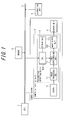
- FIG. 1 is a block diagram illustrating an example of a configuration of a system when a camera system according to the embodiment of the present invention is mounted on a vehicle (for example, a car).
- the system mounted on the vehicle includes a camera system 1, a CPU 2 for controlling the entire system, a bus 3, an instruction unit 5 and a sensor 6.
- the camera system 1 includes a camera calibration device (camera device) 10 and a display unit 4.
- the camera calibration device 10 includes a camera 11 and a calibration operation device 12.
- the calibration operation device 12 includes an image processing unit 121, an image superimposing unit 122, an image output unit 123, a CPU 124 and a storage unit 125.
- the camera 11 has an image sensor such as CMOS or CCD for converting the light of a subject entering through a lens into an electric signal and generating an image of the subject.
- the camera 11 is mounted on a predetermined position of the vehicle.
- FIG. 17 is a diagram illustrating the vehicle having the camera 11 mounted thereon. According to the present embodiment, as illustrated in FIG. 17 , the camera 11 is mounted near a bumper 44 on the rear side of a vehicle 100 to take an image behind the vehicle 100.
- An area A in the figure represents an area captured by the camera 11.
- the display unit 4 when a user selects a parking mode, displays an image generated by the camera system 1.
- the parking mode assists smooth parking by displaying, on the display unit 4, an image in the area A behind the vehicle 100, where it is difficult for the user driving the vehicle 100 to view.
- a predicted track of the vehicle 100 may be superimposed on the image in the area A behind the vehicle 100, for assisting smoother parking.
- the image generated by the camera system 1 is displayed.
- the camera calibration mode by disposing an indicative subject or figure in the area A behind the vehicle 100, allows the user to calibrate a mounting position of the camera 11 by using an image of a mark taken by the camera 11.
- the camera calibration mode is used when the camera 11 is mounted on the vehicle 100 in a production line of the vehicle 100 or when the camera 11 is displaced due to vibrations of the vehicle 100. A detailed calibration method will be described below.
- the display unit 4 may display a route map to a destination obtained by a navigation system.
- the display unit 4 may display television obtained by a TV receiver.
- the instruction unit 5 serves as a user interface for adjustment of a position of the calibration object superimposed in the display unit 4.
- the instruction unit 5 may be operated to shift the calibration object in vertical, horizontal and rotational directions.
- the instruction unit 5 outputs an object shift signal obtained by an operation by the user to the CPU 124 via the bus 3.
- the instruction unit 5 outputs an adjustment end signal to the CPU 124 via the bus 3.
- the sensor 6 includes a speed sensor for detecting a moving speed of the vehicle, a gear sensor for detecting a position of a gear lever, and a steering angle sensor for detecting a steering angle.
- the sensor 6 outputs a sensor signal obtained from each sensor to the CPU 124 and the CPU 2 via the bus 3.
- the storage unit 125 stores a position coordinate of the camera 11 and a position coordinate of the mark as known values.
- the CPU 124 determines a display position of the calibration object based on the object shift signal obtained from the instruction unit 5 and instructs the image superimposing unit 122 to generate a superimposed image. Also, the CPU 124, upon receiving a calibration end instruction from the instruction unit 5, obtains the position coordinate of the calibration object at the end of the calibration and the position coordinates of the camera 11 and the mark stored in the storage unit 125, and then calculates, based on the position coordinates, calibration parameters (a pan angle, a tilt angle and a roll angle) for calibration of the mounting position of the camera 11. Moreover, the CPU 124 determines a display position of the predicted track of the vehicle 100 based on the sensor signal obtained from the sensor 6 and instructs the image superimposing unit 122 to generate the superimposed image.
- calibration parameters a pan angle, a tilt angle and a roll angle
- the image processing unit 121 generates a digital image by performing A/D conversion, noise reduction processing and image processing to the image taken by the camera 11 and outputs the digital image to the image superimposing unit 122.
- the image superimposing unit 122 based on the instruction by the CPU 124, generates the superimposed image by superimposing an image on a predetermined position of the digital image generated by the image processing unit 121 and outputs the superimposed image to the image output unit 123.
- the image to be superimposed is the calibration object used for calibration of the mounting position of the camera 11 or the predicted track to be followed by the vehicle 100 moving backward, for assisting parking.
- the image output unit 123 converts the superimposed image generated by the image superimposing unit 122 into a format (for example, NTSC) appropriate for a display device of the display unit 4 and outputs the converted superimposed image to the display unit 4.
- a format for example, NTSC
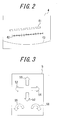
- FIG. 2 is a diagram illustrating an example of an image displayed on the display unit 4 when the user selects the parking mode.
- the display unit 4 displays a mark 41 and a calibration object 42.
- an edge of the bumper 43 is also displayed.
- the mark 41 is a subject or figure disposed at a predetermined distance (for example, 1m) from a rear end of the vehicle 100 when the vehicle 100 is accurately stopped at a predetermined parking position, and takes the shape of, for example, a rectangular plate or a white line drawn on a road. That is, when the camera 11 is mounted on a correct angle, a positional relationship between the vehicle 100 and the mark 41 is specified, thus the mark 41 taken by the camera 11 is always displayed at a specific position on the image displayed on the display unit 4.
- the instruction unit 5 may issue an instruction to shift the calibration object 42 to the mark 41. Thereby, the calibration parameters for specifying deviation of a mounting angle of the camera 11 may be obtained.
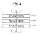
- FIG. 3 is a diagram illustrating an example of an outline view of the instruction unit 5.
- the instruction unit 5 includes an upward instruction unit 51, a left instruction unit 52, a downward instruction unit 53, a right instruction unit 54, a counterclockwise rotation instruction unit 55 and a clockwise rotation instruction unit 56, which may be mechanical switches provided near the display unit 4 inside the vehicle or objects displayed on a touch panel laminated on the display unit 4.
- the upward instruction unit 51 is used to shift the calibration object 42 upward and the left instruction unit 52 is used to shift the calibration object 42 in the left direction.
- the downward instruction unit 53 is used to shift the calibration object 42 downward and the right instruction unit 54 is used to shift the calibration object 42 in the right direction.
- the counterclockwise rotation instruction unit 55 is used to rotate the calibration object 42 counterclockwise and the clockwise rotation instruction unit 56 is used to rotate the calibration object 42 clockwise.
- the calibration object 42 upon a single pressing of the left instruction unit 52 or the right instruction unit 54, is shifted by the number of pixels equivalent to a shift amount of the image when an image taking direction of the camera 11 is directed by 0.5 degrees in a pan (horizontal) direction.
- the vertical (tilt) direction and a roll (rotational) direction are shifted by the number of pixels equivalent to a shift amount of the image when an image taking direction of the camera 11 is directed by 0.5 degrees in a pan (horizontal) direction.
- FIG. 4 is a flowchart illustrating the calibration operation of the camera by the camera system 1.
- FIG. 5 is a diagram illustrating images displayed on the display unit 4 in calibration operation of the camera.
- FIG. 5(a) illustrates a state when the left instruction unit 52 is pressed down and the calibration object 42 is shifted in the left direction.
- FIG. 5(b) illustrates a state when the upward instruction unit 51 is pressed down and the calibration object 42 is shifted upward.
- FIG. 5(c) illustrates a state when the counterclockwise rotation instruction unit 55 is pressed down and the calibration object 42 rotates counterclockwise.
- the calibration object 42 illustrated in FIGS. 2 and 5 has calibrations at regular intervals.
- the calibrations indicate an approximate shift amount and the intervals of the calibrations correspond to a predetermined number of shift operations of the calibration object.
- the intervals of the calibrations are defined as a moving distance when the left instruction unit 52 or the right instruction unit 54 is pressed down five times.
- the calibrations allow the user to obtain an approximate shift amount of the calibration object 42. For example, when the calibration object 42 is displaced relative to the mark 41 by one calibration in the right direction, the user may shift the calibration object 42 at once by one calibration in the left direction by continuously pressing down the left instruction unit 52 five times.
- the operation time may be shortened. The same applies not only in the horizontal (pan) direction but also the vertical (tilt) direction and the rotational (roll) direction. Examples are illustrated in a part of FIG. 6 .
- FIG. 6 is a diagram illustrating other examples of the calibration object 42 having the calibrations.
- the calibrations are provided in an approximately vertical direction and an approximately horizontal direction in a part (main part) of the calibration object 42 having no calibrations. This allows the user to obtain an approximate shift amount of the calibration object 42 in the vertical and horizontal directions.
- the calibrations are provided in the rotational direction at the main part. This allows the user to obtain an approximate shift amount of the calibration object 42 in the rotational direction as well as in the vertical and horizontal directions.
- grid calibrations may be provided at the main part.
- the calibrations are not limited to lines but may be notched as illustrated in FIG. 6(d) , for example.
- the calibration object 42 may have only steps. In this case, a distance between a leftmost step and a rightmost step is equal to a length of the mark 41.
- FIG. 7 is a diagram illustrating examples of the calibration object 42 having one end adjustment part and the other end adjustment part having markers with a predetermined width.
- the markers indicate that the calibration object 42 may be shift until one end and the other end of the mark 41 fit in the predetermined width between the markers of the one end adjustment part and the other end adjustment part.
- four large corner-shaped markers and four small corner-shaped markers are provided to allow for a rough positioning relative to the mark 41 by using the large corner-shaped markers and then an accurate positioning by using the small corner-shaped markers; that is, to allow for a two-step calibration that enables quick and highly accurate positioning relative to the mark 41.
- the markers may be provided at both ends of the calibration object 42 having the calibrations.
- the calibration object 42 is given some width in a short direction thereof. Therefore, when the calibration object 42 is largely displaced from the mark 41, the calibration object 42 may be roughly positioned relative to the mark 41 by referring to the width in the short direction. Thereby, in this case also, the calibration object 42 may be positioned quickly and accurately relative to the mark 41.
- the number of markers may be increased to have multiple markers such as four markers, each of which includes an outer line, a middle line and an inner line, such that the calibration object 42 is shifted to fit in an area surrounded by the markers.
- the outermost four markers allow for a rough positioning and the inner markers allow for more accurate positioning. Therefore, the calibration object 42 may be positioned quickly and accurately even when the calibration object 42 is largely displaced.
- the calibration parameter may be calculated when the calibration object 42 shifted toward the mark 41 does not completely overlap the mark 41, there has been no method to allow the user to know by how much error the calculation of the calibration parameter is not affected. Therefore, the width of the marker indicates a margin for error.
- the operation may end when the one end and the other end of the mark 41 fit between the one end adjustment part and the other end adjustment part of the marker having the predetermined width therebetween. Thereby, the time for adjustment may be shortened.
- FIG. 8 is a diagram illustrating an example of the calibration object 42 having the one end adjustment part and the rotational adjustment part.
- the one end adjustment part in the shape of a circle is shifted to one end portion of the mark 41.
- FIG. 8(b) illustrates a state when the one end portion of the mark 41 roughly overlaps the one end adjustment part of the calibration object 42.
- the calibration object 42 is rotated as illustrated by an arrow in FIG. 8(b) until the entire mark 41 except for the end portion thereof roughly overlaps the rotational adjustment part of the calibration object 42.
- FIG. 9 is a diagram illustrating an example of the calibration object 42 when the mark 41 has a marker.
- the mark 41 having a marker as illustrated in FIG. 9(a) , enables to use the calibration object 42 having a marker adjustment part and the rotation adjustment part.
- FIG. 9(b) illustrates a state when the marker of the mark 41 roughly meets the marker adjustment part of the calibration object 42.
- the calibration object 42 is rotated as indicated by arrows in FIG. 9(b) until the entire mark 41 except for the marker roughly overlaps the rotation adjustment part of the calibration object 42.
- FIG. 10 is a diagram illustrating an example of the calibration object 42 having both end adjustment parts and a plurality of parallel calibration lines for adjustment of a rotation axis.
- the calibration lines of the calibration object 42 is rotated until any of the calibration lines becomes parallel to the mark 41.
- the calibration object 42 rotates together with the calibration lines.
- FIG. 10(b) illustrates a state when the mark 41 is approximately parallel to one of the calibration lines of the calibration object 42.
- the calibration object 42 is shifted to the upper left until the both end adjustment parts of the calibration object 42 roughly meet both ends of the mark 41. Accordingly, since there is no need to rotate the calibration object 42 after shifting in the vertical and horizontal directions, the time for adjustment may be shortened.
- FIG. 11 is a diagram illustrating an example of the calibration object 42 having an upper line, a lower line, a left line and a right line.
- the upper line, the lower line, the left line and the right line are preliminarily displayed at four edges. Then, the upper line, the lower line, the left line and the right line are separately shifted such that the mark 41 fits in an area surrounded by all of these lines.
- FIG. 11(b) illustrates a state when the mark 41 fits in the area surrounded by the upper line, the lower line, the left line and the right line of the calibration object 42.
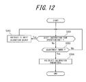
- FIG. 12 is a flowchart illustrating an operation of the CPU 124 in calibration operation of the camera 11.
- the CPU 124 receives the object shift signal from the instruction unit 5 (Yes at step S201)
- the CPU 124 instructs the image superimposing unit 122 to superimpose the image (step S202).
- the CPU 124 waits for the shift instruction from the instruction unit 5 until receiving an adjustment end signal from the instruction unit 5 (No at step S203).
- the CPU 124 calculates the calibration parameters (a pan angle, a tilt angle and a roll angle) (step S204).
- FIG. 13 is a diagram illustrating the calibration parameter calculation method and indicates a positional relationship between the camera 11 mounted on the vehicle 100 and the mark 41. Two ends of the mark 41 are denoted by P 1 and P 2 , respectively.
- a position of the camera 11 (an origin of a camera coordinate) is represented by (tx, ty, tz) in the world coordinate.
- a relative positional relationship viewed from the camera 11 may be represented in a camera coordinate system.
- the camera coordinate system may be represented by a parallel translation or rotational translation relative to the world coordinate system.
- FIG. 14 is a diagram illustrating rotational translation in the world coordinate system.
- a rotation about Zw as illustrated in FIG. 14(a) is referred to as the pan
- a rotation about Yw as illustrated in FIG. 14(b) is referred to as the roll
- a rotation about Xw as illustrated in FIG. 14(c) is referred to as the tilt.
- ⁇ , ⁇ and ⁇ represent a rotation angle of the pan (pan angle), a rotation angle of the roll (roll angle) and a rotation angle of the tilt (tilt angle), respectively
- P 1 represented by a coordinate (xw 1 , yw 1 , zw 1 ) in the world coordinate system may be represented by Formula (1) in the camera coordinate system.
- FIG. 15 is a diagram illustrating coordinates of the mark 41 in a camera image.
- the coordinates of the mark 41 may be obtained by shifting the calibration object as described above.
- a position of P 1 at the end of the mark 41 is represented by ( Xi , z i ) in a coordinate having a center point of the camera image as the origin, an image height h on a sensor surface of the camera 11 may be calculated from Formula (2) using a sensor pixel pitch d.
- h x i 2 + z i 2 ⁇ d
- a relationship between an incident angle ⁇ i on a lens and the image height h on the sensor surface may be represented by Formula (3) using a focal length f and distortion dist of the lens.
- Formula (3) h ⁇ f tan ⁇ i ⁇ 1 + dist
- FIG. 16 is a diagram illustrating coordinates of the both ends P 1 and P 2 of the mark 41 in the camera coordinate system.
- the incident angle ⁇ i on the camera 11 relative to the point P 1 may be calculated from Formula (4).
- ⁇ i tan - 1 ⁇ x ⁇ c 2 + z ⁇ c 2 y ⁇ c
- (xc 1 , yc 1 , zc 1 ) may be calculated from Formulas (6), (7) and (8) using the angle ⁇ i obtained from Formulas (2) and (3), and the angle ⁇ i calculated from Formula (5).
- the pan angle ⁇ , the roll angle ⁇ and the tilt angle ⁇ may be calculated from Formulas (1), (9), (10) and (11). That is, the CPU 124 may calculate the calibration parameters by obtaining two coordinates of the calibration object by satisfying the equalities (10) and (11).
- the image taken by the camera 11, after calculation of the calibration parameters by the CPU 124, is output being offset by an amount corresponding to the calibration parameters.
- the image superimposing unit 122 when the image superimposing unit 122 generates the superimposed image by superimposing the image of the predicted track or the like on the digital image generated by the image processing unit 121, the predicted track or the like is superimposed offset from its superimposing position prior to calculation of the calibration parameters. Therefore, a highly accurate predicted vehicle track may be displayed in parking, for example.
- the calibration object 42 in a first embodiment has calibrations for indicating the approximate shift amount.
- the calibration object 42 in a second embodiment has the one end adjustment part and the other end adjustment part having the markers at predetermined intervals.
- the calibration object 42 in a third embodiment has the one end adjustment part and the rotation adjustment part.
- the calibration object 42 in a fourth embodiment has the marker adjustment part and the rotation adjustment part.
- the calibration object 42 in a fifth embodiment has the both end adjustment parts and the calibrations for adjusting the rotation axis.
- the calibration object 42 in a sixth embodiment has the upper line, the lower line, the left line and the right line which are separately movable.
Landscapes
- Engineering & Computer Science (AREA)
- Multimedia (AREA)
- Health & Medical Sciences (AREA)
- Biomedical Technology (AREA)
- General Health & Medical Sciences (AREA)
- Signal Processing (AREA)
- Computer Vision & Pattern Recognition (AREA)
- Physics & Mathematics (AREA)
- General Physics & Mathematics (AREA)
- Theoretical Computer Science (AREA)
- Studio Devices (AREA)
- Closed-Circuit Television Systems (AREA)
- Length Measuring Devices By Optical Means (AREA)
- Mechanical Engineering (AREA)
Abstract
Description
- This application claims priority to and the benefit of Japanese Patent Application No.
2012-039416 filed on February 24, 2012 - The present invention relates to a camera device, a camera system and a camera calibration method for calibration of an angle of a camera mounted on a vehicle.
- There is known a camera system that enables, by using a camera mounted on a rear side of a vehicle, to display an image behind the vehicle, where it is hard for a driver to view, on a display unit inside the vehicle. For such a system, there is known a method, by adjusting a difference between an assumed image capturing a subject whose position information is known and an actual image of the subject actually taken by the camera, to obtain parameters for calibration of a camera mounting position (for example, see
Patent Document 1 and Patent Document 2). -
- Patent Document 1: Japanese Patent Laid-Open No.
2000-209577 - Patent Document 2: Japanese Patent Laid-Open No.
10-181447 - In obtaining the parameters for calibration of the camera mounting position, in order to adjust the difference between the assumed image and the actual image, it is necessary to shift the assumed image to overlap the actual image. However, there has been a problem that, because of a time lag between an instruction by a user to shift the assumed image and the shift of the assumed image, a calibration operation takes time when there are a plurality of instructions to shift the assumed image in vertical, horizontal and rotational directions.
- Accordingly, it is an object of the present invention, in consideration of such a problem, to provide a camera device, a camera system and a camera calibration method that may simplify a calibration operation of the camera and shorten a time necessary for calibration.
- In order to solve the above problem, a camera device according to one embodiment includes: a camera mounted on a predetermined position of a vehicle and configured to take an image including a mark provided outside the vehicle; an image superimposing unit configured to generate a superimposed image by superimposing a calibration object having a position adjustment part and a rotation adjustment part on the image taken by the camera; and a calculation unit configured to calculate, based on a position of the calibration object after being shifted in the superimposed image such that an end or a center of the mark meets the position adjustment part and a part of the mark other than the end or the center overlaps the rotation adjustment part, parameters relative to a pan angle, a tilt angle and a roll angle for calibration of a camera mounting position.
- The camera device according to one embodiment, wherein the calculation unit, when an instruction to shift the calibration object in horizontal, vertical and rotational directions is detected, shifts a display position of the calibration object on the superimposed image according to the instruction.
- The camera device according to one embodiment, wherein the position adjustment part has a circular shape.
- The camera device according to one embodiment, wherein the rotation adjustment part includes a plurality of parallel lines adjacent to the position adjustment part.
- The camera device according to one embodiment, wherein the calculation unit controls to display the image taken by the camera at least when a parking mode is selected and when a camera calibration mode is selected.
- The camera device according to one embodiment, wherein the calculation unit, when the camera calibration mode is selected, controls the image superimposing unit to superimpose the calibration object on the image taken by the camera.
- The camera device according to one embodiment, wherein the calculation unit, when the parking mode is selected, controls the image superimposing unit to superimpose a predicted track of the vehicle on the image taken by the camera.
- The camera device according to one embodiment, wherein a marker is provided on the center of the mark and the calibration object is shifted such that the position adjustment part meets the marker.
- A camera device according to one embodiment includes: a camera mounted on a predetermined position of a vehicle and configured to take an image including a mark provided outside the vehicle; an image superimposing unit configured to generate a superimposed image by superimposing a calibration object having calibrations for a rough indication of a shift amount on the image taken by the camera; and a calculation unit configured to calculate, based on a position of the calibration object after being shifted in the superimposed image such that the mark and all or a part of the calibration object roughly overlap with each other, parameters relative to a pan angle, a tilt angle and a roll angle for calibration of a camera mounting position.
- The camera device according to one embodiment, wherein intervals of the calibrations of the calibration object correspond to a shift amount by predetermined times of operations to shift the calibration object.
- A camera device according to one embodiment includes: a camera mounted on a predetermined position of a vehicle and configured to take an image including a mark provided outside the vehicle; an image superimposing unit configured to generate a superimposed image by superimposing a calibration object having one end adjustment part and the other end adjustment part having markers in a predetermined width on the image taken by the camera; and a calculation unit configured to calculate, based on a position of the calibration object after being shifted in the superimposed image such that one end and the other end of the mark respectively fit in the predetermined width of the marker of the one end adjustment part and the other end adjustment part, parameters relative to a pan angle, a tilt angle and a roll angle for calibration of a camera mounting position.
- A camera device according to one embodiment includes: a camera mounted on a predetermined position of a vehicle and configured to take an image including a mark provided outside the vehicle; an image superimposing unit configured to generate a superimposed image by superimposing a calibration object having both end adjustment parts and calibrations for adjusting a rotation axis on the image taken by the camera; and a calculation unit configured to calculate, based on a position of the calibration object after being shifted in the superimposed image such that, after the mark and the calibrations become roughly parallel to one another, each end of the mark roughly meets the respective both end adjustment parts, parameters relative to a pan angle, a tilt angle and a roll angle for calibration of a camera mounting position.
- A camera device according to one embodiment includes: a camera mounted on a predetermined position of a vehicle and configured to take an image including a mark provided outside the vehicle; an image superimposing unit configured to generate a superimposed image by superimposing a calibration object having an upper line, a lower line, a left line and a right line on the image taken by the camera; and a calculation unit configured to calculate, based on a position of the calibration object when the upper line, the lower line, the left line and the right line are separately shifted such that the mark fits in an area surrounded by the upper line, the lower line, the left line and the right line, parameters relative to a pan angle, a tilt angle and a roll angle for calibration of a camera mounting position.
- Moreover, in order to solve the above problem, a camera calibration method according to one embodiment includes: a step to take an image including a mark provided outside a vehicle by a camera mounted on a predetermined position of the vehicle; a step to generate a superimposed image by superimposing a calibration object having a position adjustment part and a rotation adjustment part on the image taken by the camera; and a step to calculate, based on a position of the calibration object after being shifted in the superimposed image such that an end or a center of the mark meets the position adjustment part and a part other than the end or the center of the mark overlaps the rotation adjustment part, parameters relative to a pan angle, a tilt angle and a roll angle for calibration of a camera mounting position.
- Further, in order to solve the above problem, a camera system according to one embodiment includes: a camera mounted on a predetermined position of a vehicle and configured to take an image including a mark provided outside the vehicle; an image superimposing unit configured to generate a superimposed image by superimposing a calibration object having a position adjustment part and a rotation adjustment part on the image taken by the camera; a display unit provided inside the vehicle and configured to display the superimposed image; an instruction unit configured to instruct the calibration object to shift a display position of the calibration object on the superimposed image; and a calculation unit configured to calculate, based on the position of the calibration object when an end or a center of the mark meets the position adjustment part and a part other than the end or the center of the mark overlaps the rotation adjustment part, parameters relative to a pan angle, a tilt angle and a roll angle for calibration of a camera mounting position.
- According to the embodiments, a calibration operation of the camera is simplified and a time necessary for the calibration is shortened.
-
-
FIG. 1 is a block diagram illustrating an example of a configuration of a system mounting a camera system according to one embodiment of the present invention. -
FIG. 2 is a block diagram illustrating an example of an image displayed on a display unit of the camera system according to one embodiment of the present invention. -
FIG. 3 is a block diagram illustrating an example of an outline view of an instruction unit of the camera system according to one embodiment of the present invention. -
FIG. 4 is a flowchart illustrating a calibration operation of a camera by the camera system according to one embodiment of the present invention. -
FIG. 5(a)-(c) are diagrams illustrating images displayed on the display unit in calibration operation of the camera by the camera system according to one embodiment of the present invention. -
FIG. 6(a)-(e) are diagrams illustrating examples of a calibration object having calibrations. -
FIG. 7(a)-(d) are diagrams illustrating examples of a calibration object having one end adjustment part and the other end adjustment part with markers in a predetermined width. -
FIG. 8(a) and (b) are diagrams illustrating an example of a calibration object having the one adjustment part and a rotation adjustment part. -
FIG. 9(a) and (b) are diagrams illustrating an example of a calibration object when a mark has a marker. -
FIG. 10(a) and (b) are diagrams illustrating an example of a calibration object having both end adjustment parts and the calibrations for adjustment of a rotation axis. -
FIG. 11(a) and (b) are diagrams illustrating an example of a calibration object having an upper line, a lower line, a left line and a right line. -
FIG. 12 is a flowchart illustrating an operation of a CPU in calibration operation of the camera by the camera system according to one embodiment of the present invention. -
FIG. 13 is a diagram illustrating a calibration parameter calculation method in calibration operation of the camera by the camera system according to one embodiment of the present invention. -
FIG. 14(a)-(c) are diagrams illustrating rotations in a world coordinate system. -
FIG. 15 is a diagram illustrating a camera image by the camera system according to one embodiment of the present invention. -
FIG. 16 is a diagram illustrating coordinates of both ends of the mark in a camera coordinate system. -
FIG. 17 is a diagram illustrating a vehicle having the camera mounted thereon. - Embodiments of the present invention will be described with reference to the accompanying drawings.
-
FIG. 1 is a block diagram illustrating an example of a configuration of a system when a camera system according to the embodiment of the present invention is mounted on a vehicle (for example, a car). As illustrate inFIG. 1 , the system mounted on the vehicle includes acamera system 1, a CPU 2 for controlling the entire system, a bus 3, aninstruction unit 5 and asensor 6. Thecamera system 1 includes a camera calibration device (camera device) 10 and adisplay unit 4. Thecamera calibration device 10 includes acamera 11 and acalibration operation device 12. Thecalibration operation device 12 includes animage processing unit 121, an imagesuperimposing unit 122, animage output unit 123, aCPU 124 and astorage unit 125. - The
camera 11 has an image sensor such as CMOS or CCD for converting the light of a subject entering through a lens into an electric signal and generating an image of the subject. Thecamera 11 is mounted on a predetermined position of the vehicle.FIG. 17 is a diagram illustrating the vehicle having thecamera 11 mounted thereon. According to the present embodiment, as illustrated inFIG. 17 , thecamera 11 is mounted near a bumper 44 on the rear side of avehicle 100 to take an image behind thevehicle 100. An area A in the figure represents an area captured by thecamera 11. - The
display unit 4, when a user selects a parking mode, displays an image generated by thecamera system 1. The parking mode assists smooth parking by displaying, on thedisplay unit 4, an image in the area A behind thevehicle 100, where it is difficult for the user driving thevehicle 100 to view. A predicted track of thevehicle 100 may be superimposed on the image in the area A behind thevehicle 100, for assisting smoother parking. - Also, when a camera calibration mode is selected by the user, the image generated by the
camera system 1 is displayed. The camera calibration mode, by disposing an indicative subject or figure in the area A behind thevehicle 100, allows the user to calibrate a mounting position of thecamera 11 by using an image of a mark taken by thecamera 11. The camera calibration mode is used when thecamera 11 is mounted on thevehicle 100 in a production line of thevehicle 100 or when thecamera 11 is displaced due to vibrations of thevehicle 100. A detailed calibration method will be described below. - When a navigation mode is selected by the user, the
display unit 4 may display a route map to a destination obtained by a navigation system. When a TV mode is selected, thedisplay unit 4 may display television obtained by a TV receiver. - The
instruction unit 5 serves as a user interface for adjustment of a position of the calibration object superimposed in thedisplay unit 4. Theinstruction unit 5 may be operated to shift the calibration object in vertical, horizontal and rotational directions. Theinstruction unit 5 outputs an object shift signal obtained by an operation by the user to theCPU 124 via the bus 3. When an adjustment operation ends, theinstruction unit 5 outputs an adjustment end signal to theCPU 124 via the bus 3. - The
sensor 6 includes a speed sensor for detecting a moving speed of the vehicle, a gear sensor for detecting a position of a gear lever, and a steering angle sensor for detecting a steering angle. Thesensor 6 outputs a sensor signal obtained from each sensor to theCPU 124 and the CPU 2 via the bus 3. - The
storage unit 125 stores a position coordinate of thecamera 11 and a position coordinate of the mark as known values. - The
CPU 124 determines a display position of the calibration object based on the object shift signal obtained from theinstruction unit 5 and instructs theimage superimposing unit 122 to generate a superimposed image. Also, theCPU 124, upon receiving a calibration end instruction from theinstruction unit 5, obtains the position coordinate of the calibration object at the end of the calibration and the position coordinates of thecamera 11 and the mark stored in thestorage unit 125, and then calculates, based on the position coordinates, calibration parameters (a pan angle, a tilt angle and a roll angle) for calibration of the mounting position of thecamera 11. Moreover, theCPU 124 determines a display position of the predicted track of thevehicle 100 based on the sensor signal obtained from thesensor 6 and instructs theimage superimposing unit 122 to generate the superimposed image. - The
image processing unit 121 generates a digital image by performing A/D conversion, noise reduction processing and image processing to the image taken by thecamera 11 and outputs the digital image to theimage superimposing unit 122. - The
image superimposing unit 122, based on the instruction by theCPU 124, generates the superimposed image by superimposing an image on a predetermined position of the digital image generated by theimage processing unit 121 and outputs the superimposed image to theimage output unit 123. The image to be superimposed is the calibration object used for calibration of the mounting position of thecamera 11 or the predicted track to be followed by thevehicle 100 moving backward, for assisting parking. - The
image output unit 123 converts the superimposed image generated by theimage superimposing unit 122 into a format (for example, NTSC) appropriate for a display device of thedisplay unit 4 and outputs the converted superimposed image to thedisplay unit 4. -
FIG. 2 is a diagram illustrating an example of an image displayed on thedisplay unit 4 when the user selects the parking mode. Thedisplay unit 4 displays amark 41 and acalibration object 42. When thecamera 11 is mounted near thebumper 43 as illustrated inFIG. 12 , an edge of thebumper 43 is also displayed. - The
mark 41 is a subject or figure disposed at a predetermined distance (for example, 1m) from a rear end of thevehicle 100 when thevehicle 100 is accurately stopped at a predetermined parking position, and takes the shape of, for example, a rectangular plate or a white line drawn on a road. That is, when thecamera 11 is mounted on a correct angle, a positional relationship between thevehicle 100 and themark 41 is specified, thus themark 41 taken by thecamera 11 is always displayed at a specific position on the image displayed on thedisplay unit 4. When themark 41 is displayed off the specific position, theinstruction unit 5 may issue an instruction to shift thecalibration object 42 to themark 41. Thereby, the calibration parameters for specifying deviation of a mounting angle of thecamera 11 may be obtained. -
FIG. 3 is a diagram illustrating an example of an outline view of theinstruction unit 5. As illustrated inFIG. 2 , theinstruction unit 5 includes anupward instruction unit 51, aleft instruction unit 52, adownward instruction unit 53, aright instruction unit 54, a counterclockwiserotation instruction unit 55 and a clockwiserotation instruction unit 56, which may be mechanical switches provided near thedisplay unit 4 inside the vehicle or objects displayed on a touch panel laminated on thedisplay unit 4. Theupward instruction unit 51 is used to shift thecalibration object 42 upward and theleft instruction unit 52 is used to shift thecalibration object 42 in the left direction. Thedownward instruction unit 53 is used to shift thecalibration object 42 downward and theright instruction unit 54 is used to shift thecalibration object 42 in the right direction. The counterclockwiserotation instruction unit 55 is used to rotate thecalibration object 42 counterclockwise and the clockwiserotation instruction unit 56 is used to rotate thecalibration object 42 clockwise. - Here, when a single pressing of the
left instruction unit 52 or theright instruction unit 54 is made correspond to 0.5 degrees offset, thecalibration object 42, upon a single pressing of theleft instruction unit 52 or theright instruction unit 54, is shifted by the number of pixels equivalent to a shift amount of the image when an image taking direction of thecamera 11 is directed by 0.5 degrees in a pan (horizontal) direction. The same applies to the vertical (tilt) direction and a roll (rotational) direction. - Next, a calibration operation of the camera by the
camera system 1 will be described.FIG. 4 is a flowchart illustrating the calibration operation of the camera by thecamera system 1.FIG. 5 is a diagram illustrating images displayed on thedisplay unit 4 in calibration operation of the camera. - The user shifts the
calibration object 42 in the vertical or horizontal direction such that left and right sides of thecalibration object 42 align the mark 41 (step S101).FIG. 5(a) illustrates a state when theleft instruction unit 52 is pressed down and thecalibration object 42 is shifted in the left direction. - Next, the user shifts the
calibration object 42 in the vertical direction such that top and bottom of thecalibration object 42 meets the mark 41(step S102).FIG. 5(b) illustrates a state when theupward instruction unit 51 is pressed down and thecalibration object 42 is shifted upward. - Then, the user shifts the
calibration object 42 in a rotational direction such that thecalibration object 42 overlaps themark 41 in the rotational direction (step S102).FIG. 5(c) illustrates a state when the counterclockwiserotation instruction unit 55 is pressed down and thecalibration object 42 rotates counterclockwise. - The
calibration object 42 illustrated inFIGS. 2 and5 has calibrations at regular intervals. The calibrations indicate an approximate shift amount and the intervals of the calibrations correspond to a predetermined number of shift operations of the calibration object. For example, the intervals of the calibrations are defined as a moving distance when theleft instruction unit 52 or theright instruction unit 54 is pressed down five times. The calibrations allow the user to obtain an approximate shift amount of thecalibration object 42. For example, when thecalibration object 42 is displaced relative to themark 41 by one calibration in the right direction, the user may shift thecalibration object 42 at once by one calibration in the left direction by continuously pressing down theleft instruction unit 52 five times. After the user makes theinstruction unit 5 issue a shift instruction and before thecalibration object 42 is shifted in thedisplay unit 4, it takes some time as it is necessary to wait for the signal to be transmitted to theCPU 124 via the bus 3 and for a display on thedisplay unit 4 to be updated upon completion of various image processing by theCPU 124. However, when the calibrations of thecalibration object 42 are used, the number of times to press theinstruction unit 5 may be estimated without waiting for the display to be updated. Therefore, the user may instruct the number of times to press based on estimation without waiting for the update of the display and thus may quickly shift the calibration object as intended. As a result, the operation time may be shortened. The same applies not only in the horizontal (pan) direction but also the vertical (tilt) direction and the rotational (roll) direction. Examples are illustrated in a part ofFIG. 6 . -
FIG. 6 is a diagram illustrating other examples of thecalibration object 42 having the calibrations. InFIG. 6(a) , the calibrations are provided in an approximately vertical direction and an approximately horizontal direction in a part (main part) of thecalibration object 42 having no calibrations. This allows the user to obtain an approximate shift amount of thecalibration object 42 in the vertical and horizontal directions. - In
FIG. 6(b) , in addition to the horizontal and vertical directions, the calibrations are provided in the rotational direction at the main part. This allows the user to obtain an approximate shift amount of thecalibration object 42 in the rotational direction as well as in the vertical and horizontal directions. As illustrated inFIG. 6(c) , grid calibrations may be provided at the main part. The calibrations are not limited to lines but may be notched as illustrated inFIG. 6(d) , for example. Or, as illustrated inFIG. 6(e) , thecalibration object 42 may have only steps. In this case, a distance between a leftmost step and a rightmost step is equal to a length of themark 41. -
FIG. 7 is a diagram illustrating examples of thecalibration object 42 having one end adjustment part and the other end adjustment part having markers with a predetermined width. InFIG. 7(b) and (b) , the markers indicate that thecalibration object 42 may be shift until one end and the other end of themark 41 fit in the predetermined width between the markers of the one end adjustment part and the other end adjustment part. Especially in a case illustrated inFIG. 7(b) , four large corner-shaped markers and four small corner-shaped markers are provided to allow for a rough positioning relative to themark 41 by using the large corner-shaped markers and then an accurate positioning by using the small corner-shaped markers; that is, to allow for a two-step calibration that enables quick and highly accurate positioning relative to themark 41. - Needless to say, the markers, as illustrated in
FIG. 7(c) , may be provided at both ends of thecalibration object 42 having the calibrations. In this case, thecalibration object 42 is given some width in a short direction thereof. Therefore, when thecalibration object 42 is largely displaced from themark 41, thecalibration object 42 may be roughly positioned relative to themark 41 by referring to the width in the short direction. Thereby, in this case also, thecalibration object 42 may be positioned quickly and accurately relative to themark 41. - As illustrated in
FIG. 7(d) , the number of markers may be increased to have multiple markers such as four markers, each of which includes an outer line, a middle line and an inner line, such that thecalibration object 42 is shifted to fit in an area surrounded by the markers. In this case illustrated inFIG. 7(d) , the outermost four markers allow for a rough positioning and the inner markers allow for more accurate positioning. Therefore, thecalibration object 42 may be positioned quickly and accurately even when thecalibration object 42 is largely displaced. - Although the calibration parameter may be calculated when the
calibration object 42 shifted toward themark 41 does not completely overlap themark 41, there has been no method to allow the user to know by how much error the calculation of the calibration parameter is not affected. Therefore, the width of the marker indicates a margin for error. However, by using thecalibration object 42 having the markers illustrated inFIG. 7 , the operation may end when the one end and the other end of themark 41 fit between the one end adjustment part and the other end adjustment part of the marker having the predetermined width therebetween. Thereby, the time for adjustment may be shortened. -
FIG. 8 is a diagram illustrating an example of thecalibration object 42 having the one end adjustment part and the rotational adjustment part. In using thecalibration object 42 illustrated inFIG. 8(a) , first, as indicated by an arrow in the figure, the one end adjustment part in the shape of a circle is shifted to one end portion of themark 41.FIG. 8(b) illustrates a state when the one end portion of themark 41 roughly overlaps the one end adjustment part of thecalibration object 42. Then, thecalibration object 42 is rotated as illustrated by an arrow inFIG. 8(b) until theentire mark 41 except for the end portion thereof roughly overlaps the rotational adjustment part of thecalibration object 42. At this time, rotating about a center point of the one end adjustment part enables to prevent displacement of thecalibration object 42 from themark 41 caused by the rotation. Accordingly, since there is no need to finely adjust thecalibration object 42 by shifting in the vertical and horizontal directions after rotation, the time for adjustment may be shortened. - Note that, in the present specification, when a part of the mark and a part of the calibration object "meet" includes a case when one of them accommodate the other when the mark and the calibration object are in different sizes. Similarly, when all or a part of the mark and all or a part of the calibration object "overlap" includes a case when one of them accommodate the other when the mark and the calibration object are in different widths.
-
FIG. 9 is a diagram illustrating an example of thecalibration object 42 when themark 41 has a marker. Themark 41 having a marker, as illustrated inFIG. 9(a) , enables to use thecalibration object 42 having a marker adjustment part and the rotation adjustment part. As indicated by an arrow inFIG. 9(a) , first, the marker adjustment part of thecalibration object 42 in a round shape is shifted to themark 41.FIG. 9(b) illustrates a state when the marker of themark 41 roughly meets the marker adjustment part of thecalibration object 42. Then, thecalibration object 42 is rotated as indicated by arrows inFIG. 9(b) until theentire mark 41 except for the marker roughly overlaps the rotation adjustment part of thecalibration object 42. At this time, rotating about a center point of the marker enables to prevent displacement of thecalibration object 42 from themark 41 caused by the rotation. Accordingly, since there is no need to finely adjust thecalibration object 42 by shifting in the vertical and horizontal directions after rotation, the time for adjustment may be shortened. -
FIG. 10 is a diagram illustrating an example of thecalibration object 42 having both end adjustment parts and a plurality of parallel calibration lines for adjustment of a rotation axis. In using thecalibration object 42 illustrated inFIG. 10(a) , first, as indicated by arrows inFIG. 10(a) , the calibration lines of thecalibration object 42 is rotated until any of the calibration lines becomes parallel to themark 41. At this time, thecalibration object 42 rotates together with the calibration lines.FIG. 10(b) illustrates a state when themark 41 is approximately parallel to one of the calibration lines of thecalibration object 42. Then, as indicated by arrows inFIG. 10(b) , thecalibration object 42 is shifted to the upper left until the both end adjustment parts of thecalibration object 42 roughly meet both ends of themark 41. Accordingly, since there is no need to rotate thecalibration object 42 after shifting in the vertical and horizontal directions, the time for adjustment may be shortened. -
FIG. 11 is a diagram illustrating an example of thecalibration object 42 having an upper line, a lower line, a left line and a right line. In using thecalibration object 42 illustrated inFIG. 11 (a) , first, as indicated by arrows inFIG. 11 (a) , the upper line, the lower line, the left line and the right line are preliminarily displayed at four edges. Then, the upper line, the lower line, the left line and the right line are separately shifted such that themark 41 fits in an area surrounded by all of these lines.FIG. 11(b) illustrates a state when themark 41 fits in the area surrounded by the upper line, the lower line, the left line and the right line of thecalibration object 42. When themark 41 is fit in the area surrounded by the upper line, the lower line, the left line and the right line of thecalibration object 42, positions of two corners of themark 41 are determined. Therefore, it is not necessary to rotate thecalibration object 42, which shortens the time for adjustment. At this time, it is necessary to separately instruct inclination of themark 41, downward or upward to the right. Such inclination may be directly input or specified by defining one end of themark 41 on the left side on the display with the lower line and the left line and the other end with the upper line and the right line. -
FIG. 12 is a flowchart illustrating an operation of theCPU 124 in calibration operation of thecamera 11. When theCPU 124 receives the object shift signal from the instruction unit 5 (Yes at step S201), theCPU 124 instructs theimage superimposing unit 122 to superimpose the image (step S202). When theCPU 124 does not receive the object shift signal from the instruction unit 5 (No at step S201), theCPU 124 waits for the shift instruction from theinstruction unit 5 until receiving an adjustment end signal from the instruction unit 5 (No at step S203). Upon receiving the adjustment end signal from the instruction unit 5 (Yes at step S203), theCPU 124 calculates the calibration parameters (a pan angle, a tilt angle and a roll angle) (step S204). - Next, a calibration parameter calculation method at step S204 will be described.
FIG. 13 is a diagram illustrating the calibration parameter calculation method and indicates a positional relationship between thecamera 11 mounted on thevehicle 100 and themark 41. Two ends of themark 41 are denoted by P1 and P2, respectively. A position of the camera 11 (an origin of a camera coordinate) is represented by (tx, ty, tz) in the world coordinate. With the position of thecamera 11 as a reference, a relative positional relationship viewed from thecamera 11 may be represented in a camera coordinate system. The camera coordinate system may be represented by a parallel translation or rotational translation relative to the world coordinate system. -
FIG. 14 is a diagram illustrating rotational translation in the world coordinate system. A rotation about Zw as illustrated inFIG. 14(a) is referred to as the pan, a rotation about Yw as illustrated inFIG. 14(b) is referred to as the roll, and a rotation about Xw as illustrated inFIG. 14(c) is referred to as the tilt. Provided that α, β and γ represent a rotation angle of the pan (pan angle), a rotation angle of the roll (roll angle) and a rotation angle of the tilt (tilt angle), respectively, P1 represented by a coordinate (xw1, yw1, zw1) in the world coordinate system may be represented by Formula (1) in the camera coordinate system.
[Formula 1]
-
FIG. 15 is a diagram illustrating coordinates of themark 41 in a camera image. The coordinates of themark 41 may be obtained by shifting the calibration object as described above. Provided that a position of P1 at the end of themark 41 is represented by (Xi, zi) in a coordinate having a center point of the camera image as the origin, an image height h on a sensor surface of thecamera 11 may be calculated from Formula (2) using a sensor pixel pitch d.
[Formula 2]
- Further, a relationship between an incident angle θi on a lens and the image height h on the sensor surface may be represented by Formula (3) using a focal length f and distortion dist of the lens.
[Formula 3]
-
FIG. 16 is a diagram illustrating coordinates of the both ends P1 and P2 of themark 41 in the camera coordinate system. The incident angle θi on thecamera 11 relative to the point P1 may be calculated from Formula (4).
[Formula 4]
- Since a distance s between the
camera 11 and the point P1, that is, a distance between the origin and the point P1 of themark 41 in the camera coordinate is known, (xc1, yc1, zc1) may be calculated from Formulas (6), (7) and (8) using the angle θi obtained from Formulas (2) and (3), and the angle φi calculated from Formula (5).
[Formula 5]


- Similarly, the point P2 is calculated from Formula (9).
[Formula 6]
- When the
mark 41 is disposed parallel to the rear end of thevehicle 100 at a position with a predetermined distance from the rear end of thevehicle 100 and has an even thickness, the following equalities (10) and (11) are true.

- Since coordinates of calibration points in the world coordinate system are known, when coordinates of two calibration points on the image input by a calibration instruction apparatus are determined, the pan angle α, the roll angle β and the tilt angle γ may be calculated from Formulas (1), (9), (10) and (11). That is, the
CPU 124 may calculate the calibration parameters by obtaining two coordinates of the calibration object by satisfying the equalities (10) and (11). - The image taken by the
camera 11, after calculation of the calibration parameters by theCPU 124, is output being offset by an amount corresponding to the calibration parameters. As a result, when theimage superimposing unit 122 generates the superimposed image by superimposing the image of the predicted track or the like on the digital image generated by theimage processing unit 121, the predicted track or the like is superimposed offset from its superimposing position prior to calculation of the calibration parameters. Therefore, a highly accurate predicted vehicle track may be displayed in parking, for example. - As described above, according to the
calibration operation device 12, thecamera calibration device 10, thecamera system 1 and the camera calibration method of the present invention, thecalibration object 42 in a first embodiment has calibrations for indicating the approximate shift amount. Thecalibration object 42 in a second embodiment has the one end adjustment part and the other end adjustment part having the markers at predetermined intervals. Thecalibration object 42 in a third embodiment has the one end adjustment part and the rotation adjustment part. Thecalibration object 42 in a fourth embodiment has the marker adjustment part and the rotation adjustment part. Thecalibration object 42 in a fifth embodiment has the both end adjustment parts and the calibrations for adjusting the rotation axis. Thecalibration object 42 in a sixth embodiment has the upper line, the lower line, the left line and the right line which are separately movable. According to thecalibration operation device 12, thecamera calibration device 10, thecamera system 1 and the camera calibration method, since thecalibration object 42 is elaborately shaped as described above, the calibration operation of thecamera 11 may be simplified and the time necessary for calibration may be shortened. - Note that the above embodiments are described as representative examples and those who are skilled in the art may make an alteration or replacement within a spirit and a scope of the present invention. Accordingly, it is appreciated that the present invention is not limited to the above embodiments but may be varied or altered in a multiple manner without departing from a scope of claims. For example, although two coordinates, the left end and the right end of the
mark 41, are obtained in the above embodiments, coordinates of any predetermined points on themark 41 may be obtained. -
- 1
- Camera System
- 2
- CPU
- 3
- Bus
- 4
- Display unit
- 5
- Instruction Unit
- 6
- Sensor
- 10
- Camera Calibration Device
- 11
- Camera
- 12
- Calibration Operation Device
- 121
- Image Processing Unit
- 122
- Image Superimposing Unit
- 123
- Image Output Unit
- 124
- CPU
- 125
- Storage Unit
- 41
- Mark
- 42
- Calibration Object
- 43
- Bumper
- 100
- Vehicle
Claims (15)
- A camera device comprising:a camera mounted on a predetermined position of a vehicle and configured to take an image including a mark disposed outside the vehicle;an image superimposing unit configured to generate a superimposed image by superimposing a calibration object having a position adjustment part and a rotation adjustment part on the image taken by the camera; anda calculation unit configured to calculate, based on a position of the calibration object after being shifted in the superimposed image such that an end or a center of the mark meets the position adjustment part and a part of the mark other than the end or the center overlaps the rotation adjustment part, parameters relative to a pan angle, a tilt angle and a roll angle for calibration of a camera mounting position.
- The camera device according to claim 1, wherein the calculation unit, when an instruction to shift the calibration object in horizontal, vertical and rotational directions is detected, shifts a display position of the calibration object on the superimposed image according to the instruction.
- The camera device according to claim 1, wherein the position adjustment part has a circular shape.
- The camera device according to claim 1, wherein the rotation adjustment part includes a plurality of parallel lines adjacent to the position adjustment part.
- The camera device according to claim 1, wherein the calculation unit controls to display the image taken by the camera at least when a parking mode is selected and when a camera calibration mode is selected.
- The camera device according to claim 5, wherein the calculation unit, when the camera calibration mode is selected, controls the image superimposing unit to superimpose the calibration object on the image taken by the camera.
- The camera device according to claim 6, wherein the calculation unit, when the parking mode is selected, controls the image superimposing unit to superimpose a predicted track of the vehicle on the image taken by the camera.
- The camera device according to claim 1, wherein a marker is provided on the center of the mark and the calibration object is shifted such that the position adjustment part meets the marker.
- A camera device comprising:a camera mounted on a predetermined position of a vehicle and configured to take an image including a mark provided outside the vehicle;an image superimposing unit configured to generate a superimposed image by superimposing a calibration object having calibrations for a rough indication of a shift amount on the image taken by the camera; anda calculation unit configured to calculate, based on a position of the calibration object after being shifted in the superimposed image such that the mark and all or a part of the calibration object roughly overlap with each other, parameters relative to a pan angle, a tilt angle and a roll angle for calibration of a camera mounting position.
- The camera device according to claim 9, wherein intervals of the calibrations of the calibration object correspond to a shift amount by predetermined times of operations to shift the calibration object.
- A camera device comprising:a camera mounted on a predetermined position of a vehicle and configured to take an image including a mark provided outside the vehicle;an image superimposing unit configured to generate a superimposed image by superimposing a calibration object having one end adjustment part and the other end adjustment part having markers with a predetermined width on the image taken by the camera; anda calculation unit configured to calculate, based on a position of the calibration object after being shifted in the superimposed image such that one end and the other end of the mark respectively fall within the predetermined width of the marker of the one end adjustment part and the other end adjustment part, parameters relative to a pan angle, a tilt angle and a roll angle for calibration of a camera mounting position.
- A camera device comprising:a camera mounted on a predetermined position of a vehicle and configured to take an image including a mark provided outside the vehicle;an image superimposing unit configured to generate a superimposed image by superimposing a calibration object having both end adjustment parts and calibrations for adjusting a rotation axis on the image taken by the camera; anda calculation unit configured to calculate, based on a position of the calibration object after being shifted in the superimposed image such that, after the mark and the calibrations become roughly parallel to one another, each end of the mark roughly meets the respective both end adjustment parts, parameters relative to a pan angle, a tilt angle and a roll angle for calibration of a camera mounting position.
- A camera device comprising:a camera mounted on a predetermined position of a vehicle and configured to take an image including a mark provided outside the vehicle;an image superimposing unit configured to generate a superimposed image by superimposing a calibration object having an upper line, a lower line, a left line and a right line on the image taken by the camera; anda calculation unit configured to calculate, based on a position of the calibration object when the upper line, the lower line, the left line and the right line are separately shifted such that the mark fits in an area surrounded by the upper line, the lower line, the left line and the right line, parameters relative to a pan angle, a tilt angle and a roll angle for calibration of a camera mounting position.
- A camera calibration method comprising:a step to take an image including a mark provided outside a vehicle by a camera mounted on a predetermined position of the vehicle;a step to generate a superimposed image by superimposing a calibration object having a position adjustment part and a rotation adjustment part on the image taken by the camera; anda step to calculate, based on a position of the calibration object after being shifted in the superimposed image such that an end or a center of the mark meets the position adjustment part and a part other than the end or the center of the mark overlaps the rotation adjustment part, parameters relative to a pan angle, a tilt angle and a roll angle for calibration of a camera mounting position.
- A camera system comprising:a camera mounted on a predetermined position of a vehicle and configured to take an image including a mark provided outside the vehicle;an image superimposing unit configured to generate a superimposed image by superimposing a calibration object having a position adjustment part and a rotation adjustment part on the image taken by the camera;a display unit provided inside the vehicle and configured to display the superimposed image;an instruction unit configured to instruct the calibration object to shift a display position of the calibration object on the superimposed image; anda calculation unit configured to calculate, based on the position of the calibration object when an end or a center of the mark meets the position adjustment part and a part other than the end or the center of the mark overlaps the rotation adjustment part, parameters relative to a pan angle, a tilt angle and a roll angle for calibration of a camera mounting position.
Applications Claiming Priority (2)
| Application Number | Priority Date | Filing Date | Title |
|---|---|---|---|
| JP2012039416A JP6012982B2 (en) | 2012-02-24 | 2012-02-24 | Calibration processing apparatus, camera calibration apparatus, camera system, and camera calibration method |
| PCT/JP2013/000889 WO2013125206A1 (en) | 2012-02-24 | 2013-02-18 | Camera device, camera system, and camera calibration method |
Publications (3)
| Publication Number | Publication Date |
|---|---|
| EP2818363A1 true EP2818363A1 (en) | 2014-12-31 |
| EP2818363A4 EP2818363A4 (en) | 2016-05-04 |
| EP2818363B1 EP2818363B1 (en) | 2018-06-13 |
Family
ID=49002463
Family Applications (1)
| Application Number | Title | Priority Date | Filing Date |
|---|---|---|---|
| EP13751150.7A Active EP2818363B1 (en) | 2012-02-24 | 2013-02-18 | Camera device, camera system, and camera calibration method |
Country Status (5)
| Country | Link |
|---|---|
| US (2) | US8687067B2 (en) |
| EP (1) | EP2818363B1 (en) |
| JP (1) | JP6012982B2 (en) |
| CN (1) | CN104159787B (en) |
| WO (1) | WO2013125206A1 (en) |
Cited By (1)
| Publication number | Priority date | Publication date | Assignee | Title |
|---|---|---|---|---|
| EP2835962A4 (en) * | 2012-04-04 | 2016-01-20 | Kyocera Corp | CALIBRATION PROCESSOR, CAMERA DEVICE, PHOTOGRAPHIC CAMERA SYSTEM, AND PHOTOGRAPHIC CALIBRATION METHOD |
Families Citing this family (23)
| Publication number | Priority date | Publication date | Assignee | Title |
|---|---|---|---|---|
| JP6200689B2 (en) * | 2013-05-17 | 2017-09-20 | 京セラ株式会社 | Calibration processing apparatus, camera calibration apparatus, and camera calibration method |
| US20140232871A1 (en) * | 2014-05-01 | 2014-08-21 | Caterpillar Inc. | Method for manually calibrating a camera mounted on vehicle |
| KR101584693B1 (en) | 2014-05-23 | 2016-01-14 | 경북대학교 산학협력단 | Apparatus and method for generation of camera parameter |
| CN105698737B (en) * | 2016-01-29 | 2018-08-21 | 深圳市美好幸福生活安全系统有限公司 | Calibration system and method for safe early warning product |
| KR102543523B1 (en) * | 2016-09-09 | 2023-06-15 | 현대모비스 주식회사 | System and method for correcting error of camera |
| EP3435333B1 (en) * | 2017-07-26 | 2020-01-29 | Aptiv Technologies Limited | Method of determining the roll angle of a vehicle mounted camera |
| CN109391762B (en) * | 2017-08-03 | 2021-10-22 | 杭州海康威视数字技术股份有限公司 | A method and device for tracking shooting |
| JP7037413B2 (en) * | 2018-03-28 | 2022-03-16 | 京セラ株式会社 | Imaging device, moving object, and imaging method |
| CN108965694B (en) * | 2018-06-26 | 2020-11-03 | 影石创新科技股份有限公司 | Method and portable terminal for acquiring gyroscope information for camera level correction |
| JP7314486B2 (en) * | 2018-09-06 | 2023-07-26 | 株式会社アイシン | camera calibration device |
| EP3644279B1 (en) * | 2018-10-25 | 2025-10-22 | AUMOVIO Autonomous Mobility Germany GmbH | Static camera calibration using motion of vehicle portion |
| KR102083522B1 (en) * | 2018-11-28 | 2020-04-20 | 아진산업(주) | Apparatus for generating around view monitoring |
| CN109703465B (en) * | 2018-12-28 | 2021-03-12 | 百度在线网络技术(北京)有限公司 | Control method and device for vehicle-mounted image sensor |
| JP6772324B2 (en) * | 2019-03-20 | 2020-10-21 | 東芝エレベータ株式会社 | Image processing device |
| JP6781291B2 (en) * | 2019-03-20 | 2020-11-04 | 東芝エレベータ株式会社 | Image processing device |
| US11145087B2 (en) * | 2019-04-04 | 2021-10-12 | Airpro Diagnostics, Llc | Optimized forward-facing camera calibration system with portable mounting apparatus and adaptable electronic calibration target display |
| CN111464795B (en) * | 2020-05-22 | 2022-07-26 | 联想(北京)有限公司 | Method and device for realizing configuration of monitoring equipment and electronic equipment |
| JP7533271B2 (en) * | 2021-02-18 | 2024-08-14 | トヨタ自動車株式会社 | On-board sensor system and data generation method for on-board sensor system |
| GB2612663B (en) * | 2022-05-17 | 2023-12-20 | Envisics Ltd | Head-up display calibration |
| KR20230174353A (en) * | 2022-06-20 | 2023-12-28 | 삼성전자주식회사 | Electronic device for visualizing blind spots of vehicle and operating method thereof |
| JP7704117B2 (en) * | 2022-09-30 | 2025-07-08 | トヨタ自動車株式会社 | Vehicle-mounted camera calibration system, vehicle-mounted camera calibration method, and vehicle-mounted camera calibration program |
| CN116381632B (en) * | 2023-06-05 | 2023-08-18 | 南京隼眼电子科技有限公司 | Self-calibration method and device for radar roll angle and storage medium |
| CN117346661B (en) * | 2023-11-04 | 2024-09-13 | 杭州钱江链传动有限公司 | Chain pin shaft detection method, system and storage medium |
Family Cites Families (12)
| Publication number | Priority date | Publication date | Assignee | Title |
|---|---|---|---|---|
| JP3448443B2 (en) | 1996-12-20 | 2003-09-22 | アルパイン株式会社 | Vehicle periphery confirmation system |
| JP3649428B2 (en) | 1999-01-18 | 2005-05-18 | 矢崎総業株式会社 | Vehicle periphery monitoring device and parameter adjustment method for vehicle periphery monitoring device |
| JP3551920B2 (en) * | 1999-12-24 | 2004-08-11 | アイシン精機株式会社 | In-vehicle camera calibration device and calibration method |
| US6813371B2 (en) * | 1999-12-24 | 2004-11-02 | Aisin Seiki Kabushiki Kaisha | On-vehicle camera calibration device |
| JP4015051B2 (en) * | 2002-04-22 | 2007-11-28 | 松下電器産業株式会社 | Camera correction device |
| JP4454257B2 (en) * | 2003-06-23 | 2010-04-21 | パナソニック株式会社 | In-vehicle camera calibration jig and in-vehicle camera calibration method |
| JP4758481B2 (en) * | 2007-01-16 | 2011-08-31 | パイオニア株式会社 | VEHICLE IMAGE PROCESSING DEVICE AND VEHICLE IMAGE PROCESSING PROGRAM |
| JP4874280B2 (en) * | 2008-03-19 | 2012-02-15 | 三洋電機株式会社 | Image processing apparatus and method, driving support system, and vehicle |
| JP5316805B2 (en) * | 2009-03-16 | 2013-10-16 | 株式会社リコー | In-vehicle camera device image adjustment device and in-vehicle camera device |
| JP4636346B2 (en) * | 2009-03-31 | 2011-02-23 | アイシン精機株式会社 | Car camera calibration apparatus, method, and program |
| JP4690476B2 (en) * | 2009-03-31 | 2011-06-01 | アイシン精機株式会社 | Car camera calibration system |
| US20130215280A1 (en) * | 2011-09-13 | 2013-08-22 | Kyocera Corporation | Camera calibration device, camera and camera calibration method |
-
2012
- 2012-02-24 JP JP2012039416A patent/JP6012982B2/en active Active
- 2012-07-06 US US13/542,960 patent/US8687067B2/en active Active
-
2013
- 2013-02-18 EP EP13751150.7A patent/EP2818363B1/en active Active
- 2013-02-18 CN CN201380010743.0A patent/CN104159787B/en active Active
- 2013-02-18 WO PCT/JP2013/000889 patent/WO2013125206A1/en not_active Ceased
-
2014
- 2014-02-10 US US14/177,130 patent/US8792007B2/en active Active
Cited By (1)
| Publication number | Priority date | Publication date | Assignee | Title |
|---|---|---|---|---|
| EP2835962A4 (en) * | 2012-04-04 | 2016-01-20 | Kyocera Corp | CALIBRATION PROCESSOR, CAMERA DEVICE, PHOTOGRAPHIC CAMERA SYSTEM, AND PHOTOGRAPHIC CALIBRATION METHOD |
Also Published As
| Publication number | Publication date |
|---|---|
| WO2013125206A9 (en) | 2014-11-06 |
| EP2818363B1 (en) | 2018-06-13 |
| WO2013125206A1 (en) | 2013-08-29 |
| US20130222607A1 (en) | 2013-08-29 |
| EP2818363A4 (en) | 2016-05-04 |
| CN104159787A (en) | 2014-11-19 |
| JP6012982B2 (en) | 2016-10-25 |
| US20140160292A1 (en) | 2014-06-12 |
| CN104159787B (en) | 2016-05-18 |
| JP2013173452A (en) | 2013-09-05 |
| US8687067B2 (en) | 2014-04-01 |
| US8792007B2 (en) | 2014-07-29 |
Similar Documents
| Publication | Publication Date | Title |
|---|---|---|
| EP2818363B1 (en) | Camera device, camera system, and camera calibration method | |
| CN104247394B (en) | Correct operation device, camera system, camera chain and Camera calibration method | |
| US20130215280A1 (en) | Camera calibration device, camera and camera calibration method | |
| JP5316805B2 (en) | In-vehicle camera device image adjustment device and in-vehicle camera device | |
| JP4832321B2 (en) | Camera posture estimation apparatus, vehicle, and camera posture estimation method | |
| US8446471B2 (en) | Method and system for generating surrounding seamless bird-view image with distance interface | |
| JP5379913B2 (en) | Parking assistance device, parking assistance system, and parking assistance camera unit | |
| US8242895B2 (en) | Method and system for forming surrounding seamless bird-view image | |
| US20080309763A1 (en) | Driving Support System And Vehicle | |
| JPWO2011007484A1 (en) | Driving support device, driving support method and program | |
| US20100007734A1 (en) | Vehicular image processing device, and vehicular image processing program | |
| JP2013001366A (en) | Parking support device and parking support method | |
| JP6177006B2 (en) | Camera calibration apparatus and camera calibration method | |
| JP6471522B2 (en) | Camera parameter adjustment device | |
| KR101510655B1 (en) | Around image generating method and apparatus | |
| US20080198229A1 (en) | Vehicle operation support system and vehicle including system | |
| JP6200689B2 (en) | Calibration processing apparatus, camera calibration apparatus, and camera calibration method | |
| JP2009100261A (en) | Vehicle surrounding image supplying device, and method of correcting wide-angle image | |
| JP2010128795A (en) | Obstacle detector | |
| JP2007158695A (en) | In-vehicle image processing device | |
| JP6718295B2 (en) | Surrounding monitoring device and surrounding monitoring method | |
| JP6234335B2 (en) | IMAGING DEVICE AND MOBILE BODY WITH IMAGING DEVICE | |
| JP5182589B2 (en) | Obstacle detection device | |
| JP2013173453A (en) | Calibration processing device, camera calibrating device, camera system and camera calibrating method |
Legal Events
| Date | Code | Title | Description |
|---|---|---|---|
| PUAI | Public reference made under article 153(3) epc to a published international application that has entered the european phase |
Free format text: ORIGINAL CODE: 0009012 |
|
| 17P | Request for examination filed |
Effective date: 20140822 |
|
| AK | Designated contracting states |
Kind code of ref document: A1 Designated state(s): AL AT BE BG CH CY CZ DE DK EE ES FI FR GB GR HR HU IE IS IT LI LT LU LV MC MK MT NL NO PL PT RO RS SE SI SK SM TR |
|
| AX | Request for extension of the european patent |
Extension state: BA ME |
|
| DAX | Request for extension of the european patent (deleted) | ||
| RIC1 | Information provided on ipc code assigned before grant |
Ipc: H04N 5/232 20060101ALI20151204BHEP Ipc: G03B 15/00 20060101ALI20151204BHEP Ipc: B60R 1/00 20060101AFI20151204BHEP Ipc: H04N 5/225 20060101ALI20151204BHEP |
|
| RA4 | Supplementary search report drawn up and despatched (corrected) |
Effective date: 20160404 |
|
| RIC1 | Information provided on ipc code assigned before grant |
Ipc: B60R 1/00 20060101AFI20160329BHEP Ipc: G03B 15/00 20060101ALI20160329BHEP Ipc: H04N 5/225 20060101ALI20160329BHEP Ipc: H04N 5/232 20060101ALI20160329BHEP |
|
| STAA | Information on the status of an ep patent application or granted ep patent |
Free format text: STATUS: EXAMINATION IS IN PROGRESS |
|
| 17Q | First examination report despatched |
Effective date: 20170131 |
|
| RAP1 | Party data changed (applicant data changed or rights of an application transferred) |
Owner name: KYOCERA CORPORATION Owner name: TOYOTA JIDOSHA KABUSHIKI KAISHA |
|
| GRAP | Despatch of communication of intention to grant a patent |
Free format text: ORIGINAL CODE: EPIDOSNIGR1 |
|
| STAA | Information on the status of an ep patent application or granted ep patent |
Free format text: STATUS: GRANT OF PATENT IS INTENDED |
|
| INTG | Intention to grant announced |
Effective date: 20180103 |
|
| GRAS | Grant fee paid |
Free format text: ORIGINAL CODE: EPIDOSNIGR3 |
|
| GRAA | (expected) grant |
Free format text: ORIGINAL CODE: 0009210 |
|
| STAA | Information on the status of an ep patent application or granted ep patent |
Free format text: STATUS: THE PATENT HAS BEEN GRANTED |
|
| AK | Designated contracting states |
Kind code of ref document: B1 Designated state(s): AL AT BE BG CH CY CZ DE DK EE ES FI FR GB GR HR HU IE IS IT LI LT LU LV MC MK MT NL NO PL PT RO RS SE SI SK SM TR |
|
| REG | Reference to a national code |
Ref country code: GB Ref legal event code: FG4D |
|
| REG | Reference to a national code |
Ref country code: CH Ref legal event code: EP Ref country code: AT Ref legal event code: REF Ref document number: 1008147 Country of ref document: AT Kind code of ref document: T Effective date: 20180615 |
|
| REG | Reference to a national code |
Ref country code: DE Ref legal event code: R096 Ref document number: 602013038907 Country of ref document: DE |
|
| REG | Reference to a national code |
Ref country code: IE Ref legal event code: FG4D |
|
| REG | Reference to a national code |
Ref country code: NL Ref legal event code: MP Effective date: 20180613 |
|
| REG | Reference to a national code |
Ref country code: LT Ref legal event code: MG4D |
|
| PG25 | Lapsed in a contracting state [announced via postgrant information from national office to epo] |
Ref country code: NO Free format text: LAPSE BECAUSE OF FAILURE TO SUBMIT A TRANSLATION OF THE DESCRIPTION OR TO PAY THE FEE WITHIN THE PRESCRIBED TIME-LIMIT Effective date: 20180913 Ref country code: FI Free format text: LAPSE BECAUSE OF FAILURE TO SUBMIT A TRANSLATION OF THE DESCRIPTION OR TO PAY THE FEE WITHIN THE PRESCRIBED TIME-LIMIT Effective date: 20180613 Ref country code: CY Free format text: LAPSE BECAUSE OF FAILURE TO SUBMIT A TRANSLATION OF THE DESCRIPTION OR TO PAY THE FEE WITHIN THE PRESCRIBED TIME-LIMIT Effective date: 20180613 Ref country code: BG Free format text: LAPSE BECAUSE OF FAILURE TO SUBMIT A TRANSLATION OF THE DESCRIPTION OR TO PAY THE FEE WITHIN THE PRESCRIBED TIME-LIMIT Effective date: 20180913 Ref country code: ES Free format text: LAPSE BECAUSE OF FAILURE TO SUBMIT A TRANSLATION OF THE DESCRIPTION OR TO PAY THE FEE WITHIN THE PRESCRIBED TIME-LIMIT Effective date: 20180613 Ref country code: SE Free format text: LAPSE BECAUSE OF FAILURE TO SUBMIT A TRANSLATION OF THE DESCRIPTION OR TO PAY THE FEE WITHIN THE PRESCRIBED TIME-LIMIT Effective date: 20180613 Ref country code: LT Free format text: LAPSE BECAUSE OF FAILURE TO SUBMIT A TRANSLATION OF THE DESCRIPTION OR TO PAY THE FEE WITHIN THE PRESCRIBED TIME-LIMIT Effective date: 20180613 |
|
| PG25 | Lapsed in a contracting state [announced via postgrant information from national office to epo] |
Ref country code: LV Free format text: LAPSE BECAUSE OF FAILURE TO SUBMIT A TRANSLATION OF THE DESCRIPTION OR TO PAY THE FEE WITHIN THE PRESCRIBED TIME-LIMIT Effective date: 20180613 Ref country code: HR Free format text: LAPSE BECAUSE OF FAILURE TO SUBMIT A TRANSLATION OF THE DESCRIPTION OR TO PAY THE FEE WITHIN THE PRESCRIBED TIME-LIMIT Effective date: 20180613 Ref country code: GR Free format text: LAPSE BECAUSE OF FAILURE TO SUBMIT A TRANSLATION OF THE DESCRIPTION OR TO PAY THE FEE WITHIN THE PRESCRIBED TIME-LIMIT Effective date: 20180914 Ref country code: RS Free format text: LAPSE BECAUSE OF FAILURE TO SUBMIT A TRANSLATION OF THE DESCRIPTION OR TO PAY THE FEE WITHIN THE PRESCRIBED TIME-LIMIT Effective date: 20180613 |
|
| REG | Reference to a national code |
Ref country code: AT Ref legal event code: MK05 Ref document number: 1008147 Country of ref document: AT Kind code of ref document: T Effective date: 20180613 |
|
| PG25 | Lapsed in a contracting state [announced via postgrant information from national office to epo] |
Ref country code: NL Free format text: LAPSE BECAUSE OF FAILURE TO SUBMIT A TRANSLATION OF THE DESCRIPTION OR TO PAY THE FEE WITHIN THE PRESCRIBED TIME-LIMIT Effective date: 20180613 |
|
| PG25 | Lapsed in a contracting state [announced via postgrant information from national office to epo] |
Ref country code: IS Free format text: LAPSE BECAUSE OF FAILURE TO SUBMIT A TRANSLATION OF THE DESCRIPTION OR TO PAY THE FEE WITHIN THE PRESCRIBED TIME-LIMIT Effective date: 20181013 Ref country code: EE Free format text: LAPSE BECAUSE OF FAILURE TO SUBMIT A TRANSLATION OF THE DESCRIPTION OR TO PAY THE FEE WITHIN THE PRESCRIBED TIME-LIMIT Effective date: 20180613 Ref country code: AT Free format text: LAPSE BECAUSE OF FAILURE TO SUBMIT A TRANSLATION OF THE DESCRIPTION OR TO PAY THE FEE WITHIN THE PRESCRIBED TIME-LIMIT Effective date: 20180613 Ref country code: PL Free format text: LAPSE BECAUSE OF FAILURE TO SUBMIT A TRANSLATION OF THE DESCRIPTION OR TO PAY THE FEE WITHIN THE PRESCRIBED TIME-LIMIT Effective date: 20180613 Ref country code: RO Free format text: LAPSE BECAUSE OF FAILURE TO SUBMIT A TRANSLATION OF THE DESCRIPTION OR TO PAY THE FEE WITHIN THE PRESCRIBED TIME-LIMIT Effective date: 20180613 Ref country code: CZ Free format text: LAPSE BECAUSE OF FAILURE TO SUBMIT A TRANSLATION OF THE DESCRIPTION OR TO PAY THE FEE WITHIN THE PRESCRIBED TIME-LIMIT Effective date: 20180613 Ref country code: SK Free format text: LAPSE BECAUSE OF FAILURE TO SUBMIT A TRANSLATION OF THE DESCRIPTION OR TO PAY THE FEE WITHIN THE PRESCRIBED TIME-LIMIT Effective date: 20180613 |
|
| REG | Reference to a national code |
Ref country code: DE Ref legal event code: R084 Ref document number: 602013038907 Country of ref document: DE |
|
| REG | Reference to a national code |
Ref country code: GB Ref legal event code: 746 Effective date: 20190206 |
|
| PG25 | Lapsed in a contracting state [announced via postgrant information from national office to epo] |
Ref country code: SM Free format text: LAPSE BECAUSE OF FAILURE TO SUBMIT A TRANSLATION OF THE DESCRIPTION OR TO PAY THE FEE WITHIN THE PRESCRIBED TIME-LIMIT Effective date: 20180613 Ref country code: IT Free format text: LAPSE BECAUSE OF FAILURE TO SUBMIT A TRANSLATION OF THE DESCRIPTION OR TO PAY THE FEE WITHIN THE PRESCRIBED TIME-LIMIT Effective date: 20180613 |
|
| REG | Reference to a national code |
Ref country code: DE Ref legal event code: R097 Ref document number: 602013038907 Country of ref document: DE |
|
| PLBE | No opposition filed within time limit |
Free format text: ORIGINAL CODE: 0009261 |
|
| STAA | Information on the status of an ep patent application or granted ep patent |
Free format text: STATUS: NO OPPOSITION FILED WITHIN TIME LIMIT |
|
| 26N | No opposition filed |
Effective date: 20190314 |
|
| PG25 | Lapsed in a contracting state [announced via postgrant information from national office to epo] |
Ref country code: SI Free format text: LAPSE BECAUSE OF FAILURE TO SUBMIT A TRANSLATION OF THE DESCRIPTION OR TO PAY THE FEE WITHIN THE PRESCRIBED TIME-LIMIT Effective date: 20180613 Ref country code: DK Free format text: LAPSE BECAUSE OF FAILURE TO SUBMIT A TRANSLATION OF THE DESCRIPTION OR TO PAY THE FEE WITHIN THE PRESCRIBED TIME-LIMIT Effective date: 20180613 |
|
| REG | Reference to a national code |
Ref country code: CH Ref legal event code: PL |
|
| PG25 | Lapsed in a contracting state [announced via postgrant information from national office to epo] |
Ref country code: MC Free format text: LAPSE BECAUSE OF FAILURE TO SUBMIT A TRANSLATION OF THE DESCRIPTION OR TO PAY THE FEE WITHIN THE PRESCRIBED TIME-LIMIT Effective date: 20180613 Ref country code: LU Free format text: LAPSE BECAUSE OF NON-PAYMENT OF DUE FEES Effective date: 20190218 |
|
| REG | Reference to a national code |
Ref country code: BE Ref legal event code: MM Effective date: 20190228 |
|
| REG | Reference to a national code |
Ref country code: IE Ref legal event code: MM4A |
|
| PG25 | Lapsed in a contracting state [announced via postgrant information from national office to epo] |
Ref country code: AL Free format text: LAPSE BECAUSE OF FAILURE TO SUBMIT A TRANSLATION OF THE DESCRIPTION OR TO PAY THE FEE WITHIN THE PRESCRIBED TIME-LIMIT Effective date: 20180613 |
|
| PG25 | Lapsed in a contracting state [announced via postgrant information from national office to epo] |
Ref country code: LI Free format text: LAPSE BECAUSE OF NON-PAYMENT OF DUE FEES Effective date: 20190228 Ref country code: CH Free format text: LAPSE BECAUSE OF NON-PAYMENT OF DUE FEES Effective date: 20190228 |
|
| PG25 | Lapsed in a contracting state [announced via postgrant information from national office to epo] |
Ref country code: IE Free format text: LAPSE BECAUSE OF NON-PAYMENT OF DUE FEES Effective date: 20190218 |
|
| PG25 | Lapsed in a contracting state [announced via postgrant information from national office to epo] |
Ref country code: BE Free format text: LAPSE BECAUSE OF NON-PAYMENT OF DUE FEES Effective date: 20190228 |
|
| PG25 | Lapsed in a contracting state [announced via postgrant information from national office to epo] |
Ref country code: TR Free format text: LAPSE BECAUSE OF FAILURE TO SUBMIT A TRANSLATION OF THE DESCRIPTION OR TO PAY THE FEE WITHIN THE PRESCRIBED TIME-LIMIT Effective date: 20180613 |
|
| PG25 | Lapsed in a contracting state [announced via postgrant information from national office to epo] |
Ref country code: PT Free format text: LAPSE BECAUSE OF FAILURE TO SUBMIT A TRANSLATION OF THE DESCRIPTION OR TO PAY THE FEE WITHIN THE PRESCRIBED TIME-LIMIT Effective date: 20181015 Ref country code: MT Free format text: LAPSE BECAUSE OF NON-PAYMENT OF DUE FEES Effective date: 20190218 |
|
| PG25 | Lapsed in a contracting state [announced via postgrant information from national office to epo] |
Ref country code: HU Free format text: LAPSE BECAUSE OF FAILURE TO SUBMIT A TRANSLATION OF THE DESCRIPTION OR TO PAY THE FEE WITHIN THE PRESCRIBED TIME-LIMIT; INVALID AB INITIO Effective date: 20130218 |
|
| PG25 | Lapsed in a contracting state [announced via postgrant information from national office to epo] |
Ref country code: MK Free format text: LAPSE BECAUSE OF FAILURE TO SUBMIT A TRANSLATION OF THE DESCRIPTION OR TO PAY THE FEE WITHIN THE PRESCRIBED TIME-LIMIT Effective date: 20180613 |
|
| P01 | Opt-out of the competence of the unified patent court (upc) registered |
Effective date: 20230508 |
|
| PGFP | Annual fee paid to national office [announced via postgrant information from national office to epo] |
Ref country code: GB Payment date: 20260220 Year of fee payment: 14 |
|
| PGFP | Annual fee paid to national office [announced via postgrant information from national office to epo] |
Ref country code: DE Payment date: 20260218 Year of fee payment: 14 |
|
| PGFP | Annual fee paid to national office [announced via postgrant information from national office to epo] |
Ref country code: FR Payment date: 20260218 Year of fee payment: 14 |