EP2818290B1 - Apparatus for mixing resins - Google Patents
Apparatus for mixing resins Download PDFInfo
- Publication number
- EP2818290B1 EP2818290B1 EP14173308.9A EP14173308A EP2818290B1 EP 2818290 B1 EP2818290 B1 EP 2818290B1 EP 14173308 A EP14173308 A EP 14173308A EP 2818290 B1 EP2818290 B1 EP 2818290B1
- Authority
- EP
- European Patent Office
- Prior art keywords
- mixing
- bush
- plastic products
- side wall
- locking
- Prior art date
- Legal status (The legal status is an assumption and is not a legal conclusion. Google has not performed a legal analysis and makes no representation as to the accuracy of the status listed.)
- Active
Links
Images



Classifications
-
- B—PERFORMING OPERATIONS; TRANSPORTING
- B29—WORKING OF PLASTICS; WORKING OF SUBSTANCES IN A PLASTIC STATE IN GENERAL
- B29B—PREPARATION OR PRETREATMENT OF THE MATERIAL TO BE SHAPED; MAKING GRANULES OR PREFORMS; RECOVERY OF PLASTICS OR OTHER CONSTITUENTS OF WASTE MATERIAL CONTAINING PLASTICS
- B29B7/00—Mixing; Kneading
- B29B7/30—Mixing; Kneading continuous, with mechanical mixing or kneading devices
- B29B7/34—Mixing; Kneading continuous, with mechanical mixing or kneading devices with movable mixing or kneading devices
- B29B7/38—Mixing; Kneading continuous, with mechanical mixing or kneading devices with movable mixing or kneading devices rotary
- B29B7/40—Mixing; Kneading continuous, with mechanical mixing or kneading devices with movable mixing or kneading devices rotary with single shaft
- B29B7/44—Mixing; Kneading continuous, with mechanical mixing or kneading devices with movable mixing or kneading devices rotary with single shaft with paddles or arms
-
- B—PERFORMING OPERATIONS; TRANSPORTING
- B01—PHYSICAL OR CHEMICAL PROCESSES OR APPARATUS IN GENERAL
- B01F—MIXING, e.g. DISSOLVING, EMULSIFYING OR DISPERSING
- B01F23/00—Mixing according to the phases to be mixed, e.g. dispersing or emulsifying
- B01F23/60—Mixing solids with solids
-
- B—PERFORMING OPERATIONS; TRANSPORTING
- B01—PHYSICAL OR CHEMICAL PROCESSES OR APPARATUS IN GENERAL
- B01F—MIXING, e.g. DISSOLVING, EMULSIFYING OR DISPERSING
- B01F27/00—Mixers with rotary stirring devices in fixed receptacles; Kneaders
- B01F27/05—Stirrers
- B01F27/07—Stirrers characterised by their mounting on the shaft
- B01F27/071—Fixing of the stirrer to the shaft
-
- B—PERFORMING OPERATIONS; TRANSPORTING
- B01—PHYSICAL OR CHEMICAL PROCESSES OR APPARATUS IN GENERAL
- B01F—MIXING, e.g. DISSOLVING, EMULSIFYING OR DISPERSING
- B01F27/00—Mixers with rotary stirring devices in fixed receptacles; Kneaders
- B01F27/05—Stirrers
- B01F27/11—Stirrers characterised by the configuration of the stirrers
- B01F27/13—Openwork frame or cage stirrers not provided for in other groups of this subclass
-
- B—PERFORMING OPERATIONS; TRANSPORTING
- B01—PHYSICAL OR CHEMICAL PROCESSES OR APPARATUS IN GENERAL
- B01F—MIXING, e.g. DISSOLVING, EMULSIFYING OR DISPERSING
- B01F27/00—Mixers with rotary stirring devices in fixed receptacles; Kneaders
- B01F27/50—Pipe mixers, i.e. mixers wherein the materials to be mixed flow continuously through pipes, e.g. column mixers
-
- F—MECHANICAL ENGINEERING; LIGHTING; HEATING; WEAPONS; BLASTING
- F16—ENGINEERING ELEMENTS AND UNITS; GENERAL MEASURES FOR PRODUCING AND MAINTAINING EFFECTIVE FUNCTIONING OF MACHINES OR INSTALLATIONS; THERMAL INSULATION IN GENERAL
- F16D—COUPLINGS FOR TRANSMITTING ROTATION; CLUTCHES; BRAKES
- F16D1/00—Couplings for rigidly connecting two coaxial shafts or other movable machine elements
- F16D1/10—Quick-acting couplings in which the parts are connected by simply bringing them together axially
- F16D1/101—Quick-acting couplings in which the parts are connected by simply bringing them together axially without axial retaining means rotating with the coupling
-
- F—MECHANICAL ENGINEERING; LIGHTING; HEATING; WEAPONS; BLASTING
- F16—ENGINEERING ELEMENTS AND UNITS; GENERAL MEASURES FOR PRODUCING AND MAINTAINING EFFECTIVE FUNCTIONING OF MACHINES OR INSTALLATIONS; THERMAL INSULATION IN GENERAL
- F16D—COUPLINGS FOR TRANSMITTING ROTATION; CLUTCHES; BRAKES
- F16D1/00—Couplings for rigidly connecting two coaxial shafts or other movable machine elements
- F16D1/10—Quick-acting couplings in which the parts are connected by simply bringing them together axially
- F16D2001/102—Quick-acting couplings in which the parts are connected by simply bringing them together axially the torque is transmitted via polygon shaped connections
Definitions
- the invention relates to apparatuses and systems for mixing or blending plastics made of granules and/or flakes or the like, associable with machines and plants for treating and transforming the aforesaid plastics, for example plants for plastic extruding and subsequently moulding by injection, blowing, compression.
- Known mixing or blending apparatuses comprise a containing element, so-called mixing tank, that is able to receive and contain a quantity of different plastic products to be mixed, for example plastic resins, made of granules and/or flakes, and a mixing element fixed to and housed in the tank and provided with rotational and/or oscillatory motion around a respective axis.
- Such mixing apparatuses can be associated and mounted on dosing machines provided with one or more dosing devices, of volumetric or gravimetric type, that is able to dispense predefined quantities of different plastic products into the mixing tank.
- the mixing apparatuses can be used in the simplest form as only a mixing and/or blending member directly connected to plastics conveying systems that are not necessarily associated with dosing systems.
- the dosing devices which are in turn supplied by respective hoppers or reservoirs containing the materials, are located upstream of the mixing apparatus to permit the flow of the materials determined by the force of gravity.
- the dosing machines are then associated with transforming machines that are typically provided with extruders supplied by the mixture of products exiting the mixing apparatus.
- the mixing element rotating and/or oscillating in the tank distributes and mixes the different plastic products made of granules and/or flakes, making a homogenous mixture that is suitable for subsequent treatments and/or transformation processes.
- Known mixing elements comprise shafts provided with blades or arms shaped with a radial extent that are able to move and mix the different plastics together effectively.
- Mixing plastics made of granules and/or flakes with known mixing apparatuses entails a plurality of drawbacks.
- mixtures of materials typically consisting of plastic resins having a different chemical composition and/or geometry and/or form and/or density it is in fact very difficult to obtain homogeneous and uniform mixing, mainly because of phenomena of separation by gravity and segregation by shape of the different materials.
- the mixing elements have to be suitably studied and shaped like the mixing tanks to ensure optimal mixing. Nevertheless, such mixing elements and the corresponding tanks make the operations of ordinary and extraordinary cleaning and maintenance of known apparatuses particularly difficult and complex.
- the mixing apparatuses have to be, in fact, thoroughly cleaned at the end of each production batch in order to eliminate residues of the plastic products that could hinder the correct operation of the apparatus (for example by arresting the movement of the mixing element) and/or contaminate the resin mixture of the next production batch.
- These operations are generally complex and laborious also for ensuring the security and safety of the operator and typically require dismantling of the mixing tank from the apparatus and from the dosing machine.
- the mixing tank with the corresponding mixing element can thus be emptied, cleaned and possibly washed separately.
- the mixing tank is provided with a member for weighing and is thus fixed removably to the transforming machine and/or to the dosing machine, in particular it is connected to a containing structure of the latter, in the joining or connecting zone a significant quantity of material generally accumulates during the operation that does not fall inside the mixing tank coming from the dosing devices located upstream.
- a significant quantity of material generally accumulates during the operation that does not fall inside the mixing tank coming from the dosing devices located upstream.
- Such a quantity of material, granules and/or flakes of plastic resins not only hinders the correct operation of the weighing apparatus and/or of the mixing apparatus (movement of the mixing element), but also escapes outside the machine, for example into the room in which the latter is located, when the tank is made accessible. Plastics are thus dissipated and cleaning operations are made necessary.
- EP0147631 discloses a dry cement mixing installation.
- An object of the present invention is to improve known mixing apparatuses, in particular mixing apparatuses arranged for mixing plastics, typically resins, made of granules and/or flakes or the like, associable with machines and plants for treating and transforming the aforesaid plastics, for example injection or compression moulding plants.
- mixing apparatuses arranged for mixing plastics, typically resins, made of granules and/or flakes or the like, associable with machines and plants for treating and transforming the aforesaid plastics, for example injection or compression moulding plants.
- Another object is to provide a mixing apparatus having a simple and compact structure that enables cleaning operations to be performed quickly, effectively and in a facilitated manner.
- Still another object is to obtain a mixing apparatus that permits replacing and/or performing ordinary and/or extraordinary maintenance operations, also at a height, without the need to adopt specific and/or costly safety systems suitable to ensure the protection of the operator.
- a further object is to obtain a mixing apparatus that permits rapid and easy replacing of a mixing element without any need for tools, at the same time ensuring the safety of the operator and avoiding possible assembling/dismantling errors.
- a still further object is to make a mixing apparatus that ensures optimum homogeneous mixing also in the case of plastics made of granules and/or flakes and/or the like having a different chemical composition and/or geometry and/or shape and/or density.
- Another further object is to make a mixing apparatus that avoids phenomena of breakage or crushing of the granules and/or flakes, in particular in the case of mixtures of materials consisting of plastic resins having different hardnesses, and thus avoids or reduces the creation of hazardous dusts through successive extrusion processes.
- Another object is to make a mixing apparatus that avoids phenomena of overheating by friction of the materials during the mixing step, in particular in the case of mixtures of materials consisting of low-melting plastic resins, i.e. with a softening point close to ambient temperature.
- a mixing apparatus 1 is illustrated that is associable with a dosing machine 50 for mixing plastic products, in particular plastic resins, made of granules and/or flakes or the like and making a homogeneous mixture of the aforesaid plastic products with which to feed, for example, an extruding device of a plastic moulding plant.
- the mixing apparatus 1 comprises a containing element 2, a so-called mixing tank, arranged for receiving and containing the plastic products that form a mixture to be mixed homogeneously and a mixing element 3 housed in the containing element 2 and rotatable around a rotation axis X so as to move and mix the plastic products.
- the apparatus 1 comprises first coupling means 4 and second coupling means 5 fixed opposite each other, in particular facing and aligned, to a side wall 20 of the containing element 2 and arranged for receiving and coupling reversibly respectively with a first end 11 and at a second end 12 of the mixing element 3 to enable the latter to be assembled or dismantled from the containing element 2.
- the mixing element 3 disclosed better further on in the description, comprises a supporting shaft 31 of elongated shape to which one or more mixing blades 32 are fixed.
- the first end 11 and the second end 12 of the mixing element 3 comprise the respective ends of the supporting shaft 31.
- the first coupling means 4 includes a quick connection element 13 that is rotatable by actuating means 25 and is arranged for coupling with the first end 11 of the mixing element 3 in an assembling configuration A so as to rotate the latter around the rotation axis X and at the same time prevent movements of the first end 11 that are transverse to the aforesaid rotation axis X.
- connection element 13 in fact comprises a front wall 13a provided with engaging means 15 arranged for abutting on and engaging further engaging means 16 made on a respective front wall 11a of the first end 11.
- the engaging means 15 and the further engaging means 16 enables rotation torque to be transferred from the actuating means 25 to the mixing element 3.
- the engaging means 15 comprises three radial grooves that are angularly spaced apart by 120° with respect to a longitudinal axis and are made on the front wall 13a of circular shape of the quick connection element 13.
- the further engaging means 16 comprises corresponding radial ridges angularly spaced by 120°, made on the respective circular front wall 11a of the first end 11 and having a shape that is complementary to that of the radial grooves. It should be noted that when the ridges of the further engaging means 16 are engaged in the respective grooves of the engaging means 15, the first end 11 of the mixing element 3 is connected to the connection element 13 in such a manner that the movements that are transverse, in particular orthogonal, to the rotation axis X, are prevented.
- the three grooves and the three ridges that are angularly spaced by 120° besides being dimensioned so as to transfer effectively the rotation torque from the actuating means 25 to the mixing element 3, enable easy coupling, as explained better further on in the description, of the mixing element 3 to the first coupling means 11 in the assembling step.
- the actuating means 25 comprises, for example, an electric and/or pneumatic motor provided with rotating and/or oscillating and/or pulsating motion connected to the connection element 13 by means of motion speed reducing means 24, fixed outside the containing element 2.
- the actuating means 25 is fixed directly to the connection element 13.
- connection element 13 connected to an output shaft of the motion reducing means 24 is rotatably inserted and supported in a first through seat 8, fixed to the side wall 20 of the containing means 2.
- An external side wall of the connection element 13 engaged in the first seat 8 has sealing means 18 that prevents the plastic products made of granules and/or flakes and/or powders escaping from the containing element 2.
- the second coupling means 5 comprises bush means 6 fixed slidingly to the side wall 20 of the containing element 2 and movable linearly between a locking position L and a release position R.
- the bush means 6 In the locking position L the bush means 6 rotatably engages the second end 12 of the mixing element 3 so as to prevent the movements of said mixing element 3 along, and transversely to, said rotation axis X.
- the bush means 6 In the release position R the bush means 6 is disengaged and spaced apart from the second end 12 to enable the mixing element 3 to be dismantled or assembled on the containing element 2.
- the bush means 6 comprises a cylindrical bush that is slidable in a second through seat 9 made on the side wall 20 along the rotation axis X.
- the bush 6 is aligned on and faces the connection element 13.
- the bush 6 has a first end portion 6a provided with a housing 26 suitable for receiving and rotatably supporting the second end 12 of the mixing element 3.
- a second end portion 6b of the bush 6 is provided with a gripping pivot 27 for driving the bush 26 manually between the locking position L and release position R.
- the position of the gripping pivot 27 with respect to the bush 6 can be adjusted by an operator to compensate for possible assembly clearance of the mixing element 3.
- Locking means 7 is provided for locking the bush means 6 in the locking position L.
- the locking means comprises a locking pivot 7 slidably fixed to the side wall 20 by a supporting element 44 and movable transversely to the rotation axis X so as to engage or disengage the bush 6 selectively when the bush 6 is in the locking position L.
- the locking pivot 7 is mounted slidably in a third seat 10 made in the supporting element 44 so that an operating end 7a thereof can be inserted and engage, through first through holes 28 and second through holes 29 made respectively in the second seat 9 and in the bush 6, in an arresting hole 30 made in the gripping pivot 27.
- the locking pivot 7 prevents movements and rotations of the bush 6 that thus remains locked in the locking position L.
- the locking pivot 27 prevents in this manner the mixing element 3 being able to disengage accidentally from the bush 6 by a shift of the latter.
- the locking pivot 7 is further provided with a transverse pivot 45 that extends transversely, in particular orthogonally to a longitudinal axis of said locking pivot 7 so as to enable the movement thereof by a user.
- a transverse pivot 45 that extends transversely, in particular orthogonally to a longitudinal axis of said locking pivot 7 so as to enable the movement thereof by a user.
- the second end 12 of the supporting shaft 3 has an end pivot 12a arranged for being inserted with reduced clearance into the housing 26, in particular coupling with a bearing, and a machined peripheral portion 12b that in cooperation with the housing 26 ensures a seal of the coupling that is such as to prevent plastic material made of granules escaping through the bush 6.
- the side wall 20 of the containing element 2 comprises a bottom portion 21 having a substantially hemispherical shape and comprising an outflow opening 23 for the exit of the plastic products after mixing. Closing means that is known and not illustrated is provided for opening or closing the outflow opening 23.
- the mixing element 3 in the illustrated embodiment comprises the supporting shaft 31 having an elongated cylindrical shape and a plurality of mixing blades 32, in particular four, fixed to the supporting shaft 31 angularly spaced apart from one another, for example by 90° and extend almost radially from said supporting shaft 31.
- Each mixing blade 32 has a flat shape and has a peripheral edge 33 having a semicircular arched profile and dimensions that are such as to engage the side wall 20 with reduced clearance, in particular the bottom portion 21 of the wall 20 during rotation of the mixing element 3, in an operating step of the mixing apparatus.
- Each mixing blade 32 further has a shaped and arched appendage 36 facing the second end 12 of the supporting shaft 31.
- Each mixing blade 32 further comprises a through opening 34 having a circular sector shape.
- the mixing element 3 is further provided with a circular ring 35 that is coaxial with the supporting shaft 31 that connects the mixing blades 32 together.
- the ring 35 has dimensions and a shape that are such as to engage the side wall 20, in particular the bottom portion 21 of the latter, with reduced clearance during rotation of the mixing element 3.
- the mixing apparatus 1 of the invention enables phenomena of separation by gravity and phenomena of segregation by shape of the different materials to be avoided. Numerous tests have shown that the shape and geometry of the blades 32 and of the containing element 2 prevent the formation within the latter of zones where materials accumulate or collect and they generate an effective undulating movement of the materials that are thus uniformly agitated and mixed.
- Another aspect observed is the reduction of crushing and generation of dust, in the case of materials consisting of plastic resins made of granules and/or flakes having different hardnesses.
- the mixing apparatus of the invention enables the phenomena of overheating by frictions of the materials during the mixing step to be avoided or greatly reduced, in particular in the case of mixtures of materials consisting of low-melting plastic resins, i.e. with a softening point close to ambient temperature.
- the side wall 20 of the containing element 2 comprises an upper portion 22, having a substantially cylindrical shape and integral with the bottom portion 21.
- This upper portion 22 is fixable to a feeding manifold 51 of the dosing machine 50 arranged for conveying the plastics dispensed by dosing means of said dosing machine 50, of known type and not illustrated in the figures, inside the containing element 2.
- the side wall 20 is provided with an upper flange 37 that can be fixed to the feeding manifold 51.
- the latter at the joining zone with the flange 37 of the containing element 2, has a cross section (with a plane parallel to the rotation axis X and substantially horizontal) having a shape (for example circular) and dimensions almost coinciding with the cross section of the upper portion 22 of the side wall 20 so that an inner wall 51a of the aforesaid feeding manifold 51 is substantially aligned on the aforesaid side wall 20.
- the feeding manifold 51 further has a hatch 52 that enables an operator to access the containing element 2 and to dismantle or assemble the mixing element 3 as explained below in the description.
- the hatch 52 in the closed position prevents movement of the locking pivot 27 that remains engaged and locks in the locking position L the bush 6 of the second coupling means 12. With the hatch 52 in the closed position it is thus not possible to move the bushing 6 and disengage the mixing element 3 from the coupling means 11, 12.
- the procedure of assembling the mixing element 3 provides for positioning the bush 6 in the release position R to enable an operator to insert manually the mixing element 3 inside the containing element 2 and engage the first end 11 of the supporting shaft 31 on the connection element 13 of the first coupling means 4.
- the operator With the first end 11 of the supporting shaft 3 maintained engaged on the first coupling means 4 the operator arranges the second end 12 at the second coupling means 5 and moves the bush 6 so that it engages with the first end 11. In particular, moving the bush 6 from the release position R to the locking position L, the end pivot 12a and the processed peripheral portion 12b of the first end 12 enter the housing 26 of the bush 6.
- the dismantling procedure involves the same operating sequences disclosed above to be followed in reverse order.
- the mixing element 3 can thus be assembled or dismantled by the mixing apparatus 1 of the invention, for example replaced for ordinary or extraordinary maintenance, in a rapid, easy and simple manner by the operator, without requiring the use of tools.
- the mixing apparatus 1 of the invention thus enables ordinary or extraordinary cleaning and/or maintenance operations to be performed without the need to dismantle the containing element 2 from the dosing machine 50, but simply by extracting the mixing element 3, i.e. enable the aforesaid operations to be simplified and above all enables the downtime of the apparatus and of the plant on which it is installed to be reduced.
- the containing element 2 does not need to be dismantled, it can be fixed to the feeding manifold 51 of the dosing machine 50 so that in the junction zone between the flange 37 of the containing element 2 and the internal wall 51a of the aforesaid feeding manifold 51 there are no gaps and/or fissures in which the plastic material can accumulate descending from the dosing means and the plastic material can be conveyed entirely inside the containing element 2.
Landscapes
- Chemical & Material Sciences (AREA)
- Chemical Kinetics & Catalysis (AREA)
- Engineering & Computer Science (AREA)
- General Engineering & Computer Science (AREA)
- Mechanical Engineering (AREA)
- Processing And Handling Of Plastics And Other Materials For Molding In General (AREA)
- Processes Of Treating Macromolecular Substances (AREA)
Description
- The invention relates to apparatuses and systems for mixing or blending plastics made of granules and/or flakes or the like, associable with machines and plants for treating and transforming the aforesaid plastics, for example plants for plastic extruding and subsequently moulding by injection, blowing, compression.
- Known mixing or blending apparatuses comprise a containing element, so-called mixing tank, that is able to receive and contain a quantity of different plastic products to be mixed, for example plastic resins, made of granules and/or flakes, and a mixing element fixed to and housed in the tank and provided with rotational and/or oscillatory motion around a respective axis.
- Such mixing apparatuses can be associated and mounted on dosing machines provided with one or more dosing devices, of volumetric or gravimetric type, that is able to dispense predefined quantities of different plastic products into the mixing tank.
- In some applications the mixing apparatuses can be used in the simplest form as only a mixing and/or blending member directly connected to plastics conveying systems that are not necessarily associated with dosing systems.
- The dosing devices, which are in turn supplied by respective hoppers or reservoirs containing the materials, are located upstream of the mixing apparatus to permit the flow of the materials determined by the force of gravity. The dosing machines are then associated with transforming machines that are typically provided with extruders supplied by the mixture of products exiting the mixing apparatus.
- The mixing element rotating and/or oscillating in the tank distributes and mixes the different plastic products made of granules and/or flakes, making a homogenous mixture that is suitable for subsequent treatments and/or transformation processes.
- Known mixing elements comprise shafts provided with blades or arms shaped with a radial extent that are able to move and mix the different plastics together effectively. Mixing plastics made of granules and/or flakes with known mixing apparatuses entails a plurality of drawbacks.
- In the case of mixtures of materials, typically consisting of plastic resins having a different chemical composition and/or geometry and/or form and/or density it is in fact very difficult to obtain homogeneous and uniform mixing, mainly because of phenomena of separation by gravity and segregation by shape of the different materials.
- In the case of mixtures of materials consisting of plastic resins having different hardnesses, there is a high risk of breakage or shattering of the granules and/or the flakes, this phenomenon producing dusts that become hazardous in the subsequent extrusion process, causing the formation of burns and/or imperfections in the finished product.
- In the case of mixtures of materials consisting of so-called low-melting plastic resins, i.e. plastic resins with a softening point close to ambient temperature, there is moreover a high risk of overheating through friction of the resins during the mixing and/or blending step.
- The mixing elements have to be suitably studied and shaped like the mixing tanks to ensure optimal mixing. Nevertheless, such mixing elements and the corresponding tanks make the operations of ordinary and extraordinary cleaning and maintenance of known apparatuses particularly difficult and complex.
- The mixing apparatuses have to be, in fact, thoroughly cleaned at the end of each production batch in order to eliminate residues of the plastic products that could hinder the correct operation of the apparatus (for example by arresting the movement of the mixing element) and/or contaminate the resin mixture of the next production batch. These operations are generally complex and laborious also for ensuring the security and safety of the operator and typically require dismantling of the mixing tank from the apparatus and from the dosing machine. The mixing tank with the corresponding mixing element can thus be emptied, cleaned and possibly washed separately.
- Nevertheless, in many cases dismantling the tank is complex because of the installation and location of the mixing apparatus in the transforming machine, typically near the entry port of the extruder. This location makes access inconvenient and uncomfortable for the operator, tank assembling/dismantling operations difficult and obliges suitable safety systems to be adopted in order to adapt to the operations, which in certain situations may be repeated several times a day.
- Moreover, if the mixing elements have to be replaced, for example because they are worn or unsuitable for the mixture being processed, specific tools and suitable assembling/dismantling manoeuvres that make the replacement procedure laborious and long are generally requested.
- As in some applications the mixing tank is provided with a member for weighing and is thus fixed removably to the transforming machine and/or to the dosing machine, in particular it is connected to a containing structure of the latter, in the joining or connecting zone a significant quantity of material generally accumulates during the operation that does not fall inside the mixing tank coming from the dosing devices located upstream. Such a quantity of material, granules and/or flakes of plastic resins not only hinders the correct operation of the weighing apparatus and/or of the mixing apparatus (movement of the mixing element), but also escapes outside the machine, for example into the room in which the latter is located, when the tank is made accessible. Plastics are thus dissipated and cleaning operations are made necessary.
-
EP0147631 discloses a dry cement mixing installation. -
DE9206293 describes a dosing device. -
US209195 discloses a churn. - An object of the present invention is to improve known mixing apparatuses, in particular mixing apparatuses arranged for mixing plastics, typically resins, made of granules and/or flakes or the like, associable with machines and plants for treating and transforming the aforesaid plastics, for example injection or compression moulding plants.
- Another object is to provide a mixing apparatus having a simple and compact structure that enables cleaning operations to be performed quickly, effectively and in a facilitated manner.
- Still another object is to obtain a mixing apparatus that permits replacing and/or performing ordinary and/or extraordinary maintenance operations, also at a height, without the need to adopt specific and/or costly safety systems suitable to ensure the protection of the operator.
- A further object is to obtain a mixing apparatus that permits rapid and easy replacing of a mixing element without any need for tools, at the same time ensuring the safety of the operator and avoiding possible assembling/dismantling errors.
- A still further object is to make a mixing apparatus that ensures optimum homogeneous mixing also in the case of plastics made of granules and/or flakes and/or the like having a different chemical composition and/or geometry and/or shape and/or density.
- Another further object is to make a mixing apparatus that avoids phenomena of breakage or crushing of the granules and/or flakes, in particular in the case of mixtures of materials consisting of plastic resins having different hardnesses, and thus avoids or reduces the creation of hazardous dusts through successive extrusion processes.
- Another object is to make a mixing apparatus that avoids phenomena of overheating by friction of the materials during the mixing step, in particular in the case of mixtures of materials consisting of low-melting plastic resins, i.e. with a softening point close to ambient temperature.
- These objects and yet others are achieved by a mixing apparatus according to one or more of the claims set out below.
- The invention can be better understood and implemented with reference to the attached drawings that illustrate some embodiments thereof in which:
-
figure 1 is a perspective view of the mixing apparatus of the invention associated with a dosing machine, which is partially illustrated; -
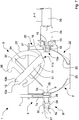
figure 2 is a cross section of the apparatus infigure 1 ; -
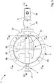
figure 3 is a plan view of the apparatus infigure 1 separated by the dosing machine and in an assembled configuration; -
figure 4 is a section along line IV-IV infigure 3 ; -
figure 5 is a section along line V-V infigure 3 ; -
figure 6 is a section along line VI-VI infigure 3 ; -
figure 7 is a section like the one infigure 4 in which the apparatus infigure 1 is in a dismantling configuration with a mixing element decoupled from a mixing tank; -
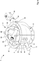
figure 8 is a perspective view of the apparatus infigure 7 . - With reference to
figures 1 to 8 , amixing apparatus 1 according to the invention is illustrated that is associable with adosing machine 50 for mixing plastic products, in particular plastic resins, made of granules and/or flakes or the like and making a homogeneous mixture of the aforesaid plastic products with which to feed, for example, an extruding device of a plastic moulding plant. - The
mixing apparatus 1 comprises a containingelement 2, a so-called mixing tank, arranged for receiving and containing the plastic products that form a mixture to be mixed homogeneously and amixing element 3 housed in the containingelement 2 and rotatable around a rotation axis X so as to move and mix the plastic products. - The
apparatus 1 comprises first coupling means 4 and second coupling means 5 fixed opposite each other, in particular facing and aligned, to aside wall 20 of the containingelement 2 and arranged for receiving and coupling reversibly respectively with afirst end 11 and at asecond end 12 of themixing element 3 to enable the latter to be assembled or dismantled from the containingelement 2. - The
mixing element 3, disclosed better further on in the description, comprises a supportingshaft 31 of elongated shape to which one ormore mixing blades 32 are fixed. Thefirst end 11 and thesecond end 12 of themixing element 3 comprise the respective ends of the supportingshaft 31. - The first coupling means 4 includes a
quick connection element 13 that is rotatable byactuating means 25 and is arranged for coupling with thefirst end 11 of themixing element 3 in an assembling configuration A so as to rotate the latter around the rotation axis X and at the same time prevent movements of thefirst end 11 that are transverse to the aforesaid rotation axis X. - The
connection element 13 in fact comprises afront wall 13a provided withengaging means 15 arranged for abutting on and engaging further engagingmeans 16 made on a respectivefront wall 11a of thefirst end 11. Theengaging means 15 and the further engagingmeans 16 enables rotation torque to be transferred from the actuating means 25 to themixing element 3. - In the illustrated embodiment, the
engaging means 15 comprises three radial grooves that are angularly spaced apart by 120° with respect to a longitudinal axis and are made on thefront wall 13a of circular shape of thequick connection element 13. The further engagingmeans 16 comprises corresponding radial ridges angularly spaced by 120°, made on the respectivecircular front wall 11a of thefirst end 11 and having a shape that is complementary to that of the radial grooves. It should be noted that when the ridges of the further engagingmeans 16 are engaged in the respective grooves of theengaging means 15, thefirst end 11 of themixing element 3 is connected to theconnection element 13 in such a manner that the movements that are transverse, in particular orthogonal, to the rotation axis X, are prevented. - The three grooves and the three ridges that are angularly spaced by 120° besides being dimensioned so as to transfer effectively the rotation torque from the actuating means 25 to the
mixing element 3, enable easy coupling, as explained better further on in the description, of themixing element 3 to the first coupling means 11 in the assembling step. The actuating means 25 comprises, for example, an electric and/or pneumatic motor provided with rotating and/or oscillating and/or pulsating motion connected to theconnection element 13 by means of motionspeed reducing means 24, fixed outside the containingelement 2. - In one embodiment of the apparatus that is not illustrated the
actuating means 25 is fixed directly to theconnection element 13. - The
connection element 13 connected to an output shaft of themotion reducing means 24 is rotatably inserted and supported in a first throughseat 8, fixed to theside wall 20 of the containingmeans 2. An external side wall of theconnection element 13 engaged in thefirst seat 8 has sealing means 18 that prevents the plastic products made of granules and/or flakes and/or powders escaping from the containingelement 2. - The second coupling means 5 comprises bush means 6 fixed slidingly to the
side wall 20 of the containingelement 2 and movable linearly between a locking position L and a release position R. In the locking position L the bush means 6 rotatably engages thesecond end 12 of themixing element 3 so as to prevent the movements of said mixingelement 3 along, and transversely to, said rotation axis X. In the release position R the bush means 6 is disengaged and spaced apart from thesecond end 12 to enable themixing element 3 to be dismantled or assembled on the containingelement 2. - The bush means 6 comprises a cylindrical bush that is slidable in a second through
seat 9 made on theside wall 20 along the rotation axis X. Thebush 6 is aligned on and faces theconnection element 13. - The
bush 6 has afirst end portion 6a provided with ahousing 26 suitable for receiving and rotatably supporting thesecond end 12 of themixing element 3. Asecond end portion 6b of thebush 6 is provided with a grippingpivot 27 for driving thebush 26 manually between the locking position L and release position R. The position of thegripping pivot 27 with respect to thebush 6 can be adjusted by an operator to compensate for possible assembly clearance of the mixingelement 3. - Locking means 7 is provided for locking the bush means 6 in the locking position L.
- As illustrated in particular in
figures 2 and8 , the locking means comprises alocking pivot 7 slidably fixed to theside wall 20 by a supportingelement 44 and movable transversely to the rotation axis X so as to engage or disengage thebush 6 selectively when thebush 6 is in the locking position L. The lockingpivot 7 is mounted slidably in athird seat 10 made in the supportingelement 44 so that an operatingend 7a thereof can be inserted and engage, through first throughholes 28 and second throughholes 29 made respectively in thesecond seat 9 and in thebush 6, in an arrestinghole 30 made in thegripping pivot 27. When inserted and engaged in the arrestinghole 30 of thegripping pivot 27, the lockingpivot 7 prevents movements and rotations of thebush 6 that thus remains locked in the locking position L. The lockingpivot 27 prevents in this manner the mixingelement 3 being able to disengage accidentally from thebush 6 by a shift of the latter. - The locking
pivot 7 is further provided with atransverse pivot 45 that extends transversely, in particular orthogonally to a longitudinal axis of said lockingpivot 7 so as to enable the movement thereof by a user. By rotating the lockingpivot 7 around the longitudinal axis thereof it is further possible to insert thetransverse pivot 45 into arecess 46 of the supportingelement 44, thus arresting the axial movement of the locking pivot in a raised position disengaged from thebush 6. - The
second end 12 of the supportingshaft 3 has anend pivot 12a arranged for being inserted with reduced clearance into thehousing 26, in particular coupling with a bearing, and a machinedperipheral portion 12b that in cooperation with thehousing 26 ensures a seal of the coupling that is such as to prevent plastic material made of granules escaping through thebush 6. - The
side wall 20 of the containingelement 2 comprises abottom portion 21 having a substantially hemispherical shape and comprising anoutflow opening 23 for the exit of the plastic products after mixing. Closing means that is known and not illustrated is provided for opening or closing theoutflow opening 23. - The mixing
element 3 in the illustrated embodiment comprises the supportingshaft 31 having an elongated cylindrical shape and a plurality of mixingblades 32, in particular four, fixed to the supportingshaft 31 angularly spaced apart from one another, for example by 90° and extend almost radially from said supportingshaft 31. Eachmixing blade 32 has a flat shape and has aperipheral edge 33 having a semicircular arched profile and dimensions that are such as to engage theside wall 20 with reduced clearance, in particular thebottom portion 21 of thewall 20 during rotation of the mixingelement 3, in an operating step of the mixing apparatus. Eachmixing blade 32 further has a shaped andarched appendage 36 facing thesecond end 12 of the supportingshaft 31. - Each
mixing blade 32 further comprises a throughopening 34 having a circular sector shape. - The mixing
element 3 is further provided with acircular ring 35 that is coaxial with the supportingshaft 31 that connects themixing blades 32 together. Thering 35 has dimensions and a shape that are such as to engage theside wall 20, in particular thebottom portion 21 of the latter, with reduced clearance during rotation of the mixingelement 3. - Owing to the shape of the
blades 32 of the mixingelement 3 and to the conformation of the containingelement 2, which comprises ahemispherical bottom portion 21, it is possible to shake and mix in an optimum manner the plastic products so as to obtain homogeneous and uniform mixtures of materials even in cases in which the aforesaid materials have a different chemical composition and/or geometry and/or shape and/or density. The mixingapparatus 1 of the invention enables phenomena of separation by gravity and phenomena of segregation by shape of the different materials to be avoided. Numerous tests have shown that the shape and geometry of theblades 32 and of the containingelement 2 prevent the formation within the latter of zones where materials accumulate or collect and they generate an effective undulating movement of the materials that are thus uniformly agitated and mixed. Another aspect observed is the reduction of crushing and generation of dust, in the case of materials consisting of plastic resins made of granules and/or flakes having different hardnesses. Such an undulating movement, with the same final mixing effect, enables the rotation speed of the mixingelement 3 and mixing times to be reduced compared with known apparatuses, this causing less energy consumption and higher productivity. - It has been further observed that the mixing apparatus of the invention enables the phenomena of overheating by frictions of the materials during the mixing step to be avoided or greatly reduced, in particular in the case of mixtures of materials consisting of low-melting plastic resins, i.e. with a softening point close to ambient temperature.
- The
side wall 20 of the containingelement 2 comprises anupper portion 22, having a substantially cylindrical shape and integral with thebottom portion 21. Thisupper portion 22 is fixable to a feedingmanifold 51 of thedosing machine 50 arranged for conveying the plastics dispensed by dosing means of saiddosing machine 50, of known type and not illustrated in the figures, inside the containingelement 2. In particular, theside wall 20 is provided with anupper flange 37 that can be fixed to the feedingmanifold 51. The latter, at the joining zone with theflange 37 of the containingelement 2, has a cross section (with a plane parallel to the rotation axis X and substantially horizontal) having a shape (for example circular) and dimensions almost coinciding with the cross section of theupper portion 22 of theside wall 20 so that aninner wall 51a of theaforesaid feeding manifold 51 is substantially aligned on theaforesaid side wall 20. There being no gaps or fissures in the joining zone, all the plastic material is conveyed inside the containingelement 2 without escapes or dispersion. - The feeding
manifold 51 further has ahatch 52 that enables an operator to access the containingelement 2 and to dismantle or assemble themixing element 3 as explained below in the description. - The
hatch 52 in the closed position prevents movement of the lockingpivot 27 that remains engaged and locks in the locking position L thebush 6 of the second coupling means 12. With thehatch 52 in the closed position it is thus not possible to move thebushing 6 and disengage themixing element 3 from the coupling means 11, 12. - The procedure of assembling the mixing
element 3 provides for positioning thebush 6 in the release position R to enable an operator to insert manually the mixingelement 3 inside the containingelement 2 and engage thefirst end 11 of the supportingshaft 31 on theconnection element 13 of the first coupling means 4. - Owing to the engaging
means 15 and to the further engagingmeans 16 comprising respectively grooves and ridges, spaced angularly by 120° and made on thefront walls first end 11 and of theconnection element 13 it is possible to make easy and rapid coupling. - With the
first end 11 of the supportingshaft 3 maintained engaged on the first coupling means 4 the operator arranges thesecond end 12 at the second coupling means 5 and moves thebush 6 so that it engages with thefirst end 11. In particular, moving thebush 6 from the release position R to the locking position L, theend pivot 12a and the processedperipheral portion 12b of thefirst end 12 enter thehousing 26 of thebush 6. - With the mixing
element 3 correctly engaged in the first coupling means 4 and in the second coupling means 5 in the assembling configuration A, the operator arrests thebush 6 in the locking position L by the lockingpivot 7. In this manner, the mixingelement 3 is assured in the assembling configuration A and themixing apparatus 1 is ready for operation. - The dismantling procedure involves the same operating sequences disclosed above to be followed in reverse order.
- The mixing
element 3 can thus be assembled or dismantled by the mixingapparatus 1 of the invention, for example replaced for ordinary or extraordinary maintenance, in a rapid, easy and simple manner by the operator, without requiring the use of tools. - It is moreover opportune to point out that once the mixing
element 3 has been dismantled and removed the containingelement 2 can be easily and rapidly cleaned by the operator because it already has aside wall 20 of cylindrical and spherical shape that is completely free. - The mixing
apparatus 1 of the invention thus enables ordinary or extraordinary cleaning and/or maintenance operations to be performed without the need to dismantle the containingelement 2 from thedosing machine 50, but simply by extracting the mixingelement 3, i.e. enable the aforesaid operations to be simplified and above all enables the downtime of the apparatus and of the plant on which it is installed to be reduced. - It should be noted that, as the containing
element 2 does not need to be dismantled, it can be fixed to the feedingmanifold 51 of thedosing machine 50 so that in the junction zone between theflange 37 of the containingelement 2 and theinternal wall 51a of theaforesaid feeding manifold 51 there are no gaps and/or fissures in which the plastic material can accumulate descending from the dosing means and the plastic material can be conveyed entirely inside the containingelement 2.
Claims (10)
- Mixing apparatus, in particular associable with a dosing machine (50), for mixing plastic products made of granules and/or flakes, comprising a containing element (2) arranged for receiving and containing said plastic products, a mixing element (3) provided with a first end (11) and with a second end (12), housed in said containing element (2) and rotatable around a rotation axis (X) so as to move and mix said plastic products, and first coupling means (4) and second coupling means (5) fixed opposite each other to a side wall (20) of said containing element (2) and arranged for receiving and coupling reversibly respectively with said first end (11) and with said second end (12) of said mixing element (3) in such a manner as to enable the latter to be assembled or dismantled, characterised in that said side wall (20) comprises a bottom portion (21) having a substantially hemispherical shape, in particular said bottom portion (21) comprising an outflow opening (23) for exiting said plastic products after mixing, and said mixing element (3) comprises a supporting shaft (31) to which a plurality of mixing blades (32) are fixed which are angularly spaced apart from one another, which mixing blades (32) extend almost radially from said supporting shaft (31), wherein said mixing blades (32) have a flat shape and comprise a peripheral edge (33) having a curved shape and dimensions that are such as to engage said bottom portion (21) with reduced clearance during rotation of said mixing element (3), wherein each of said mixing blades (32) comprises a through opening (34) and a shaped and arched appendage (36) facing said second end (12) of said supporting shaft (31), wherein said mixing element (3) further comprises a ring (35) that is substantially coaxial to said supporting shaft (31) and connects said mixing blades (32), said ring (35) having a circular shape and dimensions that are such as to engage said bottom portion (21) with reduced clearance during the rotation of said mixing element (3).
- Apparatus according to claim 1, wherein each of said through opening (34) has a circular sector shape.
- Apparatus according to claim 1, or 2, wherein said mixing blades (32) are angularly spaced apart from one another by 90°.
- Apparatus according to claim 1, wherein said first coupling means (4) comprises a connection element (13) rotated by actuating means (25) and arranged for coupling with said first end (11) of said mixing element (3) in an assembling configuration (A) in such a manner as to rotate the latter around said rotation axis (X) and prevent movements of said first end (11) that are transverse to said rotation axis (X).
- Apparatus according to claim 4, wherein said connection element (13) comprises a respective front wall (13a) provided with engaging means (15) arranged for engaging further engaging means (16) made on a respective front wall (11a) of said first end (11).
- Apparatus according to any preceding claim, wherein said second coupling means (5) comprises bush means (6) fixed slidably to said side wall (20) of said containing element (2) and movable between a locking position (L), wherein said bush means (6) rotatably engages said second end (12) and locks movements of said mixing element (3) along, and traverse to, said rotation axis (X), and a release position (R), wherein said bush means (6) is disengaged and spaced from said second end (12) to enable said mixing element (3) to be dismantled and removed from said containing element (2) or to enable said mixing element (3) to be assembled to said containing element (2).
- Apparatus according to claim 6, comprising locking means (7) arranged for locking said bush means (6) in said locking position (L).
- Apparatus according to claim 7, wherein said locking means (7) comprises a locking pin that is slidably fixed to said side wall (20) and is transversely movable to said rotation axis (X) in such a manner as to selectively engage or disengage said bush means (6) in the locking position (L).
- Apparatus according to any preceding claim, wherein said side wall (20) of the containing element (2) comprises an upper portion (22) that is fixable to or forms a single body with a feeding manifold (51) of said dosing machine (50), said feeding manifold (51) being arranged for conveying said plastic products dispensed by dosing means of said dosing machine (50) inside said containing element (2).
- Dosing machine for dispensing defined quantities of plastic products, in particular plastic resins in the shapes of granules and/or flakes, comprising a mixing apparatus (1) according to any preceding claim.
Priority Applications (1)
| Application Number | Priority Date | Filing Date | Title |
|---|---|---|---|
| PL14173308T PL2818290T3 (en) | 2013-06-24 | 2014-06-20 | Apparatus for mixing resins |
Applications Claiming Priority (1)
| Application Number | Priority Date | Filing Date | Title |
|---|---|---|---|
| IT000181A ITMO20130181A1 (en) | 2013-06-24 | 2013-06-24 | MIXING SYSTEM FOR RESINS |
Publications (2)
| Publication Number | Publication Date |
|---|---|
| EP2818290A1 EP2818290A1 (en) | 2014-12-31 |
| EP2818290B1 true EP2818290B1 (en) | 2016-12-14 |
Family
ID=49035769
Family Applications (1)
| Application Number | Title | Priority Date | Filing Date |
|---|---|---|---|
| EP14173308.9A Active EP2818290B1 (en) | 2013-06-24 | 2014-06-20 | Apparatus for mixing resins |
Country Status (3)
| Country | Link |
|---|---|
| EP (1) | EP2818290B1 (en) |
| IT (1) | ITMO20130181A1 (en) |
| PL (1) | PL2818290T3 (en) |
Family Cites Families (7)
| Publication number | Priority date | Publication date | Assignee | Title |
|---|---|---|---|---|
| US209195A (en) * | 1878-10-22 | Improvement in churns | ||
| US742168A (en) * | 1903-06-13 | 1903-10-27 | Conrad Constine | Coffee-roaster. |
| US1699916A (en) * | 1926-03-10 | 1929-01-22 | Husqvarna Vapenfabriks Ab | Dough-kneading machine |
| DE3346823A1 (en) * | 1983-12-23 | 1985-07-11 | Innkieswerk-GmbH, 8201 Neubeuern | DRY MORTAR MIXING PLANT |
| JPH0712268B2 (en) * | 1988-07-14 | 1995-02-15 | 三洋電機株式会社 | Mixing device in noodle making machine |
| DE9206293U1 (en) * | 1992-05-11 | 1992-08-20 | Thermozell Entwicklungs- und Vertriebs GmbH, Glanegg | Lightweight concrete dosing device |
| US8870443B2 (en) * | 2008-04-17 | 2014-10-28 | Sartorius Stedim Biotech Gmbh | Flexible pouch with a mixing apparatus |
-
2013
- 2013-06-24 IT IT000181A patent/ITMO20130181A1/en unknown
-
2014
- 2014-06-20 EP EP14173308.9A patent/EP2818290B1/en active Active
- 2014-06-20 PL PL14173308T patent/PL2818290T3/en unknown
Non-Patent Citations (1)
| Title |
|---|
| None * |
Also Published As
| Publication number | Publication date |
|---|---|
| ITMO20130181A1 (en) | 2014-12-25 |
| PL2818290T3 (en) | 2017-08-31 |
| EP2818290A1 (en) | 2014-12-31 |
Similar Documents
| Publication | Publication Date | Title |
|---|---|---|
| US8721167B2 (en) | Kneading and granulating machine | |
| JP6986550B2 (en) | Equipment and Methods for Producing Colored and Uncolored Plastic Melts | |
| US3902850A (en) | Solvent-free, self-cleaning mixing head nozzles for reactive polymer mixes | |
| JP7358345B2 (en) | Double screw shaft for kneading machine | |
| CN102671562B (en) | Mixing silo | |
| US9643352B2 (en) | Batch mixer with plunger | |
| CN112848063A (en) | Extrusion equipment for injection molding compound process | |
| AU2016320818B2 (en) | Apparatus and method for injecting a fluid formulation into a melted polymeric material | |
| US5863117A (en) | Method for continuously mixing polymer materials and machine for implementing the method | |
| EP2818290A1 (en) | Apparatus for mixing resins | |
| US12263456B2 (en) | Continuous blender | |
| EP1792643B1 (en) | High volume reactor and/or thin film evaporator employing a premixing device | |
| CN108788005A (en) | A kind of sand mixer and its feed component | |
| CN213726112U (en) | Masterbatch raw materials agitator tank for ratio | |
| CN214605570U (en) | Extrusion equipment for injection molding compound process | |
| CN116749479B (en) | Mixed melting granulator | |
| CN209794259U (en) | Waste plastic particle stirring and batching device | |
| KR101679613B1 (en) | Molding material supplying apparatus | |
| CN213860102U (en) | Mixed mixer of plastic granules production | |
| CN207126493U (en) | Comminutor | |
| WO2010061416A1 (en) | Machine for the continuous mixing of agglomerate composite stone | |
| CN204147801U (en) | A kind of material mixing equipment | |
| Kong et al. | the lubricated die one can extrude materials, eg UHMWPE, by the process which more resembles metal | |
| JPH0330822A (en) | Mixing and kneading apparatus |
Legal Events
| Date | Code | Title | Description |
|---|---|---|---|
| PUAI | Public reference made under article 153(3) epc to a published international application that has entered the european phase |
Free format text: ORIGINAL CODE: 0009012 |
|
| 17P | Request for examination filed |
Effective date: 20140620 |
|
| AK | Designated contracting states |
Kind code of ref document: A1 Designated state(s): AL AT BE BG CH CY CZ DE DK EE ES FI FR GB GR HR HU IE IS IT LI LT LU LV MC MK MT NL NO PL PT RO RS SE SI SK SM TR |
|
| AX | Request for extension of the european patent |
Extension state: BA ME |
|
| R17P | Request for examination filed (corrected) |
Effective date: 20150630 |
|
| RBV | Designated contracting states (corrected) |
Designated state(s): AL AT BE BG CH CY CZ DE DK EE ES FI FR GB GR HR HU IE IS IT LI LT LU LV MC MK MT NL NO PL PT RO RS SE SI SK SM TR |
|
| 17Q | First examination report despatched |
Effective date: 20151116 |
|
| GRAP | Despatch of communication of intention to grant a patent |
Free format text: ORIGINAL CODE: EPIDOSNIGR1 |
|
| RIC1 | Information provided on ipc code assigned before grant |
Ipc: B29B 7/44 20060101AFI20160621BHEP Ipc: F16D 1/10 20060101ALI20160621BHEP Ipc: B01F 7/00 20060101ALI20160621BHEP Ipc: B01F 3/18 20060101ALI20160621BHEP |
|
| INTG | Intention to grant announced |
Effective date: 20160706 |
|
| GRAS | Grant fee paid |
Free format text: ORIGINAL CODE: EPIDOSNIGR3 |
|
| GRAA | (expected) grant |
Free format text: ORIGINAL CODE: 0009210 |
|
| AK | Designated contracting states |
Kind code of ref document: B1 Designated state(s): AL AT BE BG CH CY CZ DE DK EE ES FI FR GB GR HR HU IE IS IT LI LT LU LV MC MK MT NL NO PL PT RO RS SE SI SK SM TR |
|
| REG | Reference to a national code |
Ref country code: GB Ref legal event code: FG4D |
|
| REG | Reference to a national code |
Ref country code: CH Ref legal event code: EP |
|
| REG | Reference to a national code |
Ref country code: IE Ref legal event code: FG4D |
|
| REG | Reference to a national code |
Ref country code: AT Ref legal event code: REF Ref document number: 853168 Country of ref document: AT Kind code of ref document: T Effective date: 20170115 |
|
| REG | Reference to a national code |
Ref country code: DE Ref legal event code: R096 Ref document number: 602014005427 Country of ref document: DE |
|
| PG25 | Lapsed in a contracting state [announced via postgrant information from national office to epo] |
Ref country code: LV Free format text: LAPSE BECAUSE OF FAILURE TO SUBMIT A TRANSLATION OF THE DESCRIPTION OR TO PAY THE FEE WITHIN THE PRESCRIBED TIME-LIMIT Effective date: 20161214 |
|
| REG | Reference to a national code |
Ref country code: CH Ref legal event code: NV Representative=s name: FIAMMENGHI-FIAMMENGHI, CH |
|
| REG | Reference to a national code |
Ref country code: LT Ref legal event code: MG4D |
|
| REG | Reference to a national code |
Ref country code: NL Ref legal event code: MP Effective date: 20161214 |
|
| PG25 | Lapsed in a contracting state [announced via postgrant information from national office to epo] |
Ref country code: NO Free format text: LAPSE BECAUSE OF FAILURE TO SUBMIT A TRANSLATION OF THE DESCRIPTION OR TO PAY THE FEE WITHIN THE PRESCRIBED TIME-LIMIT Effective date: 20170314 Ref country code: SE Free format text: LAPSE BECAUSE OF FAILURE TO SUBMIT A TRANSLATION OF THE DESCRIPTION OR TO PAY THE FEE WITHIN THE PRESCRIBED TIME-LIMIT Effective date: 20161214 Ref country code: LT Free format text: LAPSE BECAUSE OF FAILURE TO SUBMIT A TRANSLATION OF THE DESCRIPTION OR TO PAY THE FEE WITHIN THE PRESCRIBED TIME-LIMIT Effective date: 20161214 Ref country code: GR Free format text: LAPSE BECAUSE OF FAILURE TO SUBMIT A TRANSLATION OF THE DESCRIPTION OR TO PAY THE FEE WITHIN THE PRESCRIBED TIME-LIMIT Effective date: 20170315 |
|
| REG | Reference to a national code |
Ref country code: FR Ref legal event code: PLFP Year of fee payment: 4 |
|
| PG25 | Lapsed in a contracting state [announced via postgrant information from national office to epo] |
Ref country code: FI Free format text: LAPSE BECAUSE OF FAILURE TO SUBMIT A TRANSLATION OF THE DESCRIPTION OR TO PAY THE FEE WITHIN THE PRESCRIBED TIME-LIMIT Effective date: 20161214 Ref country code: RS Free format text: LAPSE BECAUSE OF FAILURE TO SUBMIT A TRANSLATION OF THE DESCRIPTION OR TO PAY THE FEE WITHIN THE PRESCRIBED TIME-LIMIT Effective date: 20161214 Ref country code: HR Free format text: LAPSE BECAUSE OF FAILURE TO SUBMIT A TRANSLATION OF THE DESCRIPTION OR TO PAY THE FEE WITHIN THE PRESCRIBED TIME-LIMIT Effective date: 20161214 |
|
| PG25 | Lapsed in a contracting state [announced via postgrant information from national office to epo] |
Ref country code: NL Free format text: LAPSE BECAUSE OF FAILURE TO SUBMIT A TRANSLATION OF THE DESCRIPTION OR TO PAY THE FEE WITHIN THE PRESCRIBED TIME-LIMIT Effective date: 20161214 |
|
| PG25 | Lapsed in a contracting state [announced via postgrant information from national office to epo] |
Ref country code: CZ Free format text: LAPSE BECAUSE OF FAILURE TO SUBMIT A TRANSLATION OF THE DESCRIPTION OR TO PAY THE FEE WITHIN THE PRESCRIBED TIME-LIMIT Effective date: 20161214 Ref country code: SK Free format text: LAPSE BECAUSE OF FAILURE TO SUBMIT A TRANSLATION OF THE DESCRIPTION OR TO PAY THE FEE WITHIN THE PRESCRIBED TIME-LIMIT Effective date: 20161214 Ref country code: IS Free format text: LAPSE BECAUSE OF FAILURE TO SUBMIT A TRANSLATION OF THE DESCRIPTION OR TO PAY THE FEE WITHIN THE PRESCRIBED TIME-LIMIT Effective date: 20170414 Ref country code: RO Free format text: LAPSE BECAUSE OF FAILURE TO SUBMIT A TRANSLATION OF THE DESCRIPTION OR TO PAY THE FEE WITHIN THE PRESCRIBED TIME-LIMIT Effective date: 20161214 Ref country code: EE Free format text: LAPSE BECAUSE OF FAILURE TO SUBMIT A TRANSLATION OF THE DESCRIPTION OR TO PAY THE FEE WITHIN THE PRESCRIBED TIME-LIMIT Effective date: 20161214 |
|
| PG25 | Lapsed in a contracting state [announced via postgrant information from national office to epo] |
Ref country code: ES Free format text: LAPSE BECAUSE OF FAILURE TO SUBMIT A TRANSLATION OF THE DESCRIPTION OR TO PAY THE FEE WITHIN THE PRESCRIBED TIME-LIMIT Effective date: 20161214 Ref country code: SM Free format text: LAPSE BECAUSE OF FAILURE TO SUBMIT A TRANSLATION OF THE DESCRIPTION OR TO PAY THE FEE WITHIN THE PRESCRIBED TIME-LIMIT Effective date: 20161214 Ref country code: BE Free format text: LAPSE BECAUSE OF FAILURE TO SUBMIT A TRANSLATION OF THE DESCRIPTION OR TO PAY THE FEE WITHIN THE PRESCRIBED TIME-LIMIT Effective date: 20161214 Ref country code: BG Free format text: LAPSE BECAUSE OF FAILURE TO SUBMIT A TRANSLATION OF THE DESCRIPTION OR TO PAY THE FEE WITHIN THE PRESCRIBED TIME-LIMIT Effective date: 20170314 Ref country code: IT Free format text: LAPSE BECAUSE OF FAILURE TO SUBMIT A TRANSLATION OF THE DESCRIPTION OR TO PAY THE FEE WITHIN THE PRESCRIBED TIME-LIMIT Effective date: 20161214 Ref country code: PT Free format text: LAPSE BECAUSE OF FAILURE TO SUBMIT A TRANSLATION OF THE DESCRIPTION OR TO PAY THE FEE WITHIN THE PRESCRIBED TIME-LIMIT Effective date: 20170414 |
|
| REG | Reference to a national code |
Ref country code: DE Ref legal event code: R097 Ref document number: 602014005427 Country of ref document: DE |
|
| PLBE | No opposition filed within time limit |
Free format text: ORIGINAL CODE: 0009261 |
|
| STAA | Information on the status of an ep patent application or granted ep patent |
Free format text: STATUS: NO OPPOSITION FILED WITHIN TIME LIMIT |
|
| 26N | No opposition filed |
Effective date: 20170915 |
|
| PG25 | Lapsed in a contracting state [announced via postgrant information from national office to epo] |
Ref country code: DK Free format text: LAPSE BECAUSE OF FAILURE TO SUBMIT A TRANSLATION OF THE DESCRIPTION OR TO PAY THE FEE WITHIN THE PRESCRIBED TIME-LIMIT Effective date: 20161214 |
|
| PG25 | Lapsed in a contracting state [announced via postgrant information from national office to epo] |
Ref country code: MC Free format text: LAPSE BECAUSE OF FAILURE TO SUBMIT A TRANSLATION OF THE DESCRIPTION OR TO PAY THE FEE WITHIN THE PRESCRIBED TIME-LIMIT Effective date: 20161214 |
|
| PG25 | Lapsed in a contracting state [announced via postgrant information from national office to epo] |
Ref country code: SI Free format text: LAPSE BECAUSE OF FAILURE TO SUBMIT A TRANSLATION OF THE DESCRIPTION OR TO PAY THE FEE WITHIN THE PRESCRIBED TIME-LIMIT Effective date: 20161214 |
|
| REG | Reference to a national code |
Ref country code: IE Ref legal event code: MM4A |
|
| PG25 | Lapsed in a contracting state [announced via postgrant information from national office to epo] |
Ref country code: IE Free format text: LAPSE BECAUSE OF NON-PAYMENT OF DUE FEES Effective date: 20170620 Ref country code: LU Free format text: LAPSE BECAUSE OF NON-PAYMENT OF DUE FEES Effective date: 20170620 |
|
| REG | Reference to a national code |
Ref country code: FR Ref legal event code: PLFP Year of fee payment: 5 |
|
| PG25 | Lapsed in a contracting state [announced via postgrant information from national office to epo] |
Ref country code: MT Free format text: LAPSE BECAUSE OF NON-PAYMENT OF DUE FEES Effective date: 20170620 |
|
| REG | Reference to a national code |
Ref country code: AT Ref legal event code: UEP Ref document number: 853168 Country of ref document: AT Kind code of ref document: T Effective date: 20161214 |
|
| PG25 | Lapsed in a contracting state [announced via postgrant information from national office to epo] |
Ref country code: HU Free format text: LAPSE BECAUSE OF FAILURE TO SUBMIT A TRANSLATION OF THE DESCRIPTION OR TO PAY THE FEE WITHIN THE PRESCRIBED TIME-LIMIT; INVALID AB INITIO Effective date: 20140620 |
|
| PG25 | Lapsed in a contracting state [announced via postgrant information from national office to epo] |
Ref country code: CY Free format text: LAPSE BECAUSE OF FAILURE TO SUBMIT A TRANSLATION OF THE DESCRIPTION OR TO PAY THE FEE WITHIN THE PRESCRIBED TIME-LIMIT Effective date: 20161214 |
|
| PG25 | Lapsed in a contracting state [announced via postgrant information from national office to epo] |
Ref country code: MK Free format text: LAPSE BECAUSE OF FAILURE TO SUBMIT A TRANSLATION OF THE DESCRIPTION OR TO PAY THE FEE WITHIN THE PRESCRIBED TIME-LIMIT Effective date: 20161214 |
|
| PG25 | Lapsed in a contracting state [announced via postgrant information from national office to epo] |
Ref country code: TR Free format text: LAPSE BECAUSE OF FAILURE TO SUBMIT A TRANSLATION OF THE DESCRIPTION OR TO PAY THE FEE WITHIN THE PRESCRIBED TIME-LIMIT Effective date: 20161214 |
|
| PG25 | Lapsed in a contracting state [announced via postgrant information from national office to epo] |
Ref country code: AL Free format text: LAPSE BECAUSE OF FAILURE TO SUBMIT A TRANSLATION OF THE DESCRIPTION OR TO PAY THE FEE WITHIN THE PRESCRIBED TIME-LIMIT Effective date: 20161214 |
|
| P01 | Opt-out of the competence of the unified patent court (upc) registered |
Effective date: 20230420 |
|
| PGFP | Annual fee paid to national office [announced via postgrant information from national office to epo] |
Ref country code: PL Payment date: 20250603 Year of fee payment: 12 Ref country code: DE Payment date: 20250627 Year of fee payment: 12 |
|
| PGFP | Annual fee paid to national office [announced via postgrant information from national office to epo] |
Ref country code: GB Payment date: 20250627 Year of fee payment: 12 |
|
| PGFP | Annual fee paid to national office [announced via postgrant information from national office to epo] |
Ref country code: FR Payment date: 20250625 Year of fee payment: 12 |
|
| PGFP | Annual fee paid to national office [announced via postgrant information from national office to epo] |
Ref country code: AT Payment date: 20250603 Year of fee payment: 12 |
|
| PGFP | Annual fee paid to national office [announced via postgrant information from national office to epo] |
Ref country code: CH Payment date: 20250701 Year of fee payment: 12 |