EP2818280A2 - Pliers apparatus - Google Patents
Pliers apparatus Download PDFInfo
- Publication number
- EP2818280A2 EP2818280A2 EP14250090.9A EP14250090A EP2818280A2 EP 2818280 A2 EP2818280 A2 EP 2818280A2 EP 14250090 A EP14250090 A EP 14250090A EP 2818280 A2 EP2818280 A2 EP 2818280A2
- Authority
- EP
- European Patent Office
- Prior art keywords
- arm
- handle
- pawl
- pivoting link
- end portions
- Prior art date
- Legal status (The legal status is an assumption and is not a legal conclusion. Google has not performed a legal analysis and makes no representation as to the accuracy of the status listed.)
- Withdrawn
Links
Images


Classifications
-
- B—PERFORMING OPERATIONS; TRANSPORTING
- B25—HAND TOOLS; PORTABLE POWER-DRIVEN TOOLS; MANIPULATORS
- B25B—TOOLS OR BENCH DEVICES NOT OTHERWISE PROVIDED FOR, FOR FASTENING, CONNECTING, DISENGAGING OR HOLDING
- B25B7/00—Pliers; Other hand-held gripping tools with jaws on pivoted limbs; Details applicable generally to pivoted-limb hand tools
- B25B7/06—Joints
- B25B7/08—Joints with fixed fulcrum
-
- B—PERFORMING OPERATIONS; TRANSPORTING
- B25—HAND TOOLS; PORTABLE POWER-DRIVEN TOOLS; MANIPULATORS
- B25B—TOOLS OR BENCH DEVICES NOT OTHERWISE PROVIDED FOR, FOR FASTENING, CONNECTING, DISENGAGING OR HOLDING
- B25B13/00—Spanners; Wrenches
- B25B13/46—Spanners; Wrenches of the ratchet type, for providing a free return stroke of the handle
-
- B—PERFORMING OPERATIONS; TRANSPORTING
- B25—HAND TOOLS; PORTABLE POWER-DRIVEN TOOLS; MANIPULATORS
- B25B—TOOLS OR BENCH DEVICES NOT OTHERWISE PROVIDED FOR, FOR FASTENING, CONNECTING, DISENGAGING OR HOLDING
- B25B13/00—Spanners; Wrenches
- B25B13/48—Spanners; Wrenches for special purposes
- B25B13/50—Spanners; Wrenches for special purposes for operating on work of special profile, e.g. pipes
- B25B13/5008—Spanners; Wrenches for special purposes for operating on work of special profile, e.g. pipes for operating on pipes or cylindrical objects
- B25B13/5016—Spanners; Wrenches for special purposes for operating on work of special profile, e.g. pipes for operating on pipes or cylindrical objects by externally gripping the pipe
- B25B13/5025—Spanners; Wrenches for special purposes for operating on work of special profile, e.g. pipes for operating on pipes or cylindrical objects by externally gripping the pipe using a pipe wrench type tool
- B25B13/5041—Spanners; Wrenches for special purposes for operating on work of special profile, e.g. pipes for operating on pipes or cylindrical objects by externally gripping the pipe using a pipe wrench type tool with movable or adjustable jaws
- B25B13/505—Pivotally moving or adjustable
-
- B—PERFORMING OPERATIONS; TRANSPORTING
- B25—HAND TOOLS; PORTABLE POWER-DRIVEN TOOLS; MANIPULATORS
- B25B—TOOLS OR BENCH DEVICES NOT OTHERWISE PROVIDED FOR, FOR FASTENING, CONNECTING, DISENGAGING OR HOLDING
- B25B7/00—Pliers; Other hand-held gripping tools with jaws on pivoted limbs; Details applicable generally to pivoted-limb hand tools
- B25B7/18—Adjusting means for the operating arms
Definitions
- the present invention relates to a pliers apparatus and more specifically, a pliers apparatus that can function as an all-in-one pliers, ratchet and clamping device.
- the invention provides pliers apparatus as specified in claim 1.
- the invention also includes a pliers apparatus as specified in claim 15.
- said first jaw element has a first contact surface. In at least one embodiment, at least a portion of said first contact surface comprises a plurality of teeth.
- said second jaw element has a second contact surface. In at least one embodiment, at least a portion of said second contact surface comprises a plurality of teeth.
- said cam functions as a pawl catch.
- said cam is a roller.
- two sleeves are provided to cover said handles.
- a pliers apparatus comprises a first arm having opposing ends, a first end of said first arm forming a first handle, a second end of said first arm comprising a jaw element, said first arm comprising a channel; a second arm having opposing ends, a first end of said second arm forming a second handle; a second jaw element pivot ally attached to a portion of a second arm, said second arm comprising at least one switch and at least one pawl; and at least one strut having opposing ends, a first end of said strut is pivotally attached to a portion of said second arm, a second end of said strut has a cam, said cam is designed to be fit within said channel of said first arm, said switch is designed to be activated to thereby engage said pawl with said strut so that it functions as a ratcheting device and locks said first and second jaws, said switch is designed to be deactivated to thereby allow said pawl to disengage with said strut so that said apparatus
- a pliers apparatus comprises a first arm having opposing ends, a first end of said first arm forming a first handle, a second end of said first arm comprising a jaw element, said first arm further comprising an arc situated between said handle and said first jaw element, said first arm comprising a channel; a second arm having opposing ends, a first end of said second arm forming a second handle; a second jaw element pivot ally attached to a portion of a second arm, said second arm comprising at least one switch and at least one pawl; and at least one strut having opposing ends, a first end being pivotally attached to a portion of said second arm, a second end of said strut has a cam, said cam is designed to be fit within said channel of said first arm, said switch is designed to be activated to thereby engage said pawl with said strut so that it functions as a ratcheting device and locks said first and second jaws, said switch is designed to be deactivated to thereby allow said
- a pliers apparatus comprises: a first arm having opposing end portions, a first of said end portions forming a first handle and a second of said end portions comprising a first jaw element; a second arm having opposing end portions, a first of said end portions forming a second handle; a second jaw element pivotally attached to said second arm; a switch and a pawl mounted on said second arm; and a pivoting link having a first end pivotally attached to said second arm and having an arcuate flexure portion to allow limited flexing of said pivoting link, wherein said switch is movable to a first position to cause said pawl to engage said pivoting link to lock said first and second jaw elements and permit a ratcheting action and a second position to allow said pawl to disengage the pivoting link to permit free relative movement of said first and second arms.
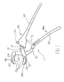
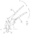
- FIGS. 1 and 2 illustrate an embodiment of a pliers apparatus 1 when in a rest condition.
- the pliers apparatus 1 comprises a first arm having opposing end portions, a first of said end portions forming a first handle 300 and a second of said end portions comprising a first jaw element 201.
- the first arm additionally comprises an arcuate portion 310 disposed between the first jaw element 201 and the first handle 300.
- the pliers apparatus 1 further comprises a second arm having opposing end portions, a first of said end portions forming a second handle 400.
- a second jaw element 202 is pivotally attached to the second arm.
- a switch 501 and a pawl 505 are mounted on the second handle 400.
- the pliers apparatus 1 further comprises a pivoting link 70 having opposing ends, the first of which is pivotally attached to the second arm.
- the switch 501 is movable to a first position to cause the pawl 505 to engage the pivoting link 70 to lock the first and second jaws 201, 202 and permit a ratcheting action of the pawl and a second position to allow the pawl to disengage the pivoting link to permit free relative movement of the first and second arms.
- the first jaw element 201 and the first handle 300 comprise a fixed jaw and a fixed handle and the second jaw element 202 and the second handle 400 comprise a moving jaw and moving handle.
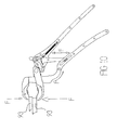
- FIGS. 2 and 3 show a side view of the fixed jaw 201 with a section removed in order to illustrate one method of fixing the fixed jaw to a clamp bar portion 301 of the first arm.
- the clamp bar portion 301 extends from the fixed jaw 201 to the arcuate portion 310.
- the moving jaw 202 can move relative to the fixed jaw 201 by sliding along the clamp bar portion 301.
- MIM Metal Injection Moulding
- the free end of the clamp bar portion 301 is provided with an attachment portion in the form of a split prong 306.
- the split prong 306 is fitted within an aperture 214 provided in the fixed jaw 201.
- the fixed jaw 201 defines abutment surfaces 215 that abut complementary abutment faces 305 of the clamp bar portion 301 to locate the fixed jaw relative to the clamp bar portion.
- the aperture 214 diverges slightly in the direction away from the abutment faces 215, 305 and is configured such that when an appropriately angled barbed wedge 216 is driven into a tapered gap 308 of the split prong 306, the split prong 306 deforms into a wedge shape that grips and fixes the fixed jaw 201 to clamp bar portion 301 so that it is fixedly connected with the fixed handle 300.
- the inner end of the tapered gap 308 has a circular profile 307 that is configured to prevent the occurrence of stress fatigue that might otherwise occur during use.
- the moving jaw 202 is pivotally connected to an end region of the moving handle 400 by a pivot pin 60 ( FIG. 1 ) that extends through axially aligned bores 205 provided in the moving jaw and moving handle.
- the fixed and moving jaws 201, 202 are provided with respective pivoting grip members 207.
- the grip members 207 have a generally elliptical ridged gripping profile 208.
- the grip members 207 are mounted on respective pivot pins 209 disposed in respective cavities 212 provided in the fixed and moving jaws 201, 202.
- the grip members 207 are resiliently biased to the outward position that is shown in FIGS. 1 to 3 by respective compression springs 210.
- the compression springs 210 are mounted within respective bores 213 provided in the grip members 207 and may engage the jaws 201, 202 via optional push rods 211.
- the grip members 207 can rotate around their pivot pins 209 under the influence of the springs 210 so as to protrude from the cavities 212 as shown, but can be easily urged into the corresponding cavities 212 when required.
- the tolerance between the pivot pins 209 and the pivot pin bores in which they are received is chosen so as to ensure that when sufficient force is applied to the gripping profile 208 of a grip member 27, the force is substantially transmitted to the respective jaw 201, 202 by the abutment of a radiussed rear surface 218 of the grip member against a complementary radiussed surface 219 of the respective cavity 212. This ensures that the pivot pins 209 do not have to support the loads applied to the jaws 201, 202 when the pliers apparatus 1 is in use. This prevents the application of undue forces to the pivot pin.
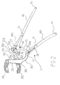
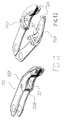
- FIGS. 4 and 5 illustrate a switch mechanism 500.
- the switch mechanism 500 can be set to allow the fixed and moving handles 300, 400 to move freely relative to one another or locked in their last operated position.
- the switch mechanism 500 comprises a switch, or actuator, 501 that can be manually positioned in the required operative position.
- the switch 501 includes a push rod 502 and an actuator spring 503 that acts against the push rod.
- the push rod 502 is urged by the actuator spring 503 against the pawl 505, which functions as a swivelling locking member.
- the push rod 502 engages in an actuation recess 509 defined in the pawl 505.
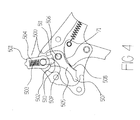
- FIG. 4 illustrates the switch 501 in a locking position in which the push rod 502 is pressed against a locking portion, or side, 510 of the actuation recess 509 to rotate the pawl 505 around its swivel axle 506 and bring the pawl teeth 508 brought into engagement with the teeth of a toothed portion 71 of the pivoting link 70.
- the gripping force applied by the fixed and moving jaws 201, 202 is progressively increased allowing the operator to conveniently apply the correct gripping force for the particular job encountered.
- the switch 501 can be rotated from the locking position shown in FIG. 4 to the unlocking position shown in FIG. 5 .
- the push rod 502 is pressed against an unlocking portion, or side, 511 of the actuation recess 509 to rotate the pawl 505 to a position in which its teeth 508 are completely disengaged from the teeth of the toothed portion 71.
- the teeth of the toothed portion 71 and pawl 505 have a sawtooth profile, the fixed and moving handles 300, 400 need to be squeezed towards one another to finally release the switch mechanism 500. This provides a safety lock against accidental unlocking.
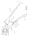
- FIG. 7 illustrates the pliers apparatus 1 in a partially activated condition in which the fixed and moving handles 300, 400 have been closed, and optionally locked, with the gripping profiles 208 of the grip members 207 engaging the periphery of a fastener 90 Depending on the size/profile of the fastener 90, the grip members 207 protrude more of less out of their respective cavities 212 under the influence of the resilient biasing force provided by the compression springs 210 and engage the surface of the fastener 90.
- the grip members 207 When the pliers apparatus 1 is rotated in the drive D (clockwise as viewed in the drawing) direction, the grip members 207 tighten against the fastener 90 as the elliptical ridged gripping profiles 208 reduce the gap between the grip members 207. This improves the grip on the fastener 90.
- FIG. 8 shows the pliers apparatus 1 being actuated in the reverse (anticlockwise as viewed in the drawing) direction in which the grip members 207 are pressed into their cavities 212 by the fastener 90 pushing against the force exerted by the springs 210.
- FIGS. 9 and 10 illustrate the pliers apparatus 1 in use as a clamping device. There are myriad reasons for using the pliers apparatus 1 as a clamping device, including clamping and gripping in order to turn a fastener 90, especially a worn or damaged one, to clamping two pieces of metal 93 together prior to welding them.
- a common failing in prior art devices is that if, for whatever reason, the dimension of the part of the clamped object, or objects, on which the clamping device acts reduces, even slightly, the fixed grip imparted results in a failure to maintain a grip on the object.
- the pliers apparatus 1 deliberately incorporates an extremely strong method of resiliently closing or further resiliently locking the grip applied via the fixed and moving jaws 201, 202.
- the resilience that provides this improved gripping is provided by the arcuate portion 310 provided in the first arm between the fixed handle 300 and clamp bar portion 301. In other examples, the resilience may be incorporated into the pivoting link 70, or moving handle 400.
- the profile, material and thickness of the resilient portion is carefully chosen in order to provide a repeatable resilience with the least chance of stress cracking during repeated use.
- the profile of the resilient portion, such as the arcuate portion 310 is preferably a slow curve or arc in the direction of the closing handle 300, 400 force.
- the arcuate portion 310 arches in a direction generally away from the moving handle 400.
- the arcuate portion 310 may have an arc length in the range from about 40 degrees to about 140 degrees.
- the arc length is the length of the arc between the clamp bar portion 301 and the fixed handle 300.
- the arcuate portion 310 may have a width in the radial direction thereof that is from about 5% to about 80% thinner than the width of the second end portion of the first arm, which in the illustrated embodiment is the fixed handle 300.
- the width is the dimension in the plane of the drawing measured perpendicular to the length of the part.
- the pivoting link 70 is rotatable around the pin 61 on which it is mounted to the moving handle 400 so that when the handles 300, 400 are clenched to close the jaws 201, 202 against a workpiece (such as the fastener 90 or pieces of metal 93), as the handles 300, 400 are pushed harder together against the resistance provided by the workpiece, the moving handle 400 pivots around the pivot pin 60 and the roller 62 fitted on the end of the pivoting link 70 that is opposite the end that comprises the toothed portion 71 rolls down the fixed handle 300 away from the fixed jaw 201.
- a workpiece such as the fastener 90 or pieces of metal 93
- the roller 62 functions as a cam as it rolls on a roller surface 304 defined by the fixed handle 300 guided within the sliding slot 311.
- the teeth of the toothed portion 71 of the pivoting link 70 "ratchet" over the corresponding teeth 508 on the pawl 505 according to the closing pressure applied.
- the teeth of the toothed portion 71 and pawl 505 engage in a locking manner.
- the sawtooth profile prevents slippage of the teeth in a direction that would reduce the applied clamping force.
- the flex induced within the living spring formed by the arcuate portion 310 and in the jaws 201, 202 is maintained by the angle of the pivoting link 70 and the engagement of roller pin 62 within the sliding slot 311.
- the arcuate portion 310, pivoting link 70, portion of the moving handle 400 between the pivoting link the moving jaw 202 and the portion of the moving jaw 202 disposed between the moving handle and clamp bar portion 301 form a rhombus-shaped frame in which the tension can be retained for the purposes of placing the jaws 201, 202 in a resilient gripping tension. If the workpiece, or object being gripped, is subjected to movement or vibration that would defeat the rigid clamping effect of prior art devices, this tension in the pliers apparatus 1 will maintain it's a grip, albeit that the strength of the grip may be reduced.
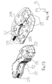
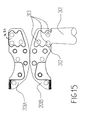
- FIGS. 11 to 15 illustrate in detail an example construction of the fixed and moving jaws 201, 202.
- the jaws 201, 202 are split lengthwise in order that they can be metal moulded, preferably by a High Pressure Metal Moulding method, which is a novel method of 2D or open and shut injection moulding of a metal particle and plasticiser mix at extremely high pressure with, if required, further treatment in a vacuum oven. This method is approximately 30% less expensive than existing metal moulding (MIM) methods.
- MIM metal moulding
- the fixed jaw 201 can be attached to the fixed handle 300 by providing complementary attachment profiles 221, 312 in the jaw parts 201 a, 201b and on the handle. Riveted jaw pins 75 ( FIG. 13 ) may be secured in attachment pin holes 313 to help mechanically secure the two parts of the jaws 201, 202 together.
Landscapes
- Engineering & Computer Science (AREA)
- Mechanical Engineering (AREA)
- Gripping Jigs, Holding Jigs, And Positioning Jigs (AREA)
- Adornments (AREA)
- Hand Tools For Fitting Together And Separating, Or Other Hand Tools (AREA)
- Manufacturing Of Electrical Connectors (AREA)
Abstract
Description
- The present invention relates to a pliers apparatus and more specifically, a pliers apparatus that can function as an all-in-one pliers, ratchet and clamping device.
- The invention provides pliers apparatus as specified in
claim 1. - The invention also includes a pliers apparatus as specified in claim 15.
- In at least one embodiment said first jaw element has a first contact surface. In at least one embodiment, at least a portion of said first contact surface comprises a plurality of teeth.
- In at least one embodiment, said second jaw element has a second contact surface. In at least one embodiment, at least a portion of said second contact surface comprises a plurality of teeth.
- In at least one embodiment, there is at least one shoe designed to assist in having said jaw elements close parallel to one another to provide a tight grip. In at least one embodiment said cam functions as a pawl catch. In at least one embodiment, said cam is a roller. In at least one embodiment, two sleeves are provided to cover said handles.
- In at least one embodiment, a pliers apparatus comprises a first arm having opposing ends, a first end of said first arm forming a first handle, a second end of said first arm comprising a jaw element, said first arm comprising a channel; a second arm having opposing ends, a first end of said second arm forming a second handle; a second jaw element pivot ally attached to a portion of a second arm, said second arm comprising at least one switch and at least one pawl; and at least one strut having opposing ends, a first end of said strut is pivotally attached to a portion of said second arm, a second end of said strut has a cam, said cam is designed to be fit within said channel of said first arm, said switch is designed to be activated to thereby engage said pawl with said strut so that it functions as a ratcheting device and locks said first and second jaws, said switch is designed to be deactivated to thereby allow said pawl to disengage with said strut so that said apparatus functions as pliers.
- In at least one embodiment, a pliers apparatus comprises a first arm having opposing ends, a first end of said first arm forming a first handle, a second end of said first arm comprising a jaw element, said first arm further comprising an arc situated between said handle and said first jaw element, said first arm comprising a channel; a second arm having opposing ends, a first end of said second arm forming a second handle; a second jaw element pivot ally attached to a portion of a second arm, said second arm comprising at least one switch and at least one pawl; and at least one strut having opposing ends, a first end being pivotally attached to a portion of said second arm, a second end of said strut has a cam, said cam is designed to be fit within said channel of said first arm, said switch is designed to be activated to thereby engage said pawl with said strut so that it functions as a ratcheting device and locks said first and second jaws, said switch is designed to be deactivated to thereby allow said pawl to disengage with said strut so that said apparatus functions as pliers, wherein said first and second jaw elements are moved and contact one another by squeezing said first and second handles.
- In at least one embodiment a pliers apparatus comprises: a first arm having opposing end portions, a first of said end portions forming a first handle and a second of said end portions comprising a first jaw element; a second arm having opposing end portions, a first of said end portions forming a second handle; a second jaw element pivotally attached to said second arm; a switch and a pawl mounted on said second arm; and a pivoting link having a first end pivotally attached to said second arm and having an arcuate flexure portion to allow limited flexing of said pivoting link, wherein said switch is movable to a first position to cause said pawl to engage said pivoting link to lock said first and second jaw elements and permit a ratcheting action and a second position to allow said pawl to disengage the pivoting link to permit free relative movement of said first and second arms.
- In order that the invention may be well understood, some embodiments thereof, which are given by way of example only, will now be described with reference to the drawings, in which:
-
FIGURE 1 is a side perspective view of pliers apparatus according to the invention shown in a closed condition; -
FIGURE 2 shows a partially cutaway view corresponding toFIG. 1 ; -
FIGURE 3 is a cutaway view of the fixed jaw of the pliers apparatus; -
FIGURE 4 is a cutaway showing internals of the pliers apparatus; -
FIGURE 5 is a view corresponding toFIG. 4 showing another condition of the pliers apparatus; -
FIGURE 6 is a side view of a pivoting link of the pliers apparatus; -
FIGURE 7 is a side view of the pliers apparatus engaging a bolt; -
FIGURE 8 is a view corresponding toFIG. 7 showing a cutaway of the jaws; -
FIGURE 9 is a side view of the pliers apparatus in use as a clamping device; -
FIGURE 10 is a view corresponding toFIG. 9 with a cutaway view of the moving handle; -
FIGURE 11 is a perspective view of a moving jaw of the pliers apparatus; -
FIGURE 12 is a perspective view of two disassembled elements of the moving jaw ofFIG. 11 ; -
FIGURE 13 is a perspective view of a fixed jaw of the pliers apparatus; -
FIGURE 14 is a perspective view of three disassembled elements of the fixed jaw ofFIG. 13 ; and -
FIGURE 15 is illustrates attachment of the fixed jaw elements ofFIG. 14 to a first arm of the pliers apparatus. - It is to be understood that the disclosed embodiments are merely examples and that the drawings are not necessarily to scale. Some features shown in the drawings may be exaggerated to show details of particular components. Therefore, specific structural and functional details disclosed herein are not to be interpreted as limiting, but merely as a basis for the claims and as a representative basis disclosing the invention to those skilled in the art.
-
FIGS. 1 and2 illustrate an embodiment of apliers apparatus 1 when in a rest condition. Thepliers apparatus 1 comprises a first arm having opposing end portions, a first of said end portions forming afirst handle 300 and a second of said end portions comprising afirst jaw element 201. The first arm additionally comprises anarcuate portion 310 disposed between thefirst jaw element 201 and thefirst handle 300. Thepliers apparatus 1 further comprises a second arm having opposing end portions, a first of said end portions forming asecond handle 400. Asecond jaw element 202 is pivotally attached to the second arm. Aswitch 501 and apawl 505 are mounted on thesecond handle 400. Thepliers apparatus 1 further comprises a pivotinglink 70 having opposing ends, the first of which is pivotally attached to the second arm. Theswitch 501 is movable to a first position to cause thepawl 505 to engage thepivoting link 70 to lock the first andsecond jaws first jaw element 201 and thefirst handle 300 comprise a fixed jaw and a fixed handle and thesecond jaw element 202 and thesecond handle 400 comprise a moving jaw and moving handle. -
FIGS. 2 and3 show a side view of thefixed jaw 201 with a section removed in order to illustrate one method of fixing the fixed jaw to aclamp bar portion 301 of the first arm. Theclamp bar portion 301 extends from thefixed jaw 201 to thearcuate portion 310. The movingjaw 202 can move relative to thefixed jaw 201 by sliding along theclamp bar portion 301. Although many differing types of manufacture of the attachment components could be utilised, the example shown is one in which parts manufactured by Metal Injection Moulding (MIM) are used. The free end of theclamp bar portion 301 is provided with an attachment portion in the form of asplit prong 306. Thesplit prong 306 is fitted within anaperture 214 provided in thefixed jaw 201. On either side of theaperture 214 thefixed jaw 201 definesabutment surfaces 215 that abut complementary abutment faces 305 of theclamp bar portion 301 to locate the fixed jaw relative to the clamp bar portion. Theaperture 214 diverges slightly in the direction away from theabutment faces angled barbed wedge 216 is driven into atapered gap 308 of thesplit prong 306, thesplit prong 306 deforms into a wedge shape that grips and fixes thefixed jaw 201 toclamp bar portion 301 so that it is fixedly connected with thefixed handle 300. The inner end of thetapered gap 308 has acircular profile 307 that is configured to prevent the occurrence of stress fatigue that might otherwise occur during use. - The moving
jaw 202 is pivotally connected to an end region of themoving handle 400 by a pivot pin 60 (FIG. 1 ) that extends through axially alignedbores 205 provided in the moving jaw and moving handle. - The fixed and moving
jaws pivoting grip members 207. In the illustrated embodiment, thegrip members 207 have a generally ellipticalridged gripping profile 208. As best seen inFIG. 3 , thegrip members 207 are mounted onrespective pivot pins 209 disposed inrespective cavities 212 provided in the fixed and movingjaws grip members 207 are resiliently biased to the outward position that is shown inFIGS. 1 to 3 byrespective compression springs 210. Thecompression springs 210 are mounted withinrespective bores 213 provided in thegrip members 207 and may engage thejaws optional push rods 211. Thegrip members 207 can rotate around theirpivot pins 209 under the influence of thesprings 210 so as to protrude from thecavities 212 as shown, but can be easily urged into thecorresponding cavities 212 when required. The tolerance between thepivot pins 209 and the pivot pin bores in which they are received is chosen so as to ensure that when sufficient force is applied to thegripping profile 208 of a grip member 27, the force is substantially transmitted to therespective jaw rear surface 218 of the grip member against a complementaryradiussed surface 219 of therespective cavity 212. This ensures that thepivot pins 209 do not have to support the loads applied to thejaws pliers apparatus 1 is in use. This prevents the application of undue forces to the pivot pin. -
FIGS. 4 and5 illustrate aswitch mechanism 500. Theswitch mechanism 500 can be set to allow the fixed and movinghandles - The
switch mechanism 500 comprises a switch, or actuator, 501 that can be manually positioned in the required operative position. In the illustrated embodiment theswitch 501 includes apush rod 502 and anactuator spring 503 that acts against the push rod. Thepush rod 502 is urged by theactuator spring 503 against thepawl 505, which functions as a swivelling locking member. Thepush rod 502 engages in anactuation recess 509 defined in thepawl 505.FIG. 4 illustrates theswitch 501 in a locking position in which thepush rod 502 is pressed against a locking portion, or side, 510 of theactuation recess 509 to rotate thepawl 505 around itsswivel axle 506 and bring thepawl teeth 508 brought into engagement with the teeth of atoothed portion 71 of the pivotinglink 70. As thehandles jaws - The
switch 501 can be rotated from the locking position shown inFIG. 4 to the unlocking position shown inFIG. 5 . When theswitch 501 is rotated into the unlocking position, thepush rod 502 is pressed against an unlocking portion, or side, 511 of theactuation recess 509 to rotate thepawl 505 to a position in which itsteeth 508 are completely disengaged from the teeth of thetoothed portion 71. As the teeth of thetoothed portion 71 andpawl 505 have a sawtooth profile, the fixed and movinghandles switch mechanism 500. This provides a safety lock against accidental unlocking. -
FIG. 7 illustrates thepliers apparatus 1 in a partially activated condition in which the fixed and movinghandles gripping profiles 208 of thegrip members 207 engaging the periphery of afastener 90 Depending on the size/profile of thefastener 90, thegrip members 207 protrude more of less out of theirrespective cavities 212 under the influence of the resilient biasing force provided by the compression springs 210 and engage the surface of thefastener 90. When thepliers apparatus 1 is rotated in the drive D (clockwise as viewed in the drawing) direction, thegrip members 207 tighten against thefastener 90 as the elliptical ridged grippingprofiles 208 reduce the gap between thegrip members 207. This improves the grip on thefastener 90. -
FIG. 8 shows thepliers apparatus 1 being actuated in the reverse (anticlockwise as viewed in the drawing) direction in which thegrip members 207 are pressed into theircavities 212 by thefastener 90 pushing against the force exerted by thesprings 210.FIGS. 9 and10 illustrate thepliers apparatus 1 in use as a clamping device. There are myriad reasons for using thepliers apparatus 1 as a clamping device, including clamping and gripping in order to turn afastener 90, especially a worn or damaged one, to clamping two pieces ofmetal 93 together prior to welding them. A common failing in prior art devices is that if, for whatever reason, the dimension of the part of the clamped object, or objects, on which the clamping device acts reduces, even slightly, the fixed grip imparted results in a failure to maintain a grip on the object. In order to overcome this failing, thepliers apparatus 1 deliberately incorporates an extremely strong method of resiliently closing or further resiliently locking the grip applied via the fixed and movingjaws arcuate portion 310 provided in the first arm between the fixedhandle 300 and clampbar portion 301. In other examples, the resilience may be incorporated into the pivotinglink 70, or movinghandle 400. The profile, material and thickness of the resilient portion is carefully chosen in order to provide a repeatable resilience with the least chance of stress cracking during repeated use. The profile of the resilient portion, such as thearcuate portion 310 is preferably a slow curve or arc in the direction of theclosing handle - In the illustrated embodiment the
arcuate portion 310 arches in a direction generally away from the movinghandle 400. Thearcuate portion 310 may have an arc length in the range from about 40 degrees to about 140 degrees. In the illustrated embodiment the arc length is the length of the arc between theclamp bar portion 301 and the fixedhandle 300. Thearcuate portion 310 may have a width in the radial direction thereof that is from about 5% to about 80% thinner than the width of the second end portion of the first arm, which in the illustrated embodiment is the fixedhandle 300. The width is the dimension in the plane of the drawing measured perpendicular to the length of the part. - Referring to
FIGS. 4 and5 , in order to provide a means of adjusting the clamping pressure exerted by the fixed and movingjaws link 70 is rotatable around thepin 61 on which it is mounted to the movinghandle 400 so that when thehandles jaws fastener 90 or pieces of metal 93), as thehandles handle 400 pivots around thepivot pin 60 and theroller 62 fitted on the end of the pivotinglink 70 that is opposite the end that comprises thetoothed portion 71 rolls down the fixedhandle 300 away from the fixedjaw 201. Theroller 62 functions as a cam as it rolls on aroller surface 304 defined by the fixedhandle 300 guided within the slidingslot 311. The teeth of thetoothed portion 71 of the pivotinglink 70 "ratchet" over the correspondingteeth 508 on thepawl 505 according to the closing pressure applied. When the user reaches the level of clamping required and releases the applied grip from thehandles toothed portion 71 andpawl 505 engage in a locking manner. The sawtooth profile prevents slippage of the teeth in a direction that would reduce the applied clamping force. The flex induced within the living spring formed by thearcuate portion 310 and in thejaws link 70 and the engagement ofroller pin 62 within the slidingslot 311. As shown inFIG. 1 , thearcuate portion 310, pivotinglink 70, portion of the movinghandle 400 between the pivoting link the movingjaw 202 and the portion of the movingjaw 202 disposed between the moving handle and clampbar portion 301 form a rhombus-shaped frame in which the tension can be retained for the purposes of placing thejaws pliers apparatus 1 will maintain it's a grip, albeit that the strength of the grip may be reduced. -
FIGS. 11 to 15 illustrate in detail an example construction of the fixed and movingjaws jaws jaws cavities 212 and allows the manufacture of more complex shapes than would be the case if a one-piece moulding, pressing or forging process were used. - As shown in
FIG. 15 the fixedjaw 201 can be attached to the fixedhandle 300 by providing complementary attachment profiles 221, 312 in the jaw parts 201 a, 201b and on the handle. Riveted jaw pins 75 (FIG. 13 ) may be secured in attachment pin holes 313 to help mechanically secure the two parts of thejaws - Numerous modifications and variations of the invention are possible in light of the above disclosure. It is, therefore, to be understood that within the scope of the claims, the invention may be practiced otherwise than as specifically disclosed herein.
Claims (15)
- A pliers apparatus comprising:a first arm having opposing end portions, a first of said end portions forming a first handle (300) and a second of said end portions comprising a first jaw element (201);a second arm having opposing end portions, a first of said end portions forming a second handle (400);an arcuate portion (310) provided in one of said arms to permit limited flexing of the handle (300, 400) of the respective arm;a second jaw element (202) pivotally attached to said second arm;a switch (501) and a pawl (505) mounted on said second arm; anda pivoting link (70) having a first end pivotally attached to said second arm,wherein said switch is movable to a first position to cause said pawl to engage said pivoting link to lock said first and second jaw elements and permit a ratcheting action and a second position to allow said pawl to disengage the pivoting link to permit free relative movement of said first and second arms.
- The apparatus of claim 1, wherein a second end of said pivoting link comprises a cam (62) that is slideable in a guide channel (311) provided in said first arm.
- The apparatus of claim 2, wherein said cam comprises a roller (62) mounted on said second end of the pivoting link (70).
- The apparatus of claim 1, 2 or 3, wherein said arcuate portion (310) has an arc length in the range from about 40 degrees to about 140 degrees.
- The apparatus of any one of the preceding claims, wherein said arcuate portion (310) has a width in the radial direction thereof that is from about 5% to about 80% thinner than the width of said second end portion of said first arm.
- The apparatus of any one of the preceding claims wherein said switch (501) comprises a push rod (502) engaging said pawl (505) and at least one spring (503) arranged to push said push rod towards said pawl.
- The apparatus of any one of the preceding claims, wherein said pivoting link (70) has a plurality of teeth (71) arranged to be engaged by said pawl (505) when said switch (501) is in said first position.
- The apparatus of any one of the preceding claims, wherein said first arm comprises a clamp bar portion (301) and said second jaw element (202) is configured for sliding movement along said clamp bar portion.
- The apparatus of claim 8, wherein a free end (306) of said clamp bar portion is received in a tapering aperture (214) provided in said first jaw element (201) and said first jaw element is secured to said clamp bar portion by a barbed wedge member (216) driven into a tapered hole defined in said free end to deform said free end to form a wedge fitting in said tapering aperture.
- The apparatus of any one of the preceding claims, wherein said arcuate portion is provided in said first arm.
- The apparatus of claim 10, wherein said arcuate portion (310) arches in a direction away from said second handle.
- The apparatus of claim 10 or11, wherein said arcuate portion (310) is configured to allow limited flexing of said first handle (300) relative to said first jaw element (201).
- The apparatus of claim 10, 11 or 12, wherein said limited flexing is flexing of said first handle (300) towards said second handle (400).
- The apparatus of any one of the preceding claims, wherein each of said first and second jaw elements (201, 202) is provided with a cavity (212) in which a respective grip member (207) and biasing spring (210) are provided, the grip members each having an elliptical gripping profile (208), the biasing members biasing the respective grip members to protrude from the respective cavities into a space defined between the first and second jaw elements for engaging an object received in said space.
- A pliers apparatus comprising:a first arm having opposing end portions, a first of said end portions fonning a first handle, a second of said end portions comprising a first jaw element and said first arm comprising a channel;a second arm having opposing end portions, a first of said end portions forming a second handle;a second jaw element pivotally attached to said second arm;a switch and a pawl mounted on said second arm; anda pivoting link, a first end of said pivoting link being pivotally attached to said second arm and a second end of said pivoting link being provided with a cam,wherein said cam is disposed within said channel and said switch movable to a first position to cause said pawl to engage said pivoting link to lock said first and second jaw elements and provide a ratcheting action and a second position to allow said pawl to disengage with said pivoting link to permit free relative moment of said first and second arms.
Applications Claiming Priority (1)
| Application Number | Priority Date | Filing Date | Title |
|---|---|---|---|
| GB201311698A GB201311698D0 (en) | 2013-06-28 | 2013-06-28 | Plier apparatus |
Publications (2)
| Publication Number | Publication Date |
|---|---|
| EP2818280A2 true EP2818280A2 (en) | 2014-12-31 |
| EP2818280A3 EP2818280A3 (en) | 2015-07-22 |
Family
ID=48999273
Family Applications (1)
| Application Number | Title | Priority Date | Filing Date |
|---|---|---|---|
| EP14250090.9A Withdrawn EP2818280A3 (en) | 2013-06-28 | 2014-06-30 | Pliers apparatus |
Country Status (3)
| Country | Link |
|---|---|
| EP (1) | EP2818280A3 (en) |
| GB (1) | GB201311698D0 (en) |
| RU (1) | RU2014126495A (en) |
Cited By (7)
| Publication number | Priority date | Publication date | Assignee | Title |
|---|---|---|---|---|
| WO2017153744A2 (en) | 2016-03-07 | 2017-09-14 | Nigel Buchanan | Hand operated gripping tool |
| WO2017153743A2 (en) | 2016-03-07 | 2017-09-14 | Nigel Buchanan | Hand operated gripping tools |
| WO2017153742A2 (en) | 2016-03-07 | 2017-09-14 | Nigel Buchanan | Hand operated gripping tools |
| WO2019086825A1 (en) | 2017-10-30 | 2019-05-09 | Nigel Alexander Buchanan | Interchangeable jaw pliers |
| GB2617198A (en) * | 2022-04-01 | 2023-10-04 | Reliance Worldwide Corporation Uk Ltd | A tool for a plumbing connector |
| WO2023194722A2 (en) | 2022-04-04 | 2023-10-12 | Nigel Buchanan | Pliers |
| WO2023194723A2 (en) | 2022-04-04 | 2023-10-12 | Nigel Buchanan | Pliers |
Family Cites Families (4)
| Publication number | Priority date | Publication date | Assignee | Title |
|---|---|---|---|---|
| US4922770A (en) * | 1988-05-16 | 1990-05-08 | American Pneumatic Technologies, Inc. | Adjustable pliers |
| US5020399A (en) * | 1990-03-12 | 1991-06-04 | Snap-On Tools Corporation | Self-adjusting pliers with curved handles |
| US6014917A (en) * | 1998-07-01 | 2000-01-18 | B!G Ventures, L.L.C. | Self-adjusting and/or self-locking pliers |
| CA2276121C (en) * | 1999-06-21 | 2004-03-30 | Super-Ego Tools, S.A. | Self-adjusting pliers |
-
2013
- 2013-06-28 GB GB201311698A patent/GB201311698D0/en not_active Ceased
-
2014
- 2014-06-30 EP EP14250090.9A patent/EP2818280A3/en not_active Withdrawn
- 2014-06-30 RU RU2014126495A patent/RU2014126495A/en not_active Application Discontinuation
Non-Patent Citations (1)
| Title |
|---|
| None |
Cited By (7)
| Publication number | Priority date | Publication date | Assignee | Title |
|---|---|---|---|---|
| WO2017153744A2 (en) | 2016-03-07 | 2017-09-14 | Nigel Buchanan | Hand operated gripping tool |
| WO2017153743A2 (en) | 2016-03-07 | 2017-09-14 | Nigel Buchanan | Hand operated gripping tools |
| WO2017153742A2 (en) | 2016-03-07 | 2017-09-14 | Nigel Buchanan | Hand operated gripping tools |
| WO2019086825A1 (en) | 2017-10-30 | 2019-05-09 | Nigel Alexander Buchanan | Interchangeable jaw pliers |
| GB2617198A (en) * | 2022-04-01 | 2023-10-04 | Reliance Worldwide Corporation Uk Ltd | A tool for a plumbing connector |
| WO2023194722A2 (en) | 2022-04-04 | 2023-10-12 | Nigel Buchanan | Pliers |
| WO2023194723A2 (en) | 2022-04-04 | 2023-10-12 | Nigel Buchanan | Pliers |
Also Published As
| Publication number | Publication date |
|---|---|
| GB201311698D0 (en) | 2013-08-14 |
| EP2818280A3 (en) | 2015-07-22 |
| RU2014126495A (en) | 2016-01-27 |
Similar Documents
| Publication | Publication Date | Title |
|---|---|---|
| EP2818280A2 (en) | Pliers apparatus | |
| US9242350B2 (en) | Plier apparatus | |
| US9272394B2 (en) | Pliers apparatus | |
| US9010222B2 (en) | Adjustable gripping tool | |
| US8601856B2 (en) | Pliers head with a locator | |
| EP2243598B1 (en) | Ratcheting adjustable wrench | |
| EP2620258B1 (en) | Locking pliers with handle locking mechanism | |
| EP2546028A1 (en) | Locking pliers | |
| EP2149427A1 (en) | Quick adjusting multi-position pliers | |
| US20150000477A1 (en) | Locking Pliers | |
| US20210245332A1 (en) | Hand Operated Gripping Tool | |
| US9950409B2 (en) | Clamping device with removable handles | |
| US11969866B2 (en) | Manual clamp | |
| US9962813B2 (en) | Pliers apparatus | |
| CA2595193A1 (en) | Clamping tool | |
| US20150239102A1 (en) | Locking Pliers | |
| TW201908065A (en) | Pliers | |
| EP3251797B1 (en) | Pliers | |
| CN105983921A (en) | Ratchet clamp | |
| US2576286A (en) | Quick release attachment for vise grip pliers | |
| US11554465B2 (en) | Locking parallel pliers | |
| US20170355066A1 (en) | Ratchet clamp | |
| US20090320650A1 (en) | Adjustable wrench | |
| US10272545B2 (en) | Locking pliers | |
| US994682A (en) | Wrench. |
Legal Events
| Date | Code | Title | Description |
|---|---|---|---|
| PUAI | Public reference made under article 153(3) epc to a published international application that has entered the european phase |
Free format text: ORIGINAL CODE: 0009012 |
|
| 17P | Request for examination filed |
Effective date: 20140630 |
|
| AK | Designated contracting states |
Kind code of ref document: A2 Designated state(s): AL AT BE BG CH CY CZ DE DK EE ES FI FR GB GR HR HU IE IS IT LI LT LU LV MC MK MT NL NO PL PT RO RS SE SI SK SM TR |
|
| AX | Request for extension of the european patent |
Extension state: BA ME |
|
| PUAL | Search report despatched |
Free format text: ORIGINAL CODE: 0009013 |
|
| AK | Designated contracting states |
Kind code of ref document: A3 Designated state(s): AL AT BE BG CH CY CZ DE DK EE ES FI FR GB GR HR HU IE IS IT LI LT LU LV MC MK MT NL NO PL PT RO RS SE SI SK SM TR |
|
| AX | Request for extension of the european patent |
Extension state: BA ME |
|
| RIC1 | Information provided on ipc code assigned before grant |
Ipc: B25B 7/18 20060101ALI20150615BHEP Ipc: B25B 13/50 20060101ALI20150615BHEP Ipc: B25B 13/46 20060101ALI20150615BHEP Ipc: B25B 7/08 20060101AFI20150615BHEP |
|
| STAA | Information on the status of an ep patent application or granted ep patent |
Free format text: STATUS: THE APPLICATION IS DEEMED TO BE WITHDRAWN |
|
| 18D | Application deemed to be withdrawn |
Effective date: 20160123 |