EP2817803B1 - Methods and systems for efficient recovery of high frequency audio content - Google Patents
Methods and systems for efficient recovery of high frequency audio content Download PDFInfo
- Publication number
- EP2817803B1 EP2817803B1 EP13705503.4A EP13705503A EP2817803B1 EP 2817803 B1 EP2817803 B1 EP 2817803B1 EP 13705503 A EP13705503 A EP 13705503A EP 2817803 B1 EP2817803 B1 EP 2817803B1
- Authority
- EP
- European Patent Office
- Prior art keywords
- frequency
- tonality
- bin
- audio signal
- values
- Prior art date
- Legal status (The legal status is an assumption and is not a legal conclusion. Google has not performed a legal analysis and makes no representation as to the accuracy of the status listed.)
- Active
Links
- 238000000034 method Methods 0.000 title claims description 88
- 238000011084 recovery Methods 0.000 title 1
- 230000005236 sound signal Effects 0.000 claims description 135
- 238000002156 mixing Methods 0.000 claims description 49
- 230000003595 spectral effect Effects 0.000 claims description 23
- 230000001133 acceleration Effects 0.000 claims description 21
- 238000004590 computer program Methods 0.000 claims description 3
- 238000012935 Averaging Methods 0.000 claims description 2
- 238000010168 coupling process Methods 0.000 description 35
- 238000005859 coupling reaction Methods 0.000 description 35
- 230000008878 coupling Effects 0.000 description 34
- 238000001228 spectrum Methods 0.000 description 34
- 230000000875 corresponding effect Effects 0.000 description 27
- 238000013459 approach Methods 0.000 description 21
- 238000004364 calculation method Methods 0.000 description 13
- 238000013519 translation Methods 0.000 description 10
- 230000008569 process Effects 0.000 description 8
- 238000013139 quantization Methods 0.000 description 8
- 230000009467 reduction Effects 0.000 description 8
- 230000009286 beneficial effect Effects 0.000 description 6
- 238000012360 testing method Methods 0.000 description 6
- 101000767160 Saccharomyces cerevisiae (strain ATCC 204508 / S288c) Intracellular protein transport protein USO1 Proteins 0.000 description 3
- 238000002474 experimental method Methods 0.000 description 3
- 230000009897 systematic effect Effects 0.000 description 3
- 230000006872 improvement Effects 0.000 description 2
- 238000012886 linear function Methods 0.000 description 2
- 230000007246 mechanism Effects 0.000 description 2
- 238000005457 optimization Methods 0.000 description 2
- 238000012545 processing Methods 0.000 description 2
- 230000010076 replication Effects 0.000 description 2
- 230000003044 adaptive effect Effects 0.000 description 1
- 230000008901 benefit Effects 0.000 description 1
- 238000004422 calculation algorithm Methods 0.000 description 1
- 230000008859 change Effects 0.000 description 1
- 230000002596 correlated effect Effects 0.000 description 1
- 238000011156 evaluation Methods 0.000 description 1
- 238000009499 grossing Methods 0.000 description 1
- 230000003116 impacting effect Effects 0.000 description 1
- 238000013507 mapping Methods 0.000 description 1
- 230000003287 optical effect Effects 0.000 description 1
- 230000002441 reversible effect Effects 0.000 description 1
- 238000004088 simulation Methods 0.000 description 1
Images


Classifications
-
- G—PHYSICS
- G10—MUSICAL INSTRUMENTS; ACOUSTICS
- G10L—SPEECH ANALYSIS OR SYNTHESIS; SPEECH RECOGNITION; SPEECH OR VOICE PROCESSING; SPEECH OR AUDIO CODING OR DECODING
- G10L19/00—Speech or audio signals analysis-synthesis techniques for redundancy reduction, e.g. in vocoders; Coding or decoding of speech or audio signals, using source filter models or psychoacoustic analysis
- G10L19/008—Multichannel audio signal coding or decoding using interchannel correlation to reduce redundancy, e.g. joint-stereo, intensity-coding or matrixing
-
- G—PHYSICS
- G10—MUSICAL INSTRUMENTS; ACOUSTICS
- G10L—SPEECH ANALYSIS OR SYNTHESIS; SPEECH RECOGNITION; SPEECH OR VOICE PROCESSING; SPEECH OR AUDIO CODING OR DECODING
- G10L19/00—Speech or audio signals analysis-synthesis techniques for redundancy reduction, e.g. in vocoders; Coding or decoding of speech or audio signals, using source filter models or psychoacoustic analysis
- G10L19/04—Speech or audio signals analysis-synthesis techniques for redundancy reduction, e.g. in vocoders; Coding or decoding of speech or audio signals, using source filter models or psychoacoustic analysis using predictive techniques
- G10L19/16—Vocoder architecture
- G10L19/18—Vocoders using multiple modes
- G10L19/24—Variable rate codecs, e.g. for generating different qualities using a scalable representation such as hierarchical encoding or layered encoding
-
- G—PHYSICS
- G10—MUSICAL INSTRUMENTS; ACOUSTICS
- G10L—SPEECH ANALYSIS OR SYNTHESIS; SPEECH RECOGNITION; SPEECH OR VOICE PROCESSING; SPEECH OR AUDIO CODING OR DECODING
- G10L19/00—Speech or audio signals analysis-synthesis techniques for redundancy reduction, e.g. in vocoders; Coding or decoding of speech or audio signals, using source filter models or psychoacoustic analysis
- G10L19/02—Speech or audio signals analysis-synthesis techniques for redundancy reduction, e.g. in vocoders; Coding or decoding of speech or audio signals, using source filter models or psychoacoustic analysis using spectral analysis, e.g. transform vocoders or subband vocoders
- G10L19/0204—Speech or audio signals analysis-synthesis techniques for redundancy reduction, e.g. in vocoders; Coding or decoding of speech or audio signals, using source filter models or psychoacoustic analysis using spectral analysis, e.g. transform vocoders or subband vocoders using subband decomposition
-
- G—PHYSICS
- G10—MUSICAL INSTRUMENTS; ACOUSTICS
- G10L—SPEECH ANALYSIS OR SYNTHESIS; SPEECH RECOGNITION; SPEECH OR VOICE PROCESSING; SPEECH OR AUDIO CODING OR DECODING
- G10L19/00—Speech or audio signals analysis-synthesis techniques for redundancy reduction, e.g. in vocoders; Coding or decoding of speech or audio signals, using source filter models or psychoacoustic analysis
- G10L19/02—Speech or audio signals analysis-synthesis techniques for redundancy reduction, e.g. in vocoders; Coding or decoding of speech or audio signals, using source filter models or psychoacoustic analysis using spectral analysis, e.g. transform vocoders or subband vocoders
- G10L19/028—Noise substitution, i.e. substituting non-tonal spectral components by noisy source
-
- G—PHYSICS
- G10—MUSICAL INSTRUMENTS; ACOUSTICS
- G10L—SPEECH ANALYSIS OR SYNTHESIS; SPEECH RECOGNITION; SPEECH OR VOICE PROCESSING; SPEECH OR AUDIO CODING OR DECODING
- G10L19/00—Speech or audio signals analysis-synthesis techniques for redundancy reduction, e.g. in vocoders; Coding or decoding of speech or audio signals, using source filter models or psychoacoustic analysis
- G10L19/04—Speech or audio signals analysis-synthesis techniques for redundancy reduction, e.g. in vocoders; Coding or decoding of speech or audio signals, using source filter models or psychoacoustic analysis using predictive techniques
- G10L19/16—Vocoder architecture
- G10L19/167—Audio streaming, i.e. formatting and decoding of an encoded audio signal representation into a data stream for transmission or storage purposes
-
- G—PHYSICS
- G10—MUSICAL INSTRUMENTS; ACOUSTICS
- G10L—SPEECH ANALYSIS OR SYNTHESIS; SPEECH RECOGNITION; SPEECH OR VOICE PROCESSING; SPEECH OR AUDIO CODING OR DECODING
- G10L19/00—Speech or audio signals analysis-synthesis techniques for redundancy reduction, e.g. in vocoders; Coding or decoding of speech or audio signals, using source filter models or psychoacoustic analysis
- G10L19/04—Speech or audio signals analysis-synthesis techniques for redundancy reduction, e.g. in vocoders; Coding or decoding of speech or audio signals, using source filter models or psychoacoustic analysis using predictive techniques
- G10L19/16—Vocoder architecture
- G10L19/18—Vocoders using multiple modes
-
- G—PHYSICS
- G10—MUSICAL INSTRUMENTS; ACOUSTICS
- G10L—SPEECH ANALYSIS OR SYNTHESIS; SPEECH RECOGNITION; SPEECH OR VOICE PROCESSING; SPEECH OR AUDIO CODING OR DECODING
- G10L21/00—Processing of the speech or voice signal to produce another audible or non-audible signal, e.g. visual or tactile, in order to modify its quality or its intelligibility
- G10L21/02—Speech enhancement, e.g. noise reduction or echo cancellation
- G10L21/038—Speech enhancement, e.g. noise reduction or echo cancellation using band spreading techniques
- G10L21/0388—Details of processing therefor
Definitions
- the present document relates to the technical field of audio coding, decoding and processing. It specifically relates to methods of recovering high frequency content of an audio signal from low frequency content of the same audio signal in an efficient manner.
- Efficient coding and decoding of audio signals often includes reducing the amount of audio-related data to be encoded, transmitted and/or decoded based on psycho-acoustic principles. This includes for example discarding so-called masked audio content which is present in an audio signal but not perceivable by a listener.
- the bandwidth of an audio signal to be encoded may be limited, while only keeping respectively calculating some information on its higher frequency content without actually encoding such higher frequency content directly.
- the band-limited signal is then encoded and transmitted (or stored) together with said higher frequency information, the latter requiring less resources than directly encoding also the higher frequency content.
- SBR Spectral Band Replication
- SPX Spectral Extension
- the determination of the side information in an SPX based audio encoder is typically subject to significant computational complexity.
- the determination of the side information may require around 50% of the total computational resources of the audio encoder.
- the present document describes methods and systems which allow reducing the computational complexity of SPX based audio encoders.
- the present document describes methods and systems which allow reducing the computational complexity for performing tonality calculations in the context of SPX based audio encoders (wherein the tonality calculations may account for around 80% of the computational complexity used for determining the side information).
- US2010/0094638A1 describes an apparatus and a method for deciding an adaptive noise level for bandwidth extension.
- the audio signal may be the audio signal of a channel of a multi-channel audio signal (e.g. a stereo, a 5.1 or a 7.1 multi-channel signal).
- the audio signal may have a bandwidth ranging from a low signal frequency to a high signal frequency.
- the bandwidth may comprise a low frequency band and a high frequency band.
- the first frequency subband may lie within the low frequency band or within the high frequency band.
- the first banded tonality value may be indicative of a tonality of the audio signal within the first frequency band.
- An audio signal may be considered to have a relatively high tonality within a frequency subband if the frequency subband comprises a relatively high degree of stable sinusoidal content.
- an audio signal may be considered to have a low tonality within the frequency subband if the frequency subband comprises a relatively high degree of noise.
- the first banded tonality value may depend on the variation of the phase of the audio signal within the first frequency subband.
- the method for determining the first banded tonality value may be used in the context of an encoder of the audio signal.
- the encoder may make use of high frequency reconstruction techniques, such as Spectral Band Replication (SBR) (as used e.g. in the context of a High Efficiency - Advanced Audio Coder, HE-AAC) or Spectral Extension (SPX) (as used e.g. in the context of a Dolby Digital Plus encoder).
- SBR Spectral Band Replication
- SPX Spectral Extension
- the first banded tonality value may be used for approximating a high frequency component (in the high frequency band) of the audio signal based on a low frequency component (in the low frequency band) of the audio signal.
- the first banded tonality value may be used to determine side information which may be used by a corresponding audio decoder to reconstruct the high frequency component of the audio signal based on the received (decoded) low frequency component of the audio signal.
- the side information may e.g. specify an amount of noise to be added to the translated frequency subbands of the low frequency component, in order to approximate a frequency subband of the high frequency component.
- the method may comprise determining a set of transform coefficients in a corresponding set of frequency bins based on a block of samples of the audio signal.
- the sequence of samples of the audio signal may be grouped into a sequence of frames each comprising a pre-determined number of samples.
- a frame of the sequence of frames may be subdivided into one or more blocks of samples. Adjacent blocks of a frame may overlap (e.g. by up to 50%).
- a block of samples may be transformed from the time-domain to the frequency-domain using a time-domain to frequency-domain transform, such as a Modified Discrete Cosine Transform (MDCT) and/or a Modified Discrete Sine Transform (MDST), thereby yielding the set of transform coefficients.
- MDCT Modified Discrete Cosine Transform
- MDST Modified Discrete Sine Transform
- a set of complex transform coefficients may be provided.
- the first frequency subband may comprise a plurality of the N frequency bins.
- the N frequency bins (having a relatively high frequency resolution) may be grouped to one or more frequency subbands (having a relatively lower frequency resolution).
- the method may further comprise determining a set of bin tonality values for the set of frequency bins using the set of transform coefficients, respectively.
- the bin tonality values are typically determined for an individual frequency bin (using the transform coefficient of this individual frequency bin).
- a bin tonality value is indicative of the tonality of the audio signal within an individual frequency bin.
- the bin tonality value depends on the variation of the phase of the transform coefficient within the corresponding individual frequency bin.
- the method may further comprise combining a first subset of two or more of the set of bin tonality values for two or more corresponding adjacent frequency bins of the set of frequency bins lying within the first frequency subband, thereby yielding the first banded tonality value for the first frequency subband.
- the first banded tonality value may be determined by combining two or more bin tonality values for the two or more frequency bins lying within the first frequency subband.
- the combining of the first subset of two or more of the set of bin tonality values may comprise averaging of the two or more bin tonality values and/ or summing up of the two or more bin tonality values.
- the first banded tonality value may be determined based on the sum of the bin tonality values of the frequency bins lying within the first frequency subband.
- the method for determining the first banded tonality value specifies the determination of the first banded tonality value within the first frequency subband (comprising a plurality of frequency bins), based on the bin tonality values of the frequency bins lying within the first frequency subbands.
- the method further comprises determining a second banded tonality value in a second frequency subband by combining a second subset of two or more of the set of bin tonality values for two or more corresponding adjacent frequency bins of the set of frequency bins lying within the second frequency subband.
- the first and second frequency subbands may comprise at least one common frequency bin and the first and second subsets may comprise the corresponding at least one common bin tonality value.
- the first and second banded tonality values may be determined based on at least one common bin tonality value, thereby allowing for a reduced computational complexity linked to the determination of the banded tonality values.
- the first and second frequency subbands may lie within the high frequency band of the audio signal.
- the first frequency subband may be narrower than the second frequency subband and may lie within the second frequency subband.
- the first tonality value may be used in the context of Large Variance Attenuation of an SPX based encoder and the second tonality value may be used in the context of noise blending of the SPX based encoder.
- HFR high frequency reconstruction
- Such HFR techniques typically translate one or more frequency bins from the low frequency band of the audio signal to one or more frequency bins from the high frequency band, in order to approximate the high frequency component of the audio signal.
- approximating the high frequency component of the audio signal based on the low frequency component of the audio signal may comprise copying one or more low frequency transform coefficients of one or more frequency bins from the low frequency band corresponding to the low frequency component to the high frequency band corresponding to the high frequency component of the audio signal. This pre-determined copying process may be taken into account when determining banded tonality values.
- bin tonality values are typically not affected by the copying process, thereby allowing bin tonality values which have been determined for a frequency bin within the low frequency band to be used for corresponding copied frequency bins within the high frequency band.
- the first frequency subband lies within the low frequency band and the second frequency subband lies within the high frequency band.
- the method may further comprise determining the second banded tonality value in the second frequency subband by combining a second subset of two or more of the set of bin tonality values for two or more corresponding frequency bins of the frequency bins which have been copied to the second frequency subband.
- the second banded tonality value (for the second frequency subband lying within the high frequency band) may be determined based on the bin tonality values of the frequency bins which have been copied up to the high frequency band.
- the second frequency subband may comprise at least one frequency bin that has been copied from a frequency bin lying within first frequency band.
- the first and second subsets may comprise the corresponding at least one common bin tonality value, thereby reducing the computational complexity linked to the determination of banded tonality values.
- the audio signal is typically grouped into a sequence of blocks (comprising e.g. N samples each).
- the method may comprise determining a sequence of sets of transform coefficients based on the corresponding sequence of blocks of the audio signal. As a result, for each frequency bin, a sequence of transform coefficients may be determined. In other words, for a particular frequency bin, the sequence of sets of transform coefficients may comprise a sequence of particular transform coefficients.
- the sequence of particular transform coefficients may be used to determine a sequence of bin tonality values for the particular frequency bin for the sequence of blocks of the audio signal.
- Determining the bin tonality value for the particular frequency bin may comprise determining a sequence of phases based on the sequence of particular transform coefficients and determining a phase acceleration based on the sequence of phases.
- the bin tonality value for the particular frequency bin is typically a function of the phase acceleration.
- the bin tonality value for a current block of the audio signal may be determined based on a current phase acceleration.
- the current phase acceleration may be determined based on the current phase (determined based on the transform coefficient of the current block) and based on two or more preceding phases (determined based on two or more transform coefficients of the two or more preceding blocks).
- a bin tonality value for a particular frequency bin is typically determined only based on the transform coefficients of the same particular frequency bin. In other words, the bin tonality value for a frequency bin is typically independent from the bin tonality values of other frequency bins.
- the first banded tonality value may be used for approximating a high frequency component of the audio signal based on a low frequency component of the audio signal using a Spectral Extension (SPX) scheme.
- SPX Spectral Extension
- the first banded tonality value may be used to determine an SPX coordinate resend strategy, a noise blending factor and/or a Large Variance Attenuation.
- the noise blending factor may be used for approximating a high frequency component of the audio signal based on a low frequency component of the audio signal.
- the high frequency component typically comprises components of the audio signal in the high frequency band.
- the high frequency band may be subdivided into one or more high frequency subbands (e.g. the first and/or second frequency subbands described above).
- the component of the audio signal within a high frequency subband may be referred to as a high frequency subband signal.
- the low frequency component typically comprises components of the audio signal in the low frequency band and the low frequency band may be subdivided into one or more low frequency subbands (e.g. the first and/or second frequency subbands described above).
- the component of the audio signal within a low frequency subband may be referred to as a low frequency subband signal.
- the high frequency component may comprise one or more (original) high frequency subband signals in the high frequency band and the low frequency component may comprise one or more low frequency subband signals in the low frequency band.
- approximating the high frequency component may comprise copying one or more low frequency subband signals to the high frequency band, thereby yielding one or more approximated high frequency subband signals.
- the noise blending factor may be used to indicate an amount of noise which is to be added to the one or more approximated high frequency subband signals in order to align the tonality of the approximated high frequency subband signals with the tonality of the original high frequency subband signal of the audio signal.
- the noise blending factor may be indicative of an amount of noise to be added to the one or more approximated high frequency subband signals, in order to approximate the (original) high frequency component of the audio signal.
- the method may comprise determining a target banded tonality value based on the one or more (original) high frequency subband signals. Furthermore, the method may comprise determining a source banded tonality value based on the one or more approximated high frequency subband signals.
- the tonality values may be indicative of the evolution of the phase of the respective subband signals. Furthermore, the tonality values may be determined as described in the present document. In particular, the banded tonality values may be determined based on the two-step approach outlined in the present document, i.e. the banded tonality values may be determined based on a set of bin tonality values.
- the method may further comprise determining the noise blending factor based on the target and source banded tonality values.
- the method may comprise determining the noise blending factor based on the source banded tonality value, if the bandwidth of the to-be-approximated high frequency component is smaller than the bandwidth of the low frequency component which is used to approximate the high frequency component.
- the low frequency band comprises a start band (indicated e.g. by the spxstart parameter in the case of an SPX based encoder) which is indicative of the low frequency subband having the lowest frequency among the low frequency subbands which are available for copying.
- the high frequency band may comprise a begin band (indicated e.g. by the spxbegin parameter in the case of an SPX based encoder) which is indicative of the high frequency subband having the lowest frequency of the high frequency subbands which are to be approximated.
- the high frequency band may comprise an end band (indicated e.g. by the spxend parameter in the case of an SPX based encoder) which is indicative of the high frequency subband having the highest frequency of the high frequency subbands which are to be approximated.
- the method may comprise determining a first bandwidth between the start band (e.g. the spxstart parameter) and the begin band (e.g the spxbegin parameter). Furthermore, the method may comprise determining a second bandwidth between the begin band (e.g. the spxbegin parameter) and the end band (e.g. spxend parameter). The method may comprise determining the noise blending factor based on the target and source banded tonality values, if the first bandwidth is greater than the second bandwidth. In particular, if the first bandwidth is greater than or equal to the second bandwidth, the source banded tonality value may be determined based on the one or more low frequency subband signals of the low frequency subband lying between the start band and the start band plus the second bandwidth. Typically, the latter low frequency subband signals are the low frequency subband signals which are copied up to the high frequency band. As a result, the computational complexity can be reduced in situations where the first bandwidth is greater than or equal to the second bandwidth.
- the method may comprise determining a low banded tonality value based on the one or more low frequency subband signals of the low frequency subband between the start band and the begin band, and determining the noise blending factor based on the target and the low banded tonality values, if the first bandwidth is smaller than the second bandwidth.
- the noise blending factor may be determined based on a variance of the target and source banded tonality values (or the target and low banded tonality values).
- the (source, target or low) banded tonality values may be determined using the two-step approach described in the present document.
- a banded tonality value in a frequency subband may be determined by determining a set of transform coefficients in a corresponding set of frequency bins based on a block of samples of the audio signal.
- a set of bin tonality values for the set of frequency bins may be determined using the set of transform coefficients, respectively.
- the banded tonality value of the frequency subband may then be determined by combining a first subset of two or more of the set of bin tonality values for two or more corresponding adjacent frequency bins of the set of frequency bins lying within the frequency subband.
- a method for determining a first bin tonality value for a first frequency bin of an audio signal is described.
- the first bin tonality value may be determined in accordance to the principles described in the present document.
- the first bin tonality value may be determined based on a variation of the phase of the transform coefficient of the first frequency bin.
- the first bin tonality value may be used for approximating a high frequency component of the audio signal based on a low frequency component of the audio signal.
- the method for determining a first bin tonality value may be used in the context of an audio encoder using HFR techniques.
- the method may comprise providing a sequence of transform coefficients in the first frequency bin for a corresponding sequence of blocks of samples of the audio signal.
- the sequence of transform coefficients may be determined by applying a time-domain to frequency-domain transform to the sequence of blocks of samples (as described above).
- the method may comprise determining a sequence of phases based on the sequence of transform coefficients.
- the transform coefficient may be complex and a phase of a transform coefficient may be determined based on an arctangent function applied to the real and imaginary part of the complex transform coefficient.
- the method may comprise determining a phase acceleration based on the sequence of phases.
- the current phase acceleration for a current transform coefficient for a current block of samples may be determined based on the current phase and based on two or more preceding phases.
- the method may comprise determining a bin power based on the current transform coefficient from the sequence of transform coefficients. The power of the current transform coefficient may be based on a squared magnitude of the current transform coefficient.
- the method may further comprise approximating a weighting factor indicative of the fourth root of a ratio of a power of succeeding transform coefficients using a logarithmic approximation.
- the method may then proceed in weighting the phase acceleration by the approximated weighting factor and/or by the power of the current transform coefficient to yield the first bin tonality value.
- a high quality approximation of the correct weighting factor can be achieved, while at the same time significantly reducing the computational complexity compared to the determination of the exact weighting factor which involves the determination of a fourth root of the ratio of the power of succeeding transform coefficients.
- the logarithmic approximation may comprise the approximation of a logarithmic function by a linear function and/or by a polynomial (e.g. of order 1, 2, 3, 4 or 5).
- the sequence of transform coefficients may comprise a current transform coefficient (for a current block of samples) and a directly preceding transform coefficient (for a directly preceding block of samples).
- the weighting factor may be indicative of the fourth root of a ratio of the power of the current transform coefficient and the directly preceding transform coefficient.
- the transform coefficients may be complex numbers comprising a real part and an imaginary part.
- the power of the current (preceding) transform coefficient may be determined based on the squared real part and the squared imaginary part of the current (preceding) transform coefficient.
- a current (preceding) phase may be determined based on an arctangent function of the real part and the imaginary part of the current (preceding) transform coefficient.
- a current phase acceleration may be determined based on the phase of the current transform coefficient and based on the phases of two or more directly preceding transform coefficients.
- Approximating the weighting factor may comprise providing a current mantissa and a current exponent representing a current one of the sequence of succeeding transform coefficients. Furthermore, approximating the weighting factor may comprise determining an index value for a pre-determined lookup table based on the current mantissa and the current exponent.
- the lookup table typically provides a relationship between a plurality of index values and a corresponding plurality of exponential values of the plurality of index values. As such, the lookup table may provide an efficient means for approximating an exponential function.
- the lookup table comprises 64 or less entries (i.e. pairs of index values and exponential values). The approximated weighting factor may be determined using the index value and the lookup table.
- the method may comprise determining a real valued index value based on the mantissa and the exponent.
- An (integer valued) index value may then be determined by truncating and/or rounding the real valued index value.
- a systematic offset may be introduced into the approximation. Such systematic offset may be beneficial with regards to the perceived quality of an audio signal which is encoded using the method for determining the bin tonality value described in the present document.
- Approximating the weighting factor may further comprise providing a preceding mantissa and a preceding exponent representing a transform coefficient preceding the current transform coefficient.
- the index value may then be determined based on one or more add and/or subtract operations applied to the current mantissa, the preceding mantissa, the current exponent and the preceding exponent.
- the index value may be determined by performing a modulo operation on ( e y - e z + 2 ⁇ m y - 2 ⁇ m z ), with e y being the current mantissa, e z being the preceding mantissa, m y being the current exponent and m z being the preceding exponent.
- the methods described in the present document are applicable to multi-channel audio signals.
- the methods are applicable to a channel of a multi-channel audio signal.
- Audio encoders for multi-channel audio signals typically apply a coding technique referred to as channel coupling (of briefly coupling), in order to jointly encode a plurality of channels of the multi-channel audio signal.
- channel coupling of briefly coupling
- a method for determining a plurality of tonality values for a plurality of coupled channels of a multi-channel audio signal is described.
- the method may comprise determining a first sequence of transform coefficients for a corresponding sequence of blocks of samples of a first channel of the plurality of coupled channels.
- the first sequence of transform coefficients may be determined based on a sequence of blocks of samples of the coupling channel derived from the plurality of coupled channels.
- the method may proceed in determining a first tonality value for the first channel (or for the coupling channel).
- the method may comprise determining a first sequence of phases based on the sequence of first transform coefficients and determining a first phase acceleration based on the sequence of first phases.
- the first tonality value for the first channel (or for the coupling channel) may then be determined based on the first phase acceleration.
- the tonality value for a second channel of the plurality of coupled channels may be determined based on the first phase acceleration.
- the tonality values for the plurality of coupled channels may be determined based on the phase acceleration determined from only a single one of the coupled channels, thereby reducing the computational complexity linked to the determination of tonality. This is possible due to the observation that, as a result of coupling, the phases of the plurality of coupled channels are aligned.
- a method for determining a banded tonality value for a first channel of a multi-channel audio signal in a Spectral Extension (SPX) based encoder is described.
- the SPX based encoder may be configured to approximate a high frequency component of the first channel from a low frequency component of the first channel.
- the SPX based encoder may make use of the banded tonality value.
- the SPX based encoder may use the banded tonality value for determining a noise blending factor indicative of an amount of noise to be added to the approximated high frequency component.
- the banded tonality value may be indicative of the tonality of an approximated high frequency component prior to noise blending.
- the first channel may be coupled by the SPX based encoder with one or more other channels of the multi-channel audio signal.
- the method may comprise providing a plurality of transform coefficients based on the first channel prior to coupling. Furthermore, the method may comprise determining the banded tonality value based on the plurality of transform coefficients. As such, the noise blending factor may be determined based on the plurality of transform coefficients of the original first channel, and not based on the coupled / decoupled first channel. This is beneficial, as this allows to reduce the computational complexity linked to the determination of tonality in an SPX based audio encoder.
- the plurality of transform coefficients which have been determined based on the first channel prior to coupling may be used to determine bin tonality values and/or banded tonality values which are used for determining the SPX coordinate resend strategy and/or for determining the Large Variance Attenuation (LVA) of an SPX based encoder.
- LVA Large Variance Attenuation
- the bin tonality values which have already been determined for the SPX coordinate resend strategy and/or for the Large Variance Attenuation (LVA) can be re-used, thereby reducing the computational complexity of the SPX based encoder.
- a system configured to determine a first banded tonality value for a first frequency subband of an audio signal.
- the first banded tonality value may be used for approximating a high frequency component of the audio signal based on a low frequency component of the audio signal.
- the system may be configured to determine a set of transform coefficients in a corresponding set of frequency bins based on a block of samples of the audio signal.
- the system may be configured to determine a set of bin tonality values for the set of frequency bins using the set of transform coefficients, respectively.
- system may be configured to combine a first subset of two or more of the set of bin tonality values for two or more corresponding adjacent frequency bins of the set of frequency bins lying within the first frequency subband, thereby yielding the first banded tonality value for the first frequency subband.
- a system configured to determine a noise blending factor.
- the noise blending factor may be used for approximating a high frequency component of the audio signal based on a low frequency component of the audio signal.
- the high frequency component typically comprises one or more high frequency subband signals in a high frequency band and the low frequency component typically comprises one or more low frequency subband signals in a low frequency band.
- Approximating the high frequency component may comprise copying one or more low frequency subband signals to the high frequency band, thereby yielding one or more approximated high frequency subband signals.
- the system may be configured to determine a target banded tonality value based on the one or more high frequency subband signals.
- the system may be configured to determine a source banded tonality value based on the one or more approximated high frequency subband signals.
- the system may be configured to determine the noise blending factor based on the target (322) and source (323) banded tonality values.
- a system configured to determine a first bin tonality value for a first frequency bin of an audio signal is described.
- the first banded tonality value may be used for approximating a high frequency component of the audio signal based on a low frequency component of the audio signal.
- the system may be configured to provide a sequence of transform coefficients in the first frequency bin for a corresponding sequence of blocks of samples of the audio signal.
- the system may be configured to determine a sequence of phases based on the sequence of transform coefficients, and to determine a phase acceleration based on the sequence of phases.
- the system may be configured to approximate a weighting factor indicative of the fourth root of a ratio of a power of succeeding transform coefficients using a logarithmic approximation, and to weight the phase acceleration by the approximated weighting factor to yield the first bin tonality value.
- an audio encoder e.g. a HFR based audio encoder, in particular an SPX based audio encoder configured to encode an audio signal using high frequency reconstruction.
- the audio encoder may comprise any one or more of the systems described in the present document.
- the audio encoder may be configured to perform any one or more of the methods described in the present document.
- a software program is described.
- the software program may be adapted for execution on a processor and for performing the method steps outlined in the present document when carried out on the processor.
- the storage medium may comprise a software program adapted for execution on a processor and for performing the method steps outlined in the present document when carried out on the processor.
- the computer program may comprise executable instructions for performing the method steps outlined in the present document when executed on a computer.
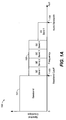
- Figs. 1a , 1b , 1c and 1d illustrate example steps performed by an SPX based audio encoder.
- Fig. 1a shows the frequency spectrum 100 of an example audio signal, wherein the frequency spectrum 100 comprises a baseband 101 (also referred to as low frequency band 101) and a high frequency band 102.
- the high frequency band 102 comprises a plurality of subbands, i.e. SE Band 1 up to SE Band 5 (SE, Spectral Extension).
- SE Band 1 up to SE Band 5 SE, Spectral Extension
- the baseband 101 comprises the lower frequencies up to the baseband cutoff frequency 103 and the high frequency band 102 comprises the high frequencies from the baseband cutoff frequency 103 up to the audio bandwidth frequency 104.
- the baseband 101 corresponds to the spectrum of a low frequency component of the audio signal and the high frequency band 102 corresponds to the spectrum of a high frequency component of the audio signal.
- the low frequency component of the audio signal comprises the frequencies within the baseband 101
- the high frequency component of the audio signal comprises the frequencies within the high frequency band 102.
- An audio encoder typically makes use of a time-domain to frequency-domain transform (e.g. a Modified Discrete Cosine Transform, MDCT and/or a Modified Discrete Sine Transform, MDST) in order to determine the spectrum 100 from the time-domain audio signal.
- a time-domain audio signal may be subdivided into a sequence of audio frames comprising respective sequences of samples of the audio signal.
- Each audio frame may be subdivided into a plurality of blocks (e.g. a plurality of up to six blocks), each block comprising e.g. N or 2N samples of the audio signal.
- the plurality of blocks of a frame may overlap (e.g. by an overlap of 50%), i.e.
- a second block may comprise a certain number of samples at its beginning, which are identical to the samples at the end of a directly preceding first block.
- a second block of 2N samples may comprise a core section of N samples, and rear/front sections of N /2 samples which overlap with the core section of the directly preceding first block and a directly succeeding third block, respectively.
- TC transform coefficients
- the time-domain to frequency-domain transform e.g.
- an MDCT or an MDST of a block of 2N samples, having a core section of N samples and overlapping rear/front sections of N /2 samples, may provide a set of N TCs .
- an overlap of 50% may result in a 1:1 relation of time-domain samples and TCs on average, thereby yielding a critically sampled system.
- a subband of the high frequency band 102 may comprise or encompass M frequency bins.
- the spectral energy of a subband may be determined based on the TCs of the M frequency bins forming the subband.
- the spectral energy of the subband may be determined based on the sum of the squared magnitude of the TCs of the M frequency bins forming the subband (e.g. based on the average of the squared magnitude of the TCs of the M frequency bins forming the subband).
- the sum of the squared magnitude of the TCs of the M frequency bins forming the subband may yield the subband power
- the subband power divided by the number M of frequency bins may yield the power spectral density (PSD).
- the baseband 101 and/or the high frequency band 102 may comprise a plurality of subbands, wherein the subbands are derived from a plurality of frequency bins, respectively.
- an SPX based encoder approximates the high frequency band 102 of an audio signal by the baseband 101 of the audio signal.
- the SPX based encoder determines side information which allows a corresponding decoder to reconstruct the high frequency band 102 from the encoded and decoded baseband 101 of the audio signal.
- the side information typically comprises indicators of the spectral energy of the one or more subbands of the high frequency band 102 (e.g. one or more energy ratios for the one or more subbands of the high frequency band 102, respectively).
- the side information typically comprises indicators of an amount of noise which is to be added to the one or more subbands of the high frequency band 102 (referred to as noise blending).
- the latter indicators are typically related to the tonality of the one or more subbands of the high frequency band 102.
- the indicators of an amount of noise which is to be added to the one or more subbands of the high frequency band 102 typically makes use of the calculation of tonality values of the one or more subbands of the high frequency band 102.
- Figs. 1b , 1c and 1d illustrate the example steps for approximating the high frequency band 102 based on the baseband 101.
- Fig. 1b shows the spectrum 110 of the low frequency component of the audio signal comprising only the baseband 101.
- Fig. 1c illustrates the spectral translation of one or more subbands 121, 122 of the baseband 101 to the frequencies of the high frequency band 102. It can be seen from the spectrum 120 that the subbands 121, 122 are copied to respective frequency bands 123, 124, 125, 126, 127 and 128 of the high frequency band 102. In the illustrated example, the subbands 121, 122 are copied three times, in order to fill up the high frequency band 102.
- Fig. 1b shows the spectrum 110 of the low frequency component of the audio signal comprising only the baseband 101.
- Fig. 1c illustrates the spectral translation of one or more subbands 121, 122 of the baseband 101 to the frequencies of the high frequency band
- FIG. 1d shows how the original high frequency band 102 of the audio signal (see Fig. 1a ) is approximated based on the copied (or translated) subbands 123, 124, 125, 126, 127 and 128.
- the SPX based audio encoder may add random noise to the copied subbands, such that the tonality of the approximated subbands 133, 134, 135, 136, 137 and 138 corresponds to the tonality of the original subbands of the high frequency band 102. This may be achieved by determining appropriate respective tonality indicators.
- the energy of the copied (and noise blended) subbands 123, 124, 125, 126, 127 and 128 may be modified such that the energy of the approximated subbands 133, 134, 135, 136, 137 and 138 corresponds to the energy of the original subbands of the high frequency band 102. This may be achieved by determining appropriate respective energy indicators. It can be seen that as a result, the spectrum 130 approximates the spectrum 100 of the original audio signal shown in Fig. 1a .
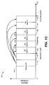
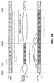
- tonality values of different signal segments may be required for a variety of purposes at different stages of the SPX encoding process. An overview of stages which typically require the determination of tonality values is shown in Figs. 2a , 2b , 2c and 2d .
- the frequency in the form of SPX subbands 0-16 is shown on the horizontal axis with markers for the SPX start band (or SPX start frequency) 201 (referred to as spxstart), the SPX begin band (or SPX begin frequency) 202 (referred to as spxbegin) and the SPX end band (or SPX end frequency) 203 (referred to as spxend).
- the SPX begin frequency 202 corresponds to the cutoff frequency 103.
- the SPX end frequency 203 may correspond to the bandwidth 104 of the original audio signal or to a frequency lower than the audio bandwidth 104 (as illustrated in Figs.
- the bandwidth of the encoded / decoded audio signal typically corresponds to the SPX end frequency 203.
- the SPX start frequency 201 corresponds to frequency bin No. 25 and the SPX end frequency 203 corresponds to frequency bin No. 229.
- the subbands of the audio signal are shown at three different stages of the SPX encoding process: The spectrum 200 (e.g. the MDCT spectrum) of the original audio signal ( Fig. 2a , top and Fig. 2b ) and the spectrum 210 of the audio signal after encoding / decoding of the low frequency component of the audio signal ( Fig. 2a , middle and Fig. 2c ).
- the encoding / decoding of the low frequency component of the audio signal may e.g. comprise matrixing and dematrixing and/or coupling and decoupling of the low frequency component.
- the spectrum 220 after spectral translation of the subbands of the baseband 101 to the high frequency band 102 is shown ( Fig 2a , bottom and Fig. 2d ).
- the spectrum 200 of the original parts of the audio signal is shown in the "Original"-line of Fig. 2a (i.e. frequency subbands 0-16); the spectrum 210 of the parts of the signal that are modified by coupling / matrixing are shown in the "Dematrixed/Decoupled Low-Band" line of Fig. 2a (i.e.
- frequency subbands 2-6 in the illustrated example frequency subbands 2-6 in the illustrated example
- spectrum 220 of the parts of the signal that are modified by spectral translation are shown in the "translated high-band" line of Fig. 2a (i.e. frequency subbands 7-14 in the illustrated example).
- the subbands 206 which are modified by the processing of the SPX based encoder are illustrated as dark shaded, whereas the subbands 205 which remain unmodified by the SPX based encoder are illustrated as light shaded.
- the braces 231, 232, 233 below the subbands and/or below groups of SPX subbands indicate for which subbands or for which groups of subbands tonality values (tonality measures) are calculated. Furthermore, it is indicated which purpose the tonality values or tonality measures are used for.
- the banded tonality values 231 i.e. the tonality values for a subband or for a group of subband
- the banded tonality values 231 i.e. the tonality values for a subband or for a group of subband
- re-send strategy typically used to steer the decision of the encoder on whether new SPX coordinates need to be transmitted or not
- the SPX coordinates typically carry information about the spectral envelope of the original audio signal in the form of gain factors for each SPX band.
- the SPX re-send strategy may indicate whether new SPX coordinates have to be transmitted for a new block of samples of the audio signal or whether the SPX coordinates for a (directly) preceding block of samples can be re-used.
- the banded tonality values 231 for the SPX bands above spxbegin 202 may be used as an input to the large variance attenuation (LVA) computations, as illustrated in Fig. 2a and Fig. 2b .
- the large variance attenuation is an encoder tool which may be used to attenuate potential errors from the spectral translation.
- the tonality values 231 may be calculated for individual subbands (e.g. subbands 0, 1,2, etc.) and/or for groups of subbands (e.g. for the group comprising subbands 11 and 12).
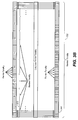
- signal tonality plays an important role for determining the amount of noise blending applied to the reconstructed subbands in the high frequency band 102.
- tonality values 232 are computed separately for the decoded (e.g. dematrixed and de-coupled) low-band and for the original high-band.
- Decoding e.g. dematrixing and de-coupling
- the previously applied encoding steps e.g. the matrixing and coupling steps
- such decoder mechanism is simulated already in the encoder.
- the low-band comprising subbands 0 - 6 of the spectrum 210 is thus a simulation of the spectrum that the decoder will recreate.
- Fig. 2c further shows that tonality is computed for two large bands (only) in this case, as opposed to the original signal's tonality which is calculated per SPX subband (which spans a multiple of 12 transform coefficients (TCs)) or per group of SPX subbands.
- the tonality values 232 are computed for a group of subbands in the baseband 101 (e.g. comprising the subbands 0 - 6) and for a group of subbands in the high frequency band 102 (e.g. comprising the subbands 7 - 14).
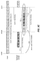
- the large variance attenuation (LVA) computations typically require another tonality input which is calculated on the translated transform coefficients (TCs). Tonality is measured for the same spectral region as in Fig. 2a , but on different data, i.e. on the translated low-band subbands, and not on the original subbands. This is depicted in the spectrum 220 shown in Fig. 2d . It can be seen that tonality values 233 are determined for subbands and/or groups of subbands within the high frequency band 102 based on the translated subbands.
- a typical SPX based encoder determines tonality values 231, 232, 233 on various subbands 205, 206 and/or groups of subbands of the original audio signal and/or of signals derived from the original audio signal in the course of the encoding / decoding process.
- tonality values 231, 232, 233 may be determined for subbands and/or groups of subbands of the original audio signal, of the encoded/decoded low frequency component of the audio signal and/or of the approximated high frequency component of the audio signal.
- the determination of tonality values 231, 232, 233 typically makes up a significant portion of the overall computational effort of an SPX based encoder. In the following, methods and systems are described which allow to significantly reduce the computational effort linked to the determination of the tonality values 231, 232, 233, thereby reducing the computational complexity of the SPX based encoder.
- the tonality value of a subband 205, 206 may be determined by analyzing the evolution of the angular velocity ⁇ (t) of the subbands 205, 206 along the time t.
- the angular velocity ⁇ (t) may be the variation of the angle or phase ⁇ over time. Consequently, the angular acceleration may be determined as the variation of the angular velocity ⁇ (t) over time, i.e. the first derivative of the angular velocity ⁇ (t), or the second derivative of the phase ⁇ .
- the subband 205, 206 is tonal, and if the angular velocity ⁇ (t) varies along the time, the subband 205, 206 is less tonal.
- the rate of change of the angular velocity ⁇ (t) i.e. the angular acceleration
- this two-step determination of the banded tonality values T q 231, 232, 233 allows for a significant reduction of the computational effort linked to the calculation of the banded tonality values T q 231,232,233.
- 2 is the squared magnitude of the transform coefficient TC of the frequency bin n at time instants k, and wherein w n,k is a weighting factor for the frequency bin n at time instant
- the tonality value T q,k 231, 232, 233 of a subband q 205, 206 or of a group of subbands q 205, 206 at a time instant k (or for a block k ) may be determined based on the tonality values T n,k of the frequency bins n at the time instant k (or for the block k ) comprised within the subband q 205, 206 or within the group of subbands q 205, 206 (e.g. based on the sum of or the average of the tonality values T n,k ).
- the time index (or block index) k and/or the bin index n / subband index q may have been omitted for conciseness reasons.
- the phase ⁇ k (for a particular bin n ) may be determined from the real and imaginary part of a complex TC.
- the complex TCs may be determined at the encoder side e.g. by performing an MDST and an MDCT transform of a block of N samples of the audio signal, thereby yielding the real part and the imaginary part of the complex TCs, respectively.
- complex time-domain to frequency-domain transforms may be used, thereby yielding complex TCs.
- the atan2 function is specified e.g.
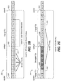
- different banded tonality values 231, 232, 233 may need to be determined based on different spectral data 200, 210, 220 derived from the original audio signal. It has been observed by the inventor based on the overview shown in Fig. 2a that different banded tonality computations are actually based on the same data, in particular based on the same transform coefficients (TCs):
- the subbands 7-14 of the high frequency band 102 are the same in the spectra 200 and 210.
- a look at Fig. 2a reveals that tonality is computed for a different band structure in both cases, even though the underlying TCs are the same.
- the computation of banded tonalities T q can be separated into calculating the per-bin tonality T n for each TC (step 1) and a subsequent process of smoothing and grouping of the bin tonality values T n into bands (step 2), thereby yielding the respective banded tonality values Tq 231, 232, 233.
- the banded tonality values Tq 231, 232, 233 may be determined based on a sum of the bin tonality values T n of the bins comprised within the band or subband of the banded tonality value, e.g. based on a weighted sum of the bin tonality values T n .
- a banded tonality value T q may be determined based on the sum of the relevant bin tonality values T n divided by the sum of the corresponding weighting factors w n . Furthermore, the determination of the banded tonality values T q may comprise a stretching and/or mapping of the (weighted) sum to a pre-determined value range (of e.g. [0,1]). From the result of step 1, arbitrary banded tonality values T q can be derived. It should be noted that the computational complexity resides mainly in step 1, which therefore makes up the efficiency gain of this two-step approach.
- each subband is made up from 12 TCs in 12 corresponding frequency bins.
- bin tonality values T n 341 are determined for the frequency bins of the subbands 7-14.
- the bin tonality values T n 341 are grouped in different ways, in order to determine the banded tonality values T q 312 (which corresponds to the banded tonality values Tq 231 in the high frequency band 102) and in order to determine the banded tonality value T q 322 (which corresponds to the banded tonality values T q 232 in the high frequency band 102).
- the computational complexity for determining the banded tonality value 322 and the banded tonality values 312 can be reduced by almost 50%, as the banded tonality values 312, 322 make use of the same bin tonality values 341.
- Fig. 3a shows that by reusing the original signal's high-band tonality also for noise blending and consequently removing the extra calculations (reference numeral 302), the number of tonality computations can be reduced.
- bin tonality values 341 can be used for determining the banded tonality values 311 (which correspond to the banded tonality values T q 231 in the baseband 101), and they can be reused for determining the banded tonality value 321 (which corresponds to the banded tonality values T q 232 in the baseband 101).
- the two-step approach for determining the banded tonality values is transparent with regards to the encoder output.
- the banded tonality values 311, 312, 321 and 322 are not affected by the two-step calculation and are therefore identical to the banded tonality values 231, 232 which are determined in a one-step calculation.
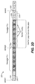
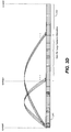
- bin tonality values 341 may also be applied in the context of spectral translation.
- Such a reuse scenario typically involves dematrixed/decoupled subbands from the baseband 101 of spectrum 210.
- a banded tonality value 321 of these subbands is computed when determining the noise blending factor b (see Fig. 3a ).
- at least some of the same TCs which are used to determine the banded tonality value 321 are used to calculate banded tonality values 233 that control the Large Variance Attenuation (LVA).
- LVA Large Variance Attenuation
- TCs are subject to spectral translation before they are used to compute the LVA tonality values 233.
- per-bin tonality T n 341 of a bin is independent from the tonality of its neighboring bins.
- per-bin tonality values T n 341 can be translated in frequency in the same way as it is done for the TCs (see Fig. 3d ). This enables the reuse of the bin tonality values T n 341 calculated in the baseband 101 for noise blending, in the computations of the LVA in the high frequency band 102. This is illustrated in Fig.
- the bin tonality values T n 341 of the frequency bins comprised within the subbands 0-5 from the baseband 101 can be reused to determine the banded tonality values T q 233.
- the computational effort for determining the banded tonality values T q 233 is significantly reduced, as illustrated by the reference numeral 303.
- the encoder output is not affected by this modified way of deriving the extension band tonality 233.
- the performance improvement resulting from the two-step approach and the reuse of bin tonality values can be quantified by comparing the number of bins for which tonality is typically computed.
- the original scheme computes tonality values for 2 ⁇ spxend - spxstart + spxend - spxbegin + 6 frequency bins (wherein the additional 6 tonality values are used to configure specific notch filters within the SPX based encoder).
- the performance gain (i.e. the complexity reduction) for the complete tonality computation is thus slightly less than the ratio of computed tonality bins which can be found in Table 2 for different bit rates.
- the two-step approach does not affect the output of the encoder.
- further measures for reducing the computational complexity of an SPX based encoder are described which might affect the output of the encoder.
- perceptual tests have shown that - in average - these further measures do not affect the perceived quality of encoded audio signals.
- the measures described below may be used alternatively or in addition to the other measures described in the present document.
- the banded tonality values T low 321 and T high 322 are the basis for the computation of the noise blending factor b .
- Tonality can be interpreted as a property which is more or less inverse to the amount of noise contained in the audio signal (i.e. more noisy ⁇ less tonal and vice versa).
- the goal of noise blending is to insert as much noise into the regenerated high-band as is necessary to make the regenerated high-band sound like the original high-band.
- the source tonality value (reflecting the tonality of the translated subbands in the high frequency band 102) and the target tonality value (reflecting the tonality of the subbands in the original high frequency band 102) should be taken into account to determine the desired target noise level. It is an observation of the inventor that the true source tonality is not correctly described by the tonality value T low 321 of the decoder-simulated low-band, but rather by a tonality value T copy 323 of the translated high-band copy (see Fig. 3c ).
- the tonality value T copy 323 may be determined based on the subbands which approximate the original subbands 7-14 of the high frequency band 102 as illustrated by the brace in Fig. 3c . It is on the translated high-band that noise blending is performed and thus only the tonality of the low-band TCs which are actually copied into the high-band should influence the amount of noise to be added.
- the tonality value T low 321 from the low-band is used as an estimate of the true source tonality. There may be two cases that influence the accuracy of this estimate:
- the use of the tonality value T low 321 may lead to an inaccurate noise blending factor b , notably in cases where not all the subbands 0-6 which are used to determine the tonality value T low 321 are translated to the high frequency band 102 (as is the case e.g. in the example shown in Fig. 3c ).
- Significant inaccuracies may occur in cases where the subbands which are not copied to the high frequency band 102 (e.g. subband 6 in Fig. 3c ) comprise significant tonal content.
- the use of the banded tonality value T copy 323 of the translated high-band may lead to a reduced computational complexity of the SPX based audio encoder. This is particularly true for the above mentioned case 2, where the translated high-band is narrower than the low-band. This benefit grows with the disparity of low-band and high-band sizes.
- the amount of bands for which source tonality is computed may be min spxbegin - spxstart , spxend - spxbegin , wherein the number ( spxbegin - spxstart) applies if the noise blending factor b is determined based on the banded tonality value T low 321 of the decoder-simulated low-band and wherein the number (spxend - spxbegin) applies if the noise blending factor b is determined based on the banded tonality value T copy 323 of the translated high-band.
- the SPX based encoder may be configured to select the mode of determination of the noise blending factor b (a first mode based on the banded tonality value T low 321 and a second mode based on the banded tonality value T copy 323), depending on the minimum of ( spxbegin - spxstart ) and ( spxend - spxbegin), thereby reducing the computational complexity (notably in cases where (spxend - spxbegin) is smaller than ( spxbegin - spxstart).
- the modified scheme for determining the noise blending factor b may be combined with the two-step approach for determining the banded tonality values T copy 323 and/or T high 322.
- the banded tonality value T copy 323 is determined based on the bin tonality values T n 341 of the frequency bins which have been translated to the high frequency band 102.
- the frequency bins contributing to the reconstructed high frequency band 102 lie between spxstart 201 and spxbegin 202. In the worst case with regards to computational complexity, all the frequency bins between spxstart 201 and spxbegin 202 contribute to the reconstructed high frequency band 102.
- the noise blending factor b is determined based on the banded tonality value T copy 323 using the bin tonality values T n 341, i.e. using the above mentioned two-step approach for determining the banded tonality value T copy 323.
- the two-step approach ensures that even in cases where (spxbegin - spxstart) is smaller than (spxend - spxbegin), the computational complexity for determining the banded tonality value T copy 323 is limited by the number of TCs comprised between ( spxbegin - spxstart ). As such, the noise blending factor b can consistently be determined based on the banded tonality value T copy 323.
- the two-step approach for determining the banded tonality values from the bin tonality values allows for a significant reuse of bin tonality values, thereby reducing the computational complexity.
- the determination of bin tonality values is mainly reduced to the determination of bin tonality values based on the spectrum 200 of the original audio signal.
- bin tonality values may need to be determined based on the coupled / decoupled spectrum 210 for some or all of the frequency bins between cplbegin 303 and spxbegin 202 (for the frequency bins of the dark shaded subbands 2-6 in Fig. 3c ).
- the only bands that may require tonality re-computation are the bands that are in coupling (see Fig. 3c ).
- Coupling usually removes the phase differences between the channels of a multi-channel signal (e.g. a stereo signal or a 5.1 multi-channel signal) that are in coupling. Frequency sharing and time sharing of the coupling coordinates further increase correlation between the coupled channels.
- the determination of tonality values is based on phases and energies of the current block of samples (at time instant k ) and of one or more preceding blocks of samples (e.g. at time instants k -1, k -2). Since the phase angles of all channels in coupling are the same (as a result of the coupling), the tonality values of those channels are more correlated than the tonality values of the original signal.
- a corresponding decoder to an SPX based encoder only has access to the de-coupled signal which the decoder generates from the received bit stream comprising encoded audio data.
- Encoding tools like noise blending and large variance attenuation (LVA) on the encoder side typically take this into account when computing ratios that intend to reproduce the original high-band signal from the transposed de-coupled low-band signal.
- the SPX based audio encoder typically takes into account that the corresponding decoder only has access to the encoded data (representative of the de-coupled audio signal).
- the source tonality for noise blending and LVA is typically computed from the de-coupled signal in current SPX based encoder (as illustrated e.g.
- a listening experiment has been conducted to evaluate the perceptual influence of using the original signal's tonality instead of the tonality of the de-coupled signal (for determining the banded tonality values 321 and 233).
- the results of the listening experiment are illustrated in Fig. 4 .
- MUSHRA MUltiple Stimuli with Hidden Reference and Anchor
- tests have been performed for a plurality of different audio signals.
- the (left hand) bars 401 indicate the results obtained when determining the tonality values based on the de-coupled signal (using spectrum 210) and the (right hand) bars 402 indicate the results obtained when determining the tonality values based on the original signal (using spectrum 200).
- the audio quality obtained when using the original audio signal for the determination of the tonality values for noise blending and for LVA is the same on average as the audio quality obtained when using the de-coupled audio signal for the determination of the tonality values.
- the results of the listening experiment of Fig. 4 suggest that the computational complexity for determining the tonality values can be further reduced by reusing the bin tonality values 341 of the original audio signal for determining the banded tonality value 321 and/or the banded tonality value 323 (used for noise blending) and the banded tonality values 233 (used for LVA).
- the computational complexity of the SPX based audio encoder can be reduced further, while not impacting (in average) the perceived audio quality of the encoded audio signals.
- the alignment of the phases due to coupling may be used to reduce the computational complexity linked to the determination of tonality.
- the decoupled signal exhibits a special property that may be used to simplify the regular tonality computation.
- the special property is that all the coupled (and subsequently de-coupled) channels are in phase.
- phase ⁇ Since all channels in coupling share the same phase ⁇ for the coupling bands, this phase ⁇ only needs to be computed once for one channel and can then be reused in the tonality computations of the other channels in coupling.
- the above mentioned formula for the bin tonality value T n,k is indicative of the acceleration of the phase angle (as outlined in the context of the formulas given for the bin tonality value T n,k above). It should be noted that other formulas for determining the bin tonality value T n , k may be used.
- the speed-up of the tonality calculations i.e. the reduction of the computational complexity
- the normalized mantissas m y , m z are within the interval [0,5;1].
- the log 2 ( x ) function in this interval may be approximated by the linear function log 2 ( x ) ⁇ 2 ⁇ x - 2 with a maximum error of 0.0861 and a mean error of 0.0573. It should be noted that other approximations (e.g. a polynomial approximation) may be possible, depending on the desired precision of the approximation and/or the computational complexity.
- the difference of the mantissa approximations still has a maximum absolute error of 0.0861, but the mean error is zero, so that the range of the maximum error changes from [0;0.0861] (positively biased) to [-0.0861;0.0861].
- the first expression 2 - int 1 4 ⁇ e y - e z + 2 ⁇ m y - 2 ⁇ m z translates to a simple shift operation towards the right by int 1 4 ⁇ e y - e z + 2 ⁇ m y - 2 ⁇ m z on a fixed point architecture.
- the second expression 2 - mod e y - e z + 2 ⁇ m y - 2 ⁇ m z 4 4 can be computed by using a pre-determined lookup table comprising powers of 2.
- the lookup table may comprise a pre-determined number of entries, in order to provide a pre-determined approximation error.
- the pre-determined lookup table may comprise a total number of 64 entries.
- the number of entries in the pre-determined lookup table should be aligned with the selected approximation of the logarithmic function.
- the precision of the quantization provided by the lookup table should be in accordance to the precision of the approximation of the logarithmic function.
- a perceptual evaluation of the above approximation method indicated that the overall quality of the encoded audio signal is improved when the estimation error of the bin tonality values is positively biased, i.e. when the approximation is more likely to overestimate the weighting factor (and the resulting tonality values) than underestimating the weighting factor.
- a bias may be added to the lookup table, e.g. a bias of half a quantization step may be added.
- a bias of half a quantization step may be implemented by truncating the index into the quantization lookup table instead of rounding the index. It may be beneficial to limit the weighting factor to 0.5, in order to match the approximation obtained by the Arabician/Heron method.
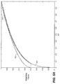
- the approximation 503 of the weighting factor w resulting from the log domain approximation function is shown in Fig. 5a , together with the bounds of its average and maximum error.
- Fig. 5a also illustrates the exact weighting factor 501 using the fourth root and the weighting factor 502 determined using the Arabician approximation.
- the perceptual quality of the log domain approximation has been verified in a listening test using the MUSHRA testing scheme. It can be seen in Fig. 5b that the perceived quality using the logarithmic approximation (left hand bars 511) is similar in average to the perceived quality using the Arabician approximation (middle bars 512) and the fourth root (right hand bars 513).
- the computational complexity of the overall tonality computation may be reduced by about 28%.
- Tonality computations have been identified as a main contributor to the computational complexity of the SPX based encoder.
- the described methods allow for a reuse of already calculated tonality values, thereby reducing the overall computational complexity.
- the reuse of already calculated tonality values typically leaves unaffected the output of the SPX based audio encoder.
- alternative ways for determining the noise blending factor b have been described which allow for a further reduction of the computational complexity.
- an efficient approximation scheme for the per-bin tonality weighting factor has been described, which may be used to reduce the complexity of the tonality computation itself without impairing the perceived audio quality.
- an overall reduction of the computational complexity for an SPX based audio encoder in the range of 50% and beyond can be expected - depending on the configuration and bit rate.
- the methods and systems described in the present document may be implemented as software, firmware and/or hardware. Certain components may e.g. be implemented as software running on a digital signal processor or microprocessor. Other components may e.g. be implemented as hardware and or as application specific integrated circuits.
- the signals encountered in the described methods and systems may be stored on media such as random access memory or optical storage media. They may be transferred via networks, such as radio networks, satellite networks, wireless networks or wireline networks, e.g. the Internet. Typical devices making use of the methods and systems described in the present document are portable electronic devices or other consumer equipment which are used to store and/or render audio signals.
Priority Applications (3)
| Application Number | Priority Date | Filing Date | Title |
|---|---|---|---|
| EP15196734.6A EP3029672B1 (en) | 2012-02-23 | 2013-02-22 | Method and program for efficient recovery of high frequency audio content |
| EP17190541.7A EP3288033B1 (en) | 2012-02-23 | 2013-02-22 | Methods and systems for efficient recovery of high frequency audio content |
| EP13705503.4A EP2817803B1 (en) | 2012-02-23 | 2013-02-22 | Methods and systems for efficient recovery of high frequency audio content |
Applications Claiming Priority (4)
| Application Number | Priority Date | Filing Date | Title |
|---|---|---|---|
| EP12156631 | 2012-02-23 | ||
| US201261680805P | 2012-08-08 | 2012-08-08 | |
| PCT/EP2013/053609 WO2013124445A2 (en) | 2012-02-23 | 2013-02-22 | Methods and systems for efficient recovery of high frequency audio content |
| EP13705503.4A EP2817803B1 (en) | 2012-02-23 | 2013-02-22 | Methods and systems for efficient recovery of high frequency audio content |
Related Child Applications (3)
| Application Number | Title | Priority Date | Filing Date |
|---|---|---|---|
| EP17190541.7A Division EP3288033B1 (en) | 2012-02-23 | 2013-02-22 | Methods and systems for efficient recovery of high frequency audio content |
| EP15196734.6A Division EP3029672B1 (en) | 2012-02-23 | 2013-02-22 | Method and program for efficient recovery of high frequency audio content |
| EP15196734.6A Division-Into EP3029672B1 (en) | 2012-02-23 | 2013-02-22 | Method and program for efficient recovery of high frequency audio content |
Publications (2)
| Publication Number | Publication Date |
|---|---|
| EP2817803A2 EP2817803A2 (en) | 2014-12-31 |
| EP2817803B1 true EP2817803B1 (en) | 2016-02-03 |
Family
ID=49006324
Family Applications (3)
| Application Number | Title | Priority Date | Filing Date |
|---|---|---|---|
| EP15196734.6A Active EP3029672B1 (en) | 2012-02-23 | 2013-02-22 | Method and program for efficient recovery of high frequency audio content |
| EP13705503.4A Active EP2817803B1 (en) | 2012-02-23 | 2013-02-22 | Methods and systems for efficient recovery of high frequency audio content |
| EP17190541.7A Active EP3288033B1 (en) | 2012-02-23 | 2013-02-22 | Methods and systems for efficient recovery of high frequency audio content |
Family Applications Before (1)
| Application Number | Title | Priority Date | Filing Date |
|---|---|---|---|
| EP15196734.6A Active EP3029672B1 (en) | 2012-02-23 | 2013-02-22 | Method and program for efficient recovery of high frequency audio content |
Family Applications After (1)
| Application Number | Title | Priority Date | Filing Date |
|---|---|---|---|
| EP17190541.7A Active EP3288033B1 (en) | 2012-02-23 | 2013-02-22 | Methods and systems for efficient recovery of high frequency audio content |
Country Status (9)
| Country | Link |
|---|---|
| US (2) | US9666200B2 (zh) |
| EP (3) | EP3029672B1 (zh) |
| JP (2) | JP6046169B2 (zh) |
| KR (2) | KR101816506B1 (zh) |
| CN (2) | CN107993673B (zh) |
| BR (2) | BR122021018240B1 (zh) |
| ES (1) | ES2568640T3 (zh) |
| RU (1) | RU2601188C2 (zh) |
| WO (1) | WO2013124445A2 (zh) |
Families Citing this family (16)
| Publication number | Priority date | Publication date | Assignee | Title |
|---|---|---|---|---|
| ES2568640T3 (es) * | 2012-02-23 | 2016-05-03 | Dolby International Ab | Procedimientos y sistemas para recuperar de manera eficiente contenido de audio de alta frecuencia |
| JP6139685B2 (ja) * | 2012-09-13 | 2017-05-31 | エルジー エレクトロニクス インコーポレイティド | 損失フレーム復元方法及びオーディオ復号化方法とそれを利用する装置 |
| EP2950308B1 (en) * | 2013-01-22 | 2020-02-19 | Panasonic Corporation | Bandwidth expansion parameter-generator, encoder, decoder, bandwidth expansion parameter-generating method, encoding method, and decoding method |
| BR122020020698B1 (pt) * | 2013-04-05 | 2022-05-31 | Dolby International Ab | Método para decodificação, meio legível por computador não transitório para decodificação, decodificador, e método de codificação de áudio para codificação em forma de onda intercalada |
| US9542955B2 (en) * | 2014-03-31 | 2017-01-10 | Qualcomm Incorporated | High-band signal coding using multiple sub-bands |
| EP2963648A1 (en) | 2014-07-01 | 2016-01-06 | Fraunhofer-Gesellschaft zur Förderung der angewandten Forschung e.V. | Audio processor and method for processing an audio signal using vertical phase correction |
| JP2016038435A (ja) * | 2014-08-06 | 2016-03-22 | ソニー株式会社 | 符号化装置および方法、復号装置および方法、並びにプログラム |
| JP6611042B2 (ja) * | 2015-12-02 | 2019-11-27 | パナソニックIpマネジメント株式会社 | 音声信号復号装置及び音声信号復号方法 |
| PL3503097T3 (pl) | 2016-01-22 | 2024-03-11 | Fraunhofer-Gesellschaft zur Förderung der angewandten Forschung e.V. | Urządzenie oraz sposób do enkodowania lub dekodowania sygnału wielokanałowego z wykorzystaniem ponownego próbkowania w dziedzinie widmowej |
| US10681679B1 (en) * | 2017-06-21 | 2020-06-09 | Nxp Usa, Inc. | Resource unit detection in high-efficiency wireless system |
| US10187721B1 (en) * | 2017-06-22 | 2019-01-22 | Amazon Technologies, Inc. | Weighing fixed and adaptive beamformers |
| US10896684B2 (en) | 2017-07-28 | 2021-01-19 | Fujitsu Limited | Audio encoding apparatus and audio encoding method |
| CN107545900B (zh) * | 2017-08-16 | 2020-12-01 | 广州广晟数码技术有限公司 | 带宽扩展编码和解码中高频弦信号生成的方法和装置 |
| TWI702594B (zh) | 2018-01-26 | 2020-08-21 | 瑞典商都比國際公司 | 用於音訊信號之高頻重建技術之回溯相容整合 |
| CN109036457B (zh) * | 2018-09-10 | 2021-10-08 | 广州酷狗计算机科技有限公司 | 恢复音频信号的方法和装置 |
| JP2023552364A (ja) * | 2020-12-31 | 2023-12-15 | 深▲セン▼市韶音科技有限公司 | オーディオ生成の方法およびシステム |
Family Cites Families (49)
| Publication number | Priority date | Publication date | Assignee | Title |
|---|---|---|---|---|
| KR920008063B1 (ko) * | 1988-11-22 | 1992-09-22 | 마쯔시다덴기산교 가부시기가이샤 | 텔레비젼신호수신장치 |
| US5699477A (en) * | 1994-11-09 | 1997-12-16 | Texas Instruments Incorporated | Mixed excitation linear prediction with fractional pitch |
| US7012630B2 (en) | 1996-02-08 | 2006-03-14 | Verizon Services Corp. | Spatial sound conference system and apparatus |
| US5913189A (en) * | 1997-02-12 | 1999-06-15 | Hughes Electronics Corporation | Voice compression system having robust in-band tone signaling and related method |
| SE9903553D0 (sv) * | 1999-01-27 | 1999-10-01 | Lars Liljeryd | Enhancing percepptual performance of SBR and related coding methods by adaptive noise addition (ANA) and noise substitution limiting (NSL) |
| JP3654117B2 (ja) * | 2000-03-13 | 2005-06-02 | ヤマハ株式会社 | 時間軸方向における楽音波形信号の伸縮方法 |
| CN1279512C (zh) * | 2001-11-29 | 2006-10-11 | 编码技术股份公司 | 用于改善高频重建的方法和装置 |
| US6978001B1 (en) | 2001-12-31 | 2005-12-20 | Cisco Technology, Inc. | Method and system for controlling audio content during multiparty communication sessions |
| EP1500084B1 (en) * | 2002-04-22 | 2008-01-23 | Koninklijke Philips Electronics N.V. | Parametric representation of spatial audio |
| TWI288915B (en) * | 2002-06-17 | 2007-10-21 | Dolby Lab Licensing Corp | Improved audio coding system using characteristics of a decoded signal to adapt synthesized spectral components |
| KR100463417B1 (ko) * | 2002-10-10 | 2004-12-23 | 한국전자통신연구원 | 상관함수의 최대값과 그의 후보값의 비를 이용한 피치검출 방법 및 그 장치 |
| WO2004036549A1 (en) | 2002-10-14 | 2004-04-29 | Koninklijke Philips Electronics N.V. | Signal filtering |
| US7318035B2 (en) * | 2003-05-08 | 2008-01-08 | Dolby Laboratories Licensing Corporation | Audio coding systems and methods using spectral component coupling and spectral component regeneration |
| JP4252417B2 (ja) * | 2003-10-02 | 2009-04-08 | 住友重機械工業株式会社 | 成形機の監視装置及び監視方法 |
| CA2454296A1 (en) | 2003-12-29 | 2005-06-29 | Nokia Corporation | Method and device for speech enhancement in the presence of background noise |
| KR100608062B1 (ko) * | 2004-08-04 | 2006-08-02 | 삼성전자주식회사 | 오디오 데이터의 고주파수 복원 방법 및 그 장치 |
| US7218240B2 (en) | 2004-08-10 | 2007-05-15 | The Boeing Company | Synthetically generated sound cues |
| US7545875B2 (en) | 2004-11-03 | 2009-06-09 | Nokia Corporation | System and method for space-time-frequency coding in a multi-antenna transmission system |
| US7675873B2 (en) | 2004-12-14 | 2010-03-09 | Alcatel Lucent | Enhanced IP-voice conferencing |
| US8082156B2 (en) * | 2005-01-11 | 2011-12-20 | Nec Corporation | Audio encoding device, audio encoding method, and audio encoding program for encoding a wide-band audio signal |
| ES2358125T3 (es) * | 2005-04-01 | 2011-05-05 | Qualcomm Incorporated | Procedimiento y aparato para un filtrado de antidispersión de una señal ensanchada de excitación de predicción de velocidad de ancho de banda. |
| US7630882B2 (en) | 2005-07-15 | 2009-12-08 | Microsoft Corporation | Frequency segmentation to obtain bands for efficient coding of digital media |
| JP4736812B2 (ja) | 2006-01-13 | 2011-07-27 | ソニー株式会社 | 信号符号化装置及び方法、信号復号装置及び方法、並びにプログラム及び記録媒体 |
| KR101240261B1 (ko) | 2006-02-07 | 2013-03-07 | 엘지전자 주식회사 | 이동통신 단말기의 영상 통화 장치 및 방법 |
| CN101149918B (zh) * | 2006-09-22 | 2012-03-28 | 鸿富锦精密工业(深圳)有限公司 | 具练唱功能的声音处理装置 |
| JP2008096567A (ja) | 2006-10-10 | 2008-04-24 | Matsushita Electric Ind Co Ltd | オーディオ符号化装置およびオーディオ符号化方法ならびにプログラム |
| WO2008100503A2 (en) * | 2007-02-12 | 2008-08-21 | Dolby Laboratories Licensing Corporation | Improved ratio of speech to non-speech audio such as for elderly or hearing-impaired listeners |
| TWI372530B (en) | 2007-03-02 | 2012-09-11 | Qualcomm Inc | Configuration of a repeater |
| JP4871894B2 (ja) * | 2007-03-02 | 2012-02-08 | パナソニック株式会社 | 符号化装置、復号装置、符号化方法および復号方法 |
| EP2210427B1 (en) | 2007-09-26 | 2015-05-06 | Fraunhofer-Gesellschaft zur Förderung der angewandten Forschung e.V. | Apparatus, method and computer program for extracting an ambient signal |
| US8509454B2 (en) | 2007-11-01 | 2013-08-13 | Nokia Corporation | Focusing on a portion of an audio scene for an audio signal |
| KR100970446B1 (ko) * | 2007-11-21 | 2010-07-16 | 한국전자통신연구원 | 주파수 확장을 위한 가변 잡음레벨 결정 장치 및 그 방법 |
| US8223851B2 (en) | 2007-11-23 | 2012-07-17 | Samsung Electronics Co., Ltd. | Method and an apparatus for embedding data in a media stream |
| CN101471072B (zh) * | 2007-12-27 | 2012-01-25 | 华为技术有限公司 | 高频重建方法、编码装置和解码装置 |
| US8532998B2 (en) * | 2008-09-06 | 2013-09-10 | Huawei Technologies Co., Ltd. | Selective bandwidth extension for encoding/decoding audio/speech signal |
| WO2010073563A1 (ja) | 2008-12-24 | 2010-07-01 | パナソニック株式会社 | 会議装置及び通信設定方法 |
| MY180550A (en) * | 2009-01-16 | 2020-12-02 | Dolby Int Ab | Cross product enhanced harmonic transposition |
| CN101527141B (zh) * | 2009-03-10 | 2011-06-22 | 苏州大学 | 基于径向基神经网络的耳语音转换为正常语音的方法 |
| EP2239732A1 (en) * | 2009-04-09 | 2010-10-13 | Fraunhofer-Gesellschaft zur Förderung der Angewandten Forschung e.V. | Apparatus and method for generating a synthesis audio signal and for encoding an audio signal |
| US8223943B2 (en) | 2009-04-14 | 2012-07-17 | Citrix Systems Inc. | Systems and methods for computer and voice conference audio transmission during conference call via PSTN phone |
| US8351589B2 (en) | 2009-06-16 | 2013-01-08 | Microsoft Corporation | Spatial audio for audio conferencing |
| US8427521B2 (en) | 2009-10-21 | 2013-04-23 | At&T Intellectual Property I, L.P. | Method and apparatus for providing a collaborative workspace |
| EP2391895B1 (en) * | 2009-11-12 | 2021-07-21 | Digital Harmonic LLC | Precision measurement of waveforms |
| US8774787B2 (en) | 2009-12-01 | 2014-07-08 | At&T Intellectual Property I, L.P. | Methods and systems for providing location-sensitive conference calling |
| GEP20146081B (en) | 2009-12-07 | 2014-04-25 | Dolby Laboratories Licensing Corp | Decoding of multichannel aufio encoded bit streams using adaptive hybrid transformation |
| US20110182415A1 (en) | 2010-01-28 | 2011-07-28 | Jacobstein Mark Williams | Methods and apparatus for providing call conferencing services |
| KR101773631B1 (ko) * | 2010-06-09 | 2017-08-31 | 파나소닉 인텔렉츄얼 프로퍼티 코포레이션 오브 아메리카 | 대역 확장 방법, 대역 확장 장치, 프로그램, 집적 회로 및 오디오 복호 장치 |
| WO2013035257A1 (ja) * | 2011-09-09 | 2013-03-14 | パナソニック株式会社 | 符号化装置、復号装置、符号化方法および復号方法 |
| ES2568640T3 (es) * | 2012-02-23 | 2016-05-03 | Dolby International Ab | Procedimientos y sistemas para recuperar de manera eficiente contenido de audio de alta frecuencia |
-
2013
- 2013-02-22 ES ES13705503.4T patent/ES2568640T3/es active Active
- 2013-02-22 KR KR1020167031826A patent/KR101816506B1/ko active IP Right Grant
- 2013-02-22 EP EP15196734.6A patent/EP3029672B1/en active Active
- 2013-02-22 US US14/372,733 patent/US9666200B2/en active Active
- 2013-02-22 CN CN201711320050.8A patent/CN107993673B/zh active Active
- 2013-02-22 EP EP13705503.4A patent/EP2817803B1/en active Active
- 2013-02-22 KR KR1020147023193A patent/KR101679209B1/ko active IP Right Grant
- 2013-02-22 WO PCT/EP2013/053609 patent/WO2013124445A2/en active Application Filing
- 2013-02-22 BR BR122021018240-0A patent/BR122021018240B1/pt active IP Right Grant
- 2013-02-22 CN CN201380010593.3A patent/CN104541327B/zh active Active
- 2013-02-22 BR BR112014020562-0A patent/BR112014020562B1/pt active IP Right Grant
- 2013-02-22 JP JP2014558129A patent/JP6046169B2/ja active Active
- 2013-02-22 RU RU2014134317/08A patent/RU2601188C2/ru active
- 2013-02-22 EP EP17190541.7A patent/EP3288033B1/en active Active
-
2016
- 2016-05-23 JP JP2016102645A patent/JP6334602B2/ja active Active
-
2017
- 2017-04-21 US US15/494,195 patent/US9984695B2/en active Active
Also Published As
| Publication number | Publication date |
|---|---|
| EP3288033A1 (en) | 2018-02-28 |
| US9666200B2 (en) | 2017-05-30 |
| JP6334602B2 (ja) | 2018-05-30 |
| BR112014020562A2 (zh) | 2017-06-20 |
| CN104541327A (zh) | 2015-04-22 |
| CN107993673B (zh) | 2022-09-27 |
| ES2568640T3 (es) | 2016-05-03 |
| CN107993673A (zh) | 2018-05-04 |
| EP3029672A3 (en) | 2016-06-29 |
| KR101816506B1 (ko) | 2018-01-09 |
| EP3288033B1 (en) | 2019-04-10 |
| US20170221491A1 (en) | 2017-08-03 |
| RU2601188C2 (ru) | 2016-10-27 |
| JP2015508186A (ja) | 2015-03-16 |
| EP3029672A2 (en) | 2016-06-08 |
| CN104541327B (zh) | 2018-01-12 |
| KR101679209B1 (ko) | 2016-12-06 |
| WO2013124445A3 (en) | 2013-11-21 |
| KR20140116520A (ko) | 2014-10-02 |
| BR112014020562B1 (pt) | 2022-06-14 |
| US9984695B2 (en) | 2018-05-29 |
| US20150003632A1 (en) | 2015-01-01 |
| EP2817803A2 (en) | 2014-12-31 |
| WO2013124445A2 (en) | 2013-08-29 |
| KR20160134871A (ko) | 2016-11-23 |
| RU2014134317A (ru) | 2016-04-20 |
| BR122021018240B1 (pt) | 2022-08-30 |
| EP3029672B1 (en) | 2017-09-13 |
| JP2016173597A (ja) | 2016-09-29 |
| JP6046169B2 (ja) | 2016-12-14 |
Similar Documents
| Publication | Publication Date | Title |
|---|---|---|
| US9984695B2 (en) | Methods and systems for efficient recovery of high frequency audio content | |
| JP6728416B2 (ja) | パラメトリック・マルチチャネル・エンコードのための方法 | |
| AU2018250490B2 (en) | Apparatus and method for efficient synthesis of sinusoids and sweeps by employing spectral patterns | |
| EP2673776B1 (en) | Apparatus and method for audio encoding and decoding employing sinusoidal substitution | |
| EP2467850B1 (en) | Method and apparatus for decoding multi-channel audio signals | |
| EP2690622B1 (en) | Audio decoding device and audio decoding method | |
| US20160210970A1 (en) | Frequency Band Table Design for High Frequency Reconstruction Algorithms |
Legal Events
| Date | Code | Title | Description |
|---|---|---|---|
| PUAI | Public reference made under article 153(3) epc to a published international application that has entered the european phase |
Free format text: ORIGINAL CODE: 0009012 |
|
| 17P | Request for examination filed |
Effective date: 20140923 |
|
| AK | Designated contracting states |
Kind code of ref document: A2 Designated state(s): AL AT BE BG CH CY CZ DE DK EE ES FI FR GB GR HR HU IE IS IT LI LT LU LV MC MK MT NL NO PL PT RO RS SE SI SK SM TR |
|
| AX | Request for extension of the european patent |
Extension state: BA ME |
|
| DAX | Request for extension of the european patent (deleted) | ||
| REG | Reference to a national code |
Ref country code: DE Ref legal event code: R079 Ref document number: 602013004925 Country of ref document: DE Free format text: PREVIOUS MAIN CLASS: G10L0021038800 Ipc: G10L0019020000 |
|
| GRAP | Despatch of communication of intention to grant a patent |
Free format text: ORIGINAL CODE: EPIDOSNIGR1 |
|
| RIC1 | Information provided on ipc code assigned before grant |
Ipc: G10L 21/0388 20130101ALI20150710BHEP Ipc: G10L 19/02 20130101AFI20150710BHEP |
|
| INTG | Intention to grant announced |
Effective date: 20150804 |
|
| GRAS | Grant fee paid |
Free format text: ORIGINAL CODE: EPIDOSNIGR3 |
|
| GRAA | (expected) grant |
Free format text: ORIGINAL CODE: 0009210 |
|
| AK | Designated contracting states |
Kind code of ref document: B1 Designated state(s): AL AT BE BG CH CY CZ DE DK EE ES FI FR GB GR HR HU IE IS IT LI LT LU LV MC MK MT NL NO PL PT RO RS SE SI SK SM TR |
|
| REG | Reference to a national code |
Ref country code: GB Ref legal event code: FG4D |
|
| REG | Reference to a national code |
Ref country code: AT Ref legal event code: REF Ref document number: 774022 Country of ref document: AT Kind code of ref document: T Effective date: 20160215 Ref country code: CH Ref legal event code: EP |
|
| REG | Reference to a national code |
Ref country code: FR Ref legal event code: PLFP Year of fee payment: 4 |
|
| REG | Reference to a national code |
Ref country code: IE Ref legal event code: FG4D |
|
| REG | Reference to a national code |
Ref country code: DE Ref legal event code: R096 Ref document number: 602013004925 Country of ref document: DE |
|
| REG | Reference to a national code |
Ref country code: ES Ref legal event code: FG2A Ref document number: 2568640 Country of ref document: ES Kind code of ref document: T3 Effective date: 20160503 |
|
| REG | Reference to a national code |
Ref country code: NL Ref legal event code: FP |
|
| REG | Reference to a national code |
Ref country code: LT Ref legal event code: MG4D |
|
| REG | Reference to a national code |
Ref country code: AT Ref legal event code: MK05 Ref document number: 774022 Country of ref document: AT Kind code of ref document: T Effective date: 20160203 |
|
| PG25 | Lapsed in a contracting state [announced via postgrant information from national office to epo] |
Ref country code: FI Free format text: LAPSE BECAUSE OF FAILURE TO SUBMIT A TRANSLATION OF THE DESCRIPTION OR TO PAY THE FEE WITHIN THE PRESCRIBED TIME-LIMIT Effective date: 20160203 Ref country code: NO Free format text: LAPSE BECAUSE OF FAILURE TO SUBMIT A TRANSLATION OF THE DESCRIPTION OR TO PAY THE FEE WITHIN THE PRESCRIBED TIME-LIMIT Effective date: 20160503 Ref country code: GR Free format text: LAPSE BECAUSE OF FAILURE TO SUBMIT A TRANSLATION OF THE DESCRIPTION OR TO PAY THE FEE WITHIN THE PRESCRIBED TIME-LIMIT Effective date: 20160504 Ref country code: HR Free format text: LAPSE BECAUSE OF FAILURE TO SUBMIT A TRANSLATION OF THE DESCRIPTION OR TO PAY THE FEE WITHIN THE PRESCRIBED TIME-LIMIT Effective date: 20160203 |
|
| PG25 | Lapsed in a contracting state [announced via postgrant information from national office to epo] |
Ref country code: BE Free format text: LAPSE BECAUSE OF NON-PAYMENT OF DUE FEES Effective date: 20160229 Ref country code: IS Free format text: LAPSE BECAUSE OF FAILURE TO SUBMIT A TRANSLATION OF THE DESCRIPTION OR TO PAY THE FEE WITHIN THE PRESCRIBED TIME-LIMIT Effective date: 20160603 Ref country code: PL Free format text: LAPSE BECAUSE OF FAILURE TO SUBMIT A TRANSLATION OF THE DESCRIPTION OR TO PAY THE FEE WITHIN THE PRESCRIBED TIME-LIMIT Effective date: 20160203 Ref country code: AT Free format text: LAPSE BECAUSE OF FAILURE TO SUBMIT A TRANSLATION OF THE DESCRIPTION OR TO PAY THE FEE WITHIN THE PRESCRIBED TIME-LIMIT Effective date: 20160203 Ref country code: LT Free format text: LAPSE BECAUSE OF FAILURE TO SUBMIT A TRANSLATION OF THE DESCRIPTION OR TO PAY THE FEE WITHIN THE PRESCRIBED TIME-LIMIT Effective date: 20160203 Ref country code: PT Free format text: LAPSE BECAUSE OF FAILURE TO SUBMIT A TRANSLATION OF THE DESCRIPTION OR TO PAY THE FEE WITHIN THE PRESCRIBED TIME-LIMIT Effective date: 20160603 Ref country code: LV Free format text: LAPSE BECAUSE OF FAILURE TO SUBMIT A TRANSLATION OF THE DESCRIPTION OR TO PAY THE FEE WITHIN THE PRESCRIBED TIME-LIMIT Effective date: 20160203 Ref country code: SE Free format text: LAPSE BECAUSE OF FAILURE TO SUBMIT A TRANSLATION OF THE DESCRIPTION OR TO PAY THE FEE WITHIN THE PRESCRIBED TIME-LIMIT Effective date: 20160203 Ref country code: RS Free format text: LAPSE BECAUSE OF FAILURE TO SUBMIT A TRANSLATION OF THE DESCRIPTION OR TO PAY THE FEE WITHIN THE PRESCRIBED TIME-LIMIT Effective date: 20160203 |
|
| REG | Reference to a national code |
Ref country code: CH Ref legal event code: PL |
|
| PG25 | Lapsed in a contracting state [announced via postgrant information from national office to epo] |
Ref country code: LI Free format text: LAPSE BECAUSE OF NON-PAYMENT OF DUE FEES Effective date: 20160229 Ref country code: CH Free format text: LAPSE BECAUSE OF NON-PAYMENT OF DUE FEES Effective date: 20160229 Ref country code: DK Free format text: LAPSE BECAUSE OF FAILURE TO SUBMIT A TRANSLATION OF THE DESCRIPTION OR TO PAY THE FEE WITHIN THE PRESCRIBED TIME-LIMIT Effective date: 20160203 Ref country code: EE Free format text: LAPSE BECAUSE OF FAILURE TO SUBMIT A TRANSLATION OF THE DESCRIPTION OR TO PAY THE FEE WITHIN THE PRESCRIBED TIME-LIMIT Effective date: 20160203 |
|
| REG | Reference to a national code |
Ref country code: DE Ref legal event code: R097 Ref document number: 602013004925 Country of ref document: DE |
|
| PG25 | Lapsed in a contracting state [announced via postgrant information from national office to epo] |
Ref country code: RO Free format text: LAPSE BECAUSE OF FAILURE TO SUBMIT A TRANSLATION OF THE DESCRIPTION OR TO PAY THE FEE WITHIN THE PRESCRIBED TIME-LIMIT Effective date: 20160203 Ref country code: CZ Free format text: LAPSE BECAUSE OF FAILURE TO SUBMIT A TRANSLATION OF THE DESCRIPTION OR TO PAY THE FEE WITHIN THE PRESCRIBED TIME-LIMIT Effective date: 20160203 Ref country code: SM Free format text: LAPSE BECAUSE OF FAILURE TO SUBMIT A TRANSLATION OF THE DESCRIPTION OR TO PAY THE FEE WITHIN THE PRESCRIBED TIME-LIMIT Effective date: 20160203 Ref country code: SK Free format text: LAPSE BECAUSE OF FAILURE TO SUBMIT A TRANSLATION OF THE DESCRIPTION OR TO PAY THE FEE WITHIN THE PRESCRIBED TIME-LIMIT Effective date: 20160203 |
|
| REG | Reference to a national code |
Ref country code: IE Ref legal event code: MM4A |
|
| PLBE | No opposition filed within time limit |
Free format text: ORIGINAL CODE: 0009261 |
|
| STAA | Information on the status of an ep patent application or granted ep patent |
Free format text: STATUS: NO OPPOSITION FILED WITHIN TIME LIMIT |
|
| PG25 | Lapsed in a contracting state [announced via postgrant information from national office to epo] |
Ref country code: BE Free format text: LAPSE BECAUSE OF FAILURE TO SUBMIT A TRANSLATION OF THE DESCRIPTION OR TO PAY THE FEE WITHIN THE PRESCRIBED TIME-LIMIT Effective date: 20160203 |
|
| 26N | No opposition filed |
Effective date: 20161104 |
|
| PG25 | Lapsed in a contracting state [announced via postgrant information from national office to epo] |
Ref country code: IE Free format text: LAPSE BECAUSE OF NON-PAYMENT OF DUE FEES Effective date: 20160222 |
|
| REG | Reference to a national code |
Ref country code: FR Ref legal event code: PLFP Year of fee payment: 5 |
|
| PG25 | Lapsed in a contracting state [announced via postgrant information from national office to epo] |
Ref country code: SI Free format text: LAPSE BECAUSE OF FAILURE TO SUBMIT A TRANSLATION OF THE DESCRIPTION OR TO PAY THE FEE WITHIN THE PRESCRIBED TIME-LIMIT Effective date: 20160203 Ref country code: BG Free format text: LAPSE BECAUSE OF FAILURE TO SUBMIT A TRANSLATION OF THE DESCRIPTION OR TO PAY THE FEE WITHIN THE PRESCRIBED TIME-LIMIT Effective date: 20160503 |
|
| PG25 | Lapsed in a contracting state [announced via postgrant information from national office to epo] |
Ref country code: MT Free format text: LAPSE BECAUSE OF FAILURE TO SUBMIT A TRANSLATION OF THE DESCRIPTION OR TO PAY THE FEE WITHIN THE PRESCRIBED TIME-LIMIT Effective date: 20160203 |
|
| REG | Reference to a national code |
Ref country code: FR Ref legal event code: PLFP Year of fee payment: 6 |
|
| PG25 | Lapsed in a contracting state [announced via postgrant information from national office to epo] |
Ref country code: HU Free format text: LAPSE BECAUSE OF FAILURE TO SUBMIT A TRANSLATION OF THE DESCRIPTION OR TO PAY THE FEE WITHIN THE PRESCRIBED TIME-LIMIT; INVALID AB INITIO Effective date: 20130222 |
|
| PG25 | Lapsed in a contracting state [announced via postgrant information from national office to epo] |
Ref country code: MK Free format text: LAPSE BECAUSE OF FAILURE TO SUBMIT A TRANSLATION OF THE DESCRIPTION OR TO PAY THE FEE WITHIN THE PRESCRIBED TIME-LIMIT Effective date: 20160203 Ref country code: MT Free format text: LAPSE BECAUSE OF FAILURE TO SUBMIT A TRANSLATION OF THE DESCRIPTION OR TO PAY THE FEE WITHIN THE PRESCRIBED TIME-LIMIT Effective date: 20160229 Ref country code: CY Free format text: LAPSE BECAUSE OF FAILURE TO SUBMIT A TRANSLATION OF THE DESCRIPTION OR TO PAY THE FEE WITHIN THE PRESCRIBED TIME-LIMIT Effective date: 20160203 Ref country code: LU Free format text: LAPSE BECAUSE OF NON-PAYMENT OF DUE FEES Effective date: 20160222 Ref country code: MC Free format text: LAPSE BECAUSE OF FAILURE TO SUBMIT A TRANSLATION OF THE DESCRIPTION OR TO PAY THE FEE WITHIN THE PRESCRIBED TIME-LIMIT Effective date: 20160203 |
|
| PG25 | Lapsed in a contracting state [announced via postgrant information from national office to epo] |
Ref country code: TR Free format text: LAPSE BECAUSE OF FAILURE TO SUBMIT A TRANSLATION OF THE DESCRIPTION OR TO PAY THE FEE WITHIN THE PRESCRIBED TIME-LIMIT Effective date: 20160203 Ref country code: AL Free format text: LAPSE BECAUSE OF FAILURE TO SUBMIT A TRANSLATION OF THE DESCRIPTION OR TO PAY THE FEE WITHIN THE PRESCRIBED TIME-LIMIT Effective date: 20160203 |
|
| REG | Reference to a national code |
Ref country code: DE Ref legal event code: R081 Ref document number: 602013004925 Country of ref document: DE Owner name: DOLBY INTERNATIONAL AB, IE Free format text: FORMER OWNER: DOLBY INTERNATIONAL AB, AMSTERDAM, NL Ref country code: DE Ref legal event code: R081 Ref document number: 602013004925 Country of ref document: DE Owner name: DOLBY INTERNATIONAL AB, NL Free format text: FORMER OWNER: DOLBY INTERNATIONAL AB, AMSTERDAM, NL |
|
| REG | Reference to a national code |
Ref country code: FR Ref legal event code: PLFP Year of fee payment: 11 |
|
| REG | Reference to a national code |
Ref country code: DE Ref legal event code: R081 Ref document number: 602013004925 Country of ref document: DE Owner name: DOLBY INTERNATIONAL AB, IE Free format text: FORMER OWNER: DOLBY INTERNATIONAL AB, DP AMSTERDAM, NL |
|
| PGFP | Annual fee paid to national office [announced via postgrant information from national office to epo] |
Ref country code: FR Payment date: 20230119 Year of fee payment: 11 Ref country code: ES Payment date: 20230301 Year of fee payment: 11 |
|
| PGFP | Annual fee paid to national office [announced via postgrant information from national office to epo] |
Ref country code: IT Payment date: 20230120 Year of fee payment: 11 |
|
| P01 | Opt-out of the competence of the unified patent court (upc) registered |
Effective date: 20230512 |
|
| PGFP | Annual fee paid to national office [announced via postgrant information from national office to epo] |
Ref country code: NL Payment date: 20240123 Year of fee payment: 12 |
|
| PGFP | Annual fee paid to national office [announced via postgrant information from national office to epo] |
Ref country code: ES Payment date: 20240301 Year of fee payment: 12 |
|
| PGFP | Annual fee paid to national office [announced via postgrant information from national office to epo] |
Ref country code: DE Payment date: 20240123 Year of fee payment: 12 Ref country code: GB Payment date: 20240123 Year of fee payment: 12 |