EP2817524B1 - Separation fastener assembly - Google Patents
Separation fastener assembly Download PDFInfo
- Publication number
- EP2817524B1 EP2817524B1 EP12869090.6A EP12869090A EP2817524B1 EP 2817524 B1 EP2817524 B1 EP 2817524B1 EP 12869090 A EP12869090 A EP 12869090A EP 2817524 B1 EP2817524 B1 EP 2817524B1
- Authority
- EP
- European Patent Office
- Prior art keywords
- fastener assembly
- nut
- energy absorbing
- separation fastener
- assembly according
- Prior art date
- Legal status (The legal status is an assumption and is not a legal conclusion. Google has not performed a legal analysis and makes no representation as to the accuracy of the status listed.)
- Active
Links
Images

Classifications
-
- F—MECHANICAL ENGINEERING; LIGHTING; HEATING; WEAPONS; BLASTING
- F16—ENGINEERING ELEMENTS AND UNITS; GENERAL MEASURES FOR PRODUCING AND MAINTAINING EFFECTIVE FUNCTIONING OF MACHINES OR INSTALLATIONS; THERMAL INSULATION IN GENERAL
- F16B—DEVICES FOR FASTENING OR SECURING CONSTRUCTIONAL ELEMENTS OR MACHINE PARTS TOGETHER, e.g. NAILS, BOLTS, CIRCLIPS, CLAMPS, CLIPS OR WEDGES; JOINTS OR JOINTING
- F16B31/00—Screwed connections specially modified in view of tensile load; Break-bolts
- F16B31/005—Breakbolts loosening due to the action of an explosive charge
-
- B—PERFORMING OPERATIONS; TRANSPORTING
- B62—LAND VEHICLES FOR TRAVELLING OTHERWISE THAN ON RAILS
- B62D—MOTOR VEHICLES; TRAILERS
- B62D21/00—Understructures, i.e. chassis frame on which a vehicle body may be mounted
- B62D21/15—Understructures, i.e. chassis frame on which a vehicle body may be mounted having impact absorbing means, e.g. a frame designed to permanently or temporarily change shape or dimension upon impact with another body
- B62D21/152—Front or rear frames
- B62D21/155—Sub-frames or underguards
-
- F—MECHANICAL ENGINEERING; LIGHTING; HEATING; WEAPONS; BLASTING
- F16—ENGINEERING ELEMENTS AND UNITS; GENERAL MEASURES FOR PRODUCING AND MAINTAINING EFFECTIVE FUNCTIONING OF MACHINES OR INSTALLATIONS; THERMAL INSULATION IN GENERAL
- F16B—DEVICES FOR FASTENING OR SECURING CONSTRUCTIONAL ELEMENTS OR MACHINE PARTS TOGETHER, e.g. NAILS, BOLTS, CIRCLIPS, CLAMPS, CLIPS OR WEDGES; JOINTS OR JOINTING
- F16B37/00—Nuts or like thread-engaging members
- F16B37/08—Quickly-detachable or mountable nuts, e.g. consisting of two or more parts; Nuts movable along the bolt after tilting the nut
- F16B37/0871—Quickly-detachable or mountable nuts, e.g. consisting of two or more parts; Nuts movable along the bolt after tilting the nut engaging the bolt laterally, i.e. without the need to engage the end of the bolt
- F16B37/0892—Quickly-detachable or mountable nuts, e.g. consisting of two or more parts; Nuts movable along the bolt after tilting the nut engaging the bolt laterally, i.e. without the need to engage the end of the bolt in two or more pieces, e.g. assemblies made by two C-shaped nuts mutually interlocked, or retained by an additional member
Definitions
- the present invention relates to a separation fastener assembly comprising a nut having a plurality of nut segments, a movable element which is movable from a first position, in which it restrains the nut segments from radial expansion, to a second position, in which it permits the nut segments to radially expand, a bolt having one end coupled to the nut, and a retaining element which is arranged to hold the nut in place.
- Separation fastener assemblies have been used for various applications and are generally responsive to a signal for releasing secured components.
- One type of separation fastener includes a pyrotechnic charge that is actuated to release the components.
- a typical assembly may include a nut having a plurality of discrete segments. The discrete segments are arranged within the fastener assembly to normally retain a bolt. When the separation fastener assembly is pyrotechnically actuated, the discrete nut segments move outward in response to an axial load on the bolt. As a result, the bolt is released.
- US 2010/0021265 A1 discloses a separation fastener assembly.
- the assembly comprises a movable element. In a first position the movable element restrain nut segments from radial expansion. In a second position the nut segments are permitted to radially expand for releasing the fastener assembly.
- a separation fastener assembly comprising a nut having a plurality of nut segments, a movable element which is movable from a first position, in which it restrains the nut segments from radial expansion, to a second position, in which it permits the nut segments to radially expand, a bolt having one end coupled to the nut, and a retaining element which is arranged to hold the nut in place, wherein the retaining element comprises an energy absorbing portion which is sleeve shaped and adapted to be permanently deformed by the movable element when the movable element is moved from the first position to the second position.
- Such a separation fastener assembly may e.g. be used to connect a structural member of a vehicle to a chassis thereof in a releasably manner.
- the separation fastener assembly is activated, e.g. by an initiator device, when there is a need to destroy the coupling function of a bolt joint system formed by the bolt and nut of the separation fastener assembly.
- the movable element is positioned in a position in which it restrains the nut segments.
- the movable element Upon activation of the separation fastener assembly the movable element is moved from this position to a position in which it no longer restrains the nut segments from radial expansion.
- the movable element may be moved by, e.g., a force generated by a pyrotechnical charge.
- energy is absorbed by the energy absorbing portion.
- the retaining element combines the function of holding the nut in place and the function of load limiting the movable element when the arrangement is activated.
- parts of the separation fastener assembly such as e.g. a housing accommodating the nut, may be subjected to high dynamical loads by the movable element.
- Such dynamical loads may be very high since a very rapid movement of the movable element is often desired and they may thus destroy e.g. a housing accommodating the nut and even separate parts from the separation fastener assembly.
- a pyrotechnical charge is used to provide a robust and rapid release of the bolt of a separation fastener assembly. Then parts of the separation fastener arrangement are subjected to high loads generated by the movement of the movable element following the detonation of the pyrotechnical charge.
- the energy absorbing portion absorbs energy when deformed in a longitudinal direction thereof by the movable element.
- the energy absorbing portion provides for load limiting of the movable element, which has the advantage that loads to parts, such as a housing accommodating the nut, during separation of the fastener assembly may be significantly reduced.
- the movable element is thus movable to the second position against a force from the energy absorbing portion. Since the energy absorbing portion is adapted to be permanently deformed, i.e. to absorb energy, the retaining element serves as a load limiter limiting the load on the housing accommodating the movable element.
- adjacent nut segments are interconnected at fracture lines, thereby forming a frangible nut.
- At least a sub portion of the energy absorbing portion is narrowing as seen in a direction from a first end to a second end thereof in order to absorb energy in an efficient manner.
- At least a sub portion of the energy absorbing portion has a progressively increasing cross section as seen in a direction from a second end to a first end thereof.
- a progressive load limiting of the movable element is thereby achieved.
- a progressive load limiting is advantageous since the risk of destroying the housing is thereby further reuced.
- At least a wall section of the energy absorbing portion is curvilinear with a radius of curvature R in the range between 3 mm and 30 mm as seen in the longitudinal direction of the retaining element.
- a sub portion of the energy absorbing portion is linearly narrowing as seen in a direction from a first end to a second end thereof.
- a sub portion of the energy absorbing portion may taper at an angle with respect to the longitudinal axis of the retaining element corresponding to an angle of 1-30 degrees. Preferably around 20 degrees.
- a first sub portion of the energy absorbing portion has a progressively increasing cross section as seen in a direction from a second end to a first end thereof and a second sub portion of the energy absorbing portion is linearly narrowing as seen in a direction from the first end to the second end thereof.
- the retaining element is arranged such that the second end of the energy absorbing portion is closest to the nut.
- the retaining element further comprises at least one tab projecting in a direction from a first end to a second end thereof, the projected tab being arranged to prevent the nut from rotational movement.
- the separation fastener assembly further comprises an actuator for initiating movement of the movable element from the first position to the second position.
- the actuator comprises a pyrotechnical charge and an igniter.
- the igniter may be adapted to receive an ignition signal from a sensor system, such as an in-crash based sensor system or a pre-crash based sensor system.
- the separation fastener assembly may be arranged in a motor vehicle for releasably connecting a structural member of the vehicle to the vehicle chassis.
- Fig. 1 shows parts of a vehicle structure 1 which comprises a front subframe 2 and a chassis 3.
- a separation fastener assembly according to an embodiment of the present invention may be arranged for releasably connecting the rear end of the front subframe 2 to the chassis 3.
- the front subframe 2 which comprises longitudinally and transversally extending structural members, is an important member of the vehicle front end structure 1a.
- the front end vehicle structure 1a further comprises collapsible longitudinal structural members 6 that are adapted to form a deformation zone 7 in which collision energy is absorbed during an impact event, such as in a collision with another vehicle or an object. Due to the deformation zone 7 the acceleration experienced by an occupant inside the passenger compartment 1b during an impact event is reduced. Consequently, the risk of injuries to the occupant(s) is reduced. In optimizing the stiffness of the front end structure 1a different load cases are considered.
- Fig. 2 shows shematically a portion of a vehicle front subframe 2 of which a rear end 2a is connected to a vehicle chassis 3 by means of a separation fastener assembly 9 according to an embodiment of the present invention.
- the separation fastener assembly 9 comprises a housing 8, a threaded bolt 10 and a nut 11, which is illustrated in Fig. 3 , having internal threads.
- the nut 11 is disposed in a cavity of the housing 8.
- the bolt 10 extends through a sleeve 2b formed at the rear end 2a of the front subframe 2 and through an aperture in the chassis 3, and is threadably engaged with the nut 11.
- the separation fastener assembly 9 further comprises a pivotable means, in the form of a lever arm 12, which at a front end 13 thereof is mounted to the rear end 2a of the front subframe 2 and at a rear end 14 thereof is mounted to the chassis 3, for assisting release of the bolt 10 from the chassis 3 when the connecting function of the fastener assembly 9 is destroyed.
- the housing 8 is attached to the vehicle chassis 3 by means of bolt connections where bolts (not shown) are extending through holes in a bottom flange of the housing 9.
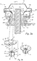
- FIG. 3 is cross sectional side view schematically illustrating the separation fastener assembly 9.
- the separation fastener assembly 9 comprises a housing 8, a nut 11, a threaded bolt 10, a movable element 17, a retaining element 19 and a lid 21.
- the bolt 10 and the nut 11 together form a bolt joint system 15.
- the nut 11 may include a plurality of nut segments connected to one another through fracture lines such that the nut 11 is a frangible nut.
- the plurality of segments may alternatively be a plurality of discrete segments.
- the nut 11 includes four nut segments 11a, 11b, 11c, 11d, as best illustrated in Fig. 3b .
- Adjacent nut segments of the nut 11 are interconnected at fracture lines and the nut segments 11a, 11b, 11c, 11d, together form a frangible nut 11.
- the frangible nut 11 may be manufactured from a powdered metal process.
- the powdered metal process may yield a nut 11 having high compression strength an low elongation values, resulting in a component having brittle characteristics.
- the nut 11 may be manufactured with any other suitable material capable of functioning as described herein.
- the movable element 17 includes a portion 23 which normally abuts a corresponding portion of the nut 11 such that the movable element 17 restrains the segments 11a, 11b, 11c, 11d of the nut 11 from radial expansion.
- the abutting portion 23 includes a protrusion, in the form of a circumferential protrusion, extending radially inward from the side wall of the movable element 17.
- the nut 11 includes a portion 25 which normally abuts a corresponding portion of the movable element 17.
- the abutting portion 25 includes a protrusion, in the form of a circumferential protrusion, extending radially outward from the side wall of the nut 11.
- a circumferential channel 22 is formed between a flange portion 27 of the movable element 17 and the housing 8, as illustrated in Fig. 3a .
- the movable element 17 is movable from a first position, in which it restrains the nut segments 11a, 11b, 11c, 11d from radial expansion, to a second position, in which it permits the nut segments 11a, 11b, 11c, 11d to radially expand.
- FIG. 3a illustrates the separation fastener assembly 9 when the nut segments 11 are prevented from radial expansion by the movable element 17, i.e. when the movable element 17 is positioned in the first position.
- the movable element 17 is arranged to hold the nut 11 in place to secure the function of the bolt joint system 15 under normal conditions.
- the retaining element 19 comprises a flat base portion 18 and a sleeve shaped energy absorbing portion 20.
- Each of the flat base portion 18 and the energy absorbing portion 20 is formed as an integral part of the retaining element 19.
- the energy absorbing portion 20 is narrowing as seen in a direction from a first end 19a to a second end 19b thereof.
- the energy absorbing portion 20 thus has a narrowing cross section as seen in a direction from the first end 19a to the second end 19b thereof, i.e. in the longitudinal direction A of the retaining element 19.
- the cross section of the energy absorbing portion 20 narrows from a large cross section at the first 19a end to a small cross section at the second end 19b, as best illustrated in Fig. 3a .
- the retaining element 19 is arranged such that the second end 19b, i.e. the end having the smaller cross section, is closest to the nut 11 and thus faces the nut 11.
- the sleeve shaped energy absorbing portion 20 may have a progressively increasing cross section as seen in a direction from the second end 19b to the first end 19a of the retaining element 19.
- at least a portion 20a of the wall of the sleeve shaped energy absorbing portion 20, as seen in a cross section is curvilinear with a radius of curvature R in the range of 3- 30mm.
- a part of the wall of the energy absorbing portion 20, as seen in a cross section is curvilinear with a radius of curvature corresponding to 8mm.
- a portion of the wall of the sleeve shaped energy absorbing portion 20b may have a cross section which tapers at an angle, as seen with respect to an axis parallel to the longitudinal axis LA of the retaining element 19, such as e.g. an angle, corresponding to an angle in the range between 1-30 degrees.
- the energy absorbing portion 20 comprises a first sub portion 20a having a cross section which is curvilinear with a radius of curvature corresponding to R8 and a second sub portion 20b having a cross section which tapers at an angle, as seen with respect to an axis parallel to the longitudinal axis LA of the retaining element 19, corresponding to an angle of 20 degrees, as illustrated in Fig. 3a .
- the energy absorbing portion 20 is arranged to be permanently deformed in its longitudinal direction by the movable element when the movable element is moved from the first position to the second position, thereby limiting the load on the housing 8.
- the energy absorbing portion 20 is formed from a plastically deformable material, such as e.g. steel.
- the movable element 17 is thus movable from the first position to a second position against a force from the energy absorbing portion 20.
- a portion of the energy absorbing portion 20 has a progressively increasing cross section as seen in the longitudinal direction thereof, i.e. in a direction from the second end 19b to the first end 19a.
- the energy absorbing portion 20 may have a uniform thickness.
- the energy absorbing portion 20 has a uniform thickness of 0.5 - 2 mm. In the embodiment described hereinbefore the energy absorbing portion 20 has a uniform thickness of 1 mm.
- the retaining element 19 comprises four downwardly extending tabs 29, of which two are visible in Fig. 3a .
- the tabs 29 are received in recesses 31 of the nut 11 and prevents the nut 11 from being rotated with respect to the housing, e.g. when the bolt 10 is tightened.
- the retaining element 19 need to be attached to the housing 8 in a rather robust manner in order to withstand the forces to which it is subjected during deformation of the energy absorbing portion 20 upon movement of the movable element to the second position.
- the retaining element 19 is attached to the housing 8 at a number of riveting joints (not shown) along the circumference of the flat base portion of the retaining element 19 by means of radial riveting.
- a base of the housing 8 reacts the torque of the nut 11 and bolt 10.
- a low level of torque may be introduced during assembly to fracture the nut 11 into the discrete segments 11a, 11b, 11c, 11d.
- the nut 11 may be pre-broken prior to activation of the assembly 9.
- the nut 11 may be fractured into the discrete segments 11a, 11b, 11c, 11d during activation.
- an initiator device comprising a pyrotechnical charge may be used to achieve a rapid movement of the movable element in case a release of the connection established by the bolt joint system 15 is desired.
- the separation fastener assembly 9 comprises an initiator device, in the form of a pyrotechnical squib 33, of a type known in the art.
- the pyrotechnical squib 33 which is carried by the housing 8, comprises a pyrotechnical charge and an electrical igniter.
- the pyrotechnical squib 33 is received in a receiving portion 35 of the housing 8, as illustrated in Fig. 2 .
- the squib 33 may have external threads that are engaged with internal threads of the receiving portion 35.
- the squib 33 is connected to a control unit 37 by means of a cable 39, as schematically illustrated in Fig. 2 .
- the receiving portion 25, and thus the squib 33 is in communication with the circumferential channel 22 through an apperture (not shown) of the housing 8. Upon ignition of the squib 33 the circumferential channel 22 is pressurized.
- the flat base portion 18 of the retaining element 19 is provided with a plurality of holes 41, as best illustrated in Fig.3b , preventing the movable element 17 from being displaced from its normal position due to e.g. pressure leakage.
- the separation fastener assembly 9 comprises a protecting lid 21, in the form of a plastic lid.
- the lid which may be formed from a thermoplastic elastomer, protects the joint bolt sytem 15 from e.g. water.
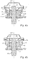
- squib 33 Upon ignition of the squib 33 (not shown in Figs. 4a-4d ) it produces a volume of gas at elevated pressure which is received in the circumferential channel 22. Due to elevated pressure inside the circumferential channel 22 a force is applied on the flange 27 of the movable element 17, thereby causing the movable element 17 to perform a movement away from the segmented nut 11, as indicated by arrows A in Fig. 4a . The movable element 17 is moved into engagement with the energy absorbing portion 20 which is then deformed by the movable element 17, as illustrated in Fig. 4b . The sleeve shaped energy absorbing portion 20 is permanently deformed by the movable element 17. Hence, the energy absorbing portion 20 absorbs impact energy of the movable element 17 during its movement toward the second position.
- the movable element 17 is moved to a second position, illustrated in Fig. 4b , in which it no longer restrains the nut segments 11a, 11b, 11c, 11d, thereby enabling movement of the nut segments 11a, 11b, 11c, 11d in radial direction.
- the bolt 10 is subjected to forces in its longitudinal direction A due to crash forces.
- the fracture lines of the frangible nut 11 are broken.
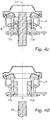
- the nut segments 11a, 11b, 11c, 11d are then separated from each other and from the bolt 10 by forces from the bolt 10, as illustrated by arrows B in Fig. 4c .
- the fracture lines are broken at this stage or they may alternatively be already pre-broken. Consequently, the connecting function of the bolt joint system 15 is destroyed which enables displacement of the bolt 10, as illustrated by the arrow C in Fig. 4d , and thereby displacement of the rear end 2a of the front subframe 2 relative to the vehicle chassis 3.
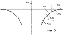
- the second embodiment differs in that the energy absorbing portion 120 comprises three linearly narrowing sub portions 120a, 120b, 120c as seen along the longitudinal axis of the retaining element 119.
- a first sub portion 120a extends from the flat base portion 118 to a second sub portion 120b of the retaining element 119.
- the second sub portion 120b extends from the first sub portion 120a to a third sub portion 120c of the energy absorbing portion 120.
- the third sub portion 120c extends from the second sub portion 120b to the second end 119b of the retaining element 119.
- the cross section of the first sub portion 120a tapers at a first angle ⁇ 1 as seen with respect to an axis parallel to the longitudinal axis LA of the retaining element 119.
- the cross section of the second sub portion tapers at a second angle ⁇ 2, as seen with respect to the longitudinal axis of the retaining element 119, which is less than the first angle.
- the cross section of the third sub portion 120c is tapering at a third angle ⁇ 3, as seen with respect to the longitudinal axis of the retaining element, which is less than the second angle ⁇ 2.
- the cross section of the first sub portion 120a tapers at a first angle ⁇ 1, as seen with respect to the longitudinal axis of the retaining element 119, corresponding to an angle of 1 - 30 degrees.
- the cross section of the second sub portion 120c tapers at a second angle ⁇ 2, as seen with respect to the longitudinal axis of the retaining element 119, corresponding to an angle of 30 - 60 degrees.
- the cross section of the third sub portion 120c tapers at a third angle ⁇ 3, as seen with respect to the longitudinal axis of the retaining element 119, corresponding to an angle in the range between 60 - 90 degrees.
- ⁇ 1 corresponds to an angle of 20 degrees, ⁇ 2 to an angle of 40 degrees and ⁇ 3 to an angle of 60 degrees.
- the movable element includes a protrusion which normally abuts the nut such that the movable element restrains the nut segments from radial expansion. It is appreciated that the movable element may include further portions which normally abut corresponding portions of the nut 11. Alternatively, the movable element may not include such a protrusion. Then, the nut need to have at least one protrusion which normally abuts the movable element.
Landscapes
- Engineering & Computer Science (AREA)
- Mechanical Engineering (AREA)
- General Engineering & Computer Science (AREA)
- Chemical & Material Sciences (AREA)
- Combustion & Propulsion (AREA)
- Transportation (AREA)
- Vibration Dampers (AREA)
Description
- The present invention relates to a separation fastener assembly comprising a nut having a plurality of nut segments, a movable element which is movable from a first position, in which it restrains the nut segments from radial expansion, to a second position, in which it permits the nut segments to radially expand, a bolt having one end coupled to the nut, and a retaining element which is arranged to hold the nut in place.
- Separation fastener assemblies have been used for various applications and are generally responsive to a signal for releasing secured components. One type of separation fastener includes a pyrotechnic charge that is actuated to release the components. A typical assembly may include a nut having a plurality of discrete segments. The discrete segments are arranged within the fastener assembly to normally retain a bolt. When the separation fastener assembly is pyrotechnically actuated, the discrete nut segments move outward in response to an axial load on the bolt. As a result, the bolt is released.
-
US 2010/0021265 A1 discloses a separation fastener assembly. The assembly comprises a movable element. In a first position the movable element restrain nut segments from radial expansion. In a second position the nut segments are permitted to radially expand for releasing the fastener assembly. - With respect to previously known solutions, it is desirable to provide a more robust separation fastener arrangement.
- It is an object of the present invention to provide a separation fastener assembly that can be made robust in a cost efficient manner.
- This and other objects that will be apparent from the following summary and description are achieved by a separation fastener arrangement according to the appended claims.
- According to an aspect of the present invention, there is provided a separation fastener assembly comprising a nut having a plurality of nut segments, a movable element which is movable from a first position, in which it restrains the nut segments from radial expansion, to a second position, in which it permits the nut segments to radially expand, a bolt having one end coupled to the nut, and a retaining element which is arranged to hold the nut in place, wherein the retaining element comprises an energy absorbing portion which is sleeve shaped and adapted to be permanently deformed by the movable element when the movable element is moved from the first position to the second position.
- Such a separation fastener assembly may e.g. be used to connect a structural member of a vehicle to a chassis thereof in a releasably manner. As long as the separation fastener assembly is not activated the movable element is held in a first position in which it secures the connecting function of the fastener assembly. The separation fastener assembly is activated, e.g. by an initiator device, when there is a need to destroy the coupling function of a bolt joint system formed by the bolt and nut of the separation fastener assembly. As long as the separation fastener assembly is not activated the movable element is positioned in a position in which it restrains the nut segments. Upon activation of the separation fastener assembly the movable element is moved from this position to a position in which it no longer restrains the nut segments from radial expansion. The movable element may be moved by, e.g., a force generated by a pyrotechnical charge. During the movement towards the second position energy is absorbed by the energy absorbing portion. Hence, the retaining element combines the function of holding the nut in place and the function of load limiting the movable element when the arrangement is activated. By this combination a separation fastener assembly that can be made robust in a cost-efficient manner is achieved.
- When the movable element is moved from the first position to a second position, parts of the separation fastener assembly, such as e.g. a housing accommodating the nut, may be subjected to high dynamical loads by the movable element. Such dynamical loads may be very high since a very rapid movement of the movable element is often desired and they may thus destroy e.g. a housing accommodating the nut and even separate parts from the separation fastener assembly. Often a pyrotechnical charge is used to provide a robust and rapid release of the bolt of a separation fastener assembly. Then parts of the separation fastener arrangement are subjected to high loads generated by the movement of the movable element following the detonation of the pyrotechnical charge.
- The energy absorbing portion absorbs energy when deformed in a longitudinal direction thereof by the movable element. Hence, the energy absorbing portion provides for load limiting of the movable element, which has the advantage that loads to parts, such as a housing accommodating the nut, during separation of the fastener assembly may be significantly reduced.
- The movable element is thus movable to the second position against a force from the energy absorbing portion. Since the energy absorbing portion is adapted to be permanently deformed, i.e. to absorb energy, the retaining element serves as a load limiter limiting the load on the housing accommodating the movable element.
- According to one embodiment adjacent nut segments are interconnected at fracture lines, thereby forming a frangible nut.
- According to the invention, at least a sub portion of the energy absorbing portion is narrowing as seen in a direction from a first end to a second end thereof in order to absorb energy in an efficient manner.
- Preferably, at least a sub portion of the energy absorbing portion has a progressively increasing cross section as seen in a direction from a second end to a first end thereof.
- In order to further enhance the energy absorbing characteristics. A progressive load limiting of the movable element is thereby achieved. A progressive load limiting is advantageous since the risk of destroying the housing is thereby further reuced.
- According to one embodiment at least a wall section of the energy absorbing portion is curvilinear with a radius of curvature R in the range between 3 mm and 30 mm as seen in the longitudinal direction of the retaining element.
- According to one embodiment a sub portion of the energy absorbing portion is linearly narrowing as seen in a direction from a first end to a second end thereof. A sub portion of the energy absorbing portion may taper at an angle with respect to the longitudinal axis of the retaining element corresponding to an angle of 1-30 degrees. Preferably around 20 degrees.
- According to one embodiment a first sub portion of the energy absorbing portion has a progressively increasing cross section as seen in a direction from a second end to a first end thereof and a second sub portion of the energy absorbing portion is linearly narrowing as seen in a direction from the first end to the second end thereof.
- According to one embodiment the retaining element is arranged such that the second end of the energy absorbing portion is closest to the nut.
- According to one embodiment the retaining element further comprises at least one tab projecting in a direction from a first end to a second end thereof, the projected tab being arranged to prevent the nut from rotational movement. This embodiment has the advantage that rotation of the nut is prevented during screwing and unscrewing of the bolt, thereby facilitate mounting of the separation fastener assembly.
- According to one embodiment the separation fastener assembly further comprises an actuator for initiating movement of the movable element from the first position to the second position. Preferably, the actuator comprises a pyrotechnical charge and an igniter.
- The igniter may be adapted to receive an ignition signal from a sensor system, such as an in-crash based sensor system or a pre-crash based sensor system.
- The separation fastener assembly may be arranged in a motor vehicle for releasably connecting a structural member of the vehicle to the vehicle chassis.
- These and other aspects of the invention will be apparent from and elucidated with reference to the claims and the embodiments described hereinafter.
- The invention will hereafter be described in more detail and with reference to the appended schematic drawings.
-
Fig. 1 is a side view of a part of motor vehicle structure. -
Fig. 2 is a schematic cross sectional view illustrating a separation fastener assembly according to one embodiment. -
Fig. 3a is a schematic cross sectional view of the separation fastener assembly shown inFig. 2 . -
Fig. 3b is a schematic perspective side view of parts of the separation fastener assembly shown inFig. 3a . -
Fig. 4a-d illustrates the function of the separation fastener assembly shown inFig. 2 and3 . -
Fig. 5 is a schematic cross sectional view of a part of a separation fastener assembly according to a second embodiment. -
Fig. 1 shows parts of a vehicle structure 1 which comprises afront subframe 2 and achassis 3. A separation fastener assembly according to an embodiment of the present invention may be arranged for releasably connecting the rear end of thefront subframe 2 to thechassis 3. Thefront subframe 2, which comprises longitudinally and transversally extending structural members, is an important member of the vehiclefront end structure 1a. The frontend vehicle structure 1a further comprises collapsible longitudinal structural members 6 that are adapted to form adeformation zone 7 in which collision energy is absorbed during an impact event, such as in a collision with another vehicle or an object. Due to thedeformation zone 7 the acceleration experienced by an occupant inside thepassenger compartment 1b during an impact event is reduced. Consequently, the risk of injuries to the occupant(s) is reduced. In optimizing the stiffness of thefront end structure 1a different load cases are considered. -
Fig. 2 shows shematically a portion of avehicle front subframe 2 of which arear end 2a is connected to avehicle chassis 3 by means of a separation fastener assembly 9 according to an embodiment of the present invention. The separation fastener assembly 9 comprises ahousing 8, a threadedbolt 10 and anut 11, which is illustrated inFig. 3 , having internal threads. Thenut 11 is disposed in a cavity of thehousing 8. Thebolt 10 extends through asleeve 2b formed at therear end 2a of thefront subframe 2 and through an aperture in thechassis 3, and is threadably engaged with thenut 11. - The separation fastener assembly 9 further comprises a pivotable means, in the form of a
lever arm 12, which at afront end 13 thereof is mounted to therear end 2a of thefront subframe 2 and at arear end 14 thereof is mounted to thechassis 3, for assisting release of thebolt 10 from thechassis 3 when the connecting function of the fastener assembly 9 is destroyed. Thehousing 8 is attached to thevehicle chassis 3 by means of bolt connections where bolts (not shown) are extending through holes in a bottom flange of the housing 9. - Now referring to
Figs. 3a and 3b the separation fastener assembly 9 will be further described.Fig. 3 is cross sectional side view schematically illustrating the separation fastener assembly 9. As illustrated inFig. 3a the separation fastener assembly 9 comprises ahousing 8, anut 11, a threadedbolt 10, amovable element 17, a retainingelement 19 and alid 21. Thebolt 10 and thenut 11 together form a boltjoint system 15. - The
nut 11 may include a plurality of nut segments connected to one another through fracture lines such that thenut 11 is a frangible nut. For other applications within the scope of the present teachings, however, the plurality of segments may alternatively be a plurality of discrete segments. In this embodiment thenut 11 includes fournut segments Fig. 3b . Adjacent nut segments of thenut 11 are interconnected at fracture lines and thenut segments frangible nut 11. Thefrangible nut 11 may be manufactured from a powdered metal process. The powdered metal process may yield anut 11 having high compression strength an low elongation values, resulting in a component having brittle characteristics. Alternatively, thenut 11 may be manufactured with any other suitable material capable of functioning as described herein. - The
movable element 17, which is formed by a collar, is arranged around thenut 11, as best illustrated inFig. 3a . Themovable element 17 includes aportion 23 which normally abuts a corresponding portion of thenut 11 such that themovable element 17 restrains thesegments nut 11 from radial expansion. The abuttingportion 23 includes a protrusion, in the form of a circumferential protrusion, extending radially inward from the side wall of themovable element 17. Thenut 11 includes aportion 25 which normally abuts a corresponding portion of themovable element 17. The abuttingportion 25 includes a protrusion, in the form of a circumferential protrusion, extending radially outward from the side wall of thenut 11. Acircumferential channel 22 is formed between aflange portion 27 of themovable element 17 and thehousing 8, as illustrated inFig. 3a . Themovable element 17 is movable from a first position, in which it restrains thenut segments nut segments Fig. 3a illustrates the separation fastener assembly 9 when thenut segments 11 are prevented from radial expansion by themovable element 17, i.e. when themovable element 17 is positioned in the first position. Themovable element 17 is arranged to hold thenut 11 in place to secure the function of the boltjoint system 15 under normal conditions. - The retaining
element 19 comprises aflat base portion 18 and a sleeve shapedenergy absorbing portion 20. Each of theflat base portion 18 and theenergy absorbing portion 20 is formed as an integral part of the retainingelement 19. Theenergy absorbing portion 20 is narrowing as seen in a direction from afirst end 19a to asecond end 19b thereof. Theenergy absorbing portion 20 thus has a narrowing cross section as seen in a direction from thefirst end 19a to thesecond end 19b thereof, i.e. in the longitudinal direction A of the retainingelement 19. Hence, the cross section of theenergy absorbing portion 20 narrows from a large cross section at the first 19a end to a small cross section at thesecond end 19b, as best illustrated inFig. 3a . The retainingelement 19 is arranged such that thesecond end 19b, i.e. the end having the smaller cross section, is closest to thenut 11 and thus faces thenut 11. - The sleeve shaped
energy absorbing portion 20 may have a progressively increasing cross section as seen in a direction from thesecond end 19b to thefirst end 19a of the retainingelement 19. Preferably, at least aportion 20a of the wall of the sleeve shapedenergy absorbing portion 20, as seen in a cross section, is curvilinear with a radius of curvature R in the range of 3- 30mm. In one embodiment a part of the wall of theenergy absorbing portion 20, as seen in a cross section, is curvilinear with a radius of curvature corresponding to 8mm. - Alternatively, or additionally, a portion of the wall of the sleeve shaped
energy absorbing portion 20b may have a cross section which tapers at an angle, as seen with respect to an axis parallel to the longitudinal axis LA of the retainingelement 19, such as e.g. an angle, corresponding to an angle in the range between 1-30 degrees. - In the embodiment shown in
Fig.3a theenergy absorbing portion 20 comprises afirst sub portion 20a having a cross section which is curvilinear with a radius of curvature corresponding to R8 and asecond sub portion 20b having a cross section which tapers at an angle, as seen with respect to an axis parallel to the longitudinal axis LA of the retainingelement 19, corresponding to an angle of 20 degrees, as illustrated inFig. 3a . - The
energy absorbing portion 20 is arranged to be permanently deformed in its longitudinal direction by the movable element when the movable element is moved from the first position to the second position, thereby limiting the load on thehousing 8. To this end theenergy absorbing portion 20 is formed from a plastically deformable material, such as e.g. steel. Themovable element 17 is thus movable from the first position to a second position against a force from theenergy absorbing portion 20. A portion of theenergy absorbing portion 20 has a progressively increasing cross section as seen in the longitudinal direction thereof, i.e. in a direction from thesecond end 19b to thefirst end 19a. - The
energy absorbing portion 20 may have a uniform thickness. Preferably theenergy absorbing portion 20 has a uniform thickness of 0.5 - 2 mm. In the embodiment described hereinbefore theenergy absorbing portion 20 has a uniform thickness of 1 mm. - The retaining
element 19 comprises four downwardly extendingtabs 29, of which two are visible inFig. 3a . Thetabs 29 are received inrecesses 31 of thenut 11 and prevents thenut 11 from being rotated with respect to the housing, e.g. when thebolt 10 is tightened. - The retaining
element 19 need to be attached to thehousing 8 in a rather robust manner in order to withstand the forces to which it is subjected during deformation of theenergy absorbing portion 20 upon movement of the movable element to the second position. In this embodiment the retainingelement 19 is attached to thehousing 8 at a number of riveting joints (not shown) along the circumference of the flat base portion of the retainingelement 19 by means of radial riveting. - Upon assembly of the separation fastener assembly, a base of the
housing 8 reacts the torque of thenut 11 andbolt 10. For certain applications, a low level of torque may be introduced during assembly to fracture thenut 11 into thediscrete segments nut 11 may be pre-broken prior to activation of the assembly 9. Alternatively, thenut 11 may be fractured into thediscrete segments - It is understood that in a crash situation it may be required to rapidly release a
bolt 10 from anut 11. The movement of themovable element 17 to the second position thus need to be carried out rapidly. To this end, an initiator device comprising a pyrotechnical charge may be used to achieve a rapid movement of the movable element in case a release of the connection established by the boltjoint system 15 is desired. - In this embodiment the separation fastener assembly 9 comprises an initiator device, in the form of a
pyrotechnical squib 33, of a type known in the art. Thepyrotechnical squib 33, which is carried by thehousing 8, comprises a pyrotechnical charge and an electrical igniter. Thepyrotechnical squib 33 is received in a receivingportion 35 of thehousing 8, as illustrated inFig. 2 . In order to fasten thesquib 33 it may have external threads that are engaged with internal threads of the receivingportion 35. Thesquib 33 is connected to acontrol unit 37 by means of acable 39, as schematically illustrated inFig. 2 . The receivingportion 25, and thus thesquib 33, is in communication with thecircumferential channel 22 through an apperture (not shown) of thehousing 8. Upon ignition of thesquib 33 thecircumferential channel 22 is pressurized. - The
flat base portion 18 of the retainingelement 19 is provided with a plurality ofholes 41, as best illustrated inFig.3b , preventing themovable element 17 from being displaced from its normal position due to e.g. pressure leakage. As described hereinbefore the separation fastener assembly 9 comprises a protectinglid 21, in the form of a plastic lid. The lid, which may be formed from a thermoplastic elastomer, protects thejoint bolt sytem 15 from e.g. water. - Now referring to
Figs. 4a-4d , the function of the separation fastener assembly 9 will be described. Upon ignition of the squib 33 (not shown inFigs. 4a-4d ) it produces a volume of gas at elevated pressure which is received in thecircumferential channel 22. Due to elevated pressure inside the circumferential channel 22 a force is applied on theflange 27 of themovable element 17, thereby causing themovable element 17 to perform a movement away from the segmentednut 11, as indicated by arrows A inFig. 4a . Themovable element 17 is moved into engagement with theenergy absorbing portion 20 which is then deformed by themovable element 17, as illustrated inFig. 4b . The sleeve shapedenergy absorbing portion 20 is permanently deformed by themovable element 17. Hence, theenergy absorbing portion 20 absorbs impact energy of themovable element 17 during its movement toward the second position. - The
movable element 17 is moved to a second position, illustrated inFig. 4b , in which it no longer restrains thenut segments nut segments bolt 10 is subjected to forces in its longitudinal direction A due to crash forces. As a result the fracture lines of thefrangible nut 11 are broken. Thenut segments bolt 10 by forces from thebolt 10, as illustrated by arrows B inFig. 4c . The fracture lines are broken at this stage or they may alternatively be already pre-broken. Consequently, the connecting function of the boltjoint system 15 is destroyed which enables displacement of thebolt 10, as illustrated by the arrow C inFig. 4d , and thereby displacement of therear end 2a of thefront subframe 2 relative to thevehicle chassis 3. - Hereinafter a separation fastener assembly according to a second embodiment of the present invention will be described with reference to
Fig. 5 . Many features disclosed in the first embodiment are also present in the second embodiment with similar reference numerals identifying similar or same features. Having mentioned this, the description will focus on explaining the differing features of the second embodiment. - The second embodiment differs in that the
energy absorbing portion 120 comprises three linearly narrowingsub portions element 119. Afirst sub portion 120a extends from theflat base portion 118 to asecond sub portion 120b of the retainingelement 119. Thesecond sub portion 120b extends from thefirst sub portion 120a to athird sub portion 120c of theenergy absorbing portion 120. Thethird sub portion 120c extends from thesecond sub portion 120b to the second end 119b of the retainingelement 119. The cross section of thefirst sub portion 120a tapers at a first angle α1 as seen with respect to an axis parallel to the longitudinal axis LA of the retainingelement 119. The cross section of the second sub portion tapers at a second angle α2, as seen with respect to the longitudinal axis of the retainingelement 119, which is less than the first angle. The cross section of thethird sub portion 120c is tapering at a third angle α3, as seen with respect to the longitudinal axis of the retaining element, which is less than the second angle α2. - Preferably, the cross section of the
first sub portion 120a tapers at a first angle α1, as seen with respect to the longitudinal axis of the retainingelement 119, corresponding to an angle of 1 - 30 degrees. - Preferably, the cross section of the
second sub portion 120c tapers at a second angle α2, as seen with respect to the longitudinal axis of the retainingelement 119, corresponding to an angle of 30 - 60 degrees. - Preferably, the cross section of the
third sub portion 120c tapers at a third angle α3, as seen with respect to the longitudinal axis of the retainingelement 119, corresponding to an angle in the range between 60 - 90 degrees. - In one embodiment α1 corresponds to an angle of 20 degrees, α2 to an angle of 40 degrees and α3 to an angle of 60 degrees.
- It is realized by a person skilled in the art that features from various embodiments disclosed herein may be combined with one another in order to provide further alternative embodiments.
- Hereinbefore, it has been described that the movable element includes a protrusion which normally abuts the nut such that the movable element restrains the nut segments from radial expansion. It is appreciated that the movable element may include further portions which normally abut corresponding portions of the
nut 11. Alternatively, the movable element may not include such a protrusion. Then, the nut need to have at least one protrusion which normally abuts the movable element.
Claims (13)
- A separation fastener assembly comprisinga nut (11) having a plurality of nut segments (11a, 11b, 11c, 11d),a movable element (17) which is movable from a first position, in which it restrains the nut segments (11a, 11b, 11c, 11d) from radial expansion, to a second position, in which it permits the nut segments (11a, 11b, 11c, 11d) to radially expand,a bolt (10) having one end coupled to the nut (11), anda retaining element (19) which is arranged to hold the nut (11) in place, cha
racterized in thatthe retaining element (19) comprises an energy absorbing portion (20) which is sleeve shaped and adapted to be permanently deformed by the movable element (17) when the movable element (17) is moved from the first position to the second position, wherein at least a sub portion (20a) of the energy absorbing portion (20) is narrowing as seen in a direction from a first end (19a) to a second end (19b) thereof. - A separation fastener assembly according to claim 1, wherein adjacent nut segments (11a, 11b, 11c, 11d) are interconnected at fracture lines, thereby forming a frangible nut (11).
- A separation fastener assembly according to any of the preceding claims, wherein at least a sub portion (20a) of the energy absorbing portion (20) has a progressively increasing cross section as seen in a direction from a second end (19b) to a first end (19a) thereof.
- A separation fastener assembly according to any of the preceding claims, wherein at least a wall section (20a) of the energy absorbing portion (20) is curvilinear with a radius of curvature R in the range between 3 mm and 30 mm as seen in the longitudinal direction of the retaining element (19).
- A separation fastener assembly according to any of the preceding claims, wherein a sub portion (20b) of the energy absorbing portion (20) is linearly narrowing as seen in a direction from a first end (19a) to a second end (19b) thereof.
- A separation fastener assembly according claim 5, wherein a sub portion (20b) of the energy absorbing portion (20) tapers at an angle (α) with respect to the longitudinal axis of the retaining element corresponding to an angle of 10-30 degrees.
- A separation fastener assembly according to any of the preceding claims wherein a first sub portion (20a) of the energy absorbing portion (20) has a progressively increasing cross section as seen in a direction from a second end (19b) to a first end thereof (19a) and a second sub portion (20b) of the energy absorbing portion (20) is linearly narrowing as seen in a direction from the first end (19a) to the second end (19b) thereof.
- A separation fastener assembly according to claim 1, wherein the retaining element is arranged such that the second end (20b) of the energy absorbing portion is closest to the nut (11).
- A separation fastener assembly according to any of the preceding claims, wherein the retaining element (19) further comprises at least one tab (29) projecting in a direction from a first end (19a) to a second end (19b) thereof, the projected tab (29) being arranged to prevent the nut (11) from rotational movement.
- A separation fastener assembly according to any of the preceding claims, further comprising an actuator (23, 37, 39) for initiating movement of the movable element (17) from the first position to the second position.
- A separation fastener assembly according to claim 10, wherein the actuator (33, 37, 39) comprises a pyrotechnical charge and an igniter (33).
- A separation fastener assembly according to claim 11, wherein the igniter (33) is adapted to receive an ignition signal from a sensor system (37), such as an in-crashbased sensor system or a pre-crash based sensor system.
- A separation fastener assembly according to any of the preceding claims arranged in a motor vehicle (1) for releasably connecting a structural member (2) of the vehicle (1) to the vehicle chassis (3).
Applications Claiming Priority (1)
| Application Number | Priority Date | Filing Date | Title |
|---|---|---|---|
| PCT/SE2012/050203 WO2013125998A1 (en) | 2012-02-23 | 2012-02-23 | Separation fastener assembly |
Publications (3)
| Publication Number | Publication Date |
|---|---|
| EP2817524A1 EP2817524A1 (en) | 2014-12-31 |
| EP2817524A4 EP2817524A4 (en) | 2015-10-14 |
| EP2817524B1 true EP2817524B1 (en) | 2019-10-02 |
Family
ID=49006049
Family Applications (1)
| Application Number | Title | Priority Date | Filing Date |
|---|---|---|---|
| EP12869090.6A Active EP2817524B1 (en) | 2012-02-23 | 2012-02-23 | Separation fastener assembly |
Country Status (2)
| Country | Link |
|---|---|
| EP (1) | EP2817524B1 (en) |
| WO (1) | WO2013125998A1 (en) |
Families Citing this family (6)
| Publication number | Priority date | Publication date | Assignee | Title |
|---|---|---|---|---|
| EP2899099B1 (en) * | 2014-01-28 | 2017-06-21 | Autoliv Development AB | An active crash structure arrangement |
| JP6218050B2 (en) * | 2016-01-19 | 2017-10-25 | 本田技研工業株式会社 | Body structure |
| CN106151225B (en) * | 2016-08-16 | 2018-06-05 | 厦门立业卫浴工业有限公司 | A kind of quick mounting nut |
| EP3676180B1 (en) | 2017-09-01 | 2022-11-02 | RUAG Space AB | Separation device for spacecraft and a method for separation |
| US11592052B2 (en) | 2018-11-27 | 2023-02-28 | Illinois Tool Works Inc. | Fastener assembly with pivoting nut |
| CN110230636B (en) * | 2019-05-15 | 2024-03-12 | 路达(厦门)工业有限公司 | Installation nut |
Family Cites Families (6)
| Publication number | Priority date | Publication date | Assignee | Title |
|---|---|---|---|---|
| FR2637252B1 (en) * | 1988-10-05 | 1990-12-28 | Aerospatiale | PROVISIONAL SOLIDARIZATION / DESOLIDARIZATION DEVICE OF TWO ELEMENTS TO EACH OTHER AND OF SUBSEQUENT SEPARATION |
| US5221171A (en) * | 1992-10-15 | 1993-06-22 | G & H Technology, Inc. | Non-explosive separation nut |
| US6352397B1 (en) * | 2000-05-31 | 2002-03-05 | Hi-Shear Technology Corporation | Reduced shock separation fastener |
| EP2143962B1 (en) * | 2008-07-07 | 2011-11-02 | Autoliv Development AB | Connecting device arranged in a motor vehicle and a method for controlling the same |
| US7862282B2 (en) * | 2008-07-24 | 2011-01-04 | Autoliv Asp, Inc. | Separation fastener with segmented washer |
| US20100021265A1 (en) * | 2008-07-24 | 2010-01-28 | Brent Parks | Separation fastener with frangible nut |
-
2012
- 2012-02-23 WO PCT/SE2012/050203 patent/WO2013125998A1/en not_active Ceased
- 2012-02-23 EP EP12869090.6A patent/EP2817524B1/en active Active
Non-Patent Citations (1)
| Title |
|---|
| None * |
Also Published As
| Publication number | Publication date |
|---|---|
| EP2817524A4 (en) | 2015-10-14 |
| EP2817524A1 (en) | 2014-12-31 |
| WO2013125998A1 (en) | 2013-08-29 |
Similar Documents
| Publication | Publication Date | Title |
|---|---|---|
| US8532881B2 (en) | Connecting device arranged in a motor vehicle and a method for controlling the same | |
| EP2817524A1 (en) | Separation fastener assembly | |
| US7896395B2 (en) | Steering column having an actuator for applying a resultant force | |
| US5193846A (en) | Air bag clamping device | |
| US7862282B2 (en) | Separation fastener with segmented washer | |
| US9114829B2 (en) | Impact absorbing steering apparatus | |
| EP2412584A1 (en) | Bumper device for vehicle | |
| EP2465751A1 (en) | Shock absorbing steering device | |
| WO2007102755A1 (en) | Arrangement for underrun protection for a vehicle | |
| US7798526B2 (en) | Steering column assembly | |
| EP1339597B1 (en) | Arrangement for weaken a construction | |
| US20160347481A1 (en) | Energy Absorbing Restraint Device | |
| US8620529B2 (en) | Sub-frame detachment through exploding bolts | |
| US5829310A (en) | Collapsible steering column | |
| EP2920475B1 (en) | Active bolt release arrangement | |
| EP1728703B1 (en) | Adaptive energy absorber for steering column | |
| US10647360B2 (en) | Vehicular structural element and vehicle body front section structure | |
| US6592283B1 (en) | Device for the embrittlement of a motor vehicle pedal pivot pin | |
| JP2009067065A (en) | Power unit mounting structure | |
| EP2899099B1 (en) | An active crash structure arrangement | |
| US10449854B2 (en) | Mounting unit comprising drive shaft and drive shaft holder as well as motor vehicle comprising mounting unit | |
| WO2009067053A1 (en) | Improvements in relating to a controlled release mechanism |
Legal Events
| Date | Code | Title | Description |
|---|---|---|---|
| PUAI | Public reference made under article 153(3) epc to a published international application that has entered the european phase |
Free format text: ORIGINAL CODE: 0009012 |
|
| 17P | Request for examination filed |
Effective date: 20140922 |
|
| AK | Designated contracting states |
Kind code of ref document: A1 Designated state(s): AL AT BE BG CH CY CZ DE DK EE ES FI FR GB GR HR HU IE IS IT LI LT LU LV MC MK MT NL NO PL PT RO RS SE SI SK SM TR |
|
| AX | Request for extension of the european patent |
Extension state: BA ME |
|
| DAX | Request for extension of the european patent (deleted) | ||
| RA4 | Supplementary search report drawn up and despatched (corrected) |
Effective date: 20150911 |
|
| RIC1 | Information provided on ipc code assigned before grant |
Ipc: F16B 37/08 20060101AFI20150907BHEP Ipc: F16B 31/00 20060101ALI20150907BHEP |
|
| GRAP | Despatch of communication of intention to grant a patent |
Free format text: ORIGINAL CODE: EPIDOSNIGR1 |
|
| STAA | Information on the status of an ep patent application or granted ep patent |
Free format text: STATUS: GRANT OF PATENT IS INTENDED |
|
| INTG | Intention to grant announced |
Effective date: 20190429 |
|
| GRAS | Grant fee paid |
Free format text: ORIGINAL CODE: EPIDOSNIGR3 |
|
| GRAA | (expected) grant |
Free format text: ORIGINAL CODE: 0009210 |
|
| STAA | Information on the status of an ep patent application or granted ep patent |
Free format text: STATUS: THE PATENT HAS BEEN GRANTED |
|
| AK | Designated contracting states |
Kind code of ref document: B1 Designated state(s): AL AT BE BG CH CY CZ DE DK EE ES FI FR GB GR HR HU IE IS IT LI LT LU LV MC MK MT NL NO PL PT RO RS SE SI SK SM TR |
|
| REG | Reference to a national code |
Ref country code: GB Ref legal event code: FG4D |
|
| REG | Reference to a national code |
Ref country code: CH Ref legal event code: EP Ref country code: AT Ref legal event code: REF Ref document number: 1186499 Country of ref document: AT Kind code of ref document: T Effective date: 20191015 |
|
| REG | Reference to a national code |
Ref country code: DE Ref legal event code: R096 Ref document number: 602012064624 Country of ref document: DE |
|
| REG | Reference to a national code |
Ref country code: IE Ref legal event code: FG4D |
|
| REG | Reference to a national code |
Ref country code: NL Ref legal event code: MP Effective date: 20191002 |
|
| REG | Reference to a national code |
Ref country code: LT Ref legal event code: MG4D |
|
| REG | Reference to a national code |
Ref country code: AT Ref legal event code: MK05 Ref document number: 1186499 Country of ref document: AT Kind code of ref document: T Effective date: 20191002 |
|
| PG25 | Lapsed in a contracting state [announced via postgrant information from national office to epo] |
Ref country code: ES Free format text: LAPSE BECAUSE OF FAILURE TO SUBMIT A TRANSLATION OF THE DESCRIPTION OR TO PAY THE FEE WITHIN THE PRESCRIBED TIME-LIMIT Effective date: 20191002 Ref country code: LV Free format text: LAPSE BECAUSE OF FAILURE TO SUBMIT A TRANSLATION OF THE DESCRIPTION OR TO PAY THE FEE WITHIN THE PRESCRIBED TIME-LIMIT Effective date: 20191002 Ref country code: SE Free format text: LAPSE BECAUSE OF FAILURE TO SUBMIT A TRANSLATION OF THE DESCRIPTION OR TO PAY THE FEE WITHIN THE PRESCRIBED TIME-LIMIT Effective date: 20191002 Ref country code: AT Free format text: LAPSE BECAUSE OF FAILURE TO SUBMIT A TRANSLATION OF THE DESCRIPTION OR TO PAY THE FEE WITHIN THE PRESCRIBED TIME-LIMIT Effective date: 20191002 Ref country code: PT Free format text: LAPSE BECAUSE OF FAILURE TO SUBMIT A TRANSLATION OF THE DESCRIPTION OR TO PAY THE FEE WITHIN THE PRESCRIBED TIME-LIMIT Effective date: 20200203 Ref country code: NO Free format text: LAPSE BECAUSE OF FAILURE TO SUBMIT A TRANSLATION OF THE DESCRIPTION OR TO PAY THE FEE WITHIN THE PRESCRIBED TIME-LIMIT Effective date: 20200102 Ref country code: BG Free format text: LAPSE BECAUSE OF FAILURE TO SUBMIT A TRANSLATION OF THE DESCRIPTION OR TO PAY THE FEE WITHIN THE PRESCRIBED TIME-LIMIT Effective date: 20200102 Ref country code: FI Free format text: LAPSE BECAUSE OF FAILURE TO SUBMIT A TRANSLATION OF THE DESCRIPTION OR TO PAY THE FEE WITHIN THE PRESCRIBED TIME-LIMIT Effective date: 20191002 Ref country code: NL Free format text: LAPSE BECAUSE OF FAILURE TO SUBMIT A TRANSLATION OF THE DESCRIPTION OR TO PAY THE FEE WITHIN THE PRESCRIBED TIME-LIMIT Effective date: 20191002 Ref country code: LT Free format text: LAPSE BECAUSE OF FAILURE TO SUBMIT A TRANSLATION OF THE DESCRIPTION OR TO PAY THE FEE WITHIN THE PRESCRIBED TIME-LIMIT Effective date: 20191002 Ref country code: GR Free format text: LAPSE BECAUSE OF FAILURE TO SUBMIT A TRANSLATION OF THE DESCRIPTION OR TO PAY THE FEE WITHIN THE PRESCRIBED TIME-LIMIT Effective date: 20200103 Ref country code: PL Free format text: LAPSE BECAUSE OF FAILURE TO SUBMIT A TRANSLATION OF THE DESCRIPTION OR TO PAY THE FEE WITHIN THE PRESCRIBED TIME-LIMIT Effective date: 20191002 |
|
| PG25 | Lapsed in a contracting state [announced via postgrant information from national office to epo] |
Ref country code: RS Free format text: LAPSE BECAUSE OF FAILURE TO SUBMIT A TRANSLATION OF THE DESCRIPTION OR TO PAY THE FEE WITHIN THE PRESCRIBED TIME-LIMIT Effective date: 20191002 Ref country code: HR Free format text: LAPSE BECAUSE OF FAILURE TO SUBMIT A TRANSLATION OF THE DESCRIPTION OR TO PAY THE FEE WITHIN THE PRESCRIBED TIME-LIMIT Effective date: 20191002 Ref country code: CZ Free format text: LAPSE BECAUSE OF FAILURE TO SUBMIT A TRANSLATION OF THE DESCRIPTION OR TO PAY THE FEE WITHIN THE PRESCRIBED TIME-LIMIT Effective date: 20191002 Ref country code: IS Free format text: LAPSE BECAUSE OF FAILURE TO SUBMIT A TRANSLATION OF THE DESCRIPTION OR TO PAY THE FEE WITHIN THE PRESCRIBED TIME-LIMIT Effective date: 20200224 |
|
| PG25 | Lapsed in a contracting state [announced via postgrant information from national office to epo] |
Ref country code: AL Free format text: LAPSE BECAUSE OF FAILURE TO SUBMIT A TRANSLATION OF THE DESCRIPTION OR TO PAY THE FEE WITHIN THE PRESCRIBED TIME-LIMIT Effective date: 20191002 |
|
| REG | Reference to a national code |
Ref country code: DE Ref legal event code: R097 Ref document number: 602012064624 Country of ref document: DE |
|
| PG2D | Information on lapse in contracting state deleted |
Ref country code: IS |
|
| PG25 | Lapsed in a contracting state [announced via postgrant information from national office to epo] |
Ref country code: RO Free format text: LAPSE BECAUSE OF FAILURE TO SUBMIT A TRANSLATION OF THE DESCRIPTION OR TO PAY THE FEE WITHIN THE PRESCRIBED TIME-LIMIT Effective date: 20191002 Ref country code: EE Free format text: LAPSE BECAUSE OF FAILURE TO SUBMIT A TRANSLATION OF THE DESCRIPTION OR TO PAY THE FEE WITHIN THE PRESCRIBED TIME-LIMIT Effective date: 20191002 Ref country code: DK Free format text: LAPSE BECAUSE OF FAILURE TO SUBMIT A TRANSLATION OF THE DESCRIPTION OR TO PAY THE FEE WITHIN THE PRESCRIBED TIME-LIMIT Effective date: 20191002 Ref country code: IS Free format text: LAPSE BECAUSE OF FAILURE TO SUBMIT A TRANSLATION OF THE DESCRIPTION OR TO PAY THE FEE WITHIN THE PRESCRIBED TIME-LIMIT Effective date: 20200202 |
|
| PLBE | No opposition filed within time limit |
Free format text: ORIGINAL CODE: 0009261 |
|
| STAA | Information on the status of an ep patent application or granted ep patent |
Free format text: STATUS: NO OPPOSITION FILED WITHIN TIME LIMIT |
|
| PG25 | Lapsed in a contracting state [announced via postgrant information from national office to epo] |
Ref country code: SK Free format text: LAPSE BECAUSE OF FAILURE TO SUBMIT A TRANSLATION OF THE DESCRIPTION OR TO PAY THE FEE WITHIN THE PRESCRIBED TIME-LIMIT Effective date: 20191002 Ref country code: SM Free format text: LAPSE BECAUSE OF FAILURE TO SUBMIT A TRANSLATION OF THE DESCRIPTION OR TO PAY THE FEE WITHIN THE PRESCRIBED TIME-LIMIT Effective date: 20191002 Ref country code: IT Free format text: LAPSE BECAUSE OF FAILURE TO SUBMIT A TRANSLATION OF THE DESCRIPTION OR TO PAY THE FEE WITHIN THE PRESCRIBED TIME-LIMIT Effective date: 20191002 |
|
| 26N | No opposition filed |
Effective date: 20200703 |
|
| REG | Reference to a national code |
Ref country code: CH Ref legal event code: PL |
|
| REG | Reference to a national code |
Ref country code: BE Ref legal event code: MM Effective date: 20200229 |
|
| PG25 | Lapsed in a contracting state [announced via postgrant information from national office to epo] |
Ref country code: LU Free format text: LAPSE BECAUSE OF NON-PAYMENT OF DUE FEES Effective date: 20200223 Ref country code: MC Free format text: LAPSE BECAUSE OF FAILURE TO SUBMIT A TRANSLATION OF THE DESCRIPTION OR TO PAY THE FEE WITHIN THE PRESCRIBED TIME-LIMIT Effective date: 20191002 |
|
| PG25 | Lapsed in a contracting state [announced via postgrant information from national office to epo] |
Ref country code: SI Free format text: LAPSE BECAUSE OF FAILURE TO SUBMIT A TRANSLATION OF THE DESCRIPTION OR TO PAY THE FEE WITHIN THE PRESCRIBED TIME-LIMIT Effective date: 20191002 Ref country code: CH Free format text: LAPSE BECAUSE OF NON-PAYMENT OF DUE FEES Effective date: 20200229 Ref country code: LI Free format text: LAPSE BECAUSE OF NON-PAYMENT OF DUE FEES Effective date: 20200229 |
|
| PG25 | Lapsed in a contracting state [announced via postgrant information from national office to epo] |
Ref country code: IE Free format text: LAPSE BECAUSE OF NON-PAYMENT OF DUE FEES Effective date: 20200223 |
|
| PG25 | Lapsed in a contracting state [announced via postgrant information from national office to epo] |
Ref country code: BE Free format text: LAPSE BECAUSE OF NON-PAYMENT OF DUE FEES Effective date: 20200229 |
|
| PG25 | Lapsed in a contracting state [announced via postgrant information from national office to epo] |
Ref country code: TR Free format text: LAPSE BECAUSE OF FAILURE TO SUBMIT A TRANSLATION OF THE DESCRIPTION OR TO PAY THE FEE WITHIN THE PRESCRIBED TIME-LIMIT Effective date: 20191002 Ref country code: MT Free format text: LAPSE BECAUSE OF FAILURE TO SUBMIT A TRANSLATION OF THE DESCRIPTION OR TO PAY THE FEE WITHIN THE PRESCRIBED TIME-LIMIT Effective date: 20191002 Ref country code: CY Free format text: LAPSE BECAUSE OF FAILURE TO SUBMIT A TRANSLATION OF THE DESCRIPTION OR TO PAY THE FEE WITHIN THE PRESCRIBED TIME-LIMIT Effective date: 20191002 |
|
| PG25 | Lapsed in a contracting state [announced via postgrant information from national office to epo] |
Ref country code: MK Free format text: LAPSE BECAUSE OF FAILURE TO SUBMIT A TRANSLATION OF THE DESCRIPTION OR TO PAY THE FEE WITHIN THE PRESCRIBED TIME-LIMIT Effective date: 20191002 |
|
| PGFP | Annual fee paid to national office [announced via postgrant information from national office to epo] |
Ref country code: GB Payment date: 20230221 Year of fee payment: 12 |
|
| P01 | Opt-out of the competence of the unified patent court (upc) registered |
Effective date: 20230507 |
|
| GBPC | Gb: european patent ceased through non-payment of renewal fee |
Effective date: 20240223 |
|
| PG25 | Lapsed in a contracting state [announced via postgrant information from national office to epo] |
Ref country code: GB Free format text: LAPSE BECAUSE OF NON-PAYMENT OF DUE FEES Effective date: 20240223 |
|
| PG25 | Lapsed in a contracting state [announced via postgrant information from national office to epo] |
Ref country code: GB Free format text: LAPSE BECAUSE OF NON-PAYMENT OF DUE FEES Effective date: 20240223 |
|
| PGFP | Annual fee paid to national office [announced via postgrant information from national office to epo] |
Ref country code: DE Payment date: 20260220 Year of fee payment: 15 |
|
| PGFP | Annual fee paid to national office [announced via postgrant information from national office to epo] |
Ref country code: FR Payment date: 20260227 Year of fee payment: 15 |