EP2817484B1 - Flow control device and method - Google Patents
Flow control device and method Download PDFInfo
- Publication number
- EP2817484B1 EP2817484B1 EP13708512.2A EP13708512A EP2817484B1 EP 2817484 B1 EP2817484 B1 EP 2817484B1 EP 13708512 A EP13708512 A EP 13708512A EP 2817484 B1 EP2817484 B1 EP 2817484B1
- Authority
- EP
- European Patent Office
- Prior art keywords
- flow
- regulator assembly
- pressure
- flow path
- compensation chamber
- Prior art date
- Legal status (The legal status is an assumption and is not a legal conclusion. Google has not performed a legal analysis and makes no representation as to the accuracy of the status listed.)
- Active
Links
Images



Classifications
-
- E—FIXED CONSTRUCTIONS
- E21—EARTH OR ROCK DRILLING; MINING
- E21B—EARTH OR ROCK DRILLING; OBTAINING OIL, GAS, WATER, SOLUBLE OR MELTABLE MATERIALS OR A SLURRY OF MINERALS FROM WELLS
- E21B47/00—Survey of boreholes or wells
- E21B47/12—Means for transmitting measuring-signals or control signals from the well to the surface, or from the surface to the well, e.g. for logging while drilling
- E21B47/14—Means for transmitting measuring-signals or control signals from the well to the surface, or from the surface to the well, e.g. for logging while drilling using acoustic waves
- E21B47/18—Means for transmitting measuring-signals or control signals from the well to the surface, or from the surface to the well, e.g. for logging while drilling using acoustic waves through the well fluid, e.g. mud pressure pulse telemetry
- E21B47/20—Means for transmitting measuring-signals or control signals from the well to the surface, or from the surface to the well, e.g. for logging while drilling using acoustic waves through the well fluid, e.g. mud pressure pulse telemetry by modulation of mud waves, e.g. by continuous modulation
-
- E—FIXED CONSTRUCTIONS
- E21—EARTH OR ROCK DRILLING; MINING
- E21B—EARTH OR ROCK DRILLING; OBTAINING OIL, GAS, WATER, SOLUBLE OR MELTABLE MATERIALS OR A SLURRY OF MINERALS FROM WELLS
- E21B43/00—Methods or apparatus for obtaining oil, gas, water, soluble or meltable materials or a slurry of minerals from wells
- E21B43/12—Methods or apparatus for controlling the flow of the obtained fluid to or in wells
-
- E—FIXED CONSTRUCTIONS
- E21—EARTH OR ROCK DRILLING; MINING
- E21B—EARTH OR ROCK DRILLING; OBTAINING OIL, GAS, WATER, SOLUBLE OR MELTABLE MATERIALS OR A SLURRY OF MINERALS FROM WELLS
- E21B34/00—Valve arrangements for boreholes or wells
- E21B34/06—Valve arrangements for boreholes or wells in wells
-
- E—FIXED CONSTRUCTIONS
- E21—EARTH OR ROCK DRILLING; MINING
- E21B—EARTH OR ROCK DRILLING; OBTAINING OIL, GAS, WATER, SOLUBLE OR MELTABLE MATERIALS OR A SLURRY OF MINERALS FROM WELLS
- E21B47/00—Survey of boreholes or wells
- E21B47/12—Means for transmitting measuring-signals or control signals from the well to the surface, or from the surface to the well, e.g. for logging while drilling
- E21B47/14—Means for transmitting measuring-signals or control signals from the well to the surface, or from the surface to the well, e.g. for logging while drilling using acoustic waves
- E21B47/18—Means for transmitting measuring-signals or control signals from the well to the surface, or from the surface to the well, e.g. for logging while drilling using acoustic waves through the well fluid, e.g. mud pressure pulse telemetry
-
- E—FIXED CONSTRUCTIONS
- E21—EARTH OR ROCK DRILLING; MINING
- E21B—EARTH OR ROCK DRILLING; OBTAINING OIL, GAS, WATER, SOLUBLE OR MELTABLE MATERIALS OR A SLURRY OF MINERALS FROM WELLS
- E21B47/00—Survey of boreholes or wells
- E21B47/12—Means for transmitting measuring-signals or control signals from the well to the surface, or from the surface to the well, e.g. for logging while drilling
- E21B47/14—Means for transmitting measuring-signals or control signals from the well to the surface, or from the surface to the well, e.g. for logging while drilling using acoustic waves
- E21B47/18—Means for transmitting measuring-signals or control signals from the well to the surface, or from the surface to the well, e.g. for logging while drilling using acoustic waves through the well fluid, e.g. mud pressure pulse telemetry
- E21B47/22—Means for transmitting measuring-signals or control signals from the well to the surface, or from the surface to the well, e.g. for logging while drilling using acoustic waves through the well fluid, e.g. mud pressure pulse telemetry by negative mud pulses using a pressure relieve valve between drill pipe and annulus
-
- E—FIXED CONSTRUCTIONS
- E21—EARTH OR ROCK DRILLING; MINING
- E21B—EARTH OR ROCK DRILLING; OBTAINING OIL, GAS, WATER, SOLUBLE OR MELTABLE MATERIALS OR A SLURRY OF MINERALS FROM WELLS
- E21B47/00—Survey of boreholes or wells
- E21B47/12—Means for transmitting measuring-signals or control signals from the well to the surface, or from the surface to the well, e.g. for logging while drilling
- E21B47/14—Means for transmitting measuring-signals or control signals from the well to the surface, or from the surface to the well, e.g. for logging while drilling using acoustic waves
- E21B47/18—Means for transmitting measuring-signals or control signals from the well to the surface, or from the surface to the well, e.g. for logging while drilling using acoustic waves through the well fluid, e.g. mud pressure pulse telemetry
- E21B47/24—Means for transmitting measuring-signals or control signals from the well to the surface, or from the surface to the well, e.g. for logging while drilling using acoustic waves through the well fluid, e.g. mud pressure pulse telemetry by positive mud pulses using a flow restricting valve within the drill pipe
-
- F—MECHANICAL ENGINEERING; LIGHTING; HEATING; WEAPONS; BLASTING
- F16—ENGINEERING ELEMENTS AND UNITS; GENERAL MEASURES FOR PRODUCING AND MAINTAINING EFFECTIVE FUNCTIONING OF MACHINES OR INSTALLATIONS; THERMAL INSULATION IN GENERAL
- F16K—VALVES; TAPS; COCKS; ACTUATING-FLOATS; DEVICES FOR VENTING OR AERATING
- F16K27/00—Construction of housing; Use of materials therefor
- F16K27/04—Construction of housing; Use of materials therefor of sliding valves
- F16K27/041—Construction of housing; Use of materials therefor of sliding valves cylindrical slide valves
-
- F—MECHANICAL ENGINEERING; LIGHTING; HEATING; WEAPONS; BLASTING
- F16—ENGINEERING ELEMENTS AND UNITS; GENERAL MEASURES FOR PRODUCING AND MAINTAINING EFFECTIVE FUNCTIONING OF MACHINES OR INSTALLATIONS; THERMAL INSULATION IN GENERAL
- F16K—VALVES; TAPS; COCKS; ACTUATING-FLOATS; DEVICES FOR VENTING OR AERATING
- F16K3/00—Gate valves or sliding valves, i.e. cut-off apparatus with closing members having a sliding movement along the seat for opening and closing
- F16K3/22—Gate valves or sliding valves, i.e. cut-off apparatus with closing members having a sliding movement along the seat for opening and closing with sealing faces shaped as surfaces of solids of revolution
- F16K3/24—Gate valves or sliding valves, i.e. cut-off apparatus with closing members having a sliding movement along the seat for opening and closing with sealing faces shaped as surfaces of solids of revolution with cylindrical valve members
- F16K3/26—Gate valves or sliding valves, i.e. cut-off apparatus with closing members having a sliding movement along the seat for opening and closing with sealing faces shaped as surfaces of solids of revolution with cylindrical valve members with fluid passages in the valve member
-
- F—MECHANICAL ENGINEERING; LIGHTING; HEATING; WEAPONS; BLASTING
- F16—ENGINEERING ELEMENTS AND UNITS; GENERAL MEASURES FOR PRODUCING AND MAINTAINING EFFECTIVE FUNCTIONING OF MACHINES OR INSTALLATIONS; THERMAL INSULATION IN GENERAL
- F16K—VALVES; TAPS; COCKS; ACTUATING-FLOATS; DEVICES FOR VENTING OR AERATING
- F16K3/00—Gate valves or sliding valves, i.e. cut-off apparatus with closing members having a sliding movement along the seat for opening and closing
- F16K3/30—Details
- F16K3/34—Arrangements for modifying the way in which the rate of flow varies during the actuation of the valve
-
- G—PHYSICS
- G01—MEASURING; TESTING
- G01V—GEOPHYSICS; GRAVITATIONAL MEASUREMENTS; DETECTING MASSES OR OBJECTS; TAGS
- G01V11/00—Prospecting or detecting by methods combining techniques covered by two or more of main groups G01V1/00 - G01V9/00
- G01V11/002—Details, e.g. power supply systems for logging instruments, transmitting or recording data, specially adapted for well logging, also if the prospecting method is irrelevant
Definitions
- the present invention relates to a flow control device and method, and in particular, but not exclusively, to a flow control device and method for imparting pressure fluctuations within a flow, such as a flow of hydrocarbons, for wireless communication.
- known installations typically require electrical supply and communication lines running the length of the production tubular from the wellhead down to the downhole monitoring and/or control system, said lines normally being secured to the production tubular using tailored clamps. Fitting cables to the tubing is a time consuming activity that prolongs the installation time.
- the cables, clamps, splices, penetrators, connectors and the like may become exposed to well fluids and are natural failure nodes. If damage occurs, the worst-case scenario is that the entire length of tubing must be retrieved to replace a damaged cable. If the damaged equipment is repairable, a well service operation must be performed.
- borehole devices such as multiphase flow meters, sand detectors, valves, chokes, circulation devices and the like may also be installed as part of a permanent borehole completion, and where this is the case similar problems as described above apply.
- the lifetime expectancy of permanent installed equipment may range from a few months to a few years, and as noted above should permanent equipment fail, the only remedy in most cases is to re-complete the well, meaning replacing the production tubular and associated systems. This operation entails high risk and cost and is generally very undesirable.
- Retrofit downhole monitoring and/or control systems are desirable in the art for use in the event of failure or compromise in permanent monitoring systems, thus permitting the continuity of dataflow from the well to be regained/maintained.
- there is a recognised desire for downhole monitoring and/or control systems that are easily installed, retrieved and maintained, in order to provide for a long-term monitoring and/or control functionality in harsh well conditions.
- WO 2006/041308 describes systems for downhole data acquisition and wireless data transmission in a well, and wireless downhole control systems enabling remote wireless flow control of downhole production and/or injection zones in a well related to the production of hydrocarbons.
- operation of a restricting valve element in the pipe flow can be used to send a wireless telegram in an oil or gas well, i.e. wireless signal transmission is achieved by transmitting pressure pulses via flowing fluid.
- wireless signal transmission is achieved by transmitting pressure pulses via flowing fluid.
- a flow control device comprising:
- the present invention may permit desired biasing of the regulator assembly to be achieved using the flowing fluid. Biasing the regulator assembly may permit appropriate operation or action in the event of failure of the drive arrangement, for example. Furthermore, biasing the regulator assembly in a desired direction may assist to minimise the power requirements of the drive arrangement. For example, minimal power requirements may be necessary when the regulator assembly is to be moved by the drive assembly in the direction of the bias.
- the effect of the present invention may be achieved by the recognition that during use the pressure varies across the first surface of the regulating assembly and thus appropriately selecting a desired localised region on the first surface from which to communicate pressure to the compensation chamber.
- the compensation chamber pressure may be determined as a function of the position of the localised region on the first surface of the regulator assembly.
- the flow control device may be configured for use with flow associated with a wellbore, such as production flow, injection flow or the like.
- the flow control device may be configured for use within a wellbore, for example at a downhole location.
- the flow control device may define a downhole flow control device.
- the regulator assembly may be moveable to vary the flow through or along the flow path.
- the regulator assembly may be moveable to vary the flow path between fully open and fully closed positions.
- the regulator assembly may be moveable to vary the flow path intermediate fully open and fully closed positions.
- the regulator assembly may be moveable to vary the flow path to impart pressure fluctuations within the flowing fluid. Such pressure fluctuations may be utilised for wireless communication within a wellbore, for example as described in WO 2006/041308 , the disclosure of which is incorporated herein by reference.
- the regulator assembly may be moveable to vary the flow path to provide choking to the flow, for example to control production/injection pressures and rates.
- the flow control device may be configurable as an inflow or outflow control device.
- the regulator assembly may be biased in a direction in which the flow path is open, for example fully open.
- the flow path may be operated and held in an open configuration in the event of, for example, failure of the drive arrangement. This may permit the flow path to remain operational in the event of such a failure, which has significant advantages in wellbore applications, for example.
- the regulator assembly may be biased in a direction in which the flow path is closed.
- the pressure which varies across the first surface will generate a force acting on the regulator assembly through said first surface, and the compensation chamber pressure will generate a force acting on the regulator assembly through said second surface, wherein the magnitude of these forces differs to establish a bias force which biases the regulator assembly in the desired direction.
- the position of the localised region of the first surface may determine the compensation chamber pressure and thus influence the magnitude of force applied on the regulator assembly through the second surface.
- a constant variation in pressure may be created over the first surface of the regulator assembly.
- a constant force may be generated on the regulator assembly through the first surface.
- the compensation chamber pressure may correlate with, for example be substantially equalised with, the pressure at the localised region of the first surface of the regulator assembly.
- the compensation chamber pressure may be substantially constant and as such a substantially constant force may be generated through the second surface.
- the flow control device may be configured to establish a bias force for all flowing conditions of fluid through the flow path. Accordingly, in use the regulator assembly may be continuously biased in the desired direction.
- the device may comprise a pressure conduit extending between the compensation chamber and the localised region of the first surface of the regulator assembly to facilitate pressure communication therebetween.
- the pressure conduit may be at least partially be provided as part of the regulator assembly.
- the pressure conduit may define a port within the first surface of the regulator assembly, such that the local pressure acting against the first surface of the regulator assembly at the location of the port is communicated to the compensation chamber.
- the pressure conduit may permit fluid communication between the flow path and the compensation chamber.
- the compensation chamber may be exposed to the fluid flowing through the flow path.
- the compensation chamber and the flow path may be fluidly isolated from each other.
- pressure communication may be achieved using a pressure transfer arrangement, such as a mellows structure, piston assembly of the like.
- the pressure variation across the first surface of the regulator assembly may be established by a flow regime of the fluid flowing through the flow path.
- the flow regime may comprise regions of lower velocity, and thus higher pressure, and regions of higher velocity, and thus lower pressure. Regions of lower velocity may be created by the fluid impinging against a surface of the flow control device, collision of different flow streams or the like.
- fluid flowing through the flow path may establish a larger pressure on a central region relative to an outer region of the first surface of the regulator assembly.
- the localised region of the first surface which is in pressure communication with the compensation chamber may be located towards the centre of the first surface.
- the localised region of the first surface which is in pressure communication with the compensation chamber may be located towards the outer region of the first surface.
- fluid flowing through the flow path may establish a larger pressure on an outer region of relative to a central region of the first surface of the regulator assembly.
- the flow control device may comprise a housing which at least partially defines the flow path.
- the housing may be at least partially defined by a tubular member.
- the housing may be configured to be mounted within a wellbore, for example via one or more tubing hangers, packers or the like.
- the housing may comprise or define at least one flow port for accommodating flow through the flow path.
- a plurality of flow ports may be provided.
- the flow ports may be distributed axially along the length of the housing.
- the flow ports may be distributed circumferentially around the housing.
- At least one flow port may be defined in or through a wall of the housing.
- At least one flow port may provide fluid communication between external and internal locations of the housing.
- At least one flow port may permit communication between the flow path and a subterranean zone, such as a production zone, injection zone or the like.
- At least one flow port may define an inlet flow port for permitting inlet flow into the flow path. Such an arrangement may have application in wellbore production flow operations. At least one flow port may define an outlet flow port for permitting outlet flow from the flow path. Such an arrangement may have application in wellbore injection flow operations.
- At least one flow port may form part of the flow path.
- the regulator assembly may cooperate with at least one flow port to vary the flow through the flow path.
- the regulator assembly may be configured to selectively block, or partially block, at least one flow port.
- Flow entering the housing via at least one flow port may establish a flow regime which creates the varying pressure across the first surface of the regulator assembly. For example, flow from at least two flow ports, for example diametrically opposing flow ports may collide to generate a region of low flow velocity and high pressure.
- At least one flow port may define a geometry to assist in creating a desired flow regime through the flow path. For example, although a variable pressure across the first surface of the regulator assembly is required, at least one flow port may define a geometry to eliminate very large variations in pressure across said first surface. At least one flow port may define a geometry to assist to minimise stagnation of flow within the flow path. At least one flow port may be obliquely aligned relative to a central axis of the housing.
- At least one flow port may define a geometry which compliments the geometry of the first surface of the regulator assembly.
- at least one flow port may define an angle which corresponds to an angle of a profile of the first surface. This arrangement may facilitate the generation or control of a desired flow regime within the flow path.
- the housing may comprise or define at least one by-pass flow port.
- the bypass-flow port may be configured to be open at all times, The by-pass flow port may not be affected by the regulator assembly.
- the by-pass flow port may permit by-pass of fluid through the flow path, for example in the event of failure of the regulator assembly, to accommodate large flow rates or the like.
- the first surface of the regulator assembly may define a geometry to assist in creating a desired flow regime and pressure distribution across said surface.
- said first surface may define a geometry which functions to eliminate very large variations in pressure across said first surface.
- the first surface may define a geometry to divert, for example gradually divert, fluid flow along the direction of the flow path.
- the first surface may define a geometry which diverts incoming flow, for example via at least one flow port, along the direction of the flow path.
- the first surface may define a geometry which gradually changes the flow direction of the flow to become aligned with the flow path. Such a geometry may minimise stagnation of flow.
- the first surface may define a conical or frusto-conical profile.
- the first surface may define a parabolic conical profile.
- the first surface may define a partially spherical surface, such as a domed surface.
- the regulator assembly may be mounted within the housing.
- the regulator assembly may be axially moveable within the housing to vary the flow path.
- the compensation chamber may be located or defined within the housing.
- the drive arrangement may be located within the housing.
- the regulator assembly may separate the flow path and the compensation chamber.
- the flow control device may comprise a sealing arrangement configured to provide a seal between the regulator assembly and the housing.
- the sealing arrangement may provide sealing between the flow path and the compensation chamber.
- the pressures acting against the respective first and second surfaces of the regulator assembly may be applied across the sealing assembly.
- the sealing assembly may define equivalent sealing areas on both sides of the regulator assembly. Alternatively, different seal areas may be provided which may contribute to generation of a bias.
- the drive arrangement may comprise a fluid drive arrangement, such as a piston arrangement.
- the drive arrangement may comprise a mechanical drive arrangement, such as a motor drive arrangement.
- the drive arrangement may function to act against the bias on the regulator assembly, for example to move the bias assembly in a direction opposing the bias.
- the flow control device may be configured to be mounted within existing equipment within a wellbore.
- the flow control device may be configured to be retrofitted within a wellbore.
- the flow control device may be configured to be installed within a wellbore as part of a wellbore completion.
- the flow control device may be configured to be installed within a wellbore using one or more of packers, hangers or the like.
- the regulator assembly may comprise a single element, wherein one side of the single element defines the first surface and an opposing side defines the second surface.
- the regulator assembly may comprise a plurality of elements.
- a method of controlling flow comprising:
- the flow control device may be configured in accordance with the first aspect. In such an arrangement features and associated methods of use of the first aspect may apply to the second aspect.
- a wireless communication assembly comprising:
- a flow control device comprising:
- a flow control device comprising:
- any effects of varying pressure which may otherwise establish an adverse bias on the regulator assembly may be minimised.
- This may therefore permit the point at which pressure is drawn or bled from the flow path to be communicated to the compensation chamber to be of less importance.
- the point at which pressure is drawn may be established on the basis of other factors, such as manufacturing simplicity and the like.
- minimising any adverse bias may facilitate low power operation of the drive arrangement.
- the first surface may define a geometry to divert, for example gradually divert, fluid flow along the direction of the flow path.
- the first surface may define a geometry which diverts incoming flow, for example via at least one flow port, along the direction of the flow path.
- the first surface may define a geometry which gradually changes the flow direction of the flow to become aligned with the flow path. Such a geometry may minimise stagnation of flow.
- the first surface may define a conical or frusto-conical profile.
- the first surface may define a parabolic conical profile.
- the first surface may define a partially spherical surface, such as a domed surface.
- the compensation chamber may be in pressure communication with the flow path via a port provided on the first surface of the regulator assembly.
- a method of controlling flow comprising:
- a flow control device comprising:
- a method of controlling flow comprising:
- a flow control device comprising:
- the flow control device may comprise a compensation chamber which is in pressure communication with the flow path, for example at a region of the first surface of the regulator assembly.
- the regulator assembly may define a second surface which is exposed to the compensation chamber.
- aspects and embodiments of the present invention relate to flow control devices and methods for controlling flow within a wellbore.
- One exemplary application of such flow control is to provide wireless communication within a wellbore. Such an exemplary application is illustrated in Figure 1
- Figure 1 illustrates a wellbore 101 which facilitates production of hydrocarbons such as oil and/or gas from a subterranean reservoir 103 via a set of perforations 102.
- hydrocarbons such as oil and/or gas
- a wellhead 104 which includes appropriate valves and monitoring systems to control and operate the well in accordance with relevant procedures and legislation.
- Downstream of the wellhead 104 the produced hydrocarbons flow through a flowline 105 to a production facility such as a separator and tank facility (not shown).
- Oil or gas fields typically comprise numerous wells, of which most/all produce into the same processing facility. As wells may be of uneven pressure, for example due to penetrating different sections of the reservoir 103 or different reservoir units, regulation is required on surface to ensure that the production from each well arrives at the production facility at equal pressure.
- most flowlines 105 are equipped with a choke valve 107 in order to regulate pressure.
- most flowlines 105 and/or wellheads 104 are equipped with a pressure sensor 106 to monitor the wellhead pressure.
- a flow control device or system 108 in accordance with aspects of the present invention is shown.
- the device 108 functions to control the flow to apply pressure signals 112 through the well fluid to provide wireless communication between the surface and downhole location.
- the device 108 can be used to monitor and/or control the well.
- the device 108 uses one or more sensors, such as a pressure sensor 111.
- a control module 110 is used to record and process the data.
- the device 108 comprises a choke/flow regulator valve or assembly 109 which is used to intelligently impose pressure variations 112 on the flowing production fluid in order to transmit the recorded data to surface.
- the pressure signals 112 are received by a sensor such as a pressure sensor 106 and an analysis system (not shown) is used to extract the downhole information.
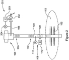
- Figure 2 illustrates a wellbore which is largely similar to that shown in Figure 1 , and as such like components share like reference numerals. However, the arrangement shown in Figure 2 differs in that a flow control device or system 201, which is configured similarly to downhole device 108, is provided at the surface location (effectively replacing or modifying the choke 107 in Figure 1 ) and which is used for receiving signals 112 transmitted from the downhole device 108 as well as transmitting pressure signals 205 to said downhole device 108.
- a flow control device or system 201 which is configured similarly to downhole device 108, is provided at the surface location (effectively replacing or modifying the choke 107 in Figure 1 ) and which is used for receiving signals 112 transmitted from the downhole device 108 as well as transmitting pressure signals 205 to said downhole device 108.
- FIG. 3 there is shown one embodiment of a flow control device or system 108 which may be used to monitor downhole conditions, such as pressure and temperature data, and transmit such data wirelessly to surface by means of imposing pressure pulses onto the flowing fluid in the well.
- the device 108 functions in a similar manner to that described in WO 2006/041308 , the disclosure of which is incorporated herein by reference.
- the device 108 which includes the choke/flow regulator valve or assembly 109, includes a housing 210 which is secured to the well/production tubing 101 by means of a packer arrangement 212.
- the packer arrangement 212 restricts the fluid flow 216, which can be both produced as well as injected fluids, along the tubing 101 causing flow through flow ports 218 formed in the wall of the housing 210 and into a flow path 214 which is in fluid communication with surface.
- a regulator assembly or element 220 is mounted within the housing 210 and is actuated to move by a drive arrangement 222 to vary the flow area through the ports 218 and into the flow path 214 to generate pressure based wireless signals which are then transmitted via the fluid to surface.
- the regulator assembly 220 is sealed against the inner surface of the housing and includes a first surface 224 which is exposed to the flow path 214 and a second opposing surface 226 which is exposed to a compensation chamber 228.
- a desired interaction between the surfaces 224, 226 and the pressures within the flow path 214 and the compensation chamber 228 provides biasing of the regulator assembly 22 in a desired direction.
- the regulator assembly is biased in a direction in which the flow ports 218 are fully opened. This may therefore assist to provide a fail-safe measure in the event of, for example, failure of the drive arrangement 222.
- the compensation chamber 228 may be provided to prevent hydraulic lock of the regulator assembly during use. Further, as will be described in detail below, the compensation chamber 228 is in pressure communication with the flow path 214 such that the pressure differential across the regulator assembly 220 is generally minimised. This may assist to minimise the power requirements of the drive arrangement 222 to move the regulator assembly 220.
- the drive arrangement 222 which is also mounted within the housing, comprises an electric motor 230 which operates a pump 232 to displace a fluid to/from a piston chamber 234 in order to apply work on a drive piston 236 secured to the regulator assembly 220 via shaft 238.
- a battery module 240 and an control/electronics module 242 are used to energise and control the operation of the device 108.
- Pressure bulk heads 244 are utilised to protect the battery module 240 and control/electronic module 242 from process/well pressure.
- the motor 230 is used to operate the pump 232 to pump fluid into a piston chamber 234 to cause the drive piston 236 and regulator assembly 220 (via shaft 238) to shift to the right in Figure 3 .
- This has the effect of reducing the flow area through the flow ports 218 thus choking the flow and generating a pressure drawdown downstream of the device 108.
- the motor 230 is reversed to offload fluids from the piston chamber 234.
- a spring 246 causes the regulator assembly 220 to retract and the production returns to "normal", i.e. a fully open position.
- the relatively violent flow regime that is present in oil and gas wells may adversely affect the operation of the device.
- flow effects in the form of local pressure variations as a result of flow rate variations may apply adverse biasing forces on the regulator assembly 220.
- forces created by fluid dynamic forces such as ejector effects may overcome the force of the spring 246 and cause malfunction. Ejector effects may also overcome the force created by the pump 232 working on the piston 236.
- oil and gas wells may experience scale formation that may cause friction and entail a larger power requirement to operate the device 108.
- the present invention seeks to address such issues by mitigating or alleviating undesirable biasing effects and/or permitting lower power operation.
- FIG. 4 there is shown an enlarged view of the flow control device 108 in Figure 3 in the region of the choke/flow regulator valve or assembly 109.
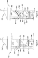
- the present inventors have recognised that the flow regime created by fluid flowing through the flow ports 218 and into the flow path 214 establishes a pressure which varies across the first surface of the regulator assembly 220. Specifically, the central region of the first surface 224 receives a higher pressure than the peripheral region of the first surface 224, as illustrated in the superimposed pressure plot 250.
- the present inventors consider this effect to be a consequence of flow streams from opposing flow ports 218 colliding in a central region of the flow path 214 thus creating a central region of low velocity and thus higher pressure, relative to the peripheral region.
- the force applied on the regulator assembly 220 via the first surface 224 will thus be a function of this variable pressure.
- the regulator assembly 220 defines a pressure conduit 252 which provides pressure communication between a localised region 254 of the first surface 224 and the compensation chamber 228. Accordingly, the pressure within the compensation chamber 228 will be substantially equalised with the pressure acting at the localised region 254 of the first surface 224, and as such this pressure will be applied substantially uniformly over the second surface 226 of the regulator assembly 220.
- the compensation chamber pressure and thus force applied by this pressure on the regulator assembly 220 may therefore be a function of the position of the localised region 254 from which pressure is bled from the first surface 224. Appropriate selection of the position of this localised region may therefore permit a desired biasing force to be applied to the regulator assembly 22.
- the localised region 254 is selected such that the resulting magnitude of force applied to the regulator assembly via the second surface 226 is lower than the resulting magnitude of force applied to the regulator assembly 220 via the first surface 224. In such an arrangement the net force will act to bias the regulator assembly 220 in a direction in which the ports 218 are open.
- the device 208 comprises a housing 310 which includes a number of flow ports 318 which permit fluid to enter the housing 310 and inner flow path 314.
- the device 208 includes a regulator assembly 320 which is mounted within the housing 310 and is moveable via a drive arrangement (not shown) to interact with the flow ports 318 to vary the flow through the flow path 314 and, for example, impart pressure based wireless communication signals into the flow.
- the regulator assembly 320 includes a first surface 324 which is exposed to the flow and which defines a conical shaped geometry.
- This geometry which is provided on a cap portion 325, assists to provide a preferred flow regime within the fluid entering the flow path 314.
- the geometry of the first surface 324 acts to gradually deflect the incoming flow to direct this along the direction of the flow path 314, thus minimising reductions in flow velocities, for example caused by colliding flow streams from opposing flow ports 318. Minimising such reductions in flow velocity may therefore permit a more uniform flow velocity distribution to be achieved which in turn may minimise large pressure variations across the first surface 324, as illustrated in the superimposed pressure plot 350. This may therefore neutralise or minimise any adverse biasing of the regulator assembly caused by such variations in pressure across the first surface,
- the regulator assembly 320 also defines a second surface 326 which is exposed to a compensation chamber 328.
- the compensation chamber 328 is in pressure communication with the flow path 314 via a pressure conduit arrangement 352 which is ported at a location 354 on the first surface 324.
- the geometry of the first surface 324 may be sufficient to neutralise the adverse effects of a variable pressure across said surface 324 such that the port location 354 is not critical.
- the device 208 may utilise the effect of any remaining pressure variation and select the port location 354 appropriately to achieve a desired biasing effect of the regulator assembly 320.
- the flow ports 318 are obliquely aligned relative to the central axis 360 of the housing 310 which assists with establishing a desired flow regime within the flow path 314. As illustrated, the flow ports 318 are generally inclined to correspond to the geometry or profile of the first surface 324, further assisting creation of a desired flow regime.
- the regulator assembly 320 further comprises a filter 362 which functions to filter fluid being communicated to the compensation chamber 328 via conduits 352. Also, a dynamic seal 327 is provided between the regulator assembly 320 and the housing 310. The seal 327 is provided to prevent leakage of fluid between the regulator assembly 320 and housing 310. Such leakage may otherwise result in fluid flow from the compensation chamber 328 and through the filter 362 into the flow path 314. However, the filter may be considered to represent a restriction to such flow, especially if fouled with particulate matter, such that a back pressure may be created within the compensation chamber 328 which could adversely bias the regulator assembly 320 in a direction to close the ports 318.
- FIG. 6 A further alternative embodiment of a flow control device, in this case generally identified by reference numeral 308, is shown in Figure 6 .
- the device 308 of Figure 6 is largely similar to that shown in Figure 5 and as such like features share like reference numerals, incremented by 100.
- a first surface 424 of a regulator assembly 420 defines a parabolic conical profile which functions to minimise pressure variations across said surface 424.
- a centrally located pressure conduit 542 extends through the regulator assembly 420 which facilitates communication of pressure with a compensation chamber 428.
- FIG. 7 a flow control device 408 in accordance with a further alternative embodiment of the present invention.
- the flow control device of Figure 7 is similar to the device 208 in Figure 5 , and as such like components share like reference numerals, incremented by 200.
- a housing 510 includes one or more additional flow ports 570 (only one shown), which may be defined as bypass flow ports. These ports 570 are not affected by a regulator assembly 520 and as such remain open, which may have application in wells requiring a high flow capacity through the device 408.
- the regulator assembly 520 is illustrated as including a conical first surface 524. However, any suitable geometry may be selected, such as the parabolic conical geometry illustrated in Figure 6 .
- the various devices may be configured for outflow of fluid from the respective flow paths, for example to facilitate fluid injection.
- the devices may be configured to function to provide flow control other than for transmission of signals, for example to function as inflow control devices, production/injection chokes or the like.
- the devices may be utilised within other flow environments and are not restricted for use within a wellbore.
Landscapes
- Engineering & Computer Science (AREA)
- Physics & Mathematics (AREA)
- Life Sciences & Earth Sciences (AREA)
- Mining & Mineral Resources (AREA)
- Geology (AREA)
- General Life Sciences & Earth Sciences (AREA)
- Geochemistry & Mineralogy (AREA)
- Environmental & Geological Engineering (AREA)
- Fluid Mechanics (AREA)
- Geophysics (AREA)
- Remote Sensing (AREA)
- Acoustics & Sound (AREA)
- General Engineering & Computer Science (AREA)
- Mechanical Engineering (AREA)
- General Physics & Mathematics (AREA)
- Flow Control (AREA)
- Control Of Fluid Pressure (AREA)
- Safety Valves (AREA)
Description
- The present invention relates to a flow control device and method, and in particular, but not exclusively, to a flow control device and method for imparting pressure fluctuations within a flow, such as a flow of hydrocarbons, for wireless communication.
- To optimise recovery, the oil industry depends on gathering data from wells and reservoirs. Such data forms the basis for nearly every decision with respect to the development and operation of an oil field, including where to locate new wells, maintenance programs and allocation/control of production.
- In view of this need for data, many well applications are completed with permanently installed downhole instrumentation, such as pressure and temperature monitoring devices. Due to the generally harsh wellbore environment, permanent instrumentation has a limited lifetime and there is an expectancy of failure. Such failure leads to limited obtainable information from the reservoir and limited control possibilities. This may have a serious impact on the understanding and modelling of the reservoir and reduce the reservoir recovery factor.
- Furthermore, known installations typically require electrical supply and communication lines running the length of the production tubular from the wellhead down to the downhole monitoring and/or control system, said lines normally being secured to the production tubular using tailored clamps. Fitting cables to the tubing is a time consuming activity that prolongs the installation time. During the installation and use of equipment such as traditional downhole pressure and temperature sensors, the cables, clamps, splices, penetrators, connectors and the like may become exposed to well fluids and are natural failure nodes. If damage occurs, the worst-case scenario is that the entire length of tubing must be retrieved to replace a damaged cable. If the damaged equipment is repairable, a well service operation must be performed.
- Other borehole devices, such as multiphase flow meters, sand detectors, valves, chokes, circulation devices and the like may also be installed as part of a permanent borehole completion, and where this is the case similar problems as described above apply.
- Depending on the well conditions, the lifetime expectancy of permanent installed equipment may range from a few months to a few years, and as noted above should permanent equipment fail, the only remedy in most cases is to re-complete the well, meaning replacing the production tubular and associated systems. This operation entails high risk and cost and is generally very undesirable.
- Retrofit downhole monitoring and/or control systems are desirable in the art for use in the event of failure or compromise in permanent monitoring systems, thus permitting the continuity of dataflow from the well to be regained/maintained. In addition to such retrofit solution, there is a recognised desire for downhole monitoring and/or control systems that are easily installed, retrieved and maintained, in order to provide for a long-term monitoring and/or control functionality in harsh well conditions.
-
WO 2006/041308 describes systems for downhole data acquisition and wireless data transmission in a well, and wireless downhole control systems enabling remote wireless flow control of downhole production and/or injection zones in a well related to the production of hydrocarbons. Specifically, operation of a restricting valve element in the pipe flow can be used to send a wireless telegram in an oil or gas well, i.e. wireless signal transmission is achieved by transmitting pressure pulses via flowing fluid. An additional example can be found inGB 2443415 - According to a first aspect of the present invention there is provided a flow control device, comprising:
- a flow path;
- a compensation chamber;
- a regulator assembly defining a first surface which is exposed to the flow path and an opposing second surface which is exposed to the compensation chamber; and
- a drive arrangement for moving the regulator assembly to vary the flow path;
- wherein, in use, fluid flowing through the flow path establishes a pressure which varies across the first surface of the regulator assembly, and the compensation chamber is in pressure communication with a localised region of the first surface which is selected to establish a compensation chamber pressure which acts against the second surface of the regulator assembly to bias the regulator assembly in a desired direction.
- The present invention may permit desired biasing of the regulator assembly to be achieved using the flowing fluid. Biasing the regulator assembly may permit appropriate operation or action in the event of failure of the drive arrangement, for example. Furthermore, biasing the regulator assembly in a desired direction may assist to minimise the power requirements of the drive arrangement. For example, minimal power requirements may be necessary when the regulator assembly is to be moved by the drive assembly in the direction of the bias.
- The effect of the present invention may be achieved by the recognition that during use the pressure varies across the first surface of the regulating assembly and thus appropriately selecting a desired localised region on the first surface from which to communicate pressure to the compensation chamber. In this way, the compensation chamber pressure may be determined as a function of the position of the localised region on the first surface of the regulator assembly.
- The flow control device may be configured for use with flow associated with a wellbore, such as production flow, injection flow or the like. The flow control device may be configured for use within a wellbore, for example at a downhole location. The flow control device may define a downhole flow control device.
- The regulator assembly may be moveable to vary the flow through or along the flow path. The regulator assembly may be moveable to vary the flow path between fully open and fully closed positions. The regulator assembly may be moveable to vary the flow path intermediate fully open and fully closed positions. The regulator assembly may be moveable to vary the flow path to impart pressure fluctuations within the flowing fluid. Such pressure fluctuations may be utilised for wireless communication within a wellbore, for example as described in
WO 2006/041308 , the disclosure of which is incorporated herein by reference. - The regulator assembly may be moveable to vary the flow path to provide choking to the flow, for example to control production/injection pressures and rates. The flow control device may be configurable as an inflow or outflow control device.
- The regulator assembly may be biased in a direction in which the flow path is open, for example fully open. In such an arrangement the flow path may be operated and held in an open configuration in the event of, for example, failure of the drive arrangement. This may permit the flow path to remain operational in the event of such a failure, which has significant advantages in wellbore applications, for example.
- In an alternative embodiment the regulator assembly may be biased in a direction in which the flow path is closed.
- The pressure which varies across the first surface will generate a force acting on the regulator assembly through said first surface, and the compensation chamber pressure will generate a force acting on the regulator assembly through said second surface, wherein the magnitude of these forces differs to establish a bias force which biases the regulator assembly in the desired direction. The position of the localised region of the first surface may determine the compensation chamber pressure and thus influence the magnitude of force applied on the regulator assembly through the second surface.
- During steady state flow conditions a constant variation in pressure may be created over the first surface of the regulator assembly. Thus, during steady state conditions, a constant force may be generated on the regulator assembly through the first surface.
- The compensation chamber pressure may correlate with, for example be substantially equalised with, the pressure at the localised region of the first surface of the regulator assembly. During steady state flow conditions the compensation chamber pressure may be substantially constant and as such a substantially constant force may be generated through the second surface.
- The flow control device may be configured to establish a bias force for all flowing conditions of fluid through the flow path. Accordingly, in use the regulator assembly may be continuously biased in the desired direction.
- The device may comprise a pressure conduit extending between the compensation chamber and the localised region of the first surface of the regulator assembly to facilitate pressure communication therebetween. The pressure conduit may be at least partially be provided as part of the regulator assembly. The pressure conduit may define a port within the first surface of the regulator assembly, such that the local pressure acting against the first surface of the regulator assembly at the location of the port is communicated to the compensation chamber. The pressure conduit may permit fluid communication between the flow path and the compensation chamber. In such an arrangement the compensation chamber may be exposed to the fluid flowing through the flow path. In other embodiments the compensation chamber and the flow path may be fluidly isolated from each other. In such an arrangement pressure communication may be achieved using a pressure transfer arrangement, such as a mellows structure, piston assembly of the like.
- The pressure variation across the first surface of the regulator assembly may be established by a flow regime of the fluid flowing through the flow path. For example, the flow regime may comprise regions of lower velocity, and thus higher pressure, and regions of higher velocity, and thus lower pressure. Regions of lower velocity may be created by the fluid impinging against a surface of the flow control device, collision of different flow streams or the like.
- In use, fluid flowing through the flow path may establish a larger pressure on a central region relative to an outer region of the first surface of the regulator assembly. In such an arrangement where a larger compensation chamber pressure is desired the localised region of the first surface which is in pressure communication with the compensation chamber may be located towards the centre of the first surface. Alternatively, where a lower compensation chamber pressure is desired the localised region of the first surface which is in pressure communication with the compensation chamber may be located towards the outer region of the first surface.
- In an alternative embodiment fluid flowing through the flow path may establish a larger pressure on an outer region of relative to a central region of the first surface of the regulator assembly.
- The flow control device may comprise a housing which at least partially defines the flow path. The housing may be at least partially defined by a tubular member. The housing may be configured to be mounted within a wellbore, for example via one or more tubing hangers, packers or the like.
- The housing may comprise or define at least one flow port for accommodating flow through the flow path. A plurality of flow ports may be provided. The flow ports may be distributed axially along the length of the housing. The flow ports may be distributed circumferentially around the housing. At least one flow port may be defined in or through a wall of the housing. At least one flow port may provide fluid communication between external and internal locations of the housing. At least one flow port may permit communication between the flow path and a subterranean zone, such as a production zone, injection zone or the like.
- At least one flow port may define an inlet flow port for permitting inlet flow into the flow path. Such an arrangement may have application in wellbore production flow operations. At least one flow port may define an outlet flow port for permitting outlet flow from the flow path. Such an arrangement may have application in wellbore injection flow operations.
- At least one flow port may form part of the flow path.
- The regulator assembly may cooperate with at least one flow port to vary the flow through the flow path. For example, the regulator assembly may be configured to selectively block, or partially block, at least one flow port.
- Flow entering the housing via at least one flow port may establish a flow regime which creates the varying pressure across the first surface of the regulator assembly. For example, flow from at least two flow ports, for example diametrically opposing flow ports may collide to generate a region of low flow velocity and high pressure.
- At least one flow port may define a geometry to assist in creating a desired flow regime through the flow path. For example, although a variable pressure across the first surface of the regulator assembly is required, at least one flow port may define a geometry to eliminate very large variations in pressure across said first surface. At least one flow port may define a geometry to assist to minimise stagnation of flow within the flow path. At least one flow port may be obliquely aligned relative to a central axis of the housing.
- At least one flow port may define a geometry which compliments the geometry of the first surface of the regulator assembly. For example, at least one flow port may define an angle which corresponds to an angle of a profile of the first surface. This arrangement may facilitate the generation or control of a desired flow regime within the flow path.
- The housing may comprise or define at least one by-pass flow port. The bypass-flow port may be configured to be open at all times, The by-pass flow port may not be affected by the regulator assembly. The by-pass flow port may permit by-pass of fluid through the flow path, for example in the event of failure of the regulator assembly, to accommodate large flow rates or the like.
- The first surface of the regulator assembly may define a geometry to assist in creating a desired flow regime and pressure distribution across said surface. For example, although a variable pressure across the first surface of the regulator assembly is required, said first surface may define a geometry which functions to eliminate very large variations in pressure across said first surface. The first surface may define a geometry to divert, for example gradually divert, fluid flow along the direction of the flow path. For example, the first surface may define a geometry which diverts incoming flow, for example via at least one flow port, along the direction of the flow path. The first surface may define a geometry which gradually changes the flow direction of the flow to become aligned with the flow path. Such a geometry may minimise stagnation of flow. The first surface may define a conical or frusto-conical profile. The first surface may define a parabolic conical profile. The first surface may define a partially spherical surface, such as a domed surface.
- The regulator assembly may be mounted within the housing. The regulator assembly may be axially moveable within the housing to vary the flow path. The compensation chamber may be located or defined within the housing. The drive arrangement may be located within the housing.
- The regulator assembly may separate the flow path and the compensation chamber. The flow control device may comprise a sealing arrangement configured to provide a seal between the regulator assembly and the housing. The sealing arrangement may provide sealing between the flow path and the compensation chamber. The pressures acting against the respective first and second surfaces of the regulator assembly may be applied across the sealing assembly. The sealing assembly may define equivalent sealing areas on both sides of the regulator assembly. Alternatively, different seal areas may be provided which may contribute to generation of a bias.
- The drive arrangement may comprise a fluid drive arrangement, such as a piston arrangement. The drive arrangement may comprise a mechanical drive arrangement, such as a motor drive arrangement. The drive arrangement may function to act against the bias on the regulator assembly, for example to move the bias assembly in a direction opposing the bias.
- The flow control device may be configured to be mounted within existing equipment within a wellbore. The flow control device may be configured to be retrofitted within a wellbore. The flow control device may be configured to be installed within a wellbore as part of a wellbore completion. The flow control device may be configured to be installed within a wellbore using one or more of packers, hangers or the like.
- The regulator assembly may comprise a single element, wherein one side of the single element defines the first surface and an opposing side defines the second surface. The regulator assembly may comprise a plurality of elements.
- According to a second aspect of the present invention there is provided a method of controlling flow, comprising:
- defining a flow path and a compensation chamber within a flow control device;
- providing a regulator assembly which defines a first surface which is exposed to the flow path and an opposing second surface which is exposed to the compensation chamber, wherein the regulator assembly is moveable by a drive arrangement to vary the flow path;
- passing fluid through the flow path to establish a pressure which varies across the first surface of the regulator assembly; and
- communicating pressure from a localised region of the first surface to the compensation chamber to establish a compensation chamber pressure which acts against the second surface of the regulator assembly to bias the regulator assembly in a desired direction.
- The flow control device may be configured in accordance with the first aspect. In such an arrangement features and associated methods of use of the first aspect may apply to the second aspect.
- According to a third aspect of the present invention there is provided a wireless communication assembly, comprising:
- a flow path;
- a compensation chamber;
- a regulator assembly defining a first surface which is exposed to the flow path and an opposing second surface which is exposed to the compensation chamber; and
- a drive arrangement for moving the regulator assembly to vary the flow path to impart pressure fluctuations within a flow, wherein said pressure fluctuations are encoded with data;
- wherein, in use, fluid flowing through the flow path establishes a pressure which varies across the first surface of the regulator assembly, and the compensation chamber is in pressure communication with a localised region of the first surface which is selected to establish a compensation chamber pressure which acts against the second surface of the regulator assembly to bias the regulator assembly in a desired direction.
- According to a fourth aspect of the present invention there is provided a flow control device, comprising:
- a flow path and a compensation chamber;
- a regulator assembly separating the flow path from the compensation chamber; and
- a drive arrangement for moving the valve element to vary the flow path;
- wherein in use fluid flowing through the flow path establishes a first region of higher pressure and a second region of lower pressure, and the compensation chamber is in pressure communication with one of the first and second regions to establish a desired force differential across the regulator assembly.
- According to a fifth aspect of the present invention there is provided a flow control device, comprising:
- a flow path and a compensation chamber in pressure communication with each other;
- a regulator assembly defining a first surface which is exposed to the flow path and an opposing second surface which is exposed to the compensation chamber; and
- a drive arrangement for moving the regulator assembly to vary the flow path;
- wherein the first surface defines a profile which is configured to minimise the variation in pressure applied over said first surface by action of fluid flowing through the flow path.
- Accordingly, any effects of varying pressure which may otherwise establish an adverse bias on the regulator assembly may be minimised. This may therefore permit the point at which pressure is drawn or bled from the flow path to be communicated to the compensation chamber to be of less importance. For example, the point at which pressure is drawn may be established on the basis of other factors, such as manufacturing simplicity and the like.
- Furthermore, minimising any adverse bias may facilitate low power operation of the drive arrangement.
- The first surface may define a geometry to divert, for example gradually divert, fluid flow along the direction of the flow path. For example, the first surface may define a geometry which diverts incoming flow, for example via at least one flow port, along the direction of the flow path. The first surface may define a geometry which gradually changes the flow direction of the flow to become aligned with the flow path. Such a geometry may minimise stagnation of flow. The first surface may define a conical or frusto-conical profile. The first surface may define a parabolic conical profile. The first surface may define a partially spherical surface, such as a domed surface.
- The compensation chamber may be in pressure communication with the flow path via a port provided on the first surface of the regulator assembly.
- Features associated with the first, and other aspects, may apply to the device according to the fifth aspect.
- According to a sixth aspect of the present invention there is provided a method of controlling flow, comprising:
- defining a flow path and a compensation chamber within a flow control device and establishing pressure communication between said flow path and compensation chamber;
- providing a regulator assembly which defines a first surface which is exposed to the flow path and a second surface which is exposed to the compensation chamber, wherein the first surface defines a profile;
- moving the regulator assembly by a drive arrangement to vary the flow path; and
- passing fluid through the flow path such that the profile of the first surface minimises the variation in pressure applied over said surface.
- According to a seventh aspect of the present invention there is provided a flow control device, comprising:
- a flow path;
- a regulator assembly defining a first surface which is exposed to the flow path; and
- a drive arrangement for moving the regulator assembly to vary the flow path;
- wherein the first surface defines a profile which is configured to minimise the variation in pressure applied over said first surface by action of fluid flowing through the flow path.
- According to an eighth aspect of the present invention there is provided a method of controlling flow, comprising:
- defining a flow path within a flow control device;
- providing a regulator assembly which defines a first surface which is exposed to the flow path, wherein the regulator assembly is moveable by a drive arrangement to vary the flow path;
- passing fluid through the flow path;
- wherein the first surface defines a profile which is configured to minimise the variation in pressure applied over said first surface by action of fluid flowing through the flow path.
- According to a ninth aspect of the present invention there is provided a flow control device, comprising:
- a flow path;
- a regulator assembly defining a first surface which is exposed to the flow path; and
- a drive arrangement for moving the regulator assembly to vary the flow path;
- wherein the first surface defines a parabolic conical profile which is configured to minimise the variation in pressure applied over said first surface by action of fluid flowing through the flow path.
- The flow control device may comprise a compensation chamber which is in pressure communication with the flow path, for example at a region of the first surface of the regulator assembly. The regulator assembly may define a second surface which is exposed to the compensation chamber.
- Various different aspects have been defined above. It should be understood that various features of one aspect may be applied, in isolation or in any suitable combination, to any other aspect.
- These and other aspects of the present invention will now be described, by way of example only, with reference to the accompanying drawings, in which:
-
Figure 1 is a diagrammatic illustration of a wellbore arrangement which includes a device according to an embodiment of the present invention for wirelessly communicating within the wellbore; -
Figure 2 is a diagrammatic illustration of a modified wellbore arrangement which also includes a device according to an embodiment of the present invention for wirelessly communicating within the wellbore; -
Figure 3 illustrates an exemplary embodiment a flow control device which is used for wireless communication within a wellbore; -
Figure 4 provides an enlarged view of a flow control device in the region of a regulator assembly according to an embodiment of the present invention; -
Figure 5 provides an enlarged view of a flow control device in the region of a regulator assembly according to another embodiment of the present invention; -
Figure 6 provides an enlarged view of a flow control device in the region of a regulator assembly according to a further embodiment of the present invention; and -
Figure 7 provides an enlarged view of a flow control device in the region of a regulator assembly according to a still further embodiment of the present invention. - Aspects and embodiments of the present invention relate to flow control devices and methods for controlling flow within a wellbore. One exemplary application of such flow control is to provide wireless communication within a wellbore. Such an exemplary application is illustrated in
Figure 1 -
Figure 1 illustrates awellbore 101 which facilitates production of hydrocarbons such as oil and/or gas from asubterranean reservoir 103 via a set ofperforations 102. Somewhere on the surface of the earth thewellbore 101 is terminated in awellhead 104 which includes appropriate valves and monitoring systems to control and operate the well in accordance with relevant procedures and legislation. Downstream of thewellhead 104 the produced hydrocarbons flow through aflowline 105 to a production facility such as a separator and tank facility (not shown). - Oil or gas fields typically comprise numerous wells, of which most/all produce into the same processing facility. As wells may be of uneven pressure, for example due to penetrating different sections of the
reservoir 103 or different reservoir units, regulation is required on surface to ensure that the production from each well arrives at the production facility at equal pressure. In order to provide for this,most flowlines 105 are equipped with achoke valve 107 in order to regulate pressure. Further,most flowlines 105 and/orwellheads 104 are equipped with apressure sensor 106 to monitor the wellhead pressure. - In the reservoir end of the
wellbore 101, a flow control device orsystem 108 in accordance with aspects of the present invention is shown. Thedevice 108 functions to control the flow to applypressure signals 112 through the well fluid to provide wireless communication between the surface and downhole location. - The
device 108 can be used to monitor and/or control the well. For downhole data monitoring purposes, thedevice 108 uses one or more sensors, such as apressure sensor 111. Acontrol module 110 is used to record and process the data. Thedevice 108 comprises a choke/flow regulator valve orassembly 109 which is used to intelligently imposepressure variations 112 on the flowing production fluid in order to transmit the recorded data to surface. On surface, the pressure signals 112 are received by a sensor such as apressure sensor 106 and an analysis system (not shown) is used to extract the downhole information. -
Figure 2 illustrates a wellbore which is largely similar to that shown inFigure 1 , and as such like components share like reference numerals. However, the arrangement shown inFigure 2 differs in that a flow control device orsystem 201, which is configured similarly todownhole device 108, is provided at the surface location (effectively replacing or modifying thechoke 107 inFigure 1 ) and which is used for receivingsignals 112 transmitted from thedownhole device 108 as well as transmitting pressure signals 205 to saiddownhole device 108. - Reference is now made to
Figure 3 in which there is shown one embodiment of a flow control device orsystem 108 which may be used to monitor downhole conditions, such as pressure and temperature data, and transmit such data wirelessly to surface by means of imposing pressure pulses onto the flowing fluid in the well. Thedevice 108 functions in a similar manner to that described inWO 2006/041308 , the disclosure of which is incorporated herein by reference. - The
device 108, which includes the choke/flow regulator valve orassembly 109, includes ahousing 210 which is secured to the well/production tubing 101 by means of apacker arrangement 212. Thepacker arrangement 212 restricts thefluid flow 216, which can be both produced as well as injected fluids, along thetubing 101 causing flow throughflow ports 218 formed in the wall of thehousing 210 and into aflow path 214 which is in fluid communication with surface. A regulator assembly orelement 220 is mounted within thehousing 210 and is actuated to move by adrive arrangement 222 to vary the flow area through theports 218 and into theflow path 214 to generate pressure based wireless signals which are then transmitted via the fluid to surface. - The
regulator assembly 220 is sealed against the inner surface of the housing and includes afirst surface 224 which is exposed to theflow path 214 and a second opposingsurface 226 which is exposed to acompensation chamber 228. As will be described in further detail below, a desired interaction between thesurfaces flow path 214 and thecompensation chamber 228 provides biasing of the regulator assembly 22 in a desired direction. In some embodiments the regulator assembly is biased in a direction in which theflow ports 218 are fully opened. This may therefore assist to provide a fail-safe measure in the event of, for example, failure of thedrive arrangement 222. - The
compensation chamber 228 may be provided to prevent hydraulic lock of the regulator assembly during use. Further, as will be described in detail below, thecompensation chamber 228 is in pressure communication with theflow path 214 such that the pressure differential across theregulator assembly 220 is generally minimised. This may assist to minimise the power requirements of thedrive arrangement 222 to move theregulator assembly 220. - The
drive arrangement 222, which is also mounted within the housing, comprises anelectric motor 230 which operates apump 232 to displace a fluid to/from apiston chamber 234 in order to apply work on adrive piston 236 secured to theregulator assembly 220 viashaft 238. - A
battery module 240 and an control/electronics module 242 are used to energise and control the operation of thedevice 108. Pressure bulk heads 244 are utilised to protect thebattery module 240 and control/electronic module 242 from process/well pressure. - To transmit one single pressure pulse (negative pulse in this embodiment) the
motor 230 is used to operate thepump 232 to pump fluid into apiston chamber 234 to cause thedrive piston 236 and regulator assembly 220 (via shaft 238) to shift to the right inFigure 3 . This has the effect of reducing the flow area through theflow ports 218 thus choking the flow and generating a pressure drawdown downstream of thedevice 108. After having applied the required pressure amplitude (pressure drawdown) for a sufficient period of time to permit detection at surface, themotor 230 is reversed to offload fluids from thepiston chamber 234. Aspring 246 causes theregulator assembly 220 to retract and the production returns to "normal", i.e. a fully open position. - In many cases, the relatively violent flow regime that is present in oil and gas wells may adversely affect the operation of the device. For example, flow effects in the form of local pressure variations as a result of flow rate variations may apply adverse biasing forces on the
regulator assembly 220. In certain situations, forces created by fluid dynamic forces such as ejector effects may overcome the force of thespring 246 and cause malfunction. Ejector effects may also overcome the force created by thepump 232 working on thepiston 236. - Further, oil and gas wells may experience scale formation that may cause friction and entail a larger power requirement to operate the
device 108. - As will now be described in detail below, the present invention seeks to address such issues by mitigating or alleviating undesirable biasing effects and/or permitting lower power operation.
- Reference is now made to
Figure 4 in which there is shown an enlarged view of theflow control device 108 inFigure 3 in the region of the choke/flow regulator valve orassembly 109. The present inventors have recognised that the flow regime created by fluid flowing through theflow ports 218 and into theflow path 214 establishes a pressure which varies across the first surface of theregulator assembly 220. Specifically, the central region of thefirst surface 224 receives a higher pressure than the peripheral region of thefirst surface 224, as illustrated in the superimposedpressure plot 250. The present inventors consider this effect to be a consequence of flow streams from opposingflow ports 218 colliding in a central region of theflow path 214 thus creating a central region of low velocity and thus higher pressure, relative to the peripheral region. The force applied on theregulator assembly 220 via thefirst surface 224 will thus be a function of this variable pressure. - As illustrated in
Figure 4 , theregulator assembly 220 defines apressure conduit 252 which provides pressure communication between alocalised region 254 of thefirst surface 224 and thecompensation chamber 228. Accordingly, the pressure within thecompensation chamber 228 will be substantially equalised with the pressure acting at thelocalised region 254 of thefirst surface 224, and as such this pressure will be applied substantially uniformly over thesecond surface 226 of theregulator assembly 220. The compensation chamber pressure and thus force applied by this pressure on theregulator assembly 220 may therefore be a function of the position of thelocalised region 254 from which pressure is bled from thefirst surface 224. Appropriate selection of the position of this localised region may therefore permit a desired biasing force to be applied to the regulator assembly 22. In the present embodiment thelocalised region 254 is selected such that the resulting magnitude of force applied to the regulator assembly via thesecond surface 226 is lower than the resulting magnitude of force applied to theregulator assembly 220 via thefirst surface 224. In such an arrangement the net force will act to bias theregulator assembly 220 in a direction in which theports 218 are open. - Reference is now made to
Figure 5 in which a portion of aflow control device 208 in accordance with an alternative embodiment of the present invention is shown. Theflow control device 208 ofFigure 5 is similar in most respects to thedevice 108 shown inFigure 4 and as such like components share like reference numerals, incremented by 100. Accordingly, thedevice 208 comprises ahousing 310 which includes a number offlow ports 318 which permit fluid to enter thehousing 310 andinner flow path 314. Thedevice 208 includes aregulator assembly 320 which is mounted within thehousing 310 and is moveable via a drive arrangement (not shown) to interact with theflow ports 318 to vary the flow through theflow path 314 and, for example, impart pressure based wireless communication signals into the flow. - The
regulator assembly 320 includes afirst surface 324 which is exposed to the flow and which defines a conical shaped geometry. This geometry, which is provided on acap portion 325, assists to provide a preferred flow regime within the fluid entering theflow path 314. Specifically, the geometry of thefirst surface 324 acts to gradually deflect the incoming flow to direct this along the direction of theflow path 314, thus minimising reductions in flow velocities, for example caused by colliding flow streams from opposingflow ports 318. Minimising such reductions in flow velocity may therefore permit a more uniform flow velocity distribution to be achieved which in turn may minimise large pressure variations across thefirst surface 324, as illustrated in the superimposedpressure plot 350. This may therefore neutralise or minimise any adverse biasing of the regulator assembly caused by such variations in pressure across the first surface, - The
regulator assembly 320 also defines asecond surface 326 which is exposed to acompensation chamber 328. Thecompensation chamber 328 is in pressure communication with theflow path 314 via apressure conduit arrangement 352 which is ported at alocation 354 on thefirst surface 324. In some embodiments the geometry of thefirst surface 324 may be sufficient to neutralise the adverse effects of a variable pressure across saidsurface 324 such that theport location 354 is not critical. However, in other embodiments thedevice 208 may utilise the effect of any remaining pressure variation and select theport location 354 appropriately to achieve a desired biasing effect of theregulator assembly 320. - The
flow ports 318 are obliquely aligned relative to thecentral axis 360 of thehousing 310 which assists with establishing a desired flow regime within theflow path 314. As illustrated, theflow ports 318 are generally inclined to correspond to the geometry or profile of thefirst surface 324, further assisting creation of a desired flow regime. - The
regulator assembly 320 further comprises afilter 362 which functions to filter fluid being communicated to thecompensation chamber 328 viaconduits 352. Also, adynamic seal 327 is provided between theregulator assembly 320 and thehousing 310. Theseal 327 is provided to prevent leakage of fluid between theregulator assembly 320 andhousing 310. Such leakage may otherwise result in fluid flow from thecompensation chamber 328 and through thefilter 362 into theflow path 314. However, the filter may be considered to represent a restriction to such flow, especially if fouled with particulate matter, such that a back pressure may be created within thecompensation chamber 328 which could adversely bias theregulator assembly 320 in a direction to close theports 318. - A further alternative embodiment of a flow control device, in this case generally identified by
reference numeral 308, is shown inFigure 6 . Thedevice 308 ofFigure 6 is largely similar to that shown inFigure 5 and as such like features share like reference numerals, incremented by 100. For brevity of the present description only the differences between thedevices Figures 5 and6 , respectively, will be identified. In this case afirst surface 424 of aregulator assembly 420 defines a parabolic conical profile which functions to minimise pressure variations across saidsurface 424. A centrally located pressure conduit 542 extends through theregulator assembly 420 which facilitates communication of pressure with acompensation chamber 428. Through experimentation the present inventors have recognised surprisingly effective results with such a parabolic conical profile. - Reference is now made to
Figure 7 in which there is shown aflow control device 408 in accordance with a further alternative embodiment of the present invention. The flow control device ofFigure 7 is similar to thedevice 208 inFigure 5 , and as such like components share like reference numerals, incremented by 200. For brevity of the present description only the differences between thedevices Figures 5 and7 , respectively, will be identified. That is, ahousing 510 includes one or more additional flow ports 570 (only one shown), which may be defined as bypass flow ports. Theseports 570 are not affected by aregulator assembly 520 and as such remain open, which may have application in wells requiring a high flow capacity through thedevice 408. It should be noted that theregulator assembly 520 is illustrated as including a conicalfirst surface 524. However, any suitable geometry may be selected, such as the parabolic conical geometry illustrated inFigure 6 . - It should be understood that the embodiments described herein are merely exemplary and that various modifications may be made thereto without departing from the scope of the present invention. For example, in some embodiments the various devices may be configured for outflow of fluid from the respective flow paths, for example to facilitate fluid injection. Furthermore, the devices may be configured to function to provide flow control other than for transmission of signals, for example to function as inflow control devices, production/injection chokes or the like. The devices may be utilised within other flow environments and are not restricted for use within a wellbore.
Claims (15)
- A flow control device (108), comprising:a housing (210) defining a flow path (214) and including at least one flow port (218) to permit fluid communication between the flow path (214) and an external location of the housing (210);a compensation chamber (228);a regulator assembly (220) moveable in opposing first and second directions to cooperate with the at least one flow port (218) to vary flow along the flow path (214), wherein the regulator assembly (220) defines a first surface (224) which is exposed to fluid flow within the flow path (214) such that said fluid flow establishes a pressure which varies across said first surface (224), and an opposing second surface (226) which is exposed to the compensation chamber (228); anda drive arrangement (222) for moving the regulator assembly (220) to vary the flow path (214),wherein the compensation chamber (228) is in pressure communication with a localised region (254) of the first surface (224) of the regulator assembly (220) to establish a compensation chamber pressure which acts against the second surface (226) of the regulator assembly (220) to bias the regulator assembly (220) in one of the first and second directions, wherein the compensation chamber pressure is a function of the position of the localised region (254).
- The device (108) according to claim 1, configured for use within a wellbore (101) at a downhole location.
- The device (108) according to any preceding claim, wherein the regulator assembly (220) is moveable to vary the flow path (214) to impart pressure fluctuations within the flowing fluid to provide for wireless communication, optionally wherein the regulator assembly (220) is biased in a direction in which the flow path is open, for example fully open.
- The device (108) according to any preceding claim, wherein the position of the localised region (254) of the first surface (224) determines the compensation chamber (228) pressure and influences the magnitude of force applied on the regulator assembly (220) through the second surface (226), and/or wherein the compensation chamber pressure correlates with, for example is substantially equalised with, the pressure at the localised region (254) of the first surface (224) of the regulator assembly (220).
- The device (108) according to any preceding claim, comprising a pressure conduit (252) extending between the compensation chamber (228) and the localised region (254) of the first surface (226) of the regulator assembly (220) to facilitate pressure communication therebetween, optionally wherein the pressure conduit (252) is at least partially provided as part of the regulator assembly (220), and/or wherein the pressure conduit (252) a port within the first surface (224) of the regulator assembly (220), such that the local pressure acting against the first surface of the regulator assembly (220) at the location of the port is communicated to the compensation chamber (228).
- The device (108) according to any preceding claim, wherein the pressure variation across the first surface (224) of the regulator assembly (220) is established by a flow regime of the fluid flowing through the flow path (214), and/or wherein the pressure variation across the first surface (224) of the regulator assembly (220) is established by varying flow velocities in the region of said first surface (224).
- The device (108) according to any preceding claim, comprising a housing (210) which at least partially defines the flow path (214), optionally wherein the housing (210) defines at least one flow port (218) for accommodating flow through the flow path (214), optionally wherein at least one flow port (218) is defined in or through a wall of the housing (210), and/or at least one flow port (218) provides fluid communication between external and internal locations of the housing (210), and/or at least one flow port (218) permits communication between the flow path (214) and a subterranean zone, such as a production zone or injection zone.
- The device (108) according to claim 7, wherein at least one flow port (218) defines an inlet flow port for permitting inlet flow into the flow path and/or at least one flow port (218) defines an outlet flow port for permitting outlet flow from the flow path (214).
- The device (108) according to claim 7 or 8, wherein the regulator assembly cooperates with at least one flow port to vary the flow through the flow path (214), and/or wherein flow entering the housing via at least one flow port establishes a flow regime which creates the varying pressure across the first surface (224) of the regulator assembly (220).
- The device (108) according to any one of claims 7 to 9, comprising at least two flow ports (218) which in use define corresponding flow streams which collide to generate a region of low flow velocity and high pressure.
- The device (108) according to any one of claims 7 to 10, wherein at least one flow port (218) defines a geometry to assist in creating a desired flow regime through the flow path (214), and/or wherein at least one flow port (218) is obliquely aligned relative to a central axis of the housing (210), and/or wherein at least one flow port (318) defines a geometry which compliments a geometry of the first surface (224) of the regulator assembly (220).
- The device (108,408) according to any one of claims 7 to 11, wherein the housing (210, 410) comprises or defines at least one by-pass flow port (570).
- The device (108) according to any preceding claim, wherein the first surface (224) of the regulator assembly (220) defines a geometry to assist in creating a desired flow regime and pressure distribution across said surface, optionally wherein the first surface of the regulator assembly defines a geometry which functions to minimise variations in pressure across said first surface, and/or wherein the first surface of the regulator assembly defines a geometry which diverts, for example gradually diverts, fluid flow along the direction of the flow path.
- The device (108) according to claim13, wherein the first surface (224) of the regulator assembly (220) defines a conical profile, and/or wherein the first surface (224) of the regulator assembly (220) defines a parabolic conical profile.
- A method of controlling flow, comprising:providing a flow control device (108), wherein the flow control device (108) comprises:a housing (210) defining a flow path (214) and including at least one flow port (218) to permit fluid communication between the flow path (214) and an external location of the housing (210);a compensation chamber (228);a regulator assembly (220) moveable in opposing first and second directions to cooperate with the at least one flow port (218) to vary flow along the flow path (214), wherein the regulator assembly (220) defines a first surface (224) which is exposed to fluid flow within the flow path (214) and an opposing second surface (226) which is exposed to the compensation chamber (228); anda drive arrangement (222) for moving the regulator assembly (220) to vary the flow path (214),the method further comprising:permitting fluid to flow through the flow path (214) such that said fluid flow establishes a pressure which varies across the first surface (224) of the regulator assembly (220); andcommunicating pressure from a localised region (254) of the first surface (224) of the regulator assembly (220) to the compensation chamber (228) to establish a compensation chamber pressure which is a function of the position of the localised region (254) and which acts against the second surface (226) of the regulator assembly (220) to bias the regulator assembly (220) in one of the first and second directions.
Applications Claiming Priority (2)
| Application Number | Priority Date | Filing Date | Title |
|---|---|---|---|
| GB1202933.6A GB2505632A (en) | 2012-02-21 | 2012-02-21 | Flow control device |
| PCT/GB2013/050402 WO2013124644A2 (en) | 2012-02-21 | 2013-02-20 | Flow control device and method |
Publications (2)
| Publication Number | Publication Date |
|---|---|
| EP2817484A2 EP2817484A2 (en) | 2014-12-31 |
| EP2817484B1 true EP2817484B1 (en) | 2017-06-07 |
Family
ID=45939918
Family Applications (1)
| Application Number | Title | Priority Date | Filing Date |
|---|---|---|---|
| EP13708512.2A Active EP2817484B1 (en) | 2012-02-21 | 2013-02-20 | Flow control device and method |
Country Status (7)
| Country | Link |
|---|---|
| US (1) | US10648327B2 (en) |
| EP (1) | EP2817484B1 (en) |
| CN (1) | CN104246122B (en) |
| AU (1) | AU2013223874C1 (en) |
| CA (1) | CA2864972C (en) |
| GB (1) | GB2505632A (en) |
| WO (1) | WO2013124644A2 (en) |
Families Citing this family (15)
| Publication number | Priority date | Publication date | Assignee | Title |
|---|---|---|---|---|
| CA3157526C (en) | 2013-02-12 | 2025-09-09 | NCS Multistage, LLC | Process for recovering reservoir fluid from a formation |
| AU2014296122B2 (en) | 2013-07-31 | 2017-09-21 | Schlumberger Technology B.V. | Sand control system and methodology |
| GB201401653D0 (en) | 2014-01-31 | 2014-03-19 | Swellfix Bv | Flow control device |
| US10072485B2 (en) * | 2014-02-12 | 2018-09-11 | Rockwell Automation Asia Pacific Business Center Pte. Ltd. | Systems and methods for localized well analysis and control |
| SG11201607191QA (en) | 2014-04-15 | 2016-09-29 | Halliburton Energy Services Inc | Flow conditioning flow control device |
| CN207752263U (en) * | 2014-10-03 | 2018-08-21 | 陆逊梯卡有限公司 | Laminated Mirror Lenses and Eyewear |
| US10890057B2 (en) | 2015-07-28 | 2021-01-12 | NCS Multistage, LLC | Method for injecting fluid into a formation to produce oil |
| NO342159B1 (en) * | 2016-02-16 | 2018-04-09 | Wellstarter As | A method and system for real-time fluid flow monitoring in a wellbore |
| WO2017223005A1 (en) | 2016-06-20 | 2017-12-28 | Schlumberger Technology Corporation | Viscosity dependent valve system |
| US10590738B2 (en) * | 2016-09-14 | 2020-03-17 | Halliburton Energy Services, Inc. | Resettable sliding sleeve for downhole flow control assemblies |
| CN108397173A (en) * | 2018-02-07 | 2018-08-14 | 中国石油天然气股份有限公司 | Layered water injection system and layered water injection method |
| CN108590637A (en) * | 2018-05-02 | 2018-09-28 | 高原 | A kind of sucker rod pumping well downhole data pressure pulse transmitting device and method |
| WO2021119852A1 (en) | 2019-12-20 | 2021-06-24 | Ncs Multistage, Inc. | Asynchronous frac-to-frac operations for hydrocarbon recovery and valve systems |
| US12516588B2 (en) | 2022-12-07 | 2026-01-06 | Chevron U.S.A. Inc. | Autonomous self-regulating injection control valve (ASRICV) |
| CN119712022A (en) * | 2023-09-26 | 2025-03-28 | 中国石油天然气集团有限公司 | Hydraulic pulse tool, tubular column tool string and hydraulic perforation and fracturing combined operation method |
Family Cites Families (7)
| Publication number | Priority date | Publication date | Assignee | Title |
|---|---|---|---|---|
| DE3715512C1 (en) * | 1987-05-09 | 1988-10-27 | Eastman Christensen Co., Salt Lake City, Utah, Us | |
| US4869100A (en) | 1988-07-22 | 1989-09-26 | Birdwell J C | Variable orifice control means |
| CN2431400Y (en) | 2000-04-18 | 2001-05-23 | 北京海蓝科技开发有限责任公司 | Wireless pulse generator during drilling |
| NO325613B1 (en) * | 2004-10-12 | 2008-06-30 | Well Tech As | Wireless data transmission system and method in a production or injection well using fluid pressure fluctuations |
| US20070023718A1 (en) * | 2005-07-29 | 2007-02-01 | Precision Energy Services, Ltd. | Mud pulser |
| GB2443415A (en) * | 2006-11-02 | 2008-05-07 | Sondex Plc | A device for creating pressure pulses in the fluid of a borehole |
| WO2011109014A1 (en) * | 2010-03-02 | 2011-09-09 | David John Kusko | Borehole flow modulator and inverted seismic source generating system |
-
2012
- 2012-02-21 GB GB1202933.6A patent/GB2505632A/en not_active Withdrawn
-
2013
- 2013-02-20 AU AU2013223874A patent/AU2013223874C1/en active Active
- 2013-02-20 WO PCT/GB2013/050402 patent/WO2013124644A2/en not_active Ceased
- 2013-02-20 CA CA2864972A patent/CA2864972C/en active Active
- 2013-02-20 CN CN201380019989.4A patent/CN104246122B/en not_active Expired - Fee Related
- 2013-02-20 EP EP13708512.2A patent/EP2817484B1/en active Active
- 2013-02-20 US US14/376,567 patent/US10648327B2/en active Active
Non-Patent Citations (1)
| Title |
|---|
| None * |
Also Published As
| Publication number | Publication date |
|---|---|
| EP2817484A2 (en) | 2014-12-31 |
| US20150027715A1 (en) | 2015-01-29 |
| CN104246122B (en) | 2017-10-20 |
| AU2013223874A1 (en) | 2014-08-21 |
| CA2864972C (en) | 2020-01-21 |
| AU2013223874B2 (en) | 2017-08-31 |
| WO2013124644A2 (en) | 2013-08-29 |
| CN104246122A (en) | 2014-12-24 |
| GB2505632A (en) | 2014-03-12 |
| GB201202933D0 (en) | 2012-04-04 |
| AU2013223874C1 (en) | 2018-07-19 |
| CA2864972A1 (en) | 2013-08-29 |
| US10648327B2 (en) | 2020-05-12 |
| WO2013124644A3 (en) | 2014-07-03 |
Similar Documents
| Publication | Publication Date | Title |
|---|---|---|
| US10648327B2 (en) | Flow control device and method | |
| US8640769B2 (en) | Multiple control line assembly for downhole equipment | |
| RU2385409C2 (en) | Method of extracting fluid from reservoir of one well with electric drive pump equipped with electric valve and installation for implementation of this method | |
| EP2917471B1 (en) | Single-peice process module | |
| GB2463187A (en) | A method of deploying a completion system into a multilateral well | |
| US11649695B2 (en) | Pressure regulating check valve | |
| US11781407B2 (en) | Multi stage chemical injection | |
| EP2581550B1 (en) | Downhole valve assembly | |
| US10900324B2 (en) | Sliding sleeve having a flow inhibitor for well equalization | |
| US8550172B2 (en) | Plural barrier valve system with wet connect | |
| WO2022132174A1 (en) | Fluid flow control system with a wide range of flow | |
| US12000242B2 (en) | Low power consumption electro-hydraulic valve controller |
Legal Events
| Date | Code | Title | Description |
|---|---|---|---|
| PUAI | Public reference made under article 153(3) epc to a published international application that has entered the european phase |
Free format text: ORIGINAL CODE: 0009012 |
|
| 17P | Request for examination filed |
Effective date: 20140724 |
|
| AK | Designated contracting states |
Kind code of ref document: A2 Designated state(s): AL AT BE BG CH CY CZ DE DK EE ES FI FR GB GR HR HU IE IS IT LI LT LU LV MC MK MT NL NO PL PT RO RS SE SI SK SM TR |
|
| AX | Request for extension of the european patent |
Extension state: BA ME |
|
| DAX | Request for extension of the european patent (deleted) | ||
| 17Q | First examination report despatched |
Effective date: 20151109 |
|
| GRAP | Despatch of communication of intention to grant a patent |
Free format text: ORIGINAL CODE: EPIDOSNIGR1 |
|
| STAA | Information on the status of an ep patent application or granted ep patent |
Free format text: STATUS: GRANT OF PATENT IS INTENDED |
|
| INTG | Intention to grant announced |
Effective date: 20161213 |
|
| GRAS | Grant fee paid |
Free format text: ORIGINAL CODE: EPIDOSNIGR3 |
|
| GRAJ | Information related to disapproval of communication of intention to grant by the applicant or resumption of examination proceedings by the epo deleted |
Free format text: ORIGINAL CODE: EPIDOSDIGR1 |
|
| GRAL | Information related to payment of fee for publishing/printing deleted |
Free format text: ORIGINAL CODE: EPIDOSDIGR3 |
|
| STAA | Information on the status of an ep patent application or granted ep patent |
Free format text: STATUS: EXAMINATION IS IN PROGRESS |
|
| INTC | Intention to grant announced (deleted) | ||
| GRAR | Information related to intention to grant a patent recorded |
Free format text: ORIGINAL CODE: EPIDOSNIGR71 |
|
| STAA | Information on the status of an ep patent application or granted ep patent |
Free format text: STATUS: GRANT OF PATENT IS INTENDED |
|
| INTG | Intention to grant announced |
Effective date: 20170427 |
|
| AK | Designated contracting states |
Kind code of ref document: B1 Designated state(s): AL AT BE BG CH CY CZ DE DK EE ES FI FR GB GR HR HU IE IS IT LI LT LU LV MC MK MT NL NO PL PT RO RS SE SI SK SM TR |
|
| REG | Reference to a national code |
Ref country code: GB Ref legal event code: FG4D |
|
| GRAA | (expected) grant |
Free format text: ORIGINAL CODE: 0009210 |
|
| REG | Reference to a national code |
Ref country code: CH Ref legal event code: EP Ref country code: AT Ref legal event code: REF Ref document number: 899372 Country of ref document: AT Kind code of ref document: T Effective date: 20170615 |
|
| STAA | Information on the status of an ep patent application or granted ep patent |
Free format text: STATUS: THE PATENT HAS BEEN GRANTED |
|
| REG | Reference to a national code |
Ref country code: IE Ref legal event code: FG4D |
|
| REG | Reference to a national code |
Ref country code: DE Ref legal event code: R096 Ref document number: 602013021939 Country of ref document: DE |
|
| REG | Reference to a national code |
Ref country code: NL Ref legal event code: MP Effective date: 20170607 |
|
| REG | Reference to a national code |
Ref country code: LT Ref legal event code: MG4D |
|
| REG | Reference to a national code |
Ref country code: NO Ref legal event code: T2 Effective date: 20170607 |
|
| PG25 | Lapsed in a contracting state [announced via postgrant information from national office to epo] |
Ref country code: FI Free format text: LAPSE BECAUSE OF FAILURE TO SUBMIT A TRANSLATION OF THE DESCRIPTION OR TO PAY THE FEE WITHIN THE PRESCRIBED TIME-LIMIT Effective date: 20170607 Ref country code: HR Free format text: LAPSE BECAUSE OF FAILURE TO SUBMIT A TRANSLATION OF THE DESCRIPTION OR TO PAY THE FEE WITHIN THE PRESCRIBED TIME-LIMIT Effective date: 20170607 Ref country code: ES Free format text: LAPSE BECAUSE OF FAILURE TO SUBMIT A TRANSLATION OF THE DESCRIPTION OR TO PAY THE FEE WITHIN THE PRESCRIBED TIME-LIMIT Effective date: 20170607 Ref country code: LT Free format text: LAPSE BECAUSE OF FAILURE TO SUBMIT A TRANSLATION OF THE DESCRIPTION OR TO PAY THE FEE WITHIN THE PRESCRIBED TIME-LIMIT Effective date: 20170607 Ref country code: GR Free format text: LAPSE BECAUSE OF FAILURE TO SUBMIT A TRANSLATION OF THE DESCRIPTION OR TO PAY THE FEE WITHIN THE PRESCRIBED TIME-LIMIT Effective date: 20170908 |
|
| REG | Reference to a national code |
Ref country code: AT Ref legal event code: MK05 Ref document number: 899372 Country of ref document: AT Kind code of ref document: T Effective date: 20170607 |
|
| PG25 | Lapsed in a contracting state [announced via postgrant information from national office to epo] |
Ref country code: BG Free format text: LAPSE BECAUSE OF FAILURE TO SUBMIT A TRANSLATION OF THE DESCRIPTION OR TO PAY THE FEE WITHIN THE PRESCRIBED TIME-LIMIT Effective date: 20170907 Ref country code: SE Free format text: LAPSE BECAUSE OF FAILURE TO SUBMIT A TRANSLATION OF THE DESCRIPTION OR TO PAY THE FEE WITHIN THE PRESCRIBED TIME-LIMIT Effective date: 20170607 Ref country code: RS Free format text: LAPSE BECAUSE OF FAILURE TO SUBMIT A TRANSLATION OF THE DESCRIPTION OR TO PAY THE FEE WITHIN THE PRESCRIBED TIME-LIMIT Effective date: 20170607 Ref country code: LV Free format text: LAPSE BECAUSE OF FAILURE TO SUBMIT A TRANSLATION OF THE DESCRIPTION OR TO PAY THE FEE WITHIN THE PRESCRIBED TIME-LIMIT Effective date: 20170607 Ref country code: NL Free format text: LAPSE BECAUSE OF FAILURE TO SUBMIT A TRANSLATION OF THE DESCRIPTION OR TO PAY THE FEE WITHIN THE PRESCRIBED TIME-LIMIT Effective date: 20170607 |
|
| PG25 | Lapsed in a contracting state [announced via postgrant information from national office to epo] |
Ref country code: CZ Free format text: LAPSE BECAUSE OF FAILURE TO SUBMIT A TRANSLATION OF THE DESCRIPTION OR TO PAY THE FEE WITHIN THE PRESCRIBED TIME-LIMIT Effective date: 20170607 Ref country code: AT Free format text: LAPSE BECAUSE OF FAILURE TO SUBMIT A TRANSLATION OF THE DESCRIPTION OR TO PAY THE FEE WITHIN THE PRESCRIBED TIME-LIMIT Effective date: 20170607 Ref country code: EE Free format text: LAPSE BECAUSE OF FAILURE TO SUBMIT A TRANSLATION OF THE DESCRIPTION OR TO PAY THE FEE WITHIN THE PRESCRIBED TIME-LIMIT Effective date: 20170607 Ref country code: RO Free format text: LAPSE BECAUSE OF FAILURE TO SUBMIT A TRANSLATION OF THE DESCRIPTION OR TO PAY THE FEE WITHIN THE PRESCRIBED TIME-LIMIT Effective date: 20170607 Ref country code: SK Free format text: LAPSE BECAUSE OF FAILURE TO SUBMIT A TRANSLATION OF THE DESCRIPTION OR TO PAY THE FEE WITHIN THE PRESCRIBED TIME-LIMIT Effective date: 20170607 |
|
| PG25 | Lapsed in a contracting state [announced via postgrant information from national office to epo] |
Ref country code: SM Free format text: LAPSE BECAUSE OF FAILURE TO SUBMIT A TRANSLATION OF THE DESCRIPTION OR TO PAY THE FEE WITHIN THE PRESCRIBED TIME-LIMIT Effective date: 20170607 Ref country code: IT Free format text: LAPSE BECAUSE OF FAILURE TO SUBMIT A TRANSLATION OF THE DESCRIPTION OR TO PAY THE FEE WITHIN THE PRESCRIBED TIME-LIMIT Effective date: 20170607 Ref country code: IS Free format text: LAPSE BECAUSE OF FAILURE TO SUBMIT A TRANSLATION OF THE DESCRIPTION OR TO PAY THE FEE WITHIN THE PRESCRIBED TIME-LIMIT Effective date: 20171007 Ref country code: PL Free format text: LAPSE BECAUSE OF FAILURE TO SUBMIT A TRANSLATION OF THE DESCRIPTION OR TO PAY THE FEE WITHIN THE PRESCRIBED TIME-LIMIT Effective date: 20170607 |
|
| REG | Reference to a national code |
Ref country code: DE Ref legal event code: R097 Ref document number: 602013021939 Country of ref document: DE |
|
| PLBE | No opposition filed within time limit |
Free format text: ORIGINAL CODE: 0009261 |
|
| STAA | Information on the status of an ep patent application or granted ep patent |
Free format text: STATUS: NO OPPOSITION FILED WITHIN TIME LIMIT |
|
| PG25 | Lapsed in a contracting state [announced via postgrant information from national office to epo] |
Ref country code: DK Free format text: LAPSE BECAUSE OF FAILURE TO SUBMIT A TRANSLATION OF THE DESCRIPTION OR TO PAY THE FEE WITHIN THE PRESCRIBED TIME-LIMIT Effective date: 20170607 |
|
| 26N | No opposition filed |
Effective date: 20180308 |
|
| PG25 | Lapsed in a contracting state [announced via postgrant information from national office to epo] |
Ref country code: SI Free format text: LAPSE BECAUSE OF FAILURE TO SUBMIT A TRANSLATION OF THE DESCRIPTION OR TO PAY THE FEE WITHIN THE PRESCRIBED TIME-LIMIT Effective date: 20170607 |
|
| REG | Reference to a national code |
Ref country code: DE Ref legal event code: R119 Ref document number: 602013021939 Country of ref document: DE |
|
| REG | Reference to a national code |
Ref country code: CH Ref legal event code: PL |
|
| PG25 | Lapsed in a contracting state [announced via postgrant information from national office to epo] |
Ref country code: MC Free format text: LAPSE BECAUSE OF FAILURE TO SUBMIT A TRANSLATION OF THE DESCRIPTION OR TO PAY THE FEE WITHIN THE PRESCRIBED TIME-LIMIT Effective date: 20170607 |
|
| REG | Reference to a national code |
Ref country code: IE Ref legal event code: MM4A |
|
| REG | Reference to a national code |
Ref country code: BE Ref legal event code: MM Effective date: 20180228 |
|
| PG25 | Lapsed in a contracting state [announced via postgrant information from national office to epo] |
Ref country code: CH Free format text: LAPSE BECAUSE OF NON-PAYMENT OF DUE FEES Effective date: 20180228 Ref country code: LI Free format text: LAPSE BECAUSE OF NON-PAYMENT OF DUE FEES Effective date: 20180228 Ref country code: LU Free format text: LAPSE BECAUSE OF NON-PAYMENT OF DUE FEES Effective date: 20180220 |
|
| REG | Reference to a national code |
Ref country code: FR Ref legal event code: ST Effective date: 20181031 |
|
| PG25 | Lapsed in a contracting state [announced via postgrant information from national office to epo] |
Ref country code: IE Free format text: LAPSE BECAUSE OF NON-PAYMENT OF DUE FEES Effective date: 20180220 Ref country code: DE Free format text: LAPSE BECAUSE OF NON-PAYMENT OF DUE FEES Effective date: 20180901 |
|
| PG25 | Lapsed in a contracting state [announced via postgrant information from national office to epo] |
Ref country code: BE Free format text: LAPSE BECAUSE OF NON-PAYMENT OF DUE FEES Effective date: 20180228 Ref country code: FR Free format text: LAPSE BECAUSE OF NON-PAYMENT OF DUE FEES Effective date: 20180228 |
|
| PG25 | Lapsed in a contracting state [announced via postgrant information from national office to epo] |
Ref country code: MT Free format text: LAPSE BECAUSE OF NON-PAYMENT OF DUE FEES Effective date: 20180220 |
|
| PG25 | Lapsed in a contracting state [announced via postgrant information from national office to epo] |
Ref country code: TR Free format text: LAPSE BECAUSE OF FAILURE TO SUBMIT A TRANSLATION OF THE DESCRIPTION OR TO PAY THE FEE WITHIN THE PRESCRIBED TIME-LIMIT Effective date: 20170607 |
|
| PG25 | Lapsed in a contracting state [announced via postgrant information from national office to epo] |
Ref country code: PT Free format text: LAPSE BECAUSE OF FAILURE TO SUBMIT A TRANSLATION OF THE DESCRIPTION OR TO PAY THE FEE WITHIN THE PRESCRIBED TIME-LIMIT Effective date: 20170607 Ref country code: HU Free format text: LAPSE BECAUSE OF FAILURE TO SUBMIT A TRANSLATION OF THE DESCRIPTION OR TO PAY THE FEE WITHIN THE PRESCRIBED TIME-LIMIT; INVALID AB INITIO Effective date: 20130220 |
|
| PG25 | Lapsed in a contracting state [announced via postgrant information from national office to epo] |
Ref country code: CY Free format text: LAPSE BECAUSE OF FAILURE TO SUBMIT A TRANSLATION OF THE DESCRIPTION OR TO PAY THE FEE WITHIN THE PRESCRIBED TIME-LIMIT Effective date: 20170607 Ref country code: MK Free format text: LAPSE BECAUSE OF NON-PAYMENT OF DUE FEES Effective date: 20170607 |
|
| PG25 | Lapsed in a contracting state [announced via postgrant information from national office to epo] |
Ref country code: AL Free format text: LAPSE BECAUSE OF FAILURE TO SUBMIT A TRANSLATION OF THE DESCRIPTION OR TO PAY THE FEE WITHIN THE PRESCRIBED TIME-LIMIT Effective date: 20170607 |
|
| PGFP | Annual fee paid to national office [announced via postgrant information from national office to epo] |
Ref country code: GB Payment date: 20260223 Year of fee payment: 14 |
|
| PGFP | Annual fee paid to national office [announced via postgrant information from national office to epo] |
Ref country code: NO Payment date: 20260218 Year of fee payment: 14 |