EP2816962B1 - Patient-specific acetabular guides and associated instruments - Google Patents
Patient-specific acetabular guides and associated instruments Download PDFInfo
- Publication number
- EP2816962B1 EP2816962B1 EP13710642.3A EP13710642A EP2816962B1 EP 2816962 B1 EP2816962 B1 EP 2816962B1 EP 13710642 A EP13710642 A EP 13710642A EP 2816962 B1 EP2816962 B1 EP 2816962B1
- Authority
- EP
- European Patent Office
- Prior art keywords
- acetabular
- patient
- guide
- acetabulum
- alignment
- Prior art date
- Legal status (The legal status is an assumption and is not a legal conclusion. Google has not performed a legal analysis and makes no representation as to the accuracy of the status listed.)
- Not-in-force
Links
- 210000000588 acetabulum Anatomy 0.000 claims description 85
- 239000003550 marker Substances 0.000 claims description 61
- 239000007943 implant Substances 0.000 claims description 37
- 210000003484 anatomy Anatomy 0.000 claims description 18
- 210000000988 bone and bone Anatomy 0.000 claims description 17
- 230000000295 complement effect Effects 0.000 claims description 15
- 210000003041 ligament Anatomy 0.000 claims description 12
- 230000007246 mechanism Effects 0.000 claims description 7
- 238000000034 method Methods 0.000 description 43
- 230000007613 environmental effect Effects 0.000 description 19
- 238000005553 drilling Methods 0.000 description 15
- 210000004197 pelvis Anatomy 0.000 description 12
- 230000000007 visual effect Effects 0.000 description 11
- 230000000694 effects Effects 0.000 description 10
- 238000003780 insertion Methods 0.000 description 8
- 230000037431 insertion Effects 0.000 description 8
- 210000002414 leg Anatomy 0.000 description 8
- 230000008878 coupling Effects 0.000 description 5
- 238000010168 coupling process Methods 0.000 description 5
- 238000005859 coupling reaction Methods 0.000 description 5
- 238000013461 design Methods 0.000 description 5
- 230000006870 function Effects 0.000 description 5
- 238000003384 imaging method Methods 0.000 description 5
- 238000002360 preparation method Methods 0.000 description 5
- 238000001356 surgical procedure Methods 0.000 description 5
- 238000005520 cutting process Methods 0.000 description 4
- 230000008713 feedback mechanism Effects 0.000 description 4
- 238000002513 implantation Methods 0.000 description 4
- 230000002452 interceptive effect Effects 0.000 description 3
- 238000003801 milling Methods 0.000 description 3
- 238000012552 review Methods 0.000 description 3
- 230000001154 acute effect Effects 0.000 description 2
- 230000008859 change Effects 0.000 description 2
- 238000005094 computer simulation Methods 0.000 description 2
- 238000006073 displacement reaction Methods 0.000 description 2
- 230000003116 impacting effect Effects 0.000 description 2
- 238000003754 machining Methods 0.000 description 2
- 238000004519 manufacturing process Methods 0.000 description 2
- 239000000463 material Substances 0.000 description 2
- 238000012986 modification Methods 0.000 description 2
- 230000004048 modification Effects 0.000 description 2
- 210000004872 soft tissue Anatomy 0.000 description 2
- XQMVBICWFFHDNN-UHFFFAOYSA-N 5-amino-4-chloro-2-phenylpyridazin-3-one;(2-ethoxy-3,3-dimethyl-2h-1-benzofuran-5-yl) methanesulfonate Chemical compound O=C1C(Cl)=C(N)C=NN1C1=CC=CC=C1.C1=C(OS(C)(=O)=O)C=C2C(C)(C)C(OCC)OC2=C1 XQMVBICWFFHDNN-UHFFFAOYSA-N 0.000 description 1
- 239000004606 Fillers/Extenders Substances 0.000 description 1
- 230000001133 acceleration Effects 0.000 description 1
- 230000009471 action Effects 0.000 description 1
- 210000003423 ankle Anatomy 0.000 description 1
- 238000011882 arthroplasty Methods 0.000 description 1
- 210000001188 articular cartilage Anatomy 0.000 description 1
- 230000015572 biosynthetic process Effects 0.000 description 1
- 210000000845 cartilage Anatomy 0.000 description 1
- 230000001413 cellular effect Effects 0.000 description 1
- 239000000919 ceramic Substances 0.000 description 1
- 238000004891 communication Methods 0.000 description 1
- 238000012790 confirmation Methods 0.000 description 1
- 238000012937 correction Methods 0.000 description 1
- 230000008021 deposition Effects 0.000 description 1
- 238000010586 diagram Methods 0.000 description 1
- 239000000835 fiber Substances 0.000 description 1
- 210000002683 foot Anatomy 0.000 description 1
- 238000005755 formation reaction Methods 0.000 description 1
- 230000005484 gravity Effects 0.000 description 1
- 210000001624 hip Anatomy 0.000 description 1
- 238000011065 in-situ storage Methods 0.000 description 1
- 210000003127 knee Anatomy 0.000 description 1
- 239000002184 metal Substances 0.000 description 1
- 238000002324 minimally invasive surgery Methods 0.000 description 1
- 238000002156 mixing Methods 0.000 description 1
- 230000000399 orthopedic effect Effects 0.000 description 1
- 229920000642 polymer Polymers 0.000 description 1
- 230000008569 process Effects 0.000 description 1
- 238000002271 resection Methods 0.000 description 1
- 238000000110 selective laser sintering Methods 0.000 description 1
- 230000000087 stabilizing effect Effects 0.000 description 1
- 238000003860 storage Methods 0.000 description 1
- 238000002604 ultrasonography Methods 0.000 description 1
- 238000012800 visualization Methods 0.000 description 1
Images







Classifications
-
- A—HUMAN NECESSITIES
- A61—MEDICAL OR VETERINARY SCIENCE; HYGIENE
- A61B—DIAGNOSIS; SURGERY; IDENTIFICATION
- A61B17/00—Surgical instruments, devices or methods
- A61B17/16—Instruments for performing osteoclasis; Drills or chisels for bones; Trepans
- A61B17/1659—Surgical rasps, files, planes, or scrapers
-
- A—HUMAN NECESSITIES
- A61—MEDICAL OR VETERINARY SCIENCE; HYGIENE
- A61B—DIAGNOSIS; SURGERY; IDENTIFICATION
- A61B17/00—Surgical instruments, devices or methods
- A61B17/16—Instruments for performing osteoclasis; Drills or chisels for bones; Trepans
- A61B17/17—Guides or aligning means for drills, mills, pins or wires
- A61B17/1739—Guides or aligning means for drills, mills, pins or wires specially adapted for particular parts of the body
- A61B17/1742—Guides or aligning means for drills, mills, pins or wires specially adapted for particular parts of the body for the hip
- A61B17/1746—Guides or aligning means for drills, mills, pins or wires specially adapted for particular parts of the body for the hip for the acetabulum
-
- A—HUMAN NECESSITIES
- A61—MEDICAL OR VETERINARY SCIENCE; HYGIENE
- A61F—FILTERS IMPLANTABLE INTO BLOOD VESSELS; PROSTHESES; DEVICES PROVIDING PATENCY TO, OR PREVENTING COLLAPSING OF, TUBULAR STRUCTURES OF THE BODY, e.g. STENTS; ORTHOPAEDIC, NURSING OR CONTRACEPTIVE DEVICES; FOMENTATION; TREATMENT OR PROTECTION OF EYES OR EARS; BANDAGES, DRESSINGS OR ABSORBENT PADS; FIRST-AID KITS
- A61F2/00—Filters implantable into blood vessels; Prostheses, i.e. artificial substitutes or replacements for parts of the body; Appliances for connecting them with the body; Devices providing patency to, or preventing collapsing of, tubular structures of the body, e.g. stents
- A61F2/02—Prostheses implantable into the body
- A61F2/30—Joints
- A61F2/46—Special tools for implanting artificial joints
- A61F2/4603—Special tools for implanting artificial joints for insertion or extraction of endoprosthetic joints or of accessories thereof
- A61F2/4609—Special tools for implanting artificial joints for insertion or extraction of endoprosthetic joints or of accessories thereof of acetabular cups
-
- A—HUMAN NECESSITIES
- A61—MEDICAL OR VETERINARY SCIENCE; HYGIENE
- A61B—DIAGNOSIS; SURGERY; IDENTIFICATION
- A61B17/00—Surgical instruments, devices or methods
- A61B17/16—Instruments for performing osteoclasis; Drills or chisels for bones; Trepans
- A61B17/1613—Component parts
- A61B17/1615—Drill bits, i.e. rotating tools extending from a handpiece to contact the worked material
- A61B17/1617—Drill bits, i.e. rotating tools extending from a handpiece to contact the worked material with mobile or detachable parts
-
- A—HUMAN NECESSITIES
- A61—MEDICAL OR VETERINARY SCIENCE; HYGIENE
- A61B—DIAGNOSIS; SURGERY; IDENTIFICATION
- A61B17/00—Surgical instruments, devices or methods
- A61B17/16—Instruments for performing osteoclasis; Drills or chisels for bones; Trepans
- A61B17/1662—Instruments for performing osteoclasis; Drills or chisels for bones; Trepans for particular parts of the body
- A61B17/1664—Instruments for performing osteoclasis; Drills or chisels for bones; Trepans for particular parts of the body for the hip
- A61B17/1666—Instruments for performing osteoclasis; Drills or chisels for bones; Trepans for particular parts of the body for the hip for the acetabulum
-
- A—HUMAN NECESSITIES
- A61—MEDICAL OR VETERINARY SCIENCE; HYGIENE
- A61B—DIAGNOSIS; SURGERY; IDENTIFICATION
- A61B17/00—Surgical instruments, devices or methods
- A61B17/16—Instruments for performing osteoclasis; Drills or chisels for bones; Trepans
- A61B17/17—Guides or aligning means for drills, mills, pins or wires
- A61B17/1735—Guides or aligning means for drills, mills, pins or wires for rasps or chisels
-
- A—HUMAN NECESSITIES
- A61—MEDICAL OR VETERINARY SCIENCE; HYGIENE
- A61B—DIAGNOSIS; SURGERY; IDENTIFICATION
- A61B90/00—Instruments, implements or accessories specially adapted for surgery or diagnosis and not covered by any of the groups A61B1/00 - A61B50/00, e.g. for luxation treatment or for protecting wound edges
- A61B90/03—Automatic limiting or abutting means, e.g. for safety
- A61B2090/033—Abutting means, stops, e.g. abutting on tissue or skin
- A61B2090/034—Abutting means, stops, e.g. abutting on tissue or skin abutting on parts of the device itself
-
- A—HUMAN NECESSITIES
- A61—MEDICAL OR VETERINARY SCIENCE; HYGIENE
- A61F—FILTERS IMPLANTABLE INTO BLOOD VESSELS; PROSTHESES; DEVICES PROVIDING PATENCY TO, OR PREVENTING COLLAPSING OF, TUBULAR STRUCTURES OF THE BODY, e.g. STENTS; ORTHOPAEDIC, NURSING OR CONTRACEPTIVE DEVICES; FOMENTATION; TREATMENT OR PROTECTION OF EYES OR EARS; BANDAGES, DRESSINGS OR ABSORBENT PADS; FIRST-AID KITS
- A61F2/00—Filters implantable into blood vessels; Prostheses, i.e. artificial substitutes or replacements for parts of the body; Appliances for connecting them with the body; Devices providing patency to, or preventing collapsing of, tubular structures of the body, e.g. stents
- A61F2/02—Prostheses implantable into the body
- A61F2/30—Joints
- A61F2/46—Special tools for implanting artificial joints
- A61F2/4684—Trial or dummy prostheses
-
- A—HUMAN NECESSITIES
- A61—MEDICAL OR VETERINARY SCIENCE; HYGIENE
- A61F—FILTERS IMPLANTABLE INTO BLOOD VESSELS; PROSTHESES; DEVICES PROVIDING PATENCY TO, OR PREVENTING COLLAPSING OF, TUBULAR STRUCTURES OF THE BODY, e.g. STENTS; ORTHOPAEDIC, NURSING OR CONTRACEPTIVE DEVICES; FOMENTATION; TREATMENT OR PROTECTION OF EYES OR EARS; BANDAGES, DRESSINGS OR ABSORBENT PADS; FIRST-AID KITS
- A61F2/00—Filters implantable into blood vessels; Prostheses, i.e. artificial substitutes or replacements for parts of the body; Appliances for connecting them with the body; Devices providing patency to, or preventing collapsing of, tubular structures of the body, e.g. stents
- A61F2/02—Prostheses implantable into the body
- A61F2/30—Joints
- A61F2/46—Special tools for implanting artificial joints
- A61F2002/4687—Mechanical guides for implantation instruments
Definitions
- the present teachings provide a patient-specific acetabular guide and related instruments for preparing an acetabulum to receive an acetabular implant and guiding the implant into the acetabulum of a patient.
- Document US2011184419 A1 discloses an acetabular guide combination according to the preamble of claim 1.
- the present teachings provide various instruments for generally preparing the acetabulum of a patient to receive an acetabular implant, such as, for example, an acetabular cup along an alignment axis.
- the alignment axis and various patient-specific guides and instruments can be designed during a pre-operative plan using a three-dimensional reconstruction of the patient's relevant anatomy, such as the pelvis or portions thereof, including the acetabular and periacetabular areas of the pelvis.
- the three-dimensional reconstruction can be based on two-dimensional medical images, including MRI, CT or X-ray scans and prepared using commercially available imaging software.
- an acetabular guide that includes a patient-specific engagement surface designed to be complementary and mateable with a corresponding surface of the patient's pelvic anatomy.
- the acetabular guide is designed during the pre-operative plan for the patient using the three-dimensional reconstruction of the anatomy of the patient.
- the patient-specific engagement surface has a first portion mateable with a portion of the acetabulum of the patient.
- the acetabular guide includes a guiding element that extends from the acetabular guide opposite to the first portion of engagement surface.
- the guiding element defines a bore designed to be oriented along an alignment axis for an acetabular implant when the acetabular guide is engaged to the acetabulum.
- a drilling element with a stop can be used to drill a pilot hole into the acetabulum along the alignment axis.
- the acetabular guide can be provided in various fitment options in which the patient-specific engagement surface is designed to fit in a unique position relative to the patient anatomy.
- Each fitment option of the acetabular guide includes a portion that covers a center of the acetabulum for aligning the acetabular implant and additional portions complementary to a portion of the acetabular rim and/or a portion of the transverse acetabular ligament.
- Each fitment option allows the acetabular guide to have a compact size, extend through the center of the acetabulum for alignment, and include portions that can fit over various anatomic landmarks in a unique position for the patient.
- the particular fitment option can be selected for each specific patient based on the patient's anatomy, the procedure to be performed and the surgeon's preference and/or technique.
- the acetabular guide includes first and second marker elements extending from a portion of the acetabular guide outside the acetabulum of the patient.
- the marker elements define corresponding first and second bores for guiding first and second marker pins into a bone portion of the patient.
- a secondary guide is used with the marker pins to orient an acetabular cup into a predetermined position and orientation.
- the secondary guide is designed during the pre-operative plan to include first and second guiding elements complementary to the first and second marker elements of the acetabular guide for receiving the first and second marker pins when the first and second marker pins are attached to the bone portion of the patient.
- the acetabular guide can be used according to the present teachings with a guiding handle support device that can be attached to the pelvis and provides an alignment rod as a reference for the alignment axis.
- the guiding handle can be removably attached to the guiding element of the acetabular guide along the alignment axis.
- the support device can include a connector supporting the alignment rod.
- the connector can be removably engaged with a shaft of the guiding handle.
- the support device includes rotational and translational mechanisms for orienting the alignment rod parallel to the shaft of the guiding handle and parallel to the alignment axis such that the alignment rod can provide a reference axis for the alignment axis.
- the present teachings also provide a reamer having a guiding pin.
- the guiding pin of the reamer can be received in the pilot hole that is drilled in the acetabulum through the bore of the guiding element of the acetabular guide.
- the guiding pin is thus oriented along the alignment axis.
- the reamer includes a spring that biases the guiding pin and provides tactile feedback during reaming.
- the reamer includes a plurality of removable arcuate blades.
- the blades can be disposable or replaceable.
- each blade is attached to a corresponding supporting element shaped as a spherical section, such that the supporting elements collectively form a surface corresponding to a shape of the acetabular cup.
- the various instruments described above can be used in various combinations reaming the acetabulum and inserting an acetabular implant according to a pre-operative plan.
- Also described herein are methods for reaming and preparing an acetabulum of a patient for an acetabular implant.
- One method includes engaging an acetabular area of the patient with a complementary surface of a patient-specific acetabular guide, supporting an alignment rod on a support device attached to the patient's pelvis and orienting the alignment rod to be parallel to an alignment axis for inserting the implant.
- the alignment axis is determined during a preoperative plan of the patient and coinciding with a center axis of a guiding element of the acetabular guide.
- the method further includes drilling a pilot hole in the acetabulum through a bore of the guiding element along the center axis, removing the acetabular guide, guiding an alignment pin of a reamer in the pilot hole such that the alignment pin is parallel to the alignment rod, and reaming the acetabulum.
- Another method includes engaging an acetabular area of the patient with a complementary surface of a patient-specific acetabular guide.
- the acetabular guide is designed during a pre-operative plan from a reconstructed three-dimensional image of the patient's anatomy.
- the method includes drilling a pilot hole in the acetabulum through a bore of a guiding element of the acetabular guide along a patient-specific alignment axis determined by the guiding bore.
- the method also includes inserting first and second marker pins into an area outside the acetabulum of the patient through corresponding first and second marker elements of the acetabular guide.
- the method includes removing the acetabular guide without removing the marker pins, reaming the acetabulum, inserting an acetabular cup in the reamed acetabulum and sliding a secondary guide over the first and second marker pins.
- the method further includes engaging a planar arcuate surface of the secondary guide to a complementary rim surface of the acetabular cup to align the acetabular cup to a position and orientation determined in the pre-operative plan.
- Another method includes using an electronic positioner for guiding an acetabular inserter into the acetabulum along a predetermined patient-specific alignment axis.
- the electronic positioner is capable of indicating a predetermined orientation using one or more orientation sensors.
- a patient-specific acetabular guide is placed on the acetabulum of the patient in a unique mated position.
- the acetabular guide has a guiding element oriented along the patient-specific alignment axis.
- a shaft of the acetabular inserter is inserted into the guiding element of the acetabular guide, such that the shaft of the acetabular inserter is oriented along the alignment axis.
- the electronic positioner is removably attached to the shaft of the acetabular inserter and is calibrated to indicate the alignment axis. After the acetabular guide is removed and the acetabulum prepared, the acetabular inserter with the acetabular implant can be guided along the alignment axis using feedback from the electronic positioner.
- the present teachings generally provide various patient-specific acetabular alignment guides, secondary guides, reamers, inserters, impactors and other associated instruments for use in orthopedic surgery, such as in joint replacement or revision surgery, for example.
- the patient-specific alignment guides and associated instruments can be used either with conventional or with patient-specific implant components prepared with computer-assisted image methods.
- imaging data of the relevant anatomy of a patient can be obtained at a medical facility or doctor's office.
- the imaging data can include, for example, a detailed scan of a pelvis, hip, knee, ankle or other joint or relevant portion of the patient's anatomy.
- the imaging data can be obtained using an MRI, CT, and X-Ray, ultrasound or any other imaging system.
- the imaging data obtained can be used to construct a three-dimensional computer image of the joint or other portion of the anatomy of the patient and prepare an initial pre-operative plan that can include bone or joint preparation, including planning for resections, milling, reaming, broaching, implant selection and fitting, design of patient-specific guides, templates, tools and alignment protocols for the surgical procedure.
- Computer modeling for obtaining three-dimensional computer images of the relevant patient's anatomy can be provided by various CAD programs and/or software available from various vendors or developers, such as, for example, from Materialise USA, Madison, Michigan.
- the computer modeling program can be configured and used to plan a preoperative surgical plan, including planning various bone preparation procedures, to select or design/modify implants and design patient-specific guides and tools including patient-specific prosthesis components, and patient-specific tools, including reaming, broaching, milling, drilling or cutting tools, alignment guides, templates and other patient-specific instruments.
- the pre-operative plan can be stored in any computer storage medium, in a computer file form or any other computer or digital representation.
- the pre-operative plan, in a digital form associated with interactive software can be made available via a hard medium, a web-based or mobile or cloud service, or a cellular portable device to the surgeon or other medical practitioner, for review.
- the surgeon can review the plan, and manipulate the position of images of various implant components relative to an image of the anatomy.
- the surgeon can modify the plan and send it to the manufacturer with recommendations or changes.
- the interactive review process can be repeated until a final, approved plan, is sent to a manufacturing facility for preparing the actual physical components.
- patient-specific implants and associated tools including, for example, alignment guides, cutting/milling/reaming/broaching or other tools for the surgical preparation of the joint or other anatomy portion of the specific patient can be designed using a CAD program or other three-dimensional modeling software, such as the software provided by Materialise, for example, according to the preoperative surgical plan.
- Patient-specific guides and other instruments can be manufactured by various stereolithography methods, selective laser sintering, fused deposition modeling or other rapid prototyping methods.
- computer instructions of tool paths for machining the patient-specific guides and/or implants can be generated and stored in a tool path data file.
- the tool path data can be provided as input to a CNC mill or other automated machining system, and the tools and implants can be machined from polymer, ceramic, metal or other suitable material depending on the use, and sterilized.
- the sterilized tools and implants can be shipped to the surgeon or medical facility for use during the surgical procedure.
- Patient-specific implants, guides, templates, tools or portions thereof are defined herein as those constructed by a surgical plan approved by the surgeon using three-dimensional images of the specific patient's anatomy and made to closely conform and mate substantially as a negative mold or negative surface or inverse or mirror surface of corresponding surface portions of the patient's anatomy, including bone surfaces with or without associated soft tissue, such as articular cartilage, for example, depending on the particular procedure, implant and tool use.
- Patient-specific alignment guides and implants are generally configured to match the anatomy of a specific patient and can fit in only one position on a corresponding surface of the specific patient because anatomic features that are unique to each patient function as landmarks and can guide placement of the alignment guide or implant in only one position without the need of intraoperative navigation, patient marking or other intraoperative guidance.
- the patient-specific alignment guides are generally configured and manufactured using computer modeling based on the patient's 3-D anatomic image and have an engagement surface that is made to conformingly contact and match as a mirror or negative or inverse surface to a corresponding surface of a three-dimensional image/model of the patient's bone surface (with or without cartilage or other soft tissue), by the computer methods discussed above.
- the patient-specific alignment guides can include custom-made guiding formations, such as, for example, guiding bores or cannulated guiding posts or cannulated guiding extensions or receptacles that can be used for supporting or guiding other instruments, such as drill guides, reamers, cutters, cutting guides and cutting blocks or for inserting pins or other fasteners according to a surgeon-approved pre-operative plan.
- the patient-specific alignment guides can be used in minimally invasive surgery, and also in surgery with multiple minimally-invasive incisions.
- Various alignment guides and pre-operative planning procedures are disclosed in commonly assigned and co-pending U.S. Patent Application No. 11/756057, filed on May 31, 2007 , U.S. Patent Application No.
- the present teachings provide various patient-specific acetabular guides 100, 200.
- the acetabular guides 100, 200 can be used in connection with various other instruments to facilitate guided reaming of an acetabulum 82 of a pelvis 80 of a specific patient and guided insertion and implantation of an acetabular implant or acetabular cup in the acetabulum 82.
- the patient-specific acetabular guides 100, 200 engage the acetabulum 82 of the specific patient in a unique (only one) position and can provide an accurate alignment axis relative to the planned orientation of the acetabular cup 280 (shown in FIG. 9 , for example).
- the patient-specific acetabular guides 100, 200 can also provide secure fitting and rotational stability in a design that is lightweight with minimal size and bulk.
- FIGS. 1-3 illustrate a patient-specific acetabular guide 100 having a patient-specific body 102, as described below, and a guiding or pilot element 104 having an elongated bore 106 with a patient-specific alignment axis A for drilling a pilot hole on the acetabulum and/or establishing the alignment axis A for a reamer, implant inserter, impactor or other instruments used in the preparation and implantation procedure.
- the alignment axis A is configured to be central to the acetabular cup and perpendicular to the acetabular cup's surface when the acetabular guide 100 is positioned on the acetabulum 82.
- the alignment axis A helps orient and guide the acetabular implant and various related instruments along a patient-specific orientation established during the pre-operative plan for the patient.
- the acetabular guide 100 can be provided in various fitment options depending on the planned exposure of the acetabulum 82 for the reaming procedure and implantation. Each fitment option of the acetabular guide can generally include a portion that covers a center of the acetabulum for aligning the acetabular implant and additional portions complementary to a portion of the acetabular rim and/or a portion of the transverse acetabular ligament.
- Each fitment option allows the acetabular guide 100 to have a compact size, extend through the center of the acetabulum 82 for alignment, and include portions that can fit over various anatomic landmarks in a unique position for the patient.
- the particular fitment option can be selected for each specific patient based on the patient's anatomy, the procedure to be performed and the surgeon's preference and/or technique.
- the fitment options can include fitments engaging or registering to various combinations of portions of the acetabulum 82, the acetabular rim 84 and the transverse acetabular ligament 83.
- the acetabular guide 100 in the fitment option 100A may engage a portion of the acetabulum 82, a portion of the acetabular rim 84 and a portion of the transverse acetabular ligament 83.
- the acetabular guide 100 may engage a portion of the acetabulum 82 and a portion of the acetabular rim 84.
- the acetabular guide 100 may engage a portion of the acetabulum 82 and a portion of the transverse acetabular ligament 83. Further details are discussed below. Either one or several acetabular guides 100A, 100B, 100C corresponding to different fitment options can be provided to the surgeon for intra-operative flexibility and plan change, according to the surgeon's preference.
- the acetabular guide 100 can be secured to the patient's bone with bone pins, guide wires or other fasteners.
- the patient-specific body 102 of the acetabular guide 100 can include an inner portion 102a (all fitment options) from which the guiding element extends and which is designed to engage the acetabulum 82, an outer portion 102b which extends from the inner portion 102a and is configured to extend over a portion of the rim 84 (for fitment options 100A and 100C) and an outer portion 102c (fitment options 100A and 100C) configured to extend over a portion of the transverse acetabular ligament 83 (and adjacent area of the acetabulum 82).
- the patient specific body 102 has an underside three-dimensional engagement surface 108 that is custom-made or patient-specific to conform to and mirror (as a negative or inverse or mirror surface) complementary surfaces of various combinations of the acetabulum 82, rim 84 and/or transverse acetabular ligament 83 or other periacetabular surfaces of the pelvis 80 of the specific patient, as described above in connection with the various fitment options.
- the patient specific body 102 is designed by using a three-dimensional image or model of the acetabulum 82 and surrounding pelvic area of the patient, as described above.
- the engagement surface 108 enables the acetabular guide 100 to nest or closely mate relative to the complementarily acetabular surface of the patient.
- the acetabular guide 100 can be designed to have generally small thickness, such that it can form a lightweight three-dimensional shell from which the guiding element 104 extends opposite to the engagement surface.
- the guiding element 104 can be formed to be a monolithic or integral portion of the acetabular guide 100.
- the guiding element 104 can be modularly and removably coupled to the acetabular guide 100, using, for example, a threaded connection, snap-on connectors or other removable attachments.
- the acetabular guide 200 is illustrated with exemplary two fitment options 200A and 200B.
- the acetabular guide 200 also includes a patient-specific body 202 and a guiding or pilot element 204 having an elongated bore 206 with an alignment axis A configured to be central to the acetabular cup and perpendicular to the acetabular cup's surface when the acetabular guide 200 is positioned on the acetabulum 82.
- the acetabular guide 200 can include one or more marker elements 250 (two are shown in the exemplary embodiments of FIGS. 4 and 5 ), each having an elongated bore 252 for guiding marker pins 260.
- the marker pins 260 can be used for supporting a secondary guide for another preparation method discussed below in reference to FIG. 12 .
- the other features of the acetabular guide 200 are similar to that of the acetabular guide 100, such that the acetabular guide 200 can also be used instead of the acetabular guide 100.
- the acetabular guide 100 can be used for procedures in which the marker elements 250 are not utilized, as described below.
- the acetabular guide 200 can be used for procedures in which the marker elements 250 may or may not be utilized, as described below.
- the patient-specific body 202 of the acetabular guide 200 is generally similar to patient-specific body 102 of the acetabular guide 100, such that the patient-specific body 202 can include an inner portion 202a from which the guiding element extends and which is designed to engage the acetabulum 82, and an outer portion 202b which extends from the inner portion 202a and is configured to extend over a rim portion 84 of the acetabulum 82.
- the outer portion 202b extends sufficiently beyond the rim 84 to the periacetabular area of pelvis to accommodate the marker elements 250.
- the patient specific body 202 has an underside or bone-engaging three-dimensional engagement surface 208 that is custom-made or patient-specific to conform and mirror (as an inverse or negative or mirror surface) complementary surfaces of selected portions of the acetabulum 82, the rim 84 and the transverse acetabular ligament 83 (depending on the fitment option) or other periacetabular surfaces of the pelvis 80 of the specific patient by using a three-dimensional image or model of the acetabulum and surrounding pelvic area of the patient, as described above.
- the engagement surface 208 enables the acetabular guide 100 to nest or closely mate relative to the complementarily acetabular surface of the patient.
- the acetabular guide 200 can be designed to have generally small thickness, such that it can form a lightweight three-dimensional shell from which the guiding element 204 and marker elements 250 extend.
- a method for reaming and preparing the acetabulum for an implant is described in connection with the patient-specific acetabular guides 100.
- the acetabular guides 200 can also be used, although the marker elements 250 are not utilized in this method.
- a patient-specific acetabular guide 100 (or 200) is placed in a unique position on the acetabulum/rim/transverse acetabular ligament depending on the fitment option and associated anatomic landmarks of the patient, as determined in the preoperative plan for the specific patient.
- the guiding element 104 establishes the alignment axis A for the specific patient.
- An elongated guiding handle 300 can be attached to the guiding element 104 such that the center axis of the guiding handle 300 coincides with the alignment axis A.
- the guiding handle 300 can include a proximal gripping portion 302, an elongated shaft 304 extending from the gripping portion 302 and a coupling distal portion 306 which can be removably coupled to the guiding element 104, such that the guiding handle 300 is aligned along the alignment axis A.
- the connection can be a slidable or threadable or other connection between the distal portion 306 and the guiding element 104.
- the distal portion 306 can include, for example, a bore 308 for receiving the guiding element 104.
- the guiding element 104 and the bore 308 can be of sufficient length for the guiding handle 300 to be removably yet stably coupled to the guiding element 104 for indicating the alignment axis A without wobbling or other misaligning motion.
- a support device or jig or outrigger 400 can be secured on the pelvis 80.
- the support device 400 can be used to orient an alignment pin or rod 402 along an axis A' parallel to the alignment axis A.
- the support device 400 can include a universal rotational adjustment mechanism 406 and a pivotable/translational adjustment mechanism 408 for removably engaging the shaft 304 and aligning the alignment rod 402 parallel to the shaft 304 and, therefore, parallel to the alignment axis.
- the support device 400 can include a leg 410 that can be attached to the bone with a bone fastener (not shown) through a hole 412 of a foot or base 414 of the leg 410.
- the support device 400 can also include an arm 416 that is slidable coupled to the leg 410 to allow for translational motion of the arm 416 relative to the leg 410.
- the arm 416 can have, for example, an elongated slot 418 that slidably receives a fastener head 420 of a fastener 422, such as a screw or bolt that is received through a distal flange 424 of the leg 410.
- the flange 424 can also pivot relative to the arm 416 about an axis B along the axis of the leg 410 and fastener 422.
- the head 420 of the fastener 422 can be rotated to lock the flange 424 and the leg 410 relative to the arm 416.
- the interconnection of the arm 416, the leg 410 and the fastener 422 collectively form the pivotable/translational adjustment mechanism 408.
- the arm 416 can be substantially planar and include at a distal end a housing 426 forming a socket 428 for a ball 430 at a distal end of a connector 432.
- the socket 428 and the ball 430 form a universal (ball) joint of the universal rotational adjustment mechanism 406 for rotationally adjusting the connector 432 relative to the arm 416.
- the orientation of the connector 432 can be locked with a fastener 436 through the housing 426.
- the connector 432 supports the alignment rod 402 and includes an engagement surface 434 that can contact or engage the shaft 304, by a snap-on or other quick connect/disconnect connection.
- the support device 400 can be adjusted using the adjustment mechanisms 406, 408 described above such that the alignment rod 402 along axis A' is parallel to the alignment axis A of the shaft 304.
- the alignment rod 402 can serve as a marker for the orientation of the alignment axis A to guide reaming and cup insertion procedures as discussed below.
- a drilling element 440 can be guided through the bore 106 of the guiding element 104 of the acetabular guide 100 to drill a pilot hole 89 in the acetabulum 82 along the alignment axis A, as shown in FIG. 8A .
- the drilling element 440 can include a stop 442 at a pre-determined position to prevent over drilling or drilling through the wall of the acetabulum 82.
- the depth of drilling and the location of the stop 442 on the drilling element 440 can be determined during the pre-operative plan for the specific patient.
- the support device 400 and alignment rod 402 remain attached to the pelvis as shown in FIG. 6 , although not fully shown in FIG. 7 .
- the acetabular guide 100 is removed.
- a reamer 500 can be guided along the alignment axis A to ream the acetabulum 82.
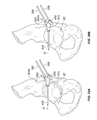
- FIGS. 8B and 8C Another embodiment of a reamer 500' according to the present teachings is illustrated in FIGS. 8B and 8C .
- the reamers 500 and 500' can be used interchangeably and similar elements will be referenced with the same numerals herein below.
- the reamer 500 (500') can include a trocar or other guiding pin 502 that is sized to fit and be received in the pilot hole 89 of the acetabulum 82 for stabilizing and guiding the reamer 500 (500') along the alignment axis A, i.e., at a predetermined location and orientation.
- This guided reaming arrangement enables the surgeon to recreate the preoperative planned position and orientation for reaming the acetabulum 82 and implanting the acetabular component.
- the alignment rod 402 which is supported by the support device 400 along the axis A' that is parallel to the alignment axis A can also help to guide the reamer 500 (500').
- the reamer 500 can include a plurality of curved reaming blades 504 and a supporting shaft 506 for a reamer driver or reamer handle.
- the curved blades 504 can be attached to a plurality of curved supporting elements 508 in the form of spherical leaves or spherical section/portions that collectively define a semi-spherical surface corresponding to the shape and size of the acetabular component to be implanted in the acetabulum after reaming.
- the blades 504 can be removable and replaceable or disposable.
- the entire reamer head that includes the blades 504 and the support element 508 can also be disposable.
- a reamer 500 with four disposable blades 504 is illustrated in FIG.
- the guiding pin 502 can be spring biased to provide a tactile feedback during reaming.
- a spring or other biasing element 510 can be constrained between a proximal end 512 of the guiding pin 502 and a wall 514 of the supporting shaft 506.
- a set screw or fastener 516 can be used to stabilize the guiding pin 502 while allowing slidable movement along the alignment axis during reaming.
- the spring 510 can surround the fastener 516, as shown in FIG. 8C .
- the fastener 516 is threaded to a blind bore 503 of the guiding pin 502 such that the fastener 516 and the guiding pin can move together along the alignment axis A by or against the action of the spring 510.
- the embodiments of FIGS. 8B and 8C also include a base ring 518 integrally attached to the shaft 506 providing additional stability.
- an acetabular inserter 550 can be coupled to an acetabular cup 280 by an end coupler 552 at the distal end of a shaft 554 of the acetabular inserter 550.
- the shaft 554 can be slidably and removably coupled or engaged to the engagement surface 434 of the connector 432 of the support device 400, such that the shaft is oriented and can slide along the alignment axis A for insertion of the acetabular cup 280 according to the preoperatively planned position and orientation.
- the acetabular inserter 550 can include an impact head 520 and can be used to impact the acetabular cup 280 after implantation.
- markers pins 260 are inserted through the corresponding bores 252 of the marker elements 250 and attached to the bone in locations and orientations parallel to an axis B, as determined during the preoperative plan.
- the marker pins 260 can guide the location of a secondary guide 600, shown in FIG. 13 , and designed according to the pre-operative plan to be guided by the marker pins 260, as discussed below.
- the acetabular guide 200 can be slidably lifted off the marker pins 260 and removed, leaving the marker pins 260 attached to the bone.
- the acetabular cup 280 can be inserted using an acetabular inserter 550 without the aid of an alignment orientation, although a support device 400 with an alignment rod 402 can also be used if desired.
- a reamer 500, 500' with a guiding pin 502 can be used to ream the acetabulum 82, as discussed above in connection with FIG. 7 , although other commercially available reamers can also be used.
- a pilot hole 89 of predetermined length is drilled into the acetabulum 82 through the guiding element 204 with a drill element 440 until the stop 442 of the drilling element reaches the upper surface of the guiding element 204 of the acetabular guide 200.
- a secondary guide 600 having secondary marker elements 650 with bores 652 complementarily corresponding to the orientation and relative location of the marker elements 250 of the acetabular guide 200 is placed over the marker pins 260.
- the secondary guide 600 can be designed during the pre-operative plan such that the bores 652 are complementary to the location and orientation of the marker elements 250 of the acetabular guide.
- the secondary guide 600 can include extender elements 604 supporting an arcuate or crescent-shaped planar flange 602 having parallel inferior and superior surfaces 608, 610 designed during the pre-operative plan to be oriented parallel to a rim 282 of the acetabular cup 280, when the acetabular cup 280 is positioned in the predetermined position and orientation.
- the orientation and position of the acetabular cup 280 is adjusted using the secondary guide 600, such that the planar flange 602 (and the inferior and superior surfaces 608, 610 of the planar flange 602) and the rim 282 are parallel by ascertaining contact and engagement of the planar flange 602 to the rim 282 of the acetabular cup 280 in situ.
- acetabular guides 200 can also be used with the supporting device, at the discretion of the surgeon.
- any selected or all the acetabular guides 100 (110A, 100B, 100C) and 200 (200A, 200B) and the associated instruments including the reamer 500, 500', the supporting device 400, the drilling element 440 with the stop 442, alignment rod 402, marker pins 260 and the secondary guide 600 can be provided in a surgical kit together with the acetabular cup 280 and/or additional implants and instruments.
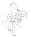
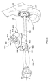
- FIG. 14 another embodiment of the support device 400 is support device 700 illustrated with a guiding handle 300' and an acetabular guide 100 for positioning an alignment rod 402 in the pre-planned orientation A'.
- the support device 700 can be attached to the bone with bone pins 703 that pass through arms 705.
- the arms 705 extend slidably from a body 707 and can include scale markings 709 for measuring distances from the body 707.
- the body 707 can include a planar slot 711 through which a first planar flange 713 can slidably pass there through and locked with a fastener (not shown) after adjustment.
- the first planar flange 713 includes arms 715 pivotably connected to a second planar flange 717 along a pivot axis coinciding with a center axis of a locking element 719.
- the locking element 719 can be used to lock the relative orientations of the first and second planar flanges 713, 717.
- the second planar flange 717 can have a curved engagement surface 721 for slidably engaging a shaft 304' of the guiding handle 300'.
- the shaft 404' can include a groove 303 that is rotationally keyed to an element 721 extending from the second planar flange 717.
- the support device 700 can provide pivotable and translational adjustability to align the alignment rod 402 parallel to the alignment axis A which is fixed when the shaft 304' is attached to the guiding element 104 of the acetabular guide.
- the support device 700 can be used generally similarly to the support device 400 to provide a reference axis A' along the reference or alignment rod 402 to guide a reamer 500 or implant inserter 550.
- the acetabular guide 200C includes a patient-specific body 202 and a guiding or pilot element 204 having an elongated bore 206 with an alignment axis A configured to be central to the acetabular cup and perpendicular to the acetabular cup's surface when the acetabular guide 200 is positioned on the acetabulum 82.
- the acetabular guide 200 can include one or more marker elements 250 (two are shown), each having an elongated bore 252 for guiding corresponding marker pins 260.
- the marker pins 260 can be used for supporting a secondary guide such as discussed below in reference to FIG. 12 above, or a secondary guide shown in FIG. 16 .
- the patient specific body 202 of acetabular guide 200C is similar to the body 202 of the acetabular guide 200A or 200B of FIGS. 4 and 5 , and includes a first portion 202a from which the guiding element extends and which is designed to engage the acetabulum 82, and a second portion 202b which extends from the inner portion 202a and is configured to extend over a rim portion 84 of the acetabulum 82.
- the outer portion 202b extends sufficiently beyond the rim 84 to the periacetabular area of pelvis to accommodate the marker elements 250.
- the patient specific body 202 has an underside or bone-engaging three-dimensional engagement surface 208 that is custom-made or patient-specific to conform to and mirror (as a negative or inverse or mirror surface) complementary surfaces of selected portions of the acetabulum 82.
- the patient specific body 202 includes additionally a third portion 202c which conforms to and covers at least a portion of the acetabular fossa 85 of the acetabulum for providing additional rotational stability.
- an inferior edge 203 of the acetabular guide 200C on the third portion 202c is designed during the preoperative plan to be parallel to the shape of the transverse acetabular ligament 83.
- the inferior edge 203 can provide an additional visual confirmation of correct alignment during positioning of the acetabular guide 200C on the acetabulum 82 of the patient.
- the secondary guide 600A can be used with any of the acetabular guides 200 (200A, 200B, 200C).
- the secondary guide 600A can have first and second (secondary) marker elements 650 with bores 652.
- the secondary guide 600 can be designed during the pre-operative plan such that the bores 652 are complementary to the location and orientation of the marker elements 250 of the acetabular guide.
- the marker pins 260 are secured into the bone through the marker elements 250 of the acetabular guide 200, as shown, for example, in FIG. 10 , and discussed above.
- the acetabular guide 200 is then lifted off the marker pins 260 and the secondary guide 600A is guided and placed over the marker pins 260.
- the secondary guide 600A is also designed during the preoperative plan for the patient to have a guiding element 670 with a longitudinal bore 672 along an axis A' that is parallel to the alignment axis A for the acetabular implant, when the secondary guide 600A is seated on the acetabulum over the marker pins 260, as shown in FIG. 16 . Accordingly, an alignment pin 402 inserted into the bore 672 can serve as an indicator of the alignment direction A for reaming the acetabulum and inserting the acetabular cup.
- the alignment axis A is the pre-operatively planned axis for insertion of the acetabular cup 280.
- the alignment axis A is shown, for simplicity, to coincide with the center axis of various instruments used for inserting, reaming and impacting the acetabular cup 280, it should be appreciated that this designation is adapted to indicate the final positioning of the instrument in the desired alignment. In other words, the alignment axis A and the axis of the instrument used are brought to coincidence by the methods described herein.
- the guiding element 670 may be placed in an offset position relative to the secondary marker elements 650 to provide better visualization of the acetabulum while guiding a reamer, inserter, impactor or other instrument along the alignment axis A parallel to the alignment pin 402.
- the acetabular inserter 550 coupled to the acetabular cup 280 can be guided along the alignment axis A by the alignment pin 402 of the secondary guide 600A (or the offset secondary guide 600B), as an alternate method that does not use the support device 400 described above and shown in FIG. 9 .
- an adaptor 680 shown in FIGS. 19-20B , can be optionally used to couple the acetabular inserter 550 to the alignment pin 402 of the secondary guide 600A, as a further aid to orient the acetabular inserter 550 along the alignment axis A.
- the adaptor 680 includes an arm 682, such as a cannulated shaft having a longitudinal bore 684 that receives the alignment pin 402 when the adaptor 680 is placed over the alignment pin 402. Accordingly, the shaft 682 is aligned along the axis A' that is defined by the guiding element 670 of the secondary guide 600A.
- the adaptor is coupled to a rotatable collar 560 of the acetabular inserter 550 and secures the acetabular inserter 550 along the alignment axis A parallel to the axis A' of the shaft 682 and alignment pin 402.
- the adaptor 680 can be coupled to the collar 560 with a tongue-in-groove or other keyed connection, as illustrated in FIGS. 20A and 20B .
- the collar 560 can include an extension 562 forming a keyhole-shaped opening 565 with a first portion 564 having a circular cross-section and a second portion 566 having an elongated cross-section.
- the keyhole opening 565 receives correspondingly shaped portions of the adaptor 680, forming a key 685 for the keyhole opening 565 and preventing rotational movement.
- the key 685 has a first cylindrical element 686 received in the first portion 564 of the opening 565 and a second element 688 extending at a right angle from the first element 686 and received into the second portion 566 of the keyhole opening 565.
- the key 685 and the keyhole opening 565 are angled at an acute angle relative to the alignment axis A and axis A'.
- the first portion 564 of the keyhole opening 565 and the first element 686 of the key 685 are oriented along the direction of an axis C forming an acute angle ⁇ with axes A and A' as shown in FIGS. 20A and 20B .
- This skewed orientation facilitates the insertion of the key 685 into the keyhole opening 565 and the coupling of the adaptor 680 to the acetabular inserter 550.
- the arm of 682 of the adaptor 680A can include an external V-shaped notch 690 instead of an internal cannulation 684 of the embodiment 680 of FIGS. 20A and 20B , while retaining the key 685 for engagement with the keyhole opening 565 of the acetabular inserter 550.
- the notch 690 can receive the alignment pin 402 in a semi-constrained arrangement for facilitating engagement and disengagement between the adaptor 680A and the alignment pin 402.
- FIGS. 22-29 various methods for preparing the acetabulum for receiving an implant will be discussed in connection with the use of electronic positioners (800, 900) or other orientation devices for guiding the surgeon along the alignment axis A during reaming and/or inserting and impacting the acetabular implant into the acetabulum.
- Any commercially available orientation sensing devices can be used for the electronic positioner 800 ( FIG. 22 ) or electronic positioner 900 ( FIGS. 28 and 29 ).
- Various embodiments of the electronic positioner 900 are described in commonly assigned patent publications 2010/0249657 , and 2010/0249796, both published on September 30, 2010 .
- the electronic positioners can include a number of gyroscopic sensors and/or accelerometers that can measure deviations from a predetermined orientation and maintain or guide a return to that orientation.
- the predetermined orientation is the alignment axis A that was discussed above.
- digital or MEMS gyroscopes of small size and capable of measuring deviation about two or three sin axes can be used, such as, for example, a three-axis, single sensor digital gyroscope (model L3G4200D) available from STMicroelectronics, Carrollton, Texas.
- any combination of orientation sensors capable of identifying an orientation in three-dimensional space including combinations of gyroscopic sensors (digital, analog, fiber optic or other type), having one or more axes, with other orientation sensors, such as accelerometers, such that the combination can identify deviations from an axis in three-dimensional space.
- a 3-axis gyroscope yaw, roll and pitch
- three one-axis gyroscopes or one 2-axis gyroscope and one accelerometers
- the accelerometers can be single or multiple axes accelerometers. Mechanical, piezoelectric, MEMS, analog or digital accelerometers and gyroscope can be used.
- a miniaturized compass, a laser, and/or GPS device may be included with the electronic positioner.
- the electronic positioner 800 can include a housing 802 that is removably attachable to a shaft of an inserter, impactor, reamer or other instrument used in connection with the acetabular arthroplasty or other corrective procedure.
- the electronic positioner is shown coupled to the acetabular inserter 550.
- the electronic positioner 800 can be, for example, keyed to the shaft 554, slidably attached to the shaft 554 or the collar 560 of the acetabular inserter 800 or slip-fit or with a clamp-on or tongue-and-groove or other coupling arrangement.
- the housing 802 can include a controller/processor communicably coupled to the orientation sensor/sensors discussed above, and a feedback module.
- An exemplary block diagram for the electronic positioner 900 of FIG. 20 is shown in FIG. 29 , described below, and can be used for the electronic positioner 800, although the impact sensor and associated modules are optional and can be omitted from the electronic positioner of 800.
- the electronic positioner 800 can include a power or on/off button 806, a set button/input device 808 for setting a pre-determined orientation during calibration and a set of LEDs 804 (outer set 804) for guiding the shaft 554 along the predetermined orientation (i.e., the alignment axis A) by lighting up to indicate a direction.
- the electronic positioner 800 can also include an optional laser device 810 capable of providing a reference orientation 812.
- the laser device 810 may be used, for example, with accelerometers that measure in two non parallel directions in a plane perpendicular to the reference orientation 812 of the laser.
- the electronic positioner 800 can be calibrated using one of the patient-specific acetabular guides described above, such as, for example, the acetabular guide 200C, shown in FIG. 22 .
- the acetabular guide 200C can be positioned at a unique position on the patient's acetabulum, such that the guiding element 204 defines the alignment axis A, as designed during the preoperative plan.
- the shaft 554 of the acetabular inserter 550 can be slidably coupled to the guiding element 204 as described above in reference to FIG. 6 , for example, such that the longitudinal axis of the shaft 554 coincides with the alignment axis A.
- the set button/input device 808 can be pressed or otherwise activated to set or identify the alignment axis A as a reference axis, and store its orientation.
- deviations from the reference axis can be calculated by the sensors (see 934, FIG. 29 ) of the electronic positioner, processed by the controller (see 946, FIG. 29 ) of the electronic positioner and feedback provided by the LEDs 804 indicating the direction and increment of deviation.
- the direction of deviation or, alternatively the direction to move to correct the deviation can be indicated by the direction defined by a lit LED, such as, for example, 804b relative to a central LED 804a, which lights up when the shaft 554 is correctly aligned along the reference/alignment axis A.
- a relative amount or degree of deviation for a given direction of a deviation can be indicated by a change in color of the LEDs 804, or by another set of LEDs 803 (inner set) that light up at a different fixed color, for example a fixed yellow to a fixed red of the outer set of LEDS 804.
- FIGS. 23A and 23B illustrate the patient's acetabulum 82 before and after reaming, respectively.
- the acetabular inserter 500 with the electronic positioner 800 thereon can be coupled to the acetabular implant 280, as shown in FIG. 24 , for inserting the acetabular implant 280 along the predetermined alignment axis A, as guided by the electronic positioner 800.
- Feedback from the LEDs 804 and/or 803 or other feedback mechanism can help guide the surgeon to correct any deviation from the predetermined alignment axis A that coincides with the calibrated reference axis of the electronic positioner 800, as discussed above.
- marker pins 260 and a secondary guide 600, 600A, 600B are not necessary.
- the marker pins 260 and the secondary guide 600A can be used together with the electronic positioner 800, as illustrated in FIGS. 25-27 .
- the marker pins 260 can be inserted, for example, through the marker elements 250 of the patient-specific acetabular guide 200C, as shown in FIG. 25 during calibration of the electronic positioner 800.
- the patient-specific acetabular guide 200C is lifted off the marker pins 260, which are left attached to the acetabulum 82 for guiding the placement of the secondary guide 600A (or 600B or 600), as shown in FIG. 26A .
- the alignment pin 402 can be used as a reference for the implant alignment axis A. In some embodiments, the alignment pin 402 can be used to align a supporting shaft 506 of a reamer 500 (see FIG. 8A ) parallel to the direction A' of the alignment pin 402 and used during reaming. After reaming, the secondary guide 600A and the marker pins 260 can remain attached to the acetabulum, as shown in FIG.
- the alignment pin 402 of the secondary guide 600A can provide an initial reference direction A' for the surgeon to position the acetabular inserter 800 easier and quicker along the alignment direction A, and make smaller corrections in orientation with the help of the LEDs 804, 803 or other feedback mechanism of the electronic positioner 800.
- the electronic positioner 900 of the above referenced patent publications 2010/0249657 and 2010/0249796 is briefly described. It will be appreciated that in some embodiments, the electronic positioner 900 can replace the electronic positioner 800 in the methods described above. In other embodiments, the electronic positioner 800 can incorporate all or some of the functions of the electronic positioner 900, while maintaining, for example, the geometry of the housing 802 and the LED feedback arrangement described above in reference to FIG. 22 . In some embodiments, the electronic positioner 800 can include a orientation sensor (or sensors) 934, but not impact sensors 947 and impact feedback, as discussed below. In other embodiments, the electronic positioner 800 may also include the impact sensor 947 and associated feedback mechanisms of the electronic positioner 900.
- the electronic positioner 900 can include a cylindrical housing 926 coupled to an acetabular inserter/impactor tool 916 having a longitudinal shaft 918.
- the housing 926 can include a passage 930 that receives the shaft 918 and couples the housing 926 to the acetabular inserter/impactor tool 916 in a fixed position relative to the shaft 918.
- the housing 926 can include a seam or hinge or other longitudinal separator 931 between first and seconds portions 932a, 932b of the housing 926 for removing the housing 926 from the shaft 918.
- the hinge 931 can operate to secure the first and second portions 932a, 932b in a clam shell design of the housing 926.
- the housing 926 can be attached to the shaft 918 in any suitable fashion, such as an interference fit, a taper to taper fit between the shaft 918 and the inner surface of the passage 930, or other arrangement.
- the shaft 918 can include a recess (not shown) that receives the housing 926 such that the housing 926 is in a fixed position relative to the shaft 918.
- the electronic positioner 900 can be removably coupled to various commercially available inserter/impactor tools 916, such as a RingLoc ® Inserter (Part No. S313141) or a Magnum Inserter (Part No. 313131), commercially available from Biomet Manufacturing Corp., of Warsaw, Indiana.
- the electronic positioner 900 can be similarly coupled to the shaft of the inserter 550 or reamer 500 or guiding handle 300 or other tool used during the acetabular procedure for guiding along the alignment axis A.
- the electronic positioner 900 can include one or more orientation sensors 934.
- the orientation sensor 934 can detect an actual orientation of the longitudinal axis of the inserter/impactor tool 916 relative to a reference orientation or reference vector, such as the force of gravity.
- the orientation sensor 934 can detect acceleration about three separate orthogonal axes (accelerometer sensors) or angular velocity (spin) about one or more orthogonal axes (gyroscopic sensor), as discussed above in reference to the electronic positioner 800.
- the electronic positioner 900 (or 800) can include an orientation feedback device 936.
- the orientation feedback device 936 can selectively provide an orientation feedback signal when the actual orientation of the inserter/impactor tool 916 is substantially equal to a predetermined target orientation, i.e., the alignment axis A discussed above.
- the feedback signal provided by the orientation feedback device 936 can automatically indicate to the surgeon that the inserter/impactor tool 916 is in the target orientation, such that the acetabular cup can be properly positioned and implanted for added convenience and accuracy.
- the orientation feedback device 936 can include an audible feedback device 938 that emits an audible feedback signal.
- the audible feedback device 938 can include a speaker that emits a preprogrammed sound when the inserter/impactor tool 916 is in the target orientation.
- the orientation feedback device 936 can include a visual feedback device 940 that emits a visual feedback signal.
- the visual feedback device 940 can include one or more lights, such as LED lights, for emitting a preprogrammed light pattern when the inserter/impactor tool 916 is in the target orientation. An embodiment of the visual feedback device 940 is described above in connection with the LEDs 804 and 803 of the electronic positioner 800.
- the orientation feedback device 936 can include a tactile feedback device that selectively emits a tactile feedback signal when the inserter/impactor tool 916 is in the target orientation.
- the tactile feedback device 942 can include a vibration motor that selectively vibrates the housing 926 and the inserter/impactor tool 916 when the inserter/impactor tool 916 is in the target orientation.
- orientation feedback device 936 can provide any suitable feedback signal, including combinations of visual, audible and tactile feedback. Also, it will be appreciated that the feedback signal can be seen, heard, and felt simultaneously, and this redundancy can increase accuracy and convenience.
- the electronic positioner 900 (or 800) can include a controller 946.
- the controller 946 can include various components, such as a microprocessor, memory, and the like.
- the controller 946 can be in communication with the orientation sensor 934 and the orientation feedback device 936. Accordingly, the controller 946 can cause the orientation feedback device 936 to selectively provide the respective orientation feedback signal(s) when the actual orientation of the inserter/impactor tool 916 detected by the orientation sensor 934 is substantially equal to a predetermined target orientation of the inserter/impactor tool 916.
- the electronic positioner 900 can include an impact sensor 947 to help the surgeon determine more accurately and conveniently when the acetabular cup 280 is fully seated in the acetabulum 82 of the patient.
- the impact sensor 947 can detect an actual impact effect on the inserter/impactor tool 916.
- the impact sensor 947 can be configured to detect an actual impact force F i on the head 920 of the inserter/impactor tool 916.
- the impact sensor 947 can also detect an actual displacement of the inserter/impactor tool 916 when the load F i is applied to the head 920.
- the impact sensor 947 can detect an actual acoustic effect of the impact when the load F i is applied.
- the impact sensor 947 can be configured to detect any suitable effect of applying the load F i .
- the impact sensor 947 can include any suitable component, such as an accelerometer and/or a piezoelectric sensor, for detecting the actual impact effect.
- the orientation sensor 934 and the impact sensor 947 can rely, at least in part, on some of the same components, such as a common accelerometer, for the respective functions.
- the electronic positioner 900 can include an impact feedback device 948.
- the impact feedback device 948 can provide a feedback signal when the actual effect of applying the load F i detected by the impact sensor 947 substantially matches a predetermined target impact effect. More specifically, the surgeon can predetermine a target impact effect (e.g., a predetermined impact force F i , an amount of displacement, an acoustic effect, etc.) that correlates to a condition in which the acetabular cup 280 is fully seated in the acetabulum 82 of the patient. Then, the controller 946 can cause the impact feedback device 948 to provide the respective feedback signal when the actual impact effect substantially matches the predetermined target impact effect. Thus, the impact feedback device 948 can inform the surgeon that the acetabular cup 280 has been fully seated into the acetabulum 82 of the patient.
- a target impact effect e.g., a predetermined impact force F i , an amount of displacement, an acoustic effect, etc.
- the impact feedback device 948 can include any suitable device, such as an audible feedback device 950, a visual feedback device 952, and/or a tactile feedback device 954.
- the audible feedback device 950 can provide an audible feedback signal, and can include a speaker or any other suitable device for providing an audible feedback signal.
- the visual feedback device 952 can provide a visual feedback signal, and can include one or more lights, such as LED lights, for providing a visual feedback signal.
- the tactile feedback device 954 can provide a tactile feedback signal and can include a vibration motor that selectively provides a tactile feedback signal.
- the electronic positioner 900 can include an input device 941 for manually setting the target orientation of the inserter/impactor tool 916. More specifically, the input device 941 can include buttons, dials, a display, and other features for setting a target inclination angle, a target anteversion angle, or any other setting for the orientation of the alignment axis A.
- the input device 41 can be integrally coupled to the housing 926, and/or the input device 941 can be separate and remote from the housing 926.
- the input device 941 can include a wireless transmitter 943, and the housing 926 can include a wireless receiver 945.
- the receiver 945 receives wireless signals from the transmitter 943 to thereby set the target orientation of the alignment axis A.
- the input device 941 can include an alphanumeric keypad for manually inputting and setting a particular target orientation. Additional details about of the electronic positioner 900 can be found in patent publications 2010/0249657 and 2010/0249796 , referenced above.
- Various patient-specific guides, secondary guides, reamers, guide handles, inserters, impactors, support devices, electronic positioners and other instruments can be used in various combinations and based on surgeon preferences or patient and preoperative or intraoperative circumstances for preparing an acetabulum and guiding and implanting an acetabular implant along a preoperatively determined alignment orientation.
- tools and instrumentation providing redundant functionality and of different embodiments may provided to the surgeon in a kit or per surgeon's request.
- more than one patient specific acetabular guide (100, 200) may be provided.
Landscapes
- Health & Medical Sciences (AREA)
- Life Sciences & Earth Sciences (AREA)
- Orthopedic Medicine & Surgery (AREA)
- Surgery (AREA)
- Oral & Maxillofacial Surgery (AREA)
- Engineering & Computer Science (AREA)
- Biomedical Technology (AREA)
- Heart & Thoracic Surgery (AREA)
- Animal Behavior & Ethology (AREA)
- General Health & Medical Sciences (AREA)
- Public Health (AREA)
- Veterinary Medicine (AREA)
- Medical Informatics (AREA)
- Molecular Biology (AREA)
- Transplantation (AREA)
- Dentistry (AREA)
- Nuclear Medicine, Radiotherapy & Molecular Imaging (AREA)
- Vascular Medicine (AREA)
- Physical Education & Sports Medicine (AREA)
- Cardiology (AREA)
- Prostheses (AREA)
- Surgical Instruments (AREA)
Description
- The present teachings provide a patient-specific acetabular guide and related instruments for preparing an acetabulum to receive an acetabular implant and guiding the implant into the acetabulum of a patient.
- Document
US2011184419 A1 discloses an acetabular guide combination according to the preamble of claim 1. The present teachings provide various instruments for generally preparing the acetabulum of a patient to receive an acetabular implant, such as, for example, an acetabular cup along an alignment axis. The alignment axis and various patient-specific guides and instruments can be designed during a pre-operative plan using a three-dimensional reconstruction of the patient's relevant anatomy, such as the pelvis or portions thereof, including the acetabular and periacetabular areas of the pelvis. The three-dimensional reconstruction can be based on two-dimensional medical images, including MRI, CT or X-ray scans and prepared using commercially available imaging software. - The present teachings provide, for example, an acetabular guide that includes a patient-specific engagement surface designed to be complementary and mateable with a corresponding surface of the patient's pelvic anatomy. The acetabular guide is designed during the pre-operative plan for the patient using the three-dimensional reconstruction of the anatomy of the patient. The patient-specific engagement surface has a first portion mateable with a portion of the acetabulum of the patient. The acetabular guide includes a guiding element that extends from the acetabular guide opposite to the first portion of engagement surface. The guiding element defines a bore designed to be oriented along an alignment axis for an acetabular implant when the acetabular guide is engaged to the acetabulum. A drilling element with a stop can be used to drill a pilot hole into the acetabulum along the alignment axis.
- The acetabular guide can be provided in various fitment options in which the patient-specific engagement surface is designed to fit in a unique position relative to the patient anatomy. Each fitment option of the acetabular guide includes a portion that covers a center of the acetabulum for aligning the acetabular implant and additional portions complementary to a portion of the acetabular rim and/or a portion of the transverse acetabular ligament. Each fitment option allows the acetabular guide to have a compact size, extend through the center of the acetabulum for alignment, and include portions that can fit over various anatomic landmarks in a unique position for the patient. The particular fitment option can be selected for each specific patient based on the patient's anatomy, the procedure to be performed and the surgeon's preference and/or technique.
- The acetabular guide includes first and second marker elements extending from a portion of the acetabular guide outside the acetabulum of the patient. The marker elements define corresponding first and second bores for guiding first and second marker pins into a bone portion of the patient. A secondary guide is used with the marker pins to orient an acetabular cup into a predetermined position and orientation. The secondary guide is designed during the pre-operative plan to include first and second guiding elements complementary to the first and second marker elements of the acetabular guide for receiving the first and second marker pins when the first and second marker pins are attached to the bone portion of the patient.
- The acetabular guide can be used according to the present teachings with a guiding handle support device that can be attached to the pelvis and provides an alignment rod as a reference for the alignment axis. The guiding handle can be removably attached to the guiding element of the acetabular guide along the alignment axis. The support device can include a connector supporting the alignment rod. The connector can be removably engaged with a shaft of the guiding handle. The support device includes rotational and translational mechanisms for orienting the alignment rod parallel to the shaft of the guiding handle and parallel to the alignment axis such that the alignment rod can provide a reference axis for the alignment axis.
- The present teachings also provide a reamer having a guiding pin. The guiding pin of the reamer can be received in the pilot hole that is drilled in the acetabulum through the bore of the guiding element of the acetabular guide. The guiding pin is thus oriented along the alignment axis. In some embodiments, the reamer includes a spring that biases the guiding pin and provides tactile feedback during reaming. In some embodiments, the reamer includes a plurality of removable arcuate blades. The blades can be disposable or replaceable. In some embodiments, each blade is attached to a corresponding supporting element shaped as a spherical section, such that the supporting elements collectively form a surface corresponding to a shape of the acetabular cup.
- The various instruments described above can be used in various combinations reaming the acetabulum and inserting an acetabular implant according to a pre-operative plan. Also described herein are methods for reaming and preparing an acetabulum of a patient for an acetabular implant. One method includes engaging an acetabular area of the patient with a complementary surface of a patient-specific acetabular guide, supporting an alignment rod on a support device attached to the patient's pelvis and orienting the alignment rod to be parallel to an alignment axis for inserting the implant. The alignment axis is determined during a preoperative plan of the patient and coinciding with a center axis of a guiding element of the acetabular guide. The method further includes drilling a pilot hole in the acetabulum through a bore of the guiding element along the center axis, removing the acetabular guide, guiding an alignment pin of a reamer in the pilot hole such that the alignment pin is parallel to the alignment rod, and reaming the acetabulum.
- Another method includes engaging an acetabular area of the patient with a complementary surface of a patient-specific acetabular guide. The acetabular guide is designed during a pre-operative plan from a reconstructed three-dimensional image of the patient's anatomy. The method includes drilling a pilot hole in the acetabulum through a bore of a guiding element of the acetabular guide along a patient-specific alignment axis determined by the guiding bore. The method also includes inserting first and second marker pins into an area outside the acetabulum of the patient through corresponding first and second marker elements of the acetabular guide. The method includes removing the acetabular guide without removing the marker pins, reaming the acetabulum, inserting an acetabular cup in the reamed acetabulum and sliding a secondary guide over the first and second marker pins. The method further includes engaging a planar arcuate surface of the secondary guide to a complementary rim surface of the acetabular cup to align the acetabular cup to a position and orientation determined in the pre-operative plan.
- Another method includes using an electronic positioner for guiding an acetabular inserter into the acetabulum along a predetermined patient-specific alignment axis. The electronic positioner is capable of indicating a predetermined orientation using one or more orientation sensors. A patient-specific acetabular guide is placed on the acetabulum of the patient in a unique mated position. The acetabular guide has a guiding element oriented along the patient-specific alignment axis. A shaft of the acetabular inserter is inserted into the guiding element of the acetabular guide, such that the shaft of the acetabular inserter is oriented along the alignment axis. The electronic positioner is removably attached to the shaft of the acetabular inserter and is calibrated to indicate the alignment axis. After the acetabular guide is removed and the acetabulum prepared, the acetabular inserter with the acetabular implant can be guided along the alignment axis using feedback from the electronic positioner.
- Further areas of applicability of the present teachings will become apparent from the description provided hereinafter. It should be understood that the description and specific examples are intended for purposes of illustration only and are not intended to limit the scope of the present teachings.
- Only the acetabular guide 200 (200A, 200B, 200C) and the
secondary guides secondary guide 600 do not fall within the scope of the claims. 30 - The present teachings will become more fully understood from the detailed description and the accompanying drawings, wherein:
-
FIGS. 1-5 illustrate environmental perspective views of various patient-specific acetabular alignment guides according to the present teachings; -
FIG. 6 is an environmental perspective view of various instruments illustrating a method for establishing an acetabular cup insertion axis according to the present teachings; -
FIG. 7 is an environmental perspective view illustrating drilling a pilot hole for guided reaming according to the present teachings; -
FIG. 8A is an environmental perspective view illustrating a reamer for guided reaming according to the present teachings; -
FIG. 8B is a stylized perspective view of a reamer for guided reaming according to the present teachings; -
FIG. 8C is a partially sectioned perspective view of the reamer ofFIG. 8B ; -
FIG. 9 is an environmental perspective view illustrating instruments for cup insertion according to the present teachings; -
FIG. 10 is an environmental perspective view of a patient-specific acetabular alignment guide with alignment pins for a secondary guide according to the present teachings; -
FIG. 11 is an environmental perspective view of another patient-specific acetabular alignment guide with alignment pins for a secondary guide according to the present teachings; -
FIG. 12 is an environmental perspective view of the patient-specific acetabular alignment guide ofFIG. 10 illustrating drilling a pilot hole for guided reaming according to the present teachings; -
FIG. 13 is an environmental perspective view of a secondary guide over the alignment pins ofFIG. 10 according to the present teachings; -
FIG. 14 is an environmental perspective view of a patient-specific acetabular alignment guide with an alignment pin and supporting instruments according to the present teachings; -
FIG. 15 is an environmental view of another embodiment of a patient-specific acetabular alignment guide shown with marker pins according to the present teachings; -
FIG. 16 is an environmental view of another embodiment of a secondary guide shown with marker pins according to the present teachings; -
FIG. 17 is an environmental view of another embodiment of a secondary guide shown with marker pins according to the present teachings; -
FIG. 18 is an environmental view illustrating a method of inserting an acetabular cup using the secondary guide ofFIG. 16 ; -
FIG. 19 is an environmental view illustrating another method of inserting an acetabular cup using an acetabular inserter coupled to the secondary guide ofFIG. 16 with an adaptor according to the present teachings; -
FIGS. 20A and 20B are perspective views of a detail of coupling between the acetabular inserter and the adaptor ofFIG. 19 ; -
FIG. 21 is a perspective view of another embodiment of an adaptor for coupling an acetabular inserter to a secondary guide according to the present teachings; -
FIG. 22 is an environmental perspective view illustrating calibrating an electronic positioner coupled to an acetabular inserter and using a patient-specific alignment guide without marker pins according to the present teachings; -
FIGS. 23A and 23B illustrate an acetabulum before and after reaming, respectively; -
FIG. 24 is an environmental perspective view illustrating inserting an acetabular cup using the calibrated positioner ofFIG. 22 according to the present teachings; -
FIG. 25 is an environmental perspective view illustrating calibrating an electronic positioner coupled to an acetabular inserter and using a patient-specific alignment guide with marker pins according to the present teachings; -
FIGS. 26A and 26B illustrate an acetabulum before and after reaming, respectively, using a secondary guide for alignment during reaming according to the present teachings; -
FIG. 27 is an environmental perspective view illustrating inserting an acetabular cup using the calibrated positioner and secondary guide ofFIG. 25 according to the present teachings; -
FIG. 28 is a perspective view of an electronic positioner coupled to an acetabular inserter/impactor as disclosed in commonly assignedU.S. Patent Publication 2010/0249796 ; and -
FIG. 29 is a schematic view of the electronic positioner ofFIG. 28 . - The following description is merely exemplary in nature and is in no way intended to limit the present teachings, applications, or uses.
- The present teachings generally provide various patient-specific acetabular alignment guides, secondary guides, reamers, inserters, impactors and other associated instruments for use in orthopedic surgery, such as in joint replacement or revision surgery, for example. The patient-specific alignment guides and associated instruments can be used either with conventional or with patient-specific implant components prepared with computer-assisted image methods.
- As described in commonly assigned
U.S. Application No. 11/756,057, filed on May 31, 2007 - Computer modeling for obtaining three-dimensional computer images of the relevant patient's anatomy can be provided by various CAD programs and/or software available from various vendors or developers, such as, for example, from Materialise USA, Plymouth, Michigan. The computer modeling program can be configured and used to plan a preoperative surgical plan, including planning various bone preparation procedures, to select or design/modify implants and design patient-specific guides and tools including patient-specific prosthesis components, and patient-specific tools, including reaming, broaching, milling, drilling or cutting tools, alignment guides, templates and other patient-specific instruments.
- The pre-operative plan can be stored in any computer storage medium, in a computer file form or any other computer or digital representation. The pre-operative plan, in a digital form associated with interactive software, can be made available via a hard medium, a web-based or mobile or cloud service, or a cellular portable device to the surgeon or other medical practitioner, for review. Using the interactive software, the surgeon can review the plan, and manipulate the position of images of various implant components relative to an image of the anatomy. The surgeon can modify the plan and send it to the manufacturer with recommendations or changes. The interactive review process can be repeated until a final, approved plan, is sent to a manufacturing facility for preparing the actual physical components.
- After the surgical plan is approved by the surgeon, patient-specific implants and associated tools, including, for example, alignment guides, cutting/milling/reaming/broaching or other tools for the surgical preparation of the joint or other anatomy portion of the specific patient can be designed using a CAD program or other three-dimensional modeling software, such as the software provided by Materialise, for example, according to the preoperative surgical plan. Patient-specific guides and other instruments can be manufactured by various stereolithography methods, selective laser sintering, fused deposition modeling or other rapid prototyping methods. In some embodiments, computer instructions of tool paths for machining the patient-specific guides and/or implants can be generated and stored in a tool path data file. The tool path data can be provided as input to a CNC mill or other automated machining system, and the tools and implants can be machined from polymer, ceramic, metal or other suitable material depending on the use, and sterilized. The sterilized tools and implants can be shipped to the surgeon or medical facility for use during the surgical procedure.
- Patient-specific implants, guides, templates, tools or portions thereof are defined herein as those constructed by a surgical plan approved by the surgeon using three-dimensional images of the specific patient's anatomy and made to closely conform and mate substantially as a negative mold or negative surface or inverse or mirror surface of corresponding surface portions of the patient's anatomy, including bone surfaces with or without associated soft tissue, such as articular cartilage, for example, depending on the particular procedure, implant and tool use.
- Patient-specific alignment guides and implants are generally configured to match the anatomy of a specific patient and can fit in only one position on a corresponding surface of the specific patient because anatomic features that are unique to each patient function as landmarks and can guide placement of the alignment guide or implant in only one position without the need of intraoperative navigation, patient marking or other intraoperative guidance.. The patient-specific alignment guides are generally configured and manufactured using computer modeling based on the patient's 3-D anatomic image and have an engagement surface that is made to conformingly contact and match as a mirror or negative or inverse surface to a corresponding surface of a three-dimensional image/model of the patient's bone surface (with or without cartilage or other soft tissue), by the computer methods discussed above. The patient-specific alignment guides can include custom-made guiding formations, such as, for example, guiding bores or cannulated guiding posts or cannulated guiding extensions or receptacles that can be used for supporting or guiding other instruments, such as drill guides, reamers, cutters, cutting guides and cutting blocks or for inserting pins or other fasteners according to a surgeon-approved pre-operative plan. The patient-specific alignment guides can be used in minimally invasive surgery, and also in surgery with multiple minimally-invasive incisions. Various alignment guides and pre-operative planning procedures are disclosed in commonly assigned and co-pending
U.S. Patent Application No. 11/756057, filed on May 31, 2007 U.S. Patent Application No. 12/211407, filed September 16, 2008 U.S. Patent Application No. 11/971390 , filed on January 9, 2008,U.S. Patent Application No. 11/363548, filed on February 27, 2006 U.S. Patent Application No 12/025414, filed February 4, 2008 . The disclosures of the above applications are incorporated herein by reference. - Referring to
FIGS. 1-5 , the present teachings provide various patient-specific acetabular guides 100, 200. The acetabular guides 100, 200 can be used in connection with various other instruments to facilitate guided reaming of anacetabulum 82 of apelvis 80 of a specific patient and guided insertion and implantation of an acetabular implant or acetabular cup in theacetabulum 82. Further, the patient-specific acetabular guides 100, 200 engage theacetabulum 82 of the specific patient in a unique (only one) position and can provide an accurate alignment axis relative to the planned orientation of the acetabular cup 280 (shown inFIG. 9 , for example). The patient-specific acetabular guides 100, 200 can also provide secure fitting and rotational stability in a design that is lightweight with minimal size and bulk. -
FIGS. 1-3 illustrate a patient-specific acetabular guide 100 having a patient-specific body 102, as described below, and a guiding orpilot element 104 having anelongated bore 106 with a patient-specific alignment axis A for drilling a pilot hole on the acetabulum and/or establishing the alignment axis A for a reamer, implant inserter, impactor or other instruments used in the preparation and implantation procedure. The alignment axis A is configured to be central to the acetabular cup and perpendicular to the acetabular cup's surface when theacetabular guide 100 is positioned on theacetabulum 82. The alignment axis A helps orient and guide the acetabular implant and various related instruments along a patient-specific orientation established during the pre-operative plan for the patient. Theacetabular guide 100 can be provided in various fitment options depending on the planned exposure of theacetabulum 82 for the reaming procedure and implantation. Each fitment option of the acetabular guide can generally include a portion that covers a center of the acetabulum for aligning the acetabular implant and additional portions complementary to a portion of the acetabular rim and/or a portion of the transverse acetabular ligament. Each fitment option allows theacetabular guide 100 to have a compact size, extend through the center of theacetabulum 82 for alignment, and include portions that can fit over various anatomic landmarks in a unique position for the patient. The particular fitment option can be selected for each specific patient based on the patient's anatomy, the procedure to be performed and the surgeon's preference and/or technique. - Three exemplary fitment options designated 100A, 100B and 100C are illustrated in
FIGS. 1-3 , respectively. The fitment options can include fitments engaging or registering to various combinations of portions of the acetabulum 82, theacetabular rim 84 and thetransverse acetabular ligament 83. For example, theacetabular guide 100 in thefitment option 100A may engage a portion of the acetabulum 82, a portion of theacetabular rim 84 and a portion of thetransverse acetabular ligament 83. In thefitment option 100B, theacetabular guide 100 may engage a portion of theacetabulum 82 and a portion of theacetabular rim 84. In thefitment option 100C, theacetabular guide 100 may engage a portion of theacetabulum 82 and a portion of thetransverse acetabular ligament 83. Further details are discussed below. Either one or several acetabular guides 100A, 100B, 100C corresponding to different fitment options can be provided to the surgeon for intra-operative flexibility and plan change, according to the surgeon's preference. Theacetabular guide 100 can be secured to the patient's bone with bone pins, guide wires or other fasteners. - The patient-
specific body 102 of theacetabular guide 100 can include aninner portion 102a (all fitment options) from which the guiding element extends and which is designed to engage theacetabulum 82, anouter portion 102b which extends from theinner portion 102a and is configured to extend over a portion of the rim 84 (forfitment options outer portion 102c (fitment options specific body 102 has an underside three-dimensional engagement surface 108 that is custom-made or patient-specific to conform to and mirror (as a negative or inverse or mirror surface) complementary surfaces of various combinations of the acetabulum 82,rim 84 and/ortransverse acetabular ligament 83 or other periacetabular surfaces of thepelvis 80 of the specific patient, as described above in connection with the various fitment options. The patientspecific body 102 is designed by using a three-dimensional image or model of theacetabulum 82 and surrounding pelvic area of the patient, as described above. Theengagement surface 108 enables theacetabular guide 100 to nest or closely mate relative to the complementarily acetabular surface of the patient. Theacetabular guide 100 can be designed to have generally small thickness, such that it can form a lightweight three-dimensional shell from which the guidingelement 104 extends opposite to the engagement surface. The guidingelement 104 can be formed to be a monolithic or integral portion of theacetabular guide 100. Alternatively, the guidingelement 104 can be modularly and removably coupled to theacetabular guide 100, using, for example, a threaded connection, snap-on connectors or other removable attachments. - Referring to
FIGS. 4 and 5 , another patient-specific acetabular guide 200 is illustrated with exemplary twofitment options acetabular guide 100, theacetabular guide 200 also includes a patient-specific body 202 and a guiding orpilot element 204 having anelongated bore 206 with an alignment axis A configured to be central to the acetabular cup and perpendicular to the acetabular cup's surface when theacetabular guide 200 is positioned on theacetabulum 82. Theacetabular guide 200 can include one or more marker elements 250 (two are shown in the exemplary embodiments ofFIGS. 4 and 5 ), each having anelongated bore 252 for guiding marker pins 260. The marker pins 260 can be used for supporting a secondary guide for another preparation method discussed below in reference toFIG. 12 . The other features of theacetabular guide 200 are similar to that of theacetabular guide 100, such that theacetabular guide 200 can also be used instead of theacetabular guide 100. Theacetabular guide 100 can be used for procedures in which themarker elements 250 are not utilized, as described below. Theacetabular guide 200 can be used for procedures in which themarker elements 250 may or may not be utilized, as described below. - The patient-
specific body 202 of theacetabular guide 200 is generally similar to patient-specific body 102 of theacetabular guide 100, such that the patient-specific body 202 can include aninner portion 202a from which the guiding element extends and which is designed to engage theacetabulum 82, and anouter portion 202b which extends from theinner portion 202a and is configured to extend over arim portion 84 of theacetabulum 82. Theouter portion 202b extends sufficiently beyond therim 84 to the periacetabular area of pelvis to accommodate themarker elements 250. The patientspecific body 202 has an underside or bone-engaging three-dimensional engagement surface 208 that is custom-made or patient-specific to conform and mirror (as an inverse or negative or mirror surface) complementary surfaces of selected portions of the acetabulum 82, therim 84 and the transverse acetabular ligament 83 (depending on the fitment option) or other periacetabular surfaces of thepelvis 80 of the specific patient by using a three-dimensional image or model of the acetabulum and surrounding pelvic area of the patient, as described above. Theengagement surface 208 enables theacetabular guide 100 to nest or closely mate relative to the complementarily acetabular surface of the patient. Theacetabular guide 200 can be designed to have generally small thickness, such that it can form a lightweight three-dimensional shell from which the guidingelement 204 andmarker elements 250 extend. - Referring to
FIGS. 6-9 , a method for reaming and preparing the acetabulum for an implant is described in connection with the patient-specific acetabular guides 100. The acetabular guides 200 can also be used, although themarker elements 250 are not utilized in this method. Referring toFIG. 6 , a patient-specific acetabular guide 100 (or 200) is placed in a unique position on the acetabulum/rim/transverse acetabular ligament depending on the fitment option and associated anatomic landmarks of the patient, as determined in the preoperative plan for the specific patient. Once positioned, the guidingelement 104 establishes the alignment axis A for the specific patient. An elongated guiding handle 300 can be attached to the guidingelement 104 such that the center axis of the guidinghandle 300 coincides with the alignment axis A. The guiding handle 300 can include a proximalgripping portion 302, anelongated shaft 304 extending from the grippingportion 302 and a couplingdistal portion 306 which can be removably coupled to the guidingelement 104, such that the guidinghandle 300 is aligned along the alignment axis A. The connection can be a slidable or threadable or other connection between thedistal portion 306 and the guidingelement 104. Thedistal portion 306 can include, for example, abore 308 for receiving the guidingelement 104. The guidingelement 104 and thebore 308 can be of sufficient length for the guidinghandle 300 to be removably yet stably coupled to the guidingelement 104 for indicating the alignment axis A without wobbling or other misaligning motion. - With continuing reference to
FIG. 6 , a support device or jig oroutrigger 400 can be secured on thepelvis 80. Thesupport device 400 can be used to orient an alignment pin orrod 402 along an axis A' parallel to the alignment axis A. More specifically, thesupport device 400 can include a universalrotational adjustment mechanism 406 and a pivotable/translational adjustment mechanism 408 for removably engaging theshaft 304 and aligning thealignment rod 402 parallel to theshaft 304 and, therefore, parallel to the alignment axis. In the exemplary embodiment ofFIG. 6 , thesupport device 400 can include aleg 410 that can be attached to the bone with a bone fastener (not shown) through ahole 412 of a foot orbase 414 of theleg 410. Thesupport device 400 can also include anarm 416 that is slidable coupled to theleg 410 to allow for translational motion of thearm 416 relative to theleg 410. Thearm 416 can have, for example, anelongated slot 418 that slidably receives afastener head 420 of afastener 422, such as a screw or bolt that is received through adistal flange 424 of theleg 410. Theflange 424 can also pivot relative to thearm 416 about an axis B along the axis of theleg 410 andfastener 422. Thehead 420 of thefastener 422 can be rotated to lock theflange 424 and theleg 410 relative to thearm 416. The interconnection of thearm 416, theleg 410 and thefastener 422 collectively form the pivotable/translational adjustment mechanism 408. - With continued reference to
FIG. 6 , thearm 416 can be substantially planar and include at a distal end ahousing 426 forming a socket 428 for aball 430 at a distal end of aconnector 432. The socket 428 and theball 430 form a universal (ball) joint of the universalrotational adjustment mechanism 406 for rotationally adjusting theconnector 432 relative to thearm 416. After adjustment, the orientation of theconnector 432 can be locked with a fastener 436 through thehousing 426. Theconnector 432 supports thealignment rod 402 and includes anengagement surface 434 that can contact or engage theshaft 304, by a snap-on or other quick connect/disconnect connection. Thesupport device 400 can be adjusted using theadjustment mechanisms alignment rod 402 along axis A' is parallel to the alignment axis A of theshaft 304. In other words, thealignment rod 402 can serve as a marker for the orientation of the alignment axis A to guide reaming and cup insertion procedures as discussed below. - After the
support device 400 is locked in a position such that the orientation of thealignment rod 402 along axis A' is fixed and parallel to the alignment axis A, the guidinghandle 300 is disengaged from theengagement surface 434 of theconnector 432 and theacetabular guide 100 and is removed. Referring toFIG. 7 , adrilling element 440 can be guided through thebore 106 of the guidingelement 104 of theacetabular guide 100 to drill apilot hole 89 in theacetabulum 82 along the alignment axis A, as shown inFIG. 8A . Thedrilling element 440 can include astop 442 at a pre-determined position to prevent over drilling or drilling through the wall of theacetabulum 82. The depth of drilling and the location of thestop 442 on thedrilling element 440 can be determined during the pre-operative plan for the specific patient. Thesupport device 400 andalignment rod 402 remain attached to the pelvis as shown inFIG. 6 , although not fully shown inFIG. 7 . After thepilot hole 89 is drilled, theacetabular guide 100 is removed. - Referring to
FIG. 8A , areamer 500 can be guided along the alignment axis A to ream theacetabulum 82. Another embodiment of a reamer 500' according to the present teachings is illustrated inFIGS. 8B and 8C . Thereamers 500 and 500' can be used interchangeably and similar elements will be referenced with the same numerals herein below. The reamer 500 (500') can include a trocar orother guiding pin 502 that is sized to fit and be received in thepilot hole 89 of theacetabulum 82 for stabilizing and guiding the reamer 500 (500') along the alignment axis A, i.e., at a predetermined location and orientation. This guided reaming arrangement enables the surgeon to recreate the preoperative planned position and orientation for reaming theacetabulum 82 and implanting the acetabular component. Thealignment rod 402 which is supported by thesupport device 400 along the axis A' that is parallel to the alignment axis A can also help to guide the reamer 500 (500'). - The reamer 500 (500') can include a plurality of
curved reaming blades 504 and a supportingshaft 506 for a reamer driver or reamer handle. Thecurved blades 504 can be attached to a plurality of curved supportingelements 508 in the form of spherical leaves or spherical section/portions that collectively define a semi-spherical surface corresponding to the shape and size of the acetabular component to be implanted in the acetabulum after reaming. Theblades 504 can be removable and replaceable or disposable. The entire reamer head that includes theblades 504 and thesupport element 508 can also be disposable. Areamer 500 with fourdisposable blades 504 is illustrated inFIG. 8A , while the reamer 500' shown inFIGS. 8B and 8C includes only tworeamer blades 504. Referring toFIG. 8C , the guidingpin 502 can be spring biased to provide a tactile feedback during reaming. A spring or other biasingelement 510 can be constrained between aproximal end 512 of the guidingpin 502 and awall 514 of the supportingshaft 506. A set screw orfastener 516 can be used to stabilize the guidingpin 502 while allowing slidable movement along the alignment axis during reaming. Thespring 510 can surround thefastener 516, as shown inFIG. 8C . Specifically, thefastener 516 is threaded to ablind bore 503 of the guidingpin 502 such that thefastener 516 and the guiding pin can move together along the alignment axis A by or against the action of thespring 510. The embodiments ofFIGS. 8B and 8C also include abase ring 518 integrally attached to theshaft 506 providing additional stability. - Referring to
FIG. 9 , after theacetabulum 82 has been reamed, anacetabular inserter 550 can be coupled to anacetabular cup 280 by anend coupler 552 at the distal end of ashaft 554 of theacetabular inserter 550. As seen inFIG. 9 , theshaft 554 can be slidably and removably coupled or engaged to theengagement surface 434 of theconnector 432 of thesupport device 400, such that the shaft is oriented and can slide along the alignment axis A for insertion of theacetabular cup 280 according to the preoperatively planned position and orientation. In some embodiments, theacetabular inserter 550 can include animpact head 520 and can be used to impact theacetabular cup 280 after implantation. - Referring to
FIGS. 10-13 , another method of reaming and preparing theacetabulum 82 is illustrated using the acetabular guides 200 withfitment options FIGS. 4 and 5 . In this method, markers pins 260 are inserted through the correspondingbores 252 of themarker elements 250 and attached to the bone in locations and orientations parallel to an axis B, as determined during the preoperative plan. The marker pins 260 can guide the location of asecondary guide 600, shown inFIG. 13 , and designed according to the pre-operative plan to be guided by the marker pins 260, as discussed below. - The
acetabular guide 200 can be slidably lifted off the marker pins 260 and removed, leaving the marker pins 260 attached to the bone. Theacetabular cup 280 can be inserted using anacetabular inserter 550 without the aid of an alignment orientation, although asupport device 400 with analignment rod 402 can also be used if desired. - If desired, a
reamer 500, 500' with a guidingpin 502 can be used to ream theacetabulum 82, as discussed above in connection withFIG. 7 , although other commercially available reamers can also be used. As was described above in connection withFIG. 7 and the acetabular guides 100, apilot hole 89 of predetermined length is drilled into the acetabulum 82 through the guidingelement 204 with adrill element 440 until thestop 442 of the drilling element reaches the upper surface of the guidingelement 204 of theacetabular guide 200. - After the
acetabular cup 280 is inserted but not impacted, asecondary guide 600 havingsecondary marker elements 650 withbores 652 complementarily corresponding to the orientation and relative location of themarker elements 250 of theacetabular guide 200 is placed over the marker pins 260. Thesecondary guide 600 can be designed during the pre-operative plan such that thebores 652 are complementary to the location and orientation of themarker elements 250 of the acetabular guide. Thesecondary guide 600 can includeextender elements 604 supporting an arcuate or crescent-shapedplanar flange 602 having parallel inferior andsuperior surfaces rim 282 of theacetabular cup 280, when theacetabular cup 280 is positioned in the predetermined position and orientation. The orientation and position of theacetabular cup 280 is adjusted using thesecondary guide 600, such that the planar flange 602 (and the inferior andsuperior surfaces rim 282 are parallel by ascertaining contact and engagement of theplanar flange 602 to therim 282 of theacetabular cup 280 in situ. It is noted that this method does not make use of thesupport device 400, although the acetabular guides 200 can also be used with the supporting device, at the discretion of the surgeon. Depending on the surgeons preferences, any selected or all the acetabular guides 100 (110A, 100B, 100C) and 200 (200A, 200B) and the associated instruments including thereamer 500, 500', the supportingdevice 400, thedrilling element 440 with thestop 442,alignment rod 402, marker pins 260 and thesecondary guide 600 can be provided in a surgical kit together with theacetabular cup 280 and/or additional implants and instruments. - Referring to
FIG. 14 , another embodiment of thesupport device 400 issupport device 700 illustrated with a guiding handle 300' and anacetabular guide 100 for positioning analignment rod 402 in the pre-planned orientation A'. Thesupport device 700 can be attached to the bone withbone pins 703 that pass througharms 705. Thearms 705 extend slidably from abody 707 and can includescale markings 709 for measuring distances from thebody 707. Thebody 707 can include aplanar slot 711 through which a firstplanar flange 713 can slidably pass there through and locked with a fastener (not shown) after adjustment. The firstplanar flange 713 includesarms 715 pivotably connected to a secondplanar flange 717 along a pivot axis coinciding with a center axis of alocking element 719. The lockingelement 719 can be used to lock the relative orientations of the first and secondplanar flanges planar flange 717 can have acurved engagement surface 721 for slidably engaging a shaft 304' of the guiding handle 300'. The shaft 404' can include agroove 303 that is rotationally keyed to anelement 721 extending from the secondplanar flange 717. Thesupport device 700 can provide pivotable and translational adjustability to align thealignment rod 402 parallel to the alignment axis A which is fixed when the shaft 304' is attached to the guidingelement 104 of the acetabular guide. Thesupport device 700 can be used generally similarly to thesupport device 400 to provide a reference axis A' along the reference oralignment rod 402 to guide areamer 500 orimplant inserter 550. - Referring to
FIG. 15 , anotherembodiment 200C of a patient-specific acetabular guide 200 is illustrated. Similarly to the embodiments illustrated inFIGS. 4 and 5 discussed above, theacetabular guide 200C includes a patient-specific body 202 and a guiding orpilot element 204 having anelongated bore 206 with an alignment axis A configured to be central to the acetabular cup and perpendicular to the acetabular cup's surface when theacetabular guide 200 is positioned on theacetabulum 82. Theacetabular guide 200 can include one or more marker elements 250 (two are shown), each having anelongated bore 252 for guiding corresponding marker pins 260. The marker pins 260 can be used for supporting a secondary guide such as discussed below in reference toFIG. 12 above, or a secondary guide shown inFIG. 16 . - The patient
specific body 202 ofacetabular guide 200C is similar to thebody 202 of theacetabular guide FIGS. 4 and 5 , and includes afirst portion 202a from which the guiding element extends and which is designed to engage theacetabulum 82, and asecond portion 202b which extends from theinner portion 202a and is configured to extend over arim portion 84 of theacetabulum 82. Theouter portion 202b extends sufficiently beyond therim 84 to the periacetabular area of pelvis to accommodate themarker elements 250. The patientspecific body 202 has an underside or bone-engaging three-dimensional engagement surface 208 that is custom-made or patient-specific to conform to and mirror (as a negative or inverse or mirror surface) complementary surfaces of selected portions of theacetabulum 82. In the embodiment ofFIG. 15 , the patientspecific body 202 includes additionally a third portion 202c which conforms to and covers at least a portion of theacetabular fossa 85 of the acetabulum for providing additional rotational stability. Further, aninferior edge 203 of theacetabular guide 200C on the third portion 202c is designed during the preoperative plan to be parallel to the shape of thetransverse acetabular ligament 83. Theinferior edge 203 can provide an additional visual confirmation of correct alignment during positioning of theacetabular guide 200C on theacetabulum 82 of the patient. - Referring to
FIG. 16 , another embodiment of asecondary guide 600A is illustrated. Thesecondary guide 600A can be used with any of the acetabular guides 200 (200A, 200B, 200C). Thesecondary guide 600A can have first and second (secondary)marker elements 650 withbores 652. Thesecondary guide 600 can be designed during the pre-operative plan such that thebores 652 are complementary to the location and orientation of themarker elements 250 of the acetabular guide. The marker pins 260 are secured into the bone through themarker elements 250 of theacetabular guide 200, as shown, for example, inFIG. 10 , and discussed above. Theacetabular guide 200 is then lifted off the marker pins 260 and thesecondary guide 600A is guided and placed over the marker pins 260. Thesecondary guide 600A is also designed during the preoperative plan for the patient to have a guidingelement 670 with alongitudinal bore 672 along an axis A' that is parallel to the alignment axis A for the acetabular implant, when thesecondary guide 600A is seated on the acetabulum over the marker pins 260, as shown inFIG. 16 . Accordingly, analignment pin 402 inserted into thebore 672 can serve as an indicator of the alignment direction A for reaming the acetabulum and inserting the acetabular cup. - As discussed above, the alignment axis A is the pre-operatively planned axis for insertion of the
acetabular cup 280. Although the alignment axis A is shown, for simplicity, to coincide with the center axis of various instruments used for inserting, reaming and impacting theacetabular cup 280, it should be appreciated that this designation is adapted to indicate the final positioning of the instrument in the desired alignment. In other words, the alignment axis A and the axis of the instrument used are brought to coincidence by the methods described herein. - In some embodiments of the secondary guide, such as the
secondary guide 600B shown inFIG. 17 , the guidingelement 670 may be placed in an offset position relative to thesecondary marker elements 650 to provide better visualization of the acetabulum while guiding a reamer, inserter, impactor or other instrument along the alignment axis A parallel to thealignment pin 402. - Referring to
FIGS. 18-20B , theacetabular inserter 550 coupled to theacetabular cup 280 can be guided along the alignment axis A by thealignment pin 402 of thesecondary guide 600A (or the offsetsecondary guide 600B), as an alternate method that does not use thesupport device 400 described above and shown inFIG. 9 . In some embodiments, anadaptor 680, shown inFIGS. 19-20B , can be optionally used to couple theacetabular inserter 550 to thealignment pin 402 of thesecondary guide 600A, as a further aid to orient theacetabular inserter 550 along the alignment axis A. In particular, theadaptor 680 includes anarm 682, such as a cannulated shaft having alongitudinal bore 684 that receives thealignment pin 402 when theadaptor 680 is placed over thealignment pin 402. Accordingly, theshaft 682 is aligned along the axis A' that is defined by the guidingelement 670 of thesecondary guide 600A. The adaptor is coupled to arotatable collar 560 of theacetabular inserter 550 and secures theacetabular inserter 550 along the alignment axis A parallel to the axis A' of theshaft 682 andalignment pin 402. Theadaptor 680 can be coupled to thecollar 560 with a tongue-in-groove or other keyed connection, as illustrated inFIGS. 20A and 20B . In some embodiments, for example, thecollar 560 can include anextension 562 forming a keyhole-shapedopening 565 with afirst portion 564 having a circular cross-section and asecond portion 566 having an elongated cross-section. Thekeyhole opening 565 receives correspondingly shaped portions of theadaptor 680, forming a key 685 for thekeyhole opening 565 and preventing rotational movement. The key 685 has a firstcylindrical element 686 received in thefirst portion 564 of theopening 565 and asecond element 688 extending at a right angle from thefirst element 686 and received into thesecond portion 566 of thekeyhole opening 565. Additionally, the key 685 and thekeyhole opening 565 are angled at an acute angle relative to the alignment axis A and axis A'. Specifically, thefirst portion 564 of thekeyhole opening 565 and thefirst element 686 of the key 685 are oriented along the direction of an axis C forming an acute angle β with axes A and A' as shown inFIGS. 20A and 20B . This skewed orientation facilitates the insertion of the key 685 into thekeyhole opening 565 and the coupling of theadaptor 680 to theacetabular inserter 550. - Referring to
FIG. 21 , in someembodiments 680A, the arm of 682 of theadaptor 680A can include an external V-shapednotch 690 instead of aninternal cannulation 684 of theembodiment 680 ofFIGS. 20A and 20B , while retaining the key 685 for engagement with the keyhole opening 565 of theacetabular inserter 550. Thenotch 690 can receive thealignment pin 402 in a semi-constrained arrangement for facilitating engagement and disengagement between theadaptor 680A and thealignment pin 402. - Referring to
FIGS. 22-29 , various methods for preparing the acetabulum for receiving an implant will be discussed in connection with the use of electronic positioners (800, 900) or other orientation devices for guiding the surgeon along the alignment axis A during reaming and/or inserting and impacting the acetabular implant into the acetabulum. Any commercially available orientation sensing devices can be used for the electronic positioner 800 (FIG. 22 ) or electronic positioner 900 (FIGS. 28 and 29 ). Various embodiments of theelectronic positioner 900 are described in commonly assigned patent publications2010/0249657 2010/0249796, both published on September 30, 2010 - Referring to
FIG. 22 , theelectronic positioner 800 can include ahousing 802 that is removably attachable to a shaft of an inserter, impactor, reamer or other instrument used in connection with the acetabular arthroplasty or other corrective procedure. InFIG. 22 , the electronic positioner is shown coupled to theacetabular inserter 550. Theelectronic positioner 800 can be, for example, keyed to theshaft 554, slidably attached to theshaft 554 or thecollar 560 of theacetabular inserter 800 or slip-fit or with a clamp-on or tongue-and-groove or other coupling arrangement. Thehousing 802 can include a controller/processor communicably coupled to the orientation sensor/sensors discussed above, and a feedback module. An exemplary block diagram for theelectronic positioner 900 ofFIG. 20 is shown inFIG. 29 , described below, and can be used for theelectronic positioner 800, although the impact sensor and associated modules are optional and can be omitted from the electronic positioner of 800. - The
electronic positioner 800 can include a power or on/offbutton 806, a set button/input device 808 for setting a pre-determined orientation during calibration and a set of LEDs 804 (outer set 804) for guiding theshaft 554 along the predetermined orientation (i.e., the alignment axis A) by lighting up to indicate a direction. Theelectronic positioner 800 can also include anoptional laser device 810 capable of providing areference orientation 812. Thelaser device 810 may be used, for example, with accelerometers that measure in two non parallel directions in a plane perpendicular to thereference orientation 812 of the laser. Theelectronic positioner 800 can be calibrated using one of the patient-specific acetabular guides described above, such as, for example, theacetabular guide 200C, shown inFIG. 22 . Theacetabular guide 200C can be positioned at a unique position on the patient's acetabulum, such that the guidingelement 204 defines the alignment axis A, as designed during the preoperative plan. Theshaft 554 of theacetabular inserter 550 can be slidably coupled to the guidingelement 204 as described above in reference toFIG. 6 , for example, such that the longitudinal axis of theshaft 554 coincides with the alignment axis A. - With the
shaft 554 of theinserter 550 aligned along the alignment axis A, and theelectronic positioner 800 coupled thereon, the set button/input device 808 can be pressed or otherwise activated to set or identify the alignment axis A as a reference axis, and store its orientation. As theshaft 554 is moved, deviations from the reference axis can be calculated by the sensors (see 934,FIG. 29 ) of the electronic positioner, processed by the controller (see 946,FIG. 29 ) of the electronic positioner and feedback provided by theLEDs 804 indicating the direction and increment of deviation. For example, the direction of deviation or, alternatively the direction to move to correct the deviation, can be indicated by the direction defined by a lit LED, such as, for example, 804b relative to acentral LED 804a, which lights up when theshaft 554 is correctly aligned along the reference/alignment axis A. In some embodiments, a relative amount or degree of deviation for a given direction of a deviation can be indicated by a change in color of theLEDs 804, or by another set of LEDs 803 (inner set) that light up at a different fixed color, for example a fixed yellow to a fixed red of the outer set ofLEDS 804. It will be appreciated that other types of feedback mechanisms or arrangements with or without LEDS and including visual, audio and vibratory or tactile feedback can be used, as disclosed in patent publications2010/0249657 2010/0249796 FIGS. 28 and 29 . - After the
electronic positioner 800 is calibrated, the surgeon may ream the acetabulum 82 using a surgeon-selected method or any of the methods discussed above. See, for example,FIG. 8A and associated discussion.FIGS. 23A and 23B illustrate the patient'sacetabulum 82 before and after reaming, respectively. After reaming, theacetabular inserter 500 with theelectronic positioner 800 thereon can be coupled to theacetabular implant 280, as shown inFIG. 24 , for inserting theacetabular implant 280 along the predetermined alignment axis A, as guided by theelectronic positioner 800. Feedback from theLEDs 804 and/or 803 or other feedback mechanism can help guide the surgeon to correct any deviation from the predetermined alignment axis A that coincides with the calibrated reference axis of theelectronic positioner 800, as discussed above. - When using the
electronic positioner 800, as described above, marker pins 260 and asecondary guide secondary guide 600A (or 600 or 600B) can be used together with theelectronic positioner 800, as illustrated inFIGS. 25-27 . The marker pins 260 can be inserted, for example, through themarker elements 250 of the patient-specific acetabular guide 200C, as shown inFIG. 25 during calibration of theelectronic positioner 800. After calibration, the patient-specific acetabular guide 200C is lifted off the marker pins 260, which are left attached to theacetabulum 82 for guiding the placement of thesecondary guide 600A (or 600B or 600), as shown inFIG. 26A . Thealignment pin 402 can be used as a reference for the implant alignment axis A. In some embodiments, thealignment pin 402 can be used to align a supportingshaft 506 of a reamer 500 (seeFIG. 8A ) parallel to the direction A' of thealignment pin 402 and used during reaming. After reaming, thesecondary guide 600A and the marker pins 260 can remain attached to the acetabulum, as shown inFIG. 26B , to further guide the surgeon during the insertion of theacetabular cup 280. Accordingly, and referring toFIG. 27 , thealignment pin 402 of thesecondary guide 600A can provide an initial reference direction A' for the surgeon to position theacetabular inserter 800 easier and quicker along the alignment direction A, and make smaller corrections in orientation with the help of theLEDs electronic positioner 800. - Referring to
FIGS. 28 and 29 , theelectronic positioner 900 of the above referenced patent publications2010/0249657 2010/0249796 electronic positioner 900 can replace theelectronic positioner 800 in the methods described above. In other embodiments, theelectronic positioner 800 can incorporate all or some of the functions of theelectronic positioner 900, while maintaining, for example, the geometry of thehousing 802 and the LED feedback arrangement described above in reference toFIG. 22 . In some embodiments, theelectronic positioner 800 can include a orientation sensor (or sensors) 934, but not impactsensors 947 and impact feedback, as discussed below. In other embodiments, theelectronic positioner 800 may also include theimpact sensor 947 and associated feedback mechanisms of theelectronic positioner 900. - As shown in
FIGS. 28 and 29 , theelectronic positioner 900 can include acylindrical housing 926 coupled to an acetabular inserter/impactor tool 916 having alongitudinal shaft 918. Specifically, thehousing 926 can include apassage 930 that receives theshaft 918 and couples thehousing 926 to the acetabular inserter/impactor tool 916 in a fixed position relative to theshaft 918. Thehousing 926 can include a seam or hinge or otherlongitudinal separator 931 between first andseconds portions housing 926 for removing thehousing 926 from theshaft 918. In some embodiments, thehinge 931 can operate to secure the first andsecond portions housing 926. - It will be appreciated that the
housing 926 can be attached to theshaft 918 in any suitable fashion, such as an interference fit, a taper to taper fit between theshaft 918 and the inner surface of thepassage 930, or other arrangement. In some embodiments, theshaft 918 can include a recess (not shown) that receives thehousing 926 such that thehousing 926 is in a fixed position relative to theshaft 918. Further, theelectronic positioner 900 can be removably coupled to various commercially available inserter/impactor tools 916, such as a RingLoc® Inserter (Part No. S313141) or a Magnum Inserter (Part No. 313131), commercially available from Biomet Manufacturing Corp., of Warsaw, Indiana. Theelectronic positioner 900 can be similarly coupled to the shaft of theinserter 550 orreamer 500 or guidinghandle 300 or other tool used during the acetabular procedure for guiding along the alignment axis A. - As shown in
FIGS. 28 and 29 , theelectronic positioner 900 can include one ormore orientation sensors 934. Theorientation sensor 934 can detect an actual orientation of the longitudinal axis of the inserter/impactor tool 916 relative to a reference orientation or reference vector, such as the force of gravity. In some embodiments, theorientation sensor 934 can detect acceleration about three separate orthogonal axes (accelerometer sensors) or angular velocity (spin) about one or more orthogonal axes (gyroscopic sensor), as discussed above in reference to theelectronic positioner 800. - The electronic positioner 900 (or 800) can include an
orientation feedback device 936. Theorientation feedback device 936 can selectively provide an orientation feedback signal when the actual orientation of the inserter/impactor tool 916 is substantially equal to a predetermined target orientation, i.e., the alignment axis A discussed above. The feedback signal provided by theorientation feedback device 936 can automatically indicate to the surgeon that the inserter/impactor tool 916 is in the target orientation, such that the acetabular cup can be properly positioned and implanted for added convenience and accuracy. - As represented in
FIG. 29 , theorientation feedback device 936 can include anaudible feedback device 938 that emits an audible feedback signal. For instance, theaudible feedback device 938 can include a speaker that emits a preprogrammed sound when the inserter/impactor tool 916 is in the target orientation. Furthermore, theorientation feedback device 936 can include avisual feedback device 940 that emits a visual feedback signal. For instance, thevisual feedback device 940 can include one or more lights, such as LED lights, for emitting a preprogrammed light pattern when the inserter/impactor tool 916 is in the target orientation. An embodiment of thevisual feedback device 940 is described above in connection with theLEDs electronic positioner 800. Additionally, theorientation feedback device 936 can include a tactile feedback device that selectively emits a tactile feedback signal when the inserter/impactor tool 916 is in the target orientation. For instance, thetactile feedback device 942 can include a vibration motor that selectively vibrates thehousing 926 and the inserter/impactor tool 916 when the inserter/impactor tool 916 is in the target orientation. - It will be appreciated that the
orientation feedback device 936 can provide any suitable feedback signal, including combinations of visual, audible and tactile feedback. Also, it will be appreciated that the feedback signal can be seen, heard, and felt simultaneously, and this redundancy can increase accuracy and convenience. - The electronic positioner 900 (or 800) can include a
controller 946. Thecontroller 946 can include various components, such as a microprocessor, memory, and the like. Thecontroller 946 can be in communication with theorientation sensor 934 and theorientation feedback device 936. Accordingly, thecontroller 946 can cause theorientation feedback device 936 to selectively provide the respective orientation feedback signal(s) when the actual orientation of the inserter/impactor tool 916 detected by theorientation sensor 934 is substantially equal to a predetermined target orientation of the inserter/impactor tool 916. - The electronic positioner 900 (or 800) can include an
impact sensor 947 to help the surgeon determine more accurately and conveniently when theacetabular cup 280 is fully seated in theacetabulum 82 of the patient. Theimpact sensor 947 can detect an actual impact effect on the inserter/impactor tool 916. For instance, theimpact sensor 947 can be configured to detect an actual impact force Fi on thehead 920 of the inserter/impactor tool 916. Theimpact sensor 947 can also detect an actual displacement of the inserter/impactor tool 916 when the load Fi is applied to thehead 920. In addition, theimpact sensor 947 can detect an actual acoustic effect of the impact when the load Fi is applied. It will be appreciated that theimpact sensor 947 can be configured to detect any suitable effect of applying the load Fi. Theimpact sensor 947 can include any suitable component, such as an accelerometer and/or a piezoelectric sensor, for detecting the actual impact effect. It will be appreciated that theorientation sensor 934 and theimpact sensor 947 can rely, at least in part, on some of the same components, such as a common accelerometer, for the respective functions. - With continued reference to
FIGS. 28 and 29 , the electronic positioner 900 (or 800) can include animpact feedback device 948. Generally, theimpact feedback device 948 can provide a feedback signal when the actual effect of applying the load Fi detected by theimpact sensor 947 substantially matches a predetermined target impact effect. More specifically, the surgeon can predetermine a target impact effect (e.g., a predetermined impact force Fi, an amount of displacement, an acoustic effect, etc.) that correlates to a condition in which theacetabular cup 280 is fully seated in theacetabulum 82 of the patient. Then, thecontroller 946 can cause theimpact feedback device 948 to provide the respective feedback signal when the actual impact effect substantially matches the predetermined target impact effect. Thus, theimpact feedback device 948 can inform the surgeon that theacetabular cup 280 has been fully seated into theacetabulum 82 of the patient. - It will be appreciated that the
impact feedback device 948 can include any suitable device, such as anaudible feedback device 950, avisual feedback device 952, and/or atactile feedback device 954. Theaudible feedback device 950 can provide an audible feedback signal, and can include a speaker or any other suitable device for providing an audible feedback signal. Thevisual feedback device 952 can provide a visual feedback signal, and can include one or more lights, such as LED lights, for providing a visual feedback signal. Also, thetactile feedback device 954 can provide a tactile feedback signal and can include a vibration motor that selectively provides a tactile feedback signal. - In some embodiments, the electronic positioner 900 (or 800) can include an
input device 941 for manually setting the target orientation of the inserter/impactor tool 916. More specifically, theinput device 941 can include buttons, dials, a display, and other features for setting a target inclination angle, a target anteversion angle, or any other setting for the orientation of the alignment axis A. The input device 41 can be integrally coupled to thehousing 926, and/or theinput device 941 can be separate and remote from thehousing 926. For example, as shown inFIG. 28 , theinput device 941 can include awireless transmitter 943, and thehousing 926 can include awireless receiver 945. Thereceiver 945 receives wireless signals from thetransmitter 943 to thereby set the target orientation of the alignment axis A. In some embodiments, theinput device 941 can include an alphanumeric keypad for manually inputting and setting a particular target orientation. Additional details about of theelectronic positioner 900 can be found in patent publications2010/0249657 2010/0249796 - Various patient-specific guides, secondary guides, reamers, guide handles, inserters, impactors, support devices, electronic positioners and other instruments can be used in various combinations and based on surgeon preferences or patient and preoperative or intraoperative circumstances for preparing an acetabulum and guiding and implanting an acetabular implant along a preoperatively determined alignment orientation. In this respect, tools and instrumentation providing redundant functionality and of different embodiments may provided to the surgeon in a kit or per surgeon's request. For example, more than one patient specific acetabular guide (100, 200) may be provided. Similarly, various support devices (400, 700), secondary guides (600, 600A, 600B), reamers (500, 500'), inserters and/or impactors (550, 916), adaptors or couplers, electronic positioners (800, 900) and other instruments described above can be provided and used in various combinations within the methods described herein.
- The foregoing discussion discloses and describes merely exemplary arrangements of the present teachings. Furthermore, the mixing and matching of features, elements and/or functions between various embodiments is expressly contemplated herein, so that one of ordinary skill in the art would appreciate from this disclosure that features, elements and/or functions of one embodiment may be incorporated into another embodiment as appropriate, unless described otherwise above. Moreover, many modifications may be made to adapt a particular situation or material to the present teachings without departing from the essential scope thereof. One skilled in the art will readily recognize from such discussion, and from the accompanying drawings and claims, that various changes, modifications and variations can be made therein without departing from the scope of the present teachings as defined in the following claims.
Claims (12)
- An acetabular guide (200, 200A, 200B, 200C) comprising:a patient-specific engagement surface designed to be complementary and mateable with a corresponding surface of the patient's pelvic anatomy as determined during a pre-operative plan of the patient by a three-dimensional reconstruction of the anatomy of the patient using two-dimensional medical images, the patient-specific engagement surface having a first portion mateable with a portion of an acetabulum of the patient;a guiding element (204) extending from the acetabular guide opposite to the first portion of engagement surface, the guiding element defining a bore designed to be oriented along an alignment axis for an acetabular implant when the acetabular guide is engaged to the acetabulum;first and second marker elements (250) extending from a portion of the acetabular guide outside the acetabulum of the patient, the marker elements defining corresponding first and second bores (252) for guiding first and second marker pins (260) into a bone portion of the patient in combination witha secondary guide (600A, 600B) designed during the pre-operative plan to include first and second secondary marker elements (650) complementary to the first and second marker elements of the acetabular guide for receiving the first and second marker pins (260) when the first and second marker pins are attached to a bone portion of the patient, characterised in that the secondary guide includesa second guiding element (670), the second guiding element defining a bore (672) designed to be oriented parallel to the alignment axis for the acetabular implant when the secondary guide is engaged to the acetabulum.
- The combination of claim 1, wherein the engagement surface includes a second portion mateable with at least one of a portion of a rim of the acetabulum of the patient, a portion of an acetabular fossa of the patient, and a portion of a transverse acetabular ligament of the patient.
- The combination of claim 1, wherein the secondary guide (600A, 600B) includes a planar arcuate surface complementary to a rim of an acetabular cup, the planar arcuate surface designed during the preoperative plan to orient the acetabular cup in a pre-planned orientation and location in the acetabulum relative to an alignment axis when the planar arcuate surface of the secondary guide engages the rim of the acetabular cup.
- The combination of claim 1 in combination with:a guiding handle (300) removably attachable to the guiding element of the acetabular guide along the alignment axis; anda support device attachable to a pelvic portion of the patient, the support device including a connector supporting an alignment rod, the connector removably engageable with a shaft of the guiding handle, the support device including rotational and translational mechanisms for orienting the alignment rod parallel to the shaft of the guiding handle and parallel to the alignment axis.
- The combination of claim 4, further comprising an inserter (550) for an acetabular cup, the inserter including a shaft engageable with the connector to orient the shaft along the alignment axis for inserting the acetabular cup into the acetabulum of the patient.
- The combination of claim 1 in combination with a reamer (500, 500') for reaming the acetabulum for receiving an acetabular cup, the reamer including a guiding pin receivable in a pilot hole oriented along the alignment axis and drilled in the acetabulum through the bore of the guiding element.
- The combination of claim 6, wherein the reamer includes a spring that biases the guiding pin and provides tactile feedback during reaming.
- The combination of claim 6, wherein the reamer includes a plurality of removable arcuate blades, wherein each blade is attachable to a corresponding supporting element shaped as a spherical section, such that the supporting elements collectively form a surface corresponding to a shape of the acetabular cup.
- The combination of claim 1, wherein the second guiding element is offset relative to the first and second secondary marker elements of the secondary guide.
- The combination of claim 1, further comprising:an alignment pin receivable in the bore of the guiding element;an adaptor mountable over the alignment pin; andan acetabular inserter (550) including a collar (560) configured to engage the adaptor and orient a shaft of the acetabular inserter along the alignment axis.
- The combination of claim 1, wherein the engagement surface includes an interior edge configured to be parallel and conforming to a portion of a transverse acetabular ligament of the patient.
- The combination of claim 1 in combination with:an acetabular cup inserter; andan electronic positioner (800, 900) removably attached to the shaft of the acetabular inserter, the electronic positioner capable of indicating a predetermined orientation based on calibration with the acetabular guide.
Applications Claiming Priority (2)
| Application Number | Priority Date | Filing Date | Title |
|---|---|---|---|
| US13/400,652 US9339278B2 (en) | 2006-02-27 | 2012-02-21 | Patient-specific acetabular guides and associated instruments |
| PCT/US2013/026875 WO2013126416A1 (en) | 2012-02-21 | 2013-02-20 | Patient-specific acetabular guides and associated instruments |
Publications (2)
| Publication Number | Publication Date |
|---|---|
| EP2816962A1 EP2816962A1 (en) | 2014-12-31 |
| EP2816962B1 true EP2816962B1 (en) | 2016-11-30 |
Family
ID=47901321
Family Applications (1)
| Application Number | Title | Priority Date | Filing Date |
|---|---|---|---|
| EP13710642.3A Not-in-force EP2816962B1 (en) | 2012-02-21 | 2013-02-20 | Patient-specific acetabular guides and associated instruments |
Country Status (5)
| Country | Link |
|---|---|
| EP (1) | EP2816962B1 (en) |
| JP (1) | JP5922266B2 (en) |
| AU (1) | AU2013222609B2 (en) |
| ES (1) | ES2608155T3 (en) |
| WO (1) | WO2013126416A1 (en) |
Families Citing this family (35)
| Publication number | Priority date | Publication date | Assignee | Title |
|---|---|---|---|---|
| US8608748B2 (en) | 2006-02-27 | 2013-12-17 | Biomet Manufacturing, Llc | Patient specific guides |
| US8092465B2 (en) | 2006-06-09 | 2012-01-10 | Biomet Manufacturing Corp. | Patient specific knee alignment guide and associated method |
| US9918740B2 (en) | 2006-02-27 | 2018-03-20 | Biomet Manufacturing, Llc | Backup surgical instrument system and method |
| US8337426B2 (en) | 2009-03-24 | 2012-12-25 | Biomet Manufacturing Corp. | Method and apparatus for aligning and securing an implant relative to a patient |
| US9345548B2 (en) | 2006-02-27 | 2016-05-24 | Biomet Manufacturing, Llc | Patient-specific pre-operative planning |
| US8591516B2 (en) | 2006-02-27 | 2013-11-26 | Biomet Manufacturing, Llc | Patient-specific orthopedic instruments |
| US8535387B2 (en) | 2006-02-27 | 2013-09-17 | Biomet Manufacturing, Llc | Patient-specific tools and implants |
| US8608749B2 (en) | 2006-02-27 | 2013-12-17 | Biomet Manufacturing, Llc | Patient-specific acetabular guides and associated instruments |
| US9113971B2 (en) | 2006-02-27 | 2015-08-25 | Biomet Manufacturing, Llc | Femoral acetabular impingement guide |
| US9339278B2 (en) | 2006-02-27 | 2016-05-17 | Biomet Manufacturing, Llc | Patient-specific acetabular guides and associated instruments |
| US9289253B2 (en) | 2006-02-27 | 2016-03-22 | Biomet Manufacturing, Llc | Patient-specific shoulder guide |
| US10278711B2 (en) | 2006-02-27 | 2019-05-07 | Biomet Manufacturing, Llc | Patient-specific femoral guide |
| US7967868B2 (en) | 2007-04-17 | 2011-06-28 | Biomet Manufacturing Corp. | Patient-modified implant and associated method |
| US20150335438A1 (en) | 2006-02-27 | 2015-11-26 | Biomet Manufacturing, Llc. | Patient-specific augments |
| US9907659B2 (en) | 2007-04-17 | 2018-03-06 | Biomet Manufacturing, Llc | Method and apparatus for manufacturing an implant |
| US8568487B2 (en) | 2006-02-27 | 2013-10-29 | Biomet Manufacturing, Llc | Patient-specific hip joint devices |
| US8377066B2 (en) | 2006-02-27 | 2013-02-19 | Biomet Manufacturing Corp. | Patient-specific elbow guides and associated methods |
| US8407067B2 (en) | 2007-04-17 | 2013-03-26 | Biomet Manufacturing Corp. | Method and apparatus for manufacturing an implant |
| US9173661B2 (en) | 2006-02-27 | 2015-11-03 | Biomet Manufacturing, Llc | Patient specific alignment guide with cutting surface and laser indicator |
| US8603180B2 (en) | 2006-02-27 | 2013-12-10 | Biomet Manufacturing, Llc | Patient-specific acetabular alignment guides |
| US9795399B2 (en) | 2006-06-09 | 2017-10-24 | Biomet Manufacturing, Llc | Patient-specific knee alignment guide and associated method |
| US9271744B2 (en) | 2010-09-29 | 2016-03-01 | Biomet Manufacturing, Llc | Patient-specific guide for partial acetabular socket replacement |
| US9968376B2 (en) | 2010-11-29 | 2018-05-15 | Biomet Manufacturing, Llc | Patient-specific orthopedic instruments |
| US9241745B2 (en) | 2011-03-07 | 2016-01-26 | Biomet Manufacturing, Llc | Patient-specific femoral version guide |
| DE102013112497A1 (en) * | 2013-11-13 | 2015-05-13 | Aesculap Ag | Medical Instrument |
| DE102013112496A1 (en) * | 2013-11-13 | 2015-05-13 | Aesculap Ag | Medical Instrument |
| CN113180805B (en) * | 2013-12-09 | 2024-12-20 | 穆罕默德·R·马赫福兹 | Bone reconstruction and orthopedic implants |
| US10258256B2 (en) | 2014-12-09 | 2019-04-16 | TechMah Medical | Bone reconstruction and orthopedic implants |
| JP2017500981A (en) * | 2014-11-14 | 2017-01-12 | ライト メディカル テクノロジー インコーポレイテッドWright Medical Technology, Inc. | Guide punch for talar augment |
| GB2544095A (en) | 2015-11-06 | 2017-05-10 | Embody Orthopaedic Ltd | Rotary cutter for preparing the acetabular socket for a hip implant |
| JP6739768B2 (en) * | 2016-03-14 | 2020-08-12 | 学校法人北里研究所 | System to prevent misplacement of components on the head side of artificial joint replacement |
| US10722310B2 (en) | 2017-03-13 | 2020-07-28 | Zimmer Biomet CMF and Thoracic, LLC | Virtual surgery planning system and method |
| US11801151B2 (en) | 2019-03-12 | 2023-10-31 | Howmedica Osteonics Corp. | Anatomic shell 2-in-1 window trial |
| GB2593895A (en) * | 2020-04-06 | 2021-10-13 | Sean Oconnor | Surgical implant procedures |
| CN119679473B (en) * | 2024-08-28 | 2025-11-07 | 北京市春立正达医疗器械股份有限公司 | Individualized acetabulum replacement guide plate |
Citations (1)
| Publication number | Priority date | Publication date | Assignee | Title |
|---|---|---|---|---|
| US20110184419A1 (en) * | 2006-02-27 | 2011-07-28 | Biomet Manufacturing Corp. | Patient-specific acetabular guides and associated instruments |
Family Cites Families (6)
| Publication number | Priority date | Publication date | Assignee | Title |
|---|---|---|---|---|
| GB0420346D0 (en) * | 2004-09-13 | 2004-10-13 | Finsbury Dev Ltd | Tool |
| US8337426B2 (en) * | 2009-03-24 | 2012-12-25 | Biomet Manufacturing Corp. | Method and apparatus for aligning and securing an implant relative to a patient |
| US8702805B2 (en) * | 2008-07-21 | 2014-04-22 | Harutaro Trabish | Acetabulum surgical resurfacing aid |
| US20100274253A1 (en) * | 2009-04-23 | 2010-10-28 | Ure Keith J | Device and method for achieving accurate positioning of acetabular cup during total hip replacement |
| WO2010124164A1 (en) * | 2009-04-23 | 2010-10-28 | Ure Keith J | A device and method for achieving accurate positioning of acetabular cup during total hip replacement |
| MX2012005649A (en) * | 2009-11-17 | 2012-12-05 | Univ Kingston | Patient-specific guide for acetabular cup placement. |
-
2013
- 2013-02-20 EP EP13710642.3A patent/EP2816962B1/en not_active Not-in-force
- 2013-02-20 ES ES13710642.3T patent/ES2608155T3/en active Active
- 2013-02-20 JP JP2014558800A patent/JP5922266B2/en not_active Expired - Fee Related
- 2013-02-20 AU AU2013222609A patent/AU2013222609B2/en not_active Ceased
- 2013-02-20 WO PCT/US2013/026875 patent/WO2013126416A1/en not_active Ceased
Patent Citations (1)
| Publication number | Priority date | Publication date | Assignee | Title |
|---|---|---|---|---|
| US20110184419A1 (en) * | 2006-02-27 | 2011-07-28 | Biomet Manufacturing Corp. | Patient-specific acetabular guides and associated instruments |
Also Published As
| Publication number | Publication date |
|---|---|
| AU2013222609A1 (en) | 2014-09-11 |
| AU2013222609B2 (en) | 2015-11-05 |
| JP2015508009A (en) | 2015-03-16 |
| ES2608155T3 (en) | 2017-04-06 |
| WO2013126416A1 (en) | 2013-08-29 |
| JP5922266B2 (en) | 2016-05-24 |
| EP2816962A1 (en) | 2014-12-31 |
Similar Documents
| Publication | Publication Date | Title |
|---|---|---|
| US20200054351A1 (en) | Patient-specific acetabular guides and associated instruments | |
| AU2013222609B2 (en) | Patient-specific acetabular guides and associated instruments | |
| US8608749B2 (en) | Patient-specific acetabular guides and associated instruments | |
| US11090170B2 (en) | Acetabular cup prosthesis positioning instrument and method | |
| CA2780826C (en) | Patient-specific guide for acetabular cup placement | |
| US9060788B2 (en) | Patient-specific acetabular guide for anterior approach | |
| EP2967594B1 (en) | Patient-specific glenoid guide with a reusable guide holder | |
| EP2931145B1 (en) | Patient-specific acetabular guide for anterior approach | |
| US9517145B2 (en) | Guide alignment system and method | |
| US20160220385A1 (en) | Mechanically guided impactor for hip arthroplasty | |
| US9480580B2 (en) | Patient-specific acetabular alignment guides | |
| US20160287408A1 (en) | Method and apparatus for a pin apparatus |
Legal Events
| Date | Code | Title | Description |
|---|---|---|---|
| PUAI | Public reference made under article 153(3) epc to a published international application that has entered the european phase |
Free format text: ORIGINAL CODE: 0009012 |
|
| 17P | Request for examination filed |
Effective date: 20140915 |
|
| AK | Designated contracting states |
Kind code of ref document: A1 Designated state(s): AL AT BE BG CH CY CZ DE DK EE ES FI FR GB GR HR HU IE IS IT LI LT LU LV MC MK MT NL NO PL PT RO RS SE SI SK SM TR |
|
| AX | Request for extension of the european patent |
Extension state: BA ME |
|
| RIN1 | Information on inventor provided before grant (corrected) |
Inventor name: WOLFE, ALEXANDER P. Inventor name: METZGER, ROBERT Inventor name: SCHOENEFELD, RYAN J. Inventor name: NYCZ, JEFFREY H. Inventor name: MUNSTERMAN, MATTHEW D. Inventor name: SLONE, W. JASON Inventor name: CLOHISY, JOHN C. Inventor name: LOMBARDI, ADOLPH V. Inventor name: WITT, TYLER D. Inventor name: MERIDEW, JASON D. Inventor name: KABATA, TAMON Inventor name: NAIRUS, JAMES G. |
|
| DAX | Request for extension of the european patent (deleted) | ||
| 17Q | First examination report despatched |
Effective date: 20151106 |
|
| GRAP | Despatch of communication of intention to grant a patent |
Free format text: ORIGINAL CODE: EPIDOSNIGR1 |
|
| INTG | Intention to grant announced |
Effective date: 20160617 |
|
| RIN1 | Information on inventor provided before grant (corrected) |
Inventor name: WITT, TYLER D. Inventor name: SLONE, W. JASON Inventor name: MUNSTERMAN, MATTHEW D. Inventor name: LOMBARDI, ADOLPH V. Inventor name: CLOHISY, JOHN C. Inventor name: NYCZ, JEFFREY H. Inventor name: SCHOENEFELD, RYAN J. Inventor name: NAIRUS, JAMES G. Inventor name: KABATA, TAMON Inventor name: MERIDEW, JASON D. Inventor name: WOLFE, ALEXANDER P. Inventor name: METZGER, ROBERT |
|
| GRAS | Grant fee paid |
Free format text: ORIGINAL CODE: EPIDOSNIGR3 |
|
| GRAA | (expected) grant |
Free format text: ORIGINAL CODE: 0009210 |
|
| AK | Designated contracting states |
Kind code of ref document: B1 Designated state(s): AL AT BE BG CH CY CZ DE DK EE ES FI FR GB GR HR HU IE IS IT LI LT LU LV MC MK MT NL NO PL PT RO RS SE SI SK SM TR |
|
| REG | Reference to a national code |
Ref country code: CH Ref legal event code: EP Ref country code: GB Ref legal event code: FG4D |
|
| REG | Reference to a national code |
Ref country code: AT Ref legal event code: REF Ref document number: 849061 Country of ref document: AT Kind code of ref document: T Effective date: 20161215 |
|
| REG | Reference to a national code |
Ref country code: IE Ref legal event code: FG4D |
|
| REG | Reference to a national code |
Ref country code: FR Ref legal event code: PLFP Year of fee payment: 5 |
|
| REG | Reference to a national code |
Ref country code: DE Ref legal event code: R096 Ref document number: 602013014697 Country of ref document: DE |
|
| REG | Reference to a national code |
Ref country code: CH Ref legal event code: NV Representative=s name: MICHELI AND CIE SA, CH |
|
| PG25 | Lapsed in a contracting state [announced via postgrant information from national office to epo] |
Ref country code: LV Free format text: LAPSE BECAUSE OF FAILURE TO SUBMIT A TRANSLATION OF THE DESCRIPTION OR TO PAY THE FEE WITHIN THE PRESCRIBED TIME-LIMIT Effective date: 20161130 |
|
| REG | Reference to a national code |
Ref country code: LT Ref legal event code: MG4D |
|
| REG | Reference to a national code |
Ref country code: NL Ref legal event code: MP Effective date: 20161130 |
|
| REG | Reference to a national code |
Ref country code: ES Ref legal event code: FG2A Ref document number: 2608155 Country of ref document: ES Kind code of ref document: T3 Effective date: 20170406 |
|
| REG | Reference to a national code |
Ref country code: AT Ref legal event code: MK05 Ref document number: 849061 Country of ref document: AT Kind code of ref document: T Effective date: 20161130 |
|
| PG25 | Lapsed in a contracting state [announced via postgrant information from national office to epo] |
Ref country code: NO Free format text: LAPSE BECAUSE OF FAILURE TO SUBMIT A TRANSLATION OF THE DESCRIPTION OR TO PAY THE FEE WITHIN THE PRESCRIBED TIME-LIMIT Effective date: 20170228 Ref country code: GR Free format text: LAPSE BECAUSE OF FAILURE TO SUBMIT A TRANSLATION OF THE DESCRIPTION OR TO PAY THE FEE WITHIN THE PRESCRIBED TIME-LIMIT Effective date: 20170301 Ref country code: LT Free format text: LAPSE BECAUSE OF FAILURE TO SUBMIT A TRANSLATION OF THE DESCRIPTION OR TO PAY THE FEE WITHIN THE PRESCRIBED TIME-LIMIT Effective date: 20161130 Ref country code: SE Free format text: LAPSE BECAUSE OF FAILURE TO SUBMIT A TRANSLATION OF THE DESCRIPTION OR TO PAY THE FEE WITHIN THE PRESCRIBED TIME-LIMIT Effective date: 20161130 |
|
| PG25 | Lapsed in a contracting state [announced via postgrant information from national office to epo] |
Ref country code: HR Free format text: LAPSE BECAUSE OF FAILURE TO SUBMIT A TRANSLATION OF THE DESCRIPTION OR TO PAY THE FEE WITHIN THE PRESCRIBED TIME-LIMIT Effective date: 20161130 Ref country code: BE Free format text: LAPSE BECAUSE OF NON-PAYMENT OF DUE FEES Effective date: 20170228 Ref country code: RS Free format text: LAPSE BECAUSE OF FAILURE TO SUBMIT A TRANSLATION OF THE DESCRIPTION OR TO PAY THE FEE WITHIN THE PRESCRIBED TIME-LIMIT Effective date: 20161130 Ref country code: PT Free format text: LAPSE BECAUSE OF FAILURE TO SUBMIT A TRANSLATION OF THE DESCRIPTION OR TO PAY THE FEE WITHIN THE PRESCRIBED TIME-LIMIT Effective date: 20170330 Ref country code: AT Free format text: LAPSE BECAUSE OF FAILURE TO SUBMIT A TRANSLATION OF THE DESCRIPTION OR TO PAY THE FEE WITHIN THE PRESCRIBED TIME-LIMIT Effective date: 20161130 Ref country code: PL Free format text: LAPSE BECAUSE OF FAILURE TO SUBMIT A TRANSLATION OF THE DESCRIPTION OR TO PAY THE FEE WITHIN THE PRESCRIBED TIME-LIMIT Effective date: 20161130 Ref country code: FI Free format text: LAPSE BECAUSE OF FAILURE TO SUBMIT A TRANSLATION OF THE DESCRIPTION OR TO PAY THE FEE WITHIN THE PRESCRIBED TIME-LIMIT Effective date: 20161130 |
|
| PG25 | Lapsed in a contracting state [announced via postgrant information from national office to epo] |
Ref country code: NL Free format text: LAPSE BECAUSE OF FAILURE TO SUBMIT A TRANSLATION OF THE DESCRIPTION OR TO PAY THE FEE WITHIN THE PRESCRIBED TIME-LIMIT Effective date: 20161130 |
|
| PG25 | Lapsed in a contracting state [announced via postgrant information from national office to epo] |
Ref country code: CZ Free format text: LAPSE BECAUSE OF FAILURE TO SUBMIT A TRANSLATION OF THE DESCRIPTION OR TO PAY THE FEE WITHIN THE PRESCRIBED TIME-LIMIT Effective date: 20161130 Ref country code: RO Free format text: LAPSE BECAUSE OF FAILURE TO SUBMIT A TRANSLATION OF THE DESCRIPTION OR TO PAY THE FEE WITHIN THE PRESCRIBED TIME-LIMIT Effective date: 20161130 Ref country code: DK Free format text: LAPSE BECAUSE OF FAILURE TO SUBMIT A TRANSLATION OF THE DESCRIPTION OR TO PAY THE FEE WITHIN THE PRESCRIBED TIME-LIMIT Effective date: 20161130 Ref country code: SK Free format text: LAPSE BECAUSE OF FAILURE TO SUBMIT A TRANSLATION OF THE DESCRIPTION OR TO PAY THE FEE WITHIN THE PRESCRIBED TIME-LIMIT Effective date: 20161130 Ref country code: EE Free format text: LAPSE BECAUSE OF FAILURE TO SUBMIT A TRANSLATION OF THE DESCRIPTION OR TO PAY THE FEE WITHIN THE PRESCRIBED TIME-LIMIT Effective date: 20161130 |
|
| PG25 | Lapsed in a contracting state [announced via postgrant information from national office to epo] |
Ref country code: SM Free format text: LAPSE BECAUSE OF FAILURE TO SUBMIT A TRANSLATION OF THE DESCRIPTION OR TO PAY THE FEE WITHIN THE PRESCRIBED TIME-LIMIT Effective date: 20161130 Ref country code: BE Free format text: LAPSE BECAUSE OF FAILURE TO SUBMIT A TRANSLATION OF THE DESCRIPTION OR TO PAY THE FEE WITHIN THE PRESCRIBED TIME-LIMIT Effective date: 20161130 Ref country code: BG Free format text: LAPSE BECAUSE OF FAILURE TO SUBMIT A TRANSLATION OF THE DESCRIPTION OR TO PAY THE FEE WITHIN THE PRESCRIBED TIME-LIMIT Effective date: 20170228 |
|
| REG | Reference to a national code |
Ref country code: DE Ref legal event code: R097 Ref document number: 602013014697 Country of ref document: DE |
|
| PG25 | Lapsed in a contracting state [announced via postgrant information from national office to epo] |
Ref country code: MC Free format text: LAPSE BECAUSE OF FAILURE TO SUBMIT A TRANSLATION OF THE DESCRIPTION OR TO PAY THE FEE WITHIN THE PRESCRIBED TIME-LIMIT Effective date: 20161130 |
|
| PLBE | No opposition filed within time limit |
Free format text: ORIGINAL CODE: 0009261 |
|
| STAA | Information on the status of an ep patent application or granted ep patent |
Free format text: STATUS: NO OPPOSITION FILED WITHIN TIME LIMIT |
|
| 26N | No opposition filed |
Effective date: 20170831 |
|
| PG25 | Lapsed in a contracting state [announced via postgrant information from national office to epo] |
Ref country code: SI Free format text: LAPSE BECAUSE OF FAILURE TO SUBMIT A TRANSLATION OF THE DESCRIPTION OR TO PAY THE FEE WITHIN THE PRESCRIBED TIME-LIMIT Effective date: 20161130 |
|
| PG25 | Lapsed in a contracting state [announced via postgrant information from national office to epo] |
Ref country code: LU Free format text: LAPSE BECAUSE OF NON-PAYMENT OF DUE FEES Effective date: 20170220 |
|
| REG | Reference to a national code |
Ref country code: FR Ref legal event code: PLFP Year of fee payment: 6 |
|
| PG25 | Lapsed in a contracting state [announced via postgrant information from national office to epo] |
Ref country code: MT Free format text: LAPSE BECAUSE OF NON-PAYMENT OF DUE FEES Effective date: 20170220 |
|
| PGFP | Annual fee paid to national office [announced via postgrant information from national office to epo] |
Ref country code: ES Payment date: 20190327 Year of fee payment: 7 Ref country code: IT Payment date: 20181218 Year of fee payment: 7 |
|
| PGFP | Annual fee paid to national office [announced via postgrant information from national office to epo] |
Ref country code: TR Payment date: 20190129 Year of fee payment: 7 |
|
| PG25 | Lapsed in a contracting state [announced via postgrant information from national office to epo] |
Ref country code: HU Free format text: LAPSE BECAUSE OF FAILURE TO SUBMIT A TRANSLATION OF THE DESCRIPTION OR TO PAY THE FEE WITHIN THE PRESCRIBED TIME-LIMIT; INVALID AB INITIO Effective date: 20130220 |
|
| PG25 | Lapsed in a contracting state [announced via postgrant information from national office to epo] |
Ref country code: CY Free format text: LAPSE BECAUSE OF FAILURE TO SUBMIT A TRANSLATION OF THE DESCRIPTION OR TO PAY THE FEE WITHIN THE PRESCRIBED TIME-LIMIT Effective date: 20161130 |
|
| PG25 | Lapsed in a contracting state [announced via postgrant information from national office to epo] |
Ref country code: MK Free format text: LAPSE BECAUSE OF FAILURE TO SUBMIT A TRANSLATION OF THE DESCRIPTION OR TO PAY THE FEE WITHIN THE PRESCRIBED TIME-LIMIT Effective date: 20161130 |
|
| PGFP | Annual fee paid to national office [announced via postgrant information from national office to epo] |
Ref country code: CH Payment date: 20200108 Year of fee payment: 8 |
|
| PG25 | Lapsed in a contracting state [announced via postgrant information from national office to epo] |
Ref country code: AL Free format text: LAPSE BECAUSE OF FAILURE TO SUBMIT A TRANSLATION OF THE DESCRIPTION OR TO PAY THE FEE WITHIN THE PRESCRIBED TIME-LIMIT Effective date: 20161130 Ref country code: IS Free format text: LAPSE BECAUSE OF FAILURE TO SUBMIT A TRANSLATION OF THE DESCRIPTION OR TO PAY THE FEE WITHIN THE PRESCRIBED TIME-LIMIT Effective date: 20170330 |
|
| REG | Reference to a national code |
Ref country code: DE Ref legal event code: R082 Ref document number: 602013014697 Country of ref document: DE Representative=s name: VENNER SHIPLEY GERMANY LLP, DE Ref country code: DE Ref legal event code: R082 Ref document number: 602013014697 Country of ref document: DE Representative=s name: VENNER SHIPLEY LLP, DE |
|
| PG25 | Lapsed in a contracting state [announced via postgrant information from national office to epo] |
Ref country code: IE Free format text: LAPSE BECAUSE OF NON-PAYMENT OF DUE FEES Effective date: 20200220 |
|
| PGFP | Annual fee paid to national office [announced via postgrant information from national office to epo] |
Ref country code: FR Payment date: 20210118 Year of fee payment: 9 |
|
| PGFP | Annual fee paid to national office [announced via postgrant information from national office to epo] |
Ref country code: DE Payment date: 20210118 Year of fee payment: 9 Ref country code: GB Payment date: 20210113 Year of fee payment: 9 |
|
| REG | Reference to a national code |
Ref country code: ES Ref legal event code: FD2A Effective date: 20210707 |
|
| PG25 | Lapsed in a contracting state [announced via postgrant information from national office to epo] |
Ref country code: CH Free format text: LAPSE BECAUSE OF NON-PAYMENT OF DUE FEES Effective date: 20210228 Ref country code: IT Free format text: LAPSE BECAUSE OF NON-PAYMENT OF DUE FEES Effective date: 20200220 Ref country code: LI Free format text: LAPSE BECAUSE OF NON-PAYMENT OF DUE FEES Effective date: 20210228 |
|
| PG25 | Lapsed in a contracting state [announced via postgrant information from national office to epo] |
Ref country code: ES Free format text: LAPSE BECAUSE OF NON-PAYMENT OF DUE FEES Effective date: 20200221 |
|
| PG25 | Lapsed in a contracting state [announced via postgrant information from national office to epo] |
Ref country code: TR Free format text: LAPSE BECAUSE OF NON-PAYMENT OF DUE FEES Effective date: 20200220 |
|
| REG | Reference to a national code |
Ref country code: DE Ref legal event code: R119 Ref document number: 602013014697 Country of ref document: DE |
|
| GBPC | Gb: european patent ceased through non-payment of renewal fee |
Effective date: 20220220 |
|
| PG25 | Lapsed in a contracting state [announced via postgrant information from national office to epo] |
Ref country code: FR Free format text: LAPSE BECAUSE OF NON-PAYMENT OF DUE FEES Effective date: 20220228 |
|
| PG25 | Lapsed in a contracting state [announced via postgrant information from national office to epo] |
Ref country code: GB Free format text: LAPSE BECAUSE OF NON-PAYMENT OF DUE FEES Effective date: 20220220 Ref country code: DE Free format text: LAPSE BECAUSE OF NON-PAYMENT OF DUE FEES Effective date: 20220901 |