EP2816794A2 - Image processing device and image processing method - Google Patents
Image processing device and image processing method Download PDFInfo
- Publication number
- EP2816794A2 EP2816794A2 EP14161076.6A EP14161076A EP2816794A2 EP 2816794 A2 EP2816794 A2 EP 2816794A2 EP 14161076 A EP14161076 A EP 14161076A EP 2816794 A2 EP2816794 A2 EP 2816794A2
- Authority
- EP
- European Patent Office
- Prior art keywords
- image
- unit
- display
- information
- embedding
- Prior art date
- Legal status (The legal status is an assumption and is not a legal conclusion. Google has not performed a legal analysis and makes no representation as to the accuracy of the status listed.)
- Granted
Links
Images



Classifications
-
- G—PHYSICS
- G06—COMPUTING OR CALCULATING; COUNTING
- G06T—IMAGE DATA PROCESSING OR GENERATION, IN GENERAL
- G06T1/00—General purpose image data processing
- G06T1/0021—Image watermarking
- G06T1/0028—Adaptive watermarking, e.g. Human Visual System [HVS]-based watermarking
-
- G—PHYSICS
- G06—COMPUTING OR CALCULATING; COUNTING
- G06T—IMAGE DATA PROCESSING OR GENERATION, IN GENERAL
- G06T2201/00—General purpose image data processing
- G06T2201/005—Image watermarking
- G06T2201/0051—Embedding of the watermark in the spatial domain
-
- H—ELECTRICITY
- H04—ELECTRIC COMMUNICATION TECHNIQUE
- H04N—PICTORIAL COMMUNICATION, e.g. TELEVISION
- H04N2201/00—Indexing scheme relating to scanning, transmission or reproduction of documents or the like, and to details thereof
- H04N2201/32—Circuits or arrangements for control or supervision between transmitter and receiver or between image input and image output device, e.g. between a still-image camera and its memory or between a still-image camera and a printer device
- H04N2201/3201—Display, printing, storage or transmission of additional information, e.g. ID code, date and time or title
- H04N2201/3273—Display
Definitions
- the embodiments discussed herein are related to, for example, an image processing device, and an image processing method to control display information.
- connection information is information, such as an Internet protocol (IP) address, a service set identifier (SSID), Bluetooth® ID, and a uniform resource locator (URL), for example.
- IP Internet protocol
- SSID service set identifier
- URL uniform resource locator
- Japanese Laid-open Patent Publication No. 2011-205485 discloses a technique to connect to one instrument from the other instrument, that is, to wirelessly connect a plurality of instruments to each other by converting, in the one instrument, connection information desired to connect to the one instrument including instrument information in addition to wireless connection information to an image signal for display on a display unit and by taking, in the other instrument, the image signal for restoration of the connection information.
- Japanese Laid-open Patent Publication No. 2004-194236 discloses a technique to embed digital watermark information, such as an IP address, as the connection information in a display image. Application of this technique is able to send, for example, information displayed on a display of a PC to a mobile terminal without utilizing a special device other than a camera.
- connection information in order not to degrade the visibility of the display image, the connection information has to be an image signal that is difficult for a user to visually recognize (for example, an image signal with signal intensity set low).
- an image signal with signal intensity set low for example, an image signal with signal intensity set low.
- SNR signal to noise ratio
- an image processing device includes a computer processor, the device includes an image processing device includes an imaging unit configured to take an image containing an imaging lens; and an embedding unit configured to embed information in a display image based on image information of an object contained in the image.
- the image processing device disclosed herein enables the reduction of influence of a noise due to disturbance.
- Keen studies by the present inventors have revealed the following problems in the technique to embed connection information in a display image.
- a phenomenon in which a user and objects surrounding the user are background reflected on a display surface of a display unit occurs.
- the background reflection is superimposed on the display image with the connection information embedded therein as a noise due to disturbance, it is revealed that detection of the connection information becomes difficult. Therefore, by reducing the influence of the background reflection, it is expected to enable detection of the connection information.
- FIG. 1 is a functional block diagram of an image processing device 1 according to a first embodiment.
- the image processing device 1 has an imaging unit 2, an embedding unit 3, a recording unit 4, and a display unit 5.
- the image processing device 1 may also be configured with an integrated circuit, such as an application specific integrated circuit (ASIC) and a field programmable gate array (FPGA), for example.
- ASIC application specific integrated circuit
- FPGA field programmable gate array
- the imaging unit 2 is an imaging device, such as a charge coupled device (CCD) or complementary metal oxide semiconductor (CMOS) camera, for example.
- the imaging unit 2 images an image containing, for example, an imaging lens of a camera belonging to a mobile terminal carried by the user that images a display image displayed by the display unit 5 described later, for example.
- the imaging unit 2 is arranged, for example, in a mode of being built in the display unit 5 or in a mode of being attached externally.
- the imaging unit 2 does not have to be included in the image processing device 1 in all cases.
- the imaging unit 2 may also be an imaging device including two or more cameras, such as a stereo camera.
- the imaging unit 2 outputs the caught image to the embedding unit 3.
- the embedding unit 3 is, for example, a hardware circuit by wired logic.
- the embedding unit 3 may also be a functional module that is achieved by a computer program executed in the image processing device 1.
- the embedding unit 3 accepts the image from the imaging unit 2.
- the embedding unit 3 converts connection information (may also be referred to simply as information), such as an IP address and a service set identifier (SSID), that is desired by a mobile terminal carried by the user to, for example, an image signal to embed in a display image to be displayed by the display unit 5 based on image information of an object contained in the image.
- the image information of the object may be, for example, a luminance value (may also be referred to as a first pixel value) in the RGB color space.
- the embedding unit 3 may utilize a technique in the past, such as a watermark technique disclosed in Japanese Laid-open Patent Publication No. 2012-142741 , for example, as a method of converting connection information to an image signal and a method of embedding in a display screen.
- the embedding unit 3 may embed an image signal using alpha blending, for example, taking a pattern to change an area in the time direction as an image signal.
- the image signal is, for example, a periodic signal, such as a sine wave and a triangular wave containing binary information in which one represents a value of "0" and the other represents a value of "1”, and the embedding unit 3 may embed, for example, an image signal to be connection information by phase modulation in a display image.
- the display image is an image of an arbitrary content, such as an image, a still image, or a document contained in moving image data, for example, and is recorded in the recording unit 4 described later, for example.
- the embedding unit 3 may obtain a display image by accessing the recording unit 4.
- the embedding unit 3 may also capture an image displayed by the display unit 5 described later using, for example, functions of an operation system (OS) that is mountable in the image processing device 1 as a display image.
- the embedding unit 3 may obtain a display image of a still image by utilizing an application programming interface (API) of the OS and the like, for example.
- API application programming interface
- the embedding unit 3 may obtain a notification from the OS to obtain a screenshot of the display image taking the obtainment of the notification as an opportunity, and may also obtain a screenshot of the display image at regular intervals, such as once per second.
- the embedding unit 3 may also obtain a screenshot of the display image in conformity with a frame rate of the moving image data.
- the embedding unit 3 may obtain a screenshot of the display image per 1/30 second in a case that, for example, a frame rate of the moving image data is 30 fps.
- the recording unit 4 is, for example, a semiconductor memory element, such as a flash memory, or a recording device, such as a hard disk drive (HDD), a flash solid state drive (SSD), and an optical disk.
- the recording unit 4 is not limited to the recording device of the types mentioned above, and may also be a random access memory (RAM) and a read only memory (ROM).
- RAM random access memory
- ROM read only memory
- a display image which is an image contained in an arbitrary content, such as moving image data, a still image, or a document, for example, is recorded.
- the recording unit 4 does not have to be included in the image processing device 1 in all cases.
- the display image may also be recorded in a cache, a memory, and the like, not illustrated, in each functional unit included in the image processing device 1. It is also possible to equip the recording unit 4 in an external device other than the image processing device 1 via a communication line using a communication unit, not illustrated, that is equipped in the image processing device 1.
- the embedding unit 3 controls an image signal with the converted connection information based on the first pixel value described above and, for example, a luminance value in the RGB color space (may also be referred to as a second pixel value) contained in the display image or an amount of change in the second pixel value per unit time to embed in the display image. Specifically, first of all, the embedding unit 3 generates a first synthesized image in which, for example, the image accepted from the imaging unit 2 is synthesized on a screenshot of a display image obtained from the recording unit 4.
- the imaging unit 2 is arranged near upper center or near lower center of the display unit 5 and also a case that the user carrying the mobile terminal having a lens to image a display image to be displayed by the display unit 5 is located approximately in front of the display unit 5.
- the (display surface of the) display unit 5 is assumed to be a reflective surface of ambient illumination light and natural light
- the first synthesized image in which an image caught by the imaging unit 2 and a display image to be displayed by the display unit 5 are synthesized may be regarded as a display image that is caught by an imaging lens of a mobile terminal carried by the user in which background reflection occurs actually.
- an image signal with the converted connection information is controlled so as to suppress the influence of the background reflection, thereby enabling to accurately detect connection information.
- a ratio of synthesizing the image caught by the imaging unit 2 and the display image depends on the reflectivity of a material used for the (display surface of the) display unit 5, so that the embedding unit 3 may also preset an appropriate ratio by initial evaluation.
- the ratio of the image caught by the imaging unit 2 may also be referred to as an estimated background reflection image
- the ratio of the display image may be set high in a case of low reflectivity.
- the embedding unit 3 generates the first synthesized image in the alpha blending method expressed by, for example, the following expression from the image accepted from the imaging unit 2 and the display image.
- Z 1 - ⁇ ⁇ X + ⁇ Y
- X is the screenshot of the display image of the display unit 5
- Y is the image that is caught by the imaging unit 2 (estimated background reflection image)
- Z is the first synthesized image in which the two images are synthesized
- ⁇ is the ratio of synthesis and is an arbitrary value in a range from 0 to 1.
- a greater ⁇ value causes a greater ratio of Y, so that the value of ⁇ may be set greater as, for example, the (display surface of the) display unit 5 has greater reflectance.
- the specific numerical value to be set in ⁇ may be, for example, held in a cache or a memory, not illustrated, of the embedding unit 3 by creating a conversion table in which the reflectance is associated with the ⁇ value by initial evaluation.
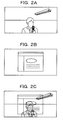
- FIG. 2A is a conceptual diagram of an image that is background reflected on the display unit 5.
- FIG. 2B is a conceptual diagram of a display image that is displayed by the display unit 5.
- FIG. 2C is a conceptual diagram of the first synthesized image. As illustrated in FIGs. 2A through 2C , the first synthesized image is generated based on an image that is caught by the imaging unit 2 (estimated background reflection image) and a screenshot of a display image of the display unit 5.
- the embedding unit 3 controls, for example, signal intensity.
- the embedding unit 3 may apply a method of embedding signal intensity high in a contour region and in a complex texture region with many edges of the first synthesized image and embedding signal intensity low in a relatively smooth region like a background color.
- a method of adjusting the signal intensity may be performed by adjusting, for example, amplitude.
- the embedding unit 3 calculates, for example, average values of luminance and color difference of the entire display screen and analyzes an average frequency in the time direction, and since it is difficult to be visually recognized by the user even with high signal intensity in a high frequency region, in other words, in a region of rapid motion and the like, it is possible to embed by controlling signal intensity high. In contrast, in a low frequency region, in other words, in a region of small motion, high signal intensity is prone to be visually recognized by the user, so that embedding is carried out by controlling the signal intensity as low as possible.
- the embedding unit 3 may appropriately use a threshold (may also be referred to as a first threshold or a second threshold) as desired.
- a threshold may also be referred to as a first threshold or a second threshold
- the luminance value may be set as 125.
- the frequency may be set as 125 Hz.
- the embedding unit 3 may also control the signal intensity in accordance with the luminance value of the first synthesized image without using the threshold (for example, using proportional relationship).
- the embedding unit 3 is may also apply, as disclosed in Japanese Patent No. 4260781 , for example, a method of controlling signal intensity, by determining whether or not an arbitrary region has a specific color component, based on a determination result.
- a test pattern such as a color bar, or the like is displayed on the display unit 5 as initial evaluation, and then an image signal with the converted connection information is superimposed to create a table having a color component that is easily visible by subjective evaluation as the specific color component, which may be held in a cache or a memory, not illustrated, of the embedding unit 3.
- the embedding unit 3 refers to the table and controls (shifts) the signal intensity highly in a region of, for example, a color component closer to the specific color component (for example, white close to the color component of illumination light by a fluorescent lamp). Further, the embedding unit 3 may also perform, as a method of controlling an image signal with converted connection information, for example, control to embed an image signal in a region other than the region of the first synthesized image that becomes at the above threshold or more.
- the embedding unit 3 embeds the controlled image signal by superposition on the display image displayed by the display unit 5 according to the following expression.
- X ⁇ X + ⁇ W
- X is the screenshot of the display image on the display unit 5
- W is the controlled image signal
- X' is the display image displayed by the display unit 5 (an image that is caught by the mobile terminal having an imaging lens)
- ⁇ is, similar to the above expression 1, the ratio of synthesis and is an arbitrary value in a range from 0 to 1.
- the image signal with the converted connection information is controlled by considering not only details of the content but also the influence of the background reflection, so that it becomes possible to suppress a decrease in detection precision of the connection information by the mobile terminal having a lens that images the display image.
- the embedding unit 3 may also generate the first synthesized image based on positional relationship of the imaging unit 2 and the display unit 5, in other words, a first distance and a first angle between the imaging unit 2 and an arbitrary reference point of the display unit 5. For example, in a case that the imaging unit 2 is arranged near upper center or near lower center of the display unit 5, the image caught by the imaging unit 2 and the image background reflected on the display unit 5 become approximately identical, so that special control is not desired, while in a case that the imaging unit 2 and the display unit 5 are arranged apart, based on the first distance and the first angle, the first synthesized image may be generated by appropriately correcting the positional relationship.
- the first distance and the first angle may be defined in advance and carried in a cache or a memory, not illustrated, of the embedding unit 3.
- the embedding unit 3 outputs the display image obtained by controlling the image signal with the converted connection information to the display unit 5.
- the display unit 5 is a display device, such as a liquid crystal display or an organic electroluminescent display, for example.
- the display unit 5 may also be a display device, such as a projector, for example. Further, the display unit 5 may also be formed integrally with the imaging unit 2 and may also be formed separately from the imaging unit 2.
- the display unit 5 accepts the display image with the controlled connection information from the embedding unit 3 and displays the display image.
- the display unit 5 does not have to be included in the image processing device 1 in all cases. For example, it is also possible to equip the display unit 5 in an external device other than the image processing device 1 via a communication line using a communication unit, not illustrated, that is equipped in the image processing device 1.
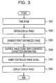
- FIG. 3 is a flowchart of an image processing method with the image processing device 1.
- the imaging unit 2 images an image containing, for example, an imaging lens of a camera belonging to a mobile terminal carried by a user that, for example, images a display image to be displayed by the display unit 5 (step S301).
- the imaging unit 2 outputs the caught image to the embedding unit 3.
- the embedding unit 3 accepts the image from the imaging unit 2.
- the embedding unit 3 also obtains the display image by accessing the recording unit 4 (step S302).
- the embedding unit 3 generates a first synthesized image using the above method from the image accepted from the imaging unit 2 (step S303).
- the embedding unit 3 controls an image signal with converted connection information to be embedded in the first synthesized image (step S304).
- the control method as described above, it is possible to apply a method of embedding signal intensity high in a contour region and in a complex texture region with many edges of the first synthesized image and embedding signal intensity low in a relatively smooth region like a background color.
- the embedding unit 3 embeds the controlled image signal by superposition on the display image displayed by the display unit 5 according to, for example, the above expression 2 (step S305).
- the embedding unit 3 outputs the display image obtained by controlling the image signal with the converted connection information to the display unit 5.
- the display unit 5 accepts the display image with the controlled image signal from the embedding unit 3 to display the display image (step S306), thereby the image processing device 1 completing the process illustrated in FIG. 3 .
- the image processing device 1 may also repeatedly execute the process disclosed in step S301 through step S306.
- the image processing device in the first embodiment it is possible to reduce the influence of a noise due to disturbance. Specifically, utilizing an image taken by the imaging unit 2, background reflection occurs (on the display surface) in the display unit 5 is estimated, and utilizing the estimated image and the display image displayed by the display unit 5, the image signal of the connection information is controlled. This improves the detection precision of the connection information that becomes difficult to be detected due to the various influence of the background reflection by, for example, illumination light, natural light, and the like.
- the first embodiment in a case that a user, for example, carrying a mobile terminal having a lens that images a display image is located approximately in front of the display unit 5, a higher effect is yielded.
- the second embodiment descriptions are given to a case that the user is located other than approximately in front of the display unit 5, for example, diagonally in front.
- process to estimate positional relationship of objects such as a position of an imaging lens that is mounted in a mobile terminal carried by the user, a position of the display unit 5, and a fluorescent lamp to be a source of generation of illumination light, is performed.
- Technical significance of the process is as follows.
- the position of, for example, a fluorescent lamp contained in the image that is caught by the imaging unit 2 becomes regular all the time unless the position or the range of imaging by the imaging unit 2 is changed.
- the image that is background reflected on the display unit 5 in the viewpoint of the imaging lens that images a display image changes depending on the position of the imaging lens. This is because background reflection occurs in a region where an incident angle of illumination light of the fluorescent lamp to the display unit 5 becomes equal to a reflection angle from the display unit 5 to the imaging lens. Therefore, there is a demand for the process to estimate positional relationship of objects, such as a position of the imaging lens, a position of the display unit 5, and a fluorescent lamp to be a source of generation of illumination light and the like.
- Detailed descriptions are given below to embodiments of an image processing device, an image processing method, and an image processing program in the second embodiment including the process based on the drawings. It is to be noted that these embodiments do not limit embodiments of the disclosed technique.
- FIG. 4 is a functional block diagram of an image processing device 1 according to the second embodiment.
- the image processing device 1 has an imaging unit 2, an embedding unit 3, a recording unit 4, a display unit 5, a calculation unit 6, a shaping unit 7, and a generation unit 8.
- the image processing device 1 may also be configured with an integrated circuit, such as an application specific integrated circuit (ASIC) and a field programmable gate array (FPGA), for example.
- ASIC application specific integrated circuit
- FPGA field programmable gate array
- the imaging unit 2 outputs a caught image to the calculation unit 6, the shaping unit 7, and the generation unit 8.
- the calculation unit 6 is, for example, a hardware circuit by wired logic.
- the calculation unit 6 may also be a functional module that is achieved by a computer program executed in the image processing device 1.
- the calculation unit 6 accepts the image from the imaging unit 2.
- the calculation unit 6 calculates a second angle between an object contained in the image and an arbitrary reference point of the display unit 5.
- the object contained in the image is an object that is referred to using, for example, noun, such as a fluorescent lamp, an air conditioner, and a crock.
- the arbitrary reference point of the display unit 5 may be set, for example, near upper center of the display unit 5 and may also be set in another arbitrary reference point. Further, the calculation unit 6 calculates a third angle between the reference point of the display unit 5 contained in the image and the imaging lens contained in the image.
- a method of specifying the imaging lens contained in the image allows specification of the imaging lens by holding an image containing an imaging lens in advance to use template matching.
- the calculation unit 6 further calculates a second distance between the reference point of the display unit 5 and the object contained in the image.
- the calculation unit 6 may use, for example, a ranging sensor, not illustrated, that the calculation unit 6 is able to contain.
- the calculation unit 6 may calculate the second distance based on detection information of the ranging sensor in, for example, a TOF format to measure a depth from a round trip time of a laser beam, a pattern radiation format to measure distortion in a pattern of light when radiated to a laser beam in a specific pattern, and the like. Further, the calculation unit 6 may calculate the second distance using, for example, a method described in U.S. Patent Application Publication No. 2010/0118123 A1 .
- the calculation unit 6 does not have to include a ranging sensor.
- the calculation unit 6 may calculate the second distance by the triangulation principle based on, for example, parallax between a plurality of images caught by the stereo camera.
- the calculation unit 6 may also calculate the second distance using, for example, a method described in Japanese Patent No. 4155780 or Japanese Patent No. 4198054 .
- the calculation unit 6 outputs the second distance, the second angle, and the third angle thus calculated to the shaping unit 7.
- the shaping unit 7 is, for example, a hardware circuit by wired logic.
- the shaping unit 7 may also be a functional module that is achieved by a computer program executed in the image processing device 1.
- the shaping unit 7 accepts the second distance, the second angle, and the third angle from the calculation unit 6 and accepts the image from the imaging unit 2.
- the shaping unit 7 shapes a depth map of an object in the viewpoint of the imaging lens contained in the image that is caught by the imaging unit 2 based on the second distance, the second angle, and the third angle using various approaches in the past.
- the imaging unit 2 is an imaging device including two or more cameras, such as a stereo camera, an image obtained by averaging the plurality of images that are caught by the stereo camera, for example, may be used.
- the shaping unit 7 outputs the depth map thus shaped to the generation unit 8.
- FIG. 5 is a conceptual diagram of positional relationship of the imaging unit 2, the display unit 5, the imaging lens, and the object.
- the origin of coordinates is set at the center of the imaging unit 2 that is arranged near upper center of the display unit 5.
- an ID is given for convenience of description in the second embodiment.
- An ID1 is an imaging lens belonging to a mobile terminal carried by the user
- an ID2 is fluorescent lamps to be one example of the object. Although other objects are contained in the image, descriptions are given using the fluorescent lamps only for convenience of description.
- FIG. 6 is one example of a table including data generated by the shaping unit 7.
- the generation unit 8 in FIG. 4 is, for example, a hardware circuit by wired logic.
- the generation unit 8 may also be a functional module that is achieved by a computer program executed in the image processing device 1.
- the generation unit 8 accepts the depth map from the shaping unit 7 and accepts the image from the imaging unit 2.
- the generation unit 8 rotates the depth map based on the third angle, and then generates a superimposed image in which a first pixel described above is superimposed.
- the generation unit 8 rotates the depth map accepted from the shaping unit 7 based on the second distance, the second angle, or the third angle, and then pastes the image accepted from the imaging unit 2 using, for example, a relief texture mapping approach taking the first pixel value described above as a texture.
- the generation unit 8 may use a method of relief texture mapping, for example, disclosed in " Manuel M. Oliveria, Gary Bishop, David McAllister, "Relief texture mapping", SIGGRAPH2000 Proceedings of the 27th annual conference on Computer graphics and interactive techniques, 359-368, 2000 ".
- the generation unit 8 generates a superimposed image (may also be referred to as a 3D object) by using the method. It also becomes possible to generate a superimposed image with small occlusion and of higher resolution by increasing a number of cameras in the imaging unit 2.
- the generation unit 8 outputs the superimposed image thus generated to the embedding unit 3.
- the embedding unit 3 is, for example, a hardware circuit by wired logic similar to the first embodiment.
- the embedding unit 3 may also be a functional module that is achieved by a computer program executed in the image processing device 1.
- the embedding unit 3 accepts the superimposed image from the generation unit 8.
- the embedding unit 3 generates a second synthesized image in which the superimposed image is synthesized on a screenshot of a display image.
- the embedding unit 3 controls an image signal with converted connection information in a region where the first pixel value, the second pixel value, or an amount of change in the second pixel value of the second synthesized image becomes a predetermined first threshold or more. Regarding the control method, it is possible to carry out process similar to the process to the first synthesized image disclosed in the first embodiment.
- the embedding unit 3 outputs the display image obtained by controlling the image signal to the display unit 5.
- the display unit 5 accepts the display image with the controlled connection information from the embedding unit 3 to display the display image.
- the image processing device in the second embodiment it is possible to reduce the influence of a noise due to disturbance.
- background reflection occurring (on the display surface) in the display unit 5 is estimated utilizing the image taken by the imaging unit 2 to control the image signal of the connection information utilizing the estimated image and the display image displayed by the display unit 5.
- This improves the detection precision of the connection information that becomes difficult to be detected by the various influence of the background reflection due to, for example, illumination light, natural light, and the like.
- a background reflection image on the display unit 5 is estimated in the viewpoint of the lens that images the display image, so that it is possible to estimate background reflection with very high precision.
- the second distance is calculated in the second embodiment, the second distance does not have to be calculated in all cases.
- the image processing device 1 may also estimate a rough background reflection image on the display unit 5 in the viewpoint of the lens that images the display image only using the second angle and the third angle.
- connection process of an information processing terminal not illustrated, that mounts or connects an image processing device 1 and a mobile terminal having an imaging lens carried by a user.
- a display unit 5 displays a display image with connection information, for example, that is disclosed in the first embodiment or the second embodiment embedded therein.
- the user carrying the mobile terminal having the imaging lens images a display image with connection information embedded therein to be displayed by the display unit 5.
- the mobile terminal is connected to the information processing terminal via a network based on the connection information.
- the mobile terminal may also send an image caught by the imaging lens of the mobile terminal to an arbitrary server, and the server that receives the image may decode the connection information from the image for sending to the mobile terminal.
- the information processing terminal and the mobile terminal that have completed the connection process carry out sending and receiving of, for example, various contents (moving images, still images, document data, and the like) belonging to the information processing terminal via a network.
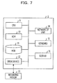
- FIG. 7 is a hardware configuration diagram of a computer that functions as an image processing device 1 according to one embodiment.
- the image processing device 1 includes a CPU 9, a ROM 10, an HDD 11, a drive device 12, a network I/F unit 14, a keyboard 15, and a display 16. Each of these components is connected to each other via a bus to allow data input/output.
- the CPU 9 is an arithmetic device to carry out control of each device, and arithmetic operation and processing of data in a computer.
- the CPU 9 is also an arithmetic device to execute a program recorded in the ROM 10 and the HDD 11, and accepts data from the keyboard 15 and a recording device for arithmetic operation and processing and then outputs the data to the display 16, a recording device, and the like.
- the ROM 10 is a read-only memory and is a recording device to record or temporarily store a program, such as an OS, which is basic software executed by the CPU 9, and application software, and data. It is also possible to apply a RAM instead of the ROM.
- the HDD 11 is a recording device to record data related with application software and the like.
- the drive device 12 reads a program out of a recording medium 13, for example, a flexible disk for installation in the HDD 11.
- a predetermined program is stored in the recording medium 13, and the program stored in the recording medium 13 is installed in the image processing device 1 via the drive device 12.
- the installed predetermined program becomes available to be executed by the image processing device 1.
- the network I/F unit 14 is an interface between the image processing device 1 and a peripheral instrument having a communication function connected via a network, such as a local area network (LAN) and a wide area network (WAN), that is constructed by a data transmission channel, such as a wired and/or wireless line.
- a network such as a local area network (LAN) and a wide area network (WAN)
- WAN wide area network
- the keyboard 15 is an input instrument provided with a cursor key, numeric input and various functional keys, and the like. It is also possible to apply a mouse, a slicepad, and the like to carry out selection of a key and the like on the display screen of the display 16 instead of a keyboard as an input instrument.
- the keyboard 15 is a user interface for a user to give an operation instruction and to input data to the CPU 9.
- the function of the display 16 at least has a function similar to the display unit 5 disclosed in the first embodiment or the second embodiment, detailed descriptions are omitted. Display in accordance with the display data inputted from the CPU 9 is carried out.
- the image processing method described above may also be achieved as a program to be executed in a computer.
- the program is installed from a server or the like to be executed in a computer, thereby enabling to achieve the image processing method described above.
- recording medium 13 various types of recording medium may be used, such as a recording medium to optically, electrically, or magnetically record information, like a CD-ROM, a flexible disk, and a magnetooptical disk, and a semiconductor memory to electrically record information, like a ROM and a flash memory.
- a recording medium to optically, electrically, or magnetically record information like a CD-ROM, a flexible disk, and a magnetooptical disk
- semiconductor memory to electrically record information, like a ROM and a flash memory.
- each device illustrated above do not have to be physically configured as the illustration in all cases. That is, the specific mode of separation and integration in each device is not limited to the illustration, and all or part thereof may be configured by separating or integrating functionally or physically in an arbitrary unit in accordance with various types of load, status of use, and the like.
- the various types of process described in the above embodiments may be achieved by executing a program in a computer prepared in advance, such as a personal computer and a workstation.
Landscapes
- Physics & Mathematics (AREA)
- General Physics & Mathematics (AREA)
- Engineering & Computer Science (AREA)
- Theoretical Computer Science (AREA)
- Image Processing (AREA)
- Studio Devices (AREA)
Abstract
Description
- The embodiments discussed herein are related to, for example, an image processing device, and an image processing method to control display information.
- In order to download a specific content to a terminal that is owned by a user him/herself, the user sometimes accesses a device to record various contents, such as a personal computer (PC), a digital signage terminal, a KIOSK terminal, and a smartphone, via a communication network. In order to achieve such access, a user has to acquire connection information to specify the device to record a content intended to be downloaded over a communication network. The connection information is information, such as an Internet protocol (IP) address, a service set identifier (SSID), Bluetooth® ID, and a uniform resource locator (URL), for example.
- With that, Japanese Laid-open Patent Publication No.
2011-205485 2004-194236 - In the above technique to embed connection information in a display image, in order not to degrade the visibility of the display image, the connection information has to be an image signal that is difficult for a user to visually recognize (for example, an image signal with signal intensity set low). However, in a case of imaging an image signal with low signal intensity, it is important to reduce influence of a noise due to disturbance from the perspective of securing quality, such as a signal to noise ratio (SNR). It is desired to provide an image processing device that enables the reduction of influence of a noise due to disturbance.
- In accordance with an aspect of the embodiments, an image processing device includes a computer processor, the device includes an image processing device includes an imaging unit configured to take an image containing an imaging lens; and an embedding unit configured to embed information in a display image based on image information of an object contained in the image.
- The object and advantages of the invention will be realized and attained by means of the elements and combinations particularly pointed out in the claims. It is to be understood that both the foregoing general description and the following detailed description are exemplary and explanatory and are not restrictive of the invention, as claimed.
- The image processing device disclosed herein enables the reduction of influence of a noise due to disturbance.
- These and/or other aspects and advantages will become apparent and more readily appreciated from the following description of the embodiments, taken in conjunction with the accompanying drawing of which:
-
FIG. 1 is a functional block diagram of an image processing device according to a first embodiment; -
FIG. 2A is a conceptual diagram of an image that is background reflected on a display unit,FIG. 2B is a conceptual diagram of a display image that is displayed by the display unit, andFIG. 2C is a conceptual diagram of a first synthesized image; -
FIG. 3 is a flowchart of an image processing method with an image processing device; -
FIG. 4 is a functional block diagram of an image processing device according to a second embodiment; -
FIG. 5 is a conceptual diagram of positional relationship of an imaging unit, a display unit, an imaging lens, and an object; -
FIG. 6 is one example of a table containing data generated by a shaping unit; and -
FIG. 7 is a hardware configuration diagram of a computer that functions as an image processing device according to one embodiment. - Keen studies by the present inventors have revealed the following problems in the technique to embed connection information in a display image. When imaging a display image, due to influence of an ambient illumination environment, a phenomenon in which a user and objects surrounding the user are background reflected on a display surface of a display unit (for example, a display of a laptop personal computer) occurs. In this case, because the background reflection is superimposed on the display image with the connection information embedded therein as a noise due to disturbance, it is revealed that detection of the connection information becomes difficult. Therefore, by reducing the influence of the background reflection, it is expected to enable detection of the connection information.
- Descriptions are given below to embodiments of an image processing device, an image processing method, and an image processing program according to one embodiment based on the drawings. These embodiments do not limit embodiments of the disclosed technique.
-
FIG. 1 is a functional block diagram of animage processing device 1 according to a first embodiment. Theimage processing device 1 has animaging unit 2, anembedding unit 3, arecording unit 4, and adisplay unit 5. Theimage processing device 1 may also be configured with an integrated circuit, such as an application specific integrated circuit (ASIC) and a field programmable gate array (FPGA), for example. - The
imaging unit 2 is an imaging device, such as a charge coupled device (CCD) or complementary metal oxide semiconductor (CMOS) camera, for example. Theimaging unit 2 images an image containing, for example, an imaging lens of a camera belonging to a mobile terminal carried by the user that images a display image displayed by thedisplay unit 5 described later, for example. Theimaging unit 2 is arranged, for example, in a mode of being built in thedisplay unit 5 or in a mode of being attached externally. Theimaging unit 2 does not have to be included in theimage processing device 1 in all cases. For example, it is also possible to equip theimaging unit 2 in an external device other than theimage processing device 1 via a communication line using a communication unit, not illustrated, that is equipped in theimage processing device 1. Further, theimaging unit 2 may also be an imaging device including two or more cameras, such as a stereo camera. Theimaging unit 2 outputs the caught image to theembedding unit 3. - The
embedding unit 3 is, for example, a hardware circuit by wired logic. Theembedding unit 3 may also be a functional module that is achieved by a computer program executed in theimage processing device 1. Theembedding unit 3 accepts the image from theimaging unit 2. Theembedding unit 3 converts connection information (may also be referred to simply as information), such as an IP address and a service set identifier (SSID), that is desired by a mobile terminal carried by the user to, for example, an image signal to embed in a display image to be displayed by thedisplay unit 5 based on image information of an object contained in the image. The image information of the object may be, for example, a luminance value (may also be referred to as a first pixel value) in the RGB color space. - The
embedding unit 3 may utilize a technique in the past, such as a watermark technique disclosed in Japanese Laid-open Patent Publication No.2012-142741 embedding unit 3 may embed an image signal using alpha blending, for example, taking a pattern to change an area in the time direction as an image signal. Here, the image signal is, for example, a periodic signal, such as a sine wave and a triangular wave containing binary information in which one represents a value of "0" and the other represents a value of "1", and theembedding unit 3 may embed, for example, an image signal to be connection information by phase modulation in a display image. - The display image is an image of an arbitrary content, such as an image, a still image, or a document contained in moving image data, for example, and is recorded in the
recording unit 4 described later, for example. Theembedding unit 3 may obtain a display image by accessing therecording unit 4. Theembedding unit 3 may also capture an image displayed by thedisplay unit 5 described later using, for example, functions of an operation system (OS) that is mountable in theimage processing device 1 as a display image. Theembedding unit 3 may obtain a display image of a still image by utilizing an application programming interface (API) of the OS and the like, for example. Further, in a case that there is any alteration in the image displayed by thedisplay unit 5, theembedding unit 3 may obtain a notification from the OS to obtain a screenshot of the display image taking the obtainment of the notification as an opportunity, and may also obtain a screenshot of the display image at regular intervals, such as once per second. In in a case that thedisplay unit 5 displays moving image data and the like, theembedding unit 3 may also obtain a screenshot of the display image in conformity with a frame rate of the moving image data. Theembedding unit 3 may obtain a screenshot of the display image per 1/30 second in a case that, for example, a frame rate of the moving image data is 30 fps. - The
recording unit 4 is, for example, a semiconductor memory element, such as a flash memory, or a recording device, such as a hard disk drive (HDD), a flash solid state drive (SSD), and an optical disk. Therecording unit 4 is not limited to the recording device of the types mentioned above, and may also be a random access memory (RAM) and a read only memory (ROM). In therecording unit 4, a display image, which is an image contained in an arbitrary content, such as moving image data, a still image, or a document, for example, is recorded. Therecording unit 4 does not have to be included in theimage processing device 1 in all cases. For example, the display image may also be recorded in a cache, a memory, and the like, not illustrated, in each functional unit included in theimage processing device 1. It is also possible to equip therecording unit 4 in an external device other than theimage processing device 1 via a communication line using a communication unit, not illustrated, that is equipped in theimage processing device 1. - Next, the embedding
unit 3 controls an image signal with the converted connection information based on the first pixel value described above and, for example, a luminance value in the RGB color space (may also be referred to as a second pixel value) contained in the display image or an amount of change in the second pixel value per unit time to embed in the display image. Specifically, first of all, the embeddingunit 3 generates a first synthesized image in which, for example, the image accepted from theimaging unit 2 is synthesized on a screenshot of a display image obtained from therecording unit 4. - Here, descriptions are given to technical significance to generate the first synthesized image. In the first embodiment, descriptions are given to, for example, a case that the
imaging unit 2 is arranged near upper center or near lower center of thedisplay unit 5 and also a case that the user carrying the mobile terminal having a lens to image a display image to be displayed by thedisplay unit 5 is located approximately in front of thedisplay unit 5. When the (display surface of the)display unit 5 is assumed to be a reflective surface of ambient illumination light and natural light, the first synthesized image in which an image caught by theimaging unit 2 and a display image to be displayed by thedisplay unit 5 are synthesized may be regarded as a display image that is caught by an imaging lens of a mobile terminal carried by the user in which background reflection occurs actually. Based on the first synthesized image, an image signal with the converted connection information is controlled so as to suppress the influence of the background reflection, thereby enabling to accurately detect connection information. - In the generation of the first synthesized image, a ratio of synthesizing the image caught by the
imaging unit 2 and the display image depends on the reflectivity of a material used for the (display surface of the)display unit 5, so that the embeddingunit 3 may also preset an appropriate ratio by initial evaluation. For example, the ratio of the image caught by the imaging unit 2 (may also be referred to as an estimated background reflection image) may be set high in a case of high reflectivity, and the ratio of the display image may be set high in a case of low reflectivity. - The embedding
unit 3 generates the first synthesized image in the alpha blending method expressed by, for example, the following expression from the image accepted from theimaging unit 2 and the display image.
- In the
above expression 1, X is the screenshot of the display image of thedisplay unit 5, Y is the image that is caught by the imaging unit 2 (estimated background reflection image), Z is the first synthesized image in which the two images are synthesized, and α is the ratio of synthesis and is an arbitrary value in a range from 0 to 1. A greater α value causes a greater ratio of Y, so that the value of α may be set greater as, for example, the (display surface of the)display unit 5 has greater reflectance. The specific numerical value to be set in α may be, for example, held in a cache or a memory, not illustrated, of the embeddingunit 3 by creating a conversion table in which the reflectance is associated with the α value by initial evaluation. -
FIG. 2A is a conceptual diagram of an image that is background reflected on thedisplay unit 5.FIG. 2B is a conceptual diagram of a display image that is displayed by thedisplay unit 5.FIG. 2C is a conceptual diagram of the first synthesized image. As illustrated inFIGs. 2A through 2C , the first synthesized image is generated based on an image that is caught by the imaging unit 2 (estimated background reflection image) and a screenshot of a display image of thedisplay unit 5. - Next, as control (shift) of the image signal to be embedded in the first synthesized image, the embedding
unit 3 controls, for example, signal intensity. As a control method, the embeddingunit 3 may apply a method of embedding signal intensity high in a contour region and in a complex texture region with many edges of the first synthesized image and embedding signal intensity low in a relatively smooth region like a background color. A method of adjusting the signal intensity may be performed by adjusting, for example, amplitude. Specifically, in a case that a display image is contained in moving image data, the embeddingunit 3 calculates, for example, average values of luminance and color difference of the entire display screen and analyzes an average frequency in the time direction, and since it is difficult to be visually recognized by the user even with high signal intensity in a high frequency region, in other words, in a region of rapid motion and the like, it is possible to embed by controlling signal intensity high. In contrast, in a low frequency region, in other words, in a region of small motion, high signal intensity is prone to be visually recognized by the user, so that embedding is carried out by controlling the signal intensity as low as possible. Further, in order to control the image signal with the converted connection information, the embeddingunit 3 may appropriately use a threshold (may also be referred to as a first threshold or a second threshold) as desired. As the first threshold, the luminance value may be set as 125. As the second threshold, the frequency may be set as 125 Hz. The embeddingunit 3 may also control the signal intensity in accordance with the luminance value of the first synthesized image without using the threshold (for example, using proportional relationship). - The embedding
unit 3 is may also apply, as disclosed in Japanese Patent No.4260781 display unit 5 as initial evaluation, and then an image signal with the converted connection information is superimposed to create a table having a color component that is easily visible by subjective evaluation as the specific color component, which may be held in a cache or a memory, not illustrated, of the embeddingunit 3. The embeddingunit 3 refers to the table and controls (shifts) the signal intensity highly in a region of, for example, a color component closer to the specific color component (for example, white close to the color component of illumination light by a fluorescent lamp). Further, the embeddingunit 3 may also perform, as a method of controlling an image signal with converted connection information, for example, control to embed an image signal in a region other than the region of the first synthesized image that becomes at the above threshold or more. - Next, the embedding
unit 3 embeds the controlled image signal by superposition on the display image displayed by thedisplay unit 5 according to the following expression.
- In the described
expression 2, X is the screenshot of the display image on thedisplay unit 5, W is the controlled image signal, X' is the display image displayed by the display unit 5 (an image that is caught by the mobile terminal having an imaging lens), and α is, similar to theabove expression 1, the ratio of synthesis and is an arbitrary value in a range from 0 to 1. - Here, descriptions are given to technical significance of embedding process in the embedding
unit 3. In a case that the display screen in which background reflection occurs is caught from a position of the imaging lens of the mobile terminal carried by the user, imaging is carried out as a video in which a display image contained in the original content and the background reflection are synthesized. Therefore, the display image displayed by thedisplay unit 5 becomes difficult to be visually recognized due to the influence of the background reflection, and this signifies that the signal intensity of the embedded image signal that is embedded in the display screen becomes low together as well. Therefore, even when the signal intensity is made higher than a case in which background reflection does not occur, the image signal with the converted connection information becomes difficult to be visually recognized by eyes of the user. - According to the embedding process to the first synthesized image in the embedding
unit 3, the image signal with the converted connection information is controlled by considering not only details of the content but also the influence of the background reflection, so that it becomes possible to suppress a decrease in detection precision of the connection information by the mobile terminal having a lens that images the display image. - The embedding
unit 3 may also generate the first synthesized image based on positional relationship of theimaging unit 2 and thedisplay unit 5, in other words, a first distance and a first angle between theimaging unit 2 and an arbitrary reference point of thedisplay unit 5. For example, in a case that theimaging unit 2 is arranged near upper center or near lower center of thedisplay unit 5, the image caught by theimaging unit 2 and the image background reflected on thedisplay unit 5 become approximately identical, so that special control is not desired, while in a case that theimaging unit 2 and thedisplay unit 5 are arranged apart, based on the first distance and the first angle, the first synthesized image may be generated by appropriately correcting the positional relationship. The first distance and the first angle may be defined in advance and carried in a cache or a memory, not illustrated, of the embeddingunit 3. The embeddingunit 3 outputs the display image obtained by controlling the image signal with the converted connection information to thedisplay unit 5. - The
display unit 5 is a display device, such as a liquid crystal display or an organic electroluminescent display, for example. Thedisplay unit 5 may also be a display device, such as a projector, for example. Further, thedisplay unit 5 may also be formed integrally with theimaging unit 2 and may also be formed separately from theimaging unit 2. Thedisplay unit 5 accepts the display image with the controlled connection information from the embeddingunit 3 and displays the display image. Thedisplay unit 5 does not have to be included in theimage processing device 1 in all cases. For example, it is also possible to equip thedisplay unit 5 in an external device other than theimage processing device 1 via a communication line using a communication unit, not illustrated, that is equipped in theimage processing device 1. -
FIG. 3 is a flowchart of an image processing method with theimage processing device 1. Theimaging unit 2 images an image containing, for example, an imaging lens of a camera belonging to a mobile terminal carried by a user that, for example, images a display image to be displayed by the display unit 5 (step S301). Theimaging unit 2 outputs the caught image to the embeddingunit 3. - The embedding
unit 3 accepts the image from theimaging unit 2. The embeddingunit 3 also obtains the display image by accessing the recording unit 4 (step S302). Next, the embeddingunit 3 generates a first synthesized image using the above method from the image accepted from the imaging unit 2 (step S303). - The embedding
unit 3 controls an image signal with converted connection information to be embedded in the first synthesized image (step S304). As one example of the control method, as described above, it is possible to apply a method of embedding signal intensity high in a contour region and in a complex texture region with many edges of the first synthesized image and embedding signal intensity low in a relatively smooth region like a background color. - The embedding
unit 3 embeds the controlled image signal by superposition on the display image displayed by thedisplay unit 5 according to, for example, the above expression 2 (step S305). The embeddingunit 3 outputs the display image obtained by controlling the image signal with the converted connection information to thedisplay unit 5. - The
display unit 5 accepts the display image with the controlled image signal from the embeddingunit 3 to display the display image (step S306), thereby theimage processing device 1 completing the process illustrated inFIG. 3 . In a case that theimaging unit 2 continues to catch an image, theimage processing device 1 may also repeatedly execute the process disclosed in step S301 through step S306. - According to the image processing device in the first embodiment, it is possible to reduce the influence of a noise due to disturbance. Specifically, utilizing an image taken by the
imaging unit 2, background reflection occurs (on the display surface) in thedisplay unit 5 is estimated, and utilizing the estimated image and the display image displayed by thedisplay unit 5, the image signal of the connection information is controlled. This improves the detection precision of the connection information that becomes difficult to be detected due to the various influence of the background reflection by, for example, illumination light, natural light, and the like. - In the first embodiment in a case that a user, for example, carrying a mobile terminal having a lens that images a display image is located approximately in front of the
display unit 5, a higher effect is yielded. In the second embodiment, descriptions are given to a case that the user is located other than approximately in front of thedisplay unit 5, for example, diagonally in front. In the second embodiment, in order to estimate a background reflection image on thedisplay unit 5 in the viewpoint of the lens that images a display image, process to estimate positional relationship of objects, such as a position of an imaging lens that is mounted in a mobile terminal carried by the user, a position of thedisplay unit 5, and a fluorescent lamp to be a source of generation of illumination light, is performed. Technical significance of the process is as follows. The position of, for example, a fluorescent lamp contained in the image that is caught by theimaging unit 2 becomes regular all the time unless the position or the range of imaging by theimaging unit 2 is changed. In contrast, the image that is background reflected on thedisplay unit 5 in the viewpoint of the imaging lens that images a display image changes depending on the position of the imaging lens. This is because background reflection occurs in a region where an incident angle of illumination light of the fluorescent lamp to thedisplay unit 5 becomes equal to a reflection angle from thedisplay unit 5 to the imaging lens. Therefore, there is a demand for the process to estimate positional relationship of objects, such as a position of the imaging lens, a position of thedisplay unit 5, and a fluorescent lamp to be a source of generation of illumination light and the like. Detailed descriptions are given below to embodiments of an image processing device, an image processing method, and an image processing program in the second embodiment including the process based on the drawings. It is to be noted that these embodiments do not limit embodiments of the disclosed technique. -
FIG. 4 is a functional block diagram of animage processing device 1 according to the second embodiment. Theimage processing device 1 has animaging unit 2, an embeddingunit 3, arecording unit 4, adisplay unit 5, acalculation unit 6, ashaping unit 7, and ageneration unit 8. Theimage processing device 1 may also be configured with an integrated circuit, such as an application specific integrated circuit (ASIC) and a field programmable gate array (FPGA), for example. - Since the function of the
imaging unit 2 at least has a function similar to the first embodiment, detailed descriptions are omitted. Theimaging unit 2 outputs a caught image to thecalculation unit 6, theshaping unit 7, and thegeneration unit 8. Thecalculation unit 6 is, for example, a hardware circuit by wired logic. Thecalculation unit 6 may also be a functional module that is achieved by a computer program executed in theimage processing device 1. Thecalculation unit 6 accepts the image from theimaging unit 2. Thecalculation unit 6 calculates a second angle between an object contained in the image and an arbitrary reference point of thedisplay unit 5. The object contained in the image is an object that is referred to using, for example, noun, such as a fluorescent lamp, an air conditioner, and a crock. The arbitrary reference point of thedisplay unit 5 may be set, for example, near upper center of thedisplay unit 5 and may also be set in another arbitrary reference point. Further, thecalculation unit 6 calculates a third angle between the reference point of thedisplay unit 5 contained in the image and the imaging lens contained in the image. A method of specifying the imaging lens contained in the image allows specification of the imaging lens by holding an image containing an imaging lens in advance to use template matching. - Next, the
calculation unit 6 further calculates a second distance between the reference point of thedisplay unit 5 and the object contained in the image. In order to calculate the second distance, thecalculation unit 6 may use, for example, a ranging sensor, not illustrated, that thecalculation unit 6 is able to contain. Thecalculation unit 6 may calculate the second distance based on detection information of the ranging sensor in, for example, a TOF format to measure a depth from a round trip time of a laser beam, a pattern radiation format to measure distortion in a pattern of light when radiated to a laser beam in a specific pattern, and the like. Further, thecalculation unit 6 may calculate the second distance using, for example, a method described inU.S. Patent Application Publication No. 2010/0118123 A1 . - In calculation of the second distance, in a case that the
imaging unit 2 is an imaging device including two or more cameras, such as a stereo camera, thecalculation unit 6 does not have to include a ranging sensor. Thecalculation unit 6 may calculate the second distance by the triangulation principle based on, for example, parallax between a plurality of images caught by the stereo camera. Thecalculation unit 6 may also calculate the second distance using, for example, a method described in Japanese Patent No.4155780 4198054 calculation unit 6 outputs the second distance, the second angle, and the third angle thus calculated to theshaping unit 7. - The
shaping unit 7 is, for example, a hardware circuit by wired logic. Theshaping unit 7 may also be a functional module that is achieved by a computer program executed in theimage processing device 1. Theshaping unit 7 accepts the second distance, the second angle, and the third angle from thecalculation unit 6 and accepts the image from theimaging unit 2. Theshaping unit 7 shapes a depth map of an object in the viewpoint of the imaging lens contained in the image that is caught by theimaging unit 2 based on the second distance, the second angle, and the third angle using various approaches in the past. In a case that theimaging unit 2 is an imaging device including two or more cameras, such as a stereo camera, an image obtained by averaging the plurality of images that are caught by the stereo camera, for example, may be used. Theshaping unit 7 outputs the depth map thus shaped to thegeneration unit 8. -
FIG. 5 is a conceptual diagram of positional relationship of theimaging unit 2, thedisplay unit 5, the imaging lens, and the object. InFIG. 5 , for example, the origin of coordinates is set at the center of theimaging unit 2 that is arranged near upper center of thedisplay unit 5. InFIG. 5 , although not having to be given in all cases, an ID is given for convenience of description in the second embodiment. An ID1 is an imaging lens belonging to a mobile terminal carried by the user, and an ID2 is fluorescent lamps to be one example of the object. Although other objects are contained in the image, descriptions are given using the fluorescent lamps only for convenience of description. It is possible to appropriately calculate coordinates of the ID1 and the ID2 using, for example, the second distance, the second angle, and the third angle to become, for example, (x1, y1), (x2, y2). Here, objects in a range surrounded by a line segment A' and a line segment B' that are obtained by reflecting a line segment A and a line segment B that join the imaging lens to both ends of thedisplay unit 5 at angles θ2 (= θ1) and θ4 (= θ3) may be estimated to background reflect on the image that is caught by the imaging lens, so that thegeneration unit 8 generates a depth map in the range. In addition, by appropriately calculating an incident angle (reflection angle) of the ID2 to the ID1 taking thedisplay unit 5 as a reflective surface, the coordinates (x3, y0) in which the illumination light is background reflected to thedisplay unit 5 may be calculated. -
FIG. 6 is one example of a table including data generated by theshaping unit 7. As illustrated in a table 60 inFIG. 6 , in the table 60, an ID of an object, coordinates corresponding to the ID, a distance from the origin of coordinates illustrated inFIG. 5 , an angle made by the object to the imaging lens (incident angle = reflection angle) in a case that thedisplay unit 5 is the reflective surface, and coordinates of a region in which background reflection of thedisplay unit 5 occurs that is calculated from the angle are stored as desired. - The
generation unit 8 inFIG. 4 is, for example, a hardware circuit by wired logic. Thegeneration unit 8 may also be a functional module that is achieved by a computer program executed in theimage processing device 1. Thegeneration unit 8 accepts the depth map from theshaping unit 7 and accepts the image from theimaging unit 2. Thegeneration unit 8 rotates the depth map based on the third angle, and then generates a superimposed image in which a first pixel described above is superimposed. Specifically, thegeneration unit 8 rotates the depth map accepted from theshaping unit 7 based on the second distance, the second angle, or the third angle, and then pastes the image accepted from theimaging unit 2 using, for example, a relief texture mapping approach taking the first pixel value described above as a texture. Thegeneration unit 8 may use a method of relief texture mapping, for example, disclosed in "Manuel M. Oliveria, Gary Bishop, David McAllister, "Relief texture mapping", SIGGRAPH2000 Proceedings of the 27th annual conference on Computer graphics and interactive techniques, 359-368, 2000". Thegeneration unit 8 generates a superimposed image (may also be referred to as a 3D object) by using the method. It also becomes possible to generate a superimposed image with small occlusion and of higher resolution by increasing a number of cameras in theimaging unit 2. Thegeneration unit 8 outputs the superimposed image thus generated to the embeddingunit 3. - The embedding
unit 3 is, for example, a hardware circuit by wired logic similar to the first embodiment. The embeddingunit 3 may also be a functional module that is achieved by a computer program executed in theimage processing device 1. The embeddingunit 3 accepts the superimposed image from thegeneration unit 8. The embeddingunit 3 generates a second synthesized image in which the superimposed image is synthesized on a screenshot of a display image. - Next, the embedding
unit 3 controls an image signal with converted connection information in a region where the first pixel value, the second pixel value, or an amount of change in the second pixel value of the second synthesized image becomes a predetermined first threshold or more. Regarding the control method, it is possible to carry out process similar to the process to the first synthesized image disclosed in the first embodiment. The embeddingunit 3 outputs the display image obtained by controlling the image signal to thedisplay unit 5. - Since the function of the
display unit 5 at least has a function similar to the first embodiment, detailed descriptions are omitted. Thedisplay unit 5 accepts the display image with the controlled connection information from the embeddingunit 3 to display the display image. - According to the image processing device in the second embodiment, it is possible to reduce the influence of a noise due to disturbance. Specifically, background reflection occurring (on the display surface) in the
display unit 5 is estimated utilizing the image taken by theimaging unit 2 to control the image signal of the connection information utilizing the estimated image and the display image displayed by thedisplay unit 5. This improves the detection precision of the connection information that becomes difficult to be detected by the various influence of the background reflection due to, for example, illumination light, natural light, and the like. Further, a background reflection image on thedisplay unit 5 is estimated in the viewpoint of the lens that images the display image, so that it is possible to estimate background reflection with very high precision. Although the second distance is calculated in the second embodiment, the second distance does not have to be calculated in all cases. For example, theimage processing device 1 may also estimate a rough background reflection image on thedisplay unit 5 in the viewpoint of the lens that images the display image only using the second angle and the third angle. - Descriptions are given to overall process including connection process of an information processing terminal, not illustrated, that mounts or connects an
image processing device 1 and a mobile terminal having an imaging lens carried by a user. To begin with, adisplay unit 5 displays a display image with connection information, for example, that is disclosed in the first embodiment or the second embodiment embedded therein. Next, the user carrying the mobile terminal having the imaging lens images a display image with connection information embedded therein to be displayed by thedisplay unit 5. The mobile terminal is connected to the information processing terminal via a network based on the connection information. In the connection process, the mobile terminal may also send an image caught by the imaging lens of the mobile terminal to an arbitrary server, and the server that receives the image may decode the connection information from the image for sending to the mobile terminal. The information processing terminal and the mobile terminal that have completed the connection process carry out sending and receiving of, for example, various contents (moving images, still images, document data, and the like) belonging to the information processing terminal via a network. -
FIG. 7 is a hardware configuration diagram of a computer that functions as animage processing device 1 according to one embodiment. As illustrated inFIG. 7 , theimage processing device 1 includes a CPU 9, aROM 10, anHDD 11, adrive device 12, a network I/F unit 14, akeyboard 15, and adisplay 16. Each of these components is connected to each other via a bus to allow data input/output. - The CPU 9 is an arithmetic device to carry out control of each device, and arithmetic operation and processing of data in a computer. The CPU 9 is also an arithmetic device to execute a program recorded in the
ROM 10 and theHDD 11, and accepts data from thekeyboard 15 and a recording device for arithmetic operation and processing and then outputs the data to thedisplay 16, a recording device, and the like. - The
ROM 10 is a read-only memory and is a recording device to record or temporarily store a program, such as an OS, which is basic software executed by the CPU 9, and application software, and data. It is also possible to apply a RAM instead of the ROM. - The
HDD 11 is a recording device to record data related with application software and the like. - The
drive device 12 reads a program out of arecording medium 13, for example, a flexible disk for installation in theHDD 11. - A predetermined program is stored in the
recording medium 13, and the program stored in therecording medium 13 is installed in theimage processing device 1 via thedrive device 12. The installed predetermined program becomes available to be executed by theimage processing device 1. - The network I/F unit 14 is an interface between the
image processing device 1 and a peripheral instrument having a communication function connected via a network, such as a local area network (LAN) and a wide area network (WAN), that is constructed by a data transmission channel, such as a wired and/or wireless line. - The
keyboard 15 is an input instrument provided with a cursor key, numeric input and various functional keys, and the like. It is also possible to apply a mouse, a slicepad, and the like to carry out selection of a key and the like on the display screen of thedisplay 16 instead of a keyboard as an input instrument. Thekeyboard 15 is a user interface for a user to give an operation instruction and to input data to the CPU 9. - Since the function of the
display 16 at least has a function similar to thedisplay unit 5 disclosed in the first embodiment or the second embodiment, detailed descriptions are omitted. Display in accordance with the display data inputted from the CPU 9 is carried out. - The image processing method described above may also be achieved as a program to be executed in a computer. The program is installed from a server or the like to be executed in a computer, thereby enabling to achieve the image processing method described above.
- It is also possible to achieve the image processing describe above by recording the program in the
recording medium 13 and causing a computer or a mobile terminal to read therecording medium 13 with the program recorded therein. For therecording medium 13, various types of recording medium may be used, such as a recording medium to optically, electrically, or magnetically record information, like a CD-ROM, a flexible disk, and a magnetooptical disk, and a semiconductor memory to electrically record information, like a ROM and a flash memory. - The components of each device illustrated above do not have to be physically configured as the illustration in all cases. That is, the specific mode of separation and integration in each device is not limited to the illustration, and all or part thereof may be configured by separating or integrating functionally or physically in an arbitrary unit in accordance with various types of load, status of use, and the like. In addition, the various types of process described in the above embodiments may be achieved by executing a program in a computer prepared in advance, such as a personal computer and a workstation.
Claims (15)
- An image processing device includes a computer processor, the device comprising:an imaging unit configured to take an image containing an imaging lens; andan embedding unit configured to embed information in a display image based on image information of an object contained in the image.
- The device according to claim 1,
wherein the embedding unit embeds the information based on a first pixel value contained in the image information, and a second pixel value contained in the display image or an amount of change in the second pixel value per unit time. - The device according to claim 1,
wherein the embedding unit generates a first synthesized image in which the image is synthesized on a screenshot of the display image and
controls the information in a region where a first pixel value or a second pixel value contained in the first synthesized image becomes a predetermined first threshold or more or an amount of change in the second pixel value per unit time becomes a predetermined second threshold or more. - The device according to claim 3,
wherein the embedding unit carries out control to shift signal intensity of the information in the region, control to shift a signal color component of the information in the region, or control to embed the information in other than the region. - The device according to claim 1,
wherein the embedding unit embeds the information in the display image based on a first distance and a first angle between the imaging unit and a display unit that displays the display image. - The device according to claim 1, further comprising:a calculation unit configured to calculate a second angle between a display unit that displays the display image and the object, and a third angle between the display unit and the imaging lens;wherein the embedding unit embeds the information in the display image based on the second angle and the third angle.
- The device according to claim 1, further comprising:a calculation unit configured to calculate a second distance between a display unit that displays the display image and the object, and a third angle between the display unit and the imaging lens;a shaping unit configured to shape a depth map of the object in a viewpoint of the imaging lens based on the second distance and the third angle; anda generation unit configured to generate a superimposed image in which a first pixel value contained in the first synthesized image is superimposed on the depth map after shaping;wherein the embedding unit embeds the information in the display image based on the image information of the object contained in the superimposed image.
- The device according to claim 7,
wherein the embedding unit generates a second synthesized image in which the superimposed image is synthesized on a screenshot of the display image and
controls the information in a region where the first pixel value or a second pixel value contained in the second synthesized image becomes a predetermined first threshold or more or an amount of change in the second pixel value per unit time becomes a predetermined second threshold or more. - The device according to claim 1,
wherein the image processing device causes, by causing a mobile terminal having the imaging lens to image the information, the mobile terminal to recognize connection information for connecting to the image processing device. - The device according to claim 7,
wherein the imaging unit is a stereo camera, and
wherein the calculation unit calculates the second distance based on parallax between a plurality of images that are caught by the stereo camera. - The device according to claim 7,
wherein the calculation unit includes a ranging sensor and calculates the second distance based on detection information of the ranging sensor. - The device according to claim 1,
wherein the imaging unit takes the image containing the imaging lens that images the display image. - An image processing method comprising:taking an image containing an imaging lens; andembedding information in a display image based on image information of an object contained in the image.
- The method according to claim 13,
wherein the embedding embeds the information based on a first pixel value contained in the image information, and a second pixel value contained in the display image or an amount of change in the second pixel value per unit time. - A computer-readable storage medium storing an image processing program that causes a computer to execute a process comprising:imaging an image containing an imaging lens; andembedding information in a display image based on image information of an object contained in the image.
Applications Claiming Priority (1)
| Application Number | Priority Date | Filing Date | Title |
|---|---|---|---|
| JP2013129040A JP6221394B2 (en) | 2013-06-19 | 2013-06-19 | Image processing apparatus, image processing method, and image processing program |
Publications (3)
| Publication Number | Publication Date |
|---|---|
| EP2816794A2 true EP2816794A2 (en) | 2014-12-24 |
| EP2816794A3 EP2816794A3 (en) | 2015-05-06 |
| EP2816794B1 EP2816794B1 (en) | 2017-01-04 |
Family
ID=50439146
Family Applications (1)
| Application Number | Title | Priority Date | Filing Date |
|---|---|---|---|
| EP14161076.6A Not-in-force EP2816794B1 (en) | 2013-06-19 | 2014-03-21 | Image processing device and image processing method |
Country Status (3)
| Country | Link |
|---|---|
| US (1) | US9373151B2 (en) |
| EP (1) | EP2816794B1 (en) |
| JP (1) | JP6221394B2 (en) |
Families Citing this family (2)
| Publication number | Priority date | Publication date | Assignee | Title |
|---|---|---|---|---|
| CN108037874B (en) * | 2017-12-11 | 2019-08-23 | Oppo广东移动通信有限公司 | Screenshotss method and Related product |
| WO2022102508A1 (en) * | 2020-11-12 | 2022-05-19 | ソニーセミコンダクタソリューションズ株式会社 | Imaging element, imaging method, imaging device, and image processing system |
Citations (7)
| Publication number | Priority date | Publication date | Assignee | Title |
|---|---|---|---|---|
| JP2004194236A (en) | 2002-12-13 | 2004-07-08 | Mitsubishi Electric Corp | Content management device |
| JP4155780B2 (en) | 2002-09-19 | 2008-09-24 | 富士通テン株式会社 | Image processing method |
| JP4198054B2 (en) | 2001-08-15 | 2008-12-17 | コーニンクレッカ フィリップス エレクトロニクス エヌ ヴィ | 3D video conferencing system |
| JP4260781B2 (en) | 2005-06-30 | 2009-04-30 | 富士通株式会社 | Information embedding device, information embedding method, and information embedding program |
| US20100118123A1 (en) | 2007-04-02 | 2010-05-13 | Prime Sense Ltd | Depth mapping using projected patterns |
| JP2011205485A (en) | 2010-03-26 | 2011-10-13 | Panasonic Corp | System and method for registering radio communication apparatus |
| JP2012142741A (en) | 2010-12-28 | 2012-07-26 | Fujitsu Ltd | Digital watermark embedding device, digital watermark embedding method, computer program for embedding digital watermark and digital watermark detector |
Family Cites Families (6)
| Publication number | Priority date | Publication date | Assignee | Title |
|---|---|---|---|---|
| JP4127636B2 (en) | 2002-08-30 | 2008-07-30 | 株式会社東芝 | Digital watermark embedding apparatus and method |
| JP2005346012A (en) * | 2004-06-07 | 2005-12-15 | Fuji Photo Film Co Ltd | Display device, display method, and program |
| JP4809840B2 (en) | 2005-08-04 | 2011-11-09 | 日本電信電話株式会社 | Digital watermark embedding method, digital watermark embedding apparatus, and program |
| JP2009031337A (en) | 2007-07-24 | 2009-02-12 | Funai Electric Co Ltd | Video display device |
| CA2754061A1 (en) * | 2009-03-03 | 2010-09-10 | Digimarc Corporation | Narrowcasting from public displays, and related arrangements |
| JP5710917B2 (en) * | 2010-09-13 | 2015-04-30 | オリンパス株式会社 | Reception device, transmission device, transmission / reception system, reception method, transmission method, and program |
-
2013
- 2013-06-19 JP JP2013129040A patent/JP6221394B2/en not_active Expired - Fee Related
-
2014
- 2014-03-14 US US14/211,883 patent/US9373151B2/en not_active Expired - Fee Related
- 2014-03-21 EP EP14161076.6A patent/EP2816794B1/en not_active Not-in-force
Patent Citations (7)
| Publication number | Priority date | Publication date | Assignee | Title |
|---|---|---|---|---|
| JP4198054B2 (en) | 2001-08-15 | 2008-12-17 | コーニンクレッカ フィリップス エレクトロニクス エヌ ヴィ | 3D video conferencing system |
| JP4155780B2 (en) | 2002-09-19 | 2008-09-24 | 富士通テン株式会社 | Image processing method |
| JP2004194236A (en) | 2002-12-13 | 2004-07-08 | Mitsubishi Electric Corp | Content management device |
| JP4260781B2 (en) | 2005-06-30 | 2009-04-30 | 富士通株式会社 | Information embedding device, information embedding method, and information embedding program |
| US20100118123A1 (en) | 2007-04-02 | 2010-05-13 | Prime Sense Ltd | Depth mapping using projected patterns |
| JP2011205485A (en) | 2010-03-26 | 2011-10-13 | Panasonic Corp | System and method for registering radio communication apparatus |
| JP2012142741A (en) | 2010-12-28 | 2012-07-26 | Fujitsu Ltd | Digital watermark embedding device, digital watermark embedding method, computer program for embedding digital watermark and digital watermark detector |
Also Published As
| Publication number | Publication date |
|---|---|
| JP6221394B2 (en) | 2017-11-01 |
| US9373151B2 (en) | 2016-06-21 |
| EP2816794A3 (en) | 2015-05-06 |
| EP2816794B1 (en) | 2017-01-04 |
| US20140375692A1 (en) | 2014-12-25 |
| JP2015005841A (en) | 2015-01-08 |
Similar Documents
| Publication | Publication Date | Title |
|---|---|---|
| JP6946188B2 (en) | Methods and equipment for multi-technology depth map acquisition and fusion | |
| US9760976B2 (en) | Image processing apparatus and image processing method | |
| CN105103542B (en) | Handheld portable optical scanner and method of use | |
| US8854359B2 (en) | Image processing apparatus, image processing method, storage medium, and image processing system | |
| US10403045B2 (en) | Photorealistic augmented reality system | |
| KR20190021138A (en) | Electronic device which stores depth information associating with image in accordance with Property of depth information acquired using image and the controlling method thereof | |
| US20150341551A1 (en) | Projecting light at angle corresponding to the field of view of a camera | |
| CN104322060A (en) | Systems, methods and computer program products for low-latency warping of depth maps | |
| KR102423295B1 (en) | An apparatus for composing objects using depth map and a method thereof | |
| TW201921318A (en) | Apparatus and method for generating a tiled three-dimensional image representation of a scene | |
| US20130335409A1 (en) | Image processing apparatus and image processing method | |
| US12394145B2 (en) | Feedback using coverage for object scanning | |
| JP2024114712A (en) | Imaging device, imaging method, and program | |
| US9319649B2 (en) | Projector drift corrected compensated projection | |
| TWI608737B (en) | Image projection technology | |
| US20180359430A1 (en) | Image processing device, image processing system, and non-transitory storage medium | |
| JP2015041169A (en) | Image processing apparatus, control method therefor, and program | |
| EP2816794B1 (en) | Image processing device and image processing method | |
| KR102415754B1 (en) | Electronic device, method, computer-readable storage medium and computer program for processing image in virtual space | |
| EP2866432B1 (en) | Automatic image compositing device | |
| JPWO2018012524A1 (en) | Projection apparatus, projection method and projection control program | |
| WO2024133213A1 (en) | Computer-implemented method for transforming a projection of a scene in three-dimensional space into a composite image | |
| JP6625654B2 (en) | Projection device, projection method, and program | |
| US10861150B2 (en) | Producing panoramic radiograph | |
| JP2005346012A (en) | Display device, display method, and program |
Legal Events
| Date | Code | Title | Description |
|---|---|---|---|
| PUAI | Public reference made under article 153(3) epc to a published international application that has entered the european phase |
Free format text: ORIGINAL CODE: 0009012 |
|
| 17P | Request for examination filed |
Effective date: 20140321 |
|
| AK | Designated contracting states |
Kind code of ref document: A2 Designated state(s): AL AT BE BG CH CY CZ DE DK EE ES FI FR GB GR HR HU IE IS IT LI LT LU LV MC MK MT NL NO PL PT RO RS SE SI SK SM TR |
|
| AX | Request for extension of the european patent |
Extension state: BA ME |
|
| PUAL | Search report despatched |
Free format text: ORIGINAL CODE: 0009013 |
|
| AK | Designated contracting states |
Kind code of ref document: A3 Designated state(s): AL AT BE BG CH CY CZ DE DK EE ES FI FR GB GR HR HU IE IS IT LI LT LU LV MC MK MT NL NO PL PT RO RS SE SI SK SM TR |
|
| AX | Request for extension of the european patent |
Extension state: BA ME |
|
| RIC1 | Information provided on ipc code assigned before grant |
Ipc: H04N 1/32 20060101AFI20150330BHEP Ipc: G06T 1/00 20060101ALI20150330BHEP |
|
| R17P | Request for examination filed (corrected) |
Effective date: 20150821 |
|
| RBV | Designated contracting states (corrected) |
Designated state(s): AL AT BE BG CH CY CZ DE DK EE ES FI FR GB GR HR HU IE IS IT LI LT LU LV MC MK MT NL NO PL PT RO RS SE SI SK SM TR |
|
| GRAP | Despatch of communication of intention to grant a patent |
Free format text: ORIGINAL CODE: EPIDOSNIGR1 |
|
| INTG | Intention to grant announced |
Effective date: 20160909 |
|
| GRAS | Grant fee paid |
Free format text: ORIGINAL CODE: EPIDOSNIGR3 |
|
| GRAA | (expected) grant |
Free format text: ORIGINAL CODE: 0009210 |
|
| AK | Designated contracting states |
Kind code of ref document: B1 Designated state(s): AL AT BE BG CH CY CZ DE DK EE ES FI FR GB GR HR HU IE IS IT LI LT LU LV MC MK MT NL NO PL PT RO RS SE SI SK SM TR |
|
| REG | Reference to a national code |
Ref country code: GB Ref legal event code: FG4D |
|
| REG | Reference to a national code |
Ref country code: CH Ref legal event code: EP |
|
| REG | Reference to a national code |
Ref country code: AT Ref legal event code: REF Ref document number: 860251 Country of ref document: AT Kind code of ref document: T Effective date: 20170115 |
|
| REG | Reference to a national code |
Ref country code: IE Ref legal event code: FG4D |
|
| REG | Reference to a national code |
Ref country code: FR Ref legal event code: PLFP Year of fee payment: 4 |
|
| REG | Reference to a national code |
Ref country code: DE Ref legal event code: R096 Ref document number: 602014005931 Country of ref document: DE |
|
| REG | Reference to a national code |
Ref country code: LT Ref legal event code: MG4D Ref country code: NL Ref legal event code: MP Effective date: 20170104 |
|
| REG | Reference to a national code |
Ref country code: AT Ref legal event code: MK05 Ref document number: 860251 Country of ref document: AT Kind code of ref document: T Effective date: 20170104 |
|
| PG25 | Lapsed in a contracting state [announced via postgrant information from national office to epo] |
Ref country code: NL Free format text: LAPSE BECAUSE OF FAILURE TO SUBMIT A TRANSLATION OF THE DESCRIPTION OR TO PAY THE FEE WITHIN THE PRESCRIBED TIME-LIMIT Effective date: 20170104 |
|
| PG25 | Lapsed in a contracting state [announced via postgrant information from national office to epo] |
Ref country code: IS Free format text: LAPSE BECAUSE OF FAILURE TO SUBMIT A TRANSLATION OF THE DESCRIPTION OR TO PAY THE FEE WITHIN THE PRESCRIBED TIME-LIMIT Effective date: 20170504 Ref country code: FI Free format text: LAPSE BECAUSE OF FAILURE TO SUBMIT A TRANSLATION OF THE DESCRIPTION OR TO PAY THE FEE WITHIN THE PRESCRIBED TIME-LIMIT Effective date: 20170104 Ref country code: LT Free format text: LAPSE BECAUSE OF FAILURE TO SUBMIT A TRANSLATION OF THE DESCRIPTION OR TO PAY THE FEE WITHIN THE PRESCRIBED TIME-LIMIT Effective date: 20170104 Ref country code: GR Free format text: LAPSE BECAUSE OF FAILURE TO SUBMIT A TRANSLATION OF THE DESCRIPTION OR TO PAY THE FEE WITHIN THE PRESCRIBED TIME-LIMIT Effective date: 20170405 Ref country code: NO Free format text: LAPSE BECAUSE OF FAILURE TO SUBMIT A TRANSLATION OF THE DESCRIPTION OR TO PAY THE FEE WITHIN THE PRESCRIBED TIME-LIMIT Effective date: 20170404 Ref country code: HR Free format text: LAPSE BECAUSE OF FAILURE TO SUBMIT A TRANSLATION OF THE DESCRIPTION OR TO PAY THE FEE WITHIN THE PRESCRIBED TIME-LIMIT Effective date: 20170104 |
|
| PG25 | Lapsed in a contracting state [announced via postgrant information from national office to epo] |
Ref country code: PT Free format text: LAPSE BECAUSE OF FAILURE TO SUBMIT A TRANSLATION OF THE DESCRIPTION OR TO PAY THE FEE WITHIN THE PRESCRIBED TIME-LIMIT Effective date: 20170504 Ref country code: BG Free format text: LAPSE BECAUSE OF FAILURE TO SUBMIT A TRANSLATION OF THE DESCRIPTION OR TO PAY THE FEE WITHIN THE PRESCRIBED TIME-LIMIT Effective date: 20170404 Ref country code: ES Free format text: LAPSE BECAUSE OF FAILURE TO SUBMIT A TRANSLATION OF THE DESCRIPTION OR TO PAY THE FEE WITHIN THE PRESCRIBED TIME-LIMIT Effective date: 20170104 Ref country code: LV Free format text: LAPSE BECAUSE OF FAILURE TO SUBMIT A TRANSLATION OF THE DESCRIPTION OR TO PAY THE FEE WITHIN THE PRESCRIBED TIME-LIMIT Effective date: 20170104 Ref country code: SE Free format text: LAPSE BECAUSE OF FAILURE TO SUBMIT A TRANSLATION OF THE DESCRIPTION OR TO PAY THE FEE WITHIN THE PRESCRIBED TIME-LIMIT Effective date: 20170104 Ref country code: RS Free format text: LAPSE BECAUSE OF FAILURE TO SUBMIT A TRANSLATION OF THE DESCRIPTION OR TO PAY THE FEE WITHIN THE PRESCRIBED TIME-LIMIT Effective date: 20170104 Ref country code: AT Free format text: LAPSE BECAUSE OF FAILURE TO SUBMIT A TRANSLATION OF THE DESCRIPTION OR TO PAY THE FEE WITHIN THE PRESCRIBED TIME-LIMIT Effective date: 20170104 Ref country code: PL Free format text: LAPSE BECAUSE OF FAILURE TO SUBMIT A TRANSLATION OF THE DESCRIPTION OR TO PAY THE FEE WITHIN THE PRESCRIBED TIME-LIMIT Effective date: 20170104 |
|
| REG | Reference to a national code |
Ref country code: DE Ref legal event code: R097 Ref document number: 602014005931 Country of ref document: DE |
|
| PG25 | Lapsed in a contracting state [announced via postgrant information from national office to epo] |
Ref country code: SK Free format text: LAPSE BECAUSE OF FAILURE TO SUBMIT A TRANSLATION OF THE DESCRIPTION OR TO PAY THE FEE WITHIN THE PRESCRIBED TIME-LIMIT Effective date: 20170104 Ref country code: IT Free format text: LAPSE BECAUSE OF FAILURE TO SUBMIT A TRANSLATION OF THE DESCRIPTION OR TO PAY THE FEE WITHIN THE PRESCRIBED TIME-LIMIT Effective date: 20170104 Ref country code: EE Free format text: LAPSE BECAUSE OF FAILURE TO SUBMIT A TRANSLATION OF THE DESCRIPTION OR TO PAY THE FEE WITHIN THE PRESCRIBED TIME-LIMIT Effective date: 20170104 Ref country code: RO Free format text: LAPSE BECAUSE OF FAILURE TO SUBMIT A TRANSLATION OF THE DESCRIPTION OR TO PAY THE FEE WITHIN THE PRESCRIBED TIME-LIMIT Effective date: 20170104 Ref country code: CZ Free format text: LAPSE BECAUSE OF FAILURE TO SUBMIT A TRANSLATION OF THE DESCRIPTION OR TO PAY THE FEE WITHIN THE PRESCRIBED TIME-LIMIT Effective date: 20170104 |
|
| REG | Reference to a national code |
Ref country code: CH Ref legal event code: PL |
|
| PLBE | No opposition filed within time limit |
Free format text: ORIGINAL CODE: 0009261 |
|
| STAA | Information on the status of an ep patent application or granted ep patent |
Free format text: STATUS: NO OPPOSITION FILED WITHIN TIME LIMIT |
|
| PG25 | Lapsed in a contracting state [announced via postgrant information from national office to epo] |
Ref country code: SM Free format text: LAPSE BECAUSE OF FAILURE TO SUBMIT A TRANSLATION OF THE DESCRIPTION OR TO PAY THE FEE WITHIN THE PRESCRIBED TIME-LIMIT Effective date: 20170104 Ref country code: DK Free format text: LAPSE BECAUSE OF FAILURE TO SUBMIT A TRANSLATION OF THE DESCRIPTION OR TO PAY THE FEE WITHIN THE PRESCRIBED TIME-LIMIT Effective date: 20170104 Ref country code: MC Free format text: LAPSE BECAUSE OF FAILURE TO SUBMIT A TRANSLATION OF THE DESCRIPTION OR TO PAY THE FEE WITHIN THE PRESCRIBED TIME-LIMIT Effective date: 20170104 |
|
| REG | Reference to a national code |
Ref country code: IE Ref legal event code: MM4A |
|
| PG25 | Lapsed in a contracting state [announced via postgrant information from national office to epo] |
Ref country code: LU Free format text: LAPSE BECAUSE OF NON-PAYMENT OF DUE FEES Effective date: 20170321 |
|
| REG | Reference to a national code |
Ref country code: FR Ref legal event code: PLFP Year of fee payment: 5 |
|
| PG25 | Lapsed in a contracting state [announced via postgrant information from national office to epo] |
Ref country code: IE Free format text: LAPSE BECAUSE OF NON-PAYMENT OF DUE FEES Effective date: 20170321 Ref country code: CH Free format text: LAPSE BECAUSE OF NON-PAYMENT OF DUE FEES Effective date: 20170331 Ref country code: LI Free format text: LAPSE BECAUSE OF NON-PAYMENT OF DUE FEES Effective date: 20170331 Ref country code: SI Free format text: LAPSE BECAUSE OF FAILURE TO SUBMIT A TRANSLATION OF THE DESCRIPTION OR TO PAY THE FEE WITHIN THE PRESCRIBED TIME-LIMIT Effective date: 20170104 |
|
| REG | Reference to a national code |
Ref country code: BE Ref legal event code: MM Effective date: 20170331 |
|
| PG25 | Lapsed in a contracting state [announced via postgrant information from national office to epo] |
Ref country code: BE Free format text: LAPSE BECAUSE OF NON-PAYMENT OF DUE FEES Effective date: 20170331 |
|
| PG25 | Lapsed in a contracting state [announced via postgrant information from national office to epo] |
Ref country code: MT Free format text: LAPSE BECAUSE OF NON-PAYMENT OF DUE FEES Effective date: 20170321 |
|
| PG25 | Lapsed in a contracting state [announced via postgrant information from national office to epo] |
Ref country code: HU Free format text: LAPSE BECAUSE OF FAILURE TO SUBMIT A TRANSLATION OF THE DESCRIPTION OR TO PAY THE FEE WITHIN THE PRESCRIBED TIME-LIMIT; INVALID AB INITIO Effective date: 20140321 |
|
| PG25 | Lapsed in a contracting state [announced via postgrant information from national office to epo] |
Ref country code: CY Free format text: LAPSE BECAUSE OF FAILURE TO SUBMIT A TRANSLATION OF THE DESCRIPTION OR TO PAY THE FEE WITHIN THE PRESCRIBED TIME-LIMIT Effective date: 20170104 |
|
| PG25 | Lapsed in a contracting state [announced via postgrant information from national office to epo] |
Ref country code: MK Free format text: LAPSE BECAUSE OF FAILURE TO SUBMIT A TRANSLATION OF THE DESCRIPTION OR TO PAY THE FEE WITHIN THE PRESCRIBED TIME-LIMIT Effective date: 20170104 |
|
| PG25 | Lapsed in a contracting state [announced via postgrant information from national office to epo] |
Ref country code: TR Free format text: LAPSE BECAUSE OF FAILURE TO SUBMIT A TRANSLATION OF THE DESCRIPTION OR TO PAY THE FEE WITHIN THE PRESCRIBED TIME-LIMIT Effective date: 20170104 |
|
| PG25 | Lapsed in a contracting state [announced via postgrant information from national office to epo] |
Ref country code: AL Free format text: LAPSE BECAUSE OF FAILURE TO SUBMIT A TRANSLATION OF THE DESCRIPTION OR TO PAY THE FEE WITHIN THE PRESCRIBED TIME-LIMIT Effective date: 20170104 |
|
| PGFP | Annual fee paid to national office [announced via postgrant information from national office to epo] |
Ref country code: FR Payment date: 20230208 Year of fee payment: 10 |
|
| PGFP | Annual fee paid to national office [announced via postgrant information from national office to epo] |
Ref country code: GB Payment date: 20230202 Year of fee payment: 10 Ref country code: DE Payment date: 20230131 Year of fee payment: 10 |
|
| REG | Reference to a national code |
Ref country code: DE Ref legal event code: R119 Ref document number: 602014005931 Country of ref document: DE |
|
| GBPC | Gb: european patent ceased through non-payment of renewal fee |
Effective date: 20240321 |
|
| PG25 | Lapsed in a contracting state [announced via postgrant information from national office to epo] |
Ref country code: DE Free format text: LAPSE BECAUSE OF NON-PAYMENT OF DUE FEES Effective date: 20241001 |
|
| PG25 | Lapsed in a contracting state [announced via postgrant information from national office to epo] |
Ref country code: GB Free format text: LAPSE BECAUSE OF NON-PAYMENT OF DUE FEES Effective date: 20240321 |
|
| PG25 | Lapsed in a contracting state [announced via postgrant information from national office to epo] |
Ref country code: FR Free format text: LAPSE BECAUSE OF NON-PAYMENT OF DUE FEES Effective date: 20240331 |
|
| PG25 | Lapsed in a contracting state [announced via postgrant information from national office to epo] |
Ref country code: GB Free format text: LAPSE BECAUSE OF NON-PAYMENT OF DUE FEES Effective date: 20240321 Ref country code: FR Free format text: LAPSE BECAUSE OF NON-PAYMENT OF DUE FEES Effective date: 20240331 Ref country code: DE Free format text: LAPSE BECAUSE OF NON-PAYMENT OF DUE FEES Effective date: 20241001 |