EP2816784A1 - Housing assembly for portable electronic device - Google Patents
Housing assembly for portable electronic device Download PDFInfo
- Publication number
- EP2816784A1 EP2816784A1 EP13172972.5A EP13172972A EP2816784A1 EP 2816784 A1 EP2816784 A1 EP 2816784A1 EP 13172972 A EP13172972 A EP 13172972A EP 2816784 A1 EP2816784 A1 EP 2816784A1
- Authority
- EP
- European Patent Office
- Prior art keywords
- housing
- engaging
- engaging member
- contact
- face
- Prior art date
- Legal status (The legal status is an assumption and is not a legal conclusion. Google has not performed a legal analysis and makes no representation as to the accuracy of the status listed.)
- Granted
Links
Images




Classifications
-
- H—ELECTRICITY
- H04—ELECTRIC COMMUNICATION TECHNIQUE
- H04M—TELEPHONIC COMMUNICATION
- H04M1/00—Substation equipment, e.g. for use by subscribers
- H04M1/02—Constructional features of telephone sets
- H04M1/0202—Portable telephone sets, e.g. cordless phones, mobile phones or bar type handsets
- H04M1/0249—Details of the mechanical connection between the housing parts or relating to the method of assembly
Definitions
- the present invention relates to a housing assembly for a portable electronic device.
- the conventional housing assembly for a portable electronic device is assembled by use of screws.
- the use of screws to assemble and disassemble the housings takes time, and the screws cannot be guaranteed to be secured by the same tightening force.
- U.S. Patent No. 8,164,898 B2 to Chen discloses the housing assembly which does not use screws, but the housing assembly is complicated.
- the present invention intends to provide a housing assembly for a portable electronic device, and the assembly is more simple and easily to be assembled and disassembled.
- the present invention relates to a housing assembly for a portable electronic device and comprises a first body having a first side and a second side which is located corresponding to the first side.
- the first side has a first space.
- a second body is installed to the first body and has a first release hole and at least one first hole which is located corresponding to the first space of the first body.
- a first engaging member is movably located in the first space of the first body and has at least one first engaging portion which is located corresponding to the at least one first hole of the second body.
- the first engaging member is located corresponding to the first release hole of the second body.
- a first resilient member provides a force to the first engaging member to orient the first engaging member toward the first release hole of the second body.
- a first housing is connected to the second body and has a first side and a second side.
- the first side of the first housing has at least one first contact portion which is located corresponding to the at least one first engaging portion of the first engaging member.
- the at least one first contact portion of the first housing contacts the at least one first engaging portion of the first engaging member.
- the first space is substantially parallel to the first side of the first body and extends along the length of the first side of the first body.
- a first fixing member is disposed to the first body and has a first recess in which the first resilient member is partially received.
- the at least one first engaging portion of the first engaging member has a first contact face
- the at least one first contact portion has a second contact face which contacts the first contact face
- one of the first contact face of the at least one first engaging portion and the second contact face of the at least one first contact portion is an inclined face.
- a first protrusion extends from a portion of the first contact face of the at least one first engaging portion and contacts the second contact face of the at least one first contact portion.
- a second protrusion extends from a portion of the second contact face of the at least one first contact portion and contacts the first contact face of the at least one first engaging portion.
- the at least one first engaging portion of the first engaging member has a first guide face
- the at least one first contact portion has a second guide face which is located corresponding to the first guide face so as to guide movement of the at least one first engaging portion of the first engaging member.
- one of the first and second guide faces is an inclined face.
- the at least one first engaging portion is a cylindrical body and the first guide face is a curved face.
- the at least one first engaging portion is a rectangular body and the first guide face is one side of the rectangular body.
- the first side of the first body has at least one first connection part.
- the second side of the second body has at least one second connection part.
- the second side of the first housing has at least one first connection portion which is connected to the at least one second connection part of the second body.
- the present invention provides a housing assembly for a portable electronic device and comprises a first body having a first side and a second side which is located corresponding to the first side.
- the first side has at least one first connection part.
- the second side has at least one second hole.
- the second body has a first side and a second side, and the first and second sides of the second body located corresponding to the first and second sides of the first body respectively.
- the first side of the second body has a first release hole and at least one first hole.
- the second side of the second body has a second release hole and at least one second connection part.
- a first engaging member is movably connected between the first and second bodies. The first engaging member is located corresponding to the first release hole of the second body.
- the first engaging member has at least one first engaging portion which is located corresponding to the at least one first hole of the second body.
- a first resilient member provides a force to the first engaging member to orient the first engaging member toward the first release hole of the second body.
- a second engaging member is movably connected between the first and second bodies. The second engaging member is located corresponding to the second release hole of the second body. The second engaging member has at least one second engaging portion which is located corresponding to the at least one second hole of the first body.
- a second resilient member provides a force to the second engaging member to keep the second engaging member at a pre-set position. The second engaging member is located corresponding to the second release hole of the second body.
- a first housing is connected to the second body and has a first side and a second side.
- the first side of the first housing has at least one first contact portion which is located corresponding to the at least one first engaging portion of the first engaging member.
- the second side of the first housing has at least one first connection portion which is located corresponding to the at least one second connection part of the second body.
- a second housing is connected to the first body and has a first side and a second side.
- the first side of the second housing has at least one second connection portion which is located corresponding to the at least one first connection part of the first body.
- the second side of the second housing has at least one second contact portion which is located corresponding to the at least one second engaging portion of the second engaging member.
- the at least one first contact portion of the first housing is firmly connected to the at least one first engaging portion of the first engaging member by the force of the first resilient member applied to the first engaging member, so that the first housing is securely connected to the second body.
- the at least one second connection portion of the second housing is connected to the at least one first connection part of the first body.
- the at least one second contact portion of the second housing is firmly connected to the at least one second engaging portion of the second engaging member by the force of the second resilient member applied to the second engaging member, so that the second housing is securely connected to the first body.
- the at least one first engaging portion of the first engaging member has a first contact face
- the at least one first contact portion has a second contact face.
- a first protrusion extends from a portion of the first contact face of the at least one first engaging portion.
- the first protrusion contacts the second contact face of the at least one first contact portion.
- a second protrusion extends from a portion of the second contact face of the at least one first contact portion. The second protrusion contacts the first contact face of the at least one first engaging portion.
- Fig. 1 shows that the present invention comprises a body 10, an engaging assembly 12, a first housing 14 and a second housing 16.
- the body 10 comprises a first body 18 and a second body 20.
- Fig. 2 shows that the body 10 comprises the first body 18 and the second body 20 which is firmly connected to the first body 18.
- the first body 18 has a top portion 22a, a bottom portion 24a, a first side 26a and a second side 28a which is located corresponding to the first side 26a.
- the second body 20 is configured to be correspondent to the first body 18, and the second body 20 has a top portion 22b, a bottom portion 24b, a first side 26b and a second side 28b which is located corresponding to the first side 26b.
- the top portion 22a of the first body 18 and the top portion 22b of the second body 20 form the top portion 22 of the body 10.
- the bottom portion 24a of the first body 18 and the bottom portion 24b of the second body 20 form the bottom portion 24 of the body 10.
- the first side 26a of the first body 18 and the first side 26b of the second body 20 form the first side 26 of the body 10.
- the second side 28a of the first body 18 and the second side 28b of the second body 20 form the second side 28 of the body 10.
- the first and second sides 26b, 28b of the second body 20 respectively have a first release hole 30a and a second release hole 30b for a tool to be inserted therein.
- Fig. 3 shows that the first side 26a of the first body 18 has a first space 32a and at least one first connection part 33.
- the first space 32a is substantially parallel to the first side 26a of the first body 18.
- the first space 32a extends along the length of the first side 26a of the first body 18.
- the first body 18 has multiple first connection parts 33.
- the first connection part 33 is a hole.
- the second side 28a of the first body 18 has a second space 32b which is substantially parallel to the second side 28a of the first body 18.
- the first side 26a of the first body 18 has a first groove 34a and a first passage 36a which is connected between the first space 32a and the first groove 34a.
- the second side 28a of the first body 18 has a second groove 34b and a second passage 36b which is connected between the second space 32b and the second groove 34b.
- the first side 26b of the second body 20 has at least one first hole 38 which is located corresponding to the first space 32a of the first body 18.
- the second side 28b of the second body 20 has at least one second connection part 40.
- the second connection part 40 is a hole.
- the engaging assembly 12 comprises a first engaging member 42 and a first resilient member 44.
- the first engaging member 42 is located between the first and second bodies 18, 20. More specifically, the first engaging member 42 has a first end 43a, a second end 43b which is located corresponding to the first end 43a, and at least one first engaging portion 46 which is located corresponding to the first hole 38 of the second body 20.
- the first resilient member 44 is disposed between the first body 18 and the first engaging member 42.
- the first end 43a of the first engaging member 42 has a projection 48 which is located corresponding to the first resilient member 44. It is noted that the projection 48 is optionally used to assist the first resilient member 44 to be disposed between the first body 18 and the first engaging member 42.
- the second end 43b of the first engaging member 42 is located corresponding to the first release hole 30a.
- a first fixing member 50 is located corresponding to the first groove 34a of the first body 18.
- the first engaging member 42 has multiple first engaging portions 46 located corresponding to the multiple first holes 38 of the second body 20.
- the engaging assembly 12 further has a second engaging member 52 and a second resilient member 54.
- the second engaging member 52 is located corresponding to the second release hole 30b of the body 10.
- the second engaging member 52 has at least one second engaging portion 56 located in the second space 32b of the second side 28a of the first body 18.
- the second resilient member 54 is located between the first body 18 and the second engaging member 52.
- the second engaging member 52 is kept at a pre-set position and located corresponding to the second release hole 30b of the second body 20 by the force of the second resilient member 54 applied to the second engaging member 52.
- the second engaging member 52 has multiple second engaging portions 56.
- the first fixing member 50 of the engaging assembly 12 is installed to the first groove 34a of the first side 26a of the first body 18, and the first engaging member 42 is installed to the first space 32a of the first side 26a of the first body 18.
- the first fixing member 50 has a recess 58 for receiving a portion of the first resilient member 44.
- the first resilient member 44 provides a force to the first engaging member 42, and by the force, the first engaging member 42 is kept at a pre-set position.
- the engaging assembly 12 has a second fixing member 60 which is installed to the second groove 34b of the second side 28a of the first body 18.
- the second fixing member 60 has a recess 62 for receiving a portion of the second resilient member 54.
- the second side 28a of the first body 18 has at least one second hole 64 which is located corresponding to the second engaging portion 56 of the second engaging member 52.
- the multiple second engaging portions 56 of the second engaging member 52 are located corresponding to the multiple second holes 64 of the first body 18.
- the second resilient member 54 provides a force to contact the second engaging member 52, and by the force, the second engaging member 52 is kept at a pre-set position.
- Fig. 6 shows that the engaging assembly 12 is installed between the first body 18 and the second body 20, in other words, the engaging assembly 12 is installed to the body 10. More specifically, the first engaging portions 46 of the first engaging member 42 of the engaging assembly 12 extend through the first holes 38 of the second body 20.
- the first housing 14 is connected to the second body 20 and the second housing 16 is connected to the first body 18. In other words, the body 10 is located between the first housing 14 and the second housing 16.
- the first housing 14 has a first side 66a and a second side 66b, and the first and second sides 66a, 66b are located corresponding to the first and second sides 26b, 28b of the second body 20 respectively.
- the first side 66a has at least one first contact portion 68 which is located corresponding to the first engaging portion 46 of the first engaging member 42. Preferably, there are multiple first contact portions 68 located on the first housing 14.
- the second side 66b of the first housing 14 has at least one first connection portion 70 which is located corresponding to the second connection part 40 of the second body 20. Preferably, the first housing 14 has multiple first connection portions 70.
- the second housing 16 has a first side 72a and a second side 72b, the first and second sides 72a, 72b are located corresponding to the first and second sides 26a and 28a of the first body 18 respectively.
- the first side 72a of the second housing 16 has at least one second connection portion 74 which is located corresponding to the first connection part 33 of the first body 18.
- the second housing 16 has multiple second connection portions 74.
- the second side 72b of the second housing 16 has at least one second contact portion 76 which is located corresponding to the second engaging portion 56 of the second engaging member 52.
- the second housing 16 has multiple second contact portions 76.
- the first housing 14 has a first connection portion 70 which is engaged with the second connection part 40 of the first housing 14.
- the first connection portion 70 is a protrusion such as a latch.
- the first engaging member 42 of the engaging assembly 12 is movably located in the first space 32a of the first body 18, and the first fixing member 50 is located in the first groove 34a of the first body 18.
- the first resilient member 44 is disposed between the first engaging member 42 and the first fixing member 50 so as to apply a force to the first engaging member 42.
- the first engaging portion 46 of the first engaging member 42 is generally formed as a triangular part and has a first guide face 78 and a first contact face 80.
- the first guide face 78 is located corresponding to the first contact portion 68 of the first housing 14.
- the first guide face 78 is an inclined face.
- the first contact face 80 is located corresponding to the first space 32a of the first body 18.
- the first contact portion 68 of the first housing 14 is located corresponding to the first engaging portion 46 of the first engaging member 42.
- the first connection portion 70 of the first housing 14 is connected to the second connection part 40 of the second body 20 as shown in Figs. 7A and 7B .
- the first contact portion 68 of the first housing 14 is pushed to contact to the first engaging portion 46 of the first engaging member 42.
- the first contact portion 68 of the first housing 14 moves the first guide face 78 of the first engaging portion 46 to push/compress the first resilient member 44 until the first contact portion 68 of the first housing 14 moves over the first guide face 78 of the first engaging portion 46. Subsequently, the first resilient member 44 releases the force to move the first engaging member 42, so that the first contact face 80 of the first engaging portion 46 is engaged with the first contact portion 68 of the first housing 14 to secure the connection between the first housing 14 to the second body 20.
- the first contact portion 68 of the first housing 14 has a second guide face 82 and a second contact face 84.
- the second guide face 82 is an inclined face and located corresponding to the first guide face 78 of the first engaging portion 46 so as to guide the movement of the first engaging portion 46 of the first engaging member 42 easily.
- the second contact face 84 contacts the first contact face 80 of the first engaging portion 46.
- one of the first contact face 80 of the at least one first engaging portion 46 and the second contact face 84 of the at least one first contact portion 68 is an inclined face.
- a first protrusion 86 extends from a portion of the first contact face 80 of the first contact portion 46, and the first protrusion 86 contacts the second contact face 84 of the first contact portion 68.
- a second protrusion 88 extends from a portion of the second contact face 84 of the first contact portion 68, and the second protrusion 88 contacts the first contact face 80 of the at least one first engaging portion 46.
- Fig. 9A shows the second embodiment of the first engaging portion 200 of the first engaging member 42.
- the first engaging portion 200 is generally formed as a rectangular body and has a first guide face 202 and a first contact face 204.
- the first guide face 202 of the first engaging portion 200 of the first engaging member 42 is one side of the rectangular body, and the first contact face 204 is a plane.
- Fig. 9B shows the third embodiment of the first engaging portion 300 of the first engaging member 42.
- the first engaging portion 300 of the first engaging member 42 is generally formed as a cylindrical body and has a first guide face 302.
- the first guide face 302 of the first engaging portion 300 is a curved face of the cylindrical body.
- the first guide face 302 When the first housing 14 is connected to the second body 20, the first guide face 302 is pushed by the first contact portion 68 to move the first engaging member 42. The first guide face 302 is then moved by the first resilient member 44 and contacts the first contact portion 68 again so as to firmly connect the first housing 14 to the second body 20.
- the first guide face 302 has the same function as the first contact face 80 or 204 in other embodiments.
- first guide face 78/202/302 of the first engaging portion 46/200/300 of the first engaging member 42 can be configured to different shapes, such as a plane, an inclined face, a curved face and the combination thereof without departing the scope of the arrangement, among the second body 20, the first engaging member 42 and the first housing 16, so as to easily guide the movement of the first engaging portion 46/200/300 of the first engaging member 42 to engage with the first contact portion 68 of the first housing 14 and hence securely connect the first housing 14 to the second body 20.
- the shapes of the second guide face 82 and the first and second contact faces 80 and 84 can be configured as a plane, an inclined face, a curved face and the combination thereof.
- Fig. 10A shows that the first housing 14 is connected to the second body 20. More specifically, the multiple first contact portions 68 of the first housing 14 are connected with the multiple first engaging portions 46 of the first engaging member 42, so that the first housing 14 is firmly connected to the second body 20.
- a tool 90 such as thin and long stick is inserted into the first release hole 30a of the body 10 and contacts the second end 43b of the first engaging member 42 which is moved by the tool 90 to overcome the force of the first resilient member 44 until the first engaging member 42 is moved and the first engaging portions 46 are separated from the first contact portions 68 of the first housing 14 (as Fig. 10B shown). Consequently, the first housing 14 can be disassembled from the second body 20, as shown in Fig. 10C .
- the first resilient member 44 releases the force to the first engaging member 42, so that the first engaging member 42 is returned to its initial position.
- the second housing 16 has the identical functions, mechanisms, and ways of operation with the first housing 14. That is to say, the way for mounting the second housing 16 to the first body 18 or disassembling the second housing 16 from the first body 18 is the same as the interaction between the first housing 14 and the second body 20. More specifically, the first connection part 33 of the first body 18, the second engage portion 56 of the second engage member 52, and the second connection portion 74 and the second contact portion 76 of the second housing 16 can be respectively compared to the second connection part 40 of the second body 20, the first engage portion 46/200/300 of the first engage member 42, and the first connection portion 70 and the first contact portion 68 of the first housing 14. The detailed description for assembling the second housing 16 to the first body 18 is therefore omitted.
Landscapes
- Engineering & Computer Science (AREA)
- Signal Processing (AREA)
- Casings For Electric Apparatus (AREA)
Abstract
Description
- The present invention relates to a housing assembly for a portable electronic device.
- The conventional housing assembly for a portable electronic device is assembled by use of screws. However, the use of screws to assemble and disassemble the housings takes time, and the screws cannot be guaranteed to be secured by the same tightening force.
-
U.S. Patent No. 8,164,898 B2 to Chen discloses the housing assembly which does not use screws, but the housing assembly is complicated. - The present invention intends to provide a housing assembly for a portable electronic device, and the assembly is more simple and easily to be assembled and disassembled.
- The present invention relates to a housing assembly for a portable electronic device and comprises a first body having a first side and a second side which is located corresponding to the first side. The first side has a first space. A second body is installed to the first body and has a first release hole and at least one first hole which is located corresponding to the first space of the first body. A first engaging member is movably located in the first space of the first body and has at least one first engaging portion which is located corresponding to the at least one first hole of the second body. The first engaging member is located corresponding to the first release hole of the second body. A first resilient member provides a force to the first engaging member to orient the first engaging member toward the first release hole of the second body. A first housing is connected to the second body and has a first side and a second side. The first side of the first housing has at least one first contact portion which is located corresponding to the at least one first engaging portion of the first engaging member. When assembling, the at least one first contact portion of the first housing contacts the at least one first engaging portion of the first engaging member. By the force of the first resilient member applied to the first engaging member, the first housing is firmly connected to the second body.
- Preferably, the first space is substantially parallel to the first side of the first body and extends along the length of the first side of the first body.
- Preferably, a first fixing member is disposed to the first body and has a first recess in which the first resilient member is partially received.
- Preferably, the at least one first engaging portion of the first engaging member has a first contact face, and the at least one first contact portion has a second contact face which contacts the first contact face.
- Preferably, one of the first contact face of the at least one first engaging portion and the second contact face of the at least one first contact portion is an inclined face.
- Preferably, a first protrusion extends from a portion of the first contact face of the at least one first engaging portion and contacts the second contact face of the at least one first contact portion.
- Preferably, a second protrusion extends from a portion of the second contact face of the at least one first contact portion and contacts the first contact face of the at least one first engaging portion.
- Preferably, the at least one first engaging portion of the first engaging member has a first guide face, and the at least one first contact portion has a second guide face which is located corresponding to the first guide face so as to guide movement of the at least one first engaging portion of the first engaging member.
- Preferably, one of the first and second guide faces is an inclined face.
- Preferably, the at least one first engaging portion is a cylindrical body and the first guide face is a curved face.
- Preferably, the at least one first engaging portion is a rectangular body and the first guide face is one side of the rectangular body.
- Preferably, the first side of the first body has at least one first connection part. The second side of the second body has at least one second connection part. The second side of the first housing has at least one first connection portion which is connected to the at least one second connection part of the second body.
- Alternatively, the present invention provides a housing assembly for a portable electronic device and comprises a first body having a first side and a second side which is located corresponding to the first side. The first side has at least one first connection part. The second side has at least one second hole. The second body has a first side and a second side, and the first and second sides of the second body located corresponding to the first and second sides of the first body respectively. The first side of the second body has a first release hole and at least one first hole. The second side of the second body has a second release hole and at least one second connection part. A first engaging member is movably connected between the first and second bodies. The first engaging member is located corresponding to the first release hole of the second body. The first engaging member has at least one first engaging portion which is located corresponding to the at least one first hole of the second body. A first resilient member provides a force to the first engaging member to orient the first engaging member toward the first release hole of the second body. A second engaging member is movably connected between the first and second bodies. The second engaging member is located corresponding to the second release hole of the second body. The second engaging member has at least one second engaging portion which is located corresponding to the at least one second hole of the first body. A second resilient member provides a force to the second engaging member to keep the second engaging member at a pre-set position. The second engaging member is located corresponding to the second release hole of the second body. A first housing is connected to the second body and has a first side and a second side. The first side of the first housing has at least one first contact portion which is located corresponding to the at least one first engaging portion of the first engaging member. The second side of the first housing has at least one first connection portion which is located corresponding to the at least one second connection part of the second body. A second housing is connected to the first body and has a first side and a second side. The first side of the second housing has at least one second connection portion which is located corresponding to the at least one first connection part of the first body. The second side of the second housing has at least one second contact portion which is located corresponding to the at least one second engaging portion of the second engaging member. When the first housing is connected to the second body, the at least one first connection portion of the first housing is connected to the at least one second connection part of the second body. The at least one first contact portion of the first housing is firmly connected to the at least one first engaging portion of the first engaging member by the force of the first resilient member applied to the first engaging member, so that the first housing is securely connected to the second body. When the second housing is connected to the first body, the at least one second connection portion of the second housing is connected to the at least one first connection part of the first body. The at least one second contact portion of the second housing is firmly connected to the at least one second engaging portion of the second engaging member by the force of the second resilient member applied to the second engaging member, so that the second housing is securely connected to the first body.
- Preferably, the at least one first engaging portion of the first engaging member has a first contact face, and the at least one first contact portion has a second contact face. A first protrusion extends from a portion of the first contact face of the at least one first engaging portion. The first protrusion contacts the second contact face of the at least one first contact portion. A second protrusion extends from a portion of the second contact face of the at least one first contact portion. The second protrusion contacts the first contact face of the at least one first engaging portion.
- The present invention will become more obvious from the following description when taken in connection with the accompanying drawings which show, for purposes of illustration only, a preferred embodiment in accordance with the present invention.
-
-
Fig. 1 is an exploded view to show the housing assembly of the present invention; -
Fig. 2 is a perspective view to show the body of the electronic device; -
Fig. 3 is an exploded view to show the engaging assembly and the body of the present invention; -
Fig. 4A is an exploded view to show the first engaging member and the first body of the present invention; -
Fig. 4B is a cross sectional view to show that the first engaging member is installed to the body of the present invention; -
Fig. 5A is an exploded view to show the second engaging member and the first body of the housing assembly of the present invention; -
Fig. 5B is a cross sectional view to show that the second engaging member is installed to the body of the present invention; -
Fig. 6 is an exploded view to show the first housing, the second housing and the body of the present invention; -
Fig. 7A is an exploded view to show the second side of the first housing and the second body of the present invention; -
Fig. 7B is a perspective view to show that the second side of the first housing is installed to the second body of the present invention; -
Fig. 8A is an exploded view to show the first side of the first housing and the first engaging member on the first body of the present invention; -
Fig. 8B is a perspective view to show that the first side of the first housing is connected to the first engaging member on the first body of the present invention; -
Fig. 8C is a cross sectional view to show that the first side of the first housing is connected to the first engaging member on the first body of the present invention; -
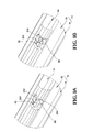
Fig. 9A is a perspective view to show that the first side of the first housing connected to the second embodiment of the first engaging member on the first body of the present invention; -
Fig. 9B is a perspective view to show that the first side of the first housing connected to the third embodiment of the first engaging member on the first body of the present invention; -
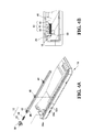
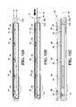
Fig. 10A shows that the first housing is connected to the body; -
Fig. 10B shows that a tool is inserted into the body to disassemble the first housing from the body, and -
Fig. 10C shows that the first housing is separated from the body by the inserted tool. -
Fig. 1 shows that the present invention comprises abody 10, an engagingassembly 12, afirst housing 14 and asecond housing 16. Thebody 10 comprises afirst body 18 and asecond body 20. -
Fig. 2 shows that thebody 10 comprises thefirst body 18 and thesecond body 20 which is firmly connected to thefirst body 18. Thefirst body 18 has atop portion 22a, abottom portion 24a, afirst side 26a and asecond side 28a which is located corresponding to thefirst side 26a. Thesecond body 20 is configured to be correspondent to thefirst body 18, and thesecond body 20 has atop portion 22b, abottom portion 24b, afirst side 26b and asecond side 28b which is located corresponding to thefirst side 26b. Thetop portion 22a of thefirst body 18 and thetop portion 22b of thesecond body 20 form thetop portion 22 of thebody 10. Thebottom portion 24a of thefirst body 18 and thebottom portion 24b of thesecond body 20 form thebottom portion 24 of thebody 10. Thefirst side 26a of thefirst body 18 and thefirst side 26b of thesecond body 20 form thefirst side 26 of thebody 10. Thesecond side 28a of thefirst body 18 and thesecond side 28b of thesecond body 20 form thesecond side 28 of thebody 10. The first andsecond sides second body 20 respectively have afirst release hole 30a and asecond release hole 30b for a tool to be inserted therein. -
Fig. 3 shows that thefirst side 26a of thefirst body 18 has afirst space 32a and at least onefirst connection part 33. Thefirst space 32a is substantially parallel to thefirst side 26a of thefirst body 18. Preferably, thefirst space 32a extends along the length of thefirst side 26a of thefirst body 18. Preferably, thefirst body 18 has multiplefirst connection parts 33. In one embodiment, thefirst connection part 33 is a hole. Thesecond side 28a of thefirst body 18 has asecond space 32b which is substantially parallel to thesecond side 28a of thefirst body 18. Preferably, thefirst side 26a of thefirst body 18 has afirst groove 34a and afirst passage 36a which is connected between thefirst space 32a and thefirst groove 34a. Preferably, thesecond side 28a of thefirst body 18 has asecond groove 34b and asecond passage 36b which is connected between thesecond space 32b and thesecond groove 34b. - The
first side 26b of thesecond body 20 has at least onefirst hole 38 which is located corresponding to thefirst space 32a of thefirst body 18. Thesecond side 28b of thesecond body 20 has at least onesecond connection part 40. Preferably, there are multiplefirst holes 38 and multiplesecond connection parts 40 arranged on thesecond body 20. In one embodiment, thesecond connection part 40 is a hole. - The engaging
assembly 12 comprises a first engagingmember 42 and a firstresilient member 44. The first engagingmember 42 is located between the first andsecond bodies member 42 has afirst end 43a, asecond end 43b which is located corresponding to thefirst end 43a, and at least one first engagingportion 46 which is located corresponding to thefirst hole 38 of thesecond body 20. The firstresilient member 44 is disposed between thefirst body 18 and the first engagingmember 42. Preferably, thefirst end 43a of the first engagingmember 42 has aprojection 48 which is located corresponding to the firstresilient member 44. It is noted that theprojection 48 is optionally used to assist the firstresilient member 44 to be disposed between thefirst body 18 and the first engagingmember 42. Thesecond end 43b of the first engagingmember 42 is located corresponding to thefirst release hole 30a. Preferably, a first fixingmember 50 is located corresponding to thefirst groove 34a of thefirst body 18. Preferably, the first engagingmember 42 has multiple firstengaging portions 46 located corresponding to the multiplefirst holes 38 of thesecond body 20. - In one preferable embodiment, the engaging
assembly 12 further has a second engagingmember 52 and a secondresilient member 54. The second engagingmember 52 is located corresponding to thesecond release hole 30b of thebody 10. The second engagingmember 52 has at least one second engagingportion 56 located in thesecond space 32b of thesecond side 28a of thefirst body 18. The secondresilient member 54 is located between thefirst body 18 and the second engagingmember 52. The second engagingmember 52 is kept at a pre-set position and located corresponding to thesecond release hole 30b of thesecond body 20 by the force of the secondresilient member 54 applied to the second engagingmember 52. Preferably, the second engagingmember 52 has multiple secondengaging portions 56. - As shown in
Figs. 4A and 4B , the first fixingmember 50 of the engagingassembly 12 is installed to thefirst groove 34a of thefirst side 26a of thefirst body 18, and the first engagingmember 42 is installed to thefirst space 32a of thefirst side 26a of thefirst body 18. The first fixingmember 50 has arecess 58 for receiving a portion of the firstresilient member 44. The firstresilient member 44 provides a force to the first engagingmember 42, and by the force, the first engagingmember 42 is kept at a pre-set position. - As shown in
Figs. 5A and 5B , the engagingassembly 12 has a second fixingmember 60 which is installed to thesecond groove 34b of thesecond side 28a of thefirst body 18. The second fixingmember 60 has arecess 62 for receiving a portion of the secondresilient member 54. Thesecond side 28a of thefirst body 18 has at least onesecond hole 64 which is located corresponding to the second engagingportion 56 of the second engagingmember 52. Preferably, there are multiplesecond holes 64 located in thesecond side 28a of thefirst body 18. In one embodiment, the multiple secondengaging portions 56 of the second engagingmember 52 are located corresponding to the multiplesecond holes 64 of thefirst body 18. The secondresilient member 54 provides a force to contact the second engagingmember 52, and by the force, the second engagingmember 52 is kept at a pre-set position. -
Fig. 6 shows that the engagingassembly 12 is installed between thefirst body 18 and thesecond body 20, in other words, the engagingassembly 12 is installed to thebody 10. More specifically, the first engagingportions 46 of the first engagingmember 42 of the engagingassembly 12 extend through thefirst holes 38 of thesecond body 20. Thefirst housing 14 is connected to thesecond body 20 and thesecond housing 16 is connected to thefirst body 18. In other words, thebody 10 is located between thefirst housing 14 and thesecond housing 16. Thefirst housing 14 has afirst side 66a and asecond side 66b, and the first andsecond sides second sides second body 20 respectively. Thefirst side 66a has at least onefirst contact portion 68 which is located corresponding to the first engagingportion 46 of the first engagingmember 42. Preferably, there are multiplefirst contact portions 68 located on thefirst housing 14. Thesecond side 66b of thefirst housing 14 has at least onefirst connection portion 70 which is located corresponding to thesecond connection part 40 of thesecond body 20. Preferably, thefirst housing 14 has multiplefirst connection portions 70. - The
second housing 16 has afirst side 72a and asecond side 72b, the first andsecond sides second sides first body 18 respectively. Thefirst side 72a of thesecond housing 16 has at least onesecond connection portion 74 which is located corresponding to thefirst connection part 33 of thefirst body 18. Preferably, thesecond housing 16 has multiplesecond connection portions 74. Thesecond side 72b of thesecond housing 16 has at least onesecond contact portion 76 which is located corresponding to the second engagingportion 56 of the second engagingmember 52. Preferably, thesecond housing 16 has multiplesecond contact portions 76. - As shown in
Figs. 7A and 7B , thefirst housing 14 has afirst connection portion 70 which is engaged with thesecond connection part 40 of thefirst housing 14. Preferably, thefirst connection portion 70 is a protrusion such as a latch. - As shown in
Figs. 8A, 8B and 8C , the first engagingmember 42 of the engagingassembly 12 is movably located in thefirst space 32a of thefirst body 18, and the first fixingmember 50 is located in thefirst groove 34a of thefirst body 18. The firstresilient member 44 is disposed between the first engagingmember 42 and the first fixingmember 50 so as to apply a force to the first engagingmember 42. More specifically, the first engagingportion 46 of the first engagingmember 42 is generally formed as a triangular part and has afirst guide face 78 and afirst contact face 80. Thefirst guide face 78 is located corresponding to thefirst contact portion 68 of thefirst housing 14. Preferably, thefirst guide face 78 is an inclined face. Thefirst contact face 80 is located corresponding to thefirst space 32a of thefirst body 18. When assembling, thefirst contact portion 68 of thefirst housing 14 is located corresponding to the first engagingportion 46 of the first engagingmember 42. When thefirst housing 14 is connected to thesecond body 20, thefirst connection portion 70 of thefirst housing 14 is connected to thesecond connection part 40 of thesecond body 20 as shown inFigs. 7A and 7B . Then, thefirst contact portion 68 of thefirst housing 14 is pushed to contact to the first engagingportion 46 of the first engagingmember 42. By the contact between thefirst guide face 78 of the first engagingportion 46 and thefirst contact portion 68 of thefirst housing 14, thefirst contact portion 68 of thefirst housing 14 moves thefirst guide face 78 of the first engagingportion 46 to push/compress the firstresilient member 44 until thefirst contact portion 68 of thefirst housing 14 moves over thefirst guide face 78 of the first engagingportion 46. Subsequently, the firstresilient member 44 releases the force to move the first engagingmember 42, so that thefirst contact face 80 of the first engagingportion 46 is engaged with thefirst contact portion 68 of thefirst housing 14 to secure the connection between thefirst housing 14 to thesecond body 20. In one embodiment, thefirst contact portion 68 of thefirst housing 14 has asecond guide face 82 and asecond contact face 84. Thesecond guide face 82 is an inclined face and located corresponding to thefirst guide face 78 of the first engagingportion 46 so as to guide the movement of the first engagingportion 46 of the first engagingmember 42 easily. Thesecond contact face 84 contacts thefirst contact face 80 of the first engagingportion 46. Preferably, one of thefirst contact face 80 of the at least one first engagingportion 46 and thesecond contact face 84 of the at least onefirst contact portion 68 is an inclined face. Preferably, afirst protrusion 86 extends from a portion of thefirst contact face 80 of thefirst contact portion 46, and thefirst protrusion 86 contacts thesecond contact face 84 of thefirst contact portion 68. Preferably, asecond protrusion 88 extends from a portion of thesecond contact face 84 of thefirst contact portion 68, and thesecond protrusion 88 contacts thefirst contact face 80 of the at least one first engagingportion 46. By the above-mentioned arrangement, thefirst housing 14 can be firmly connected to thesecond body 20. -
Fig. 9A shows the second embodiment of the first engagingportion 200 of the first engagingmember 42. The firstengaging portion 200 is generally formed as a rectangular body and has afirst guide face 202 and afirst contact face 204. Thefirst guide face 202 of the first engagingportion 200 of the first engagingmember 42 is one side of the rectangular body, and thefirst contact face 204 is a plane.Fig. 9B shows the third embodiment of the first engagingportion 300 of the first engagingmember 42. The firstengaging portion 300 of the first engagingmember 42 is generally formed as a cylindrical body and has afirst guide face 302. Thefirst guide face 302 of the first engagingportion 300 is a curved face of the cylindrical body. When thefirst housing 14 is connected to thesecond body 20, thefirst guide face 302 is pushed by thefirst contact portion 68 to move the first engagingmember 42. Thefirst guide face 302 is then moved by the firstresilient member 44 and contacts thefirst contact portion 68 again so as to firmly connect thefirst housing 14 to thesecond body 20. In other words, thefirst guide face 302 has the same function as thefirst contact face - It is noted that the
first guide face 78/202/302 of the first engagingportion 46/200/300 of the first engagingmember 42 can be configured to different shapes, such as a plane, an inclined face, a curved face and the combination thereof without departing the scope of the arrangement, among thesecond body 20, the first engagingmember 42 and thefirst housing 16, so as to easily guide the movement of the first engagingportion 46/200/300 of the first engagingmember 42 to engage with thefirst contact portion 68 of thefirst housing 14 and hence securely connect thefirst housing 14 to thesecond body 20. Similarly, the shapes of thesecond guide face 82 and the first and second contact faces 80 and 84 can be configured as a plane, an inclined face, a curved face and the combination thereof. - Referring to
Figs. 10A, 10B and 10C , whereinFig. 10A shows that thefirst housing 14 is connected to thesecond body 20. More specifically, the multiplefirst contact portions 68 of thefirst housing 14 are connected with the multiple firstengaging portions 46 of the first engagingmember 42, so that thefirst housing 14 is firmly connected to thesecond body 20. When thefirst housing 14 is to be disassembled from thesecond body 20, atool 90 such as thin and long stick is inserted into thefirst release hole 30a of thebody 10 and contacts thesecond end 43b of the first engagingmember 42 which is moved by thetool 90 to overcome the force of the firstresilient member 44 until the first engagingmember 42 is moved and the first engagingportions 46 are separated from thefirst contact portions 68 of the first housing 14 (asFig. 10B shown). Consequently, thefirst housing 14 can be disassembled from thesecond body 20, as shown inFig. 10C . - When the
tool 90 no longer pushes the first engagingmember 42, the firstresilient member 44 releases the force to the first engagingmember 42, so that the first engagingmember 42 is returned to its initial position. - It is noted that the
second housing 16 has the identical functions, mechanisms, and ways of operation with thefirst housing 14. That is to say, the way for mounting thesecond housing 16 to thefirst body 18 or disassembling thesecond housing 16 from thefirst body 18 is the same as the interaction between thefirst housing 14 and thesecond body 20. More specifically, thefirst connection part 33 of thefirst body 18, the second engageportion 56 of the second engagemember 52, and thesecond connection portion 74 and thesecond contact portion 76 of thesecond housing 16 can be respectively compared to thesecond connection part 40 of thesecond body 20, the first engageportion 46/200/300 of the first engagemember 42, and thefirst connection portion 70 and thefirst contact portion 68 of thefirst housing 14. The detailed description for assembling thesecond housing 16 to thefirst body 18 is therefore omitted. - While we have shown and described the embodiment in accordance with the present invention, it should be clear to those skilled in the art that further embodiments may be made without departing from the scope of the present invention.
Claims (15)
- A housing assembly for a portable electronic device, characterized in comprising: a first body (18) having a first side (26a) and a second side (28a) which is located corresponding to the first side (26a), the first side (26a) having a first space (32a), a second body (20) installed to the first body (18) and having a first release hole (30a) and at least one first hole (38) which is located corresponding to the first space (32a) of the first body (18), a first engaging member (42) movably located in the first space (32a) of the first body (18) and having at least one first engaging portion (46, 200, 300) which is located corresponding to the at least one first hole (38) of the second body (20), the first engaging member (42) located corresponding to the first release hole (30a) of the second body (20), a first resilient member (44) providing a force to the first engaging member (42) to orient the first engaging member (42) toward the first release hole (30a) of the second body (20), a first housing (14) connected to the second body (20) and having a first side (66a) and a second side (66b), the first side (66a) of the first housing (14) having at least one first contact portion (68) which is located corresponding to the at least one first engaging portion (46, 200, 300) of the first engaging member (42); when assembling, the at least one first contact portion (68) of the first housing (14) engaged with the at least one first engaging portion (46, 200, 300) of the first engaging member (42), the first housing (14) firmly connected to the second body (20) by the force of the first resilient member (44) applied to the first engaging member (42).
- The assembly as claimed in claim 1, wherein the first space (32a) is substantially parallel to the first side (26a) of the first body (18) and extends along a length of the first side (26a) of the first body (18).
- The assembly as claimed in claim 1 or 2, further comprising a first fixing member (50) which is disposed to the first body (18) and has a recess (58) in which the first resilient member (44) is partially received.
- The assembly as claimed in any one of claims 1-3, where the at least one first engaging portion (46, 200, 300) of the first engaging member (42) has a first contact face (80), and the at least one first contact portion (68) has a second contact face (84) which contacts the first contact face (80).
- The assembly as claimed in claim 4, wherein one of the first contact face (80) of the at least one first engaging portion (46, 200, 300) and the second contact face (84) of the at least one first contact portion (68) is an inclined face.
- The assembly as claimed in claim 5, further comprising a first protrusion (86) which extends from a portion of the first contact face (80) of the at least one first engaging portion (46, 200, 300) and contacts the second contact face (84) of the at least one first contact portion (68).
- The assembly as claimed in claim 5, further comprising a second protrusion (88) which extends from a portion of the second contact face (84) of the at least one first contact portion (68) and contacts the first contact face (80) of the at least one first engaging portion (46, 200, 300).
- The assembly as claimed in any one of claims 1-7, wherein the at least one first engaging portion (46, 200, 300) of the first engaging member (42) has a first guide face (78, 202, 302), and the at least one first contact portion (68) has a second guide face (82) which is located corresponding to the first guide face (78, 202, 302) so as to guide movement of the at least one first engaging portion (46, 200, 300) of the first engaging member (42).
- The assembly as claimed in claim 8, wherein one of the first and second guide faces (78, 82) is an inclined face.
- The assembly as claimed in claim 8, wherein the at least one first engaging portion (300) is a cylindrical body, and the first guide face (302) is a curved face.
- The assembly as claimed in claim 8, wherein the at least one first engaging portion (200) is a rectangular body, and the first guide face (202) is one side of the rectangular body.
- The assembly as claimed in any one of claims 1-11, wherein the first side (26a) of the first body (18) has at least one first connection part (33), the second side (28b) of the second body (20) has at least one second connection part (40), the second side (66b) of the first housing (14) has at least one first connection portion (70) which is engaged with the at least one second connection part (40) of the second body (20).
- The assembly as claimed in claim 12, further comprising a second housing (16) having a first side (72a) and a second side (72b), the first side (72a) of the second housing (16) having at least one second contact portion (76) which is located corresponding to the at least one first connection part (33) of the first body (18).
- The assembly as claimed in claim 1, wherein the first side (26a) of the first body (18) has at least one first connection part (33), the second side (28a) of the first body (18) has and at least one second hole (64), the second body (20) has a first side (26b) and a second side (28b), the first and second sides (26b, 28b) of the second body (20) are located corresponding to the first and second sides (26a, 28a) of the first body (18) respectively, the first side (26b) of the second body (20) provides the first release hole (30a) and the at least one first hole (38), the second side (28b) of the second body (20) has a second release hole (30b) and at least one second connection part (40), a second engaging member (52) is movably connected between the first and second bodies (18, 20), the second engaging member (52) is located corresponding to the second release hole (30b) of the second body (20), the second engaging member (52) has at least one second engaging portion (56) which is located corresponding to the at least one second hole (64) of the first body (18), a second resilient member (54) provides a force to the second engaging member (52) to keep the second engaging member (52) at a pre-set position, the second engaging member (52) is located corresponding to the second release hole (30b) of the second body (20), the second side (66b) of the first housing (14) has at least one first connection portion (70) which is located corresponding to the at least one second connection part (40) of the second body (20), a second housing (16) is connected to the first body (18) and has a first side (72a) and a second side (72b), the first side (72a) of the second housing (16) has at least one second connection portion (74) which is located corresponding to the at least one first connection part (33) of the first body (18), the second side (72b) of the second housing (16) has at least one second contact portion (76) which is located corresponding to the at least one second engaging portion (56) of the second engaging member (52); when the first housing (14) is connected to the second body (20), the at least one first connection portion (70) of the first housing (14) is engaged with the at least one second connection part (40) of the second body (20), the at least one first contact portion (68) of the first housing (14) is firmly engaged with the at least one first engaging portion (46, 200, 300) of the first engaging member (42) by the force of the first resilient member (44) applied to the first engaging member (42), so that the first housing (14) is securely connected to the second body (20); and when the second housing (16) is connected to the first body (18), the at least one second connection portion (74) of the second housing (16) is engaged with the at least one first connection part (33) of the first body (18), the at least one second contact portion (76) of the second housing (16) is firmly engaged with the at least one second engaging portion (56) of the second engaging member (52) by the force of the second resilient member (54) applied to the second engaging member (52), so that the second housing (16) is securely connected to the first body (18).
- The assembly as claimed in claim 14, wherein the at least one first engaging portion (46, 200, 300) of the first engaging member (42) has a first contact face (80), the at least one first contact portion (68) has a second contact face (84), a first protrusion (86) extends from a portion of the first contact face (80) of the at least one first engaging portion (46, 200, 300), the first protrusion (86) contacts the second contact face (84) of the at least one first contact portion (68), a second protrusion (88) extends from a portion of the second contact face (84) of the at least one first contact portion (68), the second protrusion (88) contacts the first contact face (80) of the at least one first engaging portion (46, 200, 300).
Priority Applications (1)
| Application Number | Priority Date | Filing Date | Title |
|---|---|---|---|
| EP13172972.5A EP2816784B1 (en) | 2013-06-20 | 2013-06-20 | Housing assembly for portable electronic device |
Applications Claiming Priority (1)
| Application Number | Priority Date | Filing Date | Title |
|---|---|---|---|
| EP13172972.5A EP2816784B1 (en) | 2013-06-20 | 2013-06-20 | Housing assembly for portable electronic device |
Publications (2)
| Publication Number | Publication Date |
|---|---|
| EP2816784A1 true EP2816784A1 (en) | 2014-12-24 |
| EP2816784B1 EP2816784B1 (en) | 2016-11-23 |
Family
ID=48628557
Family Applications (1)
| Application Number | Title | Priority Date | Filing Date |
|---|---|---|---|
| EP13172972.5A Active EP2816784B1 (en) | 2013-06-20 | 2013-06-20 | Housing assembly for portable electronic device |
Country Status (1)
| Country | Link |
|---|---|
| EP (1) | EP2816784B1 (en) |
Citations (3)
| Publication number | Priority date | Publication date | Assignee | Title |
|---|---|---|---|---|
| DE19618981C1 (en) * | 1996-05-10 | 1997-06-12 | Nokia Mobile Phones Ltd | Radio telephone handset |
| US20040203518A1 (en) * | 2002-06-28 | 2004-10-14 | Fei Zheng | Enclosure assembly for portable electronic device |
| US20120236518A1 (en) * | 2008-12-15 | 2012-09-20 | Nokia Corporation | Apparatus and method for use in assembly of a portable apparatus |
-
2013
- 2013-06-20 EP EP13172972.5A patent/EP2816784B1/en active Active
Patent Citations (3)
| Publication number | Priority date | Publication date | Assignee | Title |
|---|---|---|---|---|
| DE19618981C1 (en) * | 1996-05-10 | 1997-06-12 | Nokia Mobile Phones Ltd | Radio telephone handset |
| US20040203518A1 (en) * | 2002-06-28 | 2004-10-14 | Fei Zheng | Enclosure assembly for portable electronic device |
| US20120236518A1 (en) * | 2008-12-15 | 2012-09-20 | Nokia Corporation | Apparatus and method for use in assembly of a portable apparatus |
Also Published As
| Publication number | Publication date |
|---|---|
| EP2816784B1 (en) | 2016-11-23 |
Similar Documents
| Publication | Publication Date | Title |
|---|---|---|
| US9072163B2 (en) | Housing assembly for portable electronic device | |
| US9387647B2 (en) | Electronic device and dust cover thereof | |
| US9295178B1 (en) | Low profile compliant latch assembly and electronic circuit card and chassis incorporating same | |
| US20150017823A1 (en) | Connector | |
| US10881012B1 (en) | Anti-dismantle device | |
| US10014630B1 (en) | Card connector | |
| CN111261467A (en) | Silver graphite contact safety unit | |
| US8422211B2 (en) | Assembling/disassembling keyboard structure for a portable device | |
| EP2816784B1 (en) | Housing assembly for portable electronic device | |
| US7547856B2 (en) | Sealed pushbutton switch | |
| US9705122B2 (en) | Battery terminal with unintended deformation prevention features | |
| JP3182149U (en) | Partition with connecting member | |
| US8247720B2 (en) | Sealed pushbutton switch | |
| WO2011086595A1 (en) | Push button device | |
| JP5092365B2 (en) | Support foot mounting structure | |
| TWI535133B (en) | Pressing usb socket | |
| JP6213308B2 (en) | switch | |
| JP7004157B2 (en) | Switch device | |
| JP2020161679A (en) | Electronic component housing case | |
| JP3169054U (en) | Push switch | |
| TWI505070B (en) | Housing assembly for portable electronic device | |
| JP2006161997A (en) | Setting body and screw fixing member | |
| CN105098464B (en) | Push type USB socket | |
| JP2017188553A (en) | Enclosure | |
| JP6880644B2 (en) | Housing structure of electronic devices |
Legal Events
| Date | Code | Title | Description |
|---|---|---|---|
| PUAI | Public reference made under article 153(3) epc to a published international application that has entered the european phase |
Free format text: ORIGINAL CODE: 0009012 |
|
| 17P | Request for examination filed |
Effective date: 20140417 |
|
| AK | Designated contracting states |
Kind code of ref document: A1 Designated state(s): AL AT BE BG CH CY CZ DE DK EE ES FI FR GB GR HR HU IE IS IT LI LT LU LV MC MK MT NL NO PL PT RO RS SE SI SK SM TR |
|
| AX | Request for extension of the european patent |
Extension state: BA ME |
|
| GRAP | Despatch of communication of intention to grant a patent |
Free format text: ORIGINAL CODE: EPIDOSNIGR1 |
|
| INTG | Intention to grant announced |
Effective date: 20160617 |
|
| GRAS | Grant fee paid |
Free format text: ORIGINAL CODE: EPIDOSNIGR3 |
|
| GRAA | (expected) grant |
Free format text: ORIGINAL CODE: 0009210 |
|
| AK | Designated contracting states |
Kind code of ref document: B1 Designated state(s): AL AT BE BG CH CY CZ DE DK EE ES FI FR GB GR HR HU IE IS IT LI LT LU LV MC MK MT NL NO PL PT RO RS SE SI SK SM TR |
|
| REG | Reference to a national code |
Ref country code: GB Ref legal event code: FG4D |
|
| REG | Reference to a national code |
Ref country code: CH Ref legal event code: EP |
|
| REG | Reference to a national code |
Ref country code: IE Ref legal event code: FG4D |
|
| REG | Reference to a national code |
Ref country code: AT Ref legal event code: REF Ref document number: 848797 Country of ref document: AT Kind code of ref document: T Effective date: 20161215 |
|
| REG | Reference to a national code |
Ref country code: DE Ref legal event code: R096 Ref document number: 602013014319 Country of ref document: DE |
|
| PG25 | Lapsed in a contracting state [announced via postgrant information from national office to epo] |
Ref country code: LV Free format text: LAPSE BECAUSE OF FAILURE TO SUBMIT A TRANSLATION OF THE DESCRIPTION OR TO PAY THE FEE WITHIN THE PRESCRIBED TIME-LIMIT Effective date: 20161123 |
|
| REG | Reference to a national code |
Ref country code: LT Ref legal event code: MG4D |
|
| REG | Reference to a national code |
Ref country code: NL Ref legal event code: MP Effective date: 20161123 |
|
| REG | Reference to a national code |
Ref country code: AT Ref legal event code: MK05 Ref document number: 848797 Country of ref document: AT Kind code of ref document: T Effective date: 20161123 |
|
| PG25 | Lapsed in a contracting state [announced via postgrant information from national office to epo] |
Ref country code: GR Free format text: LAPSE BECAUSE OF FAILURE TO SUBMIT A TRANSLATION OF THE DESCRIPTION OR TO PAY THE FEE WITHIN THE PRESCRIBED TIME-LIMIT Effective date: 20170224 Ref country code: NL Free format text: LAPSE BECAUSE OF FAILURE TO SUBMIT A TRANSLATION OF THE DESCRIPTION OR TO PAY THE FEE WITHIN THE PRESCRIBED TIME-LIMIT Effective date: 20161123 Ref country code: LT Free format text: LAPSE BECAUSE OF FAILURE TO SUBMIT A TRANSLATION OF THE DESCRIPTION OR TO PAY THE FEE WITHIN THE PRESCRIBED TIME-LIMIT Effective date: 20161123 Ref country code: NO Free format text: LAPSE BECAUSE OF FAILURE TO SUBMIT A TRANSLATION OF THE DESCRIPTION OR TO PAY THE FEE WITHIN THE PRESCRIBED TIME-LIMIT Effective date: 20170223 Ref country code: SE Free format text: LAPSE BECAUSE OF FAILURE TO SUBMIT A TRANSLATION OF THE DESCRIPTION OR TO PAY THE FEE WITHIN THE PRESCRIBED TIME-LIMIT Effective date: 20161123 |
|
| PG25 | Lapsed in a contracting state [announced via postgrant information from national office to epo] |
Ref country code: AT Free format text: LAPSE BECAUSE OF FAILURE TO SUBMIT A TRANSLATION OF THE DESCRIPTION OR TO PAY THE FEE WITHIN THE PRESCRIBED TIME-LIMIT Effective date: 20161123 Ref country code: RS Free format text: LAPSE BECAUSE OF FAILURE TO SUBMIT A TRANSLATION OF THE DESCRIPTION OR TO PAY THE FEE WITHIN THE PRESCRIBED TIME-LIMIT Effective date: 20161123 Ref country code: FI Free format text: LAPSE BECAUSE OF FAILURE TO SUBMIT A TRANSLATION OF THE DESCRIPTION OR TO PAY THE FEE WITHIN THE PRESCRIBED TIME-LIMIT Effective date: 20161123 Ref country code: PL Free format text: LAPSE BECAUSE OF FAILURE TO SUBMIT A TRANSLATION OF THE DESCRIPTION OR TO PAY THE FEE WITHIN THE PRESCRIBED TIME-LIMIT Effective date: 20161123 Ref country code: HR Free format text: LAPSE BECAUSE OF FAILURE TO SUBMIT A TRANSLATION OF THE DESCRIPTION OR TO PAY THE FEE WITHIN THE PRESCRIBED TIME-LIMIT Effective date: 20161123 Ref country code: PT Free format text: LAPSE BECAUSE OF FAILURE TO SUBMIT A TRANSLATION OF THE DESCRIPTION OR TO PAY THE FEE WITHIN THE PRESCRIBED TIME-LIMIT Effective date: 20170323 Ref country code: ES Free format text: LAPSE BECAUSE OF FAILURE TO SUBMIT A TRANSLATION OF THE DESCRIPTION OR TO PAY THE FEE WITHIN THE PRESCRIBED TIME-LIMIT Effective date: 20161123 |
|
| PG25 | Lapsed in a contracting state [announced via postgrant information from national office to epo] |
Ref country code: EE Free format text: LAPSE BECAUSE OF FAILURE TO SUBMIT A TRANSLATION OF THE DESCRIPTION OR TO PAY THE FEE WITHIN THE PRESCRIBED TIME-LIMIT Effective date: 20161123 Ref country code: CZ Free format text: LAPSE BECAUSE OF FAILURE TO SUBMIT A TRANSLATION OF THE DESCRIPTION OR TO PAY THE FEE WITHIN THE PRESCRIBED TIME-LIMIT Effective date: 20161123 Ref country code: RO Free format text: LAPSE BECAUSE OF FAILURE TO SUBMIT A TRANSLATION OF THE DESCRIPTION OR TO PAY THE FEE WITHIN THE PRESCRIBED TIME-LIMIT Effective date: 20161123 Ref country code: DK Free format text: LAPSE BECAUSE OF FAILURE TO SUBMIT A TRANSLATION OF THE DESCRIPTION OR TO PAY THE FEE WITHIN THE PRESCRIBED TIME-LIMIT Effective date: 20161123 Ref country code: SK Free format text: LAPSE BECAUSE OF FAILURE TO SUBMIT A TRANSLATION OF THE DESCRIPTION OR TO PAY THE FEE WITHIN THE PRESCRIBED TIME-LIMIT Effective date: 20161123 |
|
| REG | Reference to a national code |
Ref country code: DE Ref legal event code: R097 Ref document number: 602013014319 Country of ref document: DE |
|
| PG25 | Lapsed in a contracting state [announced via postgrant information from national office to epo] |
Ref country code: IT Free format text: LAPSE BECAUSE OF FAILURE TO SUBMIT A TRANSLATION OF THE DESCRIPTION OR TO PAY THE FEE WITHIN THE PRESCRIBED TIME-LIMIT Effective date: 20161123 Ref country code: BG Free format text: LAPSE BECAUSE OF FAILURE TO SUBMIT A TRANSLATION OF THE DESCRIPTION OR TO PAY THE FEE WITHIN THE PRESCRIBED TIME-LIMIT Effective date: 20170223 Ref country code: BE Free format text: LAPSE BECAUSE OF FAILURE TO SUBMIT A TRANSLATION OF THE DESCRIPTION OR TO PAY THE FEE WITHIN THE PRESCRIBED TIME-LIMIT Effective date: 20161123 Ref country code: SM Free format text: LAPSE BECAUSE OF FAILURE TO SUBMIT A TRANSLATION OF THE DESCRIPTION OR TO PAY THE FEE WITHIN THE PRESCRIBED TIME-LIMIT Effective date: 20161123 |
|
| PLBE | No opposition filed within time limit |
Free format text: ORIGINAL CODE: 0009261 |
|
| STAA | Information on the status of an ep patent application or granted ep patent |
Free format text: STATUS: NO OPPOSITION FILED WITHIN TIME LIMIT |
|
| 26N | No opposition filed |
Effective date: 20170824 |
|
| PG25 | Lapsed in a contracting state [announced via postgrant information from national office to epo] |
Ref country code: SI Free format text: LAPSE BECAUSE OF FAILURE TO SUBMIT A TRANSLATION OF THE DESCRIPTION OR TO PAY THE FEE WITHIN THE PRESCRIBED TIME-LIMIT Effective date: 20161123 |
|
| PG25 | Lapsed in a contracting state [announced via postgrant information from national office to epo] |
Ref country code: MC Free format text: LAPSE BECAUSE OF FAILURE TO SUBMIT A TRANSLATION OF THE DESCRIPTION OR TO PAY THE FEE WITHIN THE PRESCRIBED TIME-LIMIT Effective date: 20161123 |
|
| REG | Reference to a national code |
Ref country code: CH Ref legal event code: PL |
|
| REG | Reference to a national code |
Ref country code: IE Ref legal event code: MM4A |
|
| REG | Reference to a national code |
Ref country code: FR Ref legal event code: ST Effective date: 20180228 |
|
| PG25 | Lapsed in a contracting state [announced via postgrant information from national office to epo] |
Ref country code: IE Free format text: LAPSE BECAUSE OF NON-PAYMENT OF DUE FEES Effective date: 20170620 Ref country code: CH Free format text: LAPSE BECAUSE OF NON-PAYMENT OF DUE FEES Effective date: 20170630 Ref country code: LU Free format text: LAPSE BECAUSE OF NON-PAYMENT OF DUE FEES Effective date: 20170620 Ref country code: LI Free format text: LAPSE BECAUSE OF NON-PAYMENT OF DUE FEES Effective date: 20170630 |
|
| PG25 | Lapsed in a contracting state [announced via postgrant information from national office to epo] |
Ref country code: FR Free format text: LAPSE BECAUSE OF NON-PAYMENT OF DUE FEES Effective date: 20170630 |
|
| PG25 | Lapsed in a contracting state [announced via postgrant information from national office to epo] |
Ref country code: MT Free format text: LAPSE BECAUSE OF NON-PAYMENT OF DUE FEES Effective date: 20170620 |
|
| PG25 | Lapsed in a contracting state [announced via postgrant information from national office to epo] |
Ref country code: HU Free format text: LAPSE BECAUSE OF FAILURE TO SUBMIT A TRANSLATION OF THE DESCRIPTION OR TO PAY THE FEE WITHIN THE PRESCRIBED TIME-LIMIT; INVALID AB INITIO Effective date: 20130620 |
|
| PG25 | Lapsed in a contracting state [announced via postgrant information from national office to epo] |
Ref country code: CY Free format text: LAPSE BECAUSE OF FAILURE TO SUBMIT A TRANSLATION OF THE DESCRIPTION OR TO PAY THE FEE WITHIN THE PRESCRIBED TIME-LIMIT Effective date: 20161123 |
|
| PG25 | Lapsed in a contracting state [announced via postgrant information from national office to epo] |
Ref country code: MK Free format text: LAPSE BECAUSE OF FAILURE TO SUBMIT A TRANSLATION OF THE DESCRIPTION OR TO PAY THE FEE WITHIN THE PRESCRIBED TIME-LIMIT Effective date: 20161123 |
|
| PG25 | Lapsed in a contracting state [announced via postgrant information from national office to epo] |
Ref country code: TR Free format text: LAPSE BECAUSE OF FAILURE TO SUBMIT A TRANSLATION OF THE DESCRIPTION OR TO PAY THE FEE WITHIN THE PRESCRIBED TIME-LIMIT Effective date: 20161123 |
|
| PG25 | Lapsed in a contracting state [announced via postgrant information from national office to epo] |
Ref country code: AL Free format text: LAPSE BECAUSE OF FAILURE TO SUBMIT A TRANSLATION OF THE DESCRIPTION OR TO PAY THE FEE WITHIN THE PRESCRIBED TIME-LIMIT Effective date: 20161123 Ref country code: IS Free format text: LAPSE BECAUSE OF FAILURE TO SUBMIT A TRANSLATION OF THE DESCRIPTION OR TO PAY THE FEE WITHIN THE PRESCRIBED TIME-LIMIT Effective date: 20170323 |
|
| PGFP | Annual fee paid to national office [announced via postgrant information from national office to epo] |
Ref country code: DE Payment date: 20250410 Year of fee payment: 13 |
|
| PGFP | Annual fee paid to national office [announced via postgrant information from national office to epo] |
Ref country code: GB Payment date: 20250408 Year of fee payment: 13 |