EP2816349A1 - Orientation independent meter - Google Patents
Orientation independent meter Download PDFInfo
- Publication number
- EP2816349A1 EP2816349A1 EP14173154.7A EP14173154A EP2816349A1 EP 2816349 A1 EP2816349 A1 EP 2816349A1 EP 14173154 A EP14173154 A EP 14173154A EP 2816349 A1 EP2816349 A1 EP 2816349A1
- Authority
- EP
- European Patent Office
- Prior art keywords
- test strip
- orientation
- sample
- analyte
- contact
- Prior art date
- Legal status (The legal status is an assumption and is not a legal conclusion. Google has not performed a legal analysis and makes no representation as to the accuracy of the status listed.)
- Granted
Links
Images





Classifications
-
- G—PHYSICS
- G01—MEASURING; TESTING
- G01N—INVESTIGATING OR ANALYSING MATERIALS BY DETERMINING THEIR CHEMICAL OR PHYSICAL PROPERTIES
- G01N27/00—Investigating or analysing materials by the use of electric, electrochemical, or magnetic means
- G01N27/26—Investigating or analysing materials by the use of electric, electrochemical, or magnetic means by investigating electrochemical variables; by using electrolysis or electrophoresis
- G01N27/28—Electrolytic cell components
- G01N27/30—Electrodes, e.g. test electrodes; Half-cells
- G01N27/327—Biochemical electrodes, e.g. electrical or mechanical details for in vitro measurements
- G01N27/3271—Amperometric enzyme electrodes for analytes in body fluids, e.g. glucose in blood
- G01N27/3272—Test elements therefor, i.e. disposable laminated substrates with electrodes, reagent and channels
-
- G—PHYSICS
- G01—MEASURING; TESTING
- G01N—INVESTIGATING OR ANALYSING MATERIALS BY DETERMINING THEIR CHEMICAL OR PHYSICAL PROPERTIES
- G01N27/00—Investigating or analysing materials by the use of electric, electrochemical, or magnetic means
- G01N27/26—Investigating or analysing materials by the use of electric, electrochemical, or magnetic means by investigating electrochemical variables; by using electrolysis or electrophoresis
- G01N27/28—Electrolytic cell components
- G01N27/30—Electrodes, e.g. test electrodes; Half-cells
- G01N27/327—Biochemical electrodes, e.g. electrical or mechanical details for in vitro measurements
- G01N27/3271—Amperometric enzyme electrodes for analytes in body fluids, e.g. glucose in blood
- G01N27/3273—Devices therefor, e.g. test element readers, circuitry
Definitions
- This application generally relates to the field of blood analyte measurement systems and more specifically to portable analyte meters that are configured to detect an orientation of a test strip inserted therein and to correctly adjust a test signal applied thereto in response to the detected orientation.
- Blood glucose measurement systems typically comprise an analyte meter that is configured to receive a biosensor, usually in the form of a test strip. Because many of these systems are portable, and testing can be completed in a short amount of time, patients are able to use such devices in the normal course of their daily lives without significant interruption to their personal routines.
- a person with diabetes may measure their blood glucose levels several times a day as a part of a self management process to ensure glycemic control of their blood glucose within a target range.
- a failure to maintain target glycemic control can result in serious diabetes-related complications including cardiovascular disease, kidney disease, nerve damage and blindness.
- patient or “user” refer to any human or animal subject and are not intended to limit the systems or methods to human use, although use of the subject invention in a human patient represents a preferred embodiment.
- sample means a volume of a liquid, solution or suspension, intended to be subjected to qualitative or quantitative determination of any of its properties, such as the presence or absence of a component, the concentration of a component, e.g., an analyte, etc.
- the embodiments of the present invention are applicable to human and animal samples of whole blood. Typical samples in the context of the present invention as described herein include blood, plasma, red blood cells, serum and suspensions thereof.
- FIG. 1A illustrates an analyte measurement system 100 that includes an analyte meter 10.
- the analyte meter 10 is defined by a housing 11 that retains a data management unit ("DMU") 140 and further includes a port 22 sized for receiving a biosensor.
- the analyte meter 10 may be a hand held blood glucose meter and the biosensor is provided in the form of a test strip 24 inserted into test strip port 22 for performing blood glucose measurements.
- the analyte meter 10 further includes a plurality of user interface buttons 16, and a display 14 as illustrated in FIG. 1A .
- a predetermined number of glucose test strips may be stored in the housing 11 and made accessible for use in blood glucose testing.
- the plurality of user interface buttons 16 are associated with the DMU 140 and can be configured to allow the entry of data, to prompt an output of data, to navigate menus presented on the display 14, and to execute commands.
- Output data can include values representative of analyte concentration presented on the display 14.
- Input information may include information related to the everyday lifestyle of an individual, such as food intake, medication use, occurrence of health check-ups, and general health condition and exercise levels of an individual. These inputs can be requested via prompts presented on the display 14 and can be stored in a memory module of the analyte meter 10.
- the user interface buttons 16 include markings, e.g., up-down arrows, text characters "OK", etc, which allow a user to navigate through the user interface presented on the display 14.
- the buttons 16 are shown herein as separate switches, a touch screen interface on display 14 with virtual buttons may also be utilized.
- the electronic components of the analyte measurement system 100 can be disposed on, for example, a printed circuit board situated within the housing 11 and forming the DMU 140 of the herein described system.
- FIG. 1B illustrates, in simplified schematic form, several of the electronic subsystems disposed within the housing 11 for purposes of this embodiment.
- the DMU 140 includes a processing unit 122 in the form of a microprocessor, a microcontroller, an application specific integrated circuit ("ASIC"), a mixed signal processor (“MSP”), a field programmable gate array (“FPGA”), or a combination thereof, and is electrically connected to various electronic modules included on, or connected to, the printed circuit board, as will be described below.
- ASIC application specific integrated circuit
- MSP mixed signal processor
- FPGA field programmable gate array
- the processing unit 122 is electrically connected to, for example, a test strip port connector 104 ("SPC") via an analog front end (AFE) subsystem 125.
- the AFE 125 is electrically connected to the strip port connector 104 during blood glucose testing.
- the AFE 125 detects a resistance magnitude change across electrodes of analyte test strip 24 which indicates that a blood sample has been applied thereto, using a potentiostat.
- a preset voltage waveform is applied across the sample via the electrodes which generates a an electric current therethrough.
- the AFE 125 converts the electric current measurement into digital form for presentation on the display 14.
- the processing unit 122 can be configured to receive input from the strip port connector 104, analog front end subsystem 125, and may also perform a portion of the potentiostat function and the current measurement function.
- the analyte test strip 24 can be in the form of an electrochemical glucose test strip, of which various embodiments are described below.
- the test strip 24 is defined by a nonporous substrate that can include one or more working electrodes.
- Test strip 24 can also include a plurality of electrical contact pads, where each electrode can be in electrical communication with at least one electrical contact pad, as described below in relation to FIGs. 2A - 9C .
- Strip port connector 104 can be configured to electrically interface to the electrical contact pads, using electrical contacts in the form of prongs, and form electrical communication with the electrodes.
- Test strip 24 can include a reagent layer that is disposed over one or more electrodes within the test strip 24, such as a working electrode.
- the reagent layer can include an enzyme and a mediator.
- Exemplary enzymes suitable for use in the reagent layer include glucose oxidase, glucose dehydrogenase (with pyrroloquinoline quinone co-factor, "PQQ”), and glucose dehydrogenase (with flavin adenine dinucleotide co-factor, "FAD”).
- An exemplary mediator suitable for use in the reagent layer includes ferricyanide, which in this case is in the oxidized form.
- the reagent layer can be configured to physically transform glucose in the applied sample into an enzymatic by-product and in the process generate an amount of reduced mediator (e.g., ferrocyanide) that is proportional to the glucose concentration of the sample.
- the working electrode can then be used to apply the preset voltage waveform to the sample and to measure a concentration of the reduced mediator in the form of an electric current.
- microcontroller 122 can convert the current magnitude into a glucose concentration for presentation on the display 14.
- a display module 119 which may include a display processor and display buffer, is electrically connected to the processing unit 122 over the electrical interface 123 for receiving and displaying output data, and for displaying user interface input options under control of processing unit 122.
- the structure of the user interface, such as menu options, is stored in user interface module 103 and is accessible by processing unit 122 for presenting menu options to a user of the blood glucose measurement system 100.
- An audio module 120 includes a speaker 121 for outputting audio data received or stored by the DMU 140. Audio outputs can include, for example, notifications, reminders, and alarms, or may include audio data to be replayed in conjunction with display data presented on the display 14. Such stored audio data can be accessed by processing unit 122 and executed as playback data at appropriate times.
- a volume of the audio output is controlled by the processing unit 122, and the volume setting can be stored in settings module 105, as determined by the processor or as adjusted by the user.
- User input module 102 receives inputs via user interface buttons 16 which are processed and transmitted to the processing unit 122 over the electrical interface 123.
- the processing unit 122 may have electrical access to a digital time-of-day clock connected to the printed circuit board for recording dates and times of blood glucose measurements, which may then be accessed, uploaded, or displayed at a later time as necessary.
- the display 14 can alternatively include a backlight whose brightness may be controlled by the processing unit 122 via a light source control module 115.
- the user interface buttons 16 may also be illuminated using LED light sources electrically connected to processing unit 122 for controlling a light output of the buttons.
- the light source module 115 is electrically connected to the display backlight and processing unit 122. Default brightness settings of all light sources, as well as settings adjusted by the user, are stored in a settings module 105, which is accessible and adjustable by the processing unit 122.
- a memory module 101 that includes but are not limited to volatile random access memory (“RAM”) 112, a non-volatile memory 113, which may comprise read only memory (“ROM”) or flash memory, and a circuit 114 for connecting to an external portable memory device, for example, via a USB data port, is electrically connected to the processing unit 122 over a electrical interface 123.
- External memory devices may include flash memory devices housed in thumb drives, portable hard disk drives, data cards, or any other form of electronic storage devices.
- the on-board memory can include various embedded applications and stored algorithms in the form of programs executed by the processing unit 122 for operation of the analyte meter 10, as will be explained below.
- On board memory can also be used to store a history of a user's blood glucose measurements including dates and times associated therewith. Using the wireless transmission capability of the analyte meter 10 or the data port 13, as described below, such measurement data can be transferred via wired or wireless transmission to connected computers or other processing devices.
- a wireless module 106 may include transceiver circuits for wireless digital data transmission and reception via one or more internal digital antennas 107, and is electrically connected to the processing unit 122 over electrical interface 123.
- the wireless transceiver circuits may be in the form of integrated circuit chips, chipsets, programmable functions operable via processing unit 122, or a combination thereof.
- Each of the wireless transceiver circuits is compatible with a different wireless transmission standard.
- a wireless transceiver circuit 108 may be compatible with the Wireless Local Area Network IEEE 802.11 standard known as WiFi.
- Transceiver circuit 108 may be configured to detect a WiFi access point in proximity to the analyte meter 10 and to transmit and receive data from such a detected WiFi access point.
- a wireless transceiver circuit 109 may be compatible with the Bluetooth protocol and is configured to detect and process data transmitted from a Bluetooth beacon in proximity to the analyte meter 10.
- a wireless transceiver circuit 110 may be compatible with the near field communication ("NFC") standard and is configured to establish radio communication with, for example, another NFC compliant device in proximity to the analyte meter 10.
- a wireless transceiver circuit 111 may comprise a circuit for cellular communication with cellular networks and is configured to detect and link to available cellular communication towers.
- a power supply module 116 is electrically connected to all modules in the housing 11 and to the processing unit 122 to supply electric power thereto.
- the power supply module 116 may comprise standard or rechargeable batteries 118 or an AC power supply 117 may be activated when the analyte meter 10 is connected to a source of AC power.
- the power supply module 116 is also electrically connected to processing unit 122 over the electrical interface 123 for supplying power thereto and so that processing unit 122 can monitor a power level remaining in a battery power mode of the power supply module 116.
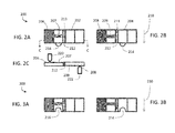
- FIGs. 2A-9C illustrate embodiments of a substantially flat (planar), elongated test strip 200 and strip port connector 104 that may be used for analyte measurement when the test strip 200 is inserted into a test strip port 22 of the analyte meter 100 in either of at least two orientations.
- a test strip 200 is defined by opposing sides herein referred to as a top side 202 and a bottom side 204 of the test strip 200. Referring specifically to FIG.
- test strip 200 having conductive contact pads 206, 208 disposed at opposite ends of the test strip 200, and in which contact pad 206 is provided on the top side 202 and contact pad 208 is provided on the bottom side 204 of the test strip 200.
- An arrow 210 indicates the direction of insertion of the test strip 200 into the test strip port 22, which may be inserted with either side 202, 204 of the test strip 200 facing upwardly.
- the test strip 200 includes a sample chamber 212 for receiving a sample therein provided by a user at one end 213 of the sample chamber 212.
- Electrodes 207, 209 extend from each contact pad 206, 208, respectively, to the sample chamber 212 wherein the sample provided therein makes physical contact with the electrodes 207, 209 and thereby establishes an electrical communication path between the contact pads 206, 208 on opposite ends and opposite sides 202, 204, of the test strip 200.
- the analyte meter 100 that receives the test strip 200 in its test strip port 22 uses strip port connector 104 to make an electrical connection with the pair of the contact pads 206, 208 using contacts, such as prongs, 220, 222, respectively, that engage the contact pads 206, 208, of the test strip 200.
- One of the prongs 222 is disposed to contact the bottom side contact pad 208 while another prong 220 is configured to electrically connect with the top side contact pad 206 when the test strip 200 is inserted into the test strip port 22 in the first orientation.
- the prong 222 electrically connects with the top side contact pad 206 and the prong 220 electrically connects with the bottom side contact pad 208.
- FIGs. 2A-C depict a test strip 200 whose orientation (i.e., first orientation or second orientation) is detected upon insertion into the test strip port 22 of the analyte meter 100.
- a projection, or lug, 214 disposed along a longitudinal edge of the test strip 200 may be sensed by the analyte meter 100 to determine the orientation of the test strip, for example, determining whether the top contact pad 206 faces upward or the bottom contact pad 208 faces upward, indicative of the first orientation and the second orientation, respectively.
- the first orientation i.e., the top contact pad 206 facing upward, may be referred to herein as the default orientation.
- the projection 214 may work in conjunction with a deflectable conductive element in the analyte meter, such as a conductive switch, that transmits a signal upon being deflected by the projection 214 when the test strip 200 is inserted in the test strip port 22 in one orientation, e.g., "top side up", and is not deflected if the test strip 200 is inserted into the test strip port 22 in a second orientation, e.g., "bottom side up”.
- a sensing device such as a mechanical microswitch, photodiode, capacitance sensor, or any other kind of detector may be used to detect the presence or absence of the projection 214. FIGs.
- 3A-B illustrate a test strip 300 that is similar in all respects to the test strip 200 just described with reference to FIGs. 2A-C , except that the projection 214 of the test strip 200 is replaced with an indentation 216 in the test strip 300.
- the indentation 216 may be used to detect an orientation of the test strip 300 at the time of its insertion into the analyte meter 100, in the direction indicated by arrow 210, such as by using any of the sensing devices identified above that detects the presence or absence of the indentation 216 of the test strip 300 at the time of insertion of the test strip 300 or, as described above with respect to the projection 214, a conductive deflectable element in the test strip port 22 of the analyte meter 100, such as a conductive switch, may be used to detect the indentation 216 wherein the indentation 216 positioned over the deflectable element fails to deflect it.
- FIGs. 4A-E illustrate another embodiment of a substantially flat (planar), elongated test strip 400 and strip port connector 104 that may be used for analyte measurement when the test strip 400 is inserted into a test strip port 22 of the analyte meter 100 in either of at least two orientations.
- a test strip 400 is defined by opposing sides herein referred to as a top side 402 and a bottom side 404 of the test strip 400. Referring specifically to FIG.
- test strip 400 having conductive contact pads 406 and 428 at one end of the test strip 400, and contact pads 408 and 426 at an opposite end of the test strip 400, and in which contact pads 406 and 426 are provided on the top side 402, and contact pads 408 and 428 are provided on the bottom side 404 of the test strip 400.
- An arrow 210 indicates the direction of insertion of the test strip 400 into the test strip port 22, which may be inserted with either side 402, 404 of the test strip 400 facing upwardly.
- the test strip 400 includes a sample chamber 412 for receiving a sample therein provided by a user at one end 413 of the sample chamber 412.
- Electrodes 407, 427, 409, 429 extend from each contact pad 406, 426, 408, 428, respectively, to the sample chamber 412 wherein the sample provided therein makes physical contact with the electrodes 407, 427, 409, 429 and thereby establishes an electrical communication path between the contact pads 406, 408, 426, 428 on opposite ends and opposite sides 402, 404, of the test strip 400.
- the analyte meter 100 that receives the test strip 400 in its test strip port 22 may use strip port connector 104 to make an electrical connection with a pair of the contact pads, 406 and 426, or 408 and 428, using a strip port connector having at least one pair of electrical contacts, herein referred to as prongs, 420, 424 ( FIG. 4C ), that engage the corresponding pair of contact pads 406-426 or 408-428 on the same side 402, 404, respectively, of the test strip 400, depending on the orientation of the test strip 400 in the test strip port 22.
- the prongs 420, 424 are shown facing downward, but may also face upward to connect with the same pairs of contact pads 406-426 or 408-428 in the manner described herein.
- the analyte meter 100 that receives the test strip 400 in its test strip port 22 may use strip port connector 104 to make an electrical connection with the contact pads, 406, 426, 408, and 428, using a strip port connector having at least two sets of electrical contacts, herein referred to as prongs, 420, 424, and 421, 425, ( FIG. 4D ), that engage the corresponding pairs of contact pads 406-426 and 408-428 on the sides 402, 404, respectively, of the test strip 400, when the test strip 400 is inserted in a first (default) orientation in the test strip port 22.
- strip port connector 104 may use strip port connector 104 to make an electrical connection with the contact pads, 406, 426, 408, and 428, using a strip port connector having at least two sets of electrical contacts, herein referred to as prongs, 420, 424, and 421, 425, ( FIG. 4D ), that engage the corresponding pairs of contact pads 406-426 and 408-428 on the sides 402, 404,
- the test strip 400 may be inserted in a second orientation, in the manner described herein, wherein prongs, 420, 424, and 421, 425, engage the corresponding pairs of contact pads 408-428 and 426-406 on the sides 404, 402, respectively, of the test strip 400.
- FIG. 4E illustrates an end view of an embodiment of the two sets of prongs, 420, 424, and 421, 425, wherein upper prong 424 and lower prong 425 are visible in the perspective of FIG. 4E while upper prong 420 and lower prong 421 are similarly structured and positioned behind prongs 424, 425, respectively, in the view of FIG. 4E .
- the prongs, 420, 424, 421, and 425 comprise flexible spring arms, of which spring arms 410, 411 corresponding to prongs 424, 425, respectively, are visible in the perspective of FIG. 4 .
- Such prongs may be fabricated from a conductive metallic material which flex in a direction away from the test strip 400 when the test strip is inserted therebetween by a user in the direction indicated by arrow 210.
- the prongs 424, 425 may be electrically shorted together by an optional electrical connector 423, as well as prongs 420, 421, by a corresponding electrical connector, thereby forming a single circuit node therewith of common voltage.
- the flexible spring arms 410, 411 provide enough compressive force to make electrical contact with contact pads 426, 408, respectively, (as well as spring arms corresponding to prongs 420, 421 making electrical contact with contact pads 406, 428, respectively) and to secure the test strip 400 therebetween when the test strip is inserted and when an analyte measurement process is undertaken by the meter 100, as described herein.
- FIGs. 4A-E depict a system wherein an orientation of test strip 400 (i.e., first orientation or second orientation) is detected upon insertion into the test strip port 22 of the analyte meter 100.
- a projection, or lug, 414 disposed along a longitudinal edge of the test strip 400 may be sensed by the analyte meter 100 to determine the orientation of the test strip, for example, determining whether the top contact pads 406, 426 face upward or the bottom contact pads 408, 428 face upward, indicative of the first and second orientations, respectively.
- the first orientation i.e., the top contact pads 406, 426 facing upward, may be referred to herein as the default orientation.
- the projection 414 may work in conjunction with a sensing element 415 in the analyte meter, such as a conductive switch, that transmits a signal upon being deflected by the projection 414 when the test strip 400 is inserted in the test strip port 22 in one orientation, e.g., "top side up” and is not deflected if the test strip 400 is inserted into the test strip port 22 in a second orientation, e.g., "bottom side up”.
- the sensing device 415 may be embodied as a mechanical microswitch, a deflectable conductive element, a photodiode, a capacitance sensor, or any other suitable detector to detect the presence or absence of the projection 414.
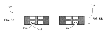
- FIGs. 5A-B illustrate a test strip 500 that is similar in all respects to the test strip 400 just described with reference to FIGs. 4A-E , except that the projection 414 of the test strip 400 is replaced with an indentation 416 in the test strip 500.
- the indentation 416 may be used to detect an orientation of the test strip 500 at the time of its insertion into the analyte meter 100, in the direction indicated by arrow 210, for example, using a sensing device 415, such as a mechanical microswitch, photodiode, capacitance sensor, or any other kind of detector that senses the presence or absence of the indentation 416 of the test strip 500 or, as described above with respect to the projection 414, a deflectable element in the test strip port 22 of the analyte meter 100 may be used to detect the indentation 416 wherein the indentation 416 positioned over the deflectable element fails to deflect it.
- a sensing device 415 such as a mechanical microswitch, photodiode, capacitance sensor, or any other kind of detector that senses the presence or absence of the indentation 416 of the test strip 500 or, as described above with respect to the projection 414, a deflectable element in the test strip port 22 of the
- a projection 414 and an indentation 416 have been described as exemplary physical features that may be used to detect an orientation of a test strip 24, such examples should not be interpreted as limiting the embodiments described herein.
- Other detectable physical features may be formed or fabricated in the test strip 24 without departing from the spirit of the embodiments described herein.
- a magnetic strip or indicator in the test strip 24 may be detected by a magnetic relay in the test strip port 22.
- rotationally variant or invariant optical features may be printed or embedded in the test strip 24 which may be detected by optical readers, such as 1D or 2D barcode scanners, or an optical pattern matching system in the analyte meter 100, as a further example.
- the various mechanisms and methods described herein to determine test strip 24 orientation may be used in combination, which may serve as a verification of a determined test strip 24 orientation.
- FIGs. 6A-C illustrate another embodiment of a substantially flat (planar), elongated test strip 600 and strip port connector 104 that may be used for analyte measurement when the test strip 600 is inserted into a test strip port 22 of the analyte meter 100 in either of at least two orientations.
- the test strip 600 is defined by opposing sides herein referred to as a top side 602 and a bottom side 604 of the test strip 600.
- the test strip 600 having conductive contact pads 606, 608 disposed at opposite ends of the test strip 600, and in which contact pad 606 is provided on the top side 602 and contact pad 208 is provided on the bottom side 604 of the test strip 600.
- An arrow 210 indicates the direction of insertion of the test strip 600 into the test strip port 22, which may be inserted with either side 602, 604 of the test strip 600 facing upwardly.
- the test strip 600 includes a sample chamber 612 for receiving a sample therein provided by a user at one end 613 of the sample chamber 612. Electrodes 607, 609 extend from each contact pad 606, 608, respectively, to the sample chamber 612 wherein the sample provided therein makes physical contact with the electrodes 607, 609 and thereby establishes an electrical communication path between the contact pads 606, 608 on opposite ends and opposite sides 602, 604, of the test strip 600.
- One of the contact pads 606 comprises a border 605 that is non-conductive.
- This border 605 may be formed by ablation of the conductive material of the contact pad 606, such as using laser ablation, or, in another embodiment, the region surrounded by the non-conducive border 605 could be entirely formed as a non-conductive patch.
- the analyte meter 100 into which the test strip is inserted comprises two prongs 620, 621, proximate one end of the test strip 600, wherein one prong 620 is used for electrically contacting the region of the contact pad 606 within the border 605 and the other prong 621 for contacting the region of the contact pad 606 outside the border 605, when the top side 602 of the test strip is facing upward, as indicated by the contact points 614.
- a resistance between these two prongs 620, 621 of the analyte meter 100 can be measured while the prongs 620, 621 are physically simultaneously touching the region within the border 605 and the region outside the border 605 of contact pad 606, respectively.
- a high resistance will be measured because there is no conductive path between the prongs 620, 621 when they are touching contact points 614, thereby indicating the orientation of the test strip 600 as being "top side up".
- a first orientation of the test strip 600 may be determined based on the high resistance, and may be referred to herein as the default orientation.
- the two prongs 620, 621, proximate one end of the test strip 600 may electrically connect to the contact pad 608 when the test strip 600 is inserted into the test strip port with the bottom side 604 facing upward ( FIG. 6B ) as indicated by the contact points 615.
- a resistance between the prongs 620, 621 of the analyte meter 100 can be measured while the prongs 620, 621 are physically simultaneously touching contact pad 608.
- a low resistance will be measured because contact pad 608 is entirely conductive, thereby indicating the orientation of the test strip 600 as being "bottom side up”.
- a second orientation of the test strip 600 may be determined based on the low measured resistance. Based on these measured resistances using two prongs 620, 621 proximate one end of the test strip 600, analyte meter 100 may determine in which orientation the test strip 600 has been inserted.
- the analyte meter 100 that receives the test strip 600 in its test strip port 22 uses strip port connector 104 to make an electrical connection with the contact pads 606, 608 using a strip port connector having at least one pair of electrical contacts, herein referred to as prongs, 621, 622, respectively, that engage the contact pads 606, 608, of the test strip 600.
- One of the prongs 622 is disposed to contact the bottom side contact pad 608 while another prong 621 is configured to electrically connect with the top side contact pad 606 when the test strip is inserted into the test strip port 22 in the first orientation.
- the prong 622 electrically connects with the top side contact pad 606 and the prong 621 electrically connects with the bottom side contact pad 608.
- FIGs. 7A-C illustrate another embodiment of a substantially flat (planar), elongated test strip 700 and strip port connector 104 that may be used for analyte measurement when the test strip 700 is inserted into a test strip port 22 of the analyte meter 100 in either of at least two orientations.
- a test strip 700 is defined by opposing sides herein referred to as a top side 702 and a bottom side 704 of the test strip 700. Referring specifically to FIG.
- test strip 700 having conductive contact pads 706 and 728 at one end of the test strip 700, and contact pads 708 and 726 at an opposite end of the test strip 700, and in which contact pads 706 and 726 are provided on the top side 702, and contact pads 708 and 728 are provided on the bottom side 704 of the test strip 700.
- the arrow 210 indicates the direction of insertion of the test strip 700 into the test strip port 22, which may be inserted with either side 702, 704 of the test strip 700 facing upwardly.
- the test strip 700 includes a sample chamber 712 for receiving a sample therein provided by a user at one end 713 of the sample chamber 712.
- Electrodes 707, 709, 727, 729 extend from each contact pad 706, 708, 726, 728 respectively, to the sample chamber 712 wherein the sample provided therein makes physical contact with the electrodes 707, 727, 709, 729 and thereby establishes an electrical communication path between the contact pads 706, 708, 726, 728 on opposite ends and opposite sides 702, 704, of the test strip 700.
- Two of the contact pads 706, 728 comprise a border 705, 727, respectively, that is non-conductive. These borders 705, 727, may be formed by ablation of the conductive material of the contact pads 706, 728, such as using laser ablation, or, in another embodiment, the region surrounded by the non-conducive borders 705, 727, could be entirely formed as a non-conductive patch.
- the analyte meter 100 into which the test strip 700 is inserted comprises two prongs 720, 721, proximate one end of the test strip 700.
- One of the prongs 720 is used for electrically contacting the region of the contact pad 706 within the border 705 and the other prong 721 for contacting the region of the contact pad 706 outside the border 705, when the top side 702 of the test strip is facing upward, as indicated by the contact points 714.
- a resistance between these two prongs 720, 721 of the analyte meter 100 can be measured while the prongs 720, 721 are physically simultaneously touching the region within the border 705 and the region outside the border 705 of contact pad 706, respectively.
- a high resistance will be measured because there is no conductive path between the prongs 720, 721 when they are touching contact points 714, thereby indicating the orientation of the test strip 700 as being "top side up".
- a first orientation of the test strip 700 may be determined based on the high resistance, and may be referred to herein as the default orientation.
- the two prongs 720, 721, proximate one end of the test strip 700 may electrically connect to the contact pad 708 when the test strip 700 is inserted into the test strip port with the bottom side 704 facing upward ( FIG. 7B ) as indicated by the contact points 715.
- a resistance between the prongs 720, 721 of the analyte meter 100 can be measured while the prongs 720, 721 are physically simultaneously touching contact pad 708.
- a low resistance will be measured because contact pad 708 is entirely conductive, thereby indicating the orientation of the test strip 700 as being "bottom side up”.
- a second orientation of the test strip 700 may be determined based on the low measured resistance. Based on these measured resistances using two prongs 720, 721 proximate one end of the test strip 700, analyte meter 100 may determine in which orientation the test strip 700 has been inserted.
- the analyte meter 100 that receives the test strip 700 in its test strip port 22 uses strip port connector 104 to make an electrical connection with a pair of the contact pads, 706 and 726, or 708 and 728, using a strip port connector having at least one pair of electrical contacts, herein referred to as prongs, 721, 724, that engage the corresponding pair of the contact pads 706-726, or 708-728, on the same side 702, 704, respectively, of the test strip 700 depending on the orientation of the test strip 700 in the test strip port 22.
- the prongs 720, 721, 724 are shown facing downward, but may also face upward to electrically connect with the same pairs of contact pads 706-726, or 708-728 in the manner described herein.
- FIGs. 8A-C illustrate embodiments of a substantially flat (planar), elongated test strip 800 and strip port connector 104 that may be used for analyte measurement when the test strip 800 is inserted into a test strip port 22 of the analyte meter 100 in either of at least two orientations.
- a test strip 800 is defined by opposing sides herein referred to as a top side 802 and a bottom side 804 of the test strip 800. Referring specifically to FIG.
- test strip 800 having conductive contact pads 806, 808 disposed at opposite ends of the test strip 800, and in which contact pad 806 is provided on the top side 802 and contact pad 808 is provided on the bottom side 804 of the test strip 800.
- An arrow 210 indicates the direction of insertion of the test strip 800 into the test strip port 22, which may be inserted with either side 802, 804 of the test strip 800 facing upwardly.
- the test strip 800 includes a sample chamber 812 for receiving a sample therein provided by a user at one end 813 of the sample chamber 812.
- Electrodes 807, 809 extend from each contact pad 806, 808, respectively, to the sample chamber 812 wherein the sample provided therein makes physical contact with the electrodes 807, 809 and thereby establishes an electrical communication path between the contact pads 806, 808 on opposite ends and opposite sides 802, 804, of the test strip 800.
- the analyte meter 100 that receives the test strip 800 in its test strip port 22 uses strip port connector 104 to make an electrical connection with the pair of the contact pads 806, 808 using a strip port connector having at least one pair of electrical contacts, herein referred to as prongs, 820, 822, respectively, that engage the contact pads 806, 808, of the test strip 800.
- One of the prongs 822 is disposed to contact the bottom side contact pad 808 while another prong 820 is configured to connect with the top side contact pad 806 when the test strip 800 is inserted into the test strip port 22 in the first orientation, i.e., the "default" orientation.
- the prong 822 electrically connects with the top side contact pad 806 and the prong 820 electrically connects with the bottom side contact pad 808.
- FIGs. 9A-C illustrate another embodiment of a substantially flat (planar), elongated test strip 900 and strip port connector 104 that may be used for analyte measurement when the test strip 900 is inserted into a test strip port 22 of the analyte meter 100 in either of at least two orientations.
- a test strip 900 is defined by opposing sides herein referred to as a top side 902 and a bottom side 904 of the test strip 900. Referring specifically to FIG.
- test strip 900 having conductive contact pads 906 and 928 at one end of the test strip 900, and contact pads 908 and 926 at an opposite end of the test strip 900, and in which contact pads 906 and 926 are provided on the top side 902, and contact pads 908 and 928 are provided on the bottom side 904 of the test strip 900.
- An arrow 210 indicates the direction of insertion of the test strip 900 into the test strip port 22, which may be inserted with either side 902, 904 of the test strip 900 facing upwardly.
- a default orientation of the test strip 900 may be referenced herein as the side 902 facing upwardly.
- the test strip 900 includes a sample chamber 912 for receiving a sample therein provided by a user at one end 913 of the sample chamber 912. Electrodes 907, 927, 909, 929 extend from each contact pad 906, 926, 908, 928, respectively, to the sample chamber 912 wherein the sample provided therein makes physical contact with the electrodes 907, 927, 909, 929 and thereby establishes an electrical communication path between the contact pads 906, 908, 926, 928 on opposite ends and opposite sides 902, 904, of the test strip 900.
- the analyte meter 100 that receives the test strip 900 in its test strip port 22 uses strip port connector 104 to make an electrical connection with a pair of the contact pads 906 and 926, or 908 and 928, using a strip port connector having at least one pair of electrical contacts, herein referred to as prongs, 920, 924, that engage the corresponding pair of the contact pads 906-926, or 908-928, on the same side 902, 904, respectively, of the test strip 900 depending on the orientation of the test strip 900 in the test strip port 22.
- the prongs 920, 924 are shown facing downward, but may also face upward to connect with the same pairs of contact pads 906-926 or 908-928 in the manner described herein.
- FIGs. 8A-C and 9A-C depict test strips 800, 900 whose orientation (i.e., first orientation or second orientation) is detected after insertion into the test strip port 22 of the analyte meter 100 and upon providing a sample in the sample chamber 812, 912.
- a mediator that may include, for example, ferricyanide, is deposited on one of the electrodes in the test strip, namely, the working electrode, which will be designated as the electrodes 807 and 907, 909 in the exemplary test strips of FIGs. 8A , 9A, and 9B , respectively, although opposing electrodes corresponding to these may, instead, be designated as working electrodes.
- the mediator may comprise one or more components that mix with the sample upon application in the sample chamber 812, 912, and are used in the generation of a glucose measurement current therethrough using the electrodes 807, 809, and 907-927 or 909-929, via the analyte meter contacts 820, 822, and 920, 924, respectively, having been electrically connected to corresponding contact pads, as described herein.
- Such mixing of the mediator with the sample in the sample chamber takes a finite time until an equilibrated initial sample and mediator mixture is achieved in the sample chamber, during or after which time the glucose measurement input signal is applied to the mixture for the purpose of glucose testing.
- the sample Immediately after the sample is applied to the sample chamber 812, 912 it establishes a physical connection with the corresponding electrodes, thereby electrochemically connecting the electrodes on opposite sides of the sample chamber 812, 912.
- the electrochemical characteristics as between the electrodes 807, 809, and 907-927 or 909-929, are asymmetric due to the mediator being present on only one of the electrodes, e.g. on electrode 807 of test strip 800 and on electrodes 907, 909 of test strip 900, for example. This results in a time duration during which the orientation of the test strip may be ascertained by detecting the asymmetric electrical or electrochemical property of these electrodes.
- time 0 on the horizontal axis indicates the time at which the sample is applied to the test strip 800, 900.
- the voltage potential as measured between these electrodes is indicated by the voltage swings 1002, 1004 which occurs prior to the mediator mixing thoroughly with the provided sample.
- open circuit galvanostatic potentiometry is used to measure the voltage potential. The voltage swings 1002 and 1004 depicted in FIG.
- FIG. 10 illustrate six test cases, three in each of a positive and a negative going direction, that clearly demonstrate a detectable voltage potential generated by application of a sample in the test strip 800, 900.
- the voltage potential will swing toward the working electrode 807, or 907, 909, having the mediator deposited thereon.
- a time duration of about two hundred (200) to three hundred (300) milliseconds 1006 after application of the sample to the test strip wherein the positive-or negative going voltage potential waveform reaches a positive or negative peak and may be easily and clearly detected by programmed operation of the microcontroller 122 to determine an orientation of the test strip 800, 900 in the test strip port 22 of the analyte meter 100.
- the positive or negative going voltage potential waveform may even be detected up to about 1000 milliseconds after application of the sample to the test strip.
- the positive going voltage swings 1002 indicate a topside 802, 902 of a test strip 800, 900, respectively, facing downwardly.
- the negative going voltage swings 1004 indicate a topside 802, 902 of a test strip 800, 900, respectively, facing upwardly.
- One advantage of using a short duration, e.g. less than 1 s duration or less than 300 ms, open circuit (0 amps) galvanostatic potentiometry is that it enables the potentiometric insertion orientation signal to be detected with minimal interference or impact upon the subsequent amperometric glucose measurement current because neither an external potential is applied nor current drawn from within the electrochemical cell over the duration of this orientation detection measurement phase.
- the glucose measurement current may be applied to the sample through the analyte meter 100 contact 220 in the example of FIG. 2C , the contact 420 in the example of FIG. 4C , the contact 621 in the example of FIG. 6C , the contact 721 in the example of FIG. 7C , the contact 820 n the example of FIG. 8C , and the contact 920 in the example of FIG. 9C .
- the glucose measurement current is applied in an appropriate polarity so that the blood glucose level may be measured correctly.
- the application of the correct polarity of a glucose measurement input signal includes the microcontroller 122 programmably controlling a circuit capable of inverting or not inverting the polarity the signal applied to the analyte meter 100 contact and thereby to a contact pad of the test strip 24 depending on the aforementioned determination of the orientation of the test strip 24.
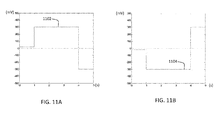
- FIG. 11A illustrates the input signal voltage 1102, i.e., the default analyte measurement input signal, controllably applied by the analyte meter 100 to the exemplary contacts identified above when the test strip 24 is inserted into the test strip port 22 top side up.
- FIG. 11B illustrates the analyte measurement input signal 1104 controllably applied by the analyte meter 100 to the exemplary contacts identified above when the test strip 24 is inserted into the test strip port 22 bottom side up.
- the voltage applied to a top side up oriented test strip 24 includes a voltage of about +20 mV for about one second, followed by a voltage of about +300 mV for about three seconds, followed by a voltage level of about -300 mV for about one second. These applied voltages generate the glucose measurement current in the sample which is used to determine the glucose level of the sample, as described above.
- a test strip 24 determined to be oriented bottom side up in the analyte meter 100 would have the voltage waveform 1104 of FIG. 11B applied thereto, i.e., the inverse analyte measurement input signal, which is the inverse, or reverse polarity, of the default input signal waveform of FIG.
- FIG. 12 illustrates an exemplary flow chart demonstrating a method of operating an analyte meter 100 as described herein.
- the analyte meter 100 receives a test strip 24 inserted into its test strip port 22.
- the analyte meter 100 determines the orientation of the test strip 24 as inserted using any of mechanical, optical, or electrical detection means as described herein, or a combination thereof The determination step 1202 may be performed before or after a sample is applied to the test strip 24 depending upon whether the determination means requires the sample to be present so as to apply test signals thereto, as described above, or whether the test strip 24 includes physical features that are detected by the meter 100 upon insertion.
- the test strip is determined to be in the default orientation at step 1202 then, upon receiving a sample in the sample chamber, the default analyte measurement input signal is applied to the sample at step 1203. If the test strip is determined not to be in the default orientation at step 1202 then, upon receiving a sample in the sample chamber, the inverse analyte measurement input signal (inverse of the default) is applied to the sample at step 1204. At step 1205 the analyte meter 100 receives an output signal from the test strip 24 corresponding to a current level flowing through the sample therein which is used by the analyte meter 100 to determine an analyte level of the sample.
- aspects of the present invention may be embodied as a system, method, or computer program product. Accordingly, aspects of the present invention may take the form of an entirely hardware embodiment, an entirely software embodiment (including firmware, resident software, micro-code, etc.), or an embodiment combining software and hardware aspects that may all generally be referred to herein as a "circuit,” “circuitry,” “module,” 'subsystem” and/or “system.” Furthermore, aspects of the present invention may take the form of a computer program product embodied in one or more computer readable medium(s) having computer readable program code embodied thereon.
- the computer readable medium may be a computer readable signal medium or a computer readable storage medium.
- a computer readable storage medium may be, for example, but not limited to, an electronic, magnetic, optical, electromagnetic, infrared, or semiconductor system, apparatus, or device, or any suitable combination of the foregoing.
- a computer readable storage medium may be any tangible, non-transitory medium that can contain, or store a program for use by or in connection with an instruction execution system, apparatus, or device.
- Program code and/or executable instructions embodied on a computer readable medium may be transmitted using any appropriate medium, including but not limited to wireless, wireline, optical fiber cable, RF, etc., or any suitable combination of the foregoing.
- the computer program instructions may also be loaded onto a computer, other programmable data processing apparatus, or other devices to cause a series of operational steps to be performed on the computer, other programmable apparatus or other devices to produce a computer implemented process such that the instructions which execute on the computer or other programmable apparatus provide processes for implementing the functions/acts specified in the flowchart and/or block diagram block or blocks.
- the various methods described herein can be used to generate software codes using off-the-shelf software development tools.
- the methods may be transformed into other software languages depending on the requirements and the availability of new software languages for coding the methods.
Landscapes
- Life Sciences & Earth Sciences (AREA)
- Health & Medical Sciences (AREA)
- Chemical & Material Sciences (AREA)
- Physics & Mathematics (AREA)
- Biochemistry (AREA)
- Hematology (AREA)
- Chemical Kinetics & Catalysis (AREA)
- Electrochemistry (AREA)
- Biophysics (AREA)
- Analytical Chemistry (AREA)
- Molecular Biology (AREA)
- General Health & Medical Sciences (AREA)
- General Physics & Mathematics (AREA)
- Immunology (AREA)
- Pathology (AREA)
- Investigating Or Analyzing Materials By The Use Of Electric Means (AREA)
- Investigating Or Analysing Biological Materials (AREA)
- Measurement Of The Respiration, Hearing Ability, Form, And Blood Characteristics Of Living Organisms (AREA)
Abstract

Description
- This application generally relates to the field of blood analyte measurement systems and more specifically to portable analyte meters that are configured to detect an orientation of a test strip inserted therein and to correctly adjust a test signal applied thereto in response to the detected orientation.
- Blood glucose measurement systems typically comprise an analyte meter that is configured to receive a biosensor, usually in the form of a test strip. Because many of these systems are portable, and testing can be completed in a short amount of time, patients are able to use such devices in the normal course of their daily lives without significant interruption to their personal routines. A person with diabetes may measure their blood glucose levels several times a day as a part of a self management process to ensure glycemic control of their blood glucose within a target range. A failure to maintain target glycemic control can result in serious diabetes-related complications including cardiovascular disease, kidney disease, nerve damage and blindness.
- There currently exist a number of available portable electronic analyte measurement devices that are designed to automatically activate upon insertion of a test strip. Electrical contacts, or prongs, in the meter establish connections with contact pads on the test strip while a microcontroller in the meter determines, based on electrical signals from the test strip, whether the test strip is properly inserted. Unless the test strip is properly inserted in a proper orientation, however, the device will not activate or, in addition, it may display an error message until the test strip is properly reinserted. This effort may present difficulty for some users who might struggle to correctly orient the test strip prior to insertion, particularly if the test strip is small.
- The accompanying drawings, which are incorporated herein and constitute part of this specification, illustrate presently preferred embodiments of the invention, and, together with the general description given above and the detailed description given below, serve to explain features of the invention (wherein like numerals represent like elements).
-
FIG. 1A illustrates a diagram of an exemplary test strip based analyte measurement system; -
FIG. 1B illustrates a diagram of an exemplary processing system of the test strip based analyte measurement system ofFIG. 1A ; -
FIGs. 2A-C illustrate various views of an exemplary test strip; -
FIGs. 3A-B illustrate various views of another exemplary test strip; -
FIGs. 4A-E illustrate various views of another exemplary test strip; -
FIGs. 5A-B illustrate various views of another exemplary test strip; -
FIGs. 6A-C illustrate various views of another exemplary test strip; -
FIGs. 7A-C illustrate various views of another exemplary test strip; -
FIGs. 8A-C illustrate various views of another exemplary test strip; -
FIGs. 9A-C illustrate various views of another exemplary test strip; -
FIG. 10 illustrates exemplary voltage potential waveforms measured at the electrodes of the test strip depicted inFIGs. 8A-C and 9A-C ; -
FIGs. 11A-B illustrate analyte current measurement voltages applied to the sample in a test strip depending on a determined orientation of the test strip; and -
FIG. 12 illustrates a flow chart of a method of operating the analyte measurement system ofFIGs. 1A-1B . - The following detailed description should be read with reference to the drawings, in which like elements in different drawings are identically numbered. The drawings, which are not necessarily to scale, depict selected embodiments and are not intended to limit the scope of the invention. The detailed description illustrates by way of example, not by way of limitation, the principles of the invention. This description will clearly enable one skilled in the art to make and use the invention, and describes several embodiments, adaptations, variations, alternatives and uses of the invention, including what is presently believed to be the best mode of carrying out the invention.
- As used herein, the terms "patient" or "user" refer to any human or animal subject and are not intended to limit the systems or methods to human use, although use of the subject invention in a human patient represents a preferred embodiment.
- The term "sample" means a volume of a liquid, solution or suspension, intended to be subjected to qualitative or quantitative determination of any of its properties, such as the presence or absence of a component, the concentration of a component, e.g., an analyte, etc. The embodiments of the present invention are applicable to human and animal samples of whole blood. Typical samples in the context of the present invention as described herein include blood, plasma, red blood cells, serum and suspensions thereof.
- The term "about" as used in connection with a numerical value throughout the description and claims denotes an interval of accuracy, familiar and acceptable to a person skilled in the art. The interval governing this term is preferably ± 10 %. Unless specified, the terms described above are not intended to narrow the scope of the invention as described herein and according to the claims.
-
FIG. 1A illustrates ananalyte measurement system 100 that includes ananalyte meter 10. Theanalyte meter 10 is defined by ahousing 11 that retains a data management unit ("DMU") 140 and further includes aport 22 sized for receiving a biosensor. According to one embodiment, theanalyte meter 10 may be a hand held blood glucose meter and the biosensor is provided in the form of atest strip 24 inserted intotest strip port 22 for performing blood glucose measurements. Theanalyte meter 10 further includes a plurality ofuser interface buttons 16, and adisplay 14 as illustrated inFIG. 1A . A predetermined number of glucose test strips may be stored in thehousing 11 and made accessible for use in blood glucose testing. The plurality ofuser interface buttons 16 are associated with theDMU 140 and can be configured to allow the entry of data, to prompt an output of data, to navigate menus presented on thedisplay 14, and to execute commands. Output data can include values representative of analyte concentration presented on thedisplay 14. Input information may include information related to the everyday lifestyle of an individual, such as food intake, medication use, occurrence of health check-ups, and general health condition and exercise levels of an individual. These inputs can be requested via prompts presented on thedisplay 14 and can be stored in a memory module of theanalyte meter 10. Specifically and according to this exemplary embodiment, theuser interface buttons 16 include markings, e.g., up-down arrows, text characters "OK", etc, which allow a user to navigate through the user interface presented on thedisplay 14. Although thebuttons 16 are shown herein as separate switches, a touch screen interface ondisplay 14 with virtual buttons may also be utilized. - The electronic components of the
analyte measurement system 100 can be disposed on, for example, a printed circuit board situated within thehousing 11 and forming theDMU 140 of the herein described system.FIG. 1B illustrates, in simplified schematic form, several of the electronic subsystems disposed within thehousing 11 for purposes of this embodiment. TheDMU 140 includes aprocessing unit 122 in the form of a microprocessor, a microcontroller, an application specific integrated circuit ("ASIC"), a mixed signal processor ("MSP"), a field programmable gate array ("FPGA"), or a combination thereof, and is electrically connected to various electronic modules included on, or connected to, the printed circuit board, as will be described below. Theprocessing unit 122 is electrically connected to, for example, a test strip port connector 104 ("SPC") via an analog front end (AFE)subsystem 125. TheAFE 125 is electrically connected to thestrip port connector 104 during blood glucose testing. To measure a selected analyte concentration, theAFE 125 detects a resistance magnitude change across electrodes ofanalyte test strip 24 which indicates that a blood sample has been applied thereto, using a potentiostat. At a predetermined time after the blood sample has been applied to thetest strip 24, a preset voltage waveform is applied across the sample via the electrodes which generates a an electric current therethrough. TheAFE 125 converts the electric current measurement into digital form for presentation on thedisplay 14. Theprocessing unit 122 can be configured to receive input from thestrip port connector 104, analogfront end subsystem 125, and may also perform a portion of the potentiostat function and the current measurement function. - The
analyte test strip 24 can be in the form of an electrochemical glucose test strip, of which various embodiments are described below. Thetest strip 24 is defined by a nonporous substrate that can include one or more working electrodes.Test strip 24 can also include a plurality of electrical contact pads, where each electrode can be in electrical communication with at least one electrical contact pad, as described below in relation toFIGs. 2A - 9C .Strip port connector 104 can be configured to electrically interface to the electrical contact pads, using electrical contacts in the form of prongs, and form electrical communication with the electrodes.Test strip 24 can include a reagent layer that is disposed over one or more electrodes within thetest strip 24, such as a working electrode. The reagent layer can include an enzyme and a mediator. Exemplary enzymes suitable for use in the reagent layer include glucose oxidase, glucose dehydrogenase (with pyrroloquinoline quinone co-factor, "PQQ"), and glucose dehydrogenase (with flavin adenine dinucleotide co-factor, "FAD"). An exemplary mediator suitable for use in the reagent layer includes ferricyanide, which in this case is in the oxidized form. The reagent layer can be configured to physically transform glucose in the applied sample into an enzymatic by-product and in the process generate an amount of reduced mediator (e.g., ferrocyanide) that is proportional to the glucose concentration of the sample. The working electrode can then be used to apply the preset voltage waveform to the sample and to measure a concentration of the reduced mediator in the form of an electric current. In turn,microcontroller 122 can convert the current magnitude into a glucose concentration for presentation on thedisplay 14. An exemplary analyte meter performing such current measurements is described in U.S. Patent Application Publication No.US 2009/0301899 A1 entitled "System and Method for Measuring an Analyte in a Sample", which is incorporated by reference herein as if fully set forth in this application. - A
display module 119, which may include a display processor and display buffer, is electrically connected to theprocessing unit 122 over theelectrical interface 123 for receiving and displaying output data, and for displaying user interface input options under control ofprocessing unit 122. The structure of the user interface, such as menu options, is stored inuser interface module 103 and is accessible by processingunit 122 for presenting menu options to a user of the bloodglucose measurement system 100. Anaudio module 120 includes aspeaker 121 for outputting audio data received or stored by theDMU 140. Audio outputs can include, for example, notifications, reminders, and alarms, or may include audio data to be replayed in conjunction with display data presented on thedisplay 14. Such stored audio data can be accessed by processingunit 122 and executed as playback data at appropriate times. A volume of the audio output is controlled by theprocessing unit 122, and the volume setting can be stored insettings module 105, as determined by the processor or as adjusted by the user.User input module 102 receives inputs viauser interface buttons 16 which are processed and transmitted to theprocessing unit 122 over theelectrical interface 123. Theprocessing unit 122 may have electrical access to a digital time-of-day clock connected to the printed circuit board for recording dates and times of blood glucose measurements, which may then be accessed, uploaded, or displayed at a later time as necessary. - The
display 14 can alternatively include a backlight whose brightness may be controlled by theprocessing unit 122 via a lightsource control module 115. Similarly, theuser interface buttons 16 may also be illuminated using LED light sources electrically connected toprocessing unit 122 for controlling a light output of the buttons. Thelight source module 115 is electrically connected to the display backlight andprocessing unit 122. Default brightness settings of all light sources, as well as settings adjusted by the user, are stored in asettings module 105, which is accessible and adjustable by theprocessing unit 122. - A
memory module 101, that includes but are not limited to volatile random access memory ("RAM") 112, anon-volatile memory 113, which may comprise read only memory ("ROM") or flash memory, and acircuit 114 for connecting to an external portable memory device, for example, via a USB data port, is electrically connected to theprocessing unit 122 over aelectrical interface 123. External memory devices may include flash memory devices housed in thumb drives, portable hard disk drives, data cards, or any other form of electronic storage devices. The on-board memory can include various embedded applications and stored algorithms in the form of programs executed by theprocessing unit 122 for operation of theanalyte meter 10, as will be explained below. On board memory can also be used to store a history of a user's blood glucose measurements including dates and times associated therewith. Using the wireless transmission capability of theanalyte meter 10 or thedata port 13, as described below, such measurement data can be transferred via wired or wireless transmission to connected computers or other processing devices. - A
wireless module 106 may include transceiver circuits for wireless digital data transmission and reception via one or more internaldigital antennas 107, and is electrically connected to theprocessing unit 122 overelectrical interface 123. The wireless transceiver circuits may be in the form of integrated circuit chips, chipsets, programmable functions operable viaprocessing unit 122, or a combination thereof. Each of the wireless transceiver circuits is compatible with a different wireless transmission standard. For example, awireless transceiver circuit 108 may be compatible with the Wireless Local Area Network IEEE 802.11 standard known as WiFi.Transceiver circuit 108 may be configured to detect a WiFi access point in proximity to theanalyte meter 10 and to transmit and receive data from such a detected WiFi access point. A wireless transceiver circuit 109 may be compatible with the Bluetooth protocol and is configured to detect and process data transmitted from a Bluetooth beacon in proximity to theanalyte meter 10. Awireless transceiver circuit 110 may be compatible with the near field communication ("NFC") standard and is configured to establish radio communication with, for example, another NFC compliant device in proximity to theanalyte meter 10. Awireless transceiver circuit 111 may comprise a circuit for cellular communication with cellular networks and is configured to detect and link to available cellular communication towers. - A
power supply module 116 is electrically connected to all modules in thehousing 11 and to theprocessing unit 122 to supply electric power thereto. Thepower supply module 116 may comprise standard orrechargeable batteries 118 or anAC power supply 117 may be activated when theanalyte meter 10 is connected to a source of AC power. Thepower supply module 116 is also electrically connected toprocessing unit 122 over theelectrical interface 123 for supplying power thereto and so that processingunit 122 can monitor a power level remaining in a battery power mode of thepower supply module 116. -
FIGs. 2A-9C illustrate embodiments of a substantially flat (planar), elongatedtest strip 200 andstrip port connector 104 that may be used for analyte measurement when thetest strip 200 is inserted into atest strip port 22 of theanalyte meter 100 in either of at least two orientations. With reference toFIGs. 2A-B , atest strip 200 is defined by opposing sides herein referred to as atop side 202 and abottom side 204 of thetest strip 200. Referring specifically toFIG. 2C , thetest strip 200 havingconductive contact pads test strip 200, and in whichcontact pad 206 is provided on thetop side 202 andcontact pad 208 is provided on thebottom side 204 of thetest strip 200. Anarrow 210 indicates the direction of insertion of thetest strip 200 into thetest strip port 22, which may be inserted with eitherside test strip 200 facing upwardly. Thetest strip 200 includes asample chamber 212 for receiving a sample therein provided by a user at oneend 213 of thesample chamber 212.Electrodes contact pad sample chamber 212 wherein the sample provided therein makes physical contact with theelectrodes contact pads opposite sides test strip 200. - The
analyte meter 100 that receives thetest strip 200 in itstest strip port 22 usesstrip port connector 104 to make an electrical connection with the pair of thecontact pads contact pads test strip 200. One of theprongs 222 is disposed to contact the bottomside contact pad 208 while anotherprong 220 is configured to electrically connect with the topside contact pad 206 when thetest strip 200 is inserted into thetest strip port 22 in the first orientation. When thetest strip 200 is inserted into thetest strip port 22 in the second orientation, theprong 222 electrically connects with the topside contact pad 206 and theprong 220 electrically connects with the bottomside contact pad 208. - The illustrations of
FIGs. 2A-C depict atest strip 200 whose orientation (i.e., first orientation or second orientation) is detected upon insertion into thetest strip port 22 of theanalyte meter 100. According to this embodiment, a projection, or lug, 214 disposed along a longitudinal edge of thetest strip 200 may be sensed by theanalyte meter 100 to determine the orientation of the test strip, for example, determining whether thetop contact pad 206 faces upward or thebottom contact pad 208 faces upward, indicative of the first orientation and the second orientation, respectively. The first orientation, i.e., thetop contact pad 206 facing upward, may be referred to herein as the default orientation. In one embodiment, theprojection 214 may work in conjunction with a deflectable conductive element in the analyte meter, such as a conductive switch, that transmits a signal upon being deflected by theprojection 214 when thetest strip 200 is inserted in thetest strip port 22 in one orientation, e.g., "top side up", and is not deflected if thetest strip 200 is inserted into thetest strip port 22 in a second orientation, e.g., "bottom side up". Alternatively, a sensing device, such as a mechanical microswitch, photodiode, capacitance sensor, or any other kind of detector may be used to detect the presence or absence of theprojection 214.FIGs. 3A-B illustrate atest strip 300 that is similar in all respects to thetest strip 200 just described with reference toFIGs. 2A-C , except that theprojection 214 of thetest strip 200 is replaced with anindentation 216 in thetest strip 300. Theindentation 216 may be used to detect an orientation of thetest strip 300 at the time of its insertion into theanalyte meter 100, in the direction indicated byarrow 210, such as by using any of the sensing devices identified above that detects the presence or absence of theindentation 216 of thetest strip 300 at the time of insertion of thetest strip 300 or, as described above with respect to theprojection 214, a conductive deflectable element in thetest strip port 22 of theanalyte meter 100, such as a conductive switch, may be used to detect theindentation 216 wherein theindentation 216 positioned over the deflectable element fails to deflect it. -
FIGs. 4A-E illustrate another embodiment of a substantially flat (planar), elongatedtest strip 400 andstrip port connector 104 that may be used for analyte measurement when thetest strip 400 is inserted into atest strip port 22 of theanalyte meter 100 in either of at least two orientations. With reference toFIGs. 4A-B , atest strip 400 is defined by opposing sides herein referred to as atop side 402 and abottom side 404 of thetest strip 400. Referring specifically toFIG. 4C , thetest strip 400 havingconductive contact pads test strip 400, andcontact pads test strip 400, and in whichcontact pads top side 402, andcontact pads bottom side 404 of thetest strip 400. Anarrow 210 indicates the direction of insertion of thetest strip 400 into thetest strip port 22, which may be inserted with eitherside test strip 400 facing upwardly. Thetest strip 400 includes asample chamber 412 for receiving a sample therein provided by a user at oneend 413 of thesample chamber 412.Electrodes contact pad sample chamber 412 wherein the sample provided therein makes physical contact with theelectrodes contact pads opposite sides test strip 400. - In one embodiment, illustrated in
FIGs. 4A-C , theanalyte meter 100 that receives thetest strip 400 in itstest strip port 22 may usestrip port connector 104 to make an electrical connection with a pair of the contact pads, 406 and 426, or 408 and 428, using a strip port connector having at least one pair of electrical contacts, herein referred to as prongs, 420, 424 (FIG. 4C ), that engage the corresponding pair of contact pads 406-426 or 408-428 on thesame side test strip 400, depending on the orientation of thetest strip 400 in thetest strip port 22. Theprongs - In another embodiment, illustrated in
FIGs. 4A-B and 4D-E , theanalyte meter 100 that receives thetest strip 400 in itstest strip port 22 may usestrip port connector 104 to make an electrical connection with the contact pads, 406, 426, 408, and 428, using a strip port connector having at least two sets of electrical contacts, herein referred to as prongs, 420, 424, and 421, 425, (FIG. 4D ), that engage the corresponding pairs of contact pads 406-426 and 408-428 on thesides test strip 400, when thetest strip 400 is inserted in a first (default) orientation in thetest strip port 22. Thetest strip 400 may be inserted in a second orientation, in the manner described herein, wherein prongs, 420, 424, and 421, 425, engage the corresponding pairs of contact pads 408-428 and 426-406 on thesides test strip 400.FIG. 4E illustrates an end view of an embodiment of the two sets of prongs, 420, 424, and 421, 425, whereinupper prong 424 andlower prong 425 are visible in the perspective ofFIG. 4E whileupper prong 420 andlower prong 421 are similarly structured and positioned behindprongs FIG. 4E . The prongs, 420, 424, 421, and 425, comprise flexible spring arms, of which springarms prongs FIG. 4 . Such prongs may be fabricated from a conductive metallic material which flex in a direction away from thetest strip 400 when the test strip is inserted therebetween by a user in the direction indicated byarrow 210. Theprongs electrical connector 423, as well asprongs flexible spring arms contact pads prongs contact pads test strip 400 therebetween when the test strip is inserted and when an analyte measurement process is undertaken by themeter 100, as described herein. - The illustrations of
FIGs. 4A-E depict a system wherein an orientation of test strip 400 (i.e., first orientation or second orientation) is detected upon insertion into thetest strip port 22 of theanalyte meter 100. According to this embodiment, a projection, or lug, 414 disposed along a longitudinal edge of thetest strip 400 may be sensed by theanalyte meter 100 to determine the orientation of the test strip, for example, determining whether thetop contact pads bottom contact pads top contact pads projection 414 may work in conjunction with asensing element 415 in the analyte meter, such as a conductive switch, that transmits a signal upon being deflected by theprojection 414 when thetest strip 400 is inserted in thetest strip port 22 in one orientation, e.g., "top side up" and is not deflected if thetest strip 400 is inserted into thetest strip port 22 in a second orientation, e.g., "bottom side up". Thesensing device 415 may be embodied as a mechanical microswitch, a deflectable conductive element, a photodiode, a capacitance sensor, or any other suitable detector to detect the presence or absence of theprojection 414. -
FIGs. 5A-B illustrate atest strip 500 that is similar in all respects to thetest strip 400 just described with reference toFIGs. 4A-E , except that theprojection 414 of thetest strip 400 is replaced with anindentation 416 in thetest strip 500. Theindentation 416 may be used to detect an orientation of thetest strip 500 at the time of its insertion into theanalyte meter 100, in the direction indicated byarrow 210, for example, using asensing device 415, such as a mechanical microswitch, photodiode, capacitance sensor, or any other kind of detector that senses the presence or absence of theindentation 416 of thetest strip 500 or, as described above with respect to theprojection 414, a deflectable element in thetest strip port 22 of theanalyte meter 100 may be used to detect theindentation 416 wherein theindentation 416 positioned over the deflectable element fails to deflect it. Although aprojection 414 and anindentation 416 have been described as exemplary physical features that may be used to detect an orientation of atest strip 24, such examples should not be interpreted as limiting the embodiments described herein. Other detectable physical features may be formed or fabricated in thetest strip 24 without departing from the spirit of the embodiments described herein. For example, a magnetic strip or indicator in thetest strip 24 may be detected by a magnetic relay in thetest strip port 22. Likewise, rotationally variant or invariant optical features may be printed or embedded in thetest strip 24 which may be detected by optical readers, such as 1D or 2D barcode scanners, or an optical pattern matching system in theanalyte meter 100, as a further example. In addition, the various mechanisms and methods described herein to determinetest strip 24 orientation may be used in combination, which may serve as a verification of adetermined test strip 24 orientation. -
FIGs. 6A-C illustrate another embodiment of a substantially flat (planar), elongatedtest strip 600 andstrip port connector 104 that may be used for analyte measurement when thetest strip 600 is inserted into atest strip port 22 of theanalyte meter 100 in either of at least two orientations. With reference toFIGs. 6A-B , thetest strip 600 is defined by opposing sides herein referred to as atop side 602 and abottom side 604 of thetest strip 600. Referring specifically toFIG. 6C , thetest strip 600 havingconductive contact pads test strip 600, and in whichcontact pad 606 is provided on thetop side 602 andcontact pad 208 is provided on thebottom side 604 of thetest strip 600. Anarrow 210 indicates the direction of insertion of thetest strip 600 into thetest strip port 22, which may be inserted with eitherside test strip 600 facing upwardly. Thetest strip 600 includes asample chamber 612 for receiving a sample therein provided by a user at oneend 613 of thesample chamber 612.Electrodes contact pad sample chamber 612 wherein the sample provided therein makes physical contact with theelectrodes contact pads opposite sides test strip 600. - One of the
contact pads 606 comprises aborder 605 that is non-conductive. Thisborder 605 may be formed by ablation of the conductive material of thecontact pad 606, such as using laser ablation, or, in another embodiment, the region surrounded by thenon-conducive border 605 could be entirely formed as a non-conductive patch. Theanalyte meter 100 into which the test strip is inserted comprises twoprongs test strip 600, wherein oneprong 620 is used for electrically contacting the region of thecontact pad 606 within theborder 605 and theother prong 621 for contacting the region of thecontact pad 606 outside theborder 605, when thetop side 602 of the test strip is facing upward, as indicated by the contact points 614. A resistance between these twoprongs analyte meter 100 can be measured while theprongs border 605 and the region outside theborder 605 ofcontact pad 606, respectively. A high resistance will be measured because there is no conductive path between theprongs contact points 614, thereby indicating the orientation of thetest strip 600 as being "top side up". Thus, a first orientation of thetest strip 600 may be determined based on the high resistance, and may be referred to herein as the default orientation. - The two
prongs test strip 600 may electrically connect to thecontact pad 608 when thetest strip 600 is inserted into the test strip port with thebottom side 604 facing upward (FIG. 6B ) as indicated by the contact points 615. A resistance between theprongs analyte meter 100 can be measured while theprongs contact pad 608. A low resistance will be measured becausecontact pad 608 is entirely conductive, thereby indicating the orientation of thetest strip 600 as being "bottom side up". Thus, a second orientation of thetest strip 600 may be determined based on the low measured resistance. Based on these measured resistances using twoprongs test strip 600,analyte meter 100 may determine in which orientation thetest strip 600 has been inserted. - The
analyte meter 100 that receives thetest strip 600 in itstest strip port 22 usesstrip port connector 104 to make an electrical connection with thecontact pads contact pads test strip 600. One of theprongs 622 is disposed to contact the bottomside contact pad 608 while anotherprong 621 is configured to electrically connect with the topside contact pad 606 when the test strip is inserted into thetest strip port 22 in the first orientation. When thetest strip 600 is inserted into thetest strip port 22 in the second orientation, theprong 622 electrically connects with the topside contact pad 606 and theprong 621 electrically connects with the bottomside contact pad 608. -
FIGs. 7A-C illustrate another embodiment of a substantially flat (planar), elongatedtest strip 700 andstrip port connector 104 that may be used for analyte measurement when thetest strip 700 is inserted into atest strip port 22 of theanalyte meter 100 in either of at least two orientations. With reference toFIGs. 7A-B , atest strip 700 is defined by opposing sides herein referred to as atop side 702 and abottom side 704 of thetest strip 700. Referring specifically toFIG. 7C , thetest strip 700 havingconductive contact pads test strip 700, andcontact pads test strip 700, and in whichcontact pads top side 702, andcontact pads bottom side 704 of thetest strip 700. Thearrow 210 indicates the direction of insertion of thetest strip 700 into thetest strip port 22, which may be inserted with eitherside test strip 700 facing upwardly. Thetest strip 700 includes asample chamber 712 for receiving a sample therein provided by a user at oneend 713 of thesample chamber 712.Electrodes contact pad sample chamber 712 wherein the sample provided therein makes physical contact with theelectrodes contact pads opposite sides test strip 700. - Two of the
contact pads border borders contact pads non-conducive borders analyte meter 100 into which thetest strip 700 is inserted comprises twoprongs test strip 700. One of theprongs 720 is used for electrically contacting the region of thecontact pad 706 within theborder 705 and theother prong 721 for contacting the region of thecontact pad 706 outside theborder 705, when thetop side 702 of the test strip is facing upward, as indicated by the contact points 714. A resistance between these twoprongs analyte meter 100 can be measured while theprongs border 705 and the region outside theborder 705 ofcontact pad 706, respectively. A high resistance will be measured because there is no conductive path between theprongs contact points 714, thereby indicating the orientation of thetest strip 700 as being "top side up". Thus, a first orientation of thetest strip 700 may be determined based on the high resistance, and may be referred to herein as the default orientation. - The two
prongs test strip 700 may electrically connect to thecontact pad 708 when thetest strip 700 is inserted into the test strip port with thebottom side 704 facing upward (FIG. 7B ) as indicated by the contact points 715. A resistance between theprongs analyte meter 100 can be measured while theprongs contact pad 708. A low resistance will be measured becausecontact pad 708 is entirely conductive, thereby indicating the orientation of thetest strip 700 as being "bottom side up". Thus, a second orientation of thetest strip 700 may be determined based on the low measured resistance. Based on these measured resistances using twoprongs test strip 700,analyte meter 100 may determine in which orientation thetest strip 700 has been inserted. - The
analyte meter 100 that receives thetest strip 700 in itstest strip port 22 usesstrip port connector 104 to make an electrical connection with a pair of the contact pads, 706 and 726, or 708 and 728, using a strip port connector having at least one pair of electrical contacts, herein referred to as prongs, 721, 724, that engage the corresponding pair of the contact pads 706-726, or 708-728, on thesame side test strip 700 depending on the orientation of thetest strip 700 in thetest strip port 22. Theprongs -
FIGs. 8A-C illustrate embodiments of a substantially flat (planar), elongatedtest strip 800 andstrip port connector 104 that may be used for analyte measurement when thetest strip 800 is inserted into atest strip port 22 of theanalyte meter 100 in either of at least two orientations. With reference toFIGs. 8A-B , atest strip 800 is defined by opposing sides herein referred to as atop side 802 and abottom side 804 of thetest strip 800. Referring specifically toFIG. 8C , thetest strip 800 havingconductive contact pads test strip 800, and in whichcontact pad 806 is provided on thetop side 802 andcontact pad 808 is provided on thebottom side 804 of thetest strip 800. Anarrow 210 indicates the direction of insertion of thetest strip 800 into thetest strip port 22, which may be inserted with eitherside test strip 800 facing upwardly. Thetest strip 800 includes asample chamber 812 for receiving a sample therein provided by a user at oneend 813 of thesample chamber 812.Electrodes contact pad sample chamber 812 wherein the sample provided therein makes physical contact with theelectrodes contact pads opposite sides test strip 800. - The
analyte meter 100 that receives thetest strip 800 in itstest strip port 22 usesstrip port connector 104 to make an electrical connection with the pair of thecontact pads contact pads test strip 800. One of theprongs 822 is disposed to contact the bottomside contact pad 808 while anotherprong 820 is configured to connect with the topside contact pad 806 when thetest strip 800 is inserted into thetest strip port 22 in the first orientation, i.e., the "default" orientation. When thetest strip 800 is inserted into thetest strip port 22 in the second orientation, theprong 822 electrically connects with the topside contact pad 806 and theprong 820 electrically connects with the bottomside contact pad 808. -
FIGs. 9A-C illustrate another embodiment of a substantially flat (planar), elongatedtest strip 900 andstrip port connector 104 that may be used for analyte measurement when thetest strip 900 is inserted into atest strip port 22 of theanalyte meter 100 in either of at least two orientations. With reference toFIGs. 9A-B , atest strip 900 is defined by opposing sides herein referred to as atop side 902 and abottom side 904 of thetest strip 900. Referring specifically toFIG. 9C , thetest strip 900 havingconductive contact pads test strip 900, andcontact pads test strip 900, and in whichcontact pads top side 902, andcontact pads bottom side 904 of thetest strip 900. Anarrow 210 indicates the direction of insertion of thetest strip 900 into thetest strip port 22, which may be inserted with eitherside test strip 900 facing upwardly. A default orientation of thetest strip 900 may be referenced herein as theside 902 facing upwardly. Thetest strip 900 includes asample chamber 912 for receiving a sample therein provided by a user at oneend 913 of thesample chamber 912.Electrodes contact pad sample chamber 912 wherein the sample provided therein makes physical contact with theelectrodes contact pads opposite sides test strip 900. - The
analyte meter 100 that receives thetest strip 900 in itstest strip port 22 usesstrip port connector 104 to make an electrical connection with a pair of thecontact pads same side test strip 900 depending on the orientation of thetest strip 900 in thetest strip port 22. Theprongs - The illustrations in
FIGs. 8A-C and 9A-C depicttest strips test strip port 22 of theanalyte meter 100 and upon providing a sample in thesample chamber electrodes FIGs. 8A ,9A, and 9B , respectively, although opposing electrodes corresponding to these may, instead, be designated as working electrodes. The mediator may comprise one or more components that mix with the sample upon application in thesample chamber electrodes analyte meter contacts sample chamber sample chamber electrodes electrode 807 oftest strip 800 and onelectrodes test strip 900, for example. This results in a time duration during which the orientation of the test strip may be ascertained by detecting the asymmetric electrical or electrochemical property of these electrodes. - An example of the asymmetric electrical/electrochemical properties just described are illustrated in
FIG. 10 . In this example,time 0 on the horizontal axis, measured in milliseconds, indicates the time at which the sample is applied to thetest strip electrodes test strip 800 orelectrodes test strip 900, for example, the voltage potential as measured between these electrodes is indicated by the voltage swings 1002, 1004 which occurs prior to the mediator mixing thoroughly with the provided sample. In this example embodiment, open circuit galvanostatic potentiometry is used to measure the voltage potential. The voltage swings 1002 and 1004 depicted inFIG. 10 illustrate six test cases, three in each of a positive and a negative going direction, that clearly demonstrate a detectable voltage potential generated by application of a sample in thetest strip electrode milliseconds 1006 after application of the sample to the test strip wherein the positive-or negative going voltage potential waveform reaches a positive or negative peak and may be easily and clearly detected by programmed operation of themicrocontroller 122 to determine an orientation of thetest strip test strip port 22 of theanalyte meter 100. The positive or negative going voltage potential waveform may even be detected up to about 1000 milliseconds after application of the sample to the test strip. In the example graph illustrated inFIG. 10 , the positive goingvoltage swings 1002 indicate atopside test strip voltage swings 1004 indicate atopside test strip - One advantage of using a short duration, e.g. less than 1 s duration or less than 300 ms, open circuit (0 amps) galvanostatic potentiometry is that it enables the potentiometric insertion orientation signal to be detected with minimal interference or impact upon the subsequent amperometric glucose measurement current because neither an external potential is applied nor current drawn from within the electrochemical cell over the duration of this orientation detection measurement phase.
- In all of the above examples illustrated in
FIGs. 2A - 9C describing a determination oftest strip 24 insertion orientation in thetest strip port 22 of theanalyte meter 100, after the orientation of the test strip is determined the glucose measurement current may be applied to the sample through theanalyte meter 100contact 220 in the example ofFIG. 2C , thecontact 420 in the example ofFIG. 4C , thecontact 621 in the example ofFIG. 6C , thecontact 721 in the example ofFIG. 7C , the contact 820 n the example ofFIG. 8C , and thecontact 920 in the example ofFIG. 9C . The glucose measurement current is applied in an appropriate polarity so that the blood glucose level may be measured correctly. The application of the correct polarity of a glucose measurement input signal includes themicrocontroller 122 programmably controlling a circuit capable of inverting or not inverting the polarity the signal applied to theanalyte meter 100 contact and thereby to a contact pad of thetest strip 24 depending on the aforementioned determination of the orientation of thetest strip 24. -
FIG. 11A illustrates theinput signal voltage 1102, i.e., the default analyte measurement input signal, controllably applied by theanalyte meter 100 to the exemplary contacts identified above when thetest strip 24 is inserted into thetest strip port 22 top side up.FIG. 11B illustrates the analytemeasurement input signal 1104 controllably applied by theanalyte meter 100 to the exemplary contacts identified above when thetest strip 24 is inserted into thetest strip port 22 bottom side up. In one embodiment, the voltage applied to a top side up orientedtest strip 24 includes a voltage of about +20 mV for about one second, followed by a voltage of about +300 mV for about three seconds, followed by a voltage level of about -300 mV for about one second. These applied voltages generate the glucose measurement current in the sample which is used to determine the glucose level of the sample, as described above. Atest strip 24 determined to be oriented bottom side up in theanalyte meter 100 would have thevoltage waveform 1104 ofFIG. 11B applied thereto, i.e., the inverse analyte measurement input signal, which is the inverse, or reverse polarity, of the default input signal waveform ofFIG. 11A , through theanalyte meter 100 contacts as identified above. An exemplary analyte meter applying such analyte measurement input signals for measuring glucose current is described in U.S. Patent Application Publication No.US 2009/0084687 A1 entitled "Systems and Methods of Discriminating Control Solution from a Physiological Sample", which is incorporated by reference herein as if fully set forth in this application. -
FIG. 12 illustrates an exemplary flow chart demonstrating a method of operating ananalyte meter 100 as described herein. Atstep 1201 theanalyte meter 100 receives atest strip 24 inserted into itstest strip port 22. Atstep 1202 theanalyte meter 100 determines the orientation of thetest strip 24 as inserted using any of mechanical, optical, or electrical detection means as described herein, or a combination thereof Thedetermination step 1202 may be performed before or after a sample is applied to thetest strip 24 depending upon whether the determination means requires the sample to be present so as to apply test signals thereto, as described above, or whether thetest strip 24 includes physical features that are detected by themeter 100 upon insertion. If the test strip is determined to be in the default orientation atstep 1202 then, upon receiving a sample in the sample chamber, the default analyte measurement input signal is applied to the sample atstep 1203. If the test strip is determined not to be in the default orientation atstep 1202 then, upon receiving a sample in the sample chamber, the inverse analyte measurement input signal (inverse of the default) is applied to the sample atstep 1204. Atstep 1205 theanalyte meter 100 receives an output signal from thetest strip 24 corresponding to a current level flowing through the sample therein which is used by theanalyte meter 100 to determine an analyte level of the sample. - As will be appreciated by one skilled in the art, aspects of the present invention may be embodied as a system, method, or computer program product. Accordingly, aspects of the present invention may take the form of an entirely hardware embodiment, an entirely software embodiment (including firmware, resident software, micro-code, etc.), or an embodiment combining software and hardware aspects that may all generally be referred to herein as a "circuit," "circuitry," "module," 'subsystem" and/or "system." Furthermore, aspects of the present invention may take the form of a computer program product embodied in one or more computer readable medium(s) having computer readable program code embodied thereon.
- Any combination of one or more computer readable medium(s) may be utilized. The computer readable medium may be a computer readable signal medium or a computer readable storage medium. A computer readable storage medium may be, for example, but not limited to, an electronic, magnetic, optical, electromagnetic, infrared, or semiconductor system, apparatus, or device, or any suitable combination of the foregoing. More specific examples of the computer readable storage medium would include the following: an electrical connection having one or more wires, a portable computer diskette, a hard disk, a random access memory (RAM), a read-only memory (ROM), an erasable programmable read-only memory (EPROM or Flash memory), an optical fiber, a portable compact disc read-only memory (CD-ROM), an optical storage device, a magnetic storage device, or any suitable combination of the foregoing. In the context of this document, a computer readable storage medium may be any tangible, non-transitory medium that can contain, or store a program for use by or in connection with an instruction execution system, apparatus, or device.
- Program code and/or executable instructions embodied on a computer readable medium may be transmitted using any appropriate medium, including but not limited to wireless, wireline, optical fiber cable, RF, etc., or any suitable combination of the foregoing.
- The computer program instructions may also be loaded onto a computer, other programmable data processing apparatus, or other devices to cause a series of operational steps to be performed on the computer, other programmable apparatus or other devices to produce a computer implemented process such that the instructions which execute on the computer or other programmable apparatus provide processes for implementing the functions/acts specified in the flowchart and/or block diagram block or blocks.
- Furthermore, the various methods described herein can be used to generate software codes using off-the-shelf software development tools. The methods, however, may be transformed into other software languages depending on the requirements and the availability of new software languages for coding the methods.
-
- 10
- analyte meter
- 11
- housing, meter
- 13
- data port
- 14
- display
- 16
- user interface buttons
- 22
- strip port connector
- 24
- test strip
- 100
- analyte measurement system
- 101
- memory module
- 102
- buttons module
- 103
- user interface module
- 104
- strip port connector
- 105
- microcontroller settings module
- 106
- transceiver module
- 107
- antenna
- 108
- WiFi module
- 109
- Bluetooth module
- 110
- NFC module
- 111
- GSM module
- 112
- RAM module
- 113
- ROM module
- 114
- external storage
- 115
- light source module
- 116
- power supply module
- 117
- AC power supply
- 118
- battery power supply
- 119
- display module
- 120
- audio module
- 121
- speaker
- 122
- microcontroller (processing unit)
- 123
- communication interface
- 125
- analog front end subsystem
- 140
- data management unit
- 200
- test strip
- 202
- test strip top side
- 204
- test strip bottom side
- 206
- contact pad
- 207
- electrode
- 208
- contact pad
- 209
- electrode
- 210
- direction (arrow)
- 212
- sample chamber
- 213
- one end of sample chamber
- 214
- projection (lug)
- 216
- indentation
- 220
- contact (prong)
- 222
- contact (prong)
- 300
- test strip
- 400
- test strip
- 402
- test strip top side
- 404
- test strip bottom side
- 406
- contact pad
- 407
- electrode
- 408
- contact pad
- 409
- electrode
- 410
- spring arm
- 411
- spring arm
- 412
- sample chamber
- 413
- one end of sample chamber
- 414
- projection (lug)
- 415
- sensor for projection (lug) or indentation
- 416
- indentation
- 420
- contact (prong)
- 421
- contact (prong)
- 423
- electrical connector
- 424
- contact (prong)
- 425
- contact (prong)
- 426
- contact pad
- 427
- electrode
- 428
- contact pad
- 429
- electrode
- 500
- test strip
- 600
- test strip
- 602
- test strip top side
- 604
- test strip bottom side
- 605
- non-conductive border
- 606
- contact pad
- 607
- electrode
- 608
- contact pad
- 609
- electrode
- 612
- sample chamber
- 613
- one end of sample chamber
- 614
- contact points
- 615
- contact points
- 620
- contact (prong)
- 621
- contact (prong)
- 622
- contact (prong)
- 700
- test strip
- 702
- test strip top side
- 704
- test strip bottom side
- 706
- contact pad
- 707
- electrode
- 708
- contact pad
- 709
- electrode
- 712
- sample chamber
- 713
- one end of sample chamber
- 714
- contact points
- 715
- contact points
- 720
- contact (prong)
- 721
- contact (prong)
- 724
- contact (prong)
- 725
- non-conductive border
- 726
- contact pad
- 727
- electrode
- 728
- contact pad
- 729
- electrode
- 800
- test strip
- 802
- test strip top side
- 804
- test strip bottom side
- 806
- contact pad
- 807
- electrode
- 808
- contact pad
- 809
- electrode
- 812
- sample chamber
- 813
- one end of sample chamber
- 820
- contact (prong)
- 822
- contact (prong)
- 900
- test strip
- 902
- test strip top side
- 904
- test strip bottom side
- 906
- contact pad
- 907
- electrode
- 908
- contact pad
- 909
- electrode
- 912
- sample chamber
- 913
- one end of sample chamber
- 920
- contact (prong)
- 924
- contact (prong)
- 926
- contact pad
- 927
- electrode
- 928
- contact pad
- 929
- electrode
- 1002
- voltage swing (positive)
- 1004
- voltage swing (negative)
- 1006
- time point
- 1102
- applied voltage waveform
- 1104
- applied voltage waveform
- 1201
- step - receive test strip in test strip port
- 1202
- step - is test strip in default orientation
- 1203
- step - apply default analyte measurement input signal
- 1204
- step - apply inverse analyte measurement input signal
- 1205
- step - determine analyte level based on signal received from test strip
- While the invention has been described in terms of particular variations and illustrative figures, those of ordinary skill in the art will recognize that the invention is not limited to the variations or figures described. In addition, where methods and steps described above indicate certain events occurring in certain order, those of ordinary skill in the art will recognize that the ordering of certain steps may be modified and that such modifications are in accordance with the variations of the invention. Additionally, certain of the steps may be performed concurrently in a parallel process when possible, as well as performed sequentially as described above. Therefore, to the extent there are variations of the invention, which are within the spirit of the disclosure or equivalent to the inventions found in the claims, it is the intent that this patent will cover those variations as well.
- The following are embodiments which may or may not be claimed:
- Embodiment 1. An analyte meter comprising:
- a test strip port configured for receiving a test strip, the test strip port comprising:
- a strip port connector comprising a plurality of contacts each configured to electrically connect to a corresponding contact pad disposed on the test strip when the test strip is inserted into the test strip port; and
- a test strip orientation detector for detecting an orientation of the test strip; and
- a control circuit electrically connected to the strip port connector and configured to apply a predetermined signal to a first contact of said connector in response to a first signal from the test strip orientation detector and to apply a second predetermined signal to the first contact in response to a second signal from the test strip orientation detector.
- a test strip port configured for receiving a test strip, the test strip port comprising:
-
Embodiment 2. The analyte meter of embodiment 1, wherein said test strip orientation detector comprises a sensor configured for sensing a feature of the test strip, said feature being indicative of the orientation of said test strip. -
Embodiment 3. The analyte meter ofembodiment 2, wherein said sensor is configured for contacting a projection on the test strip indicative of the orientation of said test strip and transmitting an electrical signal based on contact with said projection. - Embodiment 4. The analyte meter of
embodiment 2, wherein said sensor is configured for optically detecting a portion of the test strip indicative of the orientation of the test strip and transmitting an electrical signal to the control circuit upon optically detecting the portion of the test strip. -
Embodiment 5. The analyte meter of embodiment 1, wherein the test strip comprises a first side and a second side, the second side opposite the first side, and wherein a first one of the contacts electrically connects to a first contact pad on the first side of the test strip simultaneously with a second one of the contacts electrically connecting to a second contact pad on a second side of the test strip. - Embodiment 6. The analyte meter of embodiment 1, wherein the test strip comprises a first side and a second side, the second side opposite the first side, and wherein a first one of the contacts electrically connects to a first contact pad on the first side of the test strip simultaneously with a second one of the contacts electrically connecting to a second contact pad on the first side of the test strip.
- Embodiment 7. The analyte meter of embodiment 1, wherein said test strip orientation detector comprises a voltage measurement circuit.
- Embodiment 8. The analyte meter of embodiment 1, wherein the control circuit is configured to electrically detect the orientation of the test strip after a sample is applied thereto.
- Embodiment 9. The analyte meter of embodiment 1, wherein the test strip orientation detector comprises a circuit for measuring a magnitude of a resistance between two of the contacts.
-
Embodiment 10. The analyte meter of embodiment 1, wherein the orientation detector is configured to electrically detect the orientation of the test strip when the test strip is inserted into the test strip port and before a sample is applied thereto. -
Embodiment 11. An analyte meter comprising:- a meter housing;
- a test strip port disposed in said housing and configured for receiving a test strip, the test strip port having a strip port connector comprising a plurality of contacts configured to electrically connect to corresponding electrodes disposed on the test strip when the test strip is inserted into the test strip port; and
- a control circuit electrically connected to the strip port connector for applying an electrical signal to the test strip and for detecting an electrical response to the electrical signal from the test strip, the electrical response from the test strip indicative of an orientation of the test strip, wherein the control circuit is configured to apply a first analyte measurement signal to a first contact in the strip port connector in response to detecting a first orientation of the test strip, the first analyte measurement signal for generating a measurable current in a sample applied to the test strip, and wherein the control circuit is configured to apply a second analyte measurement signal to the first contact in the strip port connector in response to detecting a second orientation of the test strip, the second analyte measurement signal different from the first analyte measurement signal for generating the measurable current in the sample applied to the test strip.
- Embodiment 12. The analyte meter of
embodiment 11, wherein the test strip comprises a first side and an opposing second side, wherein the first contact of said strip port connector electrically connects to a contact pad on the first side of the test strip simultaneously with a second contact of said strip port connector electrically connecting to a second contact pad on the second side of the test strip. -
Embodiment 13. The analyte meter ofembodiment 11, wherein the test strip comprises a first side and an opposing second side, wherein the first contact of said strip port connector electrically connects to a first contact pad on the first side of the test strip simultaneously with a second contact of said strip port connector electrically connecting to a second contact pad on the first side of the test strip. -
Embodiment 14. The analyte meter ofembodiment 11, wherein a measured level of the measurable current in the sample corresponds to an analyte level of the sample. - Embodiment 15. The analyte meter of
embodiment 14, wherein the analyte level of the sample comprises a glucose level of the sample. -
Embodiment 16. The analyte meter ofembodiment 11, wherein the control circuit is configured to electrically detect the electrical response to the electrical signal from the test strip within about 300 ms after the sample is applied thereto. - Embodiment 17. The analyte meter of
embodiment 11, wherein the electrical response of the test strip is a magnitude of a resistance measured between two of the contacts. - Embodiment 18. The analyte meter of embodiment 17, wherein the control circuit is configured to measure the magnitude of the resistance between said two of the contacts when the test strip is inserted into the test strip port and before the sample is applied thereto.
- Embodiment 19. The analyte meter of
embodiment 11, wherein the first analyte measurement signal and the second analyte measurement signal are inversely related. - Embodiment 20. A test strip comprising:
- a planar, elongated substrate, said test strip having a first side and an opposing second side, said substrate further including a first end and an opposite second end;
- a sample chamber disposed between the first end and the second end, the sample chamber for receiving a sample applied thereto; and
- a plurality of electrodes configured to drive an analyte measurement current through the sample applied to the test strip, at least one electrode on the first side of the test strip being proximate the first end of the test strip, and at least one electrode on the second side of the test strip being proximate the second end of the test strip, said test strip being configured to be inserted in at least two orientations in an analyte test meter for testing for an analyte of interest in the sample.
- Embodiment 21. A test strip comprising:
- a planar, elongated substrate, said test strip having a first side and an opposing second side, said substrate further including a first end and an opposite second end;
- a sample chamber disposed between the first end and the second end, the sample chamber for receiving a sample applied thereto; and
- a plurality of electrodes configured to drive an analyte measurement current through the sample applied to the test strip, a first electrode disposed on the first side proximate the first end of the test strip, a second electrode disposed on the first side proximate the second end of the test strip, a third electrode disposed on the second side proximate the first end of the test strip, and a fourth electrode disposed on the second side proximate the second end of the test strip.
-
Embodiment 22. The test strip of embodiment 19, wherein the first electrode comprises a high resistance portion configured to abut at least one electrical contact of an analyte meter when the test strip is inserted therein in a first orientation, and wherein the fourth electrode comprises a low resistance portion configured to abut said at least one electrical contact of an analyte meter when the test strip is inserted therein in a second orientation different from the first orientation. - Embodiment 23. A method of operating an analyte meter, the method comprising:
- receiving a test strip in a test strip port of the analyte meter using a test strip configured to be inserted into the test strip port in at least two orientations;
- determining an orientation of the received test strip; and
- applying an electrical measurement signal to a sample in the test strip, the electrical measurement signal automatically selected from a plurality of electrical measurement signals based on the determined orientation of the received test strip, to determine an analyte level in the sample.
-
Embodiment 24. The method of embodiment 23, wherein the step of determining the orientation of the test strip comprises electrically connecting contacts in the test strip port to a contact pad disposed on the received test strip and detecting a resistance thereof, wherein a magnitude of the resistance is indicative of the orientation of the received test strip. - Embodiment 25. The method of embodiment 23, wherein the step of determining comprises detecting a physical feature of the test strip employing a sensor in the test strip port, the detected physical feature indicative of the orientation of the received test strip when the test strip is inserted into the test strip port.
- Embodiment 26. The method of embodiment 25, wherein the step of detecting a physical feature of the test strip employing a sensor comprises employing one of a deflectable switch, a magnetic relay, a photodetector, an optical sensor, or a combination thereof.
- Embodiment 27. The method of embodiment 23, wherein the step of determining the orientation of the test strip comprises receiving the sample in the test strip and measuring a voltage across the received sample prior to applying the electrical measurement signal to the sample.
- Embodiment 28. The method of embodiment 27, wherein the step of measuring the voltage across the received sample comprises measuring a polarity of the voltage across the received sample within about 300 ms after receiving the sample in the test strip.
- Embodiment 29. A test strip and strip port connector (SPC) system comprising:
- a test strip with a lug disposed on a longitudinal edge thereof; and
- a strip port connector (SPC) including:
- a first set of electrical contacts configured to make operable contact with electrical contact pads of the test strip inserted into the SPC in a first orientation;
- a second set of electrical contacts configured to make operable contact with the electrical contact pads of the test strip inserted into the SPC in a second orientation; and
- a test strip orientation detection mechanism configured to distinguish the first and second orientations based on positioning of the lug in the SPC.
- Embodiment 30. A method for employing a hand-held test meter with a test strip comprising:
- inserting the test strip into an strip port connector (SPC) of a hand-held meter, the test strip having a lug disposed on a longitudinal edge thereof;
- making electrical contact to contact pads of the test strip using one of:
- a first set of electrical contacts configured to make operable contact with electrical contact pads of the test strip inserted into the SPC in a first orientation; and
- a second set of electrical contacts configured to make operable contact with the electrical contact pads of the test strip inserted into the SPC in a second orientation; and
- distinguishing the first and second orientations based on positioning of the lug in the SPC using a test strip orientation mechanism of the SPC.
Claims (18)
- An analyte meter comprising:a test strip port configured for receiving a test strip, the test strip port comprising:a strip port connector comprising a plurality of contacts each configured to electrically connect to a corresponding contact pad disposed on the test strip when the test strip is inserted into the test strip port; anda test strip orientation detector for detecting an orientation of the test strip; anda control circuit electrically connected to the strip port connector and configured to apply a predetermined signal to a first contact of said connector in response to a first signal from the test strip orientation detector and to apply a second predetermined signal to the first contact in response to a second signal from the test strip orientation detector.
- The analyte meter of claim 1, wherein said test strip orientation detector comprises a sensor configured for sensing a feature of the test strip, said feature being indicative of the orientation of said test strip.
- The analyte meter of claim 2, wherein said sensor is configured for contacting a projection on the test strip indicative of the orientation of said test strip and transmitting an electrical signal based on contact with said projection.
- The analyte meter of claim 2, wherein said sensor is configured for optically detecting a portion of the test strip indicative of the orientation of the test strip and transmitting an electrical signal to the control circuit upon optically detecting the portion of the test strip.
- The analyte meter of claim 1, wherein the test strip comprises a first side and a second side, the second side opposite the first side, and wherein a first one of the contacts electrically connects to a first contact pad on the first side of the test strip simultaneously with a second one of the contacts electrically connecting to a second contact pad on a second side of the test strip.
- The analyte meter of claim 1, wherein the test strip comprises a first side and a second side, the second side opposite the first side, and wherein a first one of the contacts electrically connects to a first contact pad on the first side of the test strip simultaneously with a second one of the contacts electrically connecting to a second contact pad on the first side of the test strip.
- The analyte meter of claim 1, wherein said test strip orientation detector comprises a voltage measurement circuit.
- The analyte meter of claim 1, wherein the control circuit is configured to electrically detect the orientation of the test strip after a sample is applied thereto.
- The analyte meter of claim 1, wherein the test strip orientation detector comprises a circuit for measuring a magnitude of a resistance between two of the contacts.
- The analyte meter of claim 1, wherein the orientation detector is configured to electrically detect the orientation of the test strip when the test strip is inserted into the test strip port and before a sample is applied thereto.
- A test strip comprising:a planar, elongated substrate, said test strip having a first side and an opposing second side, said substrate further including a first end and an opposite second end;a sample chamber disposed between the first end and the second end, the sample chamber for receiving a sample applied thereto; anda plurality of electrodes configured to drive an analyte measurement current through the sample applied to the test strip, at least one electrode on the first side of the test strip being proximate the first end of the test strip, and at least one electrode on the second side of the test strip being proximate the second end of the test strip, said test strip being configured to be inserted in at least two orientations in an analyte test meter for testing for an analyte of interest in the sample.
- A method of operating an analyte meter, the method comprising:receiving a test strip in a test strip port of the analyte meter using a test strip configured to be inserted into the test strip port in at least two orientations;determining an orientation of the received test strip; andapplying an electrical measurement signal to a sample in the test strip, the electrical measurement signal automatically selected from a plurality of electrical measurement signals based on the determined orientation of the received test strip, to determine an analyte level in the sample.
- The method of claim 12, wherein the step of determining the orientation of the test strip comprises electrically connecting contacts in the test strip port to a contact pad disposed on the received test strip and detecting a resistance thereof, wherein a magnitude of the resistance is indicative of the orientation of the received test strip.
- The method of claim 12, wherein the step of determining comprises detecting a physical feature of the test strip employing a sensor in the test strip port, the detected physical feature indicative of the orientation of the received test strip when the test strip is inserted into the test strip port.
- The method of claim 14, wherein the step of detecting a physical feature of the test strip employing a sensor comprises employing one of a deflectable switch, a magnetic relay, a photodetector, an optical sensor, or a combination thereof.
- The method of claim 12, wherein the step of determining the orientation of the test strip comprises receiving the sample in the test strip and measuring a voltage across the received sample prior to applying the electrical measurement signal to the sample.
- The method of claim 16, wherein the step of measuring the voltage across the received sample comprises measuring a polarity of the voltage across the received sample within about 300 ms after receiving the sample in the test strip.
- A test strip and strip port connector (SPC) system comprising:a test strip with a lug disposed on a longitudinal edge thereof; anda strip port connector (SPC) including:a first set of electrical contacts configured to make operable contact with electrical contact pads of the test strip inserted into the SPC in a first orientation;a second set of electrical contacts configured to make operable contact with the electrical contact pads of the test strip inserted into the SPC in a second orientation; anda test strip orientation detection mechanism configured to distinguish the first and second orientations based on positioning of the lug in the SPC.
Applications Claiming Priority (1)
| Application Number | Priority Date | Filing Date | Title |
|---|---|---|---|
| US13/921,610 US9354194B2 (en) | 2013-06-19 | 2013-06-19 | Orientation independent meter |
Publications (2)
| Publication Number | Publication Date |
|---|---|
| EP2816349A1 true EP2816349A1 (en) | 2014-12-24 |
| EP2816349B1 EP2816349B1 (en) | 2022-12-21 |
Family
ID=50972574
Family Applications (1)
| Application Number | Title | Priority Date | Filing Date |
|---|---|---|---|
| EP14173154.7A Active EP2816349B1 (en) | 2013-06-19 | 2014-06-19 | Orientation independent meter |
Country Status (11)
| Country | Link |
|---|---|
| US (1) | US9354194B2 (en) |
| EP (1) | EP2816349B1 (en) |
| JP (1) | JP2015004676A (en) |
| KR (1) | KR20140147730A (en) |
| CN (1) | CN104237321A (en) |
| AU (2) | AU2014203272B2 (en) |
| BR (1) | BR102014015043A2 (en) |
| CA (1) | CA2854125C (en) |
| HK (1) | HK1205263A1 (en) |
| RU (1) | RU2014124928A (en) |
| TW (1) | TW201516403A (en) |
Cited By (1)
| Publication number | Priority date | Publication date | Assignee | Title |
|---|---|---|---|---|
| EP3087383A1 (en) * | 2013-12-23 | 2016-11-02 | Cilag GmbH International | Multi-orientation test strip |
Families Citing this family (3)
| Publication number | Priority date | Publication date | Assignee | Title |
|---|---|---|---|---|
| US9990560B2 (en) * | 2015-02-09 | 2018-06-05 | Digital Concepts Of Missouri, Inc. | Test strip mobile APP system and method |
| MX393555B (en) * | 2015-12-17 | 2025-03-11 | Polymer Technology Systems Inc | SYSTEMS AND METHODS FOR A VERSATILE ELECTROCHEMICAL TEST STRIP THAT CAN INCLUDE ONE OR MORE TESTS FOR DIFFERENT ANALYTES ON THE SAME TEST STRIP. |
| CN121476329A (en) * | 2018-11-08 | 2026-02-06 | 利多(香港)有限公司 | Biosensors and detection methods for urea detection |
Citations (9)
| Publication number | Priority date | Publication date | Assignee | Title |
|---|---|---|---|---|
| EP0537761A2 (en) * | 1991-10-18 | 1993-04-21 | Matsushita Electric Industrial Co., Ltd. | A biosensor and a method for measuring a concentration of a substrate in a sample |
| EP1065501A1 (en) * | 1998-02-26 | 2001-01-03 | Kyoto Daiichi Kagaku Co., Ltd. | Blood measuring instrument |
| EP1256798A1 (en) * | 2000-11-30 | 2002-11-13 | Matsushita Electric Industrial Co., Ltd. | Biosensor, measuring instrument for biosensor, and method of quantifying substrate |
| US20030169426A1 (en) * | 2002-03-08 | 2003-09-11 | Peterson Timothy A. | Test member orientation |
| US20090084687A1 (en) | 2007-09-28 | 2009-04-02 | Lifescan, Inc. | Systems and methods of discriminating control solution from a physiological sample |
| US20090301899A1 (en) | 2008-06-09 | 2009-12-10 | Lifescan, Inc. | System and method for measuring an analyte in a sample |
| EP2153774A1 (en) * | 2007-04-29 | 2010-02-17 | Arkray, Inc. | Analyzing system |
| US20120267245A1 (en) * | 2011-04-20 | 2012-10-25 | Lifescan, Inc. | Electrochemical sensors with carrier |
| WO2014037688A1 (en) * | 2012-09-07 | 2014-03-13 | Cilag Gmbh International | Electrochemical sensors and a method for their manufacture |
Family Cites Families (27)
| Publication number | Priority date | Publication date | Assignee | Title |
|---|---|---|---|---|
| US4714874A (en) | 1985-11-12 | 1987-12-22 | Miles Inc. | Test strip identification and instrument calibration |
| US4935346A (en) | 1986-08-13 | 1990-06-19 | Lifescan, Inc. | Minimum procedure system for the determination of analytes |
| JPH01284748A (en) * | 1988-05-11 | 1989-11-16 | Omron Tateisi Electron Co | Connector for connecting sensor |
| SG72684A1 (en) | 1993-11-12 | 2000-05-23 | Unipath Ltd | Reading devices and assay devices for use therewith |
| US5526120A (en) | 1994-09-08 | 1996-06-11 | Lifescan, Inc. | Test strip with an asymmetrical end insuring correct insertion for measuring |
| US6335203B1 (en) | 1994-09-08 | 2002-01-01 | Lifescan, Inc. | Optically readable strip for analyte detection having on-strip orientation index |
| JP3510461B2 (en) * | 1997-09-30 | 2004-03-29 | セラセンス インコーポレーテッド | Biosensor device |
| DE19822770B4 (en) | 1998-05-20 | 2012-04-12 | Lre Technology Partner Gmbh | Test strip system |
| DE19932846A1 (en) | 1999-07-14 | 2001-01-18 | Lre Technology Partner Gmbh | Apparatus for the measurement of a test field in a test strip such as for blood sugar has a divided measurement zone for the difference in readings to be compared with a threshold value to show correct strip positioning |
| JP2003156469A (en) * | 2001-11-22 | 2003-05-30 | Matsushita Electric Ind Co Ltd | Biosensor, measuring device for biosensor, and method of quantifying substrate |
| US6964871B2 (en) | 2002-04-25 | 2005-11-15 | Home Diagnostics, Inc. | Systems and methods for blood glucose sensing |
| JP4242217B2 (en) * | 2002-07-18 | 2009-03-25 | パナソニック株式会社 | Biosensor and measuring device for biosensor |
| US20050247573A1 (en) * | 2004-03-23 | 2005-11-10 | Hideaki Nakamura | Biosensors |
| CN102778484B (en) * | 2004-05-21 | 2015-04-01 | 埃葛梅崔克斯股份有限公司 | Electrochemical cell and method of making an electrochemical cell |
| US8192599B2 (en) * | 2005-05-25 | 2012-06-05 | Universal Biosensors Pty Ltd | Method and apparatus for electrochemical analysis |
| ATE480777T1 (en) * | 2005-07-07 | 2010-09-15 | Asulab Sa | SYSTEM FOR DIFFERENTIAL DETERMINATION OF THE AMOUNT OF A PROTEOLYTIC ENZYME IN A BODY FLUID |
| AU2006279579A1 (en) | 2005-08-16 | 2007-02-22 | Home Diagnostics, Inc. | Method for test strip manufacturing and analysis |
| CA2654931C (en) | 2006-06-20 | 2015-05-19 | Amic Ab | Assay device and method with improved control functions |
| PL1921441T3 (en) | 2006-11-07 | 2014-02-28 | Hoffmann La Roche | Method for analysing a sample on a test element and analysis system |
| US8409424B2 (en) | 2006-12-19 | 2013-04-02 | Apex Biotechnology Corp. | Electrochemical test strip, electrochemical test system, and measurement method using the same |
| CN101715555A (en) | 2007-04-27 | 2010-05-26 | 艾伯特糖尿病护理公司 | Test strip identification using conductive patterns |
| KR100896234B1 (en) | 2007-08-10 | 2009-05-08 | 주식회사 아이센스 | Electrochemical Biosensors and Measuring Instruments |
| WO2010063304A1 (en) | 2008-12-05 | 2010-06-10 | Egomedical Swiss Ag | Test element holding system and personal diagnostic device comprising the same |
| JP5115535B2 (en) * | 2009-10-20 | 2013-01-09 | ニプロ株式会社 | Biological sample detection device |
| US20120048746A1 (en) | 2010-08-30 | 2012-03-01 | Cilag Gmbh International | Analyte test strip with electrically distinguishable divided electrode |
| EP2633310A4 (en) | 2010-10-26 | 2016-02-24 | Abbott Diabetes Care Inc | Analyte measurement devices and systems, and components and methods related thereto |
| EP2597462A1 (en) * | 2011-11-24 | 2013-05-29 | F. Hoffmann-La Roche AG | Symmetrical test element for detecting an analyte |
-
2013
- 2013-06-19 US US13/921,610 patent/US9354194B2/en not_active Expired - Fee Related
-
2014
- 2014-06-11 CA CA2854125A patent/CA2854125C/en active Active
- 2014-06-17 TW TW103120784A patent/TW201516403A/en unknown
- 2014-06-17 AU AU2014203272A patent/AU2014203272B2/en not_active Ceased
- 2014-06-18 JP JP2014125117A patent/JP2015004676A/en active Pending
- 2014-06-18 KR KR1020140074436A patent/KR20140147730A/en not_active Withdrawn
- 2014-06-18 RU RU2014124928/15A patent/RU2014124928A/en not_active Application Discontinuation
- 2014-06-19 CN CN201410276245.7A patent/CN104237321A/en active Pending
- 2014-06-19 EP EP14173154.7A patent/EP2816349B1/en active Active
- 2014-06-20 BR BRBR102014015043-9A patent/BR102014015043A2/en not_active Application Discontinuation
-
2015
- 2015-06-22 HK HK15105904.7A patent/HK1205263A1/en unknown
-
2019
- 2019-02-15 AU AU2019201087A patent/AU2019201087A1/en not_active Abandoned
Patent Citations (9)
| Publication number | Priority date | Publication date | Assignee | Title |
|---|---|---|---|---|
| EP0537761A2 (en) * | 1991-10-18 | 1993-04-21 | Matsushita Electric Industrial Co., Ltd. | A biosensor and a method for measuring a concentration of a substrate in a sample |
| EP1065501A1 (en) * | 1998-02-26 | 2001-01-03 | Kyoto Daiichi Kagaku Co., Ltd. | Blood measuring instrument |
| EP1256798A1 (en) * | 2000-11-30 | 2002-11-13 | Matsushita Electric Industrial Co., Ltd. | Biosensor, measuring instrument for biosensor, and method of quantifying substrate |
| US20030169426A1 (en) * | 2002-03-08 | 2003-09-11 | Peterson Timothy A. | Test member orientation |
| EP2153774A1 (en) * | 2007-04-29 | 2010-02-17 | Arkray, Inc. | Analyzing system |
| US20090084687A1 (en) | 2007-09-28 | 2009-04-02 | Lifescan, Inc. | Systems and methods of discriminating control solution from a physiological sample |
| US20090301899A1 (en) | 2008-06-09 | 2009-12-10 | Lifescan, Inc. | System and method for measuring an analyte in a sample |
| US20120267245A1 (en) * | 2011-04-20 | 2012-10-25 | Lifescan, Inc. | Electrochemical sensors with carrier |
| WO2014037688A1 (en) * | 2012-09-07 | 2014-03-13 | Cilag Gmbh International | Electrochemical sensors and a method for their manufacture |
Cited By (1)
| Publication number | Priority date | Publication date | Assignee | Title |
|---|---|---|---|---|
| EP3087383A1 (en) * | 2013-12-23 | 2016-11-02 | Cilag GmbH International | Multi-orientation test strip |
Also Published As
| Publication number | Publication date |
|---|---|
| JP2015004676A (en) | 2015-01-08 |
| CA2854125A1 (en) | 2014-12-19 |
| AU2014203272B2 (en) | 2019-01-31 |
| TW201516403A (en) | 2015-05-01 |
| CN104237321A (en) | 2014-12-24 |
| AU2019201087A1 (en) | 2019-03-07 |
| CA2854125C (en) | 2023-03-07 |
| KR20140147730A (en) | 2014-12-30 |
| AU2014203272A1 (en) | 2015-01-22 |
| HK1205263A1 (en) | 2015-12-11 |
| US20140374278A1 (en) | 2014-12-25 |
| BR102014015043A2 (en) | 2015-06-02 |
| US9354194B2 (en) | 2016-05-31 |
| EP2816349B1 (en) | 2022-12-21 |
| RU2014124928A (en) | 2015-12-27 |
Similar Documents
| Publication | Publication Date | Title |
|---|---|---|
| EP2799857B1 (en) | Analyte meter digital sample detection | |
| EP2799856A1 (en) | Analyte meter test strip detection | |
| CA2934934A1 (en) | Multi-orientation test strip | |
| US20160299097A1 (en) | Analyte meter and method of operation | |
| KR20160061375A (en) | Analytical test strip with integrated battery | |
| AU2019201087A1 (en) | Orientation independent meter | |
| US20160178559A1 (en) | Universal strip port connector | |
| HK1203621B (en) | Analyte meter digital sample detection |
Legal Events
| Date | Code | Title | Description |
|---|---|---|---|
| PUAI | Public reference made under article 153(3) epc to a published international application that has entered the european phase |
Free format text: ORIGINAL CODE: 0009012 |
|
| 17P | Request for examination filed |
Effective date: 20140619 |
|
| AK | Designated contracting states |
Kind code of ref document: A1 Designated state(s): AL AT BE BG CH CY CZ DE DK EE ES FI FR GB GR HR HU IE IS IT LI LT LU LV MC MK MT NL NO PL PT RO RS SE SI SK SM TR |
|
| AX | Request for extension of the european patent |
Extension state: BA ME |
|
| RAP1 | Party data changed (applicant data changed or rights of an application transferred) |
Owner name: CILAG GMBH INTERNATIONAL |
|
| R17P | Request for examination filed (corrected) |
Effective date: 20150624 |
|
| RBV | Designated contracting states (corrected) |
Designated state(s): AL AT BE BG CH CY CZ DE DK EE ES FI FR GB GR HR HU IE IS IT LI LT LU LV MC MK MT NL NO PL PT RO RS SE SI SK SM TR |
|
| REG | Reference to a national code |
Ref country code: HK Ref legal event code: DE Ref document number: 1205263 Country of ref document: HK |
|
| STAA | Information on the status of an ep patent application or granted ep patent |
Free format text: STATUS: EXAMINATION IS IN PROGRESS |
|
| 17Q | First examination report despatched |
Effective date: 20180917 |
|
| GRAP | Despatch of communication of intention to grant a patent |
Free format text: ORIGINAL CODE: EPIDOSNIGR1 |
|
| STAA | Information on the status of an ep patent application or granted ep patent |
Free format text: STATUS: GRANT OF PATENT IS INTENDED |
|
| INTG | Intention to grant announced |
Effective date: 20220201 |
|
| GRAJ | Information related to disapproval of communication of intention to grant by the applicant or resumption of examination proceedings by the epo deleted |
Free format text: ORIGINAL CODE: EPIDOSDIGR1 |
|
| STAA | Information on the status of an ep patent application or granted ep patent |
Free format text: STATUS: EXAMINATION IS IN PROGRESS |
|
| GRAP | Despatch of communication of intention to grant a patent |
Free format text: ORIGINAL CODE: EPIDOSNIGR1 |
|
| STAA | Information on the status of an ep patent application or granted ep patent |
Free format text: STATUS: GRANT OF PATENT IS INTENDED |
|
| INTC | Intention to grant announced (deleted) | ||
| INTG | Intention to grant announced |
Effective date: 20220705 |
|
| GRAS | Grant fee paid |
Free format text: ORIGINAL CODE: EPIDOSNIGR3 |
|
| GRAA | (expected) grant |
Free format text: ORIGINAL CODE: 0009210 |
|
| STAA | Information on the status of an ep patent application or granted ep patent |
Free format text: STATUS: THE PATENT HAS BEEN GRANTED |
|
| AK | Designated contracting states |
Kind code of ref document: B1 Designated state(s): AL AT BE BG CH CY CZ DE DK EE ES FI FR GB GR HR HU IE IS IT LI LT LU LV MC MK MT NL NO PL PT RO RS SE SI SK SM TR |
|
| REG | Reference to a national code |
Ref country code: GB Ref legal event code: FG4D |
|
| REG | Reference to a national code |
Ref country code: CH Ref legal event code: EP |
|
| REG | Reference to a national code |
Ref country code: DE Ref legal event code: R096 Ref document number: 602014085845 Country of ref document: DE |
|
| REG | Reference to a national code |
Ref country code: HK Ref legal event code: WD Ref document number: 1205263 Country of ref document: HK |
|
| REG | Reference to a national code |
Ref country code: AT Ref legal event code: REF Ref document number: 1539346 Country of ref document: AT Kind code of ref document: T Effective date: 20230115 |
|
| REG | Reference to a national code |
Ref country code: IE Ref legal event code: FG4D |
|
| REG | Reference to a national code |
Ref country code: FR Ref legal event code: PLFP Year of fee payment: 10 Ref country code: LT Ref legal event code: MG9D |
|
| REG | Reference to a national code |
Ref country code: NL Ref legal event code: MP Effective date: 20221221 |
|
| PG25 | Lapsed in a contracting state [announced via postgrant information from national office to epo] |
Ref country code: SE Free format text: LAPSE BECAUSE OF FAILURE TO SUBMIT A TRANSLATION OF THE DESCRIPTION OR TO PAY THE FEE WITHIN THE PRESCRIBED TIME-LIMIT Effective date: 20221221 Ref country code: NO Free format text: LAPSE BECAUSE OF FAILURE TO SUBMIT A TRANSLATION OF THE DESCRIPTION OR TO PAY THE FEE WITHIN THE PRESCRIBED TIME-LIMIT Effective date: 20230321 Ref country code: LT Free format text: LAPSE BECAUSE OF FAILURE TO SUBMIT A TRANSLATION OF THE DESCRIPTION OR TO PAY THE FEE WITHIN THE PRESCRIBED TIME-LIMIT Effective date: 20221221 Ref country code: FI Free format text: LAPSE BECAUSE OF FAILURE TO SUBMIT A TRANSLATION OF THE DESCRIPTION OR TO PAY THE FEE WITHIN THE PRESCRIBED TIME-LIMIT Effective date: 20221221 |
|
| REG | Reference to a national code |
Ref country code: AT Ref legal event code: MK05 Ref document number: 1539346 Country of ref document: AT Kind code of ref document: T Effective date: 20221221 |
|
| PG25 | Lapsed in a contracting state [announced via postgrant information from national office to epo] |
Ref country code: RS Free format text: LAPSE BECAUSE OF FAILURE TO SUBMIT A TRANSLATION OF THE DESCRIPTION OR TO PAY THE FEE WITHIN THE PRESCRIBED TIME-LIMIT Effective date: 20221221 Ref country code: LV Free format text: LAPSE BECAUSE OF FAILURE TO SUBMIT A TRANSLATION OF THE DESCRIPTION OR TO PAY THE FEE WITHIN THE PRESCRIBED TIME-LIMIT Effective date: 20221221 Ref country code: HR Free format text: LAPSE BECAUSE OF FAILURE TO SUBMIT A TRANSLATION OF THE DESCRIPTION OR TO PAY THE FEE WITHIN THE PRESCRIBED TIME-LIMIT Effective date: 20221221 Ref country code: GR Free format text: LAPSE BECAUSE OF FAILURE TO SUBMIT A TRANSLATION OF THE DESCRIPTION OR TO PAY THE FEE WITHIN THE PRESCRIBED TIME-LIMIT Effective date: 20230322 |
|
| PG25 | Lapsed in a contracting state [announced via postgrant information from national office to epo] |
Ref country code: NL Free format text: LAPSE BECAUSE OF FAILURE TO SUBMIT A TRANSLATION OF THE DESCRIPTION OR TO PAY THE FEE WITHIN THE PRESCRIBED TIME-LIMIT Effective date: 20221221 |
|
| PG25 | Lapsed in a contracting state [announced via postgrant information from national office to epo] |
Ref country code: SM Free format text: LAPSE BECAUSE OF FAILURE TO SUBMIT A TRANSLATION OF THE DESCRIPTION OR TO PAY THE FEE WITHIN THE PRESCRIBED TIME-LIMIT Effective date: 20221221 Ref country code: RO Free format text: LAPSE BECAUSE OF FAILURE TO SUBMIT A TRANSLATION OF THE DESCRIPTION OR TO PAY THE FEE WITHIN THE PRESCRIBED TIME-LIMIT Effective date: 20221221 Ref country code: PT Free format text: LAPSE BECAUSE OF FAILURE TO SUBMIT A TRANSLATION OF THE DESCRIPTION OR TO PAY THE FEE WITHIN THE PRESCRIBED TIME-LIMIT Effective date: 20230421 Ref country code: ES Free format text: LAPSE BECAUSE OF FAILURE TO SUBMIT A TRANSLATION OF THE DESCRIPTION OR TO PAY THE FEE WITHIN THE PRESCRIBED TIME-LIMIT Effective date: 20221221 Ref country code: EE Free format text: LAPSE BECAUSE OF FAILURE TO SUBMIT A TRANSLATION OF THE DESCRIPTION OR TO PAY THE FEE WITHIN THE PRESCRIBED TIME-LIMIT Effective date: 20221221 Ref country code: CZ Free format text: LAPSE BECAUSE OF FAILURE TO SUBMIT A TRANSLATION OF THE DESCRIPTION OR TO PAY THE FEE WITHIN THE PRESCRIBED TIME-LIMIT Effective date: 20221221 Ref country code: AT Free format text: LAPSE BECAUSE OF FAILURE TO SUBMIT A TRANSLATION OF THE DESCRIPTION OR TO PAY THE FEE WITHIN THE PRESCRIBED TIME-LIMIT Effective date: 20221221 |
|
| PGFP | Annual fee paid to national office [announced via postgrant information from national office to epo] |
Ref country code: FR Payment date: 20230411 Year of fee payment: 10 Ref country code: DE Payment date: 20230425 Year of fee payment: 10 |
|
| PG25 | Lapsed in a contracting state [announced via postgrant information from national office to epo] |
Ref country code: SK Free format text: LAPSE BECAUSE OF FAILURE TO SUBMIT A TRANSLATION OF THE DESCRIPTION OR TO PAY THE FEE WITHIN THE PRESCRIBED TIME-LIMIT Effective date: 20221221 Ref country code: PL Free format text: LAPSE BECAUSE OF FAILURE TO SUBMIT A TRANSLATION OF THE DESCRIPTION OR TO PAY THE FEE WITHIN THE PRESCRIBED TIME-LIMIT Effective date: 20221221 Ref country code: IS Free format text: LAPSE BECAUSE OF FAILURE TO SUBMIT A TRANSLATION OF THE DESCRIPTION OR TO PAY THE FEE WITHIN THE PRESCRIBED TIME-LIMIT Effective date: 20230421 Ref country code: AL Free format text: LAPSE BECAUSE OF FAILURE TO SUBMIT A TRANSLATION OF THE DESCRIPTION OR TO PAY THE FEE WITHIN THE PRESCRIBED TIME-LIMIT Effective date: 20221221 |
|
| REG | Reference to a national code |
Ref country code: DE Ref legal event code: R097 Ref document number: 602014085845 Country of ref document: DE |
|
| PLBE | No opposition filed within time limit |
Free format text: ORIGINAL CODE: 0009261 |
|
| STAA | Information on the status of an ep patent application or granted ep patent |
Free format text: STATUS: NO OPPOSITION FILED WITHIN TIME LIMIT |
|
| PG25 | Lapsed in a contracting state [announced via postgrant information from national office to epo] |
Ref country code: DK Free format text: LAPSE BECAUSE OF FAILURE TO SUBMIT A TRANSLATION OF THE DESCRIPTION OR TO PAY THE FEE WITHIN THE PRESCRIBED TIME-LIMIT Effective date: 20221221 |
|
| 26N | No opposition filed |
Effective date: 20230922 |
|
| PG25 | Lapsed in a contracting state [announced via postgrant information from national office to epo] |
Ref country code: MC Free format text: LAPSE BECAUSE OF FAILURE TO SUBMIT A TRANSLATION OF THE DESCRIPTION OR TO PAY THE FEE WITHIN THE PRESCRIBED TIME-LIMIT Effective date: 20221221 |
|
| PG25 | Lapsed in a contracting state [announced via postgrant information from national office to epo] |
Ref country code: SI Free format text: LAPSE BECAUSE OF FAILURE TO SUBMIT A TRANSLATION OF THE DESCRIPTION OR TO PAY THE FEE WITHIN THE PRESCRIBED TIME-LIMIT Effective date: 20221221 Ref country code: MC Free format text: LAPSE BECAUSE OF FAILURE TO SUBMIT A TRANSLATION OF THE DESCRIPTION OR TO PAY THE FEE WITHIN THE PRESCRIBED TIME-LIMIT Effective date: 20221221 |
|
| REG | Reference to a national code |
Ref country code: CH Ref legal event code: PL |
|
| REG | Reference to a national code |
Ref country code: BE Ref legal event code: MM Effective date: 20230630 |
|
| GBPC | Gb: european patent ceased through non-payment of renewal fee |
Effective date: 20230619 |
|
| PG25 | Lapsed in a contracting state [announced via postgrant information from national office to epo] |
Ref country code: LU Free format text: LAPSE BECAUSE OF NON-PAYMENT OF DUE FEES Effective date: 20230619 |
|
| REG | Reference to a national code |
Ref country code: IE Ref legal event code: MM4A |
|
| PG25 | Lapsed in a contracting state [announced via postgrant information from national office to epo] |
Ref country code: LU Free format text: LAPSE BECAUSE OF NON-PAYMENT OF DUE FEES Effective date: 20230619 |
|
| PG25 | Lapsed in a contracting state [announced via postgrant information from national office to epo] |
Ref country code: IE Free format text: LAPSE BECAUSE OF NON-PAYMENT OF DUE FEES Effective date: 20230619 |
|
| PG25 | Lapsed in a contracting state [announced via postgrant information from national office to epo] |
Ref country code: IE Free format text: LAPSE BECAUSE OF NON-PAYMENT OF DUE FEES Effective date: 20230619 Ref country code: GB Free format text: LAPSE BECAUSE OF NON-PAYMENT OF DUE FEES Effective date: 20230619 Ref country code: CH Free format text: LAPSE BECAUSE OF NON-PAYMENT OF DUE FEES Effective date: 20230630 |
|
| PG25 | Lapsed in a contracting state [announced via postgrant information from national office to epo] |
Ref country code: IT Free format text: LAPSE BECAUSE OF FAILURE TO SUBMIT A TRANSLATION OF THE DESCRIPTION OR TO PAY THE FEE WITHIN THE PRESCRIBED TIME-LIMIT Effective date: 20221221 Ref country code: BE Free format text: LAPSE BECAUSE OF NON-PAYMENT OF DUE FEES Effective date: 20230630 |
|
| PG25 | Lapsed in a contracting state [announced via postgrant information from national office to epo] |
Ref country code: BG Free format text: LAPSE BECAUSE OF FAILURE TO SUBMIT A TRANSLATION OF THE DESCRIPTION OR TO PAY THE FEE WITHIN THE PRESCRIBED TIME-LIMIT Effective date: 20221221 |
|
| PG25 | Lapsed in a contracting state [announced via postgrant information from national office to epo] |
Ref country code: BG Free format text: LAPSE BECAUSE OF FAILURE TO SUBMIT A TRANSLATION OF THE DESCRIPTION OR TO PAY THE FEE WITHIN THE PRESCRIBED TIME-LIMIT Effective date: 20221221 |
|
| REG | Reference to a national code |
Ref country code: DE Ref legal event code: R119 Ref document number: 602014085845 Country of ref document: DE |
|
| PG25 | Lapsed in a contracting state [announced via postgrant information from national office to epo] |
Ref country code: DE Free format text: LAPSE BECAUSE OF NON-PAYMENT OF DUE FEES Effective date: 20250101 |
|
| PG25 | Lapsed in a contracting state [announced via postgrant information from national office to epo] |
Ref country code: FR Free format text: LAPSE BECAUSE OF NON-PAYMENT OF DUE FEES Effective date: 20240630 |
|
| PG25 | Lapsed in a contracting state [announced via postgrant information from national office to epo] |
Ref country code: CY Free format text: LAPSE BECAUSE OF FAILURE TO SUBMIT A TRANSLATION OF THE DESCRIPTION OR TO PAY THE FEE WITHIN THE PRESCRIBED TIME-LIMIT; INVALID AB INITIO Effective date: 20140619 |
|
| PG25 | Lapsed in a contracting state [announced via postgrant information from national office to epo] |
Ref country code: HU Free format text: LAPSE BECAUSE OF FAILURE TO SUBMIT A TRANSLATION OF THE DESCRIPTION OR TO PAY THE FEE WITHIN THE PRESCRIBED TIME-LIMIT; INVALID AB INITIO Effective date: 20140619 |
|
| PG25 | Lapsed in a contracting state [announced via postgrant information from national office to epo] |
Ref country code: TR Free format text: LAPSE BECAUSE OF FAILURE TO SUBMIT A TRANSLATION OF THE DESCRIPTION OR TO PAY THE FEE WITHIN THE PRESCRIBED TIME-LIMIT Effective date: 20221221 |