EP2816300B1 - Gas-liquid separator - Google Patents
Gas-liquid separator Download PDFInfo
- Publication number
- EP2816300B1 EP2816300B1 EP13749277.3A EP13749277A EP2816300B1 EP 2816300 B1 EP2816300 B1 EP 2816300B1 EP 13749277 A EP13749277 A EP 13749277A EP 2816300 B1 EP2816300 B1 EP 2816300B1
- Authority
- EP
- European Patent Office
- Prior art keywords
- gas
- outlet tube
- baffle
- liquid separator
- cylindrical body
- Prior art date
- Legal status (The legal status is an assumption and is not a legal conclusion. Google has not performed a legal analysis and makes no representation as to the accuracy of the status listed.)
- Active
Links
Images


Classifications
-
- F—MECHANICAL ENGINEERING; LIGHTING; HEATING; WEAPONS; BLASTING
- F25—REFRIGERATION OR COOLING; COMBINED HEATING AND REFRIGERATION SYSTEMS; HEAT PUMP SYSTEMS; MANUFACTURE OR STORAGE OF ICE; LIQUEFACTION SOLIDIFICATION OF GASES
- F25B—REFRIGERATION MACHINES, PLANTS OR SYSTEMS; COMBINED HEATING AND REFRIGERATION SYSTEMS; HEAT PUMP SYSTEMS
- F25B43/00—Arrangements for separating or purifying gases or liquids; Arrangements for vaporising the residuum of liquid refrigerant, e.g. by heat
-
- F—MECHANICAL ENGINEERING; LIGHTING; HEATING; WEAPONS; BLASTING
- F25—REFRIGERATION OR COOLING; COMBINED HEATING AND REFRIGERATION SYSTEMS; HEAT PUMP SYSTEMS; MANUFACTURE OR STORAGE OF ICE; LIQUEFACTION SOLIDIFICATION OF GASES
- F25B—REFRIGERATION MACHINES, PLANTS OR SYSTEMS; COMBINED HEATING AND REFRIGERATION SYSTEMS; HEAT PUMP SYSTEMS
- F25B43/00—Arrangements for separating or purifying gases or liquids; Arrangements for vaporising the residuum of liquid refrigerant, e.g. by heat
- F25B43/006—Accumulators
-
- B—PERFORMING OPERATIONS; TRANSPORTING
- B01—PHYSICAL OR CHEMICAL PROCESSES OR APPARATUS IN GENERAL
- B01D—SEPARATION
- B01D45/00—Separating dispersed particles from gases or vapours by gravity, inertia, or centrifugal forces
- B01D45/04—Separating dispersed particles from gases or vapours by gravity, inertia, or centrifugal forces by utilising inertia
- B01D45/08—Separating dispersed particles from gases or vapours by gravity, inertia, or centrifugal forces by utilising inertia by impingement against baffle separators
-
- B—PERFORMING OPERATIONS; TRANSPORTING
- B01—PHYSICAL OR CHEMICAL PROCESSES OR APPARATUS IN GENERAL
- B01D—SEPARATION
- B01D45/00—Separating dispersed particles from gases or vapours by gravity, inertia, or centrifugal forces
- B01D45/12—Separating dispersed particles from gases or vapours by gravity, inertia, or centrifugal forces by centrifugal forces
-
- B—PERFORMING OPERATIONS; TRANSPORTING
- B01—PHYSICAL OR CHEMICAL PROCESSES OR APPARATUS IN GENERAL
- B01D—SEPARATION
- B01D45/00—Separating dispersed particles from gases or vapours by gravity, inertia, or centrifugal forces
- B01D45/12—Separating dispersed particles from gases or vapours by gravity, inertia, or centrifugal forces by centrifugal forces
- B01D45/16—Separating dispersed particles from gases or vapours by gravity, inertia, or centrifugal forces by centrifugal forces generated by the winding course of the gas stream, the centrifugal forces being generated solely or partly by mechanical means, e.g. fixed swirl vanes
-
- A—HUMAN NECESSITIES
- A47—FURNITURE; DOMESTIC ARTICLES OR APPLIANCES; COFFEE MILLS; SPICE MILLS; SUCTION CLEANERS IN GENERAL
- A47L—DOMESTIC WASHING OR CLEANING; SUCTION CLEANERS IN GENERAL
- A47L9/00—Details or accessories of suction cleaners, e.g. mechanical means for controlling the suction or for effecting pulsating action; Storing devices specially adapted to suction cleaners or parts thereof; Carrying-vehicles specially adapted for suction cleaners
- A47L9/10—Filters; Dust separators; Dust removal; Automatic exchange of filters
- A47L9/16—Arrangement or disposition of cyclones or other devices with centrifugal action
- A47L9/1683—Dust collecting chambers; Dust collecting receptacles
-
- B—PERFORMING OPERATIONS; TRANSPORTING
- B04—CENTRIFUGAL APPARATUS OR MACHINES FOR CARRYING-OUT PHYSICAL OR CHEMICAL PROCESSES
- B04C—APPARATUS USING FREE VORTEX FLOW, e.g. CYCLONES
- B04C5/00—Apparatus in which the axial direction of the vortex is reversed
- B04C5/08—Vortex chamber constructions
- B04C5/103—Bodies or members, e.g. bulkheads, guides, in the vortex chamber
-
- F—MECHANICAL ENGINEERING; LIGHTING; HEATING; WEAPONS; BLASTING
- F25—REFRIGERATION OR COOLING; COMBINED HEATING AND REFRIGERATION SYSTEMS; HEAT PUMP SYSTEMS; MANUFACTURE OR STORAGE OF ICE; LIQUEFACTION SOLIDIFICATION OF GASES
- F25B—REFRIGERATION MACHINES, PLANTS OR SYSTEMS; COMBINED HEATING AND REFRIGERATION SYSTEMS; HEAT PUMP SYSTEMS
- F25B2400/00—Component parts or details not otherwise provided for in this subclass
- F25B2400/23—Separators
Definitions
- the present application relates to a gas-liquid separator, and particularly to a gas-liquid separator applied to a refrigerating system.
- a gas-liquid separator is generally applicable to a refrigerating system, which is mounted between an evaporator and a compressor.
- the gas-liquid separator is mainly adapted to separate a gas-phase refrigerant from a liquid-phase refrigerant, and only the gas-phase refrigerant is absorbed into the compressor from a suction port thereof. Thus, a compressor slugging may be avoided.
- refrigerant oil is returned into the compressor to lubricate the compressor, so as to ensure a normal operation of the compressor and store a part of the liquid-phase refrigerant.
- FIG. 1 a schematic view of a conventional structure of a gas-liquid separator is shown.
- the gas-liquid separator generally includes a cylindrical body 105 with an inner chamber; an upper end cover 103 arranged above the cylindrical body 105 and fixedly connected with an inlet tube 101; and a lower end cover 104 arranged below the cylindrical body 105 and fixedly connected with an outlet tube 102.
- the upper end cover 103, the cylindrical body 105 and the lower end cover 104 constitute a closed inner chamber with a certain volume. It is required that no leakage and no-damage would happen when the inner chamber subjects a certain pressure.
- the outlet tube 102 is kept at a certain height in the inner chamber.
- the inlet tube 101 and the outlet tube 102 arc coaxially arranged.
- a filter component 106 is further arranged between an inner side of the upper end cover 103 and the outlet tube 102.
- the gas-liquid separator may also have other structures.
- the outlet tube of the gas-liquid separator is kept vertically downwards, the inlet tube and the outlet tube are connected to tubes of the machine respectively, and the connected gas-liquid separator is located behind the evaporator and in front of the compressor.
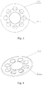
- Figure 2 is a schematic view of a structure of a filter component 106;
- Figure 3 is a schematic top view of the filter component 106 shown in Figure 2 ;
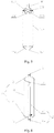
- Figure 4 is a schematic isometric view of the filter component 106 shown in Figure 2 .
- the filter component 106 mainly includes a filter screen 161 and a filter screen seat 162.
- Gas guide holes 163 are arranged on the filter screen seat 162.
- the filter screen 161 curves upwards to be in an arch shape.
- a center portion of the filter screen seat 162 also curves upwards to be in an arch shape.
- a diameter of the arch-shaped portion of the filter screen seat 162 is larger than a diameter of the outlet tube 102.
- the gas guide holes 163 are evenly arranged at a periphery of the arch-shaped area of the filter screen seat 162.
- a lower end of the outlet tube 102 is welded to the lower end cover 104, the outlet tube 102 is fixed connected to the lower end cover 104 by only a welding portion, and the outlet tube 102 is kept at a certain height inside the inner chamber of the cylindrical body 105 so as to be in a suspension state. Therefore, in the welding process, the outlet tube 102 is apt to incline. In addition, since the welding portion has a small size and is unable to subject a large force, damage is apt to happen when in use.
- a positioning device for fixing the outlet tube 102 is additionally provided for solving this problem.
- the positioning device includes a positioning sleeve 201 and a supporting frame 202, as shown in Figure 5 .
- a gas-liquid mixture enters into the inner chamber via the inlet tube 101.
- the gas after entering into the inner chamber, passes through the filter screen 161, and passes through the gas guide holes 163 into the inner chamber of the cylindrical body 5 under the blocking of the filter screen seat 162.
- the liquid of the gas-liquid mixture falls towards the bottom of the inner chamber of the cylindrical body 5 because of the pull of gravity.
- the gas floats and enters into the outlet tube 102 under the influence of an external force, and enters into the compressor after being exported from the outlet tube 102, and small portion of liquid flows out through an oil return hole of the outlet tube 102.
- Document JP-A-S62 131166 discloses a gas-liquid separator according to the preamble of claim1.
- the filter component in the gas-liquid separator has a relatively complicated structure, resulting in complicated assembling procedures and a high material cost. Therefore it is a technical problem to be solved presently by the skilled in the art to simplify the filter component, and reduce the manufacture cost of the gas-liquid separator.
- a gas-liquid separator is provided, which may be applied to a refrigerating system.
- a gas guide element of the gas-liquid separator has a simple structure, simple assembling procedures and a low material cost.
- a gas-liquid separator which includes a cylindrical body, an inlet tube fixedly connected to an upper end of the cylindrical body, and an outlet tube fixedly connected to a lower end of the cylindrical body, and further includes a gas guide element.
- the gas guide element further includes a baffle, a flange located at an end of the baffle and a bottom plate located at the other end of the baffle, the baffle is located above the outlet tube and adapted to shield a gas inlet of the outlet tube; the flange is fixedly connected to an inner wall of the cylindrical body; and the bottom plate is fixedly connected to a side wall of a gas inlet end of the outlet tube; the gas guide element further comprises vanes connected to both sides of the bottom plate respectively, and the vanes abut against the side wall of the gas inlet end of the outlet tube.
- the baffle is in a hemicycle shape, and the flange is located on an upper side of the baffle at a circular-arc end of the baffle, and the bottom plate is located on a lower side of the baffle at a straight line end of the baffle.
- the baffle is arranged to be inclined.
- the gas inlet end of the outlet tube is arranged to be an inclined plane facing the flange.
- a connecting surface is arranged at the side wall of the gas inlet end of the outlet tube, and the bottom plate is fixedly connected to the connecting surface by spot welding.
- the gas-liquid separator further includes a filter component, a through hole is provided at a side wall of a lower portion of the outlet tube, and the filter component is connected to the through hole.
- annular-shaped step is provided at an outer wall of the lower portion of the outlet tube, and an annular-shaped surface of the annular-shaped step is fixedly connected to the cylindrical body.
- the outlet tube includes a first straight tube located inside the inner chamber of the cylindrical body, and a second straight tube located outside the lower end of the cylindrical body, and both the first straight tube and the second straight tube are fixedly connected to the cylindrical body.
- the cylindrical body further includes an upper end cover, a lower end cover and an intermediate body fixedly connected to the upper end cover and the lower end cover, the inlet tube is fixedly connected to the upper end cover, the outlet tube is fixedly connected to the lower end cover, and the flange of the gas guide element is fixedly connected to an inner wall of the intermediate body.
- the filter component in the existing technology is replaced by a gas guide element including a baffle, a flange located at one end of the baffle and a bottom plate located at the other end of the baffle.
- the baffle is inclinedly arranged above the outlet tube, and shields a gas inlet of the outlet tube.
- the flange is fixedly connected to the inner wall of the cylindrical body.
- the bottom plate is fixedly connected to the side wall of the gas inlet end of the outlet tube.
- Liquid of the gas-liquid mixture falls towards the bottom of the inner chamber of the cylindrical body from up to down because of the pull of gravity.
- Gas of the gas-liquid mixture enters into the outlet tube under the action of an external force, and is exported to enter into a compressor via the outlet tube.
- the baffle of the gas guide element is arranged to be inclined and shields the gas inlet of the outlet tube, the flow rate of the gas-liquid mixture can be reduced when the gas-liquid mixture flows off, which avoids the impacting of the liquid to the gas inlet of the outlet tube, therefore prevents the liquid from directly falling into the outlet tube, and separate the gas-liquid mixture effectively.
- the gas guide element of the gas-liquid separator according to the present application may be made of a steel plate by simple manufacture procedures, which may not only separate the gas-liquid mixture effectively, and also reduce the manufacture cost.
- the gas guide element is fixedly connected to each of the cylinder body and the outlet tube, and also plays a role of fixing the outlet tube.
- the gas-liquid separator is particularly applicable to large and medium sized refrigerant system.
- the baffle is in a hemicycle shape
- the flange is arranged on an upper side of the baffle at a circular-arc end of the baffle
- the bottom plate is arranged a lower side of a straight line end of the baffle.
- the shape of the baffle matches with that of a cross section of the inner chamber of the cylindrical body.
- the vanes are connected at both sides of the bottom plate respectively; two vanes abut against the side wall of the gas inlet end of the outlet tube.
- the liquid rebounded by the inner wall of the cylinder body may be prevented from splashing into the outlet tube.
- a pre-fixing may be implemented by abutting the vanes of the gas guide element against the side wall of the gas inlet end of the outlet tube, thus simplifying the manufacture procedures.
- a gas-liquid separator is provided, applied to a refrigerating system, according to the present application.
- a gas guide element of the gas-liquid separator has a simple structure, simple assembling procedures and a low material cost.
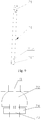
- Figure 6 is a schematic view showing a structure of a gas-liquid separator according to an embodiment of the present application
- Figure 7 is a schematic view showing a structure of a gas guide element according to an embodiment of the present application
- Figure 8 is an assembly drawing of the gas guide element shown in Figure 7 .
- a gas-liquid separator in an embodiment, includes a cylindrical body 5.
- the cylindrical body 5 includes an intermediate body 51 in a cylinder shape, an upper end cover 3, and a lower end cover 4, where the upper end cover 3 and the lower end cover 4 are fixedly connected to both ends of the intermediate body 51 respectively.
- the upper end cover 3, the intermediate body 51 and the lower end cover 4 constitute a closed inner chamber with a certain volume. No leakage or damage would happen when the inner chamber subjects a certain pressure.
- the gas-liquid separator may also have other structural forms.
- the gas-liquid separator further includes an inlet tube 1 arranged above the cylindrical body 5. A lower end of the inlet tube 1 is fixedly connected to the upper end cover 3.
- the gas-liquid separator further includes an outlet tube 2, and the outlet tube 2 is kept at a certain height inside the inner chamber of the cylindrical body 5. A lower end of the outlet tube 2 is fixedly connected to the lower end cover 4.
- a gas guide element 7 is arranged above the outlet tube 2.
- the gas guide element 7 includes a baffle 72, a flange 71 arranged at an upper side of an end of the baffle 72 and a bottom plate 73 arranged at a lower side of the other end of the baffle 72.
- the baffle 72 is located above the outlet tube 2 and adapted to shield a gas inlet of the outlet tube 2.
- the flange 71 is fixedly connected to an inner wall of the intermediate body 51.
- the bottom plate 73 is connected to a side wall of a gas inlet end of the outlet tube 2. It is to be noted that, the "shielding" means that a projection of the baffle 72 on a horizontal plane contains the gas inlet of the outlet tube 2.
- the outlet tube 2 is located between a plane on which the flange 71 is located and a plane on which the bottom plate 73 is located.
- the baffle 72 may be arranged to be inclined. When entering into the inner chamber of the cylindrical body 5 via the inlet tube 1, a gas-liquid mixture falls off on the baffle 72.
- the baffle 72 not only serves as a guiding, but also reduces the flow rate of the gas-liquid mixture.
- the baffle 72 shields the gas inlet of the outlet tube 2, it prevents the liquid from impacting the gas inlet of the outlet tube 2 directly; and effectively prevents the failure of the gas-liquid separation which results from the liquid entering into the outlet tube 2.
- the baffle 72 may be configured in a hemicycle shape, which matches with the shape of the cross section of the inner chamber of the cylindrical body 5. In this way, the scope of protection is effectively extended, and the liquid is prevented from entering into the outlet tube 2.
- the flange 71 is arranged on an upper side of the baffle 72 at a circular-arc end of the baffle 72, and the bottom plate 73 is arranged on a lower side of the baffle 72 at a straight line end of the baffle 72.
- the baffle 72 may also be arranged to have other shapes, such as a trapezoid shape.
- the flange 71 is arranged on an upper side of the baffle 72 at the upper end of the baffle 72, and the bottom plate 73 is arranged on a lower side the baffle at the lower end of the baffle.
- a connecting portion of the flange 71 connecting with the inner wall of the cylindrical body 5 is arranged to make a clearance between the edge of the baffle 72 and the inner wall of the cylindrical body 5 as small as possible, thus the scope protected by the baffle 72 may be extended as large as possible.
- the vanes 74 are provided at both sides of the bottom plate 73, and two vanes 74 abut against the side wall of the gas inlet end of the outlet tube 2. In this way, before the gas guide element 7 is welded to the outlet tube 2, a pre-fixing may be implemented by abutting the vanes 74 of the gas guide element 7 against the side wall of the gas inlet end of the outlet tube 2.
- a further function of the vane 74 is that the vanes 74 may block the liquid rebounded by the inner wall of the cylindrical body 5 when the liquid falls off. Thus, the failure of the gas-liquid separation may be prevented, which results from the liquid entering into the outlet tube 2 directly.
- a gas-liquid mixture firstly falls on the baffle 72 under the blocking of the gas guide element 7, and falls into the inner chamber of the cylindrical body 5 under the guiding of the baffle 72. Since the baffle 72 is arranged to be inclined, the flow rate of the gas-liquid mixture can be reduced. Liquid of the gas-liquid mixture falls towards the bottom of the inner chamber of the cylindrical body 5 from up to down because of the pull of gravity. Gas of the gas-liquid mixture enters into the outlet tube 2 under the action of an external force, and is exported to enter into a compressor via the outlet tube 2.
- the baffle 72 shields the gas inlet of the outlet tube 2, the shape of the baffle 72 matches with that of the cross section of the inner chamber of the cylindrical body 5, and also the bottom plate 73 and the vanes 74 closely abut against the outer wall of the gas inlet end of the outlet tube 2.
- the gas inlet of the outlet tube 2 by the fell liquid and splash the liquid into the outlet tube 2.
- the liquid rebounded by the inner wall of the cylindrical body 5 falls into the outlet tube 2, and the compressor slugging due to the fell liquid is further avoided.
- the gas guide element 7 may be made of a steel plate by simple manufacture procedures and simple assembling procedures, and thus the gas guide element 7 has a low manufacture cost.
- the gas guide element 7 may not only effectively separate the gas-liquid mixture, but also reduce the manufacture cost. Furthermore, the gas guide element 7 is fixedly connected with the cylindrical body 5 and the outlet tube 2, which is thus adapted to fix the outlet tube 2. Thus, the vibration of the outlet tube 2 during an operation as well as the noise due to the vibration is avoided. Therefore, the positioning device for positioning the outlet tube 2 may be removed, further reducing the manufacture cost.
- Figure 9 is a schematic view showing a structure of an outlet tube according to an embodiment of the present application
- Figure 10 is a schematic view showing a structure of a gas guide element according to another embodiment of the present application
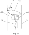
- Figure 11 is an assembly drawing of the gas guide element shown in Figure 10 .
- the baffle 72 shields the gas inlet of the outlet tube 1, though the baffle 72 is arranged to be inclined in a certain angle with the inlet plane of the outlet tube 1, it may still affect the discharge of the gas in a certain degree.
- the gas inlet end of the outlet tube 2 may be arranged to be an inclined plane facing the flange 71.
- the bottom plate 73 is fixedly connected to the outer wall at a higher portion of the gas inlet end of the outlet tube 2. The angle between the plane of the gas inlet of the outlet tube 2 and the baffle 72 increases, which facilitates the gas entering into the outlet tube 2.
- the vane 74 In the case that the gas inlet end of the outlet tube 2 is arranged to be an inclined plane, the vane 74 must be ensured to shield the inclined side wall of the gas inlet end of the outlet tube 2 in the arrangement, so as to prevent the liquid rebounded by the inner wall of the cylindrical body 5 from falling into the outlet tube 2.
- the side, fixedly connected to the bottom plate 73, of the gas inlet end of the outlet tube 2 may be arranged to be a connecting surface 211 (shown in Figure 9 ).
- the bottom plate 73 may be connected to the connecting surface 211 of the gas inlet end of the outlet tube 2 by spot welding (shown in Figure 11 ), to make the fixing between the gas guide element 7 and the outlet tube 2 more reliable.
- annular-shaped step 212 may be further arranged on an outer wall of a lower portion of the outlet tube 2. Specifically, the annular-shaped step 212 is located at the connecting portion of the lower end cover 4 and the outlet tube 2. An entire lower annular-shaped surface of the annular-shaped step 212 is fixedly connected to the inner wall of the lower end cover 4. In this way, the fixing area for fixing the outlet tube 2 may be increased to strengthen the fixing of the outlet tube 2.
- the lower annular-shaped surface of the annular-shaped step 211 means a step surface of the annular-shaped step 211 facing downwards when the annular-shaped step 211 is kept vertical.
- the outlet tube 2 may be divided into two parts in the manufacture, that is, a first straight tube 21 located inside the inner chamber of the cylindrical body 5 and a second straight tube 22 located outside the lower end of the cylindrical body 5. A lower end of the first straight tube 21 and an upper end of the second straight tube 22 are fixedly connected to the lower end cover 4.
- Other specific structural arrangements are the same as those of the above outlet tube 2 integrally manufactured, and the detail description thereof will be omitted.
- the fixed connection manner described hereinbefore may all be achieved by welding. Braze welding and argon arc welding may be chosen, and other welding method may also be adopted. Another fixed connection manners may also be chose.
- the gas-liquid separator may further include a filter component 6.
- the filter component 6 further includes a filter scat and a filter screen connected to the filter scat.
- a through hole is provided at a side wall of the outlet tube 2 at a lower portion of the inner chamber of the cylindrical body 5.
- the filter seat is fixedly connected to the through hole 213 (as shown in Figure 6 ). In this way, a small amount of liquid inside the inner chamber of the cylindrical body 5 may be exported to the outlet tube 2 via the filter component 6.
Landscapes
- Engineering & Computer Science (AREA)
- Chemical & Material Sciences (AREA)
- Chemical Kinetics & Catalysis (AREA)
- Analytical Chemistry (AREA)
- Power Engineering (AREA)
- Physics & Mathematics (AREA)
- Mechanical Engineering (AREA)
- Thermal Sciences (AREA)
- General Engineering & Computer Science (AREA)
- Separating Particles In Gases By Inertia (AREA)
- Filtering Of Dispersed Particles In Gases (AREA)
- Cyclones (AREA)
Description
- The present application relates to a gas-liquid separator, and particularly to a gas-liquid separator applied to a refrigerating system.
- A gas-liquid separator is generally applicable to a refrigerating system, which is mounted between an evaporator and a compressor. The gas-liquid separator is mainly adapted to separate a gas-phase refrigerant from a liquid-phase refrigerant, and only the gas-phase refrigerant is absorbed into the compressor from a suction port thereof. Thus, a compressor slugging may be avoided. In addition, refrigerant oil is returned into the compressor to lubricate the compressor, so as to ensure a normal operation of the compressor and store a part of the liquid-phase refrigerant.
- Referring to
Figure 1 , a schematic view of a conventional structure of a gas-liquid separator is shown. - The gas-liquid separator generally includes a
cylindrical body 105 with an inner chamber; anupper end cover 103 arranged above thecylindrical body 105 and fixedly connected with aninlet tube 101; and alower end cover 104 arranged below thecylindrical body 105 and fixedly connected with anoutlet tube 102. Theupper end cover 103, thecylindrical body 105 and thelower end cover 104 constitute a closed inner chamber with a certain volume. It is required that no leakage and no-damage would happen when the inner chamber subjects a certain pressure. Theoutlet tube 102 is kept at a certain height in the inner chamber. Theinlet tube 101 and theoutlet tube 102 arc coaxially arranged. Afilter component 106 is further arranged between an inner side of theupper end cover 103 and theoutlet tube 102. The gas-liquid separator may also have other structures. In a machine assembly, the outlet tube of the gas-liquid separator is kept vertically downwards, the inlet tube and the outlet tube are connected to tubes of the machine respectively, and the connected gas-liquid separator is located behind the evaporator and in front of the compressor. - Referring to
Figures 2 ,3 and4 ,Figure 2 is a schematic view of a structure of afilter component 106;Figure 3 is a schematic top view of thefilter component 106 shown inFigure 2 ; andFigure 4 is a schematic isometric view of thefilter component 106 shown inFigure 2 . Thefilter component 106 mainly includes afilter screen 161 and afilter screen seat 162.Gas guide holes 163 are arranged on thefilter screen seat 162. Thefilter screen 161 curves upwards to be in an arch shape. A center portion of thefilter screen seat 162 also curves upwards to be in an arch shape. A diameter of the arch-shaped portion of thefilter screen seat 162 is larger than a diameter of theoutlet tube 102. Thegas guide holes 163 are evenly arranged at a periphery of the arch-shaped area of thefilter screen seat 162. - A lower end of the
outlet tube 102 is welded to thelower end cover 104, theoutlet tube 102 is fixed connected to thelower end cover 104 by only a welding portion, and theoutlet tube 102 is kept at a certain height inside the inner chamber of thecylindrical body 105 so as to be in a suspension state. Therefore, in the welding process, theoutlet tube 102 is apt to incline. In addition, since the welding portion has a small size and is unable to subject a large force, damage is apt to happen when in use. In patentCN200520102760 outlet tube 102 is additionally provided for solving this problem. The positioning device includes apositioning sleeve 201 and a supportingframe 202, as shown inFigure 5 . - In an operation process, a gas-liquid mixture enters into the inner chamber via the
inlet tube 101. The gas, after entering into the inner chamber, passes through thefilter screen 161, and passes through thegas guide holes 163 into the inner chamber of thecylindrical body 5 under the blocking of thefilter screen seat 162. The liquid of the gas-liquid mixture falls towards the bottom of the inner chamber of thecylindrical body 5 because of the pull of gravity. The gas floats and enters into theoutlet tube 102 under the influence of an external force, and enters into the compressor after being exported from theoutlet tube 102, and small portion of liquid flows out through an oil return hole of theoutlet tube 102. DocumentJP-A-S62 131166 - Based on the above, the filter component in the gas-liquid separator has a relatively complicated structure, resulting in complicated assembling procedures and a high material cost. Therefore it is a technical problem to be solved presently by the skilled in the art to simplify the filter component, and reduce the manufacture cost of the gas-liquid separator.
- A gas-liquid separator is provided, which may be applied to a refrigerating system. A gas guide element of the gas-liquid separator has a simple structure, simple assembling procedures and a low material cost.
- To solve the above technical problem, a gas-liquid separator is provided according to claim 1, which includes a cylindrical body, an inlet tube fixedly connected to an upper end of the cylindrical body, and an outlet tube fixedly connected to a lower end of the cylindrical body, and further includes a gas guide element. The gas guide element further includes a baffle, a flange located at an end of the baffle and a bottom plate located at the other end of the baffle, the baffle is located above the outlet tube and adapted to shield a gas inlet of the outlet tube; the flange is fixedly connected to an inner wall of the cylindrical body; and the bottom plate is fixedly connected to a side wall of a gas inlet end of the outlet tube; the gas guide element further comprises vanes connected to both sides of the bottom plate respectively, and the vanes abut against the side wall of the gas inlet end of the outlet tube.
- Preferably, the baffle is in a hemicycle shape, and the flange is located on an upper side of the baffle at a circular-arc end of the baffle, and the bottom plate is located on a lower side of the baffle at a straight line end of the baffle.
- Preferably, the baffle is arranged to be inclined.
- Preferably, the gas inlet end of the outlet tube is arranged to be an inclined plane facing the flange.
- Preferably, a connecting surface is arranged at the side wall of the gas inlet end of the outlet tube, and the bottom plate is fixedly connected to the connecting surface by spot welding.
- Preferably, the gas-liquid separator further includes a filter component, a through hole is provided at a side wall of a lower portion of the outlet tube, and the filter component is connected to the through hole.
- Preferably, an annular-shaped step is provided at an outer wall of the lower portion of the outlet tube, and an annular-shaped surface of the annular-shaped step is fixedly connected to the cylindrical body.
- Preferably, the outlet tube includes a first straight tube located inside the inner chamber of the cylindrical body, and a second straight tube located outside the lower end of the cylindrical body, and both the first straight tube and the second straight tube are fixedly connected to the cylindrical body.
- Preferably, the cylindrical body further includes an upper end cover, a lower end cover and an intermediate body fixedly connected to the upper end cover and the lower end cover, the inlet tube is fixedly connected to the upper end cover, the outlet tube is fixedly connected to the lower end cover, and the flange of the gas guide element is fixedly connected to an inner wall of the intermediate body.
- According to the present application, the filter component in the existing technology is replaced by a gas guide element including a baffle, a flange located at one end of the baffle and a bottom plate located at the other end of the baffle. The baffle is inclinedly arranged above the outlet tube, and shields a gas inlet of the outlet tube. The flange is fixedly connected to the inner wall of the cylindrical body. The bottom plate is fixedly connected to the side wall of the gas inlet end of the outlet tube. In an operation process, after entering from the inlet tube, a gas-liquid mixture firstly falls on the baffle under the blocking of the gas guide element, and falls into the inner chamber of the cylindrical body under the guiding of the baffle. Liquid of the gas-liquid mixture falls towards the bottom of the inner chamber of the cylindrical body from up to down because of the pull of gravity. Gas of the gas-liquid mixture enters into the outlet tube under the action of an external force, and is exported to enter into a compressor via the outlet tube. Because the baffle of the gas guide element is arranged to be inclined and shields the gas inlet of the outlet tube, the flow rate of the gas-liquid mixture can be reduced when the gas-liquid mixture flows off, which avoids the impacting of the liquid to the gas inlet of the outlet tube, therefore prevents the liquid from directly falling into the outlet tube, and separate the gas-liquid mixture effectively. Compared with the existing technologies, the gas guide element of the gas-liquid separator according to the present application may be made of a steel plate by simple manufacture procedures, which may not only separate the gas-liquid mixture effectively, and also reduce the manufacture cost. The gas guide element is fixedly connected to each of the cylinder body and the outlet tube, and also plays a role of fixing the outlet tube. Thus, the positioning device for positioning the outlet tube is avoided, and the manufacture cost is further reduced. The gas-liquid separator is particularly applicable to large and medium sized refrigerant system.
- In a preferred embodiment, the baffle is in a hemicycle shape, the flange is arranged on an upper side of the baffle at a circular-arc end of the baffle, and the bottom plate is arranged a lower side of a straight line end of the baffle. The shape of the baffle matches with that of a cross section of the inner chamber of the cylindrical body. Thus, the scope protected by the baffle may extend and it may further be avoided to splash the liquid into the outlet tube during the falling of the liquid.
- The vanes are connected at both sides of the bottom plate respectively; two vanes abut against the side wall of the gas inlet end of the outlet tube. Thus, the liquid rebounded by the inner wall of the cylinder body may be prevented from splashing into the outlet tube. Besides, before the gas guide element is fixedly connected to the outlet tube, a pre-fixing may be implemented by abutting the vanes of the gas guide element against the side wall of the gas inlet end of the outlet tube, thus simplifying the manufacture procedures.
-
-
Figure 1 is a schematic view of a conventional structure of a gas-liquid separator; -
Figure 2 is a schematic view showing a structure of a filter component in the gas-liquid separator shown inFigure 1 ; -
Figure 3 is a schematic top view of the filter component shown inFigure 2 ; -
Figures 4 is a schematic axonometric view of the filter component shown inFigure 2 ; -
Figure 5 is a schematic view of another conventional structure of a gas-liquid separator; -
Figure 6 is a schematic view showing a structure of a gas-liquid separator according to an embodiment of the present application; -
Figure 7 is a schematic view showing a structure of a gas guide element according to an embodiment of the present application; -
Figure 8 is an assembly drawing of the gas guide element shown inFigure 7 ; -
Figure 9 is a schematic view showing a structure of a first straight tube according to an embodiment of the present application; -
Figure 10 is a schematic view showing a structure of a gas guide element according to another embodiment of the present application; and -
Figure 11 is an assembly drawing of the gas guide element shown inFigure 10 . - A gas-liquid separator is provided, applied to a refrigerating system, according to the present application. A gas guide element of the gas-liquid separator has a simple structure, simple assembling procedures and a low material cost.
- For those skilled in the art to better understand technical solutions of the present application, the present application is described in detail in conjunction with drawings and embodiments hereinafter.
- The locality terms such as "upper" and "lower" involved herein are all defined taken the orientation of an outlet tube of the gas-liquid separator to be vertical downwards as a reference, it is to be appreciated that, the employment of the locality terms should not limit the scope of protection claimed in the present application.
- Reference is made to
Figures 6 ,7 and8 .Figure 6 is a schematic view showing a structure of a gas-liquid separator according to an embodiment of the present application;Figure 7 is a schematic view showing a structure of a gas guide element according to an embodiment of the present application; andFigure 8 is an assembly drawing of the gas guide element shown inFigure 7 . - In an embodiment, a gas-liquid separator according to the present application includes a
cylindrical body 5. Thecylindrical body 5 includes anintermediate body 51 in a cylinder shape, anupper end cover 3, and alower end cover 4, where theupper end cover 3 and thelower end cover 4 are fixedly connected to both ends of theintermediate body 51 respectively. Theupper end cover 3, theintermediate body 51 and thelower end cover 4 constitute a closed inner chamber with a certain volume. No leakage or damage would happen when the inner chamber subjects a certain pressure. Apparently, the gas-liquid separator may also have other structural forms. - The gas-liquid separator further includes an inlet tube 1 arranged above the
cylindrical body 5. A lower end of the inlet tube 1 is fixedly connected to theupper end cover 3. - The gas-liquid separator further includes an outlet tube 2, and the outlet tube 2 is kept at a certain height inside the inner chamber of the
cylindrical body 5. A lower end of the outlet tube 2 is fixedly connected to thelower end cover 4. - A
gas guide element 7 is arranged above the outlet tube 2. Thegas guide element 7 includes abaffle 72, aflange 71 arranged at an upper side of an end of thebaffle 72 and abottom plate 73 arranged at a lower side of the other end of thebaffle 72. Thebaffle 72 is located above the outlet tube 2 and adapted to shield a gas inlet of the outlet tube 2. Theflange 71 is fixedly connected to an inner wall of theintermediate body 51. Thebottom plate 73 is connected to a side wall of a gas inlet end of the outlet tube 2. It is to be noted that, the "shielding" means that a projection of thebaffle 72 on a horizontal plane contains the gas inlet of the outlet tube 2. In this way, a location relationship between thebottom plate 73 and the outlet tube 2 is also further ensured. As illustrated inFigure 6 , the outlet tube 2 is located between a plane on which theflange 71 is located and a plane on which thebottom plate 73 is located. - The
baffle 72 may be arranged to be inclined. When entering into the inner chamber of thecylindrical body 5 via the inlet tube 1, a gas-liquid mixture falls off on thebaffle 72. Thus, thebaffle 72 not only serves as a guiding, but also reduces the flow rate of the gas-liquid mixture. In addition, since thebaffle 72 shields the gas inlet of the outlet tube 2, it prevents the liquid from impacting the gas inlet of the outlet tube 2 directly; and effectively prevents the failure of the gas-liquid separation which results from the liquid entering into the outlet tube 2. - In addition, the
baffle 72 may be configured in a hemicycle shape, which matches with the shape of the cross section of the inner chamber of thecylindrical body 5. In this way, the scope of protection is effectively extended, and the liquid is prevented from entering into the outlet tube 2. Here theflange 71 is arranged on an upper side of thebaffle 72 at a circular-arc end of thebaffle 72, and thebottom plate 73 is arranged on a lower side of thebaffle 72 at a straight line end of thebaffle 72. Thebaffle 72 may also be arranged to have other shapes, such as a trapezoid shape. In this case, theflange 71 is arranged on an upper side of thebaffle 72 at the upper end of thebaffle 72, and thebottom plate 73 is arranged on a lower side the baffle at the lower end of the baffle. In an arrangement, a connecting portion of theflange 71 connecting with the inner wall of thecylindrical body 5 is arranged to make a clearance between the edge of thebaffle 72 and the inner wall of thecylindrical body 5 as small as possible, thus the scope protected by thebaffle 72 may be extended as large as possible. - The
vanes 74 are provided at both sides of thebottom plate 73, and twovanes 74 abut against the side wall of the gas inlet end of the outlet tube 2. In this way, before thegas guide element 7 is welded to the outlet tube 2, a pre-fixing may be implemented by abutting thevanes 74 of thegas guide element 7 against the side wall of the gas inlet end of the outlet tube 2. A further function of thevane 74 is that thevanes 74 may block the liquid rebounded by the inner wall of thecylindrical body 5 when the liquid falls off. Thus, the failure of the gas-liquid separation may be prevented, which results from the liquid entering into the outlet tube 2 directly. - In the process of a normal operation of the whole system, after entering into the inner chamber of the
cylindrical body 5 via the inlet tube 1, a gas-liquid mixture firstly falls on thebaffle 72 under the blocking of thegas guide element 7, and falls into the inner chamber of thecylindrical body 5 under the guiding of thebaffle 72. Since thebaffle 72 is arranged to be inclined, the flow rate of the gas-liquid mixture can be reduced. Liquid of the gas-liquid mixture falls towards the bottom of the inner chamber of thecylindrical body 5 from up to down because of the pull of gravity. Gas of the gas-liquid mixture enters into the outlet tube 2 under the action of an external force, and is exported to enter into a compressor via the outlet tube 2. Thebaffle 72 shields the gas inlet of the outlet tube 2, the shape of thebaffle 72 matches with that of the cross section of the inner chamber of thecylindrical body 5, and also thebottom plate 73 and thevanes 74 closely abut against the outer wall of the gas inlet end of the outlet tube 2. Thus, it is effectively avoided to impact the gas inlet of the outlet tube 2 by the fell liquid and splash the liquid into the outlet tube 2. In addition, it is effectively avoided that the liquid rebounded by the inner wall of thecylindrical body 5 falls into the outlet tube 2, and the compressor slugging due to the fell liquid is further avoided. - The
gas guide element 7 may be made of a steel plate by simple manufacture procedures and simple assembling procedures, and thus thegas guide element 7 has a low manufacture cost. - Compared with the filter component in the existing technology, the
gas guide element 7 according to the present application may not only effectively separate the gas-liquid mixture, but also reduce the manufacture cost. Furthermore, thegas guide element 7 is fixedly connected with thecylindrical body 5 and the outlet tube 2, which is thus adapted to fix the outlet tube 2. Thus, the vibration of the outlet tube 2 during an operation as well as the noise due to the vibration is avoided. Therefore, the positioning device for positioning the outlet tube 2 may be removed, further reducing the manufacture cost. - Several improvements can be made to the
gas guide element 7 and the outlet tube 2 described hereinbefore. - Reference is made to
Figures 9, 10 and11 .Figure 9 is a schematic view showing a structure of an outlet tube according to an embodiment of the present application;Figure 10 is a schematic view showing a structure of a gas guide element according to another embodiment of the present application; andFigure 11 is an assembly drawing of the gas guide element shown inFigure 10 . - Since the
baffle 72 shields the gas inlet of the outlet tube 1, though thebaffle 72 is arranged to be inclined in a certain angle with the inlet plane of the outlet tube 1, it may still affect the discharge of the gas in a certain degree. For allowing the separated gas to enter into the outlet tube 2 smoothly under the action of an external force, the gas inlet end of the outlet tube 2 may be arranged to be an inclined plane facing theflange 71. In this way, thebottom plate 73 is fixedly connected to the outer wall at a higher portion of the gas inlet end of the outlet tube 2. The angle between the plane of the gas inlet of the outlet tube 2 and thebaffle 72 increases, which facilitates the gas entering into the outlet tube 2. - In the case that the gas inlet end of the outlet tube 2 is arranged to be an inclined plane, the
vane 74 must be ensured to shield the inclined side wall of the gas inlet end of the outlet tube 2 in the arrangement, so as to prevent the liquid rebounded by the inner wall of thecylindrical body 5 from falling into the outlet tube 2. - Further, in the case that the gas inlet end of the outlet tube 2 is arranged to be an inclined plane, the side, fixedly connected to the
bottom plate 73, of the gas inlet end of the outlet tube 2 may be arranged to be a connecting surface 211 (shown inFigure 9 ). Thebottom plate 73 may be connected to the connectingsurface 211 of the gas inlet end of the outlet tube 2 by spot welding (shown inFigure 11 ), to make the fixing between thegas guide element 7 and the outlet tube 2 more reliable. - For the reliable fixing of the outlet tube 2, an annular-shaped
step 212 may be further arranged on an outer wall of a lower portion of the outlet tube 2. Specifically, the annular-shapedstep 212 is located at the connecting portion of thelower end cover 4 and the outlet tube 2. An entire lower annular-shaped surface of the annular-shapedstep 212 is fixedly connected to the inner wall of thelower end cover 4. In this way, the fixing area for fixing the outlet tube 2 may be increased to strengthen the fixing of the outlet tube 2. It is to be noted that the lower annular-shaped surface of the annular-shapedstep 211 means a step surface of the annular-shapedstep 211 facing downwards when the annular-shapedstep 211 is kept vertical. - For facilitating the assembly, the outlet tube 2 may be divided into two parts in the manufacture, that is, a first
straight tube 21 located inside the inner chamber of thecylindrical body 5 and a secondstraight tube 22 located outside the lower end of thecylindrical body 5. A lower end of the firststraight tube 21 and an upper end of the secondstraight tube 22 are fixedly connected to thelower end cover 4. Other specific structural arrangements are the same as those of the above outlet tube 2 integrally manufactured, and the detail description thereof will be omitted. - It is to be noted that, the fixed connection manner described hereinbefore may all be achieved by welding. Braze welding and argon arc welding may be chosen, and other welding method may also be adopted. Another fixed connection manners may also be chose.
- Furthermore, the gas-liquid separator may further include a filter component 6. The filter component 6 further includes a filter scat and a filter screen connected to the filter scat. A through hole is provided at a side wall of the outlet tube 2 at a lower portion of the inner chamber of the
cylindrical body 5. The filter seat is fixedly connected to the through hole 213 (as shown inFigure 6 ). In this way, a small amount of liquid inside the inner chamber of thecylindrical body 5 may be exported to the outlet tube 2 via the filter component 6. - A gas-liquid separator according to the present application is described in detail hereinbefore. The principle and the embodiments of the present application are illustrated herein by specific examples. The above description of examples is only intended to help the understanding of the concept of the present application. It should be noted that, for the person skilled in the art, many modifications and improvements may be made to the present application without departing from the protection scope of the present application defined by the claims.
Claims (9)
- A gas-liquid separator, comprising a cylindrical body (5), an inlet tube (1) fixedly connected to an upper end of the cylindrical body (5), and an outlet tube (2) fixedly connected to a lower end of the cylindrical body (5), wherein
the gas-liquid separator further comprises a gas guide element (7), the gas guide element (7) comprises a baffle (72), characterised in that the gas guide element further comprises a flange (71) located at an end of the baffle (72), and a bottom plate (73) located at the other end of the baffle (72), the baffle (72) is located above the outlet tube (2) and adapted to shield a gas inlet of the outlet tube (2); the flange (71) is fixedly connected to an inner wall of the cylindrical body (5); and the bottom plate (73) is fixedly connected to a side wall of a gas inlet end of the outlet tube (2); vanes (74) connected to both sides of the bottom plate (73) respectively, and the vanes (74) abut against the side wall of the gas inlet end of the outlet tube (2). - The gas-liquid separator according to claim 1, wherein the baffle (72) is in a hemicycle shape, and the flange (71) is located on an upper side of the baffle (72) at a circular-arc end of the baffle (72), and the bottom plate (73) is located on a lower side of the baffle (72) at a straight line end of the baffle (72).
- The gas-liquid separator according to claim 1, wherein the baffle (72) is arranged to be inclined.
- The gas-liquid separator according to claim 3, wherein the gas inlet end of the outlet tube (2) is arranged to be an inclined plane facing the flange (71).
- The gas-liquid separator according to any one of claims 1 to 4, wherein a connecting surface (211) is arranged at the side wall of the gas inlet end of the outlet tube (2), and the bottom plate (73) is fixedly connected to the connecting surface (211) by spot welding.
- The gas-liquid separator according to any one of claims 1 to 4, wherein the gas-liquid separator further comprises a filter component (6), a through hole (213) is provided at a side wall of a lower portion of the outlet tube (2), and the filter component (6) is connected to the through hole (213).
- The gas-liquid separator according to any one of claims 1 to 4, wherein an annular-shaped step (211) is provided at an outer wall of a lower portion of the outlet tube (2), and an annular-shaped surface of the annular-shaped step (211) is fixedly connected to the cylindrical body (5).
- The gas-liquid separator according to any one of claims 1 to 4, wherein the outlet tube (2) comprises a first straight tube (21) located inside the inner chamber of the cylindrical body (5), and a second straight tube (22) located outside the lower end of the cylindrical body (5), and both the first straight tube (21) and the second straight tube (22) are fixedly connected to the cylindrical body (5).
- The gas-liquid separator according to any one of claims 1 to 4, wherein the cylindrical body (5) further comprises an upper end cover (3), a lower end cover (4) and an intermediate body (51) fixedly connected to the upper end cover (3) and the lower end cover (4), the inlet tube (1) is fixedly connected to the upper end cover (3), the outlet tube (2) is fixedly connected to the lower end cover (4), and the flange (71) of the gas guide element (7) is fixedly connected to an inner wall of the intermediate body (51).
Applications Claiming Priority (2)
| Application Number | Priority Date | Filing Date | Title |
|---|---|---|---|
| CN201210032480.0A CN103245143B (en) | 2012-02-14 | 2012-02-14 | Gas-liquid separator |
| PCT/CN2013/070926 WO2013120409A1 (en) | 2012-02-14 | 2013-01-24 | Gas-liquid separator |
Publications (3)
| Publication Number | Publication Date |
|---|---|
| EP2816300A1 EP2816300A1 (en) | 2014-12-24 |
| EP2816300A4 EP2816300A4 (en) | 2015-09-16 |
| EP2816300B1 true EP2816300B1 (en) | 2019-05-15 |
Family
ID=48924835
Family Applications (1)
| Application Number | Title | Priority Date | Filing Date |
|---|---|---|---|
| EP13749277.3A Active EP2816300B1 (en) | 2012-02-14 | 2013-01-24 | Gas-liquid separator |
Country Status (4)
| Country | Link |
|---|---|
| US (1) | US9696071B2 (en) |
| EP (1) | EP2816300B1 (en) |
| CN (1) | CN103245143B (en) |
| WO (1) | WO2013120409A1 (en) |
Families Citing this family (14)
| Publication number | Priority date | Publication date | Assignee | Title |
|---|---|---|---|---|
| CN104713277B (en) * | 2013-12-17 | 2017-12-05 | 浙江三花智能控制股份有限公司 | End-cap assembly and gas-liquid separator and its assembling equipment with the end-cap assembly |
| CN105737463B (en) * | 2014-12-08 | 2018-05-01 | 浙江三花智能控制股份有限公司 | A kind of liquid reservoir |
| CN106196769A (en) * | 2016-08-23 | 2016-12-07 | 郭继安 | Gas-liquid separator |
| CN106705467B (en) * | 2016-12-14 | 2022-11-25 | 山东超越地源热泵科技有限公司 | Transcritical CO2 heat pump heat supply system and heat supply method |
| CN107296565A (en) * | 2017-08-24 | 2017-10-27 | 苏州腾普电气科技有限公司 | The cleaning attachment of vacuum cleaner |
| CN109900026A (en) * | 2017-12-11 | 2019-06-18 | 浙江盾安机械有限公司 | Gas-liquid separator |
| EP3542693A1 (en) * | 2018-03-22 | 2019-09-25 | Hilti Aktiengesellschaft | Wet and/or dry vacuum cleaning unit |
| CN108426392A (en) * | 2018-05-05 | 2018-08-21 | 珠海格力电器股份有限公司 | Refrigerant purification device |
| DE102018214178A1 (en) | 2018-08-22 | 2020-02-27 | Hanon Systems | Accumulator, optionally in combination with an internal heat exchanger in a common housing, in particular for a motor vehicle air conditioning system |
| CN115479416B (en) * | 2021-06-16 | 2025-08-22 | 浙江盾安机械有限公司 | Gas-liquid separator and air conditioning equipment |
| CN114947641B (en) * | 2021-08-23 | 2023-05-09 | 苏州简单有为科技有限公司 | A surface cleaning device |
| CN114100305B (en) * | 2021-12-01 | 2024-05-31 | 天津双昊车用空调有限公司 | Processing technology of gas-liquid separator return pipeline |
| CN116440593B (en) * | 2023-04-14 | 2024-10-22 | 江苏科圣智能装备股份有限公司 | Silk screen demister for sulfuric acid pre-conversion waste heat boiler |
| US12274978B2 (en) * | 2023-07-11 | 2025-04-15 | Liquidat-R, LLC | Accumulator and dissipation assembly for capturing exigent vented volatile fluids |
Family Cites Families (35)
| Publication number | Priority date | Publication date | Assignee | Title |
|---|---|---|---|---|
| US2290323A (en) * | 1941-05-10 | 1942-07-21 | Clarence E Graham | Water and gas separator |
| US4036615A (en) * | 1975-09-15 | 1977-07-19 | Leo Heintzelman | Mist separator |
| JPS61197968A (en) * | 1985-02-28 | 1986-09-02 | 株式会社東芝 | Accumulator for compressor |
| JPS6263666U (en) * | 1985-10-11 | 1987-04-20 | ||
| JPS62131166A (en) * | 1985-12-04 | 1987-06-13 | 松下電器産業株式会社 | Accumulator |
| JPH0744237U (en) * | 1992-07-22 | 1995-11-07 | 三星電子株式会社 | Accumulator structure of air conditioner for both air conditioning and heating |
| US5904055A (en) * | 1995-09-19 | 1999-05-18 | Automotive Fluid Systems, Inc. | Accumulator deflector having a plastic bushing |
| US5787729A (en) * | 1997-06-04 | 1998-08-04 | Automotive Fluid Systems, Inc. | Accumulator deflector |
| US5868001A (en) * | 1997-12-05 | 1999-02-09 | Carrier Corporation | Suction accumulator with oil reservoir |
| US6178771B1 (en) * | 1999-03-29 | 2001-01-30 | Carrier Corporation | Suction accumulator |
| US6202437B1 (en) * | 1999-05-19 | 2001-03-20 | Carrier Corporation | Suction accumulator pre-charged with oil |
| US6223555B1 (en) * | 1999-06-08 | 2001-05-01 | Visteon Global Technologies, Inc. | Accumulator for an air conditioning system |
| US6419730B1 (en) * | 2000-08-28 | 2002-07-16 | Felix Chavez | Gas transmission system including a water separator |
| DE10058513A1 (en) * | 2000-11-24 | 2002-06-20 | Obrist Engineering Gmbh Lusten | collector |
| DE10125404A1 (en) * | 2001-05-25 | 2002-11-28 | Mann & Hummel Filter | Inertial separator for cleaning gas stream has pattern of curved blades to bend gas stream and with sloping collecting surface for impurities |
| JP3929899B2 (en) * | 2001-09-06 | 2007-06-13 | 株式会社セイワ・プロ | Cleaning system for drain pipes in mobile equipment |
| US6564575B1 (en) | 2001-10-30 | 2003-05-20 | Visteon Global Technologies, Inc. | Accumulator with inlet port comprising a deflector |
| US6568204B2 (en) | 2001-10-30 | 2003-05-27 | Automotive Fluid Systems, Inc. | Baffle connection for an accumulator and related method of manufacturing |
| US20040118148A1 (en) * | 2002-12-24 | 2004-06-24 | Ti Group Automotives Systems, Llc | Accumulator with inlet diffuser\diverter |
| KR100548436B1 (en) * | 2003-03-05 | 2006-02-02 | 엘지전자 주식회사 | Accumulators in Hermetic Compressors |
| JP2004279006A (en) * | 2003-03-19 | 2004-10-07 | Fujitsu General Ltd | Air conditioner |
| WO2005023396A1 (en) * | 2003-09-09 | 2005-03-17 | Shell Internationale Research Maatschappij B.V. | Gas/liquid separator |
| JP4118254B2 (en) * | 2004-06-18 | 2008-07-16 | 三洋電機株式会社 | Refrigeration equipment |
| US7461519B2 (en) * | 2005-02-03 | 2008-12-09 | Halla Climate Control Canada, Inc. | Accumulator with deflector |
| KR100667877B1 (en) * | 2005-10-10 | 2007-01-16 | 삼성광주전자 주식회사 | Multi Cyclone Dust Collector |
| DE102005059482A1 (en) * | 2005-12-07 | 2007-06-14 | Visteon Global Technologies, Inc., Van Buren | Refrigerant accumulator with liquid separator |
| US20080016887A1 (en) * | 2006-04-19 | 2008-01-24 | Locke Marcos A | Pressure balancing accumulator |
| DE102006022024A1 (en) | 2006-05-10 | 2007-11-15 | Behr Gmbh & Co. Kg | Air conditioning system`s accumulator for use in motor vehicle, has pipe with refrigerant-inlet-sided end by which gaseous refrigerant is reached into pipe, where end is arranged in increased area |
| MY155337A (en) * | 2008-06-30 | 2015-10-05 | Amt Int Inc | Wet-gas separator |
| US20100132317A1 (en) * | 2008-11-21 | 2010-06-03 | Thien J Philip | Dust separator |
| US8105022B2 (en) * | 2009-03-30 | 2012-01-31 | Ge-Hitachi Nuclear Energy Americas Llc | Vane configurations for steam dryers |
| US7785400B1 (en) * | 2009-06-30 | 2010-08-31 | Sand Separators LLC | Spherical sand separators |
| FI122330B (en) * | 2010-04-09 | 2011-12-15 | Runtech Systems Oy | Apparatus for water separation in a paper machine's vacuum system and method using the same |
| CN101852522B (en) * | 2010-06-07 | 2015-10-14 | 浙江三花制冷集团有限公司 | A kind of vapour liquid separator |
| IN2015KN00248A (en) * | 2012-07-31 | 2015-06-12 | Suncoke Technology & Dev Llc |
-
2012
- 2012-02-14 CN CN201210032480.0A patent/CN103245143B/en active Active
-
2013
- 2013-01-24 WO PCT/CN2013/070926 patent/WO2013120409A1/en not_active Ceased
- 2013-01-24 EP EP13749277.3A patent/EP2816300B1/en active Active
- 2013-01-24 US US14/363,371 patent/US9696071B2/en active Active
Non-Patent Citations (1)
| Title |
|---|
| None * |
Also Published As
| Publication number | Publication date |
|---|---|
| US9696071B2 (en) | 2017-07-04 |
| EP2816300A1 (en) | 2014-12-24 |
| CN103245143A (en) | 2013-08-14 |
| CN103245143B (en) | 2016-09-21 |
| US20140352270A1 (en) | 2014-12-04 |
| EP2816300A4 (en) | 2015-09-16 |
| WO2013120409A1 (en) | 2013-08-22 |
Similar Documents
| Publication | Publication Date | Title |
|---|---|---|
| US9696071B2 (en) | Gas-liquid separator | |
| JP5632963B2 (en) | Refrigeration compressor suction mechanism | |
| US7716946B2 (en) | Accumulator with deflector | |
| CN101440809B (en) | Liquid container for horizontal compressor and control method and application thereof | |
| EP2012021B1 (en) | Liquid tank | |
| CN102230704B (en) | Centrifugal oil-gas separator | |
| CN111578564A (en) | Gas-liquid separation device | |
| JP6055291B2 (en) | accumulator | |
| CN106196769A (en) | Gas-liquid separator | |
| CN115479418B (en) | Gas-liquid separator for automobile air conditioner thermal management system | |
| CN205373179U (en) | Oil separator and compression cycle system | |
| CN107677019B (en) | Vapor-liquid separator and compressor | |
| CN103851846A (en) | Oil separator and air conditioner system comprising oil separator | |
| US6125652A (en) | Apparatus for minimizing refrigerant usage | |
| US20060196219A1 (en) | Accumulator with full-flow filtering | |
| CN204943983U (en) | A kind of gas-liquid separator | |
| CN116117433A (en) | A new type of liquid accumulator, its production process and a compressor with the liquid accumulator | |
| CN114234497B (en) | Liquid storage device and compressor assembly | |
| EP1225403B1 (en) | Accumulator-dehydrator assembly | |
| JP2022049194A (en) | Oil separation element, oil separator and compression system | |
| JP2006214700A (en) | accumulator | |
| CN210602365U (en) | Gas-liquid separator and compressor | |
| CN118980203B (en) | Dispenser assembly, rotary compressor and air conditioner | |
| CN206709456U (en) | Gas-liquid separator and air conditioner | |
| US20240053069A1 (en) | Accumulator for compressor |
Legal Events
| Date | Code | Title | Description |
|---|---|---|---|
| PUAI | Public reference made under article 153(3) epc to a published international application that has entered the european phase |
Free format text: ORIGINAL CODE: 0009012 |
|
| 17P | Request for examination filed |
Effective date: 20140620 |
|
| AK | Designated contracting states |
Kind code of ref document: A1 Designated state(s): AL AT BE BG CH CY CZ DE DK EE ES FI FR GB GR HR HU IE IS IT LI LT LU LV MC MK MT NL NO PL PT RO RS SE SI SK SM TR |
|
| AX | Request for extension of the european patent |
Extension state: BA ME |
|
| DAX | Request for extension of the european patent (deleted) | ||
| RA4 | Supplementary search report drawn up and despatched (corrected) |
Effective date: 20150818 |
|
| RIC1 | Information provided on ipc code assigned before grant |
Ipc: F25B 43/00 20060101AFI20150812BHEP |
|
| RAP1 | Party data changed (applicant data changed or rights of an application transferred) |
Owner name: ZHEJIANG SANHUA INTELLIGENT CONTROLS CO., LTD. |
|
| GRAP | Despatch of communication of intention to grant a patent |
Free format text: ORIGINAL CODE: EPIDOSNIGR1 |
|
| STAA | Information on the status of an ep patent application or granted ep patent |
Free format text: STATUS: GRANT OF PATENT IS INTENDED |
|
| INTG | Intention to grant announced |
Effective date: 20181123 |
|
| GRAS | Grant fee paid |
Free format text: ORIGINAL CODE: EPIDOSNIGR3 |
|
| GRAA | (expected) grant |
Free format text: ORIGINAL CODE: 0009210 |
|
| STAA | Information on the status of an ep patent application or granted ep patent |
Free format text: STATUS: THE PATENT HAS BEEN GRANTED |
|
| AK | Designated contracting states |
Kind code of ref document: B1 Designated state(s): AL AT BE BG CH CY CZ DE DK EE ES FI FR GB GR HR HU IE IS IT LI LT LU LV MC MK MT NL NO PL PT RO RS SE SI SK SM TR |
|
| REG | Reference to a national code |
Ref country code: CH Ref legal event code: EP Ref country code: GB Ref legal event code: FG4D |
|
| REG | Reference to a national code |
Ref country code: DE Ref legal event code: R096 Ref document number: 602013055432 Country of ref document: DE |
|
| REG | Reference to a national code |
Ref country code: IE Ref legal event code: FG4D |
|
| REG | Reference to a national code |
Ref country code: NL Ref legal event code: MP Effective date: 20190515 |
|
| REG | Reference to a national code |
Ref country code: LT Ref legal event code: MG4D |
|
| PG25 | Lapsed in a contracting state [announced via postgrant information from national office to epo] |
Ref country code: AL Free format text: LAPSE BECAUSE OF FAILURE TO SUBMIT A TRANSLATION OF THE DESCRIPTION OR TO PAY THE FEE WITHIN THE PRESCRIBED TIME-LIMIT Effective date: 20190515 Ref country code: PT Free format text: LAPSE BECAUSE OF FAILURE TO SUBMIT A TRANSLATION OF THE DESCRIPTION OR TO PAY THE FEE WITHIN THE PRESCRIBED TIME-LIMIT Effective date: 20190915 Ref country code: ES Free format text: LAPSE BECAUSE OF FAILURE TO SUBMIT A TRANSLATION OF THE DESCRIPTION OR TO PAY THE FEE WITHIN THE PRESCRIBED TIME-LIMIT Effective date: 20190515 Ref country code: NL Free format text: LAPSE BECAUSE OF FAILURE TO SUBMIT A TRANSLATION OF THE DESCRIPTION OR TO PAY THE FEE WITHIN THE PRESCRIBED TIME-LIMIT Effective date: 20190515 Ref country code: NO Free format text: LAPSE BECAUSE OF FAILURE TO SUBMIT A TRANSLATION OF THE DESCRIPTION OR TO PAY THE FEE WITHIN THE PRESCRIBED TIME-LIMIT Effective date: 20190815 Ref country code: LT Free format text: LAPSE BECAUSE OF FAILURE TO SUBMIT A TRANSLATION OF THE DESCRIPTION OR TO PAY THE FEE WITHIN THE PRESCRIBED TIME-LIMIT Effective date: 20190515 Ref country code: FI Free format text: LAPSE BECAUSE OF FAILURE TO SUBMIT A TRANSLATION OF THE DESCRIPTION OR TO PAY THE FEE WITHIN THE PRESCRIBED TIME-LIMIT Effective date: 20190515 Ref country code: SE Free format text: LAPSE BECAUSE OF FAILURE TO SUBMIT A TRANSLATION OF THE DESCRIPTION OR TO PAY THE FEE WITHIN THE PRESCRIBED TIME-LIMIT Effective date: 20190515 Ref country code: HR Free format text: LAPSE BECAUSE OF FAILURE TO SUBMIT A TRANSLATION OF THE DESCRIPTION OR TO PAY THE FEE WITHIN THE PRESCRIBED TIME-LIMIT Effective date: 20190515 |
|
| PG25 | Lapsed in a contracting state [announced via postgrant information from national office to epo] |
Ref country code: RS Free format text: LAPSE BECAUSE OF FAILURE TO SUBMIT A TRANSLATION OF THE DESCRIPTION OR TO PAY THE FEE WITHIN THE PRESCRIBED TIME-LIMIT Effective date: 20190515 Ref country code: LV Free format text: LAPSE BECAUSE OF FAILURE TO SUBMIT A TRANSLATION OF THE DESCRIPTION OR TO PAY THE FEE WITHIN THE PRESCRIBED TIME-LIMIT Effective date: 20190515 Ref country code: GR Free format text: LAPSE BECAUSE OF FAILURE TO SUBMIT A TRANSLATION OF THE DESCRIPTION OR TO PAY THE FEE WITHIN THE PRESCRIBED TIME-LIMIT Effective date: 20190816 Ref country code: BG Free format text: LAPSE BECAUSE OF FAILURE TO SUBMIT A TRANSLATION OF THE DESCRIPTION OR TO PAY THE FEE WITHIN THE PRESCRIBED TIME-LIMIT Effective date: 20190815 |
|
| REG | Reference to a national code |
Ref country code: AT Ref legal event code: MK05 Ref document number: 1133918 Country of ref document: AT Kind code of ref document: T Effective date: 20190515 |
|
| PG25 | Lapsed in a contracting state [announced via postgrant information from national office to epo] |
Ref country code: AT Free format text: LAPSE BECAUSE OF FAILURE TO SUBMIT A TRANSLATION OF THE DESCRIPTION OR TO PAY THE FEE WITHIN THE PRESCRIBED TIME-LIMIT Effective date: 20190515 Ref country code: RO Free format text: LAPSE BECAUSE OF FAILURE TO SUBMIT A TRANSLATION OF THE DESCRIPTION OR TO PAY THE FEE WITHIN THE PRESCRIBED TIME-LIMIT Effective date: 20190515 Ref country code: CZ Free format text: LAPSE BECAUSE OF FAILURE TO SUBMIT A TRANSLATION OF THE DESCRIPTION OR TO PAY THE FEE WITHIN THE PRESCRIBED TIME-LIMIT Effective date: 20190515 Ref country code: SK Free format text: LAPSE BECAUSE OF FAILURE TO SUBMIT A TRANSLATION OF THE DESCRIPTION OR TO PAY THE FEE WITHIN THE PRESCRIBED TIME-LIMIT Effective date: 20190515 Ref country code: EE Free format text: LAPSE BECAUSE OF FAILURE TO SUBMIT A TRANSLATION OF THE DESCRIPTION OR TO PAY THE FEE WITHIN THE PRESCRIBED TIME-LIMIT Effective date: 20190515 Ref country code: DK Free format text: LAPSE BECAUSE OF FAILURE TO SUBMIT A TRANSLATION OF THE DESCRIPTION OR TO PAY THE FEE WITHIN THE PRESCRIBED TIME-LIMIT Effective date: 20190515 |
|
| REG | Reference to a national code |
Ref country code: DE Ref legal event code: R097 Ref document number: 602013055432 Country of ref document: DE |
|
| PG25 | Lapsed in a contracting state [announced via postgrant information from national office to epo] |
Ref country code: SM Free format text: LAPSE BECAUSE OF FAILURE TO SUBMIT A TRANSLATION OF THE DESCRIPTION OR TO PAY THE FEE WITHIN THE PRESCRIBED TIME-LIMIT Effective date: 20190515 Ref country code: IT Free format text: LAPSE BECAUSE OF FAILURE TO SUBMIT A TRANSLATION OF THE DESCRIPTION OR TO PAY THE FEE WITHIN THE PRESCRIBED TIME-LIMIT Effective date: 20190515 |
|
| PLBE | No opposition filed within time limit |
Free format text: ORIGINAL CODE: 0009261 |
|
| STAA | Information on the status of an ep patent application or granted ep patent |
Free format text: STATUS: NO OPPOSITION FILED WITHIN TIME LIMIT |
|
| PG25 | Lapsed in a contracting state [announced via postgrant information from national office to epo] |
Ref country code: TR Free format text: LAPSE BECAUSE OF FAILURE TO SUBMIT A TRANSLATION OF THE DESCRIPTION OR TO PAY THE FEE WITHIN THE PRESCRIBED TIME-LIMIT Effective date: 20190515 |
|
| 26N | No opposition filed |
Effective date: 20200218 |
|
| PG25 | Lapsed in a contracting state [announced via postgrant information from national office to epo] |
Ref country code: PL Free format text: LAPSE BECAUSE OF FAILURE TO SUBMIT A TRANSLATION OF THE DESCRIPTION OR TO PAY THE FEE WITHIN THE PRESCRIBED TIME-LIMIT Effective date: 20190515 |
|
| PG25 | Lapsed in a contracting state [announced via postgrant information from national office to epo] |
Ref country code: SI Free format text: LAPSE BECAUSE OF FAILURE TO SUBMIT A TRANSLATION OF THE DESCRIPTION OR TO PAY THE FEE WITHIN THE PRESCRIBED TIME-LIMIT Effective date: 20190515 |
|
| PG25 | Lapsed in a contracting state [announced via postgrant information from national office to epo] |
Ref country code: MC Free format text: LAPSE BECAUSE OF FAILURE TO SUBMIT A TRANSLATION OF THE DESCRIPTION OR TO PAY THE FEE WITHIN THE PRESCRIBED TIME-LIMIT Effective date: 20190515 |
|
| REG | Reference to a national code |
Ref country code: CH Ref legal event code: PL |
|
| GBPC | Gb: european patent ceased through non-payment of renewal fee |
Effective date: 20200124 |
|
| REG | Reference to a national code |
Ref country code: BE Ref legal event code: MM Effective date: 20200131 |
|
| PG25 | Lapsed in a contracting state [announced via postgrant information from national office to epo] |
Ref country code: LU Free format text: LAPSE BECAUSE OF NON-PAYMENT OF DUE FEES Effective date: 20200124 Ref country code: GB Free format text: LAPSE BECAUSE OF NON-PAYMENT OF DUE FEES Effective date: 20200124 |
|
| PG25 | Lapsed in a contracting state [announced via postgrant information from national office to epo] |
Ref country code: BE Free format text: LAPSE BECAUSE OF NON-PAYMENT OF DUE FEES Effective date: 20200131 Ref country code: CH Free format text: LAPSE BECAUSE OF NON-PAYMENT OF DUE FEES Effective date: 20200131 Ref country code: LI Free format text: LAPSE BECAUSE OF NON-PAYMENT OF DUE FEES Effective date: 20200131 |
|
| PG25 | Lapsed in a contracting state [announced via postgrant information from national office to epo] |
Ref country code: IE Free format text: LAPSE BECAUSE OF NON-PAYMENT OF DUE FEES Effective date: 20200124 |
|
| PG25 | Lapsed in a contracting state [announced via postgrant information from national office to epo] |
Ref country code: MT Free format text: LAPSE BECAUSE OF FAILURE TO SUBMIT A TRANSLATION OF THE DESCRIPTION OR TO PAY THE FEE WITHIN THE PRESCRIBED TIME-LIMIT Effective date: 20190515 Ref country code: CY Free format text: LAPSE BECAUSE OF FAILURE TO SUBMIT A TRANSLATION OF THE DESCRIPTION OR TO PAY THE FEE WITHIN THE PRESCRIBED TIME-LIMIT Effective date: 20190515 |
|
| PG25 | Lapsed in a contracting state [announced via postgrant information from national office to epo] |
Ref country code: MK Free format text: LAPSE BECAUSE OF FAILURE TO SUBMIT A TRANSLATION OF THE DESCRIPTION OR TO PAY THE FEE WITHIN THE PRESCRIBED TIME-LIMIT Effective date: 20190515 Ref country code: IS Free format text: LAPSE BECAUSE OF FAILURE TO SUBMIT A TRANSLATION OF THE DESCRIPTION OR TO PAY THE FEE WITHIN THE PRESCRIBED TIME-LIMIT Effective date: 20190915 |
|
| P01 | Opt-out of the competence of the unified patent court (upc) registered |
Effective date: 20230530 |
|
| PGFP | Annual fee paid to national office [announced via postgrant information from national office to epo] |
Ref country code: DE Payment date: 20260114 Year of fee payment: 14 |
|
| PGFP | Annual fee paid to national office [announced via postgrant information from national office to epo] |
Ref country code: FR Payment date: 20260128 Year of fee payment: 14 |