EP2816251A1 - Frein pour roue d'aéronef, en particulier pour un hélicoptère. - Google Patents
Frein pour roue d'aéronef, en particulier pour un hélicoptère. Download PDFInfo
- Publication number
- EP2816251A1 EP2816251A1 EP14172454.2A EP14172454A EP2816251A1 EP 2816251 A1 EP2816251 A1 EP 2816251A1 EP 14172454 A EP14172454 A EP 14172454A EP 2816251 A1 EP2816251 A1 EP 2816251A1
- Authority
- EP
- European Patent Office
- Prior art keywords
- jaw
- wafer
- brake
- fixed plate
- protrusion
- Prior art date
- Legal status (The legal status is an assumption and is not a legal conclusion. Google has not performed a legal analysis and makes no representation as to the accuracy of the status listed.)
- Granted
Links
Images


Classifications
-
- F—MECHANICAL ENGINEERING; LIGHTING; HEATING; WEAPONS; BLASTING
- F16—ENGINEERING ELEMENTS AND UNITS; GENERAL MEASURES FOR PRODUCING AND MAINTAINING EFFECTIVE FUNCTIONING OF MACHINES OR INSTALLATIONS; THERMAL INSULATION IN GENERAL
- F16D—COUPLINGS FOR TRANSMITTING ROTATION; CLUTCHES; BRAKES
- F16D55/00—Brakes with substantially-radial braking surfaces pressed together in axial direction, e.g. disc brakes
- F16D55/02—Brakes with substantially-radial braking surfaces pressed together in axial direction, e.g. disc brakes with axially-movable discs or pads pressed against axially-located rotating members
- F16D55/22—Brakes with substantially-radial braking surfaces pressed together in axial direction, e.g. disc brakes with axially-movable discs or pads pressed against axially-located rotating members by clamping an axially-located rotating disc between movable braking members, e.g. movable brake discs or brake pads
- F16D55/224—Brakes with substantially-radial braking surfaces pressed together in axial direction, e.g. disc brakes with axially-movable discs or pads pressed against axially-located rotating members by clamping an axially-located rotating disc between movable braking members, e.g. movable brake discs or brake pads with a common actuating member for the braking members
- F16D55/225—Brakes with substantially-radial braking surfaces pressed together in axial direction, e.g. disc brakes with axially-movable discs or pads pressed against axially-located rotating members by clamping an axially-located rotating disc between movable braking members, e.g. movable brake discs or brake pads with a common actuating member for the braking members the braking members being brake pads
- F16D55/226—Brakes with substantially-radial braking surfaces pressed together in axial direction, e.g. disc brakes with axially-movable discs or pads pressed against axially-located rotating members by clamping an axially-located rotating disc between movable braking members, e.g. movable brake discs or brake pads with a common actuating member for the braking members the braking members being brake pads in which the common actuating member is moved axially, e.g. floating caliper disc brakes
-
- F—MECHANICAL ENGINEERING; LIGHTING; HEATING; WEAPONS; BLASTING
- F16—ENGINEERING ELEMENTS AND UNITS; GENERAL MEASURES FOR PRODUCING AND MAINTAINING EFFECTIVE FUNCTIONING OF MACHINES OR INSTALLATIONS; THERMAL INSULATION IN GENERAL
- F16D—COUPLINGS FOR TRANSMITTING ROTATION; CLUTCHES; BRAKES
- F16D65/00—Parts or details
- F16D65/02—Braking members; Mounting thereof
- F16D65/04—Bands, shoes or pads; Pivots or supporting members therefor
- F16D65/092—Bands, shoes or pads; Pivots or supporting members therefor for axially-engaging brakes, e.g. disc brakes
- F16D65/095—Pivots or supporting members therefor
-
- B—PERFORMING OPERATIONS; TRANSPORTING
- B64—AIRCRAFT; AVIATION; COSMONAUTICS
- B64C—AEROPLANES; HELICOPTERS
- B64C25/00—Alighting gear
- B64C25/32—Alighting gear characterised by elements which contact the ground or similar surface
- B64C25/42—Arrangement or adaptation of brakes
- B64C25/44—Actuating mechanisms
-
- F—MECHANICAL ENGINEERING; LIGHTING; HEATING; WEAPONS; BLASTING
- F16—ENGINEERING ELEMENTS AND UNITS; GENERAL MEASURES FOR PRODUCING AND MAINTAINING EFFECTIVE FUNCTIONING OF MACHINES OR INSTALLATIONS; THERMAL INSULATION IN GENERAL
- F16D—COUPLINGS FOR TRANSMITTING ROTATION; CLUTCHES; BRAKES
- F16D65/00—Parts or details
- F16D65/02—Braking members; Mounting thereof
- F16D65/04—Bands, shoes or pads; Pivots or supporting members therefor
- F16D65/092—Bands, shoes or pads; Pivots or supporting members therefor for axially-engaging brakes, e.g. disc brakes
-
- F—MECHANICAL ENGINEERING; LIGHTING; HEATING; WEAPONS; BLASTING
- F16—ENGINEERING ELEMENTS AND UNITS; GENERAL MEASURES FOR PRODUCING AND MAINTAINING EFFECTIVE FUNCTIONING OF MACHINES OR INSTALLATIONS; THERMAL INSULATION IN GENERAL
- F16D—COUPLINGS FOR TRANSMITTING ROTATION; CLUTCHES; BRAKES
- F16D69/00—Friction linings; Attachment thereof; Selection of coacting friction substances or surfaces
- F16D69/04—Attachment of linings
- F16D69/0408—Attachment of linings specially adapted for plane linings
-
- F—MECHANICAL ENGINEERING; LIGHTING; HEATING; WEAPONS; BLASTING
- F16—ENGINEERING ELEMENTS AND UNITS; GENERAL MEASURES FOR PRODUCING AND MAINTAINING EFFECTIVE FUNCTIONING OF MACHINES OR INSTALLATIONS; THERMAL INSULATION IN GENERAL
- F16D—COUPLINGS FOR TRANSMITTING ROTATION; CLUTCHES; BRAKES
- F16D55/00—Brakes with substantially-radial braking surfaces pressed together in axial direction, e.g. disc brakes
- F16D2055/0004—Parts or details of disc brakes
- F16D2055/005—Brakes straddling an annular brake disc radially internally
-
- F—MECHANICAL ENGINEERING; LIGHTING; HEATING; WEAPONS; BLASTING
- F16—ENGINEERING ELEMENTS AND UNITS; GENERAL MEASURES FOR PRODUCING AND MAINTAINING EFFECTIVE FUNCTIONING OF MACHINES OR INSTALLATIONS; THERMAL INSULATION IN GENERAL
- F16D—COUPLINGS FOR TRANSMITTING ROTATION; CLUTCHES; BRAKES
- F16D55/00—Brakes with substantially-radial braking surfaces pressed together in axial direction, e.g. disc brakes
- F16D2055/0075—Constructional features of axially engaged brakes
- F16D2055/0083—Constructional features of axially engaged brakes with brake actuator located radially inside of an annular rotor
-
- F—MECHANICAL ENGINEERING; LIGHTING; HEATING; WEAPONS; BLASTING
- F16—ENGINEERING ELEMENTS AND UNITS; GENERAL MEASURES FOR PRODUCING AND MAINTAINING EFFECTIVE FUNCTIONING OF MACHINES OR INSTALLATIONS; THERMAL INSULATION IN GENERAL
- F16D—COUPLINGS FOR TRANSMITTING ROTATION; CLUTCHES; BRAKES
- F16D69/00—Friction linings; Attachment thereof; Selection of coacting friction substances or surfaces
- F16D69/04—Attachment of linings
- F16D2069/0425—Attachment methods or devices
- F16D2069/0433—Connecting elements not integral with the braking member, e.g. bolts, rivets
-
- F—MECHANICAL ENGINEERING; LIGHTING; HEATING; WEAPONS; BLASTING
- F16—ENGINEERING ELEMENTS AND UNITS; GENERAL MEASURES FOR PRODUCING AND MAINTAINING EFFECTIVE FUNCTIONING OF MACHINES OR INSTALLATIONS; THERMAL INSULATION IN GENERAL
- F16D—COUPLINGS FOR TRANSMITTING ROTATION; CLUTCHES; BRAKES
- F16D69/00—Friction linings; Attachment thereof; Selection of coacting friction substances or surfaces
- F16D69/04—Attachment of linings
- F16D2069/0425—Attachment methods or devices
- F16D2069/0441—Mechanical interlocking, e.g. roughened lining carrier, mating profiles on friction material and lining carrier
Definitions
- the invention relates to an aircraft wheel brake, in particular for a helicopter.
- brakes comprising a stack of disks of which one half are stators, and the other half are rotors which rotate with the wheel.
- Braking actuators allow pressing the discs against each other to generate a braking torque opposing the free rotation of the wheel on its axle.
- the object of the invention is to propose a stirrup brake which is mounted on the inside of the disc, adapted to the use of discs of reduced diameter.
- an aircraft wheel brake comprising on the one hand a stirrup with an outer jaw receiving a fixed plate and an inner jaw which is movable under the action of an actuator. braking and which receives a movable plate, and secondly a disc which extends between the pads and which comprises means for its rotation in solidarity with the wheel.
- at least one of the wafers comprises a protrusion projecting from a rear face of the wafer to be received in a corresponding receptacle of the associated jaw ensuring both the positioning of the wafer on the jaw. and transmitting braking forces from the fixed wafer to the associated jaw.
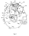
- the brake 100 of the invention is intended to be installed on an aircraft undercarriage which can be seen the lower arm 1 which carries an axle 2.
- the axle 2 is provided with a flange 3 on which the brake is attached to the by means of two bolts 4.
- the brake 100 comprises a stirrup 101 provided with two lugs 102 enabling the brake to be attached to the collar 3.
- the stirrup 101 comprises an outer jaw 103 and a support 104 which receives a braking actuator 105, here an electromechanical actuator, which is attached to the support 104 by means of screws 106.
- the braking actuator 105 comprises a pusher at the end of which a movable inner jaw (not visible) receives a movable plate 107 which is pushed by the pusher to approach a fixed plate 108 carried by the outer jaw 103.
- a disk 109 extends between the platelets 107, 108 so as to be clamped between the platelets under the action of the actuator 105.
- the disc comprises tenons 110 which are received in suitable mortises of the rim of the wheel to be secured in rotation thereof, while being free to move axially. The disc is thus mounted "floating".
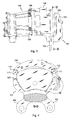
- the plates 107, 108 are of identical shapes and comprise shims 111 which project laterally from the wafers to be received in corresponding housings 112 of the associated jaw (visible in FIG. figure 4 ).
- the lateral braking forces are transmitted by the shims 111 of the mobile plate 107 to the support 104, so that the actuator 105 undergoes only the axial braking forces.
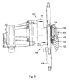
- the outer jaw 103 receives a central pin 120 which extends halfway between the outer jaw 103 and the fixed plate 108.
- the braking forces are transmitted by the central pin 120 of the fixed plate 108 to the outer jaw 103.
- the central pin 120 forms a protrusion protruding from a rear face of the wafer 108 to be received in a receptacle 123, here directly made in the outer jaw 103.
- the central pin 120 is equipped with a centering shank 121 which extends into an orifice opening from the outer jaw 103 to project outwardly from the latter, which allows the visual verification of the presence of the central pin 120.
- a clip 122 extends between the fixed plate 108 and central pin 120 to secure these two elements together.
- the central pin 120 and the fixed plate 108 have recesses facing to receive said staple 122.
- the fixed plate 108 also includes shims 111, not useful here.
- the lateral size of the outer jaw 103 is limited to what is strictly necessary, which makes it possible to pass it through the central orifice of a disc of smaller size than that of the discs usually used with this type of brake.
- the plates 207, 208 both have central protrusions 215, 216 made integrally with the wafer and which project from the rear faces of the wafers to be received in receptacles 217, 218 made respectively in the outer jaw 203 and in the inner jaw 210.
- the fixed plate 208 is secured to the outer jaw 203 by means of a bolt 219, while the plate mobile 207 is secured to the inner jaw 210 by means of a staple 220.
Landscapes
- Engineering & Computer Science (AREA)
- General Engineering & Computer Science (AREA)
- Mechanical Engineering (AREA)
- Aviation & Aerospace Engineering (AREA)
- Braking Arrangements (AREA)
Abstract
Description
- L'invention concerne un frein pour roue d'aéronef, en particulier pour un hélicoptère.
- Sur les aéronefs d'une certaine taille, on utilise généralement des freins comportant une pile de disques dont une moitié sont des stators, et l'autre moitié sont des rotors qui tournent avec la roue. Des actionneurs de freinage permettent de presser les disques les uns contre les autres pour engendrer un couple de freinage s'opposant à la libre rotation de la roue sur son essieu.
- Pour des aéronefs plus petits, il est connu d'utiliser un frein à un seul disque tournant avec la roue, le disque étant associé à un étrier qui vient chevaucher le disque et dont les mors reçoivent deux plaquettes, dont une est montée mobile pour pouvoir pincer le disque entre les deux plaquettes au moyen d'un actionneur de freinage. Pour minimiser l'encombrement du frein, l'étrier est placé à cheval sur le disque par l'intérieur de celui-ci. Cependant, dans ce type de frein, les plaquettes sont tenues sur les deux mors de l'étrier par leurs extrémités, ce qui impose une certaine dimension transversale du mors qui passe à l'intérieur du disque lors du montage du frein. Cependant, dans des applications particulièrement exigeantes où le diamètre de l'orifice central du disque est petit, cet encombrement transversal rend difficile le montage du frein, ou oblige à utiliser des plaquettes de surface réduite.
- L'invention a pour objet de proposer un frein à étrier qui se monte par l'intérieur du disque, adapté à l'utilisation de disques de diamètre réduit.
- En vue de la réalisation de ce but, on propose un frein pour roue d'aéronef, comportant d'une part un étrier avec un mors externe recevant une plaquette fixe et un mors interne qui est mobile sous l'action d'un actionneur de freinage et qui reçoit une plaquette mobile, et d'autre part un disque qui s'étend entre les plaquettes et qui comporte des moyens de sa solidarisation en rotation avec la roue. Selon l'invention, au moins l'une des plaquettes comporte une protrusion s'étendant en saillie d'une face arrière de la plaquette pour être reçue dans un réceptacle conforme du mors associé assurant à la fois le positionnement de la plaquette sur le mors et la transmission des efforts de freinage de la plaquette fixe au mors associé.
- Ainsi, il devient possible de limiter l'encombrement transversal de la plaquette fixe et du mors associé, tout en assurant le positionnement de la plaquette et la transmission des efforts de freinage. On peut dès lors utiliser l'étrier avec des disques plus petits, tout en permettant le passage du mors externe par l'intérieur du disque.
- L'invention sera mieux comprise à la lumière de la description qui suit d'un mode particulier de réalisation de l'invention, en référence aux figures des dessins annexés parmi lesquelles :
- la
figure 1 est une vue en perspective d'un frein avec son étrier et son disque en place sur un at-terrisseur d'hélicoptère, vue du côté du disque, la roue n'ayant pas été représentée pour plus de clarté ; - la
figure 2 est une vue en perspective du frein de lafigure 1 vu de l'arrière ; - la
figure 3 est une vue de côté de l'étrier de lafigure 1 ; - la
figure 4 est une vue de face de l'étrier de lafigure 1 avec coupe selon la ligne D-D de lafigure 3 ; - la
figure 5 est une vue de côté du frein de lafigure 1 avec une coupe partielle au niveau de la plaquette fixe ; - la
figure 6 est une vue analogue à celle de lafigure 5 d'un deuxième mode particulier de réalisation de l'invention. - En référence aux
figures 1 à 4 , le frein 100 de l'invention est destiné à être installé sur un atterrisseur d'aéronef dont on aperçoit le bras inférieur 1 qui porte un essieu 2. L'essieu 2 est pourvu d'une collerette 3 sur lequel le frein est rapporté au moyen de deux boulons 4. - Le frein 100 comporte un étrier 101 muni de deux oreilles 102 permettant la fixation du frein à la collerette 3. L'étrier 101 comporte un mors externe 103 et un support 104 qui reçoit un actionneur de freinage 105, ici un actionneur électromécanique, qui est rapporté sur le support 104 au moyen de vis 106.
- L'actionneur de freinage 105 comporte un poussoir au bout duquel un mors interne mobile (non visible) reçoit une plaquette mobile 107 qui est poussée par le poussoir pour se rapprocher d'une plaquette fixe 108 portée par le mors externe 103. Un disque 109 s'étend entre les plaquettes 107, 108 de façon à pouvoir être pincé entre les plaquettes sous l'action de l'actionneur 105. Le disque comporte des tenons 110 qui sont reçus dans des mortaises conformes de la jante de la roue pour être solidaire en rotation de celle-ci, tout en étant libre de se déplacer axialement. Le disque est ainsi monté « flottant ».
- Ici, les plaquettes 107, 108 sont de formes identiques et comportent des cales 111 qui saillent latéralement des plaquettes pour être reçues dans des logements correspondants 112 du mors associé (visibles à la
figure 4 ). Les efforts latéraux de freinage sont transmis par les cales 111 de la plaquette mobile 107 au support 104, de sorte que l'actionneur 105 ne subit que les efforts axiaux de freinage. - Selon l'invention, et ainsi que cela est plus spécifiquement visible à la
figure 5 , le mors externe 103 reçoit un pion central 120 qui s'étend à mi-chair entre le mors externe 103 et la plaquette fixe 108. Les efforts de freinage sont transmis par le pion central 120 de la plaquette fixe 108 au mors externe 103. Le pion central 120 forme une protrusion saillant d'une face arrière de la plaquette 108 pour être reçue dans un réceptacle 123, ici directement réalisé dans le mors externe 103. - Le pion central 120 est équipé d'une queue de centrage 121 qui s'étend dans un orifice débouchant du mors externe 103 pour saillir extérieurement de celui-ci, ce qui permet la vérification visuelle de la présence du pion central 120.
- En outre, une agrafe 122 s'étend entre la plaquette fixe 108 et pion central 120 pour solidariser ces deux éléments entre eux. A cet effet, le pion central 120 et la plaquette fixe 108 présentent des évidements en regard pour recevoir ladite agrafe 122. Comme les plaquettes 107, 108 sont identiques, on aperçoit sur la
figure 4 l'évidemment en question sur la plaquette mobile 107. On note que la plaquette fixe 108 comporte également des cales 111, sans utilité ici. - L'utilisation d'un pion central 120 pour la transmission des efforts entre la plaquette fixe 108 et le mors externe 103 permet de diminuer l'encombrement latéral du mors externe 103, puisque celui-ci n'a plus besoin de présenter des extensions latérales dans lesquelles seraient ménagés des logements 112 propres à recevoir les cales 107. Ainsi, et comme cela est visible à la
figure 1 , le contour externe du mors externe 103 peut suivre exactement le contour externe de la plaquette fixe 108, afin d'offrir à celle-ci une surface de réaction suffisante, tout en limitant l'encombrement latéral du mors extérieur 103. On voit d'ailleurs les cales 111 de la plaquette fixe 108 dépasser (légèrement) du mors externe 103. - De la sorte, l'encombrement latéral du mors externe 103 est limité au strict nécessaire, ce qui permet de le faire passer dans l'orifice central d'un disque de taille plus petite que celle des disques habituellement utilisés avec ce genre de freins.
- Pour le démontage d'un tel frein, on commence par enlever la roue, puis on desserre les boulons 4 qui retiennent l'étrier sur l'atterrisseur. On enlève en bloc l'étrier et le disque 109, puis une fois l'ensemble éloigné de l'atterrisseur, on sépare le disque de l'étrier en faisant passer le mors externe 103 par l'orifice central du disque 109. La limitation de l'encombrement latéral du mors externe 103 permet de la faire passer dans un orifice central réduit.
- Selon un deuxième mode de réalisation illustré à la
figure 6 , sur laquelle les références des éléments identiques ont été augmentées d'une centaine, les plaquettes 207, 208 présentent toutes deux des protrusions centrales 215, 216 réalisées intégralement avec la plaquette et qui s'étendent en saillie des faces arrières des plaquettes pour être reçues dans des réceptacles 217, 218 réalisés respectivement dans le mors externe 203 et dans le mors interne 210. - La plaquette fixe 208 est solidarisée sur le mors externe 203 au moyen d'un boulon 219, tandis que la plaquette mobile 207 est solidarisée sur le mors interne 210 au moyen d'une agrafe 220.
- Ainsi, pour les deux plaquettes, les efforts latéraux sont transmis par les protrusions, de sorte que des cales latérales sont inutiles.
Claims (7)
- Frein pour roue d'aéronef, comportant d'une part un étrier avec un mors externe (103 ; 203) recevant une plaquette fixe (108 ; 208) et un mors interne qui est mobile (210) sous l'action d'un actionneur de freinage (105 ; 205) et qui reçoit une plaquette mobile (107), et d'autre part un disque (109 ; 209) qui s'étend entre les plaquettes et qui comporte des moyens de sa solidarisation en rotation (110) avec la roue , caractérisé en ce qu'au moins l'une des plaquettes comporte une protrusion (120 ; 215 ; 216) s'étendant en saillie d'une face arrière de la plaquette pour être reçue dans un réceptacle conforme (123 ; 217 ; 218) du mors associé assurant à la fois le positionnement de la plaquette sur le mors et la transmission des efforts de freinage de la plaquette fixe au mors associé.
- Frein selon la revendication 1, dans lequel le réceptacle est réalisé directement dans le mors.
- Frein selon la revendication 1, dans lequel la protrusion (215 ; 216) est réalisée intégralement avec la plaquette (208, 207).
- Frein selon la revendication 1, dans lequel la protrusion (120) est réalisée au moyen d'un pion central (120) reçu dans un logement débouchant sur la face arrière de la plaquette pour saillir de celle-ci et s'étendre à mi-chair dans le mors et dans la plaquette.
- Frein selon la revendication 4 dans lequel le pion central (120) comporte une queue de centrage (121) qui s'étend dans un orifice débouchant du mors externe (103) pour saillir extérieurement de celui-ci.
- Frein selon la revendication 4, dans lequel le pion central (120) et la plaquette fixe (108) sont solidarisés entre eux au moyen d'une agrafe (122).
- Frein selon la revendication 4, dans lequel la plaquette fixe (108) et le mors externe (103) ont des contours externes sensiblement identiques.
Applications Claiming Priority (1)
| Application Number | Priority Date | Filing Date | Title |
|---|---|---|---|
| FR1355666A FR3007096B1 (fr) | 2013-06-17 | 2013-06-17 | Frein pour roue d'aeronef, en particulier pour un helicoptere. |
Publications (2)
| Publication Number | Publication Date |
|---|---|
| EP2816251A1 true EP2816251A1 (fr) | 2014-12-24 |
| EP2816251B1 EP2816251B1 (fr) | 2020-06-03 |
Family
ID=49003905
Family Applications (1)
| Application Number | Title | Priority Date | Filing Date |
|---|---|---|---|
| EP14172454.2A Active EP2816251B1 (fr) | 2013-06-17 | 2014-06-13 | Frein pour roue d'aéronef, en particulier pour un hélicoptère. |
Country Status (3)
| Country | Link |
|---|---|
| US (1) | US20140367209A1 (fr) |
| EP (1) | EP2816251B1 (fr) |
| FR (1) | FR3007096B1 (fr) |
Families Citing this family (6)
| Publication number | Priority date | Publication date | Assignee | Title |
|---|---|---|---|---|
| IL241966B (en) | 2015-10-08 | 2019-11-28 | Israel Aerospace Ind Ltd | An electric brake is added for aircraft |
| FR3082255B1 (fr) | 2018-06-12 | 2020-05-22 | Airbus Helicopters | Systeme de freinage a disque et aeronef |
| FR3082256B1 (fr) | 2018-06-12 | 2020-05-29 | Airbus Helicopters | Systeme de freinage pour un train d'atterrissage d'aeronef a etrier avec plusieurs zone de pincement du disque de frein |
| FR3094430B1 (fr) | 2019-03-28 | 2021-04-02 | Airbus Helicopters | Disque de frein, système de freinage à disque et véhicule |
| FR3102963B1 (fr) | 2019-11-07 | 2021-11-12 | Safran Landing Systems | Procédé de freinage d’aéronef, comprenant une correction dynamique de la commande de freinage |
| CN111853103B (zh) * | 2020-07-24 | 2025-03-07 | 重庆朗正科技有限公司 | 机轮刹车系统 |
Citations (4)
| Publication number | Priority date | Publication date | Assignee | Title |
|---|---|---|---|---|
| US2586518A (en) * | 1948-09-11 | 1952-02-19 | Wingfoot Corp | Mechanical aircraft brake |
| US3170543A (en) * | 1962-12-06 | 1965-02-23 | Goodyear Tire & Rubber | Delay valve |
| US4433757A (en) * | 1982-03-01 | 1984-02-28 | General Motors Corporation | Disc brake lining retainer and wear warning arrangement |
| US20040211630A1 (en) * | 2000-07-31 | 2004-10-28 | Wilfried Strauss | Disc brake |
Family Cites Families (9)
| Publication number | Priority date | Publication date | Assignee | Title |
|---|---|---|---|---|
| DE2313693A1 (de) * | 1973-03-20 | 1974-10-10 | Teves Gmbh Alfred | Teilbelagscheibenbremse |
| DE2313692A1 (de) * | 1973-03-20 | 1974-10-10 | Teves Gmbh Alfred | Teilbelagscheibenbremse |
| US4146118A (en) * | 1978-02-14 | 1979-03-27 | Zankl Robert H | Brake shoe assembly |
| DE4136107A1 (de) * | 1991-11-02 | 1993-05-06 | Alfred Teves Gmbh, 6000 Frankfurt, De | Bremsklotz mit verdrehgesicherter haltefeder |
| US5429215A (en) * | 1993-08-13 | 1995-07-04 | King; E. Autry | Quick change brake shoe with removable brake shoe pads |
| JP3722450B2 (ja) * | 1996-03-25 | 2005-11-30 | 曙ブレーキ工業株式会社 | ディスクブレーキ用摩擦パッド |
| US6125973A (en) * | 1998-12-29 | 2000-10-03 | Irvine; Mark W. | Brake pad holder |
| US6913120B2 (en) * | 2003-01-15 | 2005-07-05 | Anstro Manufacturing, Inc. | Method of securing a shim to a backing plate and subassembly formed thereby |
| DE102008019003A1 (de) * | 2008-04-14 | 2009-10-15 | Tmd Friction Services Gmbh | Bremsbelag mit Adapter für Scheibenbremsen |
-
2013
- 2013-06-17 FR FR1355666A patent/FR3007096B1/fr not_active Expired - Fee Related
-
2014
- 2014-06-13 EP EP14172454.2A patent/EP2816251B1/fr active Active
- 2014-06-16 US US14/305,929 patent/US20140367209A1/en not_active Abandoned
Patent Citations (4)
| Publication number | Priority date | Publication date | Assignee | Title |
|---|---|---|---|---|
| US2586518A (en) * | 1948-09-11 | 1952-02-19 | Wingfoot Corp | Mechanical aircraft brake |
| US3170543A (en) * | 1962-12-06 | 1965-02-23 | Goodyear Tire & Rubber | Delay valve |
| US4433757A (en) * | 1982-03-01 | 1984-02-28 | General Motors Corporation | Disc brake lining retainer and wear warning arrangement |
| US20040211630A1 (en) * | 2000-07-31 | 2004-10-28 | Wilfried Strauss | Disc brake |
Also Published As
| Publication number | Publication date |
|---|---|
| FR3007096B1 (fr) | 2016-09-23 |
| FR3007096A1 (fr) | 2014-12-19 |
| US20140367209A1 (en) | 2014-12-18 |
| EP2816251B1 (fr) | 2020-06-03 |
Similar Documents
| Publication | Publication Date | Title |
|---|---|---|
| EP2816251B1 (fr) | Frein pour roue d'aéronef, en particulier pour un hélicoptère. | |
| EP1496601B1 (fr) | Système de freinage à reprise de couple sécurisée | |
| EP3253984B1 (fr) | Frein à disque comportant au moins un ressort de rappel élastique d'un patin de freinage, ressort de rappel élastique, et kit de remplacement | |
| EP3006763B1 (fr) | Ressort de rappel élastique d'un patin de freinage comportant des moyens de rattrapage du jeu d'usure, frein à disque et kit de remplacement | |
| EP2876326B1 (fr) | Procédé de rénovation et d'utilisation de disques de frein de type stator arrière à plots, disque assemblé et pile de disques correspondante | |
| EP3015368A1 (fr) | Dispositif de fixation d'un moteur d'aéronef, et aéronef correspondant | |
| EP3642091B1 (fr) | Système de freinage ferroviaire pour véhicule ferroviaire | |
| FR3093321A1 (fr) | Roue d’aéronef pourvue d’écrans thermiques | |
| EP0196966B1 (fr) | Butée de débrayage, notamment pour véhicule automobile | |
| FR2895467A1 (fr) | Agencement pour l'assemblage de deux pieces par vissage par l'intermediaire d'un ensemble vis-ecrou | |
| FR2538483A1 (fr) | Frein a disque et a pince coulissante | |
| EP3581822B1 (fr) | Systeme de freinage pour un train d'atterrissage d'aeronef a etrier avec plusieurs zones de pincement du disque de frein | |
| EP1437521A1 (fr) | Dispositif de fixation d'un étrier de frein à disque sur une fusée d'essieu, notamment pour véhicule automobile | |
| FR2478246A1 (fr) | Manille, et suspension comportant une telle manille, notamment pour ligne aerienne a conducteurs isoles | |
| EP0246144B1 (fr) | Dispositif de marquage pour outil à manche plat et notamment pour clé ou analogue | |
| EP2873611B1 (fr) | Roue d'aéronef équipée de moyens de son entraînement en rotation par un actionneur d'entraînement | |
| EP2239358B1 (fr) | Dispositif d'assemblage, ensemble de deux pièces assemblées par un tel dispositif et lame de machine de formation de la foule comprenant un tel ensemble | |
| EP2873610B1 (fr) | Roue d'aéronef équipée d'une couronne d'entraînement à chaîne | |
| EP2221494A1 (fr) | Dispositif de fixation d'un palier radial d'un arbre de transmission d'un véhicule | |
| WO2023139341A1 (fr) | Système de freinage ferroviaire pour véhicule ferroviaire, à freins à au moins un sabot, et véhicule ferroviaire pourvu d'un tel système | |
| EP3521117B1 (fr) | Actionneur electromecanique de frein de vehicule, comprenant une region de rupture mecanique | |
| FR3060874A1 (fr) | Cosse de raccordement a une batterie | |
| WO2017203139A1 (fr) | Système de support d'un carter structural de turbomachine et ensemble de liaison associé | |
| FR2976038A1 (fr) | Dispositif de freinage a etrier flottant avec montage radial direct ou indirect de l'etrier | |
| FR2528139A1 (fr) | Dispositif amortisseur de torsion, en particulier friction d'embrayage pour vehicule automobile |
Legal Events
| Date | Code | Title | Description |
|---|---|---|---|
| PUAI | Public reference made under article 153(3) epc to a published international application that has entered the european phase |
Free format text: ORIGINAL CODE: 0009012 |
|
| 17P | Request for examination filed |
Effective date: 20140613 |
|
| AK | Designated contracting states |
Kind code of ref document: A1 Designated state(s): AL AT BE BG CH CY CZ DE DK EE ES FI FR GB GR HR HU IE IS IT LI LT LU LV MC MK MT NL NO PL PT RO RS SE SI SK SM TR |
|
| AX | Request for extension of the european patent |
Extension state: BA ME |
|
| R17P | Request for examination filed (corrected) |
Effective date: 20150623 |
|
| RBV | Designated contracting states (corrected) |
Designated state(s): AL AT BE BG CH CY CZ DE DK EE ES FI FR GB GR HR HU IE IS IT LI LT LU LV MC MK MT NL NO PL PT RO RS SE SI SK SM TR |
|
| RAP1 | Party data changed (applicant data changed or rights of an application transferred) |
Owner name: SAFRAN LANDING SYSTEMS |
|
| RAP1 | Party data changed (applicant data changed or rights of an application transferred) |
Owner name: SAFRAN LANDING SYSTEMS |
|
| GRAP | Despatch of communication of intention to grant a patent |
Free format text: ORIGINAL CODE: EPIDOSNIGR1 |
|
| STAA | Information on the status of an ep patent application or granted ep patent |
Free format text: STATUS: GRANT OF PATENT IS INTENDED |
|
| RIC1 | Information provided on ipc code assigned before grant |
Ipc: F16D 69/04 20060101ALI20191127BHEP Ipc: F16D 55/226 20060101AFI20191127BHEP Ipc: F16D 65/092 20060101ALI20191127BHEP |
|
| INTG | Intention to grant announced |
Effective date: 20191217 |
|
| GRAS | Grant fee paid |
Free format text: ORIGINAL CODE: EPIDOSNIGR3 |
|
| GRAA | (expected) grant |
Free format text: ORIGINAL CODE: 0009210 |
|
| STAA | Information on the status of an ep patent application or granted ep patent |
Free format text: STATUS: THE PATENT HAS BEEN GRANTED |
|
| AK | Designated contracting states |
Kind code of ref document: B1 Designated state(s): AL AT BE BG CH CY CZ DE DK EE ES FI FR GB GR HR HU IE IS IT LI LT LU LV MC MK MT NL NO PL PT RO RS SE SI SK SM TR |
|
| REG | Reference to a national code |
Ref country code: GB Ref legal event code: FG4D Free format text: NOT ENGLISH |
|
| REG | Reference to a national code |
Ref country code: AT Ref legal event code: REF Ref document number: 1277320 Country of ref document: AT Kind code of ref document: T Effective date: 20200615 Ref country code: CH Ref legal event code: EP |
|
| REG | Reference to a national code |
Ref country code: DE Ref legal event code: R096 Ref document number: 602014066133 Country of ref document: DE |
|
| REG | Reference to a national code |
Ref country code: LT Ref legal event code: MG4D |
|
| PG25 | Lapsed in a contracting state [announced via postgrant information from national office to epo] |
Ref country code: NO Free format text: LAPSE BECAUSE OF FAILURE TO SUBMIT A TRANSLATION OF THE DESCRIPTION OR TO PAY THE FEE WITHIN THE PRESCRIBED TIME-LIMIT Effective date: 20200903 Ref country code: SE Free format text: LAPSE BECAUSE OF FAILURE TO SUBMIT A TRANSLATION OF THE DESCRIPTION OR TO PAY THE FEE WITHIN THE PRESCRIBED TIME-LIMIT Effective date: 20200603 Ref country code: LT Free format text: LAPSE BECAUSE OF FAILURE TO SUBMIT A TRANSLATION OF THE DESCRIPTION OR TO PAY THE FEE WITHIN THE PRESCRIBED TIME-LIMIT Effective date: 20200603 Ref country code: FI Free format text: LAPSE BECAUSE OF FAILURE TO SUBMIT A TRANSLATION OF THE DESCRIPTION OR TO PAY THE FEE WITHIN THE PRESCRIBED TIME-LIMIT Effective date: 20200603 Ref country code: GR Free format text: LAPSE BECAUSE OF FAILURE TO SUBMIT A TRANSLATION OF THE DESCRIPTION OR TO PAY THE FEE WITHIN THE PRESCRIBED TIME-LIMIT Effective date: 20200904 |
|
| REG | Reference to a national code |
Ref country code: NL Ref legal event code: MP Effective date: 20200603 |
|
| PG25 | Lapsed in a contracting state [announced via postgrant information from national office to epo] |
Ref country code: LV Free format text: LAPSE BECAUSE OF FAILURE TO SUBMIT A TRANSLATION OF THE DESCRIPTION OR TO PAY THE FEE WITHIN THE PRESCRIBED TIME-LIMIT Effective date: 20200603 Ref country code: BG Free format text: LAPSE BECAUSE OF FAILURE TO SUBMIT A TRANSLATION OF THE DESCRIPTION OR TO PAY THE FEE WITHIN THE PRESCRIBED TIME-LIMIT Effective date: 20200903 Ref country code: RS Free format text: LAPSE BECAUSE OF FAILURE TO SUBMIT A TRANSLATION OF THE DESCRIPTION OR TO PAY THE FEE WITHIN THE PRESCRIBED TIME-LIMIT Effective date: 20200603 Ref country code: HR Free format text: LAPSE BECAUSE OF FAILURE TO SUBMIT A TRANSLATION OF THE DESCRIPTION OR TO PAY THE FEE WITHIN THE PRESCRIBED TIME-LIMIT Effective date: 20200603 |
|
| REG | Reference to a national code |
Ref country code: AT Ref legal event code: MK05 Ref document number: 1277320 Country of ref document: AT Kind code of ref document: T Effective date: 20200603 |
|
| PG25 | Lapsed in a contracting state [announced via postgrant information from national office to epo] |
Ref country code: AL Free format text: LAPSE BECAUSE OF FAILURE TO SUBMIT A TRANSLATION OF THE DESCRIPTION OR TO PAY THE FEE WITHIN THE PRESCRIBED TIME-LIMIT Effective date: 20200603 Ref country code: NL Free format text: LAPSE BECAUSE OF FAILURE TO SUBMIT A TRANSLATION OF THE DESCRIPTION OR TO PAY THE FEE WITHIN THE PRESCRIBED TIME-LIMIT Effective date: 20200603 |
|
| PG25 | Lapsed in a contracting state [announced via postgrant information from national office to epo] |
Ref country code: RO Free format text: LAPSE BECAUSE OF FAILURE TO SUBMIT A TRANSLATION OF THE DESCRIPTION OR TO PAY THE FEE WITHIN THE PRESCRIBED TIME-LIMIT Effective date: 20200603 Ref country code: CZ Free format text: LAPSE BECAUSE OF FAILURE TO SUBMIT A TRANSLATION OF THE DESCRIPTION OR TO PAY THE FEE WITHIN THE PRESCRIBED TIME-LIMIT Effective date: 20200603 Ref country code: AT Free format text: LAPSE BECAUSE OF FAILURE TO SUBMIT A TRANSLATION OF THE DESCRIPTION OR TO PAY THE FEE WITHIN THE PRESCRIBED TIME-LIMIT Effective date: 20200603 Ref country code: IT Free format text: LAPSE BECAUSE OF FAILURE TO SUBMIT A TRANSLATION OF THE DESCRIPTION OR TO PAY THE FEE WITHIN THE PRESCRIBED TIME-LIMIT Effective date: 20200603 Ref country code: SM Free format text: LAPSE BECAUSE OF FAILURE TO SUBMIT A TRANSLATION OF THE DESCRIPTION OR TO PAY THE FEE WITHIN THE PRESCRIBED TIME-LIMIT Effective date: 20200603 Ref country code: EE Free format text: LAPSE BECAUSE OF FAILURE TO SUBMIT A TRANSLATION OF THE DESCRIPTION OR TO PAY THE FEE WITHIN THE PRESCRIBED TIME-LIMIT Effective date: 20200603 Ref country code: PT Free format text: LAPSE BECAUSE OF FAILURE TO SUBMIT A TRANSLATION OF THE DESCRIPTION OR TO PAY THE FEE WITHIN THE PRESCRIBED TIME-LIMIT Effective date: 20201006 Ref country code: ES Free format text: LAPSE BECAUSE OF FAILURE TO SUBMIT A TRANSLATION OF THE DESCRIPTION OR TO PAY THE FEE WITHIN THE PRESCRIBED TIME-LIMIT Effective date: 20200603 |
|
| REG | Reference to a national code |
Ref country code: CH Ref legal event code: PL |
|
| PG25 | Lapsed in a contracting state [announced via postgrant information from national office to epo] |
Ref country code: IS Free format text: LAPSE BECAUSE OF FAILURE TO SUBMIT A TRANSLATION OF THE DESCRIPTION OR TO PAY THE FEE WITHIN THE PRESCRIBED TIME-LIMIT Effective date: 20201003 Ref country code: SK Free format text: LAPSE BECAUSE OF FAILURE TO SUBMIT A TRANSLATION OF THE DESCRIPTION OR TO PAY THE FEE WITHIN THE PRESCRIBED TIME-LIMIT Effective date: 20200603 Ref country code: PL Free format text: LAPSE BECAUSE OF FAILURE TO SUBMIT A TRANSLATION OF THE DESCRIPTION OR TO PAY THE FEE WITHIN THE PRESCRIBED TIME-LIMIT Effective date: 20200603 |
|
| REG | Reference to a national code |
Ref country code: DE Ref legal event code: R097 Ref document number: 602014066133 Country of ref document: DE |
|
| PG25 | Lapsed in a contracting state [announced via postgrant information from national office to epo] |
Ref country code: MC Free format text: LAPSE BECAUSE OF FAILURE TO SUBMIT A TRANSLATION OF THE DESCRIPTION OR TO PAY THE FEE WITHIN THE PRESCRIBED TIME-LIMIT Effective date: 20200603 Ref country code: LU Free format text: LAPSE BECAUSE OF NON-PAYMENT OF DUE FEES Effective date: 20200613 |
|
| PLBE | No opposition filed within time limit |
Free format text: ORIGINAL CODE: 0009261 |
|
| STAA | Information on the status of an ep patent application or granted ep patent |
Free format text: STATUS: NO OPPOSITION FILED WITHIN TIME LIMIT |
|
| REG | Reference to a national code |
Ref country code: BE Ref legal event code: MM Effective date: 20200630 |
|
| PG25 | Lapsed in a contracting state [announced via postgrant information from national office to epo] |
Ref country code: DK Free format text: LAPSE BECAUSE OF FAILURE TO SUBMIT A TRANSLATION OF THE DESCRIPTION OR TO PAY THE FEE WITHIN THE PRESCRIBED TIME-LIMIT Effective date: 20200603 Ref country code: CH Free format text: LAPSE BECAUSE OF NON-PAYMENT OF DUE FEES Effective date: 20200630 Ref country code: IE Free format text: LAPSE BECAUSE OF NON-PAYMENT OF DUE FEES Effective date: 20200613 Ref country code: LI Free format text: LAPSE BECAUSE OF NON-PAYMENT OF DUE FEES Effective date: 20200630 |
|
| 26N | No opposition filed |
Effective date: 20210304 |
|
| PG25 | Lapsed in a contracting state [announced via postgrant information from national office to epo] |
Ref country code: BE Free format text: LAPSE BECAUSE OF NON-PAYMENT OF DUE FEES Effective date: 20200630 Ref country code: SI Free format text: LAPSE BECAUSE OF FAILURE TO SUBMIT A TRANSLATION OF THE DESCRIPTION OR TO PAY THE FEE WITHIN THE PRESCRIBED TIME-LIMIT Effective date: 20200603 |
|
| PG25 | Lapsed in a contracting state [announced via postgrant information from national office to epo] |
Ref country code: TR Free format text: LAPSE BECAUSE OF FAILURE TO SUBMIT A TRANSLATION OF THE DESCRIPTION OR TO PAY THE FEE WITHIN THE PRESCRIBED TIME-LIMIT Effective date: 20200603 Ref country code: MT Free format text: LAPSE BECAUSE OF FAILURE TO SUBMIT A TRANSLATION OF THE DESCRIPTION OR TO PAY THE FEE WITHIN THE PRESCRIBED TIME-LIMIT Effective date: 20200603 Ref country code: CY Free format text: LAPSE BECAUSE OF FAILURE TO SUBMIT A TRANSLATION OF THE DESCRIPTION OR TO PAY THE FEE WITHIN THE PRESCRIBED TIME-LIMIT Effective date: 20200603 |
|
| PG25 | Lapsed in a contracting state [announced via postgrant information from national office to epo] |
Ref country code: MK Free format text: LAPSE BECAUSE OF FAILURE TO SUBMIT A TRANSLATION OF THE DESCRIPTION OR TO PAY THE FEE WITHIN THE PRESCRIBED TIME-LIMIT Effective date: 20200603 |
|
| PGFP | Annual fee paid to national office [announced via postgrant information from national office to epo] |
Ref country code: GB Payment date: 20260623 Year of fee payment: 13 |
|
| PGFP | Annual fee paid to national office [announced via postgrant information from national office to epo] |
Ref country code: DE Payment date: 20260623 Year of fee payment: 13 |
|
| PGFP | Annual fee paid to national office [announced via postgrant information from national office to epo] |
Ref country code: FR Payment date: 20260622 Year of fee payment: 13 |