EP2816144B1 - Carbon fiber and method for producing same - Google Patents
Carbon fiber and method for producing same Download PDFInfo
- Publication number
- EP2816144B1 EP2816144B1 EP13826710.9A EP13826710A EP2816144B1 EP 2816144 B1 EP2816144 B1 EP 2816144B1 EP 13826710 A EP13826710 A EP 13826710A EP 2816144 B1 EP2816144 B1 EP 2816144B1
- Authority
- EP
- European Patent Office
- Prior art keywords
- resin
- fiber
- graphenes
- carbon
- carbon fiber
- Prior art date
- Legal status (The legal status is an assumption and is not a legal conclusion. Google has not performed a legal analysis and makes no representation as to the accuracy of the status listed.)
- Active
Links
- 229920000049 Carbon (fiber) Polymers 0.000 title claims description 80
- 239000004917 carbon fiber Substances 0.000 title claims description 80
- VNWKTOKETHGBQD-UHFFFAOYSA-N methane Chemical compound C VNWKTOKETHGBQD-UHFFFAOYSA-N 0.000 title claims description 61
- 238000004519 manufacturing process Methods 0.000 title claims description 40
- 229910021389 graphene Inorganic materials 0.000 claims description 178
- OKTJSMMVPCPJKN-UHFFFAOYSA-N Carbon Chemical compound [C] OKTJSMMVPCPJKN-UHFFFAOYSA-N 0.000 claims description 132
- 239000000835 fiber Substances 0.000 claims description 95
- 239000006185 dispersion Substances 0.000 claims description 51
- 150000002894 organic compounds Chemical class 0.000 claims description 39
- 229910002804 graphite Inorganic materials 0.000 claims description 34
- 239000010439 graphite Substances 0.000 claims description 34
- 229920005989 resin Polymers 0.000 claims description 33
- 239000011347 resin Substances 0.000 claims description 33
- -1 polyethylene Polymers 0.000 claims description 31
- 239000002904 solvent Substances 0.000 claims description 31
- 239000002759 woven fabric Substances 0.000 claims description 29
- 239000007789 gas Substances 0.000 claims description 27
- 239000001257 hydrogen Substances 0.000 claims description 26
- 229910052739 hydrogen Inorganic materials 0.000 claims description 26
- 239000005011 phenolic resin Substances 0.000 claims description 24
- 239000011148 porous material Substances 0.000 claims description 22
- UFHFLCQGNIYNRP-UHFFFAOYSA-N Hydrogen Chemical compound [H][H] UFHFLCQGNIYNRP-UHFFFAOYSA-N 0.000 claims description 19
- 239000004745 nonwoven fabric Substances 0.000 claims description 19
- 239000003822 epoxy resin Substances 0.000 claims description 16
- 229920000647 polyepoxide Polymers 0.000 claims description 16
- 125000006850 spacer group Chemical group 0.000 claims description 16
- 238000001513 hot isostatic pressing Methods 0.000 claims description 15
- 239000002699 waste material Substances 0.000 claims description 14
- 229920000178 Acrylic resin Polymers 0.000 claims description 11
- 239000004925 Acrylic resin Substances 0.000 claims description 11
- 239000004033 plastic Substances 0.000 claims description 10
- 239000012298 atmosphere Substances 0.000 claims description 9
- 229920003023 plastic Polymers 0.000 claims description 9
- 229910052799 carbon Inorganic materials 0.000 claims description 7
- 239000002270 dispersing agent Substances 0.000 claims description 7
- 238000001914 filtration Methods 0.000 claims description 7
- 239000003779 heat-resistant material Substances 0.000 claims description 7
- 229920000139 polyethylene terephthalate Polymers 0.000 claims description 7
- KAKZBPTYRLMSJV-UHFFFAOYSA-N Butadiene Chemical compound C=CC=C KAKZBPTYRLMSJV-UHFFFAOYSA-N 0.000 claims description 6
- 239000004743 Polypropylene Substances 0.000 claims description 6
- 239000004793 Polystyrene Substances 0.000 claims description 6
- IISBACLAFKSPIT-UHFFFAOYSA-N bisphenol A Chemical compound C=1C=C(O)C=CC=1C(C)(C)C1=CC=C(O)C=C1 IISBACLAFKSPIT-UHFFFAOYSA-N 0.000 claims description 6
- 239000000203 mixture Substances 0.000 claims description 6
- 229910052710 silicon Inorganic materials 0.000 claims description 6
- 239000004698 Polyethylene Substances 0.000 claims description 5
- XUIMIQQOPSSXEZ-UHFFFAOYSA-N Silicon Chemical compound [Si] XUIMIQQOPSSXEZ-UHFFFAOYSA-N 0.000 claims description 5
- 239000005018 casein Substances 0.000 claims description 5
- BECPQYXYKAMYBN-UHFFFAOYSA-N casein, tech. Chemical compound NCCCCC(C(O)=O)N=C(O)C(CC(O)=O)N=C(O)C(CCC(O)=N)N=C(O)C(CC(C)C)N=C(O)C(CCC(O)=O)N=C(O)C(CC(O)=O)N=C(O)C(CCC(O)=O)N=C(O)C(C(C)O)N=C(O)C(CCC(O)=N)N=C(O)C(CCC(O)=N)N=C(O)C(CCC(O)=N)N=C(O)C(CCC(O)=O)N=C(O)C(CCC(O)=O)N=C(O)C(COP(O)(O)=O)N=C(O)C(CCC(O)=N)N=C(O)C(N)CC1=CC=CC=C1 BECPQYXYKAMYBN-UHFFFAOYSA-N 0.000 claims description 5
- 235000021240 caseins Nutrition 0.000 claims description 5
- 239000004417 polycarbonate Substances 0.000 claims description 5
- 229920000573 polyethylene Polymers 0.000 claims description 5
- 229920001721 polyimide Polymers 0.000 claims description 5
- 229920001955 polyphenylene ether Polymers 0.000 claims description 5
- 229920001155 polypropylene Polymers 0.000 claims description 5
- 229920002223 polystyrene Polymers 0.000 claims description 5
- 239000010703 silicon Substances 0.000 claims description 5
- RSWGJHLUYNHPMX-UHFFFAOYSA-N Abietic-Saeure Natural products C12CCC(C(C)C)=CC2=CCC2C1(C)CCCC2(C)C(O)=O RSWGJHLUYNHPMX-UHFFFAOYSA-N 0.000 claims description 4
- 229920002972 Acrylic fiber Polymers 0.000 claims description 4
- 240000000972 Agathis dammara Species 0.000 claims description 4
- 102000008186 Collagen Human genes 0.000 claims description 4
- 108010035532 Collagen Proteins 0.000 claims description 4
- 229920002871 Dammar gum Polymers 0.000 claims description 4
- 241000196324 Embryophyta Species 0.000 claims description 4
- 244000043261 Hevea brasiliensis Species 0.000 claims description 4
- 239000004640 Melamine resin Substances 0.000 claims description 4
- 229920000877 Melamine resin Polymers 0.000 claims description 4
- 239000004677 Nylon Substances 0.000 claims description 4
- 239000004696 Poly ether ether ketone Substances 0.000 claims description 4
- 229930182556 Polyacetal Natural products 0.000 claims description 4
- 239000004962 Polyamide-imide Substances 0.000 claims description 4
- 239000004642 Polyimide Substances 0.000 claims description 4
- 239000004734 Polyphenylene sulfide Substances 0.000 claims description 4
- KHPCPRHQVVSZAH-HUOMCSJISA-N Rosin Natural products O(C/C=C/c1ccccc1)[C@H]1[C@H](O)[C@@H](O)[C@@H](O)[C@@H](CO)O1 KHPCPRHQVVSZAH-HUOMCSJISA-N 0.000 claims description 4
- 229920001807 Urea-formaldehyde Polymers 0.000 claims description 4
- 229920000122 acrylonitrile butadiene styrene Polymers 0.000 claims description 4
- 229920000180 alkyd Polymers 0.000 claims description 4
- 229910003481 amorphous carbon Inorganic materials 0.000 claims description 4
- 229920001436 collagen Polymers 0.000 claims description 4
- 229910021397 glassy carbon Inorganic materials 0.000 claims description 4
- 229920003052 natural elastomer Polymers 0.000 claims description 4
- 229920001194 natural rubber Polymers 0.000 claims description 4
- 229920001778 nylon Polymers 0.000 claims description 4
- 229920002492 poly(sulfone) Polymers 0.000 claims description 4
- 229920002312 polyamide-imide Polymers 0.000 claims description 4
- 229920001230 polyarylate Polymers 0.000 claims description 4
- 229920000515 polycarbonate Polymers 0.000 claims description 4
- 229920002530 polyetherether ketone Polymers 0.000 claims description 4
- 229920006324 polyoxymethylene Polymers 0.000 claims description 4
- 229920000069 polyphenylene sulfide Polymers 0.000 claims description 4
- 239000011118 polyvinyl acetate Substances 0.000 claims description 4
- 229920002689 polyvinyl acetate Polymers 0.000 claims description 4
- 235000018102 proteins Nutrition 0.000 claims description 4
- 108090000623 proteins and genes Proteins 0.000 claims description 4
- 102000004169 proteins and genes Human genes 0.000 claims description 4
- 238000002791 soaking Methods 0.000 claims description 4
- KHPCPRHQVVSZAH-UHFFFAOYSA-N trans-cinnamyl beta-D-glucopyranoside Natural products OC1C(O)C(O)C(CO)OC1OCC=CC1=CC=CC=C1 KHPCPRHQVVSZAH-UHFFFAOYSA-N 0.000 claims description 4
- 229920006337 unsaturated polyester resin Polymers 0.000 claims description 4
- GZVHEAJQGPRDLQ-UHFFFAOYSA-N 6-phenyl-1,3,5-triazine-2,4-diamine Chemical compound NC1=NC(N)=NC(C=2C=CC=CC=2)=N1 GZVHEAJQGPRDLQ-UHFFFAOYSA-N 0.000 claims description 3
- 239000004641 Diallyl-phthalate Substances 0.000 claims description 3
- 239000000899 Gutta-Percha Substances 0.000 claims description 3
- 239000000020 Nitrocellulose Substances 0.000 claims description 3
- 240000000342 Palaquium gutta Species 0.000 claims description 3
- 229920000297 Rayon Polymers 0.000 claims description 3
- 108010073771 Soybean Proteins Proteins 0.000 claims description 3
- 229920002472 Starch Polymers 0.000 claims description 3
- BZHJMEDXRYGGRV-UHFFFAOYSA-N Vinyl chloride Chemical compound ClC=C BZHJMEDXRYGGRV-UHFFFAOYSA-N 0.000 claims description 3
- 229920002978 Vinylon Polymers 0.000 claims description 3
- FJWGYAHXMCUOOM-QHOUIDNNSA-N [(2s,3r,4s,5r,6r)-2-[(2r,3r,4s,5r,6s)-4,5-dinitrooxy-2-(nitrooxymethyl)-6-[(2r,3r,4s,5r,6s)-4,5,6-trinitrooxy-2-(nitrooxymethyl)oxan-3-yl]oxyoxan-3-yl]oxy-3,5-dinitrooxy-6-(nitrooxymethyl)oxan-4-yl] nitrate Chemical compound O([C@@H]1O[C@@H]([C@H]([C@H](O[N+]([O-])=O)[C@H]1O[N+]([O-])=O)O[C@H]1[C@@H]([C@@H](O[N+]([O-])=O)[C@H](O[N+]([O-])=O)[C@@H](CO[N+]([O-])=O)O1)O[N+]([O-])=O)CO[N+](=O)[O-])[C@@H]1[C@@H](CO[N+]([O-])=O)O[C@@H](O[N+]([O-])=O)[C@H](O[N+]([O-])=O)[C@H]1O[N+]([O-])=O FJWGYAHXMCUOOM-QHOUIDNNSA-N 0.000 claims description 3
- 239000000783 alginic acid Substances 0.000 claims description 3
- 229920000615 alginic acid Polymers 0.000 claims description 3
- 235000010443 alginic acid Nutrition 0.000 claims description 3
- 229960001126 alginic acid Drugs 0.000 claims description 3
- 150000004781 alginic acids Chemical class 0.000 claims description 3
- 125000002723 alicyclic group Chemical group 0.000 claims description 3
- QUDWYFHPNIMBFC-UHFFFAOYSA-N bis(prop-2-enyl) benzene-1,2-dicarboxylate Chemical compound C=CCOC(=O)C1=CC=CC=C1C(=O)OCC=C QUDWYFHPNIMBFC-UHFFFAOYSA-N 0.000 claims description 3
- 229920002678 cellulose Polymers 0.000 claims description 3
- 239000001913 cellulose Substances 0.000 claims description 3
- 235000010980 cellulose Nutrition 0.000 claims description 3
- 229920002301 cellulose acetate Polymers 0.000 claims description 3
- 229920006217 cellulose acetate butyrate Polymers 0.000 claims description 3
- 239000012461 cellulose resin Substances 0.000 claims description 3
- 239000011300 coal pitch Substances 0.000 claims description 3
- 229920000588 gutta-percha Polymers 0.000 claims description 3
- 239000007769 metal material Substances 0.000 claims description 3
- 229920001220 nitrocellulos Polymers 0.000 claims description 3
- 229920003986 novolac Polymers 0.000 claims description 3
- 239000011301 petroleum pitch Substances 0.000 claims description 3
- 229920001225 polyester resin Polymers 0.000 claims description 3
- 239000004645 polyester resin Substances 0.000 claims description 3
- 229920001195 polyisoprene Polymers 0.000 claims description 3
- 239000002964 rayon Substances 0.000 claims description 3
- 235000019710 soybean protein Nutrition 0.000 claims description 3
- 239000008107 starch Substances 0.000 claims description 3
- 235000019698 starch Nutrition 0.000 claims description 3
- 229920002803 thermoplastic polyurethane Polymers 0.000 claims description 3
- 239000002023 wood Substances 0.000 claims description 3
- 239000007858 starting material Substances 0.000 description 48
- 239000010408 film Substances 0.000 description 43
- 239000000463 material Substances 0.000 description 39
- 238000000034 method Methods 0.000 description 28
- 238000006243 chemical reaction Methods 0.000 description 21
- 239000010410 layer Substances 0.000 description 17
- 239000004744 fabric Substances 0.000 description 16
- KFZMGEQAYNKOFK-UHFFFAOYSA-N Isopropanol Chemical compound CC(C)O KFZMGEQAYNKOFK-UHFFFAOYSA-N 0.000 description 15
- 230000005484 gravity Effects 0.000 description 14
- 239000003575 carbonaceous material Substances 0.000 description 13
- 239000000047 product Substances 0.000 description 13
- 239000000758 substrate Substances 0.000 description 13
- 238000010438 heat treatment Methods 0.000 description 10
- 238000000465 moulding Methods 0.000 description 9
- 239000010935 stainless steel Substances 0.000 description 9
- 229910001220 stainless steel Inorganic materials 0.000 description 9
- 238000002360 preparation method Methods 0.000 description 8
- 238000005229 chemical vapour deposition Methods 0.000 description 7
- 239000000446 fuel Substances 0.000 description 7
- 150000002431 hydrogen Chemical class 0.000 description 7
- 239000000976 ink Substances 0.000 description 7
- 238000012546 transfer Methods 0.000 description 7
- CSCPPACGZOOCGX-UHFFFAOYSA-N Acetone Chemical compound CC(C)=O CSCPPACGZOOCGX-UHFFFAOYSA-N 0.000 description 6
- XKRFYHLGVUSROY-UHFFFAOYSA-N Argon Chemical compound [Ar] XKRFYHLGVUSROY-UHFFFAOYSA-N 0.000 description 6
- HBBGRARXTFLTSG-UHFFFAOYSA-N Lithium ion Chemical compound [Li+] HBBGRARXTFLTSG-UHFFFAOYSA-N 0.000 description 6
- ZMXDDKWLCZADIW-UHFFFAOYSA-N N,N-Dimethylformamide Chemical compound CN(C)C=O ZMXDDKWLCZADIW-UHFFFAOYSA-N 0.000 description 6
- QVGXLLKOCUKJST-UHFFFAOYSA-N atomic oxygen Chemical compound [O] QVGXLLKOCUKJST-UHFFFAOYSA-N 0.000 description 6
- 239000004020 conductor Substances 0.000 description 6
- 229910001416 lithium ion Inorganic materials 0.000 description 6
- 238000002156 mixing Methods 0.000 description 6
- PXHVJJICTQNCMI-UHFFFAOYSA-N nickel Substances [Ni] PXHVJJICTQNCMI-UHFFFAOYSA-N 0.000 description 6
- 239000005020 polyethylene terephthalate Substances 0.000 description 6
- 239000004065 semiconductor Substances 0.000 description 6
- 239000004094 surface-active agent Substances 0.000 description 6
- XLYOFNOQVPJJNP-UHFFFAOYSA-N water Substances O XLYOFNOQVPJJNP-UHFFFAOYSA-N 0.000 description 6
- 239000011248 coating agent Substances 0.000 description 5
- 238000000576 coating method Methods 0.000 description 5
- 239000002131 composite material Substances 0.000 description 5
- 238000001035 drying Methods 0.000 description 5
- 229920001971 elastomer Polymers 0.000 description 5
- 238000001704 evaporation Methods 0.000 description 5
- 230000008020 evaporation Effects 0.000 description 5
- 239000007770 graphite material Substances 0.000 description 5
- XEEYBQQBJWHFJM-UHFFFAOYSA-N iron Substances [Fe] XEEYBQQBJWHFJM-UHFFFAOYSA-N 0.000 description 5
- 239000001301 oxygen Substances 0.000 description 5
- 229910052760 oxygen Inorganic materials 0.000 description 5
- 238000007639 printing Methods 0.000 description 5
- 238000010298 pulverizing process Methods 0.000 description 5
- 239000005060 rubber Substances 0.000 description 5
- MCMNRKCIXSYSNV-UHFFFAOYSA-N Zirconium dioxide Chemical compound O=[Zr]=O MCMNRKCIXSYSNV-UHFFFAOYSA-N 0.000 description 4
- 229910052782 aluminium Inorganic materials 0.000 description 4
- XAGFODPZIPBFFR-UHFFFAOYSA-N aluminium Chemical compound [Al] XAGFODPZIPBFFR-UHFFFAOYSA-N 0.000 description 4
- 230000015572 biosynthetic process Effects 0.000 description 4
- 239000003054 catalyst Substances 0.000 description 4
- 230000003028 elevating effect Effects 0.000 description 4
- 239000011261 inert gas Substances 0.000 description 4
- 238000004898 kneading Methods 0.000 description 4
- BASFCYQUMIYNBI-UHFFFAOYSA-N platinum Chemical compound [Pt] BASFCYQUMIYNBI-UHFFFAOYSA-N 0.000 description 4
- 229920000642 polymer Polymers 0.000 description 4
- 239000000843 powder Substances 0.000 description 4
- 229920001187 thermosetting polymer Polymers 0.000 description 4
- ZWEHNKRNPOVVGH-UHFFFAOYSA-N 2-Butanone Chemical compound CCC(C)=O ZWEHNKRNPOVVGH-UHFFFAOYSA-N 0.000 description 3
- WFDIJRYMOXRFFG-UHFFFAOYSA-N Acetic anhydride Chemical compound CC(=O)OC(C)=O WFDIJRYMOXRFFG-UHFFFAOYSA-N 0.000 description 3
- WEVYAHXRMPXWCK-UHFFFAOYSA-N Acetonitrile Chemical compound CC#N WEVYAHXRMPXWCK-UHFFFAOYSA-N 0.000 description 3
- IJGRMHOSHXDMSA-UHFFFAOYSA-N Atomic nitrogen Chemical compound N#N IJGRMHOSHXDMSA-UHFFFAOYSA-N 0.000 description 3
- UHOVQNZJYSORNB-UHFFFAOYSA-N Benzene Chemical compound C1=CC=CC=C1 UHOVQNZJYSORNB-UHFFFAOYSA-N 0.000 description 3
- 239000004215 Carbon black (E152) Substances 0.000 description 3
- UGFAIRIUMAVXCW-UHFFFAOYSA-N Carbon monoxide Chemical compound [O+]#[C-] UGFAIRIUMAVXCW-UHFFFAOYSA-N 0.000 description 3
- RYGMFSIKBFXOCR-UHFFFAOYSA-N Copper Chemical compound [Cu] RYGMFSIKBFXOCR-UHFFFAOYSA-N 0.000 description 3
- RTZKZFJDLAIYFH-UHFFFAOYSA-N Diethyl ether Chemical compound CCOCC RTZKZFJDLAIYFH-UHFFFAOYSA-N 0.000 description 3
- ROSDSFDQCJNGOL-UHFFFAOYSA-N Dimethylamine Chemical class CNC ROSDSFDQCJNGOL-UHFFFAOYSA-N 0.000 description 3
- LFQSCWFLJHTTHZ-UHFFFAOYSA-N Ethanol Chemical compound CCO LFQSCWFLJHTTHZ-UHFFFAOYSA-N 0.000 description 3
- XEKOWRVHYACXOJ-UHFFFAOYSA-N Ethyl acetate Chemical compound CCOC(C)=O XEKOWRVHYACXOJ-UHFFFAOYSA-N 0.000 description 3
- LYCAIKOWRPUZTN-UHFFFAOYSA-N Ethylene glycol Chemical compound OCCO LYCAIKOWRPUZTN-UHFFFAOYSA-N 0.000 description 3
- OKKJLVBELUTLKV-UHFFFAOYSA-N Methanol Chemical compound OC OKKJLVBELUTLKV-UHFFFAOYSA-N 0.000 description 3
- 239000004952 Polyamide Substances 0.000 description 3
- 229920001328 Polyvinylidene chloride Polymers 0.000 description 3
- YXFVVABEGXRONW-UHFFFAOYSA-N Toluene Chemical compound CC1=CC=CC=C1 YXFVVABEGXRONW-UHFFFAOYSA-N 0.000 description 3
- 238000005411 Van der Waals force Methods 0.000 description 3
- 230000002776 aggregation Effects 0.000 description 3
- 125000000217 alkyl group Chemical group 0.000 description 3
- 229910052786 argon Inorganic materials 0.000 description 3
- JFDZBHWFFUWGJE-UHFFFAOYSA-N benzonitrile Chemical compound N#CC1=CC=CC=C1 JFDZBHWFFUWGJE-UHFFFAOYSA-N 0.000 description 3
- 230000005540 biological transmission Effects 0.000 description 3
- 239000003990 capacitor Substances 0.000 description 3
- 229910002091 carbon monoxide Inorganic materials 0.000 description 3
- 235000019506 cigar Nutrition 0.000 description 3
- 239000002482 conductive additive Substances 0.000 description 3
- 239000013078 crystal Substances 0.000 description 3
- 235000014113 dietary fatty acids Nutrition 0.000 description 3
- 238000009792 diffusion process Methods 0.000 description 3
- 230000000694 effects Effects 0.000 description 3
- 229930195729 fatty acid Natural products 0.000 description 3
- 239000000194 fatty acid Substances 0.000 description 3
- 229910021385 hard carbon Inorganic materials 0.000 description 3
- 229920001903 high density polyethylene Polymers 0.000 description 3
- 239000004700 high-density polyethylene Substances 0.000 description 3
- 229930195733 hydrocarbon Natural products 0.000 description 3
- 150000002430 hydrocarbons Chemical class 0.000 description 3
- 229910052742 iron Inorganic materials 0.000 description 3
- 229920000092 linear low density polyethylene Polymers 0.000 description 3
- 239000004707 linear low-density polyethylene Substances 0.000 description 3
- 229920001684 low density polyethylene Polymers 0.000 description 3
- 239000004702 low-density polyethylene Substances 0.000 description 3
- 229920001179 medium density polyethylene Polymers 0.000 description 3
- 239000004701 medium-density polyethylene Substances 0.000 description 3
- 229910052751 metal Inorganic materials 0.000 description 3
- 239000002184 metal Substances 0.000 description 3
- VUZPPFZMUPKLLV-UHFFFAOYSA-N methane;hydrate Chemical compound C.O VUZPPFZMUPKLLV-UHFFFAOYSA-N 0.000 description 3
- VLKZOEOYAKHREP-UHFFFAOYSA-N n-Hexane Chemical compound CCCCCC VLKZOEOYAKHREP-UHFFFAOYSA-N 0.000 description 3
- 229910052759 nickel Inorganic materials 0.000 description 3
- 229920002647 polyamide Polymers 0.000 description 3
- 239000004800 polyvinyl chloride Substances 0.000 description 3
- 229920000915 polyvinyl chloride Polymers 0.000 description 3
- 239000005033 polyvinylidene chloride Substances 0.000 description 3
- 238000003825 pressing Methods 0.000 description 3
- 230000008569 process Effects 0.000 description 3
- 238000004445 quantitative analysis Methods 0.000 description 3
- 239000012495 reaction gas Substances 0.000 description 3
- 230000009467 reduction Effects 0.000 description 3
- 238000000638 solvent extraction Methods 0.000 description 3
- 230000005641 tunneling Effects 0.000 description 3
- XNWFRZJHXBZDAG-UHFFFAOYSA-N 2-METHOXYETHANOL Chemical compound COCCO XNWFRZJHXBZDAG-UHFFFAOYSA-N 0.000 description 2
- 229920002799 BoPET Polymers 0.000 description 2
- IAZDPXIOMUYVGZ-UHFFFAOYSA-N Dimethylsulphoxide Chemical compound CS(C)=O IAZDPXIOMUYVGZ-UHFFFAOYSA-N 0.000 description 2
- 229920000219 Ethylene vinyl alcohol Polymers 0.000 description 2
- 229920002430 Fibre-reinforced plastic Polymers 0.000 description 2
- DHMQDGOQFOQNFH-UHFFFAOYSA-N Glycine Chemical compound NCC(O)=O DHMQDGOQFOQNFH-UHFFFAOYSA-N 0.000 description 2
- CPLXHLVBOLITMK-UHFFFAOYSA-N Magnesium oxide Chemical compound [Mg]=O CPLXHLVBOLITMK-UHFFFAOYSA-N 0.000 description 2
- FXHOOIRPVKKKFG-UHFFFAOYSA-N N,N-Dimethylacetamide Chemical compound CN(C)C(C)=O FXHOOIRPVKKKFG-UHFFFAOYSA-N 0.000 description 2
- 229910019142 PO4 Inorganic materials 0.000 description 2
- KDLHZDBZIXYQEI-UHFFFAOYSA-N Palladium Chemical compound [Pd] KDLHZDBZIXYQEI-UHFFFAOYSA-N 0.000 description 2
- ISWSIDIOOBJBQZ-UHFFFAOYSA-N Phenol Chemical compound OC1=CC=CC=C1 ISWSIDIOOBJBQZ-UHFFFAOYSA-N 0.000 description 2
- 239000004372 Polyvinyl alcohol Substances 0.000 description 2
- JUJWROOIHBZHMG-UHFFFAOYSA-N Pyridine Chemical compound C1=CC=NC=C1 JUJWROOIHBZHMG-UHFFFAOYSA-N 0.000 description 2
- 229910000831 Steel Inorganic materials 0.000 description 2
- PPBRXRYQALVLMV-UHFFFAOYSA-N Styrene Chemical compound C=CC1=CC=CC=C1 PPBRXRYQALVLMV-UHFFFAOYSA-N 0.000 description 2
- WYURNTSHIVDZCO-UHFFFAOYSA-N Tetrahydrofuran Chemical compound C1CCOC1 WYURNTSHIVDZCO-UHFFFAOYSA-N 0.000 description 2
- XLOMVQKBTHCTTD-UHFFFAOYSA-N Zinc monoxide Chemical compound [Zn]=O XLOMVQKBTHCTTD-UHFFFAOYSA-N 0.000 description 2
- QCWXUUIWCKQGHC-UHFFFAOYSA-N Zirconium Chemical compound [Zr] QCWXUUIWCKQGHC-UHFFFAOYSA-N 0.000 description 2
- 239000002390 adhesive tape Substances 0.000 description 2
- 238000004220 aggregation Methods 0.000 description 2
- 125000006177 alkyl benzyl group Chemical group 0.000 description 2
- PNEYBMLMFCGWSK-UHFFFAOYSA-N aluminium oxide Inorganic materials [O-2].[O-2].[O-2].[Al+3].[Al+3] PNEYBMLMFCGWSK-UHFFFAOYSA-N 0.000 description 2
- 150000001408 amides Chemical class 0.000 description 2
- 229910021383 artificial graphite Inorganic materials 0.000 description 2
- 125000004432 carbon atom Chemical group C* 0.000 description 2
- 238000003763 carbonization Methods 0.000 description 2
- 230000003197 catalytic effect Effects 0.000 description 2
- 238000005119 centrifugation Methods 0.000 description 2
- 239000000919 ceramic Substances 0.000 description 2
- 238000007796 conventional method Methods 0.000 description 2
- 239000010949 copper Substances 0.000 description 2
- 229920005648 ethylene methacrylic acid copolymer Polymers 0.000 description 2
- 239000011151 fibre-reinforced plastic Substances 0.000 description 2
- 239000000706 filtrate Substances 0.000 description 2
- 239000011521 glass Substances 0.000 description 2
- 238000001889 high-resolution electron micrograph Methods 0.000 description 2
- 150000004679 hydroxides Chemical class 0.000 description 2
- 125000002887 hydroxy group Chemical group [H]O* 0.000 description 2
- 239000007788 liquid Substances 0.000 description 2
- 150000001247 metal acetylides Chemical class 0.000 description 2
- 239000000178 monomer Substances 0.000 description 2
- 239000004570 mortar (masonry) Substances 0.000 description 2
- 239000000025 natural resin Substances 0.000 description 2
- 150000004767 nitrides Chemical class 0.000 description 2
- LQNUZADURLCDLV-UHFFFAOYSA-N nitrobenzene Chemical compound [O-][N+](=O)C1=CC=CC=C1 LQNUZADURLCDLV-UHFFFAOYSA-N 0.000 description 2
- 239000002736 nonionic surfactant Substances 0.000 description 2
- 238000000059 patterning Methods 0.000 description 2
- CMPQUABWPXYYSH-UHFFFAOYSA-N phenyl phosphate Chemical compound OP(O)(=O)OC1=CC=CC=C1 CMPQUABWPXYYSH-UHFFFAOYSA-N 0.000 description 2
- 239000010452 phosphate Substances 0.000 description 2
- NBIIXXVUZAFLBC-UHFFFAOYSA-K phosphate Chemical compound [O-]P([O-])([O-])=O NBIIXXVUZAFLBC-UHFFFAOYSA-K 0.000 description 2
- XHXFXVLFKHQFAL-UHFFFAOYSA-N phosphoryl trichloride Chemical compound ClP(Cl)(Cl)=O XHXFXVLFKHQFAL-UHFFFAOYSA-N 0.000 description 2
- 239000011295 pitch Substances 0.000 description 2
- 229910052697 platinum Inorganic materials 0.000 description 2
- 229920002239 polyacrylonitrile Polymers 0.000 description 2
- 229920006350 polyacrylonitrile resin Polymers 0.000 description 2
- 229920001707 polybutylene terephthalate Polymers 0.000 description 2
- 229920002451 polyvinyl alcohol Polymers 0.000 description 2
- RUOJZAUFBMNUDX-UHFFFAOYSA-N propylene carbonate Chemical compound CC1COC(=O)O1 RUOJZAUFBMNUDX-UHFFFAOYSA-N 0.000 description 2
- 238000005096 rolling process Methods 0.000 description 2
- HBMJWWWQQXIZIP-UHFFFAOYSA-N silicon carbide Chemical compound [Si+]#[C-] HBMJWWWQQXIZIP-UHFFFAOYSA-N 0.000 description 2
- 229910010271 silicon carbide Inorganic materials 0.000 description 2
- 239000002356 single layer Substances 0.000 description 2
- 239000010959 steel Substances 0.000 description 2
- 238000005092 sublimation method Methods 0.000 description 2
- 150000003467 sulfuric acid derivatives Chemical class 0.000 description 2
- 229920003051 synthetic elastomer Polymers 0.000 description 2
- 239000005061 synthetic rubber Substances 0.000 description 2
- 239000013077 target material Substances 0.000 description 2
- VZGDMQKNWNREIO-UHFFFAOYSA-N tetrachloromethane Chemical compound ClC(Cl)(Cl)Cl VZGDMQKNWNREIO-UHFFFAOYSA-N 0.000 description 2
- 238000002230 thermal chemical vapour deposition Methods 0.000 description 2
- 229920005992 thermoplastic resin Polymers 0.000 description 2
- FYSNRJHAOHDILO-UHFFFAOYSA-N thionyl chloride Chemical compound ClS(Cl)=O FYSNRJHAOHDILO-UHFFFAOYSA-N 0.000 description 2
- 229910052726 zirconium Inorganic materials 0.000 description 2
- WSLDOOZREJYCGB-UHFFFAOYSA-N 1,2-Dichloroethane Chemical compound ClCCCl WSLDOOZREJYCGB-UHFFFAOYSA-N 0.000 description 1
- WDXYVJKNSMILOQ-UHFFFAOYSA-N 1,3,2-dioxathiolane 2-oxide Chemical compound O=S1OCCO1 WDXYVJKNSMILOQ-UHFFFAOYSA-N 0.000 description 1
- RYHBNJHYFVUHQT-UHFFFAOYSA-N 1,4-Dioxane Chemical compound C1COCCO1 RYHBNJHYFVUHQT-UHFFFAOYSA-N 0.000 description 1
- AVFZOVWCLRSYKC-UHFFFAOYSA-N 1-methylpyrrolidine Chemical compound CN1CCCC1 AVFZOVWCLRSYKC-UHFFFAOYSA-N 0.000 description 1
- KJCVRFUGPWSIIH-UHFFFAOYSA-N 1-naphthol Chemical compound C1=CC=C2C(O)=CC=CC2=C1 KJCVRFUGPWSIIH-UHFFFAOYSA-N 0.000 description 1
- KXGFMDJXCMQABM-UHFFFAOYSA-N 2-methoxy-6-methylphenol Chemical compound [CH]OC1=CC=CC([CH])=C1O KXGFMDJXCMQABM-UHFFFAOYSA-N 0.000 description 1
- ZSLUVFAKFWKJRC-IGMARMGPSA-N 232Th Chemical compound [232Th] ZSLUVFAKFWKJRC-IGMARMGPSA-N 0.000 description 1
- TXQPIYKVIOKFAB-UHFFFAOYSA-N 4,4,5,5-tetrachloro-1,3-dioxolan-2-one Chemical compound ClC1(Cl)OC(=O)OC1(Cl)Cl TXQPIYKVIOKFAB-UHFFFAOYSA-N 0.000 description 1
- HIGQQEOWQNDHJD-UHFFFAOYSA-N 4,4-dichloro-1,3-dioxolan-2-one Chemical compound ClC1(Cl)COC(=O)O1 HIGQQEOWQNDHJD-UHFFFAOYSA-N 0.000 description 1
- SGDKTJPVCKQTHK-UHFFFAOYSA-N 5-bromo-2-fluoro-3-nitropyridine Chemical compound [O-][N+](=O)C1=CC(Br)=CN=C1F SGDKTJPVCKQTHK-UHFFFAOYSA-N 0.000 description 1
- 235000007173 Abies balsamea Nutrition 0.000 description 1
- NLHHRLWOUZZQLW-UHFFFAOYSA-N Acrylonitrile Chemical compound C=CC#N NLHHRLWOUZZQLW-UHFFFAOYSA-N 0.000 description 1
- 102000007469 Actins Human genes 0.000 description 1
- 108010085238 Actins Proteins 0.000 description 1
- 102000009027 Albumins Human genes 0.000 description 1
- 108010088751 Albumins Proteins 0.000 description 1
- 229910052695 Americium Inorganic materials 0.000 description 1
- NLXLAEXVIDQMFP-UHFFFAOYSA-N Ammonium chloride Substances [NH4+].[Cl-] NLXLAEXVIDQMFP-UHFFFAOYSA-N 0.000 description 1
- 229910052580 B4C Inorganic materials 0.000 description 1
- 229910052582 BN Inorganic materials 0.000 description 1
- 239000004857 Balsam Substances 0.000 description 1
- 229910052694 Berkelium Inorganic materials 0.000 description 1
- ZOXJGFHDIHLPTG-UHFFFAOYSA-N Boron Chemical compound [B] ZOXJGFHDIHLPTG-UHFFFAOYSA-N 0.000 description 1
- PZNSFCLAULLKQX-UHFFFAOYSA-N Boron nitride Chemical compound N#B PZNSFCLAULLKQX-UHFFFAOYSA-N 0.000 description 1
- ZSIAANIILFGLQH-UHFFFAOYSA-N C1(=CC=CC=C1)[ClH]P(=O)(Cl)[ClH]C1=CC=CC=C1 Chemical compound C1(=CC=CC=C1)[ClH]P(=O)(Cl)[ClH]C1=CC=CC=C1 ZSIAANIILFGLQH-UHFFFAOYSA-N 0.000 description 1
- OYPRJOBELJOOCE-UHFFFAOYSA-N Calcium Chemical compound [Ca] OYPRJOBELJOOCE-UHFFFAOYSA-N 0.000 description 1
- 229910052686 Californium Inorganic materials 0.000 description 1
- 102000011632 Caseins Human genes 0.000 description 1
- 108010076119 Caseins Proteins 0.000 description 1
- 229910001018 Cast iron Inorganic materials 0.000 description 1
- 229920000298 Cellophane Polymers 0.000 description 1
- 229910052684 Cerium Inorganic materials 0.000 description 1
- LZZYPRNAOMGNLH-UHFFFAOYSA-M Cetrimonium bromide Chemical compound [Br-].CCCCCCCCCCCCCCCC[N+](C)(C)C LZZYPRNAOMGNLH-UHFFFAOYSA-M 0.000 description 1
- HEDRZPFGACZZDS-UHFFFAOYSA-N Chloroform Chemical compound ClC(Cl)Cl HEDRZPFGACZZDS-UHFFFAOYSA-N 0.000 description 1
- VYZAMTAEIAYCRO-UHFFFAOYSA-N Chromium Chemical compound [Cr] VYZAMTAEIAYCRO-UHFFFAOYSA-N 0.000 description 1
- 239000004859 Copal Substances 0.000 description 1
- 229910052685 Curium Inorganic materials 0.000 description 1
- RUPBZQFQVRMKDG-UHFFFAOYSA-M Didecyldimethylammonium chloride Chemical compound [Cl-].CCCCCCCCCC[N+](C)(C)CCCCCCCCCC RUPBZQFQVRMKDG-UHFFFAOYSA-M 0.000 description 1
- OIFBSDVPJOWBCH-UHFFFAOYSA-N Diethyl carbonate Chemical compound CCOC(=O)OCC OIFBSDVPJOWBCH-UHFFFAOYSA-N 0.000 description 1
- 229910052692 Dysprosium Inorganic materials 0.000 description 1
- BRLQWZUYTZBJKN-UHFFFAOYSA-N Epichlorohydrin Chemical compound ClCC1CO1 BRLQWZUYTZBJKN-UHFFFAOYSA-N 0.000 description 1
- 229910052691 Erbium Inorganic materials 0.000 description 1
- KMTRUDSVKNLOMY-UHFFFAOYSA-N Ethylene carbonate Chemical compound O=C1OCCO1 KMTRUDSVKNLOMY-UHFFFAOYSA-N 0.000 description 1
- 229920000181 Ethylene propylene rubber Polymers 0.000 description 1
- 229910052693 Europium Inorganic materials 0.000 description 1
- YCKRFDGAMUMZLT-UHFFFAOYSA-N Fluorine atom Chemical compound [F] YCKRFDGAMUMZLT-UHFFFAOYSA-N 0.000 description 1
- 241000565357 Fraxinus nigra Species 0.000 description 1
- 229910052688 Gadolinium Inorganic materials 0.000 description 1
- GYHNNYVSQQEPJS-UHFFFAOYSA-N Gallium Chemical compound [Ga] GYHNNYVSQQEPJS-UHFFFAOYSA-N 0.000 description 1
- 229910001218 Gallium arsenide Inorganic materials 0.000 description 1
- 239000004471 Glycine Substances 0.000 description 1
- 241000782205 Guibourtia conjugata Species 0.000 description 1
- 229910052689 Holmium Inorganic materials 0.000 description 1
- DGAQECJNVWCQMB-PUAWFVPOSA-M Ilexoside XXIX Chemical compound C[C@@H]1CC[C@@]2(CC[C@@]3(C(=CC[C@H]4[C@]3(CC[C@@H]5[C@@]4(CC[C@@H](C5(C)C)OS(=O)(=O)[O-])C)C)[C@@H]2[C@]1(C)O)C)C(=O)O[C@H]6[C@@H]([C@H]([C@@H]([C@H](O6)CO)O)O)O.[Na+] DGAQECJNVWCQMB-PUAWFVPOSA-M 0.000 description 1
- 244000018716 Impatiens biflora Species 0.000 description 1
- 102000011782 Keratins Human genes 0.000 description 1
- 108010076876 Keratins Proteins 0.000 description 1
- ZDXPYRJPNDTMRX-VKHMYHEASA-N L-glutamine Chemical compound OC(=O)[C@@H](N)CCC(N)=O ZDXPYRJPNDTMRX-VKHMYHEASA-N 0.000 description 1
- AYFVYJQAPQTCCC-GBXIJSLDSA-N L-threonine Chemical compound C[C@@H](O)[C@H](N)C(O)=O AYFVYJQAPQTCCC-GBXIJSLDSA-N 0.000 description 1
- OUYCCCASQSFEME-QMMMGPOBSA-N L-tyrosine Chemical compound OC(=O)[C@@H](N)CC1=CC=C(O)C=C1 OUYCCCASQSFEME-QMMMGPOBSA-N 0.000 description 1
- WHXSMMKQMYFTQS-UHFFFAOYSA-N Lithium Chemical compound [Li] WHXSMMKQMYFTQS-UHFFFAOYSA-N 0.000 description 1
- FYYHWMGAXLPEAU-UHFFFAOYSA-N Magnesium Chemical compound [Mg] FYYHWMGAXLPEAU-UHFFFAOYSA-N 0.000 description 1
- 241001465754 Metazoa Species 0.000 description 1
- ZOKXTWBITQBERF-UHFFFAOYSA-N Molybdenum Chemical compound [Mo] ZOKXTWBITQBERF-UHFFFAOYSA-N 0.000 description 1
- 102000003505 Myosin Human genes 0.000 description 1
- 108060008487 Myosin Proteins 0.000 description 1
- AHVYPIQETPWLSZ-UHFFFAOYSA-N N-methyl-pyrrolidine Natural products CN1CC=CC1 AHVYPIQETPWLSZ-UHFFFAOYSA-N 0.000 description 1
- 229910052779 Neodymium Inorganic materials 0.000 description 1
- 229910052781 Neptunium Inorganic materials 0.000 description 1
- 229920000459 Nitrile rubber Polymers 0.000 description 1
- 240000005428 Pistacia lentiscus Species 0.000 description 1
- 229910052778 Plutonium Inorganic materials 0.000 description 1
- 229920003171 Poly (ethylene oxide) Polymers 0.000 description 1
- 239000004693 Polybenzimidazole Substances 0.000 description 1
- 239000005062 Polybutadiene Substances 0.000 description 1
- 239000004695 Polyether sulfone Substances 0.000 description 1
- 229920002367 Polyisobutene Polymers 0.000 description 1
- ZLMJMSJWJFRBEC-UHFFFAOYSA-N Potassium Chemical compound [K] ZLMJMSJWJFRBEC-UHFFFAOYSA-N 0.000 description 1
- 229910052777 Praseodymium Inorganic materials 0.000 description 1
- 229910052773 Promethium Inorganic materials 0.000 description 1
- XBDQKXXYIPTUBI-UHFFFAOYSA-M Propionate Chemical compound CCC([O-])=O XBDQKXXYIPTUBI-UHFFFAOYSA-M 0.000 description 1
- KJTLSVCANCCWHF-UHFFFAOYSA-N Ruthenium Chemical compound [Ru] KJTLSVCANCCWHF-UHFFFAOYSA-N 0.000 description 1
- 229910052772 Samarium Inorganic materials 0.000 description 1
- 229920001800 Shellac Polymers 0.000 description 1
- 229910052581 Si3N4 Inorganic materials 0.000 description 1
- BQCADISMDOOEFD-UHFFFAOYSA-N Silver Chemical compound [Ag] BQCADISMDOOEFD-UHFFFAOYSA-N 0.000 description 1
- DBMJMQXJHONAFJ-UHFFFAOYSA-M Sodium laurylsulphate Chemical compound [Na+].CCCCCCCCCCCCOS([O-])(=O)=O DBMJMQXJHONAFJ-UHFFFAOYSA-M 0.000 description 1
- NINIDFKCEFEMDL-UHFFFAOYSA-N Sulfur Chemical compound [S] NINIDFKCEFEMDL-UHFFFAOYSA-N 0.000 description 1
- 229910052771 Terbium Inorganic materials 0.000 description 1
- 229910052776 Thorium Inorganic materials 0.000 description 1
- AYFVYJQAPQTCCC-UHFFFAOYSA-N Threonine Natural products CC(O)C(N)C(O)=O AYFVYJQAPQTCCC-UHFFFAOYSA-N 0.000 description 1
- 239000004473 Threonine Substances 0.000 description 1
- 229910052775 Thulium Inorganic materials 0.000 description 1
- ATJFFYVFTNAWJD-UHFFFAOYSA-N Tin Chemical compound [Sn] ATJFFYVFTNAWJD-UHFFFAOYSA-N 0.000 description 1
- RTAQQCXQSZGOHL-UHFFFAOYSA-N Titanium Chemical compound [Ti] RTAQQCXQSZGOHL-UHFFFAOYSA-N 0.000 description 1
- 229910052770 Uranium Inorganic materials 0.000 description 1
- 229920006311 Urethane elastomer Polymers 0.000 description 1
- XTXRWKRVRITETP-UHFFFAOYSA-N Vinyl acetate Chemical compound CC(=O)OC=C XTXRWKRVRITETP-UHFFFAOYSA-N 0.000 description 1
- 229910052769 Ytterbium Inorganic materials 0.000 description 1
- HCHKCACWOHOZIP-UHFFFAOYSA-N Zinc Chemical compound [Zn] HCHKCACWOHOZIP-UHFFFAOYSA-N 0.000 description 1
- KXKVLQRXCPHEJC-UHFFFAOYSA-N acetic acid trimethyl ester Natural products COC(C)=O KXKVLQRXCPHEJC-UHFFFAOYSA-N 0.000 description 1
- WETWJCDKMRHUPV-UHFFFAOYSA-N acetyl chloride Chemical compound CC(Cl)=O WETWJCDKMRHUPV-UHFFFAOYSA-N 0.000 description 1
- 239000012346 acetyl chloride Substances 0.000 description 1
- 239000002253 acid Substances 0.000 description 1
- 229920000800 acrylic rubber Polymers 0.000 description 1
- 229910052767 actinium Inorganic materials 0.000 description 1
- QQINRWTZWGJFDB-UHFFFAOYSA-N actinium atom Chemical compound [Ac] QQINRWTZWGJFDB-UHFFFAOYSA-N 0.000 description 1
- 239000000853 adhesive Substances 0.000 description 1
- 230000001070 adhesive effect Effects 0.000 description 1
- 238000005054 agglomeration Methods 0.000 description 1
- 230000004931 aggregating effect Effects 0.000 description 1
- 150000004996 alkyl benzenes Chemical class 0.000 description 1
- 150000005215 alkyl ethers Chemical class 0.000 description 1
- 125000005211 alkyl trimethyl ammonium group Chemical group 0.000 description 1
- 229910045601 alloy Inorganic materials 0.000 description 1
- 239000000956 alloy Substances 0.000 description 1
- 239000004855 amber Substances 0.000 description 1
- LXQXZNRPTYVCNG-UHFFFAOYSA-N americium atom Chemical compound [Am] LXQXZNRPTYVCNG-UHFFFAOYSA-N 0.000 description 1
- 150000001413 amino acids Chemical class 0.000 description 1
- 235000019270 ammonium chloride Nutrition 0.000 description 1
- 150000003863 ammonium salts Chemical class 0.000 description 1
- 239000002280 amphoteric surfactant Substances 0.000 description 1
- 239000003945 anionic surfactant Substances 0.000 description 1
- 150000001450 anions Chemical class 0.000 description 1
- 229910052787 antimony Inorganic materials 0.000 description 1
- WATWJIUSRGPENY-UHFFFAOYSA-N antimony atom Chemical compound [Sb] WATWJIUSRGPENY-UHFFFAOYSA-N 0.000 description 1
- 125000004429 atom Chemical group 0.000 description 1
- 229910052788 barium Inorganic materials 0.000 description 1
- DSAJWYNOEDNPEQ-UHFFFAOYSA-N barium atom Chemical compound [Ba] DSAJWYNOEDNPEQ-UHFFFAOYSA-N 0.000 description 1
- 229910002113 barium titanate Inorganic materials 0.000 description 1
- JRPBQTZRNDNNOP-UHFFFAOYSA-N barium titanate Chemical compound [Ba+2].[Ba+2].[O-][Ti]([O-])([O-])[O-] JRPBQTZRNDNNOP-UHFFFAOYSA-N 0.000 description 1
- 230000008901 benefit Effects 0.000 description 1
- PASDCCFISLVPSO-UHFFFAOYSA-N benzoyl chloride Chemical compound ClC(=O)C1=CC=CC=C1 PASDCCFISLVPSO-UHFFFAOYSA-N 0.000 description 1
- HPMLGNIUXVXALD-UHFFFAOYSA-N benzoyl fluoride Chemical compound FC(=O)C1=CC=CC=C1 HPMLGNIUXVXALD-UHFFFAOYSA-N 0.000 description 1
- PWVKJRSRVJTHTR-UHFFFAOYSA-N berkelium atom Chemical compound [Bk] PWVKJRSRVJTHTR-UHFFFAOYSA-N 0.000 description 1
- 229910052790 beryllium Inorganic materials 0.000 description 1
- ATBAMAFKBVZNFJ-UHFFFAOYSA-N beryllium atom Chemical compound [Be] ATBAMAFKBVZNFJ-UHFFFAOYSA-N 0.000 description 1
- 229910052797 bismuth Inorganic materials 0.000 description 1
- JCXGWMGPZLAOME-UHFFFAOYSA-N bismuth atom Chemical compound [Bi] JCXGWMGPZLAOME-UHFFFAOYSA-N 0.000 description 1
- 229910052796 boron Inorganic materials 0.000 description 1
- INAHAJYZKVIDIZ-UHFFFAOYSA-N boron carbide Chemical compound B12B3B4C32B41 INAHAJYZKVIDIZ-UHFFFAOYSA-N 0.000 description 1
- KVNRLNFWIYMESJ-UHFFFAOYSA-N butyronitrile Chemical compound CCCC#N KVNRLNFWIYMESJ-UHFFFAOYSA-N 0.000 description 1
- 239000006227 byproduct Substances 0.000 description 1
- 229910052793 cadmium Inorganic materials 0.000 description 1
- BDOSMKKIYDKNTQ-UHFFFAOYSA-N cadmium atom Chemical compound [Cd] BDOSMKKIYDKNTQ-UHFFFAOYSA-N 0.000 description 1
- 229910052792 caesium Inorganic materials 0.000 description 1
- TVFDJXOCXUVLDH-UHFFFAOYSA-N caesium atom Chemical compound [Cs] TVFDJXOCXUVLDH-UHFFFAOYSA-N 0.000 description 1
- 229910052791 calcium Inorganic materials 0.000 description 1
- 239000011575 calcium Substances 0.000 description 1
- HGLDOAKPQXAFKI-UHFFFAOYSA-N californium atom Chemical compound [Cf] HGLDOAKPQXAFKI-UHFFFAOYSA-N 0.000 description 1
- 239000002041 carbon nanotube Substances 0.000 description 1
- 229910021393 carbon nanotube Inorganic materials 0.000 description 1
- 150000004649 carbonic acid derivatives Chemical class 0.000 description 1
- 150000004651 carbonic acid esters Chemical class 0.000 description 1
- 125000003178 carboxy group Chemical group [H]OC(*)=O 0.000 description 1
- 238000005266 casting Methods 0.000 description 1
- 230000015556 catabolic process Effects 0.000 description 1
- 239000003093 cationic surfactant Substances 0.000 description 1
- 150000001768 cations Chemical class 0.000 description 1
- 239000004568 cement Substances 0.000 description 1
- 229910010293 ceramic material Inorganic materials 0.000 description 1
- GWXLDORMOJMVQZ-UHFFFAOYSA-N cerium Chemical compound [Ce] GWXLDORMOJMVQZ-UHFFFAOYSA-N 0.000 description 1
- 239000003610 charcoal Substances 0.000 description 1
- 229960001701 chloroform Drugs 0.000 description 1
- BHQCQFFYRZLCQQ-OELDTZBJSA-N cholic acid Chemical class C([C@H]1C[C@H]2O)[C@H](O)CC[C@]1(C)[C@@H]1[C@@H]2[C@@H]2CC[C@H]([C@@H](CCC(O)=O)C)[C@@]2(C)[C@@H](O)C1 BHQCQFFYRZLCQQ-OELDTZBJSA-N 0.000 description 1
- 229910052804 chromium Inorganic materials 0.000 description 1
- 239000011651 chromium Substances 0.000 description 1
- 239000003245 coal Substances 0.000 description 1
- 229910017052 cobalt Inorganic materials 0.000 description 1
- 239000010941 cobalt Substances 0.000 description 1
- GUTLYIVDDKVIGB-UHFFFAOYSA-N cobalt atom Chemical compound [Co] GUTLYIVDDKVIGB-UHFFFAOYSA-N 0.000 description 1
- 239000000805 composite resin Substances 0.000 description 1
- 229910052802 copper Inorganic materials 0.000 description 1
- PMHQVHHXPFUNSP-UHFFFAOYSA-M copper(1+);methylsulfanylmethane;bromide Chemical compound Br[Cu].CSC PMHQVHHXPFUNSP-UHFFFAOYSA-M 0.000 description 1
- 238000005520 cutting process Methods 0.000 description 1
- 125000004122 cyclic group Chemical group 0.000 description 1
- 230000003247 decreasing effect Effects 0.000 description 1
- 230000007547 defect Effects 0.000 description 1
- 210000003298 dental enamel Anatomy 0.000 description 1
- 238000011161 development Methods 0.000 description 1
- 229960004670 didecyldimethylammonium chloride Drugs 0.000 description 1
- SBZXBUIDTXKZTM-UHFFFAOYSA-N diglyme Chemical compound COCCOCCOC SBZXBUIDTXKZTM-UHFFFAOYSA-N 0.000 description 1
- IEJIGPNLZYLLBP-UHFFFAOYSA-N dimethyl carbonate Chemical compound COC(=O)OC IEJIGPNLZYLLBP-UHFFFAOYSA-N 0.000 description 1
- 229910001873 dinitrogen Inorganic materials 0.000 description 1
- 238000007599 discharging Methods 0.000 description 1
- GVGUFUZHNYFZLC-UHFFFAOYSA-N dodecyl benzenesulfonate;sodium Chemical compound [Na].CCCCCCCCCCCCOS(=O)(=O)C1=CC=CC=C1 GVGUFUZHNYFZLC-UHFFFAOYSA-N 0.000 description 1
- KBQHZAAAGSGFKK-UHFFFAOYSA-N dysprosium atom Chemical compound [Dy] KBQHZAAAGSGFKK-UHFFFAOYSA-N 0.000 description 1
- 238000005485 electric heating Methods 0.000 description 1
- 238000010894 electron beam technology Methods 0.000 description 1
- 238000000609 electron-beam lithography Methods 0.000 description 1
- 229920006351 engineering plastic Polymers 0.000 description 1
- 238000005516 engineering process Methods 0.000 description 1
- UYAHIZSMUZPPFV-UHFFFAOYSA-N erbium Chemical compound [Er] UYAHIZSMUZPPFV-UHFFFAOYSA-N 0.000 description 1
- 238000005530 etching Methods 0.000 description 1
- UFRKOOWSQGXVKV-UHFFFAOYSA-N ethene;ethenol Chemical compound C=C.OC=C UFRKOOWSQGXVKV-UHFFFAOYSA-N 0.000 description 1
- JBTWLSYIZRCDFO-UHFFFAOYSA-N ethyl methyl carbonate Chemical compound CCOC(=O)OC JBTWLSYIZRCDFO-UHFFFAOYSA-N 0.000 description 1
- 239000004715 ethylene vinyl alcohol Substances 0.000 description 1
- OGPBJKLSAFTDLK-UHFFFAOYSA-N europium atom Chemical compound [Eu] OGPBJKLSAFTDLK-UHFFFAOYSA-N 0.000 description 1
- 230000005496 eutectics Effects 0.000 description 1
- 230000005284 excitation Effects 0.000 description 1
- 239000002360 explosive Substances 0.000 description 1
- 238000001125 extrusion Methods 0.000 description 1
- 150000004665 fatty acids Chemical class 0.000 description 1
- 238000010285 flame spraying Methods 0.000 description 1
- 239000011737 fluorine Substances 0.000 description 1
- 229910052731 fluorine Inorganic materials 0.000 description 1
- 238000005242 forging Methods 0.000 description 1
- 239000002803 fossil fuel Substances 0.000 description 1
- 125000000524 functional group Chemical group 0.000 description 1
- UIWYJDYFSGRHKR-UHFFFAOYSA-N gadolinium atom Chemical compound [Gd] UIWYJDYFSGRHKR-UHFFFAOYSA-N 0.000 description 1
- 229910052733 gallium Inorganic materials 0.000 description 1
- 229910052732 germanium Inorganic materials 0.000 description 1
- GNPVGFCGXDBREM-UHFFFAOYSA-N germanium atom Chemical compound [Ge] GNPVGFCGXDBREM-UHFFFAOYSA-N 0.000 description 1
- 239000003292 glue Substances 0.000 description 1
- ZDXPYRJPNDTMRX-UHFFFAOYSA-N glutamine Natural products OC(=O)C(N)CCC(N)=O ZDXPYRJPNDTMRX-UHFFFAOYSA-N 0.000 description 1
- PCHJSUWPFVWCPO-UHFFFAOYSA-N gold Chemical compound [Au] PCHJSUWPFVWCPO-UHFFFAOYSA-N 0.000 description 1
- 229910052737 gold Inorganic materials 0.000 description 1
- 239000010931 gold Substances 0.000 description 1
- 238000007646 gravure printing Methods 0.000 description 1
- 239000010440 gypsum Substances 0.000 description 1
- 229910052602 gypsum Inorganic materials 0.000 description 1
- 229910052735 hafnium Inorganic materials 0.000 description 1
- VBJZVLUMGGDVMO-UHFFFAOYSA-N hafnium atom Chemical compound [Hf] VBJZVLUMGGDVMO-UHFFFAOYSA-N 0.000 description 1
- 150000004820 halides Chemical class 0.000 description 1
- 239000001307 helium Substances 0.000 description 1
- 229910052734 helium Inorganic materials 0.000 description 1
- SWQJXJOGLNCZEY-UHFFFAOYSA-N helium atom Chemical compound [He] SWQJXJOGLNCZEY-UHFFFAOYSA-N 0.000 description 1
- KJZYNXUDTRRSPN-UHFFFAOYSA-N holmium atom Chemical compound [Ho] KJZYNXUDTRRSPN-UHFFFAOYSA-N 0.000 description 1
- 238000007731 hot pressing Methods 0.000 description 1
- 125000004435 hydrogen atom Chemical group [H]* 0.000 description 1
- 229910052588 hydroxylapatite Inorganic materials 0.000 description 1
- 229910052738 indium Inorganic materials 0.000 description 1
- APFVFJFRJDLVQX-UHFFFAOYSA-N indium atom Chemical compound [In] APFVFJFRJDLVQX-UHFFFAOYSA-N 0.000 description 1
- 238000007641 inkjet printing Methods 0.000 description 1
- 229920000554 ionomer Polymers 0.000 description 1
- 229910052741 iridium Inorganic materials 0.000 description 1
- GKOZUEZYRPOHIO-UHFFFAOYSA-N iridium atom Chemical compound [Ir] GKOZUEZYRPOHIO-UHFFFAOYSA-N 0.000 description 1
- LRDFRRGEGBBSRN-UHFFFAOYSA-N isobutyronitrile Chemical compound CC(C)C#N LRDFRRGEGBBSRN-UHFFFAOYSA-N 0.000 description 1
- 229920003049 isoprene rubber Polymers 0.000 description 1
- 238000003475 lamination Methods 0.000 description 1
- 229910052746 lanthanum Inorganic materials 0.000 description 1
- FZLIPJUXYLNCLC-UHFFFAOYSA-N lanthanum atom Chemical compound [La] FZLIPJUXYLNCLC-UHFFFAOYSA-N 0.000 description 1
- HFGPZNIAWCZYJU-UHFFFAOYSA-N lead zirconate titanate Chemical compound [O-2].[O-2].[O-2].[O-2].[O-2].[Ti+4].[Zr+4].[Pb+2] HFGPZNIAWCZYJU-UHFFFAOYSA-N 0.000 description 1
- 238000007644 letterpress printing Methods 0.000 description 1
- 229910052744 lithium Inorganic materials 0.000 description 1
- 238000001459 lithography Methods 0.000 description 1
- OHSVLFRHMCKCQY-UHFFFAOYSA-N lutetium atom Chemical compound [Lu] OHSVLFRHMCKCQY-UHFFFAOYSA-N 0.000 description 1
- 229910052749 magnesium Inorganic materials 0.000 description 1
- 239000011777 magnesium Substances 0.000 description 1
- 239000000395 magnesium oxide Substances 0.000 description 1
- WPBNNNQJVZRUHP-UHFFFAOYSA-L manganese(2+);methyl n-[[2-(methoxycarbonylcarbamothioylamino)phenyl]carbamothioyl]carbamate;n-[2-(sulfidocarbothioylamino)ethyl]carbamodithioate Chemical compound [Mn+2].[S-]C(=S)NCCNC([S-])=S.COC(=O)NC(=S)NC1=CC=CC=C1NC(=S)NC(=O)OC WPBNNNQJVZRUHP-UHFFFAOYSA-L 0.000 description 1
- 239000013521 mastic Substances 0.000 description 1
- 238000005259 measurement Methods 0.000 description 1
- 238000002844 melting Methods 0.000 description 1
- 230000008018 melting Effects 0.000 description 1
- 239000012968 metallocene catalyst Substances 0.000 description 1
- 150000002739 metals Chemical class 0.000 description 1
- 238000000813 microcontact printing Methods 0.000 description 1
- 229910052750 molybdenum Inorganic materials 0.000 description 1
- 239000011733 molybdenum Substances 0.000 description 1
- AJFDBNQQDYLMJN-UHFFFAOYSA-N n,n-diethylacetamide Chemical compound CCN(CC)C(C)=O AJFDBNQQDYLMJN-UHFFFAOYSA-N 0.000 description 1
- 229910021382 natural graphite Inorganic materials 0.000 description 1
- QEFYFXOXNSNQGX-UHFFFAOYSA-N neodymium atom Chemical compound [Nd] QEFYFXOXNSNQGX-UHFFFAOYSA-N 0.000 description 1
- LFNLGNPSGWYGGD-UHFFFAOYSA-N neptunium atom Chemical compound [Np] LFNLGNPSGWYGGD-UHFFFAOYSA-N 0.000 description 1
- 229910052758 niobium Inorganic materials 0.000 description 1
- 239000010955 niobium Substances 0.000 description 1
- GUCVJGMIXFAOAE-UHFFFAOYSA-N niobium atom Chemical compound [Nb] GUCVJGMIXFAOAE-UHFFFAOYSA-N 0.000 description 1
- 229910052757 nitrogen Inorganic materials 0.000 description 1
- LYGJENNIWJXYER-UHFFFAOYSA-N nitromethane Chemical compound C[N+]([O-])=O LYGJENNIWJXYER-UHFFFAOYSA-N 0.000 description 1
- 229920006284 nylon film Polymers 0.000 description 1
- 238000007645 offset printing Methods 0.000 description 1
- 229920000620 organic polymer Polymers 0.000 description 1
- 239000003960 organic solvent Substances 0.000 description 1
- 229910052762 osmium Inorganic materials 0.000 description 1
- SYQBFIAQOQZEGI-UHFFFAOYSA-N osmium atom Chemical compound [Os] SYQBFIAQOQZEGI-UHFFFAOYSA-N 0.000 description 1
- 229910052763 palladium Inorganic materials 0.000 description 1
- 239000002245 particle Substances 0.000 description 1
- XYJRXVWERLGGKC-UHFFFAOYSA-D pentacalcium;hydroxide;triphosphate Chemical compound [OH-].[Ca+2].[Ca+2].[Ca+2].[Ca+2].[Ca+2].[O-]P([O-])([O-])=O.[O-]P([O-])([O-])=O.[O-]P([O-])([O-])=O XYJRXVWERLGGKC-UHFFFAOYSA-D 0.000 description 1
- 230000035699 permeability Effects 0.000 description 1
- 239000003208 petroleum Substances 0.000 description 1
- 229920001568 phenolic resin Polymers 0.000 description 1
- 150000002989 phenols Chemical class 0.000 description 1
- 125000001997 phenyl group Chemical group [H]C1=C([H])C([H])=C(*)C([H])=C1[H] 0.000 description 1
- SUSQOBVLVYHIEX-UHFFFAOYSA-N phenylacetonitrile Chemical compound N#CCC1=CC=CC=C1 SUSQOBVLVYHIEX-UHFFFAOYSA-N 0.000 description 1
- 238000000206 photolithography Methods 0.000 description 1
- OYEHPCDNVJXUIW-UHFFFAOYSA-N plutonium atom Chemical compound [Pu] OYEHPCDNVJXUIW-UHFFFAOYSA-N 0.000 description 1
- 229910052699 polonium Inorganic materials 0.000 description 1
- HZEBHPIOVYHPMT-UHFFFAOYSA-N polonium atom Chemical compound [Po] HZEBHPIOVYHPMT-UHFFFAOYSA-N 0.000 description 1
- 229920001084 poly(chloroprene) Polymers 0.000 description 1
- 229920003207 poly(ethylene-2,6-naphthalate) Polymers 0.000 description 1
- 229920000058 polyacrylate Polymers 0.000 description 1
- 229920002480 polybenzimidazole Polymers 0.000 description 1
- 229920002857 polybutadiene Polymers 0.000 description 1
- 229920006289 polycarbonate film Polymers 0.000 description 1
- 229920006267 polyester film Polymers 0.000 description 1
- 229920006393 polyether sulfone Polymers 0.000 description 1
- 239000011112 polyethylene naphthalate Substances 0.000 description 1
- 238000006116 polymerization reaction Methods 0.000 description 1
- 229920000098 polyolefin Polymers 0.000 description 1
- 229920001343 polytetrafluoroethylene Polymers 0.000 description 1
- 239000004810 polytetrafluoroethylene Substances 0.000 description 1
- 229920002215 polytrimethylene terephthalate Polymers 0.000 description 1
- 229920002635 polyurethane Polymers 0.000 description 1
- 239000004814 polyurethane Substances 0.000 description 1
- 229910052700 potassium Inorganic materials 0.000 description 1
- 239000011591 potassium Substances 0.000 description 1
- PUDIUYLPXJFUGB-UHFFFAOYSA-N praseodymium atom Chemical compound [Pr] PUDIUYLPXJFUGB-UHFFFAOYSA-N 0.000 description 1
- 238000012545 processing Methods 0.000 description 1
- VQMWBBYLQSCNPO-UHFFFAOYSA-N promethium atom Chemical compound [Pm] VQMWBBYLQSCNPO-UHFFFAOYSA-N 0.000 description 1
- BDERNNFJNOPAEC-UHFFFAOYSA-N propan-1-ol Chemical compound CCCO BDERNNFJNOPAEC-UHFFFAOYSA-N 0.000 description 1
- FVSKHRXBFJPNKK-UHFFFAOYSA-N propionitrile Chemical compound CCC#N FVSKHRXBFJPNKK-UHFFFAOYSA-N 0.000 description 1
- QQONPFPTGQHPMA-UHFFFAOYSA-N propylene Natural products CC=C QQONPFPTGQHPMA-UHFFFAOYSA-N 0.000 description 1
- 125000004805 propylene group Chemical group [H]C([H])([H])C([H])([*:1])C([H])([H])[*:2] 0.000 description 1
- UMJSCPRVCHMLSP-UHFFFAOYSA-N pyridine Natural products COC1=CC=CN=C1 UMJSCPRVCHMLSP-UHFFFAOYSA-N 0.000 description 1
- 229910052705 radium Inorganic materials 0.000 description 1
- HCWPIIXVSYCSAN-UHFFFAOYSA-N radium atom Chemical compound [Ra] HCWPIIXVSYCSAN-UHFFFAOYSA-N 0.000 description 1
- 238000004064 recycling Methods 0.000 description 1
- 238000007670 refining Methods 0.000 description 1
- 229910052702 rhenium Inorganic materials 0.000 description 1
- WUAPFZMCVAUBPE-UHFFFAOYSA-N rhenium atom Chemical compound [Re] WUAPFZMCVAUBPE-UHFFFAOYSA-N 0.000 description 1
- 229910052703 rhodium Inorganic materials 0.000 description 1
- 239000010948 rhodium Substances 0.000 description 1
- MHOVAHRLVXNVSD-UHFFFAOYSA-N rhodium atom Chemical compound [Rh] MHOVAHRLVXNVSD-UHFFFAOYSA-N 0.000 description 1
- 229910052701 rubidium Inorganic materials 0.000 description 1
- IGLNJRXAVVLDKE-UHFFFAOYSA-N rubidium atom Chemical compound [Rb] IGLNJRXAVVLDKE-UHFFFAOYSA-N 0.000 description 1
- 229910052707 ruthenium Inorganic materials 0.000 description 1
- KZUNJOHGWZRPMI-UHFFFAOYSA-N samarium atom Chemical compound [Sm] KZUNJOHGWZRPMI-UHFFFAOYSA-N 0.000 description 1
- 229910052706 scandium Inorganic materials 0.000 description 1
- SIXSYDAISGFNSX-UHFFFAOYSA-N scandium atom Chemical compound [Sc] SIXSYDAISGFNSX-UHFFFAOYSA-N 0.000 description 1
- 238000007650 screen-printing Methods 0.000 description 1
- 239000004208 shellac Substances 0.000 description 1
- 229940113147 shellac Drugs 0.000 description 1
- ZLGIYFNHBLSMPS-ATJNOEHPSA-N shellac Chemical compound OCCCCCC(O)C(O)CCCCCCCC(O)=O.C1C23[C@H](C(O)=O)CCC2[C@](C)(CO)[C@@H]1C(C(O)=O)=C[C@@H]3O ZLGIYFNHBLSMPS-ATJNOEHPSA-N 0.000 description 1
- 235000013874 shellac Nutrition 0.000 description 1
- HQVNEWCFYHHQES-UHFFFAOYSA-N silicon nitride Chemical compound N12[Si]34N5[Si]62N3[Si]51N64 HQVNEWCFYHHQES-UHFFFAOYSA-N 0.000 description 1
- 229920002379 silicone rubber Polymers 0.000 description 1
- 239000004945 silicone rubber Substances 0.000 description 1
- 229910052709 silver Inorganic materials 0.000 description 1
- 239000004332 silver Substances 0.000 description 1
- 238000005245 sintering Methods 0.000 description 1
- 229910052708 sodium Inorganic materials 0.000 description 1
- 239000011734 sodium Substances 0.000 description 1
- NRHMKIHPTBHXPF-TUJRSCDTSA-M sodium cholate Chemical compound [Na+].C([C@H]1C[C@H]2O)[C@H](O)CC[C@]1(C)[C@@H]1[C@@H]2[C@@H]2CC[C@H]([C@@H](CCC([O-])=O)C)[C@@]2(C)[C@@H](O)C1 NRHMKIHPTBHXPF-TUJRSCDTSA-M 0.000 description 1
- BTURAGWYSMTVOW-UHFFFAOYSA-M sodium dodecanoate Chemical compound [Na+].CCCCCCCCCCCC([O-])=O BTURAGWYSMTVOW-UHFFFAOYSA-M 0.000 description 1
- 229940080264 sodium dodecylbenzenesulfonate Drugs 0.000 description 1
- 235000019333 sodium laurylsulphate Nutrition 0.000 description 1
- 238000004528 spin coating Methods 0.000 description 1
- 238000005507 spraying Methods 0.000 description 1
- 229910052712 strontium Inorganic materials 0.000 description 1
- CIOAGBVUUVVLOB-UHFFFAOYSA-N strontium atom Chemical compound [Sr] CIOAGBVUUVVLOB-UHFFFAOYSA-N 0.000 description 1
- 229920003048 styrene butadiene rubber Polymers 0.000 description 1
- 239000000126 substance Substances 0.000 description 1
- 238000006467 substitution reaction Methods 0.000 description 1
- 150000005846 sugar alcohols Polymers 0.000 description 1
- 229910052717 sulfur Inorganic materials 0.000 description 1
- 239000011593 sulfur Substances 0.000 description 1
- 239000000725 suspension Substances 0.000 description 1
- 238000003786 synthesis reaction Methods 0.000 description 1
- 230000002194 synthesizing effect Effects 0.000 description 1
- 229920002994 synthetic fiber Polymers 0.000 description 1
- 239000012209 synthetic fiber Substances 0.000 description 1
- 229920001059 synthetic polymer Polymers 0.000 description 1
- 229910052715 tantalum Inorganic materials 0.000 description 1
- GUVRBAGPIYLISA-UHFFFAOYSA-N tantalum atom Chemical compound [Ta] GUVRBAGPIYLISA-UHFFFAOYSA-N 0.000 description 1
- 229910052713 technetium Inorganic materials 0.000 description 1
- GKLVYJBZJHMRIY-UHFFFAOYSA-N technetium atom Chemical compound [Tc] GKLVYJBZJHMRIY-UHFFFAOYSA-N 0.000 description 1
- 229910052714 tellurium Inorganic materials 0.000 description 1
- PORWMNRCUJJQNO-UHFFFAOYSA-N tellurium atom Chemical compound [Te] PORWMNRCUJJQNO-UHFFFAOYSA-N 0.000 description 1
- GZCRRIHWUXGPOV-UHFFFAOYSA-N terbium atom Chemical compound [Tb] GZCRRIHWUXGPOV-UHFFFAOYSA-N 0.000 description 1
- YLQBMQCUIZJEEH-UHFFFAOYSA-N tetrahydrofuran Natural products C=1C=COC=1 YLQBMQCUIZJEEH-UHFFFAOYSA-N 0.000 description 1
- 229920006259 thermoplastic polyimide Polymers 0.000 description 1
- 239000010409 thin film Substances 0.000 description 1
- 229910052718 tin Inorganic materials 0.000 description 1
- 229910052719 titanium Inorganic materials 0.000 description 1
- 239000010936 titanium Substances 0.000 description 1
- 229910052723 transition metal Inorganic materials 0.000 description 1
- 150000003624 transition metals Chemical class 0.000 description 1
- STCOOQWBFONSKY-UHFFFAOYSA-N tributyl phosphate Chemical compound CCCCOP(=O)(OCCCC)OCCCC STCOOQWBFONSKY-UHFFFAOYSA-N 0.000 description 1
- WVLBCYQITXONBZ-UHFFFAOYSA-N trimethyl phosphate Chemical compound COP(=O)(OC)OC WVLBCYQITXONBZ-UHFFFAOYSA-N 0.000 description 1
- WFKWXMTUELFFGS-UHFFFAOYSA-N tungsten Chemical compound [W] WFKWXMTUELFFGS-UHFFFAOYSA-N 0.000 description 1
- 229910052721 tungsten Inorganic materials 0.000 description 1
- 239000010937 tungsten Substances 0.000 description 1
- OUYCCCASQSFEME-UHFFFAOYSA-N tyrosine Natural products OC(=O)C(N)CC1=CC=C(O)C=C1 OUYCCCASQSFEME-UHFFFAOYSA-N 0.000 description 1
- JFALSRSLKYAFGM-UHFFFAOYSA-N uranium(0) Chemical compound [U] JFALSRSLKYAFGM-UHFFFAOYSA-N 0.000 description 1
- 229910052720 vanadium Inorganic materials 0.000 description 1
- LEONUFNNVUYDNQ-UHFFFAOYSA-N vanadium atom Chemical compound [V] LEONUFNNVUYDNQ-UHFFFAOYSA-N 0.000 description 1
- 238000005303 weighing Methods 0.000 description 1
- NAWDYIZEMPQZHO-UHFFFAOYSA-N ytterbium Chemical compound [Yb] NAWDYIZEMPQZHO-UHFFFAOYSA-N 0.000 description 1
- 229910052727 yttrium Inorganic materials 0.000 description 1
- VWQVUPCCIRVNHF-UHFFFAOYSA-N yttrium atom Chemical compound [Y] VWQVUPCCIRVNHF-UHFFFAOYSA-N 0.000 description 1
- 229910052725 zinc Inorganic materials 0.000 description 1
- 239000011701 zinc Substances 0.000 description 1
- 239000011787 zinc oxide Substances 0.000 description 1
- 229910000859 α-Fe Inorganic materials 0.000 description 1
Images


Classifications
-
- C—CHEMISTRY; METALLURGY
- C01—INORGANIC CHEMISTRY
- C01B—NON-METALLIC ELEMENTS; COMPOUNDS THEREOF; METALLOIDS OR COMPOUNDS THEREOF NOT COVERED BY SUBCLASS C01C
- C01B32/00—Carbon; Compounds thereof
- C01B32/15—Nano-sized carbon materials
- C01B32/182—Graphene
- C01B32/184—Preparation
-
- D—TEXTILES; PAPER
- D01—NATURAL OR MAN-MADE THREADS OR FIBRES; SPINNING
- D01F—CHEMICAL FEATURES IN THE MANUFACTURE OF ARTIFICIAL FILAMENTS, THREADS, FIBRES, BRISTLES OR RIBBONS; APPARATUS SPECIALLY ADAPTED FOR THE MANUFACTURE OF CARBON FILAMENTS
- D01F9/00—Artificial filaments or the like of other substances; Manufacture thereof; Apparatus specially adapted for the manufacture of carbon filaments
- D01F9/08—Artificial filaments or the like of other substances; Manufacture thereof; Apparatus specially adapted for the manufacture of carbon filaments of inorganic material
- D01F9/12—Carbon filaments; Apparatus specially adapted for the manufacture thereof
- D01F9/14—Carbon filaments; Apparatus specially adapted for the manufacture thereof by decomposition of organic filaments
- D01F9/20—Carbon filaments; Apparatus specially adapted for the manufacture thereof by decomposition of organic filaments from polyaddition, polycondensation or polymerisation products
- D01F9/21—Carbon filaments; Apparatus specially adapted for the manufacture thereof by decomposition of organic filaments from polyaddition, polycondensation or polymerisation products from macromolecular compounds obtained by reactions only involving carbon-to-carbon unsaturated bonds
-
- D—TEXTILES; PAPER
- D01—NATURAL OR MAN-MADE THREADS OR FIBRES; SPINNING
- D01F—CHEMICAL FEATURES IN THE MANUFACTURE OF ARTIFICIAL FILAMENTS, THREADS, FIBRES, BRISTLES OR RIBBONS; APPARATUS SPECIALLY ADAPTED FOR THE MANUFACTURE OF CARBON FILAMENTS
- D01F9/00—Artificial filaments or the like of other substances; Manufacture thereof; Apparatus specially adapted for the manufacture of carbon filaments
- D01F9/08—Artificial filaments or the like of other substances; Manufacture thereof; Apparatus specially adapted for the manufacture of carbon filaments of inorganic material
- D01F9/12—Carbon filaments; Apparatus specially adapted for the manufacture thereof
-
- C—CHEMISTRY; METALLURGY
- C01—INORGANIC CHEMISTRY
- C01B—NON-METALLIC ELEMENTS; COMPOUNDS THEREOF; METALLOIDS OR COMPOUNDS THEREOF NOT COVERED BY SUBCLASS C01C
- C01B32/00—Carbon; Compounds thereof
- C01B32/05—Preparation or purification of carbon not covered by groups C01B32/15, C01B32/20, C01B32/25, C01B32/30
-
- C—CHEMISTRY; METALLURGY
- C01—INORGANIC CHEMISTRY
- C01B—NON-METALLIC ELEMENTS; COMPOUNDS THEREOF; METALLOIDS OR COMPOUNDS THEREOF NOT COVERED BY SUBCLASS C01C
- C01B32/00—Carbon; Compounds thereof
- C01B32/15—Nano-sized carbon materials
- C01B32/182—Graphene
- C01B32/194—After-treatment
-
- C—CHEMISTRY; METALLURGY
- C01—INORGANIC CHEMISTRY
- C01B—NON-METALLIC ELEMENTS; COMPOUNDS THEREOF; METALLOIDS OR COMPOUNDS THEREOF NOT COVERED BY SUBCLASS C01C
- C01B32/00—Carbon; Compounds thereof
- C01B32/15—Nano-sized carbon materials
- C01B32/182—Graphene
- C01B32/194—After-treatment
- C01B32/196—Purification
-
- C—CHEMISTRY; METALLURGY
- C09—DYES; PAINTS; POLISHES; NATURAL RESINS; ADHESIVES; COMPOSITIONS NOT OTHERWISE PROVIDED FOR; APPLICATIONS OF MATERIALS NOT OTHERWISE PROVIDED FOR
- C09D—COATING COMPOSITIONS, e.g. PAINTS, VARNISHES OR LACQUERS; FILLING PASTES; CHEMICAL PAINT OR INK REMOVERS; INKS; CORRECTING FLUIDS; WOODSTAINS; PASTES OR SOLIDS FOR COLOURING OR PRINTING; USE OF MATERIALS THEREFOR
- C09D1/00—Coating compositions, e.g. paints, varnishes or lacquers, based on inorganic substances
-
- C—CHEMISTRY; METALLURGY
- C09—DYES; PAINTS; POLISHES; NATURAL RESINS; ADHESIVES; COMPOSITIONS NOT OTHERWISE PROVIDED FOR; APPLICATIONS OF MATERIALS NOT OTHERWISE PROVIDED FOR
- C09D—COATING COMPOSITIONS, e.g. PAINTS, VARNISHES OR LACQUERS; FILLING PASTES; CHEMICAL PAINT OR INK REMOVERS; INKS; CORRECTING FLUIDS; WOODSTAINS; PASTES OR SOLIDS FOR COLOURING OR PRINTING; USE OF MATERIALS THEREFOR
- C09D11/00—Inks
- C09D11/02—Printing inks
- C09D11/03—Printing inks characterised by features other than the chemical nature of the binder
-
- C—CHEMISTRY; METALLURGY
- C09—DYES; PAINTS; POLISHES; NATURAL RESINS; ADHESIVES; COMPOSITIONS NOT OTHERWISE PROVIDED FOR; APPLICATIONS OF MATERIALS NOT OTHERWISE PROVIDED FOR
- C09D—COATING COMPOSITIONS, e.g. PAINTS, VARNISHES OR LACQUERS; FILLING PASTES; CHEMICAL PAINT OR INK REMOVERS; INKS; CORRECTING FLUIDS; WOODSTAINS; PASTES OR SOLIDS FOR COLOURING OR PRINTING; USE OF MATERIALS THEREFOR
- C09D11/00—Inks
- C09D11/52—Electrically conductive inks
-
- C—CHEMISTRY; METALLURGY
- C09—DYES; PAINTS; POLISHES; NATURAL RESINS; ADHESIVES; COMPOSITIONS NOT OTHERWISE PROVIDED FOR; APPLICATIONS OF MATERIALS NOT OTHERWISE PROVIDED FOR
- C09D—COATING COMPOSITIONS, e.g. PAINTS, VARNISHES OR LACQUERS; FILLING PASTES; CHEMICAL PAINT OR INK REMOVERS; INKS; CORRECTING FLUIDS; WOODSTAINS; PASTES OR SOLIDS FOR COLOURING OR PRINTING; USE OF MATERIALS THEREFOR
- C09D5/00—Coating compositions, e.g. paints, varnishes or lacquers, characterised by their physical nature or the effects produced; Filling pastes
- C09D5/24—Electrically-conducting paints
-
- C—CHEMISTRY; METALLURGY
- C09—DYES; PAINTS; POLISHES; NATURAL RESINS; ADHESIVES; COMPOSITIONS NOT OTHERWISE PROVIDED FOR; APPLICATIONS OF MATERIALS NOT OTHERWISE PROVIDED FOR
- C09K—MATERIALS FOR MISCELLANEOUS APPLICATIONS, NOT PROVIDED FOR ELSEWHERE
- C09K5/00—Heat-transfer, heat-exchange or heat-storage materials, e.g. refrigerants; Materials for the production of heat or cold by chemical reactions other than by combustion
- C09K5/08—Materials not undergoing a change of physical state when used
- C09K5/14—Solid materials, e.g. powdery or granular
-
- D—TEXTILES; PAPER
- D01—NATURAL OR MAN-MADE THREADS OR FIBRES; SPINNING
- D01F—CHEMICAL FEATURES IN THE MANUFACTURE OF ARTIFICIAL FILAMENTS, THREADS, FIBRES, BRISTLES OR RIBBONS; APPARATUS SPECIALLY ADAPTED FOR THE MANUFACTURE OF CARBON FILAMENTS
- D01F9/00—Artificial filaments or the like of other substances; Manufacture thereof; Apparatus specially adapted for the manufacture of carbon filaments
- D01F9/08—Artificial filaments or the like of other substances; Manufacture thereof; Apparatus specially adapted for the manufacture of carbon filaments of inorganic material
- D01F9/12—Carbon filaments; Apparatus specially adapted for the manufacture thereof
- D01F9/14—Carbon filaments; Apparatus specially adapted for the manufacture thereof by decomposition of organic filaments
- D01F9/32—Apparatus therefor
-
- H—ELECTRICITY
- H01—ELECTRIC ELEMENTS
- H01B—CABLES; CONDUCTORS; INSULATORS; SELECTION OF MATERIALS FOR THEIR CONDUCTIVE, INSULATING OR DIELECTRIC PROPERTIES
- H01B1/00—Conductors or conductive bodies characterised by the conductive materials; Selection of materials as conductors
- H01B1/20—Conductive material dispersed in non-conductive organic material
- H01B1/24—Conductive material dispersed in non-conductive organic material the conductive material comprising carbon-silicon compounds, carbon or silicon
-
- H—ELECTRICITY
- H01—ELECTRIC ELEMENTS
- H01M—PROCESSES OR MEANS, e.g. BATTERIES, FOR THE DIRECT CONVERSION OF CHEMICAL ENERGY INTO ELECTRICAL ENERGY
- H01M4/00—Electrodes
- H01M4/02—Electrodes composed of, or comprising, active material
- H01M4/62—Selection of inactive substances as ingredients for active masses, e.g. binders, fillers
- H01M4/624—Electric conductive fillers
- H01M4/625—Carbon or graphite
-
- B—PERFORMING OPERATIONS; TRANSPORTING
- B82—NANOTECHNOLOGY
- B82Y—SPECIFIC USES OR APPLICATIONS OF NANOSTRUCTURES; MEASUREMENT OR ANALYSIS OF NANOSTRUCTURES; MANUFACTURE OR TREATMENT OF NANOSTRUCTURES
- B82Y40/00—Manufacture or treatment of nanostructures
-
- Y—GENERAL TAGGING OF NEW TECHNOLOGICAL DEVELOPMENTS; GENERAL TAGGING OF CROSS-SECTIONAL TECHNOLOGIES SPANNING OVER SEVERAL SECTIONS OF THE IPC; TECHNICAL SUBJECTS COVERED BY FORMER USPC CROSS-REFERENCE ART COLLECTIONS [XRACs] AND DIGESTS
- Y02—TECHNOLOGIES OR APPLICATIONS FOR MITIGATION OR ADAPTATION AGAINST CLIMATE CHANGE
- Y02E—REDUCTION OF GREENHOUSE GAS [GHG] EMISSIONS, RELATED TO ENERGY GENERATION, TRANSMISSION OR DISTRIBUTION
- Y02E60/00—Enabling technologies; Technologies with a potential or indirect contribution to GHG emissions mitigation
- Y02E60/10—Energy storage using batteries
Definitions
- the present invention relates to a carbon fiber suitably usable for transparent conductive materials for forming transparent flexible conductive films; high heat-release and heat-transfer materials for forming heat-release sheets for, for example, smartphone; conductive inks for printable electronics; conductive materials and semiconductor materials for forming semiconductor inks; conductive additive materials for adding to electrodes for lithium-ion batteries, lithium-ion capacitors, fuel cell batteries, other primary and secondary batteries, and the like; gas diffusion layers of fuel cell batteries; catalyst materials used for, for example, reduction of active oxygen; electrodes for, for example, field emission displays (FED) and X-ray tubes; needles of tunneling microscopes, and the like, and more particularly, to a carbon fiber comprising graphenes, and to a method for producing the same.
- FED field emission displays
- Conventional methods for producing carbon materials comprising graphenes include various methods such as tape removal method (non-patent documents 1 and 2), solvent extraction method (non-patent document 3), substrate method (non-patent documents 4 and 5), and sublimation method (non-patent documents 6, 7, and 8).
- Thin sheet graphite is extracted by applying an adhesive tape to graphite and peeling the tape. When the tape is removed, only thin sheet graphite adheres to a surface of the tape.
- the graphite adhered to the surface of the tape has at least several dozen layers, is in black ash color, and does not transmit light.
- a small fraction of the thin sheet graphite is transferred to the surface of the thermally-oxidized film as graphenes having various numbers of layers.
- the method is suitable for preparing a sample to analyze crystal structures, electronic natures, and the like of graphene.
- productivity is significantly low as a method for producing graphenes industrially.
- Graphite materials such as natural graphite and artificial graphite are basically polycrystalline materials, and in the structures thereof, graphite structures with various numbers of layers exist in connection with many material defects.
- the solvent extraction method is to extract graphenes in the materials through applying an ultrasonic wave in an organic solvent.
- various forms of graphene-like thin sheets can be obtained. Most of them are detached or separated thin sheet crystallites. Those in micron order in shape mostly have 20 or more layers, while those having several layers are in submicron order. Therefore, it is less likely to extract a large graphene with a small number of layers.
- Substrate method is similar to a method for producing a carbon nanotube, and uses a eutectic reaction in which carbons are made solid-soluble and precipitated in metal by employing a transition metal as a catalyst in a thermal CVD reaction.
- a substrate made of Ni, Fe, or the like By subjecting a substrate made of Ni, Fe, or the like to a thermal CVD reaction at around 1000°C, graphenes can be precipitated on a surface of the substrate.
- substrates made of Ni were mainly used, but currently substrates made of Cu, which can adsorb carbons onto the surface almost without dissolving carbons thereinto, are often used for the synthesis.
- an acrylic resin is coated thereon and cured to fix graphenes on the back surface of the acrylic resin. Then the Cu foil is dissolved completely in acid to form an acrylic resin film with many graphene fragments fixed thereto.
- the base material is laminated onto the graphenes fixed to the acrylic resin film, a laminated product of acrylic resin film/graphenes/base material is formed by heating and pressing by hot pressing, and then the acrylic resin is removed by acetone or the like.
- Si atoms are sublimed selectively from a surface of the wafer and C atoms are rearranged to form a graphene layer. Since graphenes can be directly formed on a surface of an insulating substrate, and band gap formation can be achieved by controlling the number of layers and doping, this method is considered to be used as a graphene formation technology in device architecture such as sensors and high-speed switching devices. On the other hand, it is difficult to separate graphenes formed, and thus the method is not suitable for producing a graphene material itself.
- the edge and surface of graphene have characteristic functions that other carbon materials cannot exhibit, for example, a catalytic function to accelerate a chemical reaction in a fuel cell battery reaction, and a catalytic function to reduce active oxygen.
- a catalytic function to accelerate a chemical reaction in a fuel cell battery reaction
- a catalytic function to reduce active oxygen.
- EP 2537801 A1 and EP 2567938 A1 disclose a method of hot isostatic pressing treatment (HIP treatment) to produce a cluster of thin sheet graphite crystals.
- the starting material therein is a powder of phenol-formaldehyde resin or waste PCT bottle particles pulverized by a stainless steel mortar or the like.
- EP 2392701 A1 discloses pitch-based graphitized short fibers. It mentions in Example 1, para. [0065], that the graphene sheets are closed on the end surface of the pitch-based fibers, whereas the main surface is still substantially flat.
- WO2012/058553 A2 mentions a method of forming a carbon fiber covered in graphene, comprising suspending oxidized graphite in water to form a colloidal suspension, binding the oxidized graphite to the fiber component, and then forming a layer of graphene surrounding a fiber component core.
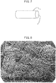
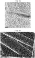
- the present invention provides a carbon fiber having a novel structure in which very thin graphenes are fixed three-dimensionally in a space and a method for producing the same.
- the inventors of the present invention have made intensive study and as a result, have found that the above problems can be solved by pre-baking a fiber an organic compound so as to contain remaining hydrogen and then subjecting the pre-baked fiber to hot isostatic pressing treatment (HIP treatment) under predetermined conditions, and have conducted further studies to complete the present invention.
- HIP treatment hot isostatic pressing treatment
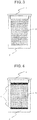
- the present invention relates to a method for producing a carbon fiber having an outermost surface composed of edges of graphenes, as specified in present claims.
- the production method comprises steps of pre-baking a fiber of an organic compound so as to contain remaining hydrogen, putting the pre-baked fiber of an organic compound in a closed vessel made of a heat resistant material and subjecting the pre-baked fiber together with the vessel to hot isostatic pressing treatment using a compressed gas atmosphere, wherein a maximum ultimate temperature in the hot isostatic pressing treatment is 1000 to 2000°C.
- the remaining hydrogen is preferably 500 ppm or more.
- a pre-baking temperature is preferably 1000°C or lower.
- the fiber of an organic compound is in the form of yarn, woven fabric, non-woven fabric, blended yarn with other fiber, or woven fabric or non-woven fabric made of the blended yarn.
- a mean diameter of the fiber of an organic compound before the pre-baking is preferably 500 ⁇ m or less.
- the closed vessel made of a heat resistant material is preferably a graphite closed vessel.
- the graphite closed vessel preferably has an open pore ratio of less than 20% and is of triangular screw type.
- the organic compound is preferably one or more selected from the group consisting of starch, cellulose, protein, collagen, alginic acid, dammar, rosin, gutta-percha, natural rubber, cellulose resin, cellulose acetate, cellulose nitrate, cellulose acetate butyrate, casein plastic, soybean protein plastic, phenol resin, urea resin, melamine resin, benzoguanamine resin, epoxy resin, diallyl phthalate resin, unsaturated polyester resin, a bisphenol A type epoxy resin, Novolac type epoxy resin, polyfunctional epoxy resin, alicyclic epoxy resin, alkyd resin, urethane resin, polyester resin, vinyl chloride resin, polyethylene, polypropylene, polystyrene, polyisoprene, butadiene, nylon, vinylon, acrylic fiber, rayon, polyvinyl acetate, ABS resin, AS resin, acrylic resin, polyacetal, polyimide, polycarbonate, modified polyphenylene ether, polyarylate, polysulfate, cellulose
- the hot isostatic pressing treatment is preferably carried out in such a state that a part or the whole around the pre-baked fiber of an organic compound charged in the closed vessel made of graphite is covered with a spacer and a sleeve.
- the spacer and the sleeve is preferably made of one or more selected from the group consisting of glassy carbon, diamond-like carbon, and amorphous carbon.
- the present invention further relates to a carbon fiber having an outermost surface composed of edges of graphenes in the form of yarn, woven fabric, or non-woven fabric.
- the present invention further relates to a method for producing a graphene dispersion comprising graphenes and a solvent, comprising:
- an aspect ratio of the carbon fiber is preferably 2.5 or more.
- a mean diameter of the carbon fiber is preferably within a range from 0.1 to 500 ⁇ m.
- the solvent preferably further comprises a dispersant.
- a carbon fiber having an outermost surface composed of edges of graphenes can be produced by HIP treatment being a simple treatment method using chemical vapor deposition (CVD) reaction, and such a carbon fiber can be produced easily at low-cost, as well as in a short period of time and in large amounts.
- HIP treatment being a simple treatment method using chemical vapor deposition (CVD) reaction
- the thus obtained carbon fiber of the present invention has edges of graphenes at the outermost surface, which means broad surface areas of graphenes formed by three dimensional network structure of graphenes exist inside the fiber. Therefore, the carbon fiber of the present invention enables the edges and surface areas of the graphenes to be contacted with various gases and liquids efficiently.
- the carbon fiber of the present invention can be suitably used for transparent conductive materials for forming transparent flexible conductive films; high heat-release and heat-transfer materials for forming heat-release sheets for, for example, smartphone; conductive inks for printable electronics; conductive materials and semiconductor materials for forming semiconductor inks; conductive additive materials for adding to electrodes for lithium-ion batteries, lithium-ion capacitors, fuel cell batteries, other primary and secondary batteries, and the like; gas diffusion layers of fuel cell batteries; catalyst materials used for, for example, reduction of active oxygen; electrodes for, for example, Field Emission Displays and X-ray tubes; needles of tunneling microscopes, and the like.
- a woven fabric or non-woven fabric comprising carbon fibers having an outermost surface structure composed of edges of graphenes.
- a woven fabric or non-woven fabric comprising carbon fibers having an outermost surface structure composed of edges of graphenes.
- it can, if necessary, be put into a large-sized, a sheet-like, or a curved form or into a variety of forms for, for example, lining an inner surface of a vessel, covering a cylindrical part, using it as mat consisting of multilayered lamination, or using it in a roll shape by rolling, it can be fixed to and filled at various sites.
- graphenes which are expected to be put into practical use for various applications, can be provided as an ideal material suitable for multiple applications.
- carbon fibers of the present invention by blending fibers of an organic compound being starting material with other fibers (for example, carbon fiber) to obtain blended yarns and making the blended yarns into a woven fabric or non-woven fabric beforehand, a woven fabric or non-woven fabric being a composite material with other yarns can be produced.
- other fibers for example, carbon fiber
- a graphene dispersion in which graphenes are dispersed in a solvent can be obtained easily by using the carbon fiber of the present invention.
- the method for producing a carbon fiber having an outermost surface composed of edges of graphenes of the present invention that is, steps of pre-baking a fiber of an organic compound so as to contain a predetermined amount of remaining hydrogen, putting the pre-baked fiber of an organic compound in a closed vessel made of a heat resistant material and subjecting the pre-baked fiber together with the vessel to hot isostatic pressing treatment using a compressed gas atmosphere will be described below.
- Examples of usable organic compound are those mentioned below.
- natural organic polymers such as starch, cellulose, protein, collagen, alginic acid, dammar, rosin, gutta-percha, and natural rubber
- semisynthetic polymers such as cellulose resin, cellulose acetate, cellulose nitrate, cellulose acetate butyrate, casein plastic, and soybean protein plastic
- synthetic polymers such as thermosetting reins such as phenol resin, urea resin, melamine resin, benzoguanamine resin, epoxy resin, diallyl phthalate resin, unsaturated polyester resin, bisphenol A type epoxy resin, Novolac type epoxy resin, polyfunctional epoxy resin, alicyclic epoxy resin, alkyd resin, and urethane resin
- thermoplastic resins such as polyester resins (polyethylene terephthalate (PET) resin, polytrimethylene terephthalate resin, polybutylene terephthalate resin, polyethylene naphthalate resin, polybutylene naphthalate
- the above organic compounds can be used alone or in combination of two or more thereof.
- an organic compound used in the present invention is one in the form of fiber.
- fiber refers to one in the form of long and fine yarn.
- the length of the fiber is not particularly limited, and for example, may be about 1 ⁇ m, or about 1 km.
- the mean fiber diameter is preferably 0.1 ⁇ m or more, more preferably 1 ⁇ m or more. If the mean fiber diameter is less than 0.1 ⁇ m, the strength for maintaining the form of fiber is insufficient and the fiber tends to be pulverized to fine powder easily.
- the mean fiber diameter is preferably 500 ⁇ m or less, more preferably 200 ⁇ m or less, further preferably 100 ⁇ m or less. If the mean fiber diameter is over 500 ⁇ m, the fiber tends to have an increased stiffness and lack flexibility as a fiber.
- the aspect ratio is 2.5 or more, more preferably 3.0 or more.
- the reason why the organic compound used as a starting material has such an aspect ratio is such that as explained infra, when a graphene dispersion is prepared from the carbon fiber of the present invention, a high-purity graphene dispersion tends to be obtained easily only by soaking the carbon fiber of the present invention in a solvent, carrying out ultrasonic wave treatment and filteration, without pulverization of the carbon fiber or centrifugation for separating the graphene dispersion.
- the upper limit of the aspect ratio is not particularly limited, and, for example, can be about 10000000.
- the fiber of the organic compound used in the present invention is in the form of yarn (for example, long fiber, short fiber, twisted yarn, hollow yarn), and the yarn can also be converted to various forms, specifically, for example, woven fabrics (for example, plain-woven fabric, satin fabric, twill fabric) or non-woven fabrics.
- the fiber of the organic compound used in the present invention may be in the form of blended yarn with other fiber (for example, carbon fiber), and the blended yarn may also be converted towoven fabric (for example, plain-woven fabric, satin fabric, twill fabric) or non-woven fabric.
- pre-baking is a step of heating and baking fibers of an organic compound being a starting material and adjusting the amount of remaining hydrogen contained therein within a predetermined range.
- the pre-baking is carried out at a specified pre-baking temperature in an inert atmosphere, such as mainly in a nitrogen gas stream.
- an electric heating or gas heating type externally heating batch oven, continuous multi-tubular oven, internal heating rotary kiln, rocking kiln, or the like is used.
- a pre-baking temperature is about 1000°C or lower, preferably about 950°C or lower, more preferably about 850°C or lower, further preferably about 800°C or lower, particularly preferably about 700°C or lower. If the pre-baking temperature is over about 1000°C, gases such as hydrogen, hydrocarbon, carbon monoxide, and water required for CVD reaction tend not to be generated sufficiently in the HIP treatment. Meanwhile, the lower limit of the pre-baking temperature is about 300°C, preferably about 400°C.
- the lower limit is less than about 300°C, oxygen, nitrogen, and hydrogen atoms contained in an organic compound do not become thermodynamically unstable and are not released enough to a certain extent, whereby a certain degree of polymerization and carbonization of the organic compound which is necessary as a pre-baked starting material tends not to proceed.
- the amount of the remaining hydrogen is a value correlating with the pre-baking temperature, that is, as the pre-baking temperature increases, the amount of the remaining hydrogen tends to decrease. From the viewpoint of production of the target product of the present invention, it is necessary that the amount of the remaining hydrogen is enough to generate sufficient amounts of gases such as hydrogen, hydrocarbon, carbon monoxide, and water necessary for the CVD reaction at the time of HIP treatment.
- the amount of hydrogen is usually about 500 ppm or more, preferably about 1000 ppm or more, more preferably about 5000 ppm or more, further preferably about 6500 ppm or more, particularly preferably about 10000 ppm or more, still more particularly preferably about 20000 ppm or more.
- the closed vessel (for example, graphite crucible) made of a heat-resistant material relating to the present invention functions as a reaction vessel for causing the CVD reaction with gases such as hydrogen, hydrocarbon, carbon monoxide, and water generated from the pre-baked starting material during the HIP treatment. It is necessary to properly select material of the vessel and closing structure thereof for causing a chemical reaction without scattering the generated reaction gas outside the vessel while keeping isotropic high pressure by a gas pressure. If the material is too dense, a difference in pressure between the inside and the outside of the vessel (for example, crucible) arises, which results in an explosive breakdown of the vessel. On the other hand, if the material is too porous, the reaction gas generated inside the vessel is easily scattered outside the vessel and efficiency of the chemical reaction is lowered.
- gases such as hydrogen, hydrocarbon, carbon monoxide, and water generated from the pre-baked starting material during the HIP treatment.
- the material and structure of the vessel are also properly selected in consideration of necessity of taking a HIP-treated product out of the vessel and closing the vessel (for example, crucible) as easily as possible in view of facilitating charging of the starting material before the HIP treatment, exposure to high temperature of about 1000°C or more during the HIP treatment, and necessity of maintaining strength of the vessel at high temperature so as to be capable of withstanding the inside pressure caused by generation of the reaction gas from the pre-baked starting material.
- Examples of the heat resistant materials constituting the reaction vessel are graphite and in addition, ceramics such as alumina, magnesia, and zirconia, and metals such as iron, nickel, zirconium, and platinum.
- Graphite material is suitable as a material for the vessel (for example, crucible).
- the graphite vessel can specifically be made of artificial graphite materials prepared by extrusion molding, CIP molding, squeeze molding, vibration molding, or rammer molding, hard carbon materials including glassy carbon prepared mainly by thermosetting resin molding, carbon fiber-reinforced carbon materials, or composite materials thereof.
- the porosity of the graphite material is important for efficiently causing the chemical reaction in the vessel (for example, crucible), and therefore, a material having an open pore ratio of less than 20% can be used suitably.
- the reaction gases are diffused outside the vessel (for example, crucible), and therefore, a concentration of the gases necessary for generating the graphite cannot be kept.
- a screw-capped graphite crucible can be used so that charging of the pre-baked starting material in the vessel and discharging of the product after the HIP treatment can be carried out efficiently.
- the inner wall 2a at the top of the crucible body 2 and the outer periphery 1a of the crucible cap 1 have thread-cutting by specified tap processing, and thereby the crucible can be closed by turning the cap 1 to the thread after charging of the pre-baked starting material 3.
- the pre-baked starting material 3 or by covering the whole (or a part) around the pre-baked starting material 3 with spacers 4 and a sleeve 5 ( Fig. 6 ).
- the carbon material for the spacer and the sleeve are glassy carbon, diamond-like carbon, amorphous carbon and the like, and one of them can be used alone, or two or more thereof can be used together.
- the open pore ratio of the carbon material is usually less than 0.5%. Even if the pre-baked starting material is covered with spacers and a sleeve having an open pore ratio of 0%, there is a gap between the spacers and the sleeve. Therefore, the pre-baked starting material cannot be closed completely with the spacers and the sleeve.
- Examples of the screw of the screw-capped graphite crucible are a triangular screw (having a cross-section of screw thread in the form like equilateral triangle), a square screw, a trapezoid screw, and the like, and among these, a triangular screw is preferred.
- the thus obtained pre-baked starting material (fiber of an organic compound) containing remaining hydrogen is subjected to HIP treatment under predetermined conditions.
- the maximum ultimate temperature at the HIP treatment is from about 1000°C to about 2000°C, preferably from about 1200°C to about 1900°C, more preferably from about 1400°C to about 1800°C. If the maximum ultimate temperature is less than about 1000°C, there is a tendency that thermal excitation of gases generated from the pre-baked starting material is difficult to occur and CVD reaction is difficult to proceed. On the other hand, if the maximum ultimate temperature is over about 2000°C, the target product tends to be damaged by etching with the exciting hydrogen.
- the maximum ultimate temperature at the HIP treatment is higher than the pre-baking temperature, and is preferably higher by 400°C or more.
- the temperature elevating rate at the HIP treatment is from about 100°C/h to about 1000°C/h, preferably from about 300°C/h to about 800°C/h. If the temperature elevating rate is less than about 100°C/h, the reaction gases such as hydrogen generated from the pre-baked starting material are diffused into treatment media such as argon gas, and CVD reaction tends not to occur sufficiently. Meanwhile, if the temperature elevating rate is over about 1000°C/h, the heater capacity of treatment equipment needs to be increased considerably, and thus, the equipment cost tends to increase significantly.
- the maximum ultimate pressure at the HIP treatment varies with a mean fiber diameter of the pre-baked starting material, and is usually within the range from about 1 MPa to about 300 MPa, preferably from about 10 MPa to about 200 MPa, more preferably from about 30 MPa to about 200 MPa. For example, in the case of a large mean fiber diameter, a higher pressure is required as the maximum ultimate pressure, and in the case of a small mean fiber diameter, a lower pressure suffices.
- the mean fiber diameter is about 10 ⁇ m or more
- the maximum ultimate pressure is preferably 40 MPa or more, and when the mean fiber diameter is about 5 ⁇ m or less, the HIP treatment can be suitably carried out at the maximum ultimate pressure of about 20 MPa.
- the pressure is first elevated to a specified pressure before the temperature reaches the approximate pre-baking temperature (pressure-preceding pattern), so that the reaction gases generated from the pre-baked starting material are not diffused too much, and then, the temperature is elevated to the approximate pre-baking temperature, and thereafter, the temperature and pressure are elevated to the maximum ultimate temperature and the maximum ultimate pressure, as needed.
- Example of the above specified pressure is about 40 MPa.
- the pressure-preceding pattern as mentioned above is not necessary particularly, and HIP treatment can be carried out efficiently.
- a carbon fiber having an outermost surface composed of edges of graphenes according to the present invention can be obtained.
- Form of the carbon fiber to be obtained varies depending on form of a fiber of an organic compound used as the starting material. Size of the carbon fiber is shrunk slightly through the HIP treatment.
- a carbon fiber in the form of yarn can be obtained, and with the use of a fiber of an organic compound in the form of woven fabric or non-woven fabric, a carbon fiber in the form of woven fabric or non-woven fabric can be obtained.
- a fiber of an organic compound is in the form of blended yarn with other fiber (for example, carbon fiber)
- the corresponding carbon fiber in the form of yarn, woven fabric, or non-woven fabric, respectively that is, the carbon fiber of the present invention as a composite material with other fiber in the form of yarn, woven fabric or non-woven fabric
- the outermost surface of the carbon fiber refers to a surface being in parallel with the fiber axis of the carbon fiber and recognized as the outermost part of the fiber ( Fig. 7 ).
- a graphene dispersion can be prepared easily with a carbon fiber of the present invention. Namely, with the carbon fiber of the present invention, particularly a carbon fiber having an aspect ratio of a predetermined value or more according to the present invention, a high-purity graphene dispersion can be obtained easily only by soaking the carbon fiber of the present invention into a solvent, carrying out ultrasonic wave treatment, and filtration, without pulverization of the carbon fiber or centrifugation for separating the graphene dispersion.
- the graphene dispersion refers to one wherein many graphene fragments are dispersed in a solvent.
- the aspect ratio thereof is preferably 2.5 or more, more preferably 3.0 or more. If the aspect ratio is less than 2.5, the purity of the graphene dispersion obtained by filtration tends to be lowered. Meanwhile, the upper limit of the aspect ratio is not particularly limited, and, for example, may be about 10000000.
- the pressurized medium gas may be removed by subjecting the carbon fiber to heat treatment in advance (for example, at a temperature of 100°C or more) or the crystallinity of the graphene may be increased, if necessary, and then, the subsequent steps may follow.
- the carbon fiber of the present invention may be soaked into a solvent by a conventional method, for example, by putting the carbon fiber into a solvent and allowing the solvent to stand. At this time, the solvent may be stirred to such an extent not to pulverize the carbon fiber.
- solvent examples include 1,2-dichloroethane, benzene, thionyl chloride, acetyl chloride, tetrachloroethylene carbonate, dichloroethylene carbonate, benzoyl fluoride, benzoyl chloride, nitromethane, nitrobenzene, acetic anhydride, phosphorus oxychloride, benzonitrile, selenium oxychloride, acetonitrile, tetramethylsulfone, dioxane, 1,2-propanediol carbonate, benzyl cyanide, ethylene sulfite, isobutyronitrile, propionitrile, a carbonic acid ester such as dimethyl carbonate, propylene carbonate, ethyl methyl carbonate, diethyl carbonate, and ethylene carbonate; phenyl phosphoric acid difluoride, methyl acetate, n-butyronitrile, acetone, ethyl
- a dispersant can be added to these solvents in order to increase an amount of graphenes to be dispersed or to prevent agglomeration of the graphenes in a solvent.
- a dispersant are surfactants and, in addition, those having a weak binding force to graphene and an electric attracting force such as a Coulomb's force and having a hydrophilic functional group such as hydroxyl and carboxyl in a structure thereof.
- Examples of the latter dispersants are monomers such as phenols such as phenol and a naphthol having hydroxyl bonded to benzene nucleus and polymers thereof, monomers such as styrene, propylene, acrylonitrile and vinyl acetate having carbon double bond and polymers thereof, proteins such as collagen, keratin, actin, myosin, casein, albumin, GFP and RFP, amino acids such as glycine, tyrosine, threonine and glutamine, and the like.
- monomers such as phenols such as phenol and a naphthol having hydroxyl bonded to benzene nucleus and polymers thereof, monomers such as styrene, propylene, acrylonitrile and vinyl acetate having carbon double bond and polymers thereof, proteins such as collagen, keratin, actin, myosin, casein, albumin, GFP and RFP, amino acids such as glycine, tyrosine
- suitably usable surfactants are: anion based surfactants (anionic surfactants) such as fatty acid salts (for example, sodium dodecanoate), cholic acid salts (for example, sodium cholate), monoalkyl sulfates (for example, sodium lauryl sulfate), alkyl polyoxyethylene sulfate, alkyl benzene sulfonates (for example, sodium dodecyl benzene sulfonate), and monoalkyl phosphate; cation based surfactants (cationic surfactants) such as alkyl trimethyl ammonium salts (for example, cetyl trimethyl ammonium bromide), dialkyl dimethyl ammonium salts (for example, didecyl dimethyl ammonium chloride), and alkyl benzyl dimethyl ammonium salts (for example, alkyl benzyl dimethyl ammonium chloride); amphoteric surfactants (Gemini surfactants)
- dimethylformamide water to which a dispersant (preferably a surfactant) is added, 2-methoxyethanol, 2-propanol, and the like.
- An amount of a dispersant is within a range from 0.001 to 10% by weight, preferably from 0.02 to 5% by weight based on the weight of a solvent, but it is not always limited to these ranges if a film such as a transparent conductive film or a conductive film that is formed is to be washed up.
- An amount of carbon fibers of the present invention is within a range from 0.001 to 50% by weight, preferably from 0.01 to 10% by weight based on the weight of a solvent.
- a means for applying an ultrasonic wave is not particularly limited, and application of an ultrasonic wave can be carried out by using, for example, an ultrasonic cleaner.
- a frequency of an ultrasonic wave to be applied is within a range from 20 to 120 kHz, preferably from 20 to 40 kHz.
- Time required for applying an ultrasonic wave is from about 1 to about 1200 minutes, preferably from about 20 to about 600 minutes.
- a means for filtration is also not particularly limited, and the filtration can be carried out by using, for example, a stainless-steel mesh.
- the sieve openings of the mesh may be suitably selected according to the size of carbon fibers to be filtered. For example, if a stainless-steel mesh is used, the sieve openings is preferably 1 to 3000 ⁇ m, more preferably 5 to 100 ⁇ m.
- the thus obtained graphene dispersion can be used, for example, as an ink to be used for forming a circuit and a thin film for printable electronic products.
- a circuit and the like can be formed by printing the dispersion on a surface of a substrate by various printing methods such as flexographic printing (letterpress printing), offset printing (planographic printing), gravure printing (intaglio printing), screen printing, ink jet printing, electrophotography, heat transfer, and laser transfer.
- a desired circuit can be obtained by applying the dispersion on a substrate by wet coating such as spin coating, slit coating, bar coating, blade coating or spray coating and then carrying out patterning on the coated substrate by using a patterning technique such as nano-micro contact printing, dip-pen lithography, nano-micro transfer, nanoimprinting, electron beam lithography, or photolithography.
- wet coating such as spin coating, slit coating, bar coating, blade coating or spray coating
- a patterning technique such as nano-micro contact printing, dip-pen lithography, nano-micro transfer, nanoimprinting, electron beam lithography, or photolithography.
- various high functional films such as a transparent conductive film, a highly conductive film, and a high thermal conduction film containing the graphenes can be obtained by dispersing or mixing the graphene dispersion obtained above in a starting resin such as a PET film, an ionomer film (IO film), a polyethylene film made of high density polyethylene (HDPE), medium-density polyethylene (MDPE), low-density polyethylene (LDPE), linear low-density polyethylene (L-LDPE), or metallocene catalyst type linear low-density polyethylene (mL-LDPE), hard, semi-hard or soft polyvinyl chloride film (PVC film), polyvinylidene chloride film (PVDC film), polyvinyl alcohol film (PVA film), polypropylene film (PP film), polyester film, polycarbonate film (PC film), polystyrene film (PS film), polyacrylonitrile film (PAN film), ethylene-vinyl alcohol copolymer film (EVOH film
- resin composite materials such as molded resin articles and fiber-reinforced plastics (FRP) containing the graphenes and having improved electric conductivity, thermal conductivity, heat resistance, strength, fracture toughness and flexibility
- FRP fiber-reinforced plastics
- natural resins derived from plants such as rosin, dammar, mastic, copal, amber, balsam and natural rubber
- natural resins derived from animals such as shellac, glue, tortoiseshell and casein
- thermosetting resins such as phenol resin, epoxy resin, melamine resin, urea resin, unsaturated polyester resin, alkyd resin, polyurethane and thermosetting polyimide
- thermoplastic resins such as polyethylene, high density polyethylene, medium-density polyethylene, low-density polyethylene, polypropylene, polyvinyl chloride, polyvinylidene chloride, polystyrene, polyvinyl acetate, polytetrafluoroethylene, ABS resin, AS resin
- rubbers and rubber composite materials containing the graphenes and having improved electric conductivity, thermal conductivity, heat resistance, strength, and flexibility can be obtained by dispersing or mixing the obtained graphene dispersion in or with synthetic rubbers such as acrylic rubber, nitrile rubber, isoprene rubber, urethane rubber, ethylene propylene rubber, epichlorohydrine rubber, chloroprene rubber, silicone rubber, styrene-butadiene rubber, butadiene rubber, fluorine-containing rubber, and polyisobutylene rubber, and then, kneading, drying, and molding.
- synthetic rubbers such as acrylic rubber, nitrile rubber, isoprene rubber, urethane rubber, ethylene propylene rubber, epichlorohydrine rubber, chloroprene rubber, silicone rubber, styrene-butadiene rubber, butadiene rubber, fluorine-containing rubber, and polyisobutylene rubber
- various composite materials containing the graphenes and having improved electric conductivity, thermal conductivity, heat resistance, strength, fracture toughness, and electromagnetic wave shielding property can be obtained by dispersing or mixing the obtained graphene dispersion in or with ceramic materials such as oxides such as pottery, glass, cement, mortar, gypsum, enamel, alumina and zirconia, hydroxides such as hydroxyapatite, carbides such as silicon carbide and boron carbide, carbonates, nitrides such as silicon nitride, boron nitride, aluminum nitride and GaN, halides such as fluophosphate, phosphate, barium titanate, high temperature superconductive ceramics, ferrite, lead zirconium titanate, steatite, zinc oxide, and GaAs, and then, kneading, drying, molding, baking, and sintering.
- ceramic materials such as oxides such as pottery, glass, cement, mortar, gypsum, enamel, a
- various materials containing the graphenes and having improved electric conductivity, thermal conductivity, heat resistance, magnetic properties, strength, elasticity, and fracture toughness can be obtained by dispersing or mixing the obtained graphene dispersion in or with elements such as tungsten, rhenium, osmium, tantalum, molybdenum, niobium, iridium, ruthenium, hafnium, technetium, boron, rhodium, vanadium, chromium, zirconium, platinum, thorium, lutecium, titanium, palladium, protactinium, thulium, scandium, iron, steel, cast iron, yttrium, erbium, cobalt, holmium, nickel, dysprosium, silicon, terbium, curium, gadolinium, beryllium, manganese, americium, promethium, uranium, copper, samarium, gold, actinium,
- a graphene refers to a single-layer or multi-layer (up to several-layer, for example, about 10-layer) graphene.
- edges refer to edges of carbon hexagonal planes forming the graphene. If thickness of a graphene is very thin, the edge may be rolled by Van der Waals force of itself, and edges of the graphenes of the present invention also include the edges in such a state.
- an amount of hydrogen is measured in accordance with General Rules for Determination of Hydrogen in Metallic Materials (JIS Z 2614: 1990. Determination is carried out by an inert gas heating method which is a condition for "steel". The measurement is concretely conducted by heating a sample up to 2000°C under argon gas atmosphere and measuring an integrated amount of generated hydrogen by gas chromatograph.).
- the open pore ratio is a ratio of a volume of a (open) cavity into which a liquid or gas can invade to a volume obtained from an outer shape of a material .
- a material having a high open pore ratio has continuous pores and has air permeability.
- the open pore ratio is obtained from the following equation.
- Open pore ration % Apparent specific gravity ⁇ Bulk specific gravity / Apparent specific gravity ⁇ 100
- Apparent specific gravity A value measured using a sample before pulverization by a helium gas substitution pycnometer method with a densimeter AccuPyc 1330-PCW available from Shimadzu Corporation.
- Bulk specific gravity A value obtained by dividing a sample weight by a volume calculated from outer dimensions of the sample.
- the total pore ratio is a ratio of a volume of a total cavity (including closed pores in addition to open pores) to a volume calculated from an outer shape of a sample.
- the total pore ratio is obtained from the following equation.
- Total pore ration % True specific gravity ⁇ Bulk specific gravity / True specific gravity ⁇ 100
- the true specific gravity is a specific gravity measured using a target material in a state of being pulverized into a fine powder in order to minimize an effect attributable to a cavity contained in the target material, and in this specification, the true specific gravity is measured using a powder sample having passed through a 74 ⁇ m filter.
- An apparent specific gravity, a bulk specific gravity, and a true specific gravity are synonymous with an apparent density, a bulk density, and a true density, respectively.
- a spacer and a sleeve are used being placed inside a closed vessel made of graphite and are inserted between inner wall of the vessel and a pre-baked starting material so that the both do not come into direct contact with each other.
- the spacer is one covering a pre-baked starting material mainly from the top and bottom thereof, and the sleeve is one covering a pre-baked starting material from the side thereof.
- distinction between the spacer and the sleeve is meaningless depending on a shape of vessel.
- a mean fiber diameter is a value measured with scanning electron microscope (SEM), and is a mean value of randomly selected 30 fibers.
- a mean fiber length is a value measured in the same manner.
- a numerical range shown, for example, by from 1200 to 1900 means a range of 1200 or more and 1900 or less unless it is inconsistent with the rest of the specification.
- Yarns of phenol resin having a mean fiber diameter of 20 ⁇ m were woven in plain weave, and a fabric having a weight per unit area of 200 g/m 2 and a thickness of 600 ⁇ m was made and cut into 50 mm wide and 300 mm long. After that, each of the fabrics was pre-baked at the maximum ultimate temperatures of 500°C, 600°C, 700°C, 900°C, 1000°C, or 1200°C under an inert gas atmosphere. Amounts of hydrogen remaining in the starting materials after the pre-baking were analyzed in accordance with General Rules for Determination of Hydrogen in Metallic Materials (JIS Z 2614: 1990). The results are shown in Table 1.
- the pre-baked starting material fabric which was pre-baked at each temperature was charged in a screw-capped (triangular screw) graphite crucible made of a graphite having a bulk density of 1.80 and an open pore ratio of 10%, and a threaded top cover was turned to be closed, and thus the crucible containing the pre-baked starting material was closed.
- a temperature and pressure inside the equipment were increased to 600°C and 70 MPa, respectively in one hour using argon gas, and thereafter, heating at a temperature elevating rate of 500°C per hour and pressurizing were continued to reach a maximum ultimate pressure of 190 MPa and a maximum ultimate temperature of 1500°C.
- the surfaces of the resultant carbon fibers were observed with a scanning electron microscope (SEM) and a transmission electron microscope to examine appearances of generated graphenes.
- SEM scanning electron microscope
- Table 1 As shown in Table 1, in the case where the pre-baking temperature was 500°C and the remaining hydrogen was 18500 ppm, generation of graphene was most remarkable. As the pre-baking temperature increased, generation of graphene was smaller. In the case where the pre-baking temperature was 1200°C and the remaining hydrogen was 220 ppm, graphene was hardly generated.
- Fig. 8 is a photograph by SEM showing a surface of Sample No. 1-(1). It is seen that the sample was converted to a woven fabric of carbon fiber while maintaining the form of a woven fabric of phenol resin fiber.
- Fig. 9 is an enlarged SEM photograph of fibers in the woven fabric of Fig. 8 .
- Fig. 10 is an further enlarged SEM photograph of the surface of the fibers. It is observed that graphenes grow thick uniformly on the surface of the carbon fiber constituting the woven fabric, and the outermost surface of the carbon fiber is composed of edges of graphenes.
- Fig. 11 is an enlarged SEM photograph of graphenes in Fig. 10 showing that each graphene is grown radially from the surface of the fiber independently without contacting with one another.
- Fig. 12 is an enlarged photograph of Fig. 11 using a high-resolution electron micrograph.
- Fig. 13 is a photograph with a high-resolution electron micrograph wherein graphenes shown in Fig.
- Fig. 12 are further enlarged at 300,000-fold magnification.
- Fig. 12 shows thin tips of a graphene rolled as a cigar and looking like a needle, whereby it is seen that the graphene has a large Van der Waals force.
- Fig. 13 electron beams of an accelerating voltage of 2 kv penetrate through the graphene, whereby it is seen that the graphene is very thin.
- TEM transmission electron microscope
- the sample was soaked in an isopropyl alcohol and subjected to ultrasonic wave treatment at the frequency of 24 kHz for 20 minutes to detach the graphenes from the carbon fibers.
- the resultant graphene dispersion was dropped into a microgrid for TEM observation to prepare a sample for observation.
- Fig. 14 is a TEM photograph of graphenes at a low magnification showing thin graphenes and the tips being rolled like a cigar, which look like a thick needle.
- Fig. 15 is a TEM photograph wherein the cigar-like tip of the graphene is enlarged. The lattice image of the tip of the graphene in Fig.
- each of the fabrics was pre-baked at the maximum ultimate temperature of 600°C under an inert gas atmosphere.
- the pre-baked starting material fabrics were subjected to HIP treatment in the same manner as in Example 1 except that the maximum ultimate temperature was changed to 1200°C or 1300°C and the maximum ultimate pressure was changed to 90 MPa in the HIP treatment to obtain target products of Sample Nos. 2-(1) and 2-(2).
- Pre-baking Hot isostatic pressing treatment Appearance of generated graphene Pre- baking temp. (°C) Amount of remaining hydrogen (ppm) Maximum ultimate temp. (°C) Maximum ultimate pressure (MPa) 2-(1) 600 10100 1200 190 Minute graphenes were generated. 2-(2) 600 10100 1300 190 Minute graphenes were generated remarkably.
- Example 2 After a woven fabric prepared in the same manner as in Example 1 was cut into 50 mm wide and 300 mm long, each of the fabrics was pre-baked at the maximum ultimate temperature of 600°C under an inert gas atmosphere. The pre-baked starting material fabrics were subjected to HIP treatment in the same manner as in Example 1 except that the maximum ultimate temperature was changed to 1400°C to obtain a target product of Sample No. 3-(1).
- Example 3 The same treatment as in Example 3 was carried out by using various resin fibers shown in Table 4 (that is, long fiber, short fiber, twisted yarn, plain-woven fabric, satin fabric, twill fabric, non-woven fabric, as well as plain-woven fabric made of blended yarn of one of the resin fibers and a carbon fiber).
- Table 4 that is, long fiber, short fiber, twisted yarn, plain-woven fabric, satin fabric, twill fabric, non-woven fabric, as well as plain-woven fabric made of blended yarn of one of the resin fibers and a carbon fiber.
- the carbon fibers of the present invention having an outermost surface composed of edges of graphenes were generated, while maintaining the form of phenol resin being a starting material.
- TABLE 4 Sample No. Starting material Mean fiber diameter ( ⁇ m Mean fiber length (mm) Appearance of generated graphene Organic compound Form 4-(1) Phenol resin Long fiber 18 100 Generated. 4-(2) Phenol resin Long fiber 30 200 Generated. 4-(3) Phenol resin Short fiber 18 0.2 Generated. 4-(4) Phenol resin Short fiber 25 0.5 Generated. 4-(5) Phenol resin Short fiber 35 0.4 Generated. 4-(6) Phenol resin Twisted yarn (Number of twists: 100) 14 1000 Generated.
- Phenol resin Plain-woven fabric (Width: 100 mm, Length: 300 mm) (Weight per unit area: 220 g/m 2 ) 35 Generated.
- 4-(8) Phenol resin Satin fabric (Width: 100 mm, Length: 300 mm) (Weight per unit area: 290 g/m 2 14 Generated.
- 4-(9) Phenol resin Twill fabric (Width: 100 mm, Length: 300 mm) (Weight per unit area: 300 g/m 2 ) 14 Generated.
- 4-(10) Phenol resin Non-woven fabric (Width: 100 mm, Length: 200 mm) (Weight per unit area: 120 g/m 2 ) 20 Generated.
- “Infusibilization” in the starting material of Sample No. 4-(11) refers to a process in which a polyacrylonitrile resin is heated at a temperature of 200 to 300°C in the atmosphere beforehand to introduce oxygen groups and the like into the chemical structure of the polyacrylonitrile resin so that the resin may not be melted at the step of pre-baking.
- the carbon fibers of the present invention obtained from Sample No. 4-(7) in Example 4 were subjected to the same treatment as described above except that a stainless-steel mesh with sieve openings of 102 ⁇ m was used, and a graphene dispersion (2) was obtained as a filtrate. It took about 3 minutes to filter by using the stainless-steel mesh.
- Fig. 22 is an FE-SEM photograph showing carbon fibers remaining on the stainless-steel mesh with sieve openings of 25 ⁇ m in the preparation step of the graphene dispersion (1). The figure shows that the carbon fibers from which graphenes were separated remain on the mesh by effective filtration.
- Fig. 23 is an FE-SEM photograph showing graphene residues after the evaporation of the solvent in the graphene dispersion (1).
- Fig. 24 is an enlarged view of the above figure. Whereas the carbon fibers from which graphenes were separated or by-products such as amorphous carbon were not observed, only graphenes after evaporation to dryness were observed. Thus, it was confirmed the purity of the graphenes was good.
- carbon fibers (Sample Nos. 6-(1) to 6-(3)) were produced in the same manner as in Sample No. 4-(3) in Example 4 except that the lengths of the short fibers of the phenol resin being a starting material were changed so that the aspect ratio is 5.6, 2.8, and 1.7, respectively.
- Graphene dispersions (3) to (5) were prepared in the same manner as in Example 5 by using the obtained carbon fibers.
- the amount of dispersed graphenes is 0.005 mg/ml, which is very small. Therefore, it is desirable that the aspect ratio of an organic compound used as a starting material is about 2.5 or more.
- Carbon fibers obtained by the production method of the present invention can be suitably used for transparent conductive materials for forming transparent flexible conductive films; high heat-release and heat-transfer materials for forming heat-release sheets for, for example, smartphone; conductive inks for printable electronics; conductive materials and semiconductor materials for forming semiconductor inks; conductive additive materials for adding to electrodes for lithium-ion batteries, lithium-ion capacitors, fuel cell batteries, other primary and secondary batteries, and the like; gas diffusion layers of fuel cell batteries; catalyst materials used for, for example, reduction of active oxygen; electrodes for, for example, field emission displays and X-ray tubes; needles of tunneling microscopes, and the like.
Description
- The present invention relates to a carbon fiber suitably usable for transparent conductive materials for forming transparent flexible conductive films; high heat-release and heat-transfer materials for forming heat-release sheets for, for example, smartphone; conductive inks for printable electronics; conductive materials and semiconductor materials for forming semiconductor inks; conductive additive materials for adding to electrodes for lithium-ion batteries, lithium-ion capacitors, fuel cell batteries, other primary and secondary batteries, and the like; gas diffusion layers of fuel cell batteries; catalyst materials used for, for example, reduction of active oxygen; electrodes for, for example, field emission displays (FED) and X-ray tubes; needles of tunneling microscopes, and the like, and more particularly, to a carbon fiber comprising graphenes, and to a method for producing the same.
- Conventional methods for producing carbon materials comprising graphenes include various methods such as tape removal method (
non-patent documents 1 and 2), solvent extraction method (non-patent document 3), substrate method (non-patent documents 4 and 5), and sublimation method (non-patent documents - Thin sheet graphite is extracted by applying an adhesive tape to graphite and peeling the tape. When the tape is removed, only thin sheet graphite adheres to a surface of the tape. The graphite adhered to the surface of the tape has at least several dozen layers, is in black ash color, and does not transmit light. By pressing the thin sheet graphite adhered to the adhesive surface of the adhesive tape onto a surface of a silicon wafer with a thermally-oxidized film of an appropriate thickness and then removing the tape, a small fraction of the thin sheet graphite is transferred to the surface of the thermally-oxidized film as graphenes having various numbers of layers. Since relatively large graphenes with good crystallinity can be obtained by this method, the method is suitable for preparing a sample to analyze crystal structures, electronic natures, and the like of graphene. However, productivity is significantly low as a method for producing graphenes industrially.
- Graphite materials such as natural graphite and artificial graphite are basically polycrystalline materials, and in the structures thereof, graphite structures with various numbers of layers exist in connection with many material defects. The solvent extraction method is to extract graphenes in the materials through applying an ultrasonic wave in an organic solvent. Depending on the crystallinity of a graphite material used, various forms of graphene-like thin sheets can be obtained. Most of them are detached or separated thin sheet crystallites. Those in micron order in shape mostly have 20 or more layers, while those having several layers are in submicron order. Therefore, it is less likely to extract a large graphene with a small number of layers.
- Substrate method is similar to a method for producing a carbon nanotube, and uses a eutectic reaction in which carbons are made solid-soluble and precipitated in metal by employing a transition metal as a catalyst in a thermal CVD reaction. By subjecting a substrate made of Ni, Fe, or the like to a thermal CVD reaction at around 1000°C, graphenes can be precipitated on a surface of the substrate. At the beginning of development of substrate method, substrates made of Ni were mainly used, but currently substrates made of Cu, which can adsorb carbons onto the surface almost without dissolving carbons thereinto, are often used for the synthesis. After formation of graphene film on a surface of a Cu foil by a substrate method, an acrylic resin is coated thereon and cured to fix graphenes on the back surface of the acrylic resin. Then the Cu foil is dissolved completely in acid to form an acrylic resin film with many graphene fragments fixed thereto. To transfer the graphenes to various base materials such as PET film, the base material is laminated onto the graphenes fixed to the acrylic resin film, a laminated product of acrylic resin film/graphenes/base material is formed by heating and pressing by hot pressing, and then the acrylic resin is removed by acetone or the like. By this method, base materials in which a single-layer and multi-layer graphenes have been transferred can be produced relatively easily on experimental level, but the method is a complicated industrial method because metal as a base material should be dissolved completely to extract synthesized graphenes.
- By heating a single-crystal SiC wafer to around 1600°C, Si atoms are sublimed selectively from a surface of the wafer and C atoms are rearranged to form a graphene layer. Since graphenes can be directly formed on a surface of an insulating substrate, and band gap formation can be achieved by controlling the number of layers and doping, this method is considered to be used as a graphene formation technology in device architecture such as sensors and high-speed switching devices. On the other hand, it is difficult to separate graphenes formed, and thus the method is not suitable for producing a graphene material itself.
- However, to put the obtained graphenes into practical use taking advantage of functions of graphenes, it is required to combine graphenes with various materials as needed while preventing aggregation, stack, and adhesion of graphenes, because graphenes have the properties of aggregating, stacking, and adhering to each other or in itself easily due to Van der Waals force. If graphenes are stably stacked in multiple layers, graphite is formed, and advantageous functions of the graphenes are lost.
- Therefore, to promote practical use of graphenes, it is required to meet the following requirements in producing carbon materials comprising graphenes: 1) synthesizing self-organized graphenes via space in a three-dimensional structure; 2) preventing aggregation, stack, and adhesion of graphenes each other or in itself as much as possible and putting graphenes in a separated state; 3) combining with various materials while maintaining the structure of graphene, but at present, there remains a variety of problems.
- The edge and surface of graphene have characteristic functions that other carbon materials cannot exhibit, for example, a catalytic function to accelerate a chemical reaction in a fuel cell battery reaction, and a catalytic function to reduce active oxygen. To make effective use of such edge or surface of graphene, it is necessary to fix three-dimensionally many very thin graphenes in nanometer order in a space and fulfill the functions sufficiently.
-
EP 2537801 A1 andEP 2567938 A1 disclose a method of hot isostatic pressing treatment (HIP treatment) to produce a cluster of thin sheet graphite crystals. However, the starting material therein is a powder of phenol-formaldehyde resin or waste PCT bottle particles pulverized by a stainless steel mortar or the like. - Some documents like
EP 2392701 A1 andWO2012/058553 A2 also mention graphene materials and the producing method thereof. -
EP 2392701 A1 discloses pitch-based graphitized short fibers. It mentions in Example 1, para. [0065], that the graphene sheets are closed on the end surface of the pitch-based fibers, whereas the main surface is still substantially flat. -
WO2012/058553 A2 mentions a method of forming a carbon fiber covered in graphene, comprising suspending oxidized graphite in water to form a colloidal suspension, binding the oxidized graphite to the fiber component, and then forming a layer of graphene surrounding a fiber component core. -
- Non-patent Document 1: K.S. Novoselov, A.K. Geim, S.V. Morozov, D. Jiang, Y. Zhang, S.V. Dubons, I.V. Grigorieva and A.A. Firsov, Science, 306(2004)666
- Non-patent Document 2: A.K. Geim and K.S. Novoselov, Nature Mater. 6(2007)183
- Non-patent Document 3: P.Blake et al., Nano Lett., 8(2008)1704
- Non-patent Document 4: X.Li et al., Science, 324(2009)1312
- Non-patent Document 5: S.Bae et al., Nature Nanotech, 5(2010)574
- Non-patent Document 6: C.Berger et al., Science, 312, 19912(2006)
- Non-patent Document 7: S. Y. Zhou et al., Nature mat. 6, 916(2007)
- Non-patent Document 8: T. Ohta et al., Science 313, 951(2006)
- The present invention provides a carbon fiber having a novel structure in which very thin graphenes are fixed three-dimensionally in a space and a method for producing the same.
- The inventors of the present invention have made intensive study and as a result, have found that the above problems can be solved by pre-baking a fiber an organic compound so as to contain remaining hydrogen and then subjecting the pre-baked fiber to hot isostatic pressing treatment (HIP treatment) under predetermined conditions, and have conducted further studies to complete the present invention.
- Namely, the present invention relates to a method for producing a carbon fiber having an outermost surface composed of edges of graphenes, as specified in present claims. The production method comprises steps of pre-baking a fiber of an organic compound so as to contain remaining hydrogen, putting the pre-baked fiber of an organic compound in a closed vessel made of a heat resistant material and subjecting the pre-baked fiber together with the vessel to hot isostatic pressing treatment using a compressed gas atmosphere, wherein a maximum ultimate temperature in the hot isostatic pressing treatment is 1000 to 2000°C.
- In the above production method, the remaining hydrogen is preferably 500 ppm or more.
- In the above production method, a pre-baking temperature is preferably 1000°C or lower.
- In the above production method, the fiber of an organic compound is in the form of yarn, woven fabric, non-woven fabric, blended yarn with other fiber, or woven fabric or non-woven fabric made of the blended yarn.
- In the above production method, a mean diameter of the fiber of an organic compound before the pre-baking is preferably 500 µm or less.
- In the above production method, the closed vessel made of a heat resistant material is preferably a graphite closed vessel.
- In the above production method, the graphite closed vessel preferably has an open pore ratio of less than 20% and is of triangular screw type.
- In the above production method, the organic compound is preferably one or more selected from the group consisting of starch, cellulose, protein, collagen, alginic acid, dammar, rosin, gutta-percha, natural rubber, cellulose resin, cellulose acetate, cellulose nitrate, cellulose acetate butyrate, casein plastic, soybean protein plastic, phenol resin, urea resin, melamine resin, benzoguanamine resin, epoxy resin, diallyl phthalate resin, unsaturated polyester resin, a bisphenol A type epoxy resin, Novolac type epoxy resin, polyfunctional epoxy resin, alicyclic epoxy resin, alkyd resin, urethane resin, polyester resin, vinyl chloride resin, polyethylene, polypropylene, polystyrene, polyisoprene, butadiene, nylon, vinylon, acrylic fiber, rayon, polyvinyl acetate, ABS resin, AS resin, acrylic resin, polyacetal, polyimide, polycarbonate, modified polyphenylene ether, polyarylate, polysulfone, polyphenylene sulfide, polyether ether ketone, fluorine-contained resin, polyamide imide, silicon resin, petroleum pitch, coal pitch, waste plastic, waste PET bottle, waste wood, and waste plants.
- In the above production method, the hot isostatic pressing treatment is preferably carried out in such a state that a part or the whole around the pre-baked fiber of an organic compound charged in the closed vessel made of graphite is covered with a spacer and a sleeve.
- In the above production method, the spacer and the sleeve is preferably made of one or more selected from the group consisting of glassy carbon, diamond-like carbon, and amorphous carbon.
- The present invention further relates to a carbon fiber having an outermost surface composed of edges of graphenes in the form of yarn, woven fabric, or non-woven fabric.
- The present invention further relates to a method for producing a graphene dispersion comprising graphenes and a solvent, comprising:
- soaking the carbon fiber having an outermost surface composed of edges of graphenes prepared by the production method of
Claim 1 in the solvent, - subjecting the mixture to ultrasonic wave treatment, and then filtering the mixture.
- In the above production method, an aspect ratio of the carbon fiber is preferably 2.5 or more.
- In the above production method, a mean diameter of the carbon fiber is preferably within a range from 0.1 to 500 µm.
- In the above production method, the solvent preferably further comprises a dispersant.
- According to the production method of the present invention, a carbon fiber having an outermost surface composed of edges of graphenes can be produced by HIP treatment being a simple treatment method using chemical vapor deposition (CVD) reaction, and such a carbon fiber can be produced easily at low-cost, as well as in a short period of time and in large amounts.
- The thus obtained carbon fiber of the present invention has edges of graphenes at the outermost surface, which means broad surface areas of graphenes formed by three dimensional network structure of graphenes exist inside the fiber. Therefore, the carbon fiber of the present invention enables the edges and surface areas of the graphenes to be contacted with various gases and liquids efficiently. Accordingly, the carbon fiber of the present invention can be suitably used for transparent conductive materials for forming transparent flexible conductive films; high heat-release and heat-transfer materials for forming heat-release sheets for, for example, smartphone; conductive inks for printable electronics; conductive materials and semiconductor materials for forming semiconductor inks; conductive additive materials for adding to electrodes for lithium-ion batteries, lithium-ion capacitors, fuel cell batteries, other primary and secondary batteries, and the like; gas diffusion layers of fuel cell batteries; catalyst materials used for, for example, reduction of active oxygen; electrodes for, for example, Field Emission Displays and X-ray tubes; needles of tunneling microscopes, and the like.
- In the production method of the present invention, by using fibers of an organic compound in the form of woven fabric or non-woven fabric as a starting material, a woven fabric or non-woven fabric comprising carbon fibers having an outermost surface structure composed of edges of graphenes can be produced. As it can, if necessary, be put into a large-sized, a sheet-like, or a curved form or into a variety of forms for, for example, lining an inner surface of a vessel, covering a cylindrical part, using it as mat consisting of multilayered lamination, or using it in a roll shape by rolling, it can be fixed to and filled at various sites. Accordingly, graphenes, which are expected to be put into practical use for various applications, can be provided as an ideal material suitable for multiple applications. Furthermore, in producing carbon fibers of the present invention, by blending fibers of an organic compound being starting material with other fibers (for example, carbon fiber) to obtain blended yarns and making the blended yarns into a woven fabric or non-woven fabric beforehand, a woven fabric or non-woven fabric being a composite material with other yarns can be produced.
- Furthermore, advantageously, a graphene dispersion in which graphenes are dispersed in a solvent can be obtained easily by using the carbon fiber of the present invention.
-
- (
Fig. 1 ) A cross-sectional view showing a structure of a graphite crucible according to an embodiment of the present invention. - (
Fig. 2 ) A cross-sectional view showing a structure of a graphite crucible according to an embodiment of the present invention with a pre-baked starting material being charged therein. - (
Fig. 3 ) A cross-sectional view showing a structure of a graphite crucible according to an embodiment of the present invention with a pre-baked starting material being charged therein and the crucible being closed. - (
Fig. 4 ) A cross-sectional view showing a structure of a graphite crucible according to an embodiment of the present invention, in which the whole of the top and bottom of thepre-baked starting material 3 are covered with spacers and the crucible is closed. - (
Fig. 5 ) A cross-sectional view showing a structure of a graphite crucible according to an embodiment of the present invention, in which the whole of the side of thepre-baked starting material 3 is covered with a sleeve and the crucible is closed. - (
Fig. 6 ) A cross-sectional view showing a structure of a graphite crucible according to an embodiment of the present invention, in which the whole of the bottom, top and side of thepre-baked starting material 3 are covered with spacers and a sleeve and the crucible is closed. - (
Fig. 7 ) A perspective view showing the outermost surface of a carbon fiber. - (
Fig. 8 ) A photograph by a scanning electron microscope (SEM) of the target product of Sample No. 1-(1). - (
Fig. 9 ) An enlarged view of the foregoing figure. - (
Fig. 10 ) An enlarged view of the foregoing figure. - (
Fig. 11 ) An enlarged view of the foregoing figure. - (
Fig. 12 ) An enlarged view of the foregoing figure. - (
Fig. 13 ) An enlarged view of the foregoing figure. - (
Fig. 14 ) A photograph by a transmission electron microscope (TEM) of a sample of graphenes separated from Sample No. 1-(1). - (
Fig. 15 ) An enlarged view of the foregoing figure. - (
Fig. 16 ) A photograph by SEM of Sample No. 2-(1). - (
Fig. 17 ) An enlarged view of the foregoing figure. - (
Fig. 18 ) A photograph by SEM of Sample No. 2-(2). - (
Fig. 19 ) An enlarged view of the foregoing figure. - (
Fig. 20 ) A photograph by SEM of Sample No. 3-(1). - (
Fig. 21 ) An enlarged view of the foregoing figure. - (
Fig. 22 ) A photograph by FE-SEM of carbon fibers remaining on a stainless-steel mesh with sieve openings of 25 µm in the preparation step of graphene dispersion (1) in Example 5. - (
Fig. 23 ) A photograph by FE-SEM of graphene residues after evaporation of the solvent in graphene dispersion (1) in Example 5. - (
Fig. 24 ) An enlarged view of the foregoing figure. - The method for producing a carbon fiber having an outermost surface composed of edges of graphenes of the present invention, that is, steps of pre-baking a fiber of an organic compound so as to contain a predetermined amount of remaining hydrogen, putting the pre-baked fiber of an organic compound in a closed vessel made of a heat resistant material and subjecting the pre-baked fiber together with the vessel to hot isostatic pressing treatment using a compressed gas atmosphere will be described below.
- Examples of usable organic compound are those mentioned below. There can be used, for example, natural organic polymers such as starch, cellulose, protein, collagen, alginic acid, dammar, rosin, gutta-percha, and natural rubber; semisynthetic polymers such as cellulose resin, cellulose acetate, cellulose nitrate, cellulose acetate butyrate, casein plastic, and soybean protein plastic; and synthetic polymers such as thermosetting reins such as phenol resin, urea resin, melamine resin, benzoguanamine resin, epoxy resin, diallyl phthalate resin, unsaturated polyester resin, bisphenol A type epoxy resin, Novolac type epoxy resin, polyfunctional epoxy resin, alicyclic epoxy resin, alkyd resin, and urethane resin; thermoplastic resins such as polyester resins (polyethylene terephthalate (PET) resin, polytrimethylene terephthalate resin, polybutylene terephthalate resin, polyethylene naphthalate resin, polybutylene naphthalate resin, and the like), vinyl chloride resin, polyethylene, polypropylene, and polystyrene; synthetic rubbers such as polyisoprene and butadiene; synthetic fibers such as nylon, vinylon, acrylic fiber, and rayon, and other materials such as polyvinyl acetate, ABS resin, AS resin, acrylic resin, polyacetal, polyimide, polycarbonate, modified polyphenylene ether (PPE), polyarylate, polysulfone, polyphenylene sulfide, polyether ether ketone, fluorine-contained resin, polyamide imide, and silicon resin.
- It is a matter of course that petroleum pitch, coal pitch, which are generated when refining fossil fuels such as petroleum and coal can be used as a starting material. In addition, toward the establishment of resources-recycling society, introduction of carbonization system has been advanced in various fields from the viewpoint of effective utilization of carbon in wastes, and waste plastics and waste PET bottles which are mixtures of the above-mentioned various resins, waste wood, waste plants, can also be used as the organic compound being the starting material.
- In the present invention, the above organic compounds can be used alone or in combination of two or more thereof.
- An organic compound used in the present invention is one in the form of fiber. Here, "fiber" refers to one in the form of long and fine yarn. The length of the fiber is not particularly limited, and for example, may be about 1 µm, or about 1 km. As for the fiber diameter, the mean fiber diameter is preferably 0.1 µm or more, more preferably 1 µm or more. If the mean fiber diameter is less than 0.1 µm, the strength for maintaining the form of fiber is insufficient and the fiber tends to be pulverized to fine powder easily. On the other hand, the mean fiber diameter is preferably 500 µm or less, more preferably 200 µm or less, further preferably 100 µm or less. If the mean fiber diameter is over 500 µm, the fiber tends to have an increased stiffness and lack flexibility as a fiber.
- For the organic compound in the form of fiber used in the present invention, the aspect ratio is 2.5 or more, more preferably 3.0 or more. The reason why the organic compound used as a starting material has such an aspect ratio is such that as explained infra, when a graphene dispersion is prepared from the carbon fiber of the present invention, a high-purity graphene dispersion tends to be obtained easily only by soaking the carbon fiber of the present invention in a solvent, carrying out ultrasonic wave treatment and filteration, without pulverization of the carbon fiber or centrifugation for separating the graphene dispersion. On the other hand, the upper limit of the aspect ratio is not particularly limited, and, for example, can be about 10000000.
- The fiber of the organic compound used in the present invention is in the form of yarn (for example, long fiber, short fiber, twisted yarn, hollow yarn), and the yarn can also be converted to various forms, specifically, for example, woven fabrics (for example, plain-woven fabric, satin fabric, twill fabric) or non-woven fabrics. Furthermore, the fiber of the organic compound used in the present invention may be in the form of blended yarn with other fiber (for example, carbon fiber), and the blended yarn may also be converted towoven fabric (for example, plain-woven fabric, satin fabric, twill fabric) or non-woven fabric.
- In the present invention, pre-baking is a step of heating and baking fibers of an organic compound being a starting material and adjusting the amount of remaining hydrogen contained therein within a predetermined range. The pre-baking is carried out at a specified pre-baking temperature in an inert atmosphere, such as mainly in a nitrogen gas stream. For the pre-baking, an electric heating or gas heating type externally heating batch oven, continuous multi-tubular oven, internal heating rotary kiln, rocking kiln, or the like is used.
- A pre-baking temperature is about 1000°C or lower, preferably about 950°C or lower, more preferably about 850°C or lower, further preferably about 800°C or lower, particularly preferably about 700°C or lower. If the pre-baking temperature is over about 1000°C, gases such as hydrogen, hydrocarbon, carbon monoxide, and water required for CVD reaction tend not to be generated sufficiently in the HIP treatment. Meanwhile, the lower limit of the pre-baking temperature is about 300°C, preferably about 400°C. If the lower limit is less than about 300°C, oxygen, nitrogen, and hydrogen atoms contained in an organic compound do not become thermodynamically unstable and are not released enough to a certain extent, whereby a certain degree of polymerization and carbonization of the organic compound which is necessary as a pre-baked starting material tends not to proceed.
- The amount of the remaining hydrogen is a value correlating with the pre-baking temperature, that is, as the pre-baking temperature increases, the amount of the remaining hydrogen tends to decrease. From the viewpoint of production of the target product of the present invention, it is necessary that the amount of the remaining hydrogen is enough to generate sufficient amounts of gases such as hydrogen, hydrocarbon, carbon monoxide, and water necessary for the CVD reaction at the time of HIP treatment. The amount of hydrogen is usually about 500 ppm or more, preferably about 1000 ppm or more, more preferably about 5000 ppm or more, further preferably about 6500 ppm or more, particularly preferably about 10000 ppm or more, still more particularly preferably about 20000 ppm or more.
- The closed vessel (for example, graphite crucible) made of a heat-resistant material relating to the present invention functions as a reaction vessel for causing the CVD reaction with gases such as hydrogen, hydrocarbon, carbon monoxide, and water generated from the pre-baked starting material during the HIP treatment. It is necessary to properly select material of the vessel and closing structure thereof for causing a chemical reaction without scattering the generated reaction gas outside the vessel while keeping isotropic high pressure by a gas pressure. If the material is too dense, a difference in pressure between the inside and the outside of the vessel (for example, crucible) arises, which results in an explosive breakdown of the vessel. On the other hand, if the material is too porous, the reaction gas generated inside the vessel is easily scattered outside the vessel and efficiency of the chemical reaction is lowered.
- The material and structure of the vessel (for example, crucible) are also properly selected in consideration of necessity of taking a HIP-treated product out of the vessel and closing the vessel (for example, crucible) as easily as possible in view of facilitating charging of the starting material before the HIP treatment, exposure to high temperature of about 1000°C or more during the HIP treatment, and necessity of maintaining strength of the vessel at high temperature so as to be capable of withstanding the inside pressure caused by generation of the reaction gas from the pre-baked starting material.
- Examples of the heat resistant materials constituting the reaction vessel are graphite and in addition, ceramics such as alumina, magnesia, and zirconia, and metals such as iron, nickel, zirconium, and platinum. Graphite material is suitable as a material for the vessel (for example, crucible). The graphite vessel can specifically be made of artificial graphite materials prepared by extrusion molding, CIP molding, squeeze molding, vibration molding, or rammer molding, hard carbon materials including glassy carbon prepared mainly by thermosetting resin molding, carbon fiber-reinforced carbon materials, or composite materials thereof.
- The porosity of the graphite material is important for efficiently causing the chemical reaction in the vessel (for example, crucible), and therefore, a material having an open pore ratio of less than 20% can be used suitably. In the case of a material having an open pore ratio of 20% or more, the reaction gases are diffused outside the vessel (for example, crucible), and therefore, a concentration of the gases necessary for generating the graphite cannot be kept. However, in the case where there is not so large difference between the volume of the vessel (for example, crucible) and the volume of a HIP-treating chamber where the vessel is charged, an amount of gases scattering outside the vessel (for example, crucible) is not so large even if an open pore ratio of the vessel (for example, crucible) is 20% or more, and therefore, efficiency is not affected so much.
- With respect to the vessel to be used in the present invention, a screw-capped graphite crucible can be used so that charging of the pre-baked starting material in the vessel and discharging of the product after the HIP treatment can be carried out efficiently. (
Figs. 1 to 3 ) The inner wall 2a at the top of thecrucible body 2 and the outer periphery 1a of thecrucible cap 1 have thread-cutting by specified tap processing, and thereby the crucible can be closed by turning thecap 1 to the thread after charging of thepre-baked starting material 3. - By carrying out hot isostatic pressing treatment by covering the whole (or a part) of the bottom and the top of the
pre-baked starting material 3 with spacers 4 made of a hard carbon material having a low open pore ratio in order to increase a degree of closing of the pre-baked starting material, extent of scattering of the reaction gases generated from thepre-baked starting material 3 from the top and the bottom of the crucible can be controlled. (Fig. 4 ) Further, a reaction efficiency can be increased by carrying out hot isostatic pressing treatment by covering the whole (or a part) of the side of thepre-baked starting material 3 with a sleeve 5 made of a hard carbon material having a low open pore ratio (Fig. 5 ) or by covering the whole (or a part) around thepre-baked starting material 3 with spacers 4 and a sleeve 5 (Fig. 6 ). Examples of the carbon material for the spacer and the sleeve are glassy carbon, diamond-like carbon, amorphous carbon and the like, and one of them can be used alone, or two or more thereof can be used together. The open pore ratio of the carbon material is usually less than 0.5%. Even if the pre-baked starting material is covered with spacers and a sleeve having an open pore ratio of 0%, there is a gap between the spacers and the sleeve. Therefore, the pre-baked starting material cannot be closed completely with the spacers and the sleeve. - Examples of the screw of the screw-capped graphite crucible are a triangular screw (having a cross-section of screw thread in the form like equilateral triangle), a square screw, a trapezoid screw, and the like, and among these, a triangular screw is preferred.
- The thus obtained pre-baked starting material (fiber of an organic compound) containing remaining hydrogen is subjected to HIP treatment under predetermined conditions. The maximum ultimate temperature at the HIP treatment is from about 1000°C to about 2000°C, preferably from about 1200°C to about 1900°C, more preferably from about 1400°C to about 1800°C. If the maximum ultimate temperature is less than about 1000°C, there is a tendency that thermal excitation of gases generated from the pre-baked starting material is difficult to occur and CVD reaction is difficult to proceed. On the other hand, if the maximum ultimate temperature is over about 2000°C, the target product tends to be damaged by etching with the exciting hydrogen. The maximum ultimate temperature at the HIP treatment is higher than the pre-baking temperature, and is preferably higher by 400°C or more.
- The temperature elevating rate at the HIP treatment is from about 100°C/h to about 1000°C/h, preferably from about 300°C/h to about 800°C/h. If the temperature elevating rate is less than about 100°C/h, the reaction gases such as hydrogen generated from the pre-baked starting material are diffused into treatment media such as argon gas, and CVD reaction tends not to occur sufficiently. Meanwhile, if the temperature elevating rate is over about 1000°C/h, the heater capacity of treatment equipment needs to be increased considerably, and thus, the equipment cost tends to increase significantly.
- The maximum ultimate pressure at the HIP treatment varies with a mean fiber diameter of the pre-baked starting material, and is usually within the range from about 1 MPa to about 300 MPa, preferably from about 10 MPa to about 200 MPa, more preferably from about 30 MPa to about 200 MPa. For example, in the case of a large mean fiber diameter, a higher pressure is required as the maximum ultimate pressure, and in the case of a small mean fiber diameter, a lower pressure suffices. When the mean fiber diameter is about 10 µm or more, the maximum ultimate pressure is preferably 40 MPa or more, and when the mean fiber diameter is about 5 µm or less, the HIP treatment can be suitably carried out at the maximum ultimate pressure of about 20 MPa.
- In the HIP treatment, except the case that the mean fiber diameter of the pre-baked starting material is as small as about 1 µm or less, it is usually desirable from the viewpoint of production efficiency that the pressure is first elevated to a specified pressure before the temperature reaches the approximate pre-baking temperature (pressure-preceding pattern), so that the reaction gases generated from the pre-baked starting material are not diffused too much, and then, the temperature is elevated to the approximate pre-baking temperature, and thereafter, the temperature and pressure are elevated to the maximum ultimate temperature and the maximum ultimate pressure, as needed. Example of the above specified pressure is about 40 MPa. In the case of the mean fiber diameter of the pre-baked starting material being as small as about 1 µm or less, the pressure-preceding pattern as mentioned above is not necessary particularly, and HIP treatment can be carried out efficiently.
- Through the above steps, a carbon fiber having an outermost surface composed of edges of graphenes according to the present invention can be obtained. Form of the carbon fiber to be obtained varies depending on form of a fiber of an organic compound used as the starting material. Size of the carbon fiber is shrunk slightly through the HIP treatment.
- For example, with the use of a fiber of an organic compound in the form of yarn, a carbon fiber in the form of yarn can be obtained, and with the use of a fiber of an organic compound in the form of woven fabric or non-woven fabric, a carbon fiber in the form of woven fabric or non-woven fabric can be obtained. When a fiber of an organic compound is in the form of blended yarn with other fiber (for example, carbon fiber), and further when a fiber of an organic compound is in the form of woven fabric or non-woven fabric made of the blended yarn, the corresponding carbon fiber in the form of yarn, woven fabric, or non-woven fabric, respectively (that is, the carbon fiber of the present invention as a composite material with other fiber in the form of yarn, woven fabric or non-woven fabric) can be obtained. In the present invention, the outermost surface of the carbon fiber refers to a surface being in parallel with the fiber axis of the carbon fiber and recognized as the outermost part of the fiber (
Fig. 7 ). - A graphene dispersion can be prepared easily with a carbon fiber of the present invention. Namely, with the carbon fiber of the present invention, particularly a carbon fiber having an aspect ratio of a predetermined value or more according to the present invention, a high-purity graphene dispersion can be obtained easily only by soaking the carbon fiber of the present invention into a solvent, carrying out ultrasonic wave treatment, and filtration, without pulverization of the carbon fiber or centrifugation for separating the graphene dispersion. Here, the graphene dispersion refers to one wherein many graphene fragments are dispersed in a solvent.
- For the carbon fiber of the present invention suitably usable in a graphene dispersion, as described above, the aspect ratio thereof is preferably 2.5 or more, more preferably 3.0 or more. If the aspect ratio is less than 2.5, the purity of the graphene dispersion obtained by filtration tends to be lowered. Meanwhile, the upper limit of the aspect ratio is not particularly limited, and, for example, may be about 10000000.
- In preparing a graphene dispersion from the carbon fiber of the present invention, since a pressurized medium gas is attached to the surface of the carbon fiber of the invention, the pressurized medium gas may be removed by subjecting the carbon fiber to heat treatment in advance (for example, at a temperature of 100°C or more) or the crystallinity of the graphene may be increased, if necessary, and then, the subsequent steps may follow.
- The carbon fiber of the present invention may be soaked into a solvent by a conventional method, for example, by putting the carbon fiber into a solvent and allowing the solvent to stand. At this time, the solvent may be stirred to such an extent not to pulverize the carbon fiber.
- Examples of the solvent are 1,2-dichloroethane, benzene, thionyl chloride, acetyl chloride, tetrachloroethylene carbonate, dichloroethylene carbonate, benzoyl fluoride, benzoyl chloride, nitromethane, nitrobenzene, acetic anhydride, phosphorus oxychloride, benzonitrile, selenium oxychloride, acetonitrile, tetramethylsulfone, dioxane, 1,2-propanediol carbonate, benzyl cyanide, ethylene sulfite, isobutyronitrile, propionitrile, a carbonic acid ester such as dimethyl carbonate, propylene carbonate, ethyl methyl carbonate, diethyl carbonate, and ethylene carbonate; phenyl phosphoric acid difluoride, methyl acetate, n-butyronitrile, acetone, ethyl acetate, water, phenyl phosphoric acid dichloride, diethyl ether, tetrahydrofuran, diphenyl phosphoric acid chloride, trimethyl phosphate, tributyl phosphate, dimethylformamide, N-methylpyrrolidine, n-dimethylacetamide, dimethyl sulfoxide, N-diethylformamide, N-diethylacetamide, pyridine, hexamethylphosphoric amide, hexane, carbon tetrachloride, diglyme, trichloromethane, 2-propanol, methanol, ethanol, propanol, and a polyalcohol such as ethylene glycol; methyl ethyl ketone, 2-methoxyethanol, dimethylacetamide, toluene, and polybenzimidazole. These solvents can be used alone or in a mixture of two or more thereof.
- In addition, a dispersant can be added to these solvents in order to increase an amount of graphenes to be dispersed or to prevent agglomeration of the graphenes in a solvent. Examples of a dispersant are surfactants and, in addition, those having a weak binding force to graphene and an electric attracting force such as a Coulomb's force and having a hydrophilic functional group such as hydroxyl and carboxyl in a structure thereof. Examples of the latter dispersants are monomers such as phenols such as phenol and a naphthol having hydroxyl bonded to benzene nucleus and polymers thereof, monomers such as styrene, propylene, acrylonitrile and vinyl acetate having carbon double bond and polymers thereof, proteins such as collagen, keratin, actin, myosin, casein, albumin, GFP and RFP, amino acids such as glycine, tyrosine, threonine and glutamine, and the like.
- Examples of suitably usable surfactants are: anion based surfactants (anionic surfactants) such as fatty acid salts (for example, sodium dodecanoate), cholic acid salts (for example, sodium cholate), monoalkyl sulfates (for example, sodium lauryl sulfate), alkyl polyoxyethylene sulfate, alkyl benzene sulfonates (for example, sodium dodecyl benzene sulfonate), and monoalkyl phosphate; cation based surfactants (cationic surfactants) such as alkyl trimethyl ammonium salts (for example, cetyl trimethyl ammonium bromide), dialkyl dimethyl ammonium salts (for example, didecyl dimethyl ammonium chloride), and alkyl benzyl dimethyl ammonium salts (for example, alkyl benzyl dimethyl ammonium chloride); amphoteric surfactants (Gemini surfactants) such as alkyl dimethyl amine oxide and alkyl carboxybetaine; and non-ionic surfactants (nonionic surfactants) such as polyoxyethylene alkyl ether (for example, polyoxyethylene dodecyl ether), fatty acid sorbitan ester, alkyl polyglucoside, fatty acid diethanol amide, and alkyl monoglyceryl ether. Among these, monoalkyl sulfates are more preferable.
- Among the above-mentioned solvents, preferred are dimethylformamide, water to which a dispersant (preferably a surfactant) is added, 2-methoxyethanol, 2-propanol, and the like.
- An amount of a dispersant is within a range from 0.001 to 10% by weight, preferably from 0.02 to 5% by weight based on the weight of a solvent, but it is not always limited to these ranges if a film such as a transparent conductive film or a conductive film that is formed is to be washed up.
- An amount of carbon fibers of the present invention is within a range from 0.001 to 50% by weight, preferably from 0.01 to 10% by weight based on the weight of a solvent.
- A means for applying an ultrasonic wave is not particularly limited, and application of an ultrasonic wave can be carried out by using, for example, an ultrasonic cleaner. For example, a frequency of an ultrasonic wave to be applied is within a range from 20 to 120 kHz, preferably from 20 to 40 kHz. Time required for applying an ultrasonic wave is from about 1 to about 1200 minutes, preferably from about 20 to about 600 minutes. A means for filtration is also not particularly limited, and the filtration can be carried out by using, for example, a stainless-steel mesh. The sieve openings of the mesh may be suitably selected according to the size of carbon fibers to be filtered. For example, if a stainless-steel mesh is used, the sieve openings is preferably 1 to 3000 µm, more preferably 5 to 100 µm.
- The thus obtained graphene dispersion can be used, for example, as an ink to be used for forming a circuit and a thin film for printable electronic products. In other words, a circuit and the like can be formed by printing the dispersion on a surface of a substrate by various printing methods such as flexographic printing (letterpress printing), offset printing (planographic printing), gravure printing (intaglio printing), screen printing, ink jet printing, electrophotography, heat transfer, and laser transfer. Moreover, a desired circuit can be obtained by applying the dispersion on a substrate by wet coating such as spin coating, slit coating, bar coating, blade coating or spray coating and then carrying out patterning on the coated substrate by using a patterning technique such as nano-micro contact printing, dip-pen lithography, nano-micro transfer, nanoimprinting, electron beam lithography, or photolithography.
- Moreover, various high functional films such as a transparent conductive film, a highly conductive film, and a high thermal conduction film containing the graphenes can be obtained by dispersing or mixing the graphene dispersion obtained above in a starting resin such as a PET film, an ionomer film (IO film), a polyethylene film made of high density polyethylene (HDPE), medium-density polyethylene (MDPE), low-density polyethylene (LDPE), linear low-density polyethylene (L-LDPE), or metallocene catalyst type linear low-density polyethylene (mL-LDPE), hard, semi-hard or soft polyvinyl chloride film (PVC film), polyvinylidene chloride film (PVDC film), polyvinyl alcohol film (PVA film), polypropylene film (PP film), polyester film, polycarbonate film (PC film), polystyrene film (PS film), polyacrylonitrile film (PAN film), ethylene-vinyl alcohol copolymer film (EVOH film), ethylene-methacrylic acid copolymer film (EMAA film), nylon film (NY film, polyamide (PA) film), cellophane, or polyimide film. Or, various high functional films such as a transparent conductive film, a highly conductive film, and a high thermal conduction film coated with the graphenes can be obtained by coating and drying the graphene dispersion on the above-mentioned films.
- Moreover, resin composite materials such as molded resin articles and fiber-reinforced plastics (FRP) containing the graphenes and having improved electric conductivity, thermal conductivity, heat resistance, strength, fracture toughness and flexibility can be obtained by dispersing or mixing the obtained graphene dispersion in or with natural resins derived from plants such as rosin, dammar, mastic, copal, amber, balsam and natural rubber, natural resins derived from animals such as shellac, glue, tortoiseshell and casein, thermosetting resins such as phenol resin, epoxy resin, melamine resin, urea resin, unsaturated polyester resin, alkyd resin, polyurethane and thermosetting polyimide, thermoplastic resins such as polyethylene, high density polyethylene, medium-density polyethylene, low-density polyethylene, polypropylene, polyvinyl chloride, polyvinylidene chloride, polystyrene, polyvinyl acetate, polytetrafluoroethylene, ABS resin, AS resin and acrylic resin, and plastic materials such as engineering plastics such as polyamide, nylon, polyacetal, polycarbonate, modified polyphenylene ether, polybutylene terephthalate, polyethylene terephthalate, glass fiber-reinforced polyethylene terephthalate, cyclic polyolefin, polyphenylene sulfide, polysulfone, polyether sulfone, amorphous polyarylate, crystalline polymer, polyether ether ketone, thermoplastic polyimide and polyamide-imide, and then, kneading, drying, and molding.
- Also, rubbers and rubber composite materials containing the graphenes and having improved electric conductivity, thermal conductivity, heat resistance, strength, and flexibility can be obtained by dispersing or mixing the obtained graphene dispersion in or with synthetic rubbers such as acrylic rubber, nitrile rubber, isoprene rubber, urethane rubber, ethylene propylene rubber, epichlorohydrine rubber, chloroprene rubber, silicone rubber, styrene-butadiene rubber, butadiene rubber, fluorine-containing rubber, and polyisobutylene rubber, and then, kneading, drying, and molding.
- Moreover, various composite materials containing the graphenes and having improved electric conductivity, thermal conductivity, heat resistance, strength, fracture toughness, and electromagnetic wave shielding property can be obtained by dispersing or mixing the obtained graphene dispersion in or with ceramic materials such as oxides such as pottery, glass, cement, mortar, gypsum, enamel, alumina and zirconia, hydroxides such as hydroxyapatite, carbides such as silicon carbide and boron carbide, carbonates, nitrides such as silicon nitride, boron nitride, aluminum nitride and GaN, halides such as fluophosphate, phosphate, barium titanate, high temperature superconductive ceramics, ferrite, lead zirconium titanate, steatite, zinc oxide, and GaAs, and then, kneading, drying, molding, baking, and sintering.
- Moreover, various materials containing the graphenes and having improved electric conductivity, thermal conductivity, heat resistance, magnetic properties, strength, elasticity, and fracture toughness can be obtained by dispersing or mixing the obtained graphene dispersion in or with elements such as tungsten, rhenium, osmium, tantalum, molybdenum, niobium, iridium, ruthenium, hafnium, technetium, boron, rhodium, vanadium, chromium, zirconium, platinum, thorium, lutecium, titanium, palladium, protactinium, thulium, scandium, iron, steel, cast iron, yttrium, erbium, cobalt, holmium, nickel, dysprosium, silicon, terbium, curium, gadolinium, beryllium, manganese, americium, promethium, uranium, copper, samarium, gold, actinium, neodymium, berkelium, silver, germanium, praseodymium, lanthanum, californium, calcium, europium, ytterbium, cerium, strontium, barium, radium, aluminum, magnesium, plutonium, neptunium, antimony, tellurium, zinc, lead, cadmium, thalium, bismuth, polonium, tin, lithium, indium, sulfur, sodium, potassium, rubidium, gallium and cesium, and alloys, carbides, oxides, nitrides, and hydroxides of these elements, and then, kneading, drying, molding, extruding, pressing, melting, casting, forging, rolling, granulating, and flame spraying.
- In the present invention, a graphene refers to a single-layer or multi-layer (up to several-layer, for example, about 10-layer) graphene. In the graphene, edges refer to edges of carbon hexagonal planes forming the graphene. If thickness of a graphene is very thin, the edge may be rolled by Van der Waals force of itself, and edges of the graphenes of the present invention also include the edges in such a state.
- In the present invention, an amount of hydrogen is measured in accordance with General Rules for Determination of Hydrogen in Metallic Materials (JIS Z 2614: 1990. Determination is carried out by an inert gas heating method which is a condition for "steel". The measurement is concretely conducted by heating a sample up to 2000°C under argon gas atmosphere and measuring an integrated amount of generated hydrogen by gas chromatograph.).
- Further, the open pore ratio (apparent pore ratio) is a ratio of a volume of a (open) cavity into which a liquid or gas can invade to a volume obtained from an outer shape of a material . Generally, a material having a high open pore ratio has continuous pores and has air permeability. In this specification, the open pore ratio is obtained from the following equation.

- Further, the total pore ratio is a ratio of a volume of a total cavity (including closed pores in addition to open pores) to a volume calculated from an outer shape of a sample. In this specification, the total pore ratio is obtained from the following equation.

- The true specific gravity is a specific gravity measured using a target material in a state of being pulverized into a fine powder in order to minimize an effect attributable to a cavity contained in the target material, and in this specification, the true specific gravity is measured using a powder sample having passed through a 74 µm filter.
- An apparent specific gravity, a bulk specific gravity, and a true specific gravity are synonymous with an apparent density, a bulk density, and a true density, respectively.
- In this specification, a spacer and a sleeve are used being placed inside a closed vessel made of graphite and are inserted between inner wall of the vessel and a pre-baked starting material so that the both do not come into direct contact with each other. The spacer is one covering a pre-baked starting material mainly from the top and bottom thereof, and the sleeve is one covering a pre-baked starting material from the side thereof. There can be a case where distinction between the spacer and the sleeve is meaningless depending on a shape of vessel.
- A mean fiber diameter is a value measured with scanning electron microscope (SEM), and is a mean value of randomly selected 30 fibers. A mean fiber length is a value measured in the same manner.
- In this specification, a numerical range shown, for example, by from 1200 to 1900 means a range of 1200 or more and 1900 or less unless it is inconsistent with the rest of the specification.
- The present invention is then described by means of Examples, but is not limited to these Examples.
- Yarns of phenol resin having a mean fiber diameter of 20 µm were woven in plain weave, and a fabric having a weight per unit area of 200 g/m2 and a thickness of 600 µm was made and cut into 50 mm wide and 300 mm long. After that, each of the fabrics was pre-baked at the maximum ultimate temperatures of 500°C, 600°C, 700°C, 900°C, 1000°C, or 1200°C under an inert gas atmosphere. Amounts of hydrogen remaining in the starting materials after the pre-baking were analyzed in accordance with General Rules for Determination of Hydrogen in Metallic Materials (JIS Z 2614: 1990). The results are shown in Table 1.
- The pre-baked starting material fabric which was pre-baked at each temperature was charged in a screw-capped (triangular screw) graphite crucible made of a graphite having a bulk density of 1.80 and an open pore ratio of 10%, and a threaded top cover was turned to be closed, and thus the crucible containing the pre-baked starting material was closed. After charging the graphite crucible in hot isostatic pressing equipment, a temperature and pressure inside the equipment were increased to 600°C and 70 MPa, respectively in one hour using argon gas, and thereafter, heating at a temperature elevating rate of 500°C per hour and pressurizing were continued to reach a maximum ultimate pressure of 190 MPa and a maximum ultimate temperature of 1500°C. Then, the maximum ultimate temperature and pressure were maintained for one hour, the temperature was reduced to room temperature and the pressure was decreased, and the target products of Sample Nos. 1-(1) to 1-(6) were obtained. A period of time required from charging of the graphite crucible up to taking out thereof was 5 to 8 hours.
- The surfaces of the resultant carbon fibers were observed with a scanning electron microscope (SEM) and a transmission electron microscope to examine appearances of generated graphenes. The results are shown in Table 1. As shown in Table 1, in the case where the pre-baking temperature was 500°C and the remaining hydrogen was 18500 ppm, generation of graphene was most remarkable. As the pre-baking temperature increased, generation of graphene was smaller. In the case where the pre-baking temperature was 1200°C and the remaining hydrogen was 220 ppm, graphene was hardly generated.
Fig. 8 is a photograph by SEM showing a surface of Sample No. 1-(1). It is seen that the sample was converted to a woven fabric of carbon fiber while maintaining the form of a woven fabric of phenol resin fiber.Fig. 9 is an enlarged SEM photograph of fibers in the woven fabric ofFig. 8 .Fig. 10 is an further enlarged SEM photograph of the surface of the fibers. It is observed that graphenes grow thick uniformly on the surface of the carbon fiber constituting the woven fabric, and the outermost surface of the carbon fiber is composed of edges of graphenes.Fig. 11 is an enlarged SEM photograph of graphenes inFig. 10 showing that each graphene is grown radially from the surface of the fiber independently without contacting with one another.Fig. 12 is an enlarged photograph ofFig. 11 using a high-resolution electron micrograph.Fig. 13 is a photograph with a high-resolution electron micrograph wherein graphenes shown inFig. 12 are further enlarged at 300,000-fold magnification.Fig. 12 shows thin tips of a graphene rolled as a cigar and looking like a needle, whereby it is seen that the graphene has a large Van der Waals force. InFig. 13 , electron beams of an accelerating voltage of 2 kv penetrate through the graphene, whereby it is seen that the graphene is very thin. - To observe graphenes of Sample 1-(1) with a transmission electron microscope (TEM), the sample was soaked in an isopropyl alcohol and subjected to ultrasonic wave treatment at the frequency of 24 kHz for 20 minutes to detach the graphenes from the carbon fibers. The resultant graphene dispersion was dropped into a microgrid for TEM observation to prepare a sample for observation.
Fig. 14 is a TEM photograph of graphenes at a low magnification showing thin graphenes and the tips being rolled like a cigar, which look like a thick needle.Fig. 15 is a TEM photograph wherein the cigar-like tip of the graphene is enlarged. The lattice image of the tip of the graphene inFig. 15 shows that the number of graphene layers is 6 and the thickness is about 2 nm.TABLE 1 Sample No. Pre-baking Hot isostatic pressing treatment Appearance of generated graphene Pre- baking temp. (°C) Amount of remaining hydrogen (ppm) Maximum ultimate temp. (°C) Maximum ultimate pressure (MPa) 1-(1) 500 18500 1500 190 Remarkably generated. 1-(2) 600 10100 1500 190 Remarkably generated. 1-(3) 700 5500 1500 190 Generated. 1-(4) 900 1000 1500 190 Generated. 1-(5) 1000 500 1500 190 Slightly generated. 1-(6) 1200 220 1500 190 Not generated. - After a woven fabric obtained in the same manner as in Example 1 was cut into 50 mm wide and 300 mm long, each of the fabrics was pre-baked at the maximum ultimate temperature of 600°C under an inert gas atmosphere. The pre-baked starting material fabrics were subjected to HIP treatment in the same manner as in Example 1 except that the maximum ultimate temperature was changed to 1200°C or 1300°C and the maximum ultimate pressure was changed to 90 MPa in the HIP treatment to obtain target products of Sample Nos. 2-(1) and 2-(2).
- The surfaces of fibers of the target products were observed with SEM to examine appearances of generated graphenes. As a result of SEM observation, for the sample treated at the maximum ultimate temperature of 1200°C (Sample No. 2-(1)), minute graphenes were generated; and for the sample treated at the maximum ultimate temperature of 1300°C (Sample No. 2-(2)), minute graphenes grew thickly.
Figs. 16 and17 are SEM photographs showing the surfaces of the fibers of Sample No. 2-(1), and the size of the graphenes was less than 500 nm.Figs. 18 and19 are SEM photographs showing the surfaces of the fibers of Sample No. 2-(2), and the size of the graphenes was less than 1000 nm.TABLE 2 Sample No. Pre-baking Hot isostatic pressing treatment Appearance of generated graphene Pre- baking temp. (°C) Amount of remaining hydrogen (ppm) Maximum ultimate temp. (°C) Maximum ultimate pressure (MPa) 2-(1) 600 10100 1200 190 Minute graphenes were generated. 2-(2) 600 10100 1300 190 Minute graphenes were generated remarkably. - After a woven fabric prepared in the same manner as in Example 1 was cut into 50 mm wide and 300 mm long, each of the fabrics was pre-baked at the maximum ultimate temperature of 600°C under an inert gas atmosphere. The pre-baked starting material fabrics were subjected to HIP treatment in the same manner as in Example 1 except that the maximum ultimate temperature was changed to 1400°C to obtain a target product of Sample No. 3-(1).
- The surfaces of the fibers of the target product were observed with a scanning electron microscope (SEM) to examine appearances of generated graphenes.
Figs. 20 and21 are SEM photographs showing the surfaces of the fibers. Graphenes grew thickly like Sample No. 1-(1) in Example 1. When compared to Sample No. 1-(1), however, the tips of the graphenes were rolled like a cigar to give graphene rolls like a twisted paper string having sharp tip like a needle.TABLE 3 Sample No. Pre-baking Hot isostatic pressing treatment Appearance of generated graphene Pre-baking temp. (°C) Maximum ultimate temp. (°C) Maximum ultimate pressure (MPa) 3-(1) 600 1400 190 Generated remarkably. - The same treatment as in Example 3 was carried out by using various resin fibers shown in Table 4 (that is, long fiber, short fiber, twisted yarn, plain-woven fabric, satin fabric, twill fabric, non-woven fabric, as well as plain-woven fabric made of blended yarn of one of the resin fibers and a carbon fiber).
- In all examples, the carbon fibers of the present invention having an outermost surface composed of edges of graphenes were generated, while maintaining the form of phenol resin being a starting material.
TABLE 4 Sample No. Starting material Mean fiber diameter (µm Mean fiber length (mm) Appearance of generated graphene Organic compound Form 4-(1) Phenol resin Long fiber 18 100 Generated. 4-(2) Phenol resin Long fiber 30 200 Generated. 4-(3) Phenol resin Short fiber 18 0.2 Generated. 4-(4) Phenol resin Short fiber 25 0.5 Generated. 4-(5) Phenol resin Short fiber 35 0.4 Generated. 4-(6) Phenol resin Twisted yarn (Number of twists: 100) 14 1000 Generated. 4-(7) Phenol resin Plain-woven fabric (Width: 100 mm, Length: 300 mm) (Weight per unit area: 220 g/m2) 35 Generated. 4-(8) Phenol resin Satin fabric (Width: 100 mm, Length: 300 mm) (Weight per unit area: 290 g/m2 14 Generated. 4-(9) Phenol resin Twill fabric (Width: 100 mm, Length: 300 mm) (Weight per unit area: 300 g/m2) 14 Generated. 4-(10) Phenol resin Non-woven fabric (Width: 100 mm, Length: 200 mm) (Weight per unit area: 120 g/m2) 20 Generated. 4-(11) Acrylic resin Twisted yarn (Number of twists: 200) (Infusibilized product) 30 1500 Generated. 4-(12) Phenol resin Plain-woven fabric made of blended yarn of carbon fiber and phenol resin fiber (Weight per unit area: 230 g/m2) 20 Generated. Samples No. 4- (1) to 4- (5) are reference samples. - "Infusibilization" in the starting material of Sample No. 4-(11) refers to a process in which a polyacrylonitrile resin is heated at a temperature of 200 to 300°C in the atmosphere beforehand to introduce oxygen groups and the like into the chemical structure of the polyacrylonitrile resin so that the resin may not be melted at the step of pre-baking.
- Five grams of carbon fibers of the present invention obtained from Sample No. 4-(3) in Example 4 were soaked in a liter of 2-propanol solution. Next, the solvent containing the carbon fibers was subjected to ultrasonic wave treatment at the frequency of 24 kHz for 2 hours to separate and disperse graphenes in the solvent. Then, the solution was filtered by using a stainless-steel mesh with sieve openings of 25 µm to leave carbon fibers, from which graphenes were separated, on the mesh. As a result, a graphene dispersion (1) was obtained as a filtrate. It took about 3 minutes to filter by using the stainless-steel mesh.
- The carbon fibers of the present invention obtained from Sample No. 4-(7) in Example 4 were subjected to the same treatment as described above except that a stainless-steel mesh with sieve openings of 102 µm was used, and a graphene dispersion (2) was obtained as a filtrate. It took about 3 minutes to filter by using the stainless-steel mesh.
- To perform quantitative analysis of graphenes dispersed in the graphene dispersions (1) and (2), 100 ml each of the dispersions was put in an aluminum cup, and then the cup was put on an electric hot plate set to 70°C to evaporate the solvent over 24 hours. The amount of graphenes dispersed in the solvent was determined by weighing the aluminum cup before the quantitative analysis and after the evaporation of the solvent with a precise electric balance. Graphene residues in the aluminum cup after the evaporation of the solvent were observed with a field emission electron microscope (FE-SEM) to evaluate the purity of the graphenes. The results are shown in Table 5.
TABLE 5 Carbon fiber used for preparation of dispersion Graphene Sample No. Form Aspect ratio Amount of dispersed graphenes (mg/ml) Purity Graphene dispersion (1) 4-(3) Short fiber 11.1 0.21 Good. Graphene dispersion (2) 4-(7) Plain-woven fabric 100 or more 0.15 Good. -
Fig. 22 is an FE-SEM photograph showing carbon fibers remaining on the stainless-steel mesh with sieve openings of 25 µm in the preparation step of the graphene dispersion (1). The figure shows that the carbon fibers from which graphenes were separated remain on the mesh by effective filtration.Fig. 23 is an FE-SEM photograph showing graphene residues after the evaporation of the solvent in the graphene dispersion (1).Fig. 24 is an enlarged view of the above figure. Whereas the carbon fibers from which graphenes were separated or by-products such as amorphous carbon were not observed, only graphenes after evaporation to dryness were observed. Thus, it was confirmed the purity of the graphenes was good. - In addition to the carbon fiber of the present invention obtained as Sample No. 4-(3) in Example 4, carbon fibers (Sample Nos. 6-(1) to 6-(3)) were produced in the same manner as in Sample No. 4-(3) in Example 4 except that the lengths of the short fibers of the phenol resin being a starting material were changed so that the aspect ratio is 5.6, 2.8, and 1.7, respectively.
- Graphene dispersions (3) to (5) were prepared in the same manner as in Example 5 by using the obtained carbon fibers.
- Quantitative analysis was performed for graphenes dispersed in the graphene dispersions in the same manner as in Example 5. The results are showed in Table 6. The result in the case of the graphene dispersion (1) is also shown.
TABLE 6 Starting material Carbon fiber used for preparation of dispersion Graphene Organic compound Sample No. Mean fiber diameter (µm) Mean fiber length (µm) Aspect ratio Amount of dispersed graphenes (mg/ml) Purity Graphene dispersion (1) Phenol resin 4-(3) 18 200 11.1 0.21 Good. Graphene dispersion (3) Phenol resin 6-(1) 18 100 5.6 0.18 Good. Graphene dispersion (4) Phenol resin 6-(2) 18 50 2.8 0.15 Good. Graphene dispersion (5) Phenol resin 6-(3) 18 30 1.7 0.005 -- - In Table 6, when the resin fibers with the aspect ratio of 2.8 or more are used, the amount of dispersed graphenes is large in the graphene dispersion and the purity of graphene is good. Meanwhile, when the aspect ratio is 1.7, the carbon material (Sample No. 6-(3)) used for preparation of the dispersion could not be soaked sufficiently in 2-propanol being the solvent. It can be considered that this is because if aspect ratio is small, carbon material is produced with many closed pores therein, which results in leaving the carbon material afloat around surface of the solvent. Even if it is tried to prepare a graphene dispersion from such carbon material, a sufficient effect of ultrasonic wave treatment cannot be obtained without pulverization process of the material. In the case of the graphene dispersion (5) obtained without pulverization process, the amount of dispersed graphenes is 0.005 mg/ml, which is very small. Therefore, it is desirable that the aspect ratio of an organic compound used as a starting material is about 2.5 or more.
- Carbon fibers obtained by the production method of the present invention can be suitably used for transparent conductive materials for forming transparent flexible conductive films; high heat-release and heat-transfer materials for forming heat-release sheets for, for example, smartphone; conductive inks for printable electronics; conductive materials and semiconductor materials for forming semiconductor inks; conductive additive materials for adding to electrodes for lithium-ion batteries, lithium-ion capacitors, fuel cell batteries, other primary and secondary batteries, and the like; gas diffusion layers of fuel cell batteries; catalyst materials used for, for example, reduction of active oxygen; electrodes for, for example, field emission displays and X-ray tubes; needles of tunneling microscopes, and the like.
-
- 1
- Cover of crucible
- 1a
- Outer periphery of cover of crucible
- 2
- Crucible body
- 2a
- Inner wall of top of crucible body
- 3
- Pre-baked starting material
- 4
- Spacer
- 5
- Sleeve
- 6
- Carbon fiber
- 7
- Outermost surface
Claims (12)
- A method for producing a carbon fiber having an outermost surface composed of edges of graphenes, comprising steps of
pre-baking a fiber of an organic compound in such a manner that remaining hydrogen is in an amount of 500 ppm or more, measured in accordance with General Rules for Determination of Hydrogen in Metallic Materials of JIS Z 2614: 1990, wherein the fiber of the organic compound has an aspect ratio of 2,5 or more, and the fiber of the organic compound is in the form of yarn, woven fabric, non-woven fabric, blended yarn with other fiber, or woven fabric or non-woven fabric made of the blended yarn,
putting the pre-baked fiber of an organic compound in a closed vessel made of a heat resistant material, and
subjecting the pre-baked fiber together with the vessel to hot isostatic pressing treatment using a compressed gas atmosphere, wherein a maximum ultimate temperature in the hot isostatic pressing treatment is 1000 to 2000°C. - The production method of Claim 1, wherein a pre-baking temperature is 1000°C or lower.
- The production method of any one of Claims 1 to 2, wherein a mean diameter of the fiber of an organic compound before the pre-baking is 500 µm or less.
- The production method of any one of Claims 1 to 3, wherein the closed vessel made of a heat resistant material is a graphite closed vessel.
- The production method of Claim 4, wherein the graphite closed vessel has an open pore ratio of less than 20% and the graphite closed vessel is screw-capped through triangular screw threads.,
- The production method of any one of Claims 1 to 5, wherein the organic compound is one or more selected from the group consisting of starch, cellulose, protein, collagen, alginic acid, dammar, rosin, gutta-percha, natural rubber, cellulose resin, cellulose acetate, cellulose nitrate, cellulose acetate butyrate, casein plastic, soybean protein plastic, phenol resin, urea resin, melamine resin, benzoguanamine resin, epoxy resin, diallyl phthalate resin, unsaturated polyester resin, a bisphenol A type epoxy resin, Novolac type epoxy resin, polyfunctional epoxy resin, alicyclic epoxy resin, alkyd resin, urethane resin, polyester resin, vinyl chloride resin, polyethylene, polypropylene, polystyrene, polyisoprene, butadiene, nylon, vinylon, acrylic fiber, rayon, polyvinyl acetate, ABS resin, AS resin, acrylic resin, polyacetal, polyimide, polycarbonate, modified polyphenylene ether, polyarylate, polysulfone, polyphenylene sulfide, polyether ether ketone, fluorine-contained resin, polyamide imide, silicon resin, petroleum pitch, coal pitch, waste plastic, waste PET bottle, waste wood, and waste plants.
- The production method of any one of Claims 1 to 6, wherein the hot isostatic pressing treatment is carried out in such a state that a part or the whole around the pre-baked fiber of the organic compound charged in the closed vessel made of graphite is covered with a spacer and a sleeve.
- The production method of Claim 7, wherein the spacer and the sleeve are made of one or more selected from the group consisting of glassy carbon, diamond-like carbon, and amorphous carbon.
- A carbon fiber in the form of yarn, woven fabric, or non-woven fabric having an outermost surface composed of edges of graphenes, wherein the carbon fiber has an aspect ratio of 2.5 or more.
- A method for producing a graphene dispersion comprising graphenes and a solvent, comprising:soaking the carbon fiber having an outermost surface composed of edges of graphenes and prepared by the production method of Claim 1 in the solvent; andsubjecting the mixture to ultrasonic wave treatment, and then filtering the mixture,wherein an aspect ratio of the carbon fiber is 2.5 or more.
- The method for producing a graphene dispersion of Claim 10, wherein a mean diameter of the carbon fiber is within a range from 0.1 to 500 µm.
- The method for producing a graphene dispersion of any one of Claims 10 to 11, wherein the solvent further comprises a dispersant.
Applications Claiming Priority (2)
| Application Number | Priority Date | Filing Date | Title |
|---|---|---|---|
| JP2013088359 | 2013-04-19 | ||
| PCT/JP2013/080403 WO2014171030A1 (en) | 2013-04-19 | 2013-11-11 | Carbon fiber and method for producing same |
Publications (3)
| Publication Number | Publication Date |
|---|---|
| EP2816144A1 EP2816144A1 (en) | 2014-12-24 |
| EP2816144A4 EP2816144A4 (en) | 2015-12-09 |
| EP2816144B1 true EP2816144B1 (en) | 2019-01-02 |
Family
ID=51730997
Family Applications (1)
| Application Number | Title | Priority Date | Filing Date |
|---|---|---|---|
| EP13826710.9A Active EP2816144B1 (en) | 2013-04-19 | 2013-11-11 | Carbon fiber and method for producing same |
Country Status (8)
| Country | Link |
|---|---|
| US (1) | US10006153B2 (en) |
| EP (1) | EP2816144B1 (en) |
| JP (1) | JP5841658B2 (en) |
| KR (1) | KR101599820B1 (en) |
| CN (1) | CN104246031B (en) |
| SG (1) | SG11201508546WA (en) |
| TW (1) | TWI508916B (en) |
| WO (1) | WO2014171030A1 (en) |
Families Citing this family (7)
| Publication number | Priority date | Publication date | Assignee | Title |
|---|---|---|---|---|
| CN107734722B (en) * | 2015-12-31 | 2021-04-06 | 白德旭 | Graphene heating sheet and preparation method thereof |
| CN106009984A (en) * | 2016-05-25 | 2016-10-12 | 中国科学院宁波材料技术与工程研究所 | Graphene/acrylic acid static-conducting paint and preparation method thereof |
| WO2018230638A1 (en) * | 2017-06-16 | 2018-12-20 | 株式会社Kri | Carbon-modified boron nitride, method for producing same, and highly heat-conductive resin composition |
| JP6803874B2 (en) * | 2017-06-16 | 2020-12-23 | 株式会社Kri | Carbon-modified Boron Nitride, Its Manufacturing Method and Highly Thermally Conductive Resin Composition |
| CN108315877B (en) * | 2018-03-09 | 2020-05-08 | 广州市三泰汽车内饰材料有限公司 | Graphene non-woven fabric manufacturing process |
| CN109698361B (en) * | 2018-12-28 | 2021-09-21 | 成都新柯力化工科技有限公司 | Flexible graphene carbon film for gas diffusion layer of fuel cell and preparation method |
| CN112366288A (en) * | 2020-10-30 | 2021-02-12 | 蜂巢能源科技(无锡)有限公司 | Electrolyte membrane, preparation method and application thereof |
Family Cites Families (11)
| Publication number | Priority date | Publication date | Assignee | Title |
|---|---|---|---|---|
| BE549181A (en) * | 1955-06-30 | |||
| JP3556270B2 (en) * | 1994-06-15 | 2004-08-18 | 株式会社東芝 | Lithium secondary battery |
| WO2005087991A1 (en) * | 2004-03-11 | 2005-09-22 | Teijin Limited | Carbon fiber |
| US7824651B2 (en) * | 2007-05-08 | 2010-11-02 | Nanotek Instruments, Inc. | Method of producing exfoliated graphite, flexible graphite, and nano-scaled graphene platelets |
| EP2392701A1 (en) * | 2009-01-30 | 2011-12-07 | Teijin Limited | Graphitized short fibers and composition thereof |
| KR101446638B1 (en) * | 2009-05-06 | 2014-10-02 | 가부시키가이샤 인큐베이션 얼라이언스 | Carbon material and manufacturing method therefor |
| WO2010137592A1 (en) * | 2009-05-26 | 2010-12-02 | 株式会社インキュベーション・アライアンス | Carbon material and method for producing the same |
| KR101516610B1 (en) * | 2010-02-19 | 2015-05-04 | 가부시키가이샤 인큐베이션 얼라이언스 | Carbon material and method for producing same |
| EP2632854A2 (en) * | 2010-10-28 | 2013-09-04 | University Of Central Florida Research Foundation, Inc. | Oxidized graphite and carbon fiber |
| EP2567938A4 (en) * | 2011-02-09 | 2015-03-04 | Incubation Alliance Inc | Method for producing multilayer graphene coated substrate |
| JP2012188790A (en) * | 2011-03-14 | 2012-10-04 | Toray Ind Inc | Ultrafine carbon fiber and method for manufacturing the same |
-
2013
- 2013-11-11 CN CN201380002736.6A patent/CN104246031B/en active Active
- 2013-11-11 SG SG11201508546WA patent/SG11201508546WA/en unknown
- 2013-11-11 WO PCT/JP2013/080403 patent/WO2014171030A1/en active Application Filing
- 2013-11-11 KR KR1020147004135A patent/KR101599820B1/en active IP Right Grant
- 2013-11-11 EP EP13826710.9A patent/EP2816144B1/en active Active
- 2013-11-11 JP JP2014506672A patent/JP5841658B2/en active Active
- 2013-11-19 TW TW102142004A patent/TWI508916B/en active
-
2016
- 2016-12-06 US US15/369,945 patent/US10006153B2/en active Active
Also Published As
| Publication number | Publication date |
|---|---|
| SG11201508546WA (en) | 2015-11-27 |
| US20170081788A1 (en) | 2017-03-23 |
| EP2816144A4 (en) | 2015-12-09 |
| WO2014171030A1 (en) | 2014-10-23 |
| TWI508916B (en) | 2015-11-21 |
| KR20140128934A (en) | 2014-11-06 |
| TW201441149A (en) | 2014-11-01 |
| JPWO2014171030A1 (en) | 2017-02-16 |
| CN104246031B (en) | 2016-05-25 |
| EP2816144A1 (en) | 2014-12-24 |
| CN104246031A (en) | 2014-12-24 |
| KR101599820B1 (en) | 2016-03-04 |
| JP5841658B2 (en) | 2016-01-13 |
| US10006153B2 (en) | 2018-06-26 |
Similar Documents
| Publication | Publication Date | Title |
|---|---|---|
| US9546294B2 (en) | Carbon fiber and method for producing same | |
| US10006153B2 (en) | Carbon fiber and method for producing same | |
| JP6209641B2 (en) | Flaky graphite crystal aggregate | |
| EP2644565B1 (en) | Novel carbon nanotubes and production method therefor | |
| Levchenko et al. | Low-temperature plasmas in carbon nanostructure synthesis | |
| CN102906015B (en) | Method for producing multilayer graphene coated substrate | |
| TW201628715A (en) | Carbon nanotube and method for manufacturing same, and lithium ion secondary battery using carbon nanotube | |
| US11866331B2 (en) | Tape-casting apparatuses for preparing carbon nanostructure sheets and carbon nanostructure sheets prepared by the same |
Legal Events
| Date | Code | Title | Description |
|---|---|---|---|
| PUAI | Public reference made under article 153(3) epc to a published international application that has entered the european phase |
Free format text: ORIGINAL CODE: 0009012 |
|
| 17P | Request for examination filed |
Effective date: 20140210 |
|
| AK | Designated contracting states |
Kind code of ref document: A1 Designated state(s): AL AT BE BG CH CY CZ DE DK EE ES FI FR GB GR HR HU IE IS IT LI LT LU LV MC MK MT NL NO PL PT RO RS SE SI SK SM TR |
|
| AX | Request for extension of the european patent |
Extension state: BA ME |
|
| RA4 | Supplementary search report drawn up and despatched (corrected) |
Effective date: 20151106 |
|
| RIC1 | Information provided on ipc code assigned before grant |
Ipc: D01F 9/14 20060101AFI20151102BHEP Ipc: C01B 31/02 20060101ALI20151102BHEP Ipc: B82Y 30/00 20110101ALI20151102BHEP Ipc: C01B 31/04 20060101ALI20151102BHEP |
|
| DAX | Request for extension of the european patent (deleted) | ||
| GRAP | Despatch of communication of intention to grant a patent |
Free format text: ORIGINAL CODE: EPIDOSNIGR1 |
|
| STAA | Information on the status of an ep patent application or granted ep patent |
Free format text: STATUS: GRANT OF PATENT IS INTENDED |
|
| RIC1 | Information provided on ipc code assigned before grant |
Ipc: B82Y 30/00 20110101ALI20180611BHEP Ipc: D01F 9/14 20060101AFI20180611BHEP |
|
| INTG | Intention to grant announced |
Effective date: 20180709 |
|
| GRAS | Grant fee paid |
Free format text: ORIGINAL CODE: EPIDOSNIGR3 |
|
| RIN1 | Information on inventor provided before grant (corrected) |
Inventor name: MURAMATSU, KAZUO |
|
| RAP1 | Party data changed (applicant data changed or rights of an application transferred) |
Owner name: INCUBATION ALLIANCE, INC. |
|
| GRAA | (expected) grant |
Free format text: ORIGINAL CODE: 0009210 |
|
| STAA | Information on the status of an ep patent application or granted ep patent |
Free format text: STATUS: THE PATENT HAS BEEN GRANTED |
|
| AK | Designated contracting states |
Kind code of ref document: B1 Designated state(s): AL AT BE BG CH CY CZ DE DK EE ES FI FR GB GR HR HU IE IS IT LI LT LU LV MC MK MT NL NO PL PT RO RS SE SI SK SM TR |
|
| REG | Reference to a national code |
Ref country code: GB Ref legal event code: FG4D |
|
| REG | Reference to a national code |
Ref country code: CH Ref legal event code: EP Ref country code: AT Ref legal event code: REF Ref document number: 1084501 Country of ref document: AT Kind code of ref document: T Effective date: 20190115 |
|
| REG | Reference to a national code |
Ref country code: IE Ref legal event code: FG4D |
|
| REG | Reference to a national code |
Ref country code: DE Ref legal event code: R096 Ref document number: 602013049318 Country of ref document: DE |
|
| REG | Reference to a national code |
Ref country code: CH Ref legal event code: NV Representative=s name: ING. MARCO ZARDI C/O M. ZARDI AND CO. S.A., CH |
|
| REG | Reference to a national code |
Ref country code: NL Ref legal event code: MP Effective date: 20190102 |
|
| REG | Reference to a national code |
Ref country code: LT Ref legal event code: MG4D |
|
| REG | Reference to a national code |
Ref country code: AT Ref legal event code: MK05 Ref document number: 1084501 Country of ref document: AT Kind code of ref document: T Effective date: 20190102 |
|
| PG25 | Lapsed in a contracting state [announced via postgrant information from national office to epo] |
Ref country code: NL Free format text: LAPSE BECAUSE OF FAILURE TO SUBMIT A TRANSLATION OF THE DESCRIPTION OR TO PAY THE FEE WITHIN THE PRESCRIBED TIME-LIMIT Effective date: 20190102 |
|
| PG25 | Lapsed in a contracting state [announced via postgrant information from national office to epo] |
Ref country code: PL Free format text: LAPSE BECAUSE OF FAILURE TO SUBMIT A TRANSLATION OF THE DESCRIPTION OR TO PAY THE FEE WITHIN THE PRESCRIBED TIME-LIMIT Effective date: 20190102 Ref country code: FI Free format text: LAPSE BECAUSE OF FAILURE TO SUBMIT A TRANSLATION OF THE DESCRIPTION OR TO PAY THE FEE WITHIN THE PRESCRIBED TIME-LIMIT Effective date: 20190102 Ref country code: LT Free format text: LAPSE BECAUSE OF FAILURE TO SUBMIT A TRANSLATION OF THE DESCRIPTION OR TO PAY THE FEE WITHIN THE PRESCRIBED TIME-LIMIT Effective date: 20190102 Ref country code: SE Free format text: LAPSE BECAUSE OF FAILURE TO SUBMIT A TRANSLATION OF THE DESCRIPTION OR TO PAY THE FEE WITHIN THE PRESCRIBED TIME-LIMIT Effective date: 20190102 Ref country code: NO Free format text: LAPSE BECAUSE OF FAILURE TO SUBMIT A TRANSLATION OF THE DESCRIPTION OR TO PAY THE FEE WITHIN THE PRESCRIBED TIME-LIMIT Effective date: 20190402 Ref country code: PT Free format text: LAPSE BECAUSE OF FAILURE TO SUBMIT A TRANSLATION OF THE DESCRIPTION OR TO PAY THE FEE WITHIN THE PRESCRIBED TIME-LIMIT Effective date: 20190502 Ref country code: ES Free format text: LAPSE BECAUSE OF FAILURE TO SUBMIT A TRANSLATION OF THE DESCRIPTION OR TO PAY THE FEE WITHIN THE PRESCRIBED TIME-LIMIT Effective date: 20190102 |
|
| PG25 | Lapsed in a contracting state [announced via postgrant information from national office to epo] |
Ref country code: GR Free format text: LAPSE BECAUSE OF FAILURE TO SUBMIT A TRANSLATION OF THE DESCRIPTION OR TO PAY THE FEE WITHIN THE PRESCRIBED TIME-LIMIT Effective date: 20190403 Ref country code: RS Free format text: LAPSE BECAUSE OF FAILURE TO SUBMIT A TRANSLATION OF THE DESCRIPTION OR TO PAY THE FEE WITHIN THE PRESCRIBED TIME-LIMIT Effective date: 20190102 Ref country code: BG Free format text: LAPSE BECAUSE OF FAILURE TO SUBMIT A TRANSLATION OF THE DESCRIPTION OR TO PAY THE FEE WITHIN THE PRESCRIBED TIME-LIMIT Effective date: 20190402 Ref country code: IS Free format text: LAPSE BECAUSE OF FAILURE TO SUBMIT A TRANSLATION OF THE DESCRIPTION OR TO PAY THE FEE WITHIN THE PRESCRIBED TIME-LIMIT Effective date: 20190502 Ref country code: HR Free format text: LAPSE BECAUSE OF FAILURE TO SUBMIT A TRANSLATION OF THE DESCRIPTION OR TO PAY THE FEE WITHIN THE PRESCRIBED TIME-LIMIT Effective date: 20190102 Ref country code: LV Free format text: LAPSE BECAUSE OF FAILURE TO SUBMIT A TRANSLATION OF THE DESCRIPTION OR TO PAY THE FEE WITHIN THE PRESCRIBED TIME-LIMIT Effective date: 20190102 |
|
| REG | Reference to a national code |
Ref country code: DE Ref legal event code: R097 Ref document number: 602013049318 Country of ref document: DE |
|
| PG25 | Lapsed in a contracting state [announced via postgrant information from national office to epo] |
Ref country code: AL Free format text: LAPSE BECAUSE OF FAILURE TO SUBMIT A TRANSLATION OF THE DESCRIPTION OR TO PAY THE FEE WITHIN THE PRESCRIBED TIME-LIMIT Effective date: 20190102 Ref country code: AT Free format text: LAPSE BECAUSE OF FAILURE TO SUBMIT A TRANSLATION OF THE DESCRIPTION OR TO PAY THE FEE WITHIN THE PRESCRIBED TIME-LIMIT Effective date: 20190102 Ref country code: EE Free format text: LAPSE BECAUSE OF FAILURE TO SUBMIT A TRANSLATION OF THE DESCRIPTION OR TO PAY THE FEE WITHIN THE PRESCRIBED TIME-LIMIT Effective date: 20190102 Ref country code: IT Free format text: LAPSE BECAUSE OF FAILURE TO SUBMIT A TRANSLATION OF THE DESCRIPTION OR TO PAY THE FEE WITHIN THE PRESCRIBED TIME-LIMIT Effective date: 20190102 Ref country code: DK Free format text: LAPSE BECAUSE OF FAILURE TO SUBMIT A TRANSLATION OF THE DESCRIPTION OR TO PAY THE FEE WITHIN THE PRESCRIBED TIME-LIMIT Effective date: 20190102 Ref country code: RO Free format text: LAPSE BECAUSE OF FAILURE TO SUBMIT A TRANSLATION OF THE DESCRIPTION OR TO PAY THE FEE WITHIN THE PRESCRIBED TIME-LIMIT Effective date: 20190102 Ref country code: SK Free format text: LAPSE BECAUSE OF FAILURE TO SUBMIT A TRANSLATION OF THE DESCRIPTION OR TO PAY THE FEE WITHIN THE PRESCRIBED TIME-LIMIT Effective date: 20190102 Ref country code: CZ Free format text: LAPSE BECAUSE OF FAILURE TO SUBMIT A TRANSLATION OF THE DESCRIPTION OR TO PAY THE FEE WITHIN THE PRESCRIBED TIME-LIMIT Effective date: 20190102 |
|
| PLBE | No opposition filed within time limit |
Free format text: ORIGINAL CODE: 0009261 |
|
| STAA | Information on the status of an ep patent application or granted ep patent |
Free format text: STATUS: NO OPPOSITION FILED WITHIN TIME LIMIT |
|
| PG25 | Lapsed in a contracting state [announced via postgrant information from national office to epo] |
Ref country code: SM Free format text: LAPSE BECAUSE OF FAILURE TO SUBMIT A TRANSLATION OF THE DESCRIPTION OR TO PAY THE FEE WITHIN THE PRESCRIBED TIME-LIMIT Effective date: 20190102 |
|
| 26N | No opposition filed |
Effective date: 20191003 |
|
| PG25 | Lapsed in a contracting state [announced via postgrant information from national office to epo] |
Ref country code: SI Free format text: LAPSE BECAUSE OF FAILURE TO SUBMIT A TRANSLATION OF THE DESCRIPTION OR TO PAY THE FEE WITHIN THE PRESCRIBED TIME-LIMIT Effective date: 20190102 |
|
| PG25 | Lapsed in a contracting state [announced via postgrant information from national office to epo] |
Ref country code: TR Free format text: LAPSE BECAUSE OF FAILURE TO SUBMIT A TRANSLATION OF THE DESCRIPTION OR TO PAY THE FEE WITHIN THE PRESCRIBED TIME-LIMIT Effective date: 20190102 |
|
| PGFP | Annual fee paid to national office [announced via postgrant information from national office to epo] |
Ref country code: CH Payment date: 20191107 Year of fee payment: 7 |
|
| PG25 | Lapsed in a contracting state [announced via postgrant information from national office to epo] |
Ref country code: LU Free format text: LAPSE BECAUSE OF NON-PAYMENT OF DUE FEES Effective date: 20191111 Ref country code: MC Free format text: LAPSE BECAUSE OF FAILURE TO SUBMIT A TRANSLATION OF THE DESCRIPTION OR TO PAY THE FEE WITHIN THE PRESCRIBED TIME-LIMIT Effective date: 20190102 |
|
| REG | Reference to a national code |
Ref country code: BE Ref legal event code: MM Effective date: 20191130 |
|
| PG25 | Lapsed in a contracting state [announced via postgrant information from national office to epo] |
Ref country code: IE Free format text: LAPSE BECAUSE OF NON-PAYMENT OF DUE FEES Effective date: 20191111 |
|
| PG25 | Lapsed in a contracting state [announced via postgrant information from national office to epo] |
Ref country code: BE Free format text: LAPSE BECAUSE OF NON-PAYMENT OF DUE FEES Effective date: 20191130 |
|
| PG25 | Lapsed in a contracting state [announced via postgrant information from national office to epo] |
Ref country code: CY Free format text: LAPSE BECAUSE OF FAILURE TO SUBMIT A TRANSLATION OF THE DESCRIPTION OR TO PAY THE FEE WITHIN THE PRESCRIBED TIME-LIMIT Effective date: 20190102 |
|
| REG | Reference to a national code |
Ref country code: CH Ref legal event code: PL |
|
| PG25 | Lapsed in a contracting state [announced via postgrant information from national office to epo] |
Ref country code: HU Free format text: LAPSE BECAUSE OF FAILURE TO SUBMIT A TRANSLATION OF THE DESCRIPTION OR TO PAY THE FEE WITHIN THE PRESCRIBED TIME-LIMIT; INVALID AB INITIO Effective date: 20131111 Ref country code: MT Free format text: LAPSE BECAUSE OF FAILURE TO SUBMIT A TRANSLATION OF THE DESCRIPTION OR TO PAY THE FEE WITHIN THE PRESCRIBED TIME-LIMIT Effective date: 20190102 |
|
| PG25 | Lapsed in a contracting state [announced via postgrant information from national office to epo] |
Ref country code: LI Free format text: LAPSE BECAUSE OF NON-PAYMENT OF DUE FEES Effective date: 20201130 Ref country code: CH Free format text: LAPSE BECAUSE OF NON-PAYMENT OF DUE FEES Effective date: 20201130 |
|
| PG25 | Lapsed in a contracting state [announced via postgrant information from national office to epo] |
Ref country code: MK Free format text: LAPSE BECAUSE OF FAILURE TO SUBMIT A TRANSLATION OF THE DESCRIPTION OR TO PAY THE FEE WITHIN THE PRESCRIBED TIME-LIMIT Effective date: 20190102 |
|
| PGFP | Annual fee paid to national office [announced via postgrant information from national office to epo] |
Ref country code: GB Payment date: 20231127 Year of fee payment: 11 |
|
| PGFP | Annual fee paid to national office [announced via postgrant information from national office to epo] |
Ref country code: FR Payment date: 20231130 Year of fee payment: 11 Ref country code: DE Payment date: 20231122 Year of fee payment: 11 |