EP2815915A1 - Vehicle seat apparatus with middle return slide walk in - Google Patents
Vehicle seat apparatus with middle return slide walk in Download PDFInfo
- Publication number
- EP2815915A1 EP2815915A1 EP20140169815 EP14169815A EP2815915A1 EP 2815915 A1 EP2815915 A1 EP 2815915A1 EP 20140169815 EP20140169815 EP 20140169815 EP 14169815 A EP14169815 A EP 14169815A EP 2815915 A1 EP2815915 A1 EP 2815915A1
- Authority
- EP
- European Patent Office
- Prior art keywords
- slide
- seat
- recliner
- link
- stopper
- Prior art date
- Legal status (The legal status is an assumption and is not a legal conclusion. Google has not performed a legal analysis and makes no representation as to the accuracy of the status listed.)
- Granted
Links
- 230000007246 mechanism Effects 0.000 claims abstract description 56
- 238000000034 method Methods 0.000 description 8
- 230000007935 neutral effect Effects 0.000 description 3
- 208000027418 Wounds and injury Diseases 0.000 description 1
- 230000006378 damage Effects 0.000 description 1
- 230000000694 effects Effects 0.000 description 1
- 208000014674 injury Diseases 0.000 description 1
- 238000012986 modification Methods 0.000 description 1
- 230000004048 modification Effects 0.000 description 1
Images


Classifications
-
- B—PERFORMING OPERATIONS; TRANSPORTING
- B60—VEHICLES IN GENERAL
- B60N—SEATS SPECIALLY ADAPTED FOR VEHICLES; VEHICLE PASSENGER ACCOMMODATION NOT OTHERWISE PROVIDED FOR
- B60N2/00—Seats specially adapted for vehicles; Arrangement or mounting of seats in vehicles
- B60N2/02—Seats specially adapted for vehicles; Arrangement or mounting of seats in vehicles the seat or part thereof being movable, e.g. adjustable
- B60N2/04—Seats specially adapted for vehicles; Arrangement or mounting of seats in vehicles the seat or part thereof being movable, e.g. adjustable the whole seat being movable
- B60N2/12—Seats specially adapted for vehicles; Arrangement or mounting of seats in vehicles the seat or part thereof being movable, e.g. adjustable the whole seat being movable slidable and tiltable
- B60N2/123—Seats specially adapted for vehicles; Arrangement or mounting of seats in vehicles the seat or part thereof being movable, e.g. adjustable the whole seat being movable slidable and tiltable and provided with memory locks
-
- B—PERFORMING OPERATIONS; TRANSPORTING
- B60—VEHICLES IN GENERAL
- B60N—SEATS SPECIALLY ADAPTED FOR VEHICLES; VEHICLE PASSENGER ACCOMMODATION NOT OTHERWISE PROVIDED FOR
- B60N2/00—Seats specially adapted for vehicles; Arrangement or mounting of seats in vehicles
- B60N2/02—Seats specially adapted for vehicles; Arrangement or mounting of seats in vehicles the seat or part thereof being movable, e.g. adjustable
- B60N2/04—Seats specially adapted for vehicles; Arrangement or mounting of seats in vehicles the seat or part thereof being movable, e.g. adjustable the whole seat being movable
- B60N2/06—Seats specially adapted for vehicles; Arrangement or mounting of seats in vehicles the seat or part thereof being movable, e.g. adjustable the whole seat being movable slidable
- B60N2/07—Slide construction
- B60N2/0722—Constructive details
- B60N2/0727—Stop members for limiting sliding movement
-
- B—PERFORMING OPERATIONS; TRANSPORTING
- B60—VEHICLES IN GENERAL
- B60N—SEATS SPECIALLY ADAPTED FOR VEHICLES; VEHICLE PASSENGER ACCOMMODATION NOT OTHERWISE PROVIDED FOR
- B60N2/00—Seats specially adapted for vehicles; Arrangement or mounting of seats in vehicles
- B60N2/02—Seats specially adapted for vehicles; Arrangement or mounting of seats in vehicles the seat or part thereof being movable, e.g. adjustable
- B60N2/04—Seats specially adapted for vehicles; Arrangement or mounting of seats in vehicles the seat or part thereof being movable, e.g. adjustable the whole seat being movable
- B60N2/06—Seats specially adapted for vehicles; Arrangement or mounting of seats in vehicles the seat or part thereof being movable, e.g. adjustable the whole seat being movable slidable
- B60N2/08—Seats specially adapted for vehicles; Arrangement or mounting of seats in vehicles the seat or part thereof being movable, e.g. adjustable the whole seat being movable slidable characterised by the locking device
-
- B—PERFORMING OPERATIONS; TRANSPORTING
- B60—VEHICLES IN GENERAL
- B60N—SEATS SPECIALLY ADAPTED FOR VEHICLES; VEHICLE PASSENGER ACCOMMODATION NOT OTHERWISE PROVIDED FOR
- B60N2/00—Seats specially adapted for vehicles; Arrangement or mounting of seats in vehicles
- B60N2/02—Seats specially adapted for vehicles; Arrangement or mounting of seats in vehicles the seat or part thereof being movable, e.g. adjustable
- B60N2/04—Seats specially adapted for vehicles; Arrangement or mounting of seats in vehicles the seat or part thereof being movable, e.g. adjustable the whole seat being movable
- B60N2/12—Seats specially adapted for vehicles; Arrangement or mounting of seats in vehicles the seat or part thereof being movable, e.g. adjustable the whole seat being movable slidable and tiltable
-
- B—PERFORMING OPERATIONS; TRANSPORTING
- B60—VEHICLES IN GENERAL
- B60N—SEATS SPECIALLY ADAPTED FOR VEHICLES; VEHICLE PASSENGER ACCOMMODATION NOT OTHERWISE PROVIDED FOR
- B60N2/00—Seats specially adapted for vehicles; Arrangement or mounting of seats in vehicles
- B60N2/02—Seats specially adapted for vehicles; Arrangement or mounting of seats in vehicles the seat or part thereof being movable, e.g. adjustable
- B60N2/20—Seats specially adapted for vehicles; Arrangement or mounting of seats in vehicles the seat or part thereof being movable, e.g. adjustable the back-rest being tiltable, e.g. to permit easy access
-
- B—PERFORMING OPERATIONS; TRANSPORTING
- B60—VEHICLES IN GENERAL
- B60N—SEATS SPECIALLY ADAPTED FOR VEHICLES; VEHICLE PASSENGER ACCOMMODATION NOT OTHERWISE PROVIDED FOR
- B60N2/00—Seats specially adapted for vehicles; Arrangement or mounting of seats in vehicles
- B60N2/02—Seats specially adapted for vehicles; Arrangement or mounting of seats in vehicles the seat or part thereof being movable, e.g. adjustable
- B60N2/22—Seats specially adapted for vehicles; Arrangement or mounting of seats in vehicles the seat or part thereof being movable, e.g. adjustable the back-rest being adjustable
-
- B—PERFORMING OPERATIONS; TRANSPORTING
- B60—VEHICLES IN GENERAL
- B60N—SEATS SPECIALLY ADAPTED FOR VEHICLES; VEHICLE PASSENGER ACCOMMODATION NOT OTHERWISE PROVIDED FOR
- B60N2/00—Seats specially adapted for vehicles; Arrangement or mounting of seats in vehicles
- B60N2/02—Seats specially adapted for vehicles; Arrangement or mounting of seats in vehicles the seat or part thereof being movable, e.g. adjustable
- B60N2/04—Seats specially adapted for vehicles; Arrangement or mounting of seats in vehicles the seat or part thereof being movable, e.g. adjustable the whole seat being movable
- B60N2/12—Seats specially adapted for vehicles; Arrangement or mounting of seats in vehicles the seat or part thereof being movable, e.g. adjustable the whole seat being movable slidable and tiltable
- B60N2002/126—Seats specially adapted for vehicles; Arrangement or mounting of seats in vehicles the seat or part thereof being movable, e.g. adjustable the whole seat being movable slidable and tiltable the backrest being maintained in its tilted position until the seat has slided to its memorised position
Definitions
- Exemplary aspects of the present invention relate to the recliner function of a vehicle seat and in particular to the recliner return walk in mechanism.
- Seats of a vehicle such as an automobile may be provided with a reclining mechanism that allows the seat back to pivot at a base portion thereof.
- One type of reclining mechanism allows the seat back to pivot to a forward position to allow the ingress and egress of passengers behind the seat.
- This reclining mechanism has several defined positions including: a neutral position, an upright position, a rear most position, and a front most position; where the ingress/egress of passengers behind occurs at the front most position.
- a "walk-in" procedure is performed. Essentially, the seat back is brought forward via a reclining mechanism (recliner) system and then the seat is moved forward via a seat sliding mechanism. Once the seat has reached its forward-most position the user can more easily enter or exit a rear seat of the vehicle.
- a walk-in procedure as described above is U.S. patent application No. 13/667,495, filed on November 2, 2012 , which is herein incorporated by reference.
- the walk-in procedure is reversed.
- the seat is moved rearward via the sliding mechanism and is stopped at neutral position in the fore-aft direction. Then the seat back is rotated back to an upright position and locked in place.
- a walk-in stopper mechanism is the mechanism that stops the rearward motion of the seat when moving via the sliding mechanism.
- the walk-in stopper mechanism prevents the seat from traveling rearward and facilitates the seat back returning to the upright position.
- the walk-in stopper mechanism is typically complicated and resides outside of the seat rails of the vehicle.
- the invention relates to a slide return mechanism of a seat for a vehicle, the seat including a seat back and a seat base, the slide return mechanism including a recliner that reclines the seat back, a slide release lever that locks and unlocks the movement of a slide mechanism of the seat, and a stopper link. Rotation of the recliner causes the seat back to move downward, the slide release lever to unlock the slide mechanism, and the stopper link to move into position to prevent the seat from traveling in a rearward direction.
- the slide return mechanism further comprises a recliner link that extends between the recliner and the slide release lever, wherein the rotation of the recliner moves the recliner link to cause the slide release lever to unlock.
- the rotation of the recliner moves the recliner link to contact the stopper link to move the stopper link into position to prevent the seat from traveling in a rearward direction.
- the slide return mechanism further comprises a slide stopper, wherein when the stopper link contacts the slide stopper during rearward movement of the seat, the seat stops traveling in the rearward direction and the seat back is brought upward thereby causing the slide release lever to lock the movement of the slide mechanism of the seat.
- the upward movement of the seat back causes the recliner to rotate in a second direction which moves the recliner link to remove a force on the slide release lever to cause a bias force to move the slide release lever to lock the movement of the slide mechanism of the seat.
- Figures 1-8 depict various aspects of a middle return slide walk-in mechanism for a vehicle seat.
- a vehicle refers to a land vehicle exemplified by an automobile.
- the present disclosure is also applicable to any similar type vehicle, such as but not limited to, a sport utility vehicle, a pickup truck, a commercial vehicle or the like.
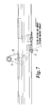
- FIG. 1 illustrates schematically a vehicle seat 1 in accordance with the present disclosure.
- the vehicle seat 1 includes a seat base 3, a seat back 2, a head rest 4, and a shoulder lever 5.
- the seat base 3 is provided a lower portion of the vehicle seat 1 taken in a vehicle height direction
- the seat base 3 is attached to the vehicle through lower supports (not illustrated).
- the seat base 3 being configured for an occupant to sit upon.
- the seat back 2 is attached to the seat base 3 at a lower portion of the seat back 2.
- the seat back 2 is rotatable relative to the seat base 3 so that the seat back 2 pivots in forward and rearward directions.
- Seat back 2 typically moves in a fore-aft direction of the vehicle.
- the seat back 2 is configured for an occupant to rest their back against.
- the head rest 4 protects the occupant from injury in the event of an accident.
- the seat back 2 also includes the shoulder lever 5 at the top portion thereof.
- the shoulder lever 5 is operable between a closed state and a released state.
- the shoulder lever 5 is an example of a walk-in release lever which begins a walk-in process for a user to enter or exit the vehicle.
- the shoulder lever 5 When the shoulder lever 5 is operated, the recliner lock is released. The release of the recliner 14 allows the seat back 2 to rotate. Accordingly, the seat back 2 is made to pivot forward toward the seat base 3 via a bias force provided by a spring.
- Figure 2 illustrates aspects of the middle walk-in return mechanism.
- the mechanism includes an inner side which corresponds to inner rail 21 and an outer side which corresponds to outer rail 20.
- Figures 2 , 3 , and 4 illustrate a rotation link 10 attached to a recliner link 11.
- the rotation link 10 pulls the recliner link 11. This movement is shown in Figure 5 by the recliner link 11 moving rightward in the figure.
- the recliner link 11 is attached at one end to the rotation link 10. At an opposite end of the recliner link 11, the recliner link 11 is attached to a slide release lever 12. The movement of the recliner link 11 by the rotation link 10 causes the slide release lever 12 to rotate downward around a pivot point, as shown by the dashed lines in Figure 3 .
- the slide release lever 12 includes a lock pin 18 which extends inward from the slide release lever 12.
- the lock pin 18 engages with a slide mechanism lock 23 which is part of the inner side of the seat 1.
- the downward rotation of the slide release lever 12, due to the recliner link 11 being pulled by the rotation link 10, causes the lock pin 18 to disengage the slide mechanism lock 23. Once the lock pin 18 has disengaged the slide mechanism lock 23, the inner side sliding mechanism is unlocked.
- the slide release lever 17 is on the outer side associated with outer rail 20.
- the slide release lever 17 includes a lock pin 19 which extends inward from the slide release lever 17.
- the lock pin 19 engages with a slide mechanism lock 24 as illustrated in Figures 5 and 8 .
- the downward rotation of the slide release lever 17 causes the lock pin 19 to disengage the slide mechanism lock 24.
- the outer side sliding mechanism is unlocked.
- Figure 5 illustrates the slide release levers 12 and 17 are connected by a center rotation tube 22. Any movement imparted to the slide release lever 12 by the recliner link 11 also moves the slide release lever 17 via the center rotation tube 22.
- the seat 1 is free to slide in the fore-aft direction. Once the slide mechanism is released form the locked state, a user may move the seat forward in the fore-aft direction in order to egress or ingress.
- a stopper link 13 is provided to the inner side of the seat 1.
- the stopper link 13 stops the movement of the track at a middle position, especially during the return of a walk-in process.
- the stopper link 13 includes a top portion 28 and bottom portion 26.
- the top portion 28 is configured to contact an end of the recliner link 11.
- the stopper link 13 is held in contact with the recliner link 11 by a bias force rotating the stopper link 13 toward the recliner link 11. Whereas the bottom portion 26 contacts a slide stopper 27 provided to the seat 1 on the inner side.
- the stopper link 13 also includes a middle portion 29 that is between the top portion 28 and the bottom portion 26.
- the middle portion 29 is configured to contact stopper 30 which is provided to the seat 1 on the inner side. Operation of the stopper link 13 will now be described in view of Figures 6 and 7 .
- the movement of the recliner link 11 causes the slide release levers 12 and 17 to release the respective inner and outer side slide mechanisms.
- the seat 1 is capable of traveling forward once the slide mechanism is released.
- Figure 4 shows the movement of the recliner link 11 rightward (dashed lines) based on the rotation of the rotation link 10 during the walk-in procedure.
- the stopper link 13 is held in contact with the recliner link 11 due to a bias force on the stopper link 13 causing a clockwise rotation of the stopper link 13 about axis 25.
- the recliner link 11 moves to release the slide release lever 12, the recliner link 11 begins to assert a force on the upper portion 28 of the stopper link 13.
- the continued movement of the recliner link 11 causes the stopper link 13 to rotate about the axis 25. Therefore, the stopper link 13 rotates down so that the lower portion 26 is operable to contact the slide stopper 27.
- the stopper link 13 is configured so that the stopper link 13 can slide over the slide stopper 27 (Shown in Figure 6 ), only when the seat is traveling in the forward direction. As shown in Figure 6 , the stopper link 13 has an inclined surface that allows the stopper link 13 to slide over the slide stopper 27. Once the stopper link 13 clears the slide stopper 27 the stopper link 13 returns to the fully down position.
- the seat begins at a forward position with regard to the slide mechanism, and a forward reclined position with regard to the recline mechanism.
- the user move the seat 1 rearward in the vehicle to return the seat to the middle or neutral position.
- FIG. 4 illustrates that the seat 1 is provided with a stopper 30 which contacts the middle portion 29 of the stopper link 13. The stopper 30 prevents further rotation of the stopper link 13 due to a bias force of a spring (not illustrated) on the seat back 2.
- the mechanism described in detail above can provide a middle return slide walk-in feature at a low cost and low mass. Relatively few parts are utilized to effect this function. Also, many of the parts are between the tracks and not visible from outside, less visible components being preferable to a vehicle buyer.
Landscapes
- Engineering & Computer Science (AREA)
- Aviation & Aerospace Engineering (AREA)
- Transportation (AREA)
- Mechanical Engineering (AREA)
- Seats For Vehicles (AREA)
Abstract
Description
- Exemplary aspects of the present invention relate to the recliner function of a vehicle seat and in particular to the recliner return walk in mechanism.
- Seats of a vehicle such as an automobile may be provided with a reclining mechanism that allows the seat back to pivot at a base portion thereof. One type of reclining mechanism allows the seat back to pivot to a forward position to allow the ingress and egress of passengers behind the seat. This reclining mechanism has several defined positions including: a neutral position, an upright position, a rear most position, and a front most position; where the ingress/egress of passengers behind occurs at the front most position.
- When a user desires to ingress or egress the vehicle a "walk-in" procedure is performed. Essentially, the seat back is brought forward via a reclining mechanism (recliner) system and then the seat is moved forward via a seat sliding mechanism. Once the seat has reached its forward-most position the user can more easily enter or exit a rear seat of the vehicle. An example of a walk-in procedure as described above is
U.S. patent application No. 13/667,495, filed on November 2, 2012 - When the egress/ingress is completed by the user, the walk-in procedure is reversed. The seat is moved rearward via the sliding mechanism and is stopped at neutral position in the fore-aft direction. Then the seat back is rotated back to an upright position and locked in place.
- A walk-in stopper mechanism is the mechanism that stops the rearward motion of the seat when moving via the sliding mechanism. The walk-in stopper mechanism prevents the seat from traveling rearward and facilitates the seat back returning to the upright position. However, the walk-in stopper mechanism is typically complicated and resides outside of the seat rails of the vehicle.
- Therefore, the invention relates to a slide return mechanism of a seat for a vehicle, the seat including a seat back and a seat base, the slide return mechanism including a recliner that reclines the seat back, a slide release lever that locks and unlocks the movement of a slide mechanism of the seat, and a stopper link. Rotation of the recliner causes the seat back to move downward, the slide release lever to unlock the slide mechanism, and the stopper link to move into position to prevent the seat from traveling in a rearward direction.
- In a particular embodiment, the slide return mechanism further comprises a recliner link that extends between the recliner and the slide release lever, wherein the rotation of the recliner moves the recliner link to cause the slide release lever to unlock.
- In a particular embodiment, the rotation of the recliner moves the recliner link to contact the stopper link to move the stopper link into position to prevent the seat from traveling in a rearward direction.
- In a particular embodiment, the slide return mechanism further comprises a slide stopper, wherein when the stopper link contacts the slide stopper during rearward movement of the seat, the seat stops traveling in the rearward direction and the seat back is brought upward thereby causing the slide release lever to lock the movement of the slide mechanism of the seat.
- In a particular embodiment, the upward movement of the seat back causes the recliner to rotate in a second direction which moves the recliner link to remove a force on the slide release lever to cause a bias force to move the slide release lever to lock the movement of the slide mechanism of the seat.
- A more complete appreciation of the invention and many of the attendant advantages thereof will be readily obtained as the same becomes better understood by reference to the following detailed description when considered in connection with the accompanying drawings, wherein:
-
Figure 1 illustrates a view of vehicle seat; -
Figure 2 illustrates an isometric view of a walk-in device in accordance with an exemplary aspect of the disclosure; -
Figure 3 illustrates a side view of a walk-in device in accordance with an exemplary aspect of the disclosure; -
Figure 4 illustrates a side view of a walk-in device in accordance with an exemplary aspect of the disclosure; -
Figure 5 illustrates an isometric view of a walk-in device in accordance with an exemplary aspect of the disclosure; -
Figure 6 illustrates a side view of a walk-in device in accordance with an exemplary aspect of the disclosure; -
Figure 7 illustrates a side view of a walk-in device in accordance with an exemplary aspect of the disclosure; -
Figure 8 illustrates a side view of a walk-in device in accordance with an exemplary aspect of the disclosure; - Referring now to the drawings, wherein like reference numerals designate identical or corresponding parts throughout the several views. Further, as used herein, the words "a," "an" and the like generally carry a meaning of "one or more," unless stated otherwise.
-
Figures 1-8 depict various aspects of a middle return slide walk-in mechanism for a vehicle seat. Here a vehicle refers to a land vehicle exemplified by an automobile. However, the present disclosure is also applicable to any similar type vehicle, such as but not limited to, a sport utility vehicle, a pickup truck, a commercial vehicle or the like. -
Figure 1 illustrates schematically a vehicle seat 1 in accordance with the present disclosure. The vehicle seat 1 includes aseat base 3, a seat back 2, a head rest 4, and ashoulder lever 5. Theseat base 3 is provided a lower portion of the vehicle seat 1 taken in a vehicle height direction Theseat base 3 is attached to the vehicle through lower supports (not illustrated). Theseat base 3 being configured for an occupant to sit upon. - The
seat back 2 is attached to theseat base 3 at a lower portion of theseat back 2. Theseat back 2 is rotatable relative to theseat base 3 so that the seat back 2 pivots in forward and rearward directions.Seat back 2 typically moves in a fore-aft direction of the vehicle. Theseat back 2 is configured for an occupant to rest their back against. - Attached at a top portion of the
seat back 2 is a head rest 4. The head rest 4 protects the occupant from injury in the event of an accident. - The
seat back 2 also includes theshoulder lever 5 at the top portion thereof. - The
shoulder lever 5 is operable between a closed state and a released state. - The
shoulder lever 5 is an example of a walk-in release lever which begins a walk-in process for a user to enter or exit the vehicle. When theshoulder lever 5 is operated, the recliner lock is released. The release of therecliner 14 allows the seat back 2 to rotate. Accordingly, theseat back 2 is made to pivot forward toward theseat base 3 via a bias force provided by a spring. -
Figure 2 illustrates aspects of the middle walk-in return mechanism. The mechanism includes an inner side which corresponds toinner rail 21 and an outer side which corresponds toouter rail 20. - Regarding the inner side,
Figures 2 ,3 , and4 illustrate arotation link 10 attached to arecliner link 11. When therecliner 14 is released and therotation link 10 is rotated by the seat back 3 a predetermined distance, then therotation link 10 pulls therecliner link 11. This movement is shown inFigure 5 by therecliner link 11 moving rightward in the figure. - The
recliner link 11 is attached at one end to therotation link 10. At an opposite end of therecliner link 11, therecliner link 11 is attached to aslide release lever 12. The movement of therecliner link 11 by therotation link 10 causes theslide release lever 12 to rotate downward around a pivot point, as shown by the dashed lines inFigure 3 . - Shown in
Figures 3 and5 , theslide release lever 12 includes alock pin 18 which extends inward from theslide release lever 12. Thelock pin 18 engages with aslide mechanism lock 23 which is part of the inner side of the seat 1. The downward rotation of theslide release lever 12, due to therecliner link 11 being pulled by therotation link 10, causes thelock pin 18 to disengage theslide mechanism lock 23. Once thelock pin 18 has disengaged theslide mechanism lock 23, the inner side sliding mechanism is unlocked. - Shown in
Figure 5 , theslide release lever 17 is on the outer side associated withouter rail 20. Theslide release lever 17 includes alock pin 19 which extends inward from theslide release lever 17. Thelock pin 19 engages with aslide mechanism lock 24 as illustrated inFigures 5 and8 . The downward rotation of theslide release lever 17 causes thelock pin 19 to disengage theslide mechanism lock 24. Once thelock pin 18 has disengaged theslide mechanism lock 24, the outer side sliding mechanism is unlocked. -
Figure 5 illustrates the slide release levers 12 and 17 are connected by acenter rotation tube 22. Any movement imparted to theslide release lever 12 by therecliner link 11 also moves theslide release lever 17 via thecenter rotation tube 22. When both the inner side and outer side sliding mechanisms are unlocked the seat 1 is free to slide in the fore-aft direction. Once the slide mechanism is released form the locked state, a user may move the seat forward in the fore-aft direction in order to egress or ingress. - As shown in
Figures 4 ,6 , and7 , astopper link 13 is provided to the inner side of the seat 1. Thestopper link 13 stops the movement of the track at a middle position, especially during the return of a walk-in process. Thestopper link 13 includes atop portion 28 andbottom portion 26. Thetop portion 28 is configured to contact an end of therecliner link 11. Thestopper link 13 is held in contact with therecliner link 11 by a bias force rotating thestopper link 13 toward therecliner link 11. Whereas thebottom portion 26 contacts aslide stopper 27 provided to the seat 1 on the inner side. - The
stopper link 13 also includes amiddle portion 29 that is between thetop portion 28 and thebottom portion 26. Themiddle portion 29 is configured to contactstopper 30 which is provided to the seat 1 on the inner side. Operation of thestopper link 13 will now be described in view ofFigures 6 and7 . - As described above the movement of the
recliner link 11 causes the slide release levers 12 and 17 to release the respective inner and outer side slide mechanisms. During the walk-in procedure, the seat 1 is capable of traveling forward once the slide mechanism is released. -
Figure 4 shows the movement of therecliner link 11 rightward (dashed lines) based on the rotation of therotation link 10 during the walk-in procedure. Thestopper link 13 is held in contact with therecliner link 11 due to a bias force on thestopper link 13 causing a clockwise rotation of thestopper link 13 aboutaxis 25. - As the
recliner link 11 moves to release theslide release lever 12, therecliner link 11 begins to assert a force on theupper portion 28 of thestopper link 13. The continued movement of therecliner link 11 causes thestopper link 13 to rotate about theaxis 25. Therefore, thestopper link 13 rotates down so that thelower portion 26 is operable to contact theslide stopper 27. - When slide mechanism of the seat 1 is release and the seat is begins sliding forward to permit the egress/ingress of the user, the
stopper link 13 is configured so that thestopper link 13 can slide over the slide stopper 27 (Shown inFigure 6 ), only when the seat is traveling in the forward direction. As shown inFigure 6 , thestopper link 13 has an inclined surface that allows thestopper link 13 to slide over theslide stopper 27. Once thestopper link 13 clears theslide stopper 27 thestopper link 13 returns to the fully down position. - After the user enters or exits the vehicle the walk-in return procedure is performed. The seat begins at a forward position with regard to the slide mechanism, and a forward reclined position with regard to the recline mechanism.
- Next, the user move the seat 1 rearward in the vehicle to return the seat to the middle or neutral position.
- When the seat 1 reaches the middle position, the
lower portion 26 of thestopper link 13 contacts theslide stopper 27, thereby causing the slide mechanism to stop its rearward progress (Shown inFigure 7 ).Figure 4 illustrates that the seat 1 is provided with astopper 30 which contacts themiddle portion 29 of thestopper link 13. Thestopper 30 prevents further rotation of thestopper link 13 due to a bias force of a spring (not illustrated) on the seat back 2. - When the rearward sliding motion is stopped by the
stopper link 13, the seat back 2 will rotate back to the upright position. The motion of the seat back 2 will rotate therotation link 10, which will cause therecliner link 11 to move in the opposite direction depicted inFigure 4 . This movement of therecliner link 11 releases downward force on theslide release lever 12. Therefore, the slide release levers 12 and 17 move upward due to a bias spring (not shown) and the respective lock pins 18 and 19 lock into position in the respective lock mechanisms. - Accordingly, the slide mechanism on the inner and outer sides of the seat are locked at the position determined by the
stopper link 13. - Therefore, the mechanism described in detail above can provide a middle return slide walk-in feature at a low cost and low mass. Relatively few parts are utilized to effect this function. Also, many of the parts are between the tracks and not visible from outside, less visible components being preferable to a vehicle buyer.
- Obviously, numerous modifications and variations of the present invention are possible in light of the above teachings. It is therefore to be understood that within the scope of the appended claims, the invention may be practiced otherwise than as specifically described herein.
Claims (5)
- A slide return mechanism of a seat for a vehicle, the seat (1) including a seat back (2) and a seat base (3), the slide return mechanism comprising:a recliner (14) that reclines the seat back (2);a slide release lever (12) that locks and unlocks the movement of a slide mechanism of the seat; anda stopper link (13),wherein rotation of the recliner (14) causes the seat back (2) to move downward, the slide release lever (12) to unlock the slide mechanism, and the stopper link (13) to move into position to prevent the seat (1) from traveling in a rearward direction at a predetermined position.
- The slide return mechanism according to claim 1, further comprising:a recliner link (11) that extends between the recliner (14) and the slide release lever (12), wherein the rotation of the recliner (14) moves the recliner link (11) to cause the slide release lever (12) to unlock.
- The slide return mechanism according to claim 2, wherein the rotation of the recliner (14) moves the recliner link (11) to contact the stopper link (13) to move the stopper link (13) into position to prevent the seat (1) from traveling in a rearward direction.
- The slide return mechanism according to claim 3, further comprising:a slide stopper (27), wherein when the stopper link (13) contacts the slide stopper (27) during rearward movement of the seat (1), the seat (1) stops traveling in the rearward direction and the seat back (2) is brought upward thereby causing the slide release lever (12) to lock the movement of the slide mechanism of the seat.
- The slide return mechanism according to claim 4, wherein the upward movement of the seat back (2) causes the recliner (14) to rotate in a second direction which moves the recliner link (11) to remove a force on the slide release lever to cause a bias force to move the slide release lever (12) to lock the movement of the slide mechanism of the seat.
Applications Claiming Priority (1)
| Application Number | Priority Date | Filing Date | Title |
|---|---|---|---|
| US13/916,222 US9108537B2 (en) | 2013-06-12 | 2013-06-12 | Vehicle seat apparatus with middle return slide walk in |
Publications (2)
| Publication Number | Publication Date |
|---|---|
| EP2815915A1 true EP2815915A1 (en) | 2014-12-24 |
| EP2815915B1 EP2815915B1 (en) | 2017-11-01 |
Family
ID=50774719
Family Applications (1)
| Application Number | Title | Priority Date | Filing Date |
|---|---|---|---|
| EP14169815.9A Not-in-force EP2815915B1 (en) | 2013-06-12 | 2014-05-26 | Vehicle seat apparatus with middle return slide walk in |
Country Status (3)
| Country | Link |
|---|---|
| US (1) | US9108537B2 (en) |
| EP (1) | EP2815915B1 (en) |
| JP (1) | JP5889936B2 (en) |
Families Citing this family (5)
| Publication number | Priority date | Publication date | Assignee | Title |
|---|---|---|---|---|
| JP6351362B2 (en) * | 2014-05-12 | 2018-07-04 | シロキ工業株式会社 | Seat slide device |
| CN104494471B (en) * | 2014-12-24 | 2016-06-29 | 重庆长安汽车股份有限公司 | A kind of adjusting mechanism for automobile seat |
| CN107020979A (en) * | 2017-05-31 | 2017-08-08 | 长春富维安道拓汽车饰件系统有限公司 | A kind of sliding rail unlocking mechanism of automotive seat |
| CN108202646A (en) * | 2018-01-31 | 2018-06-26 | 广州汽车集团零部件有限公司 | A kind of sliding rail of automobile seat unlocking mechanism |
| US11214180B1 (en) | 2019-09-23 | 2022-01-04 | Apple Inc. | Vehicle seat with reclining mechanism |
Citations (6)
| Publication number | Priority date | Publication date | Assignee | Title |
|---|---|---|---|---|
| DE102004042038A1 (en) * | 2004-08-31 | 2006-03-02 | Faurecia Autositze Gmbh & Co. Kg | Vehicle seat, has release and rest latches in positions facing each other in their displacement paths, where rest latch rests on easy-entry-stopper and rotates away while operating upper handle to fold backrest in cargo-position |
| WO2008035803A1 (en) * | 2006-09-19 | 2008-03-27 | Ts Tech Co., Ltd. | Arrangement lever device for automobile seat |
| WO2011041911A1 (en) * | 2009-10-08 | 2011-04-14 | Magna Seating Inc. | Sliding easy entry release mechanism with rest in full rear position |
| US20110127818A1 (en) * | 2009-12-01 | 2011-06-02 | Toyota Motor Engineering & Manufacturing | Seat assembly having dual actuated locking mechanism |
| WO2012096357A1 (en) * | 2011-01-14 | 2012-07-19 | アイシン精機 株式会社 | Seat reclining device and seat device |
| US20130113260A1 (en) * | 2011-11-04 | 2013-05-09 | Yasuhiro Kojima | Vehicle seat apparatus |
Family Cites Families (12)
| Publication number | Priority date | Publication date | Assignee | Title |
|---|---|---|---|---|
| FR2695885B1 (en) * | 1992-09-22 | 1994-12-02 | Faure Bertrand Automobile | Positioning slide for an internal memory seat cooperating with the fixed profile of the slide. |
| JP3467850B2 (en) * | 1994-07-04 | 2003-11-17 | アイシン精機株式会社 | Seat slide device |
| JP3653877B2 (en) * | 1996-07-31 | 2005-06-02 | アイシン精機株式会社 | Vehicle seat walk-in device |
| JP3560765B2 (en) * | 1997-05-13 | 2004-09-02 | 富士機工株式会社 | Seat slide device |
| US5899532A (en) | 1997-10-06 | 1999-05-04 | Excel Industries, Inc. | Easy entry seat track assembly with single point memory |
| CN1128728C (en) | 1998-11-05 | 2003-11-26 | 麦格纳座椅系统公司 | Easy entry mid-position memory seat |
| JP4120078B2 (en) | 1998-12-25 | 2008-07-16 | アイシン精機株式会社 | Walk-in device for vehicle seat |
| JP4103524B2 (en) * | 2002-09-30 | 2008-06-18 | アイシン精機株式会社 | Walk-in device for vehicle seat |
| CN1660625B (en) * | 2004-02-24 | 2010-05-05 | 爱信精机株式会社 | Seat sliding device for vehicle |
| DE102004038587B4 (en) * | 2004-08-06 | 2014-01-16 | Johnson Controls Gmbh | Device for the automatic locking of a component, in particular a vehicle seat and in particular in or on a vehicle and vehicle seat |
| JP5098279B2 (en) * | 2006-10-04 | 2012-12-12 | アイシン精機株式会社 | Vehicle seat device |
| JP2008247179A (en) * | 2007-03-30 | 2008-10-16 | Aisin Seiki Co Ltd | Vehicle seat device |
-
2013
- 2013-06-12 US US13/916,222 patent/US9108537B2/en not_active Expired - Fee Related
-
2014
- 2014-03-04 JP JP2014041792A patent/JP5889936B2/en not_active Expired - Fee Related
- 2014-05-26 EP EP14169815.9A patent/EP2815915B1/en not_active Not-in-force
Patent Citations (6)
| Publication number | Priority date | Publication date | Assignee | Title |
|---|---|---|---|---|
| DE102004042038A1 (en) * | 2004-08-31 | 2006-03-02 | Faurecia Autositze Gmbh & Co. Kg | Vehicle seat, has release and rest latches in positions facing each other in their displacement paths, where rest latch rests on easy-entry-stopper and rotates away while operating upper handle to fold backrest in cargo-position |
| WO2008035803A1 (en) * | 2006-09-19 | 2008-03-27 | Ts Tech Co., Ltd. | Arrangement lever device for automobile seat |
| WO2011041911A1 (en) * | 2009-10-08 | 2011-04-14 | Magna Seating Inc. | Sliding easy entry release mechanism with rest in full rear position |
| US20110127818A1 (en) * | 2009-12-01 | 2011-06-02 | Toyota Motor Engineering & Manufacturing | Seat assembly having dual actuated locking mechanism |
| WO2012096357A1 (en) * | 2011-01-14 | 2012-07-19 | アイシン精機 株式会社 | Seat reclining device and seat device |
| US20130113260A1 (en) * | 2011-11-04 | 2013-05-09 | Yasuhiro Kojima | Vehicle seat apparatus |
Also Published As
| Publication number | Publication date |
|---|---|
| US9108537B2 (en) | 2015-08-18 |
| EP2815915B1 (en) | 2017-11-01 |
| JP5889936B2 (en) | 2016-03-22 |
| JP2015000719A (en) | 2015-01-05 |
| US20140368013A1 (en) | 2014-12-18 |
Similar Documents
| Publication | Publication Date | Title |
|---|---|---|
| US10479232B2 (en) | Passenger support and methods of use | |
| US6899392B1 (en) | Stadium slide seat | |
| EP2815915B1 (en) | Vehicle seat apparatus with middle return slide walk in | |
| CN102905934B (en) | Easy-entry seating system with individual position memory and hold-open features | |
| US10065536B2 (en) | Reclining seat for a vehicle | |
| JP5169146B2 (en) | Vehicle seat device | |
| US10406946B2 (en) | Vehicle seat | |
| US9073458B2 (en) | Vehicle seat apparatus | |
| EP2939872B1 (en) | Power seat with complete manual walk-in system | |
| US9573490B1 (en) | Reclining seat for a vehicle | |
| US8757722B2 (en) | Seat assembly with easy-entry mechanism and fold flat feature | |
| JP5109543B2 (en) | Vehicle seat | |
| KR101345678B1 (en) | Motor vehicle seat and method for transferring a seatback from the use position to a stowed position | |
| CN105793100B (en) | Pivot forward and seat suitable for seat | |
| US10710474B2 (en) | Passenger support | |
| US9061606B2 (en) | Electric release manual seat | |
| US9156377B2 (en) | Power seat with complete manual walk-in system | |
| EP3393848B1 (en) | A latching device and a slouch seat including the latching device | |
| JP2018161924A (en) | Underfloor storage device | |
| EP2829435B1 (en) | Seat with complete manual walk-in system | |
| JP2009035197A (en) | Vehicular seat | |
| KR101262683B1 (en) | Front seat operation device of 3 door automobile |
Legal Events
| Date | Code | Title | Description |
|---|---|---|---|
| PUAI | Public reference made under article 153(3) epc to a published international application that has entered the european phase |
Free format text: ORIGINAL CODE: 0009012 |
|
| 17P | Request for examination filed |
Effective date: 20140526 |
|
| AK | Designated contracting states |
Kind code of ref document: A1 Designated state(s): AL AT BE BG CH CY CZ DE DK EE ES FI FR GB GR HR HU IE IS IT LI LT LU LV MC MK MT NL NO PL PT RO RS SE SI SK SM TR |
|
| AX | Request for extension of the european patent |
Extension state: BA ME |
|
| R17P | Request for examination filed (corrected) |
Effective date: 20150427 |
|
| RBV | Designated contracting states (corrected) |
Designated state(s): AL AT BE BG CH CY CZ DE DK EE ES FI FR GB GR HR HU IE IS IT LI LT LU LV MC MK MT NL NO PL PT RO RS SE SI SK SM TR |
|
| GRAP | Despatch of communication of intention to grant a patent |
Free format text: ORIGINAL CODE: EPIDOSNIGR1 |
|
| STAA | Information on the status of an ep patent application or granted ep patent |
Free format text: STATUS: GRANT OF PATENT IS INTENDED |
|
| INTG | Intention to grant announced |
Effective date: 20170531 |
|
| GRAS | Grant fee paid |
Free format text: ORIGINAL CODE: EPIDOSNIGR3 |
|
| GRAA | (expected) grant |
Free format text: ORIGINAL CODE: 0009210 |
|
| STAA | Information on the status of an ep patent application or granted ep patent |
Free format text: STATUS: THE PATENT HAS BEEN GRANTED |
|
| AK | Designated contracting states |
Kind code of ref document: B1 Designated state(s): AL AT BE BG CH CY CZ DE DK EE ES FI FR GB GR HR HU IE IS IT LI LT LU LV MC MK MT NL NO PL PT RO RS SE SI SK SM TR |
|
| REG | Reference to a national code |
Ref country code: GB Ref legal event code: FG4D |
|
| REG | Reference to a national code |
Ref country code: CH Ref legal event code: EP Ref country code: AT Ref legal event code: REF Ref document number: 941693 Country of ref document: AT Kind code of ref document: T Effective date: 20171115 |
|
| REG | Reference to a national code |
Ref country code: IE Ref legal event code: FG4D |
|
| REG | Reference to a national code |
Ref country code: DE Ref legal event code: R096 Ref document number: 602014016466 Country of ref document: DE |
|
| REG | Reference to a national code |
Ref country code: NL Ref legal event code: MP Effective date: 20171101 |
|
| REG | Reference to a national code |
Ref country code: LT Ref legal event code: MG4D |
|
| REG | Reference to a national code |
Ref country code: FR Ref legal event code: PLFP Year of fee payment: 5 |
|
| REG | Reference to a national code |
Ref country code: AT Ref legal event code: MK05 Ref document number: 941693 Country of ref document: AT Kind code of ref document: T Effective date: 20171101 |
|
| PG25 | Lapsed in a contracting state [announced via postgrant information from national office to epo] |
Ref country code: NO Free format text: LAPSE BECAUSE OF FAILURE TO SUBMIT A TRANSLATION OF THE DESCRIPTION OR TO PAY THE FEE WITHIN THE PRESCRIBED TIME-LIMIT Effective date: 20180201 Ref country code: SE Free format text: LAPSE BECAUSE OF FAILURE TO SUBMIT A TRANSLATION OF THE DESCRIPTION OR TO PAY THE FEE WITHIN THE PRESCRIBED TIME-LIMIT Effective date: 20171101 Ref country code: NL Free format text: LAPSE BECAUSE OF FAILURE TO SUBMIT A TRANSLATION OF THE DESCRIPTION OR TO PAY THE FEE WITHIN THE PRESCRIBED TIME-LIMIT Effective date: 20171101 Ref country code: FI Free format text: LAPSE BECAUSE OF FAILURE TO SUBMIT A TRANSLATION OF THE DESCRIPTION OR TO PAY THE FEE WITHIN THE PRESCRIBED TIME-LIMIT Effective date: 20171101 Ref country code: ES Free format text: LAPSE BECAUSE OF FAILURE TO SUBMIT A TRANSLATION OF THE DESCRIPTION OR TO PAY THE FEE WITHIN THE PRESCRIBED TIME-LIMIT Effective date: 20171101 Ref country code: LT Free format text: LAPSE BECAUSE OF FAILURE TO SUBMIT A TRANSLATION OF THE DESCRIPTION OR TO PAY THE FEE WITHIN THE PRESCRIBED TIME-LIMIT Effective date: 20171101 |
|
| PG25 | Lapsed in a contracting state [announced via postgrant information from national office to epo] |
Ref country code: IS Free format text: LAPSE BECAUSE OF FAILURE TO SUBMIT A TRANSLATION OF THE DESCRIPTION OR TO PAY THE FEE WITHIN THE PRESCRIBED TIME-LIMIT Effective date: 20180301 Ref country code: GR Free format text: LAPSE BECAUSE OF FAILURE TO SUBMIT A TRANSLATION OF THE DESCRIPTION OR TO PAY THE FEE WITHIN THE PRESCRIBED TIME-LIMIT Effective date: 20180202 Ref country code: BG Free format text: LAPSE BECAUSE OF FAILURE TO SUBMIT A TRANSLATION OF THE DESCRIPTION OR TO PAY THE FEE WITHIN THE PRESCRIBED TIME-LIMIT Effective date: 20180201 Ref country code: RS Free format text: LAPSE BECAUSE OF FAILURE TO SUBMIT A TRANSLATION OF THE DESCRIPTION OR TO PAY THE FEE WITHIN THE PRESCRIBED TIME-LIMIT Effective date: 20171101 Ref country code: LV Free format text: LAPSE BECAUSE OF FAILURE TO SUBMIT A TRANSLATION OF THE DESCRIPTION OR TO PAY THE FEE WITHIN THE PRESCRIBED TIME-LIMIT Effective date: 20171101 Ref country code: AT Free format text: LAPSE BECAUSE OF FAILURE TO SUBMIT A TRANSLATION OF THE DESCRIPTION OR TO PAY THE FEE WITHIN THE PRESCRIBED TIME-LIMIT Effective date: 20171101 Ref country code: HR Free format text: LAPSE BECAUSE OF FAILURE TO SUBMIT A TRANSLATION OF THE DESCRIPTION OR TO PAY THE FEE WITHIN THE PRESCRIBED TIME-LIMIT Effective date: 20171101 |
|
| PG25 | Lapsed in a contracting state [announced via postgrant information from national office to epo] |
Ref country code: CZ Free format text: LAPSE BECAUSE OF FAILURE TO SUBMIT A TRANSLATION OF THE DESCRIPTION OR TO PAY THE FEE WITHIN THE PRESCRIBED TIME-LIMIT Effective date: 20171101 Ref country code: SK Free format text: LAPSE BECAUSE OF FAILURE TO SUBMIT A TRANSLATION OF THE DESCRIPTION OR TO PAY THE FEE WITHIN THE PRESCRIBED TIME-LIMIT Effective date: 20171101 Ref country code: CY Free format text: LAPSE BECAUSE OF FAILURE TO SUBMIT A TRANSLATION OF THE DESCRIPTION OR TO PAY THE FEE WITHIN THE PRESCRIBED TIME-LIMIT Effective date: 20171101 Ref country code: EE Free format text: LAPSE BECAUSE OF FAILURE TO SUBMIT A TRANSLATION OF THE DESCRIPTION OR TO PAY THE FEE WITHIN THE PRESCRIBED TIME-LIMIT Effective date: 20171101 Ref country code: DK Free format text: LAPSE BECAUSE OF FAILURE TO SUBMIT A TRANSLATION OF THE DESCRIPTION OR TO PAY THE FEE WITHIN THE PRESCRIBED TIME-LIMIT Effective date: 20171101 |
|
| PGFP | Annual fee paid to national office [announced via postgrant information from national office to epo] |
Ref country code: DE Payment date: 20180515 Year of fee payment: 5 |
|
| REG | Reference to a national code |
Ref country code: DE Ref legal event code: R097 Ref document number: 602014016466 Country of ref document: DE |
|
| PG25 | Lapsed in a contracting state [announced via postgrant information from national office to epo] |
Ref country code: RO Free format text: LAPSE BECAUSE OF FAILURE TO SUBMIT A TRANSLATION OF THE DESCRIPTION OR TO PAY THE FEE WITHIN THE PRESCRIBED TIME-LIMIT Effective date: 20171101 Ref country code: IT Free format text: LAPSE BECAUSE OF FAILURE TO SUBMIT A TRANSLATION OF THE DESCRIPTION OR TO PAY THE FEE WITHIN THE PRESCRIBED TIME-LIMIT Effective date: 20171101 Ref country code: PL Free format text: LAPSE BECAUSE OF FAILURE TO SUBMIT A TRANSLATION OF THE DESCRIPTION OR TO PAY THE FEE WITHIN THE PRESCRIBED TIME-LIMIT Effective date: 20171101 Ref country code: SM Free format text: LAPSE BECAUSE OF FAILURE TO SUBMIT A TRANSLATION OF THE DESCRIPTION OR TO PAY THE FEE WITHIN THE PRESCRIBED TIME-LIMIT Effective date: 20171101 |
|
| PGFP | Annual fee paid to national office [announced via postgrant information from national office to epo] |
Ref country code: FR Payment date: 20180411 Year of fee payment: 5 |
|
| PLBE | No opposition filed within time limit |
Free format text: ORIGINAL CODE: 0009261 |
|
| STAA | Information on the status of an ep patent application or granted ep patent |
Free format text: STATUS: NO OPPOSITION FILED WITHIN TIME LIMIT |
|
| 26N | No opposition filed |
Effective date: 20180802 |
|
| PG25 | Lapsed in a contracting state [announced via postgrant information from national office to epo] |
Ref country code: SI Free format text: LAPSE BECAUSE OF FAILURE TO SUBMIT A TRANSLATION OF THE DESCRIPTION OR TO PAY THE FEE WITHIN THE PRESCRIBED TIME-LIMIT Effective date: 20171101 |
|
| REG | Reference to a national code |
Ref country code: CH Ref legal event code: PL |
|
| GBPC | Gb: european patent ceased through non-payment of renewal fee |
Effective date: 20180526 |
|
| REG | Reference to a national code |
Ref country code: BE Ref legal event code: MM Effective date: 20180531 |
|
| PG25 | Lapsed in a contracting state [announced via postgrant information from national office to epo] |
Ref country code: MC Free format text: LAPSE BECAUSE OF FAILURE TO SUBMIT A TRANSLATION OF THE DESCRIPTION OR TO PAY THE FEE WITHIN THE PRESCRIBED TIME-LIMIT Effective date: 20171101 |
|
| REG | Reference to a national code |
Ref country code: IE Ref legal event code: MM4A |
|
| PG25 | Lapsed in a contracting state [announced via postgrant information from national office to epo] |
Ref country code: LI Free format text: LAPSE BECAUSE OF NON-PAYMENT OF DUE FEES Effective date: 20180531 Ref country code: CH Free format text: LAPSE BECAUSE OF NON-PAYMENT OF DUE FEES Effective date: 20180531 |
|
| PG25 | Lapsed in a contracting state [announced via postgrant information from national office to epo] |
Ref country code: LU Free format text: LAPSE BECAUSE OF NON-PAYMENT OF DUE FEES Effective date: 20180526 |
|
| PG25 | Lapsed in a contracting state [announced via postgrant information from national office to epo] |
Ref country code: IE Free format text: LAPSE BECAUSE OF NON-PAYMENT OF DUE FEES Effective date: 20180526 Ref country code: GB Free format text: LAPSE BECAUSE OF NON-PAYMENT OF DUE FEES Effective date: 20180526 |
|
| PG25 | Lapsed in a contracting state [announced via postgrant information from national office to epo] |
Ref country code: BE Free format text: LAPSE BECAUSE OF NON-PAYMENT OF DUE FEES Effective date: 20180531 |
|
| REG | Reference to a national code |
Ref country code: DE Ref legal event code: R119 Ref document number: 602014016466 Country of ref document: DE |
|
| PG25 | Lapsed in a contracting state [announced via postgrant information from national office to epo] |
Ref country code: MT Free format text: LAPSE BECAUSE OF NON-PAYMENT OF DUE FEES Effective date: 20180526 |
|
| PG25 | Lapsed in a contracting state [announced via postgrant information from national office to epo] |
Ref country code: TR Free format text: LAPSE BECAUSE OF FAILURE TO SUBMIT A TRANSLATION OF THE DESCRIPTION OR TO PAY THE FEE WITHIN THE PRESCRIBED TIME-LIMIT Effective date: 20171101 |
|
| PG25 | Lapsed in a contracting state [announced via postgrant information from national office to epo] |
Ref country code: DE Free format text: LAPSE BECAUSE OF NON-PAYMENT OF DUE FEES Effective date: 20191203 |
|
| PG25 | Lapsed in a contracting state [announced via postgrant information from national office to epo] |
Ref country code: PT Free format text: LAPSE BECAUSE OF FAILURE TO SUBMIT A TRANSLATION OF THE DESCRIPTION OR TO PAY THE FEE WITHIN THE PRESCRIBED TIME-LIMIT Effective date: 20171101 Ref country code: HU Free format text: LAPSE BECAUSE OF FAILURE TO SUBMIT A TRANSLATION OF THE DESCRIPTION OR TO PAY THE FEE WITHIN THE PRESCRIBED TIME-LIMIT; INVALID AB INITIO Effective date: 20140526 |
|
| PG25 | Lapsed in a contracting state [announced via postgrant information from national office to epo] |
Ref country code: FR Free format text: LAPSE BECAUSE OF NON-PAYMENT OF DUE FEES Effective date: 20190531 Ref country code: MK Free format text: LAPSE BECAUSE OF NON-PAYMENT OF DUE FEES Effective date: 20171101 |
|
| PG25 | Lapsed in a contracting state [announced via postgrant information from national office to epo] |
Ref country code: AL Free format text: LAPSE BECAUSE OF FAILURE TO SUBMIT A TRANSLATION OF THE DESCRIPTION OR TO PAY THE FEE WITHIN THE PRESCRIBED TIME-LIMIT Effective date: 20171101 |