EP2815775A1 - Biological fluid filters with port for optimized flow distribution - Google Patents
Biological fluid filters with port for optimized flow distribution Download PDFInfo
- Publication number
- EP2815775A1 EP2815775A1 EP13193605.6A EP13193605A EP2815775A1 EP 2815775 A1 EP2815775 A1 EP 2815775A1 EP 13193605 A EP13193605 A EP 13193605A EP 2815775 A1 EP2815775 A1 EP 2815775A1
- Authority
- EP
- European Patent Office
- Prior art keywords
- port
- chamber
- walls
- defining
- housing
- Prior art date
- Legal status (The legal status is an assumption and is not a legal conclusion. Google has not performed a legal analysis and makes no representation as to the accuracy of the status listed.)
- Granted
Links
Images

Classifications
-
- A—HUMAN NECESSITIES
- A61—MEDICAL OR VETERINARY SCIENCE; HYGIENE
- A61M—DEVICES FOR INTRODUCING MEDIA INTO, OR ONTO, THE BODY; DEVICES FOR TRANSDUCING BODY MEDIA OR FOR TAKING MEDIA FROM THE BODY; DEVICES FOR PRODUCING OR ENDING SLEEP OR STUPOR
- A61M1/00—Suction or pumping devices for medical purposes; Devices for carrying-off, for treatment of, or for carrying-over, body-liquids; Drainage systems
- A61M1/34—Filtering material out of the blood by passing it through a membrane, i.e. hemofiltration or diafiltration
-
- A—HUMAN NECESSITIES
- A61—MEDICAL OR VETERINARY SCIENCE; HYGIENE
- A61M—DEVICES FOR INTRODUCING MEDIA INTO, OR ONTO, THE BODY; DEVICES FOR TRANSDUCING BODY MEDIA OR FOR TAKING MEDIA FROM THE BODY; DEVICES FOR PRODUCING OR ENDING SLEEP OR STUPOR
- A61M1/00—Suction or pumping devices for medical purposes; Devices for carrying-off, for treatment of, or for carrying-over, body-liquids; Drainage systems
- A61M1/36—Other treatment of blood in a by-pass of the natural circulatory system, e.g. temperature adaptation, irradiation ; Extra-corporeal blood circuits
- A61M1/3621—Extra-corporeal blood circuits
- A61M1/3627—Degassing devices; Buffer reservoirs; Drip chambers; Blood filters
- A61M1/3633—Blood component filters, e.g. leukocyte filters
-
- A—HUMAN NECESSITIES
- A61—MEDICAL OR VETERINARY SCIENCE; HYGIENE
- A61M—DEVICES FOR INTRODUCING MEDIA INTO, OR ONTO, THE BODY; DEVICES FOR TRANSDUCING BODY MEDIA OR FOR TAKING MEDIA FROM THE BODY; DEVICES FOR PRODUCING OR ENDING SLEEP OR STUPOR
- A61M1/00—Suction or pumping devices for medical purposes; Devices for carrying-off, for treatment of, or for carrying-over, body-liquids; Drainage systems
- A61M1/02—Blood transfusion apparatus
- A61M1/0209—Multiple bag systems for separating or storing blood components
- A61M1/0218—Multiple bag systems for separating or storing blood components with filters
-
- A—HUMAN NECESSITIES
- A61—MEDICAL OR VETERINARY SCIENCE; HYGIENE
- A61M—DEVICES FOR INTRODUCING MEDIA INTO, OR ONTO, THE BODY; DEVICES FOR TRANSDUCING BODY MEDIA OR FOR TAKING MEDIA FROM THE BODY; DEVICES FOR PRODUCING OR ENDING SLEEP OR STUPOR
- A61M1/00—Suction or pumping devices for medical purposes; Devices for carrying-off, for treatment of, or for carrying-over, body-liquids; Drainage systems
- A61M1/34—Filtering material out of the blood by passing it through a membrane, i.e. hemofiltration or diafiltration
- A61M1/3403—Regulation parameters
- A61M1/3406—Physical characteristics of the filtrate, e.g. urea
-
- A—HUMAN NECESSITIES
- A61—MEDICAL OR VETERINARY SCIENCE; HYGIENE
- A61M—DEVICES FOR INTRODUCING MEDIA INTO, OR ONTO, THE BODY; DEVICES FOR TRANSDUCING BODY MEDIA OR FOR TAKING MEDIA FROM THE BODY; DEVICES FOR PRODUCING OR ENDING SLEEP OR STUPOR
- A61M1/00—Suction or pumping devices for medical purposes; Devices for carrying-off, for treatment of, or for carrying-over, body-liquids; Drainage systems
- A61M1/36—Other treatment of blood in a by-pass of the natural circulatory system, e.g. temperature adaptation, irradiation ; Extra-corporeal blood circuits
- A61M1/3621—Extra-corporeal blood circuits
- A61M1/3627—Degassing devices; Buffer reservoirs; Drip chambers; Blood filters
- A61M1/3633—Blood component filters, e.g. leukocyte filters
- A61M1/3635—Constructional details
-
- A—HUMAN NECESSITIES
- A61—MEDICAL OR VETERINARY SCIENCE; HYGIENE
- A61M—DEVICES FOR INTRODUCING MEDIA INTO, OR ONTO, THE BODY; DEVICES FOR TRANSDUCING BODY MEDIA OR FOR TAKING MEDIA FROM THE BODY; DEVICES FOR PRODUCING OR ENDING SLEEP OR STUPOR
- A61M2206/00—Characteristics of a physical parameter; associated device therefor
- A61M2206/10—Flow characteristics
- A61M2206/20—Flow characteristics having means for promoting or enhancing the flow, actively or passively
Definitions
- the present disclosure is directed to removal devices for processing biological fluids and removing unwanted components or agents therefrom. More particularly, the present disclosure is directed to removal devices such as filters for processing biological fluids having ports that optimize flow distribution in the removal medium.
- Removal devices are commonly used in the medical field to remove unwanted components from a biological fluid.
- leukocytes white blood cells
- the removal device includes a filter medium that has pores sized and distributed to prevent the passage of leukocytes, thus providing a biological fluid that is substantially free of leukocytes.
- the biological fluid enters the filter through an inlet port and flows through a filter medium.
- the filter medium for leukoreduction
- the filter medium includes a plurality of sheets made of melt-blown, non-woven fibers which provide a network of pores and torturous path through which the biological fluid must pass.
- the filter (or other removal device) includes an outlet port on the opposite side of the medium through which the biological fluid exits the device.
- it is desirable that the fluid is well distributed across the membrane.
- the present disclosure is directed to a device for removing unwanted cells from a biological fluid.
- the device includes a housing including a pair of walls defining a chamber between the walls and a removal medium within the chamber.
- the device further includes an inlet port carried by one of the pair of walls and an outlet port carried by the other of the pair of walls. At least one of the ports defines a flow path that includes a chamber-communicating portion that has a cross-section larger than the cross-section of an adjacent portion of the flow path within the port.
- Figure 1 is a plan view of a representative filter in accordance with the present disclosure
- Figure 2 is a side view of the filter of Fig. 1 ;
- Figure 3 is an enlarged cross-sectional view of one embodiment of a filter port in accordance with the present disclosure
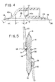
- Figure 4 is an enlarged cross-sectional side view of another embodiment of a filter port in accordance with the present disclosure.
- Figure 5 is a cross-sectional side view of a filter device of the present disclosure showing the distribution of flow across the filter medium.
- Fig. 1 shows a representative removal device in accordance with the present disclosure. While the devices described herein are particularly well-suited for leukoreduction, it will be understood that the present disclosure is not limited to the removal of any one component from any one biological fluid. The removal devices described herein may be used wherever it is desired to remove a component or an agent from a biological fluid.
- Device 10 is suited for removal of selected components from a biological fluid such as blood.
- Device 10 includes housing 12, which includes outer walls 14 and 16.
- Housing 12 is preferably made of a biocompatible material that is also sterilizable using conventional sterilization techniques commonly used in the assembly of disposable blood processing sets, such as steam sterilization or radiation sterilization.
- housing walls 14, 16 may be made of a rigid, polymeric material sealed together at or near the periphery thereof. The sealing of walls 14, 16 may be achieved by adhesive, welding or other forms of attachment.
- housing walls 14 and 16 may be made of a soft, flexible polymeric material.
- suitable polymeric materials include any flexible material such as, but not limited to polyvinyl chloride.
- housing walls may be sealed along their peripheral edges to form a seal 18.
- an additional inner peripheral seal may also be provided, as described in Patent Application Publication US 2002/0113/0113003 , the contents of which is incorporated herein by reference. Seal 18 and inner peripheral seal define a cushioned peripheral portion (not shown).
- walls 14 and 16 may include inlet and outlet ports 24 and 26, respectively. Ports 24 and 26 communicate with an internal chamber 28, defined by walls 14 and 16. Ports 24 and 26 may be carried by walls 14 and 16, as shown in Figs. 1 and 2 . Ports 24 and 26 may be separately attached to housing walls 14, 16 or integrally molded with housing walls 14 and 16. Ports 24, 26 may be made of any suitable material such as, but not limited to, polyvinyl chloride (PVC). A material having a 77 shore A durometer (+/-10) may be preferred. As shown in Figs. 1 and 2 , the inlet and outlet ports may be located in diametrically opposed locations on walls 14 and 16.
- PVC polyvinyl chloride
- inlet port 24 may be positioned closer to the "top" peripheral edge of filter 10 on wall 14, whereas outlet port 26 may be positioned closer to the "bottom” peripheral edge of filter 10 and wall 16.
- ports 24 and 26 may be modified or otherwise provided.
- Ports 24 and 26 define internal flow paths which establish fluid communication between interior chamber 28 ( Fig. 5 ) and joined tubing 20 that leads to other containers or parts of a disposable fluid processing set in which filter 10 is included.
- chamber 28 accommodates a filter medium 30.
- filter medium 30 may be provided as a pad that includes a plurality of pores sized to prevent passage of leukocytes and/or other unwanted components while allowing other blood components to pass.
- filter medium 30 may include a plurality of sheets wherein each sheet includes pores of a desired diameter and/or size and distribution.
- sheets may be made of melt blown, non-woven fibers. Fibers may be made of a suitable polymeric material, such as polyester, or a polyolefin, such as polyethylene or polypropylene. Depending, in part, on the application, removal medium 30 may also be made of woven fabric or a composite polymeric material.
- removal medium 30 may be made of a plurality of melt blown, non-woven fiber sheets.
- groups of sheets may provide filter medium with filter portions selected to perform particular functions.
- filter medium 30 may include a filter portion closest to housing wall 14 (carrying inlet port 24) made up of a plurality of sheets to provide a "pre-filter.” Downstream of the pre-filter, device 10 may include the "main" filter portion which may include a plurality of sheets of selected porosity. A filter portion downstream of the main filter may provide for filtration of additional components and/or provide a spacer element for the filter medium 30.
- port 24 includes a flow path 41 defined by port wall 40.
- Flow path 41 may include a chamber-communicating portion 46 that is adjacent to chamber 28 and directs flow into chamber 28 and removal medium 30 contained therein.
- Flow path 41 may have a variable diameter or cross-section between tube receiving portion 43 (i.e., the portion that receives tubing 20) and chamber 28, as defined by the thickness of port wall 40.
- portion 46 of flow path 41 may have a greater cross-section or diameter d 1 than the cross-section or diameter d 2 at a portion of the flow path adjacent to portion 42 and (in the case of inlet port 24) upstream of portion 46.
- chamber-communicating portion 46 may have a larger cross-section than adjacent flow path portion 42 downstream of portion 46.
- port walls 40a and 40b flare outwardly relative to axes 50 and 50', which axes are generally perpendicular to housing wall 14 and the outer surface 31 of filter medium 30. In one embodiment, walls 40a and 40b flare outwardly relative to axes 50 and 50' by angles ⁇ and ⁇ , respectively.
- angles formed between flared walls 40a and 40b and axes 50 and 50' may be anywhere between 10-89° and, more preferably, may be between about 20-60°.
- the degree of outward flare i.e., angles ⁇ and ⁇
- the diameter of the port opening at the chamber-communicating portion as defined by the flared walls 40a and 40b may be between about 0.25 to 2.0 cm.
- one of walls 40a and 40b may flare outwardly more than the other to provide an asymmetrical or non-symmetrical opening at portion 46, as shown, for example, in Fig. 4 .
- An asymmetrical or non-symmetrical opening may be desirable where port 24 is not centrally located on filter housing wall 14 (or 16) but is, instead, nearer the "top" (or "bottom") edge of filter 10.
- An asymmetrical opening where port wall 40a flares outwardly to a greater degree toward the "bottom" edge than the top edge of filter 10 may allow for greater distribution of fluid within filter medium 30.
- ports 24 and 26 may include a structure as described above and that the discussion above, while in the context of port 24, may apply equally to port 26. Alternatively, only one of the ports may be so structured. Thus, in one embodiment, one of ports 24 or 26 may include symmetrically flared port walls 40a and 40b resulting in a wider flow path while the other port may be non-flared with walls that are generally perpendicular relative to the outer housing wall 14.
- one of ports 24 or 26 may have an asymmetrical or non-symmetrical flared wall as described above and shown in Fig. 4 , while the other of the ports has no flare whatsoever.
- one of ports 24 or 26 may have an asymmetrical opening in communication with the chamber 28 defined by asymmetrically flared walls 40a and 40b, while the other of the ports has symmetrical flared walls 40a and 40b, as shown in Fig. 3 .
- both of the port openings may be either symmetrically or asymmetrically flared, as described above.
- a device for removing unwanted cells from a biological fluid includes a housing that includes a pair of walls defining a chamber between the walls.
- a removal medium is located within the chamber and an inlet port is carried by one of the walls and an outlet port is carried by the other of the walls.
- At least one of the ports defines a flow path that has a chamber-communicating portion.
- the chamber-communicating portion has a cross-section that is larger than the cross-section of an adjacent portion of the flow path.
- a second aspect of the present subject matter includes the above-described device wherein at least one port includes a wall defining the flow path portions.
- a third aspect of the present subject matter includes a device in accordance with any one of the first or second aspects described above wherein the port wall defining the chamber-communicating portion flares outwardly relative to an axis that is substantially perpendicular to the housing wall.
- a fourth aspect of the subject matter described herein includes a device in accordance with any one of the first through third aspects described above, wherein the port wall defining the chamber-communicating portion flares outwardly substantially symmetrically.
- a fifth aspect of the present subject matter includes the device in accordance with any one of the first through fourth aspects described above wherein the housing has a top end and a bottom end and wherein one of the ports is closer to the top end and the other of the ports is closer to the bottom end.
- a sixth aspect of the present subject matter includes a device in accordance with any one of the first through fifth aspects described above wherein each of the ports includes a wall defining the flow path portions.
- a seventh aspect of the present subject matter includes a device in accordance with any one of the first through sixth aspects described above wherein the port walls of at least one of the ports defining the chamber-communicating portions flares outwardly relative to an axis that is substantially perpendicular to the housing wall.
- An eighth aspect of the present subject matter includes a device in accordance with any one of the second through seventh aspects described above wherein the port wall defines a chamber-communicating portion that flares outwardly substantially symmetrically.
- a ninth aspect of the present subject matter includes a device in accordance with any one of the above-described second through seventh aspects wherein the port walls defining the chamber-communicating portion flare outwardly non-symmetrically.
- a tenth aspect of the present subject matter includes a device in accordance with any one of the fifth through sixth aspects described above wherein the port nearer the top portion of the housing includes a port wall defining a chamber-communicating portion and wherein the port wall flares outwardly to a greater degree toward the bottom end than toward the top end of the housing.
- An eleventh aspect of the present subject matter includes a device in accordance with any one of the first through tenth aspects described above wherein the port nearer the bottom end of the housing includes a port wall defining a chamber-communicating portion wherein the port flares outwardly to a greater degree toward the top end of the housing than toward the bottom end of the housing.
- a twelfth aspect of the present subject matter includes a device in accordance with any one of the first through eleventh aspects described above wherein the housing walls are made of a flexible material.
- a thirteenth aspect of the present subject matter includes a device in accordance with any one of the first through twelfth aspects described above wherein the ports are integrally molded with the housing walls.
- a fourteenth aspect of the present subject matter includes a device in accordance with any one of the first through thirteenth aspects described above wherein the ports are separately molded and separately attached to the housing walls.
- a fifthteenth aspect of the present subject matter includes a device in accordance with any one of the first through fourteenth aspects described above wherein the removal medium comprises a filter of non-woven fibers.
- a sixteenth aspect of the present subject matter includes a device in accordance with any one of the first through fifteenth aspects described above wherein the removal medium includes a plurality of layers of non-woven fibers.
- a seventeenth aspect of the present subject matter includes a device in accordance with any one of the first through sixteenth aspects described above wherein the removal media includes a porous filter for removing leukocytes from blood.
- An eighteenth aspect of the present subject matter includes a device in accordance with any one of the first through seventeenth aspects described above wherein the walls are sealed together along the peripheries to provide an outer peripheral seal.
- a nineteenth aspect of the present subject matter includes a device in accordance with the eighteenth aspect described above wherein an inner seal is spaced inwardly from the peripheral seal.
- a twentieth aspect of the present subject matter includes a device in accordance with any one of the first through nineteenth aspects described above wherein the adjacent portion of the flow path is substantially parallel to the housing.
Landscapes
- Health & Medical Sciences (AREA)
- Heart & Thoracic Surgery (AREA)
- Vascular Medicine (AREA)
- Biomedical Technology (AREA)
- Engineering & Computer Science (AREA)
- Anesthesiology (AREA)
- Hematology (AREA)
- Life Sciences & Earth Sciences (AREA)
- Animal Behavior & Ethology (AREA)
- General Health & Medical Sciences (AREA)
- Public Health (AREA)
- Veterinary Medicine (AREA)
- Cardiology (AREA)
- External Artificial Organs (AREA)
Abstract
Description
- The present disclosure is directed to removal devices for processing biological fluids and removing unwanted components or agents therefrom. More particularly, the present disclosure is directed to removal devices such as filters for processing biological fluids having ports that optimize flow distribution in the removal medium.
- Removal devices are commonly used in the medical field to remove unwanted components from a biological fluid. For example, in the field of blood processing and collection, it is common to remove leukocytes (white blood cells) from the biological fluid (e.g., blood) prior to transfusion of the collected blood or fluid to a patient, as leukocytes present in transfused blood can often cause adverse reactions in the patient receiving the collected blood or fluid. Typically, the removal device includes a filter medium that has pores sized and distributed to prevent the passage of leukocytes, thus providing a biological fluid that is substantially free of leukocytes.
- The biological fluid enters the filter through an inlet port and flows through a filter medium. Typically, the filter medium (for leukoreduction) includes a plurality of sheets made of melt-blown, non-woven fibers which provide a network of pores and torturous path through which the biological fluid must pass. The filter (or other removal device) includes an outlet port on the opposite side of the medium through which the biological fluid exits the device. For effective and time-efficient filtration of the biological fluid, it is desirable that the fluid is well distributed across the membrane. Thus, efforts to provide filters that remove as many leukocytes as possible in a time-efficient manner and optimize the flow of the biological fluid in the removal medium are ongoing.
- In one aspect, the present disclosure is directed to a device for removing unwanted cells from a biological fluid. The device includes a housing including a pair of walls defining a chamber between the walls and a removal medium within the chamber. The device further includes an inlet port carried by one of the pair of walls and an outlet port carried by the other of the pair of walls. At least one of the ports defines a flow path that includes a chamber-communicating portion that has a cross-section larger than the cross-section of an adjacent portion of the flow path within the port.
-
Figure 1 is a plan view of a representative filter in accordance with the present disclosure; -
Figure 2 is a side view of the filter ofFig. 1 ; -
Figure 3 is an enlarged cross-sectional view of one embodiment of a filter port in accordance with the present disclosure; -
Figure 4 is an enlarged cross-sectional side view of another embodiment of a filter port in accordance with the present disclosure; and -
Figure 5 is a cross-sectional side view of a filter device of the present disclosure showing the distribution of flow across the filter medium. -
Fig. 1 shows a representative removal device in accordance with the present disclosure. While the devices described herein are particularly well-suited for leukoreduction, it will be understood that the present disclosure is not limited to the removal of any one component from any one biological fluid. The removal devices described herein may be used wherever it is desired to remove a component or an agent from a biological fluid. -
Device 10 is suited for removal of selected components from a biological fluid such as blood.Device 10 includeshousing 12, which includesouter walls Housing 12 is preferably made of a biocompatible material that is also sterilizable using conventional sterilization techniques commonly used in the assembly of disposable blood processing sets, such as steam sterilization or radiation sterilization. In one embodiment,housing walls walls - In a preferred embodiment, as shown in
Fig. 1 ,housing walls Fig. 1 , housing walls may be sealed along their peripheral edges to form aseal 18. In the embodiment ofFig. 1 , an additional inner peripheral seal may also be provided, as described in Patent Application PublicationUS 2002/0113/0113003 Seal 18 and inner peripheral seal define a cushioned peripheral portion (not shown). - Regardless of the housing material used,
walls outlet ports Ports internal chamber 28, defined bywalls Ports walls Figs. 1 and 2 .Ports housing walls housing walls Ports Figs. 1 and 2 , the inlet and outlet ports may be located in diametrically opposed locations onwalls inlet port 24 may be positioned closer to the "top" peripheral edge offilter 10 onwall 14, whereasoutlet port 26 may be positioned closer to the "bottom" peripheral edge offilter 10 andwall 16. Of course, it will be appreciated that the location ofports Ports Fig. 5 ) and joinedtubing 20 that leads to other containers or parts of a disposable fluid processing set in whichfilter 10 is included. - As shown in
Fig. 5 ,chamber 28 accommodates afilter medium 30. In one embodiment,filter medium 30 may be provided as a pad that includes a plurality of pores sized to prevent passage of leukocytes and/or other unwanted components while allowing other blood components to pass. In one embodiment,filter medium 30 may include a plurality of sheets wherein each sheet includes pores of a desired diameter and/or size and distribution. In one embodiment, sheets may be made of melt blown, non-woven fibers. Fibers may be made of a suitable polymeric material, such as polyester, or a polyolefin, such as polyethylene or polypropylene. Depending, in part, on the application,removal medium 30 may also be made of woven fabric or a composite polymeric material. - As noted above,
removal medium 30 may be made of a plurality of melt blown, non-woven fiber sheets. In addition, groups of sheets may provide filter medium with filter portions selected to perform particular functions. For example,filter medium 30 may include a filter portion closest to housing wall 14 (carrying inlet port 24) made up of a plurality of sheets to provide a "pre-filter." Downstream of the pre-filter,device 10 may include the "main" filter portion which may include a plurality of sheets of selected porosity. A filter portion downstream of the main filter may provide for filtration of additional components and/or provide a spacer element for thefilter medium 30. - As shown in
Fig. 3 ,port 24 includes aflow path 41 defined byport wall 40.Flow path 41 may include a chamber-communicatingportion 46 that is adjacent tochamber 28 and directs flow intochamber 28 andremoval medium 30 contained therein.Flow path 41 may have a variable diameter or cross-section between tube receiving portion 43 (i.e., the portion that receives tubing 20) andchamber 28, as defined by the thickness ofport wall 40. For example,portion 46 offlow path 41 may have a greater cross-section or diameter d1 than the cross-section or diameter d2 at a portion of the flow path adjacent toportion 42 and (in the case of inlet port 24) upstream ofportion 46. Conversely, in the case ofoutlet port 26, chamber-communicatingportion 46 may have a larger cross-section than adjacentflow path portion 42 downstream ofportion 46. - A greater cross-section or diameter and, therefore, a wider opening to
removal medium 30, allows for better distribution of the biological fluid acrossremoval medium 30, as shown by the arrows inFig. 5 , and more particularly, better flow distribution from the inlet port across the filter media and between the filter media and the outlet port. In one embodiment,port walls axes 50 and 50', which axes are generally perpendicular tohousing wall 14 and theouter surface 31 offilter medium 30. In one embodiment,walls axes 50 and 50' by angles α and β, respectively. The angles formed between flaredwalls axes 50 and 50' may be anywhere between 10-89° and, more preferably, may be between about 20-60°. The degree of outward flare (i.e., angles α and β) may be identical to provide for a generally symmetrical port opening atportion 46. By way of example, the diameter of the port opening at the chamber-communicating portion as defined by the flaredwalls - Alternatively, one of
walls portion 46, as shown, for example, inFig. 4 . An asymmetrical or non-symmetrical opening may be desirable whereport 24 is not centrally located on filter housing wall 14 (or 16) but is, instead, nearer the "top" (or "bottom") edge offilter 10. An asymmetrical opening whereport wall 40a flares outwardly to a greater degree toward the "bottom" edge than the top edge offilter 10 may allow for greater distribution of fluid withinfilter medium 30. - It will be appreciated that both
ports port 24, may apply equally toport 26. Alternatively, only one of the ports may be so structured. Thus, in one embodiment, one ofports port walls outer housing wall 14. - Alternatively, one of
ports Fig. 4 , while the other of the ports has no flare whatsoever. - In still a further embodiment, one of
ports chamber 28 defined by asymmetrically flaredwalls walls Fig. 3 . - Finally, in still another embodiment, both of the port openings may be either symmetrically or asymmetrically flared, as described above.
- Without limiting any of the foregoing, the subject matter described herein may be found in one or more apparatus. For example, in a first aspect of the present subject matter, a device for removing unwanted cells from a biological fluid is set forth. The device includes a housing that includes a pair of walls defining a chamber between the walls. A removal medium is located within the chamber and an inlet port is carried by one of the walls and an outlet port is carried by the other of the walls. At least one of the ports defines a flow path that has a chamber-communicating portion. The chamber-communicating portion has a cross-section that is larger than the cross-section of an adjacent portion of the flow path.
- A second aspect of the present subject matter includes the above-described device wherein at least one port includes a wall defining the flow path portions.
- A third aspect of the present subject matter includes a device in accordance with any one of the first or second aspects described above wherein the port wall defining the chamber-communicating portion flares outwardly relative to an axis that is substantially perpendicular to the housing wall.
- A fourth aspect of the subject matter described herein includes a device in accordance with any one of the first through third aspects described above, wherein the port wall defining the chamber-communicating portion flares outwardly substantially symmetrically.
- A fifth aspect of the present subject matter includes the device in accordance with any one of the first through fourth aspects described above wherein the housing has a top end and a bottom end and wherein one of the ports is closer to the top end and the other of the ports is closer to the bottom end.
- A sixth aspect of the present subject matter includes a device in accordance with any one of the first through fifth aspects described above wherein each of the ports includes a wall defining the flow path portions.
- A seventh aspect of the present subject matter includes a device in accordance with any one of the first through sixth aspects described above wherein the port walls of at least one of the ports defining the chamber-communicating portions flares outwardly relative to an axis that is substantially perpendicular to the housing wall.
- An eighth aspect of the present subject matter includes a device in accordance with any one of the second through seventh aspects described above wherein the port wall defines a chamber-communicating portion that flares outwardly substantially symmetrically.
- A ninth aspect of the present subject matter includes a device in accordance with any one of the above-described second through seventh aspects wherein the port walls defining the chamber-communicating portion flare outwardly non-symmetrically.
- A tenth aspect of the present subject matter includes a device in accordance with any one of the fifth through sixth aspects described above wherein the port nearer the top portion of the housing includes a port wall defining a chamber-communicating portion and wherein the port wall flares outwardly to a greater degree toward the bottom end than toward the top end of the housing.
- An eleventh aspect of the present subject matter includes a device in accordance with any one of the first through tenth aspects described above wherein the port nearer the bottom end of the housing includes a port wall defining a chamber-communicating portion wherein the port flares outwardly to a greater degree toward the top end of the housing than toward the bottom end of the housing.
- A twelfth aspect of the present subject matter includes a device in accordance with any one of the first through eleventh aspects described above wherein the housing walls are made of a flexible material.
- A thirteenth aspect of the present subject matter includes a device in accordance with any one of the first through twelfth aspects described above wherein the ports are integrally molded with the housing walls.
- A fourteenth aspect of the present subject matter includes a device in accordance with any one of the first through thirteenth aspects described above wherein the ports are separately molded and separately attached to the housing walls.
- A fifthteenth aspect of the present subject matter includes a device in accordance with any one of the first through fourteenth aspects described above wherein the removal medium comprises a filter of non-woven fibers.
- A sixteenth aspect of the present subject matter includes a device in accordance with any one of the first through fifteenth aspects described above wherein the removal medium includes a plurality of layers of non-woven fibers.
- A seventeenth aspect of the present subject matter includes a device in accordance with any one of the first through sixteenth aspects described above wherein the removal media includes a porous filter for removing leukocytes from blood.
- An eighteenth aspect of the present subject matter includes a device in accordance with any one of the first through seventeenth aspects described above wherein the walls are sealed together along the peripheries to provide an outer peripheral seal.
- A nineteenth aspect of the present subject matter includes a device in accordance with the eighteenth aspect described above wherein an inner seal is spaced inwardly from the peripheral seal.
- A twentieth aspect of the present subject matter includes a device in accordance with any one of the first through nineteenth aspects described above wherein the adjacent portion of the flow path is substantially parallel to the housing.
- It should be understood that various changes and modifications to the presently preferred embodiments described herein will be apparent to those skilled in the art. Such changes and modification can be made without departing from the spirit and scope of the invention disclosed herein.
Claims (15)
- A device (10) for removing unwanted cells from a biological fluid comprising:a) a housing (12) comprising a pair of walls (14, 16) defining a chamber (28) between said walls (14, 16);b) a removal medium (30) within said chamber;c) an inlet port (24) carried by one of said pair of walls (14) and an outlet port (26) carried by the other of said pair of walls (16);d) at least one of said ports (14, 16) defining a flow path (41), said flow path (41) comprising a chamber-communicating portion (46) and an adjacent portion (42) wherein said chamber-communicating flow path portion (46) has a cross-section larger than the cross-section of said adjacent portion (42).
- The device (10) of Claim 1 wherein said at least one port (24, 26) comprises a port wall (40) defining said flow path portions (42, 46).
- The device (10) of Claim 2 wherein at least one port wall (40a, 40b) defining said chamber-communicating portion (46) flares outwardly relative to an axis (50) that is substantially perpendicular to said housing wall (12).
- The device (10) of Claim 3 wherein said at least one port wall (40a, 40b) defining said chamber-communicating portion (46) flares outwardly substantially symmetrically.
- The device (10) of Claim 1-4 wherein each of said ports (24, 26) comprises a wall (40) defining said flow path portions (42, 46).
- The device (10) of any one of Claims 1-5 wherein said port walls (40a, 40b) of at least one of said ports (24, 26) defining said chamber-communicating portion (46) flare outwardly relative to an axis (50, 50') that is substantially perpendicular to said housing wall (14,16).
- The device (10) of any one of Claims 6 wherein said port (40a, 40b) wall defining said chamber-communicating portion (46) flares outwardly substantially symmetrically.
- The device (10) of Claim 6 wherein said port walls defining said chamber-communicating portion flare outwardly non-symmetrically.
- The device (10) of Claim 5 wherein said port (24) closer to said top end of said housing (12) comprises a port wall defining said chamber-communicating portion wherein said port wall (40a) flares outwardly to a greater degree toward said bottom end than toward said top end, and/ort said port (26) nearer said bottom end of said housing comprises a port wall defining said chamber-communicating portion wherein said port wall (40b) flares outwardly to a greater degree toward said top end than toward said bottom end.
- The device (10) of any one of the preceding Claims 1-9 wherein said housing walls (14,16) are made of a flexible material.
- The device of any one of the preceding Claims 1-10 wherein said walls (14,16) are sealed together along their peripheries to provide an outer peripheral seal.
- The device (10) of Claim 11 further comprising an inner seal spaced inwardly from said peripheral seal.
- The device (10) of any one of the preceding Claims 1-12 wherein said ports (24,26) are integrally molded with said housing walls (14,16).
- The device (10) of any one of the preceding Claims 1--13 wherein said removal medium comprises a porous filter for removing leukocytes from blood.
- The device (10) of any one of the preceding Claims 1-14 wherein said adjacent portion of said flow path (41) is substantially parallel to said housing (12).
Applications Claiming Priority (1)
| Application Number | Priority Date | Filing Date | Title |
|---|---|---|---|
| US13/923,073 US10064988B2 (en) | 2013-06-20 | 2013-06-20 | Biological fluid filters with port for optimized flow distribution |
Publications (2)
| Publication Number | Publication Date |
|---|---|
| EP2815775A1 true EP2815775A1 (en) | 2014-12-24 |
| EP2815775B1 EP2815775B1 (en) | 2021-09-01 |
Family
ID=49752935
Family Applications (1)
| Application Number | Title | Priority Date | Filing Date |
|---|---|---|---|
| EP13193605.6A Active EP2815775B1 (en) | 2013-06-20 | 2013-11-20 | Biological fluid filters with port for optimized flow distribution |
Country Status (3)
| Country | Link |
|---|---|
| US (1) | US10064988B2 (en) |
| EP (1) | EP2815775B1 (en) |
| JP (1) | JP6415811B2 (en) |
Families Citing this family (1)
| Publication number | Priority date | Publication date | Assignee | Title |
|---|---|---|---|---|
| JP6280207B2 (en) * | 2014-03-10 | 2018-02-14 | 旭化成メディカル株式会社 | Blood treatment filter |
Citations (7)
| Publication number | Priority date | Publication date | Assignee | Title |
|---|---|---|---|---|
| EP0516846A1 (en) * | 1989-06-13 | 1992-12-09 | SAKAMOTO, Atsunobo | Bag-like filter |
| WO1995017236A1 (en) * | 1993-12-22 | 1995-06-29 | Baxter International Inc. | Filtration media and device for filtering leukocytes |
| WO2000062891A1 (en) * | 1999-04-20 | 2000-10-26 | Baxter International Inc. | Filter assembly having a flexible housing and method of making same |
| US20020113003A1 (en) | 2000-05-26 | 2002-08-22 | Baxter International, Inc. | Blood collection systems including a flexible filter with a cushioned periphery |
| US20050056580A1 (en) * | 2003-09-12 | 2005-03-17 | Reitz Douglas W. | Flow-through removal device and system using such device |
| WO2008103142A1 (en) * | 2007-02-22 | 2008-08-28 | Hemerus Medical, Llc | A high capacity biological fluid filtration apparatus |
| EP2042221A1 (en) * | 2007-07-31 | 2009-04-01 | Sorin Group Italia S.r.l. | Filter for body fluids |
Family Cites Families (7)
| Publication number | Priority date | Publication date | Assignee | Title |
|---|---|---|---|---|
| DE3302383C2 (en) * | 1983-01-25 | 1985-08-29 | Michael J. 8000 München Lysaght | Method and device for obtaining blood plasma |
| US20010009756A1 (en) * | 1998-01-06 | 2001-07-26 | Derek Hei | Flow devices for the reduction of compounds from biological compositions and methods of use |
| US7854845B2 (en) * | 2003-09-05 | 2010-12-21 | Hemerus Medical Llc | Biological fluid filtration apparatus |
| JP2011255043A (en) * | 2010-06-10 | 2011-12-22 | Asahi Kasei Medical Co Ltd | Blood processing filter |
| JP2012139347A (en) * | 2010-12-28 | 2012-07-26 | Asahi Kasei Medical Co Ltd | Blood treatment filter |
| CN104487105B (en) * | 2012-07-25 | 2016-12-07 | 旭化成医疗株式会社 | Blood processing filter, blood circuit and blood processing |
| FR3003764B1 (en) | 2013-03-27 | 2015-05-01 | Maco Pharma Sa | LEUCOCYTES FILTRATION UNIT WITH REDUCED PLATELET ADHESION |
-
2013
- 2013-06-20 US US13/923,073 patent/US10064988B2/en active Active
- 2013-11-20 EP EP13193605.6A patent/EP2815775B1/en active Active
- 2013-12-17 JP JP2013259688A patent/JP6415811B2/en active Active
Patent Citations (7)
| Publication number | Priority date | Publication date | Assignee | Title |
|---|---|---|---|---|
| EP0516846A1 (en) * | 1989-06-13 | 1992-12-09 | SAKAMOTO, Atsunobo | Bag-like filter |
| WO1995017236A1 (en) * | 1993-12-22 | 1995-06-29 | Baxter International Inc. | Filtration media and device for filtering leukocytes |
| WO2000062891A1 (en) * | 1999-04-20 | 2000-10-26 | Baxter International Inc. | Filter assembly having a flexible housing and method of making same |
| US20020113003A1 (en) | 2000-05-26 | 2002-08-22 | Baxter International, Inc. | Blood collection systems including a flexible filter with a cushioned periphery |
| US20050056580A1 (en) * | 2003-09-12 | 2005-03-17 | Reitz Douglas W. | Flow-through removal device and system using such device |
| WO2008103142A1 (en) * | 2007-02-22 | 2008-08-28 | Hemerus Medical, Llc | A high capacity biological fluid filtration apparatus |
| EP2042221A1 (en) * | 2007-07-31 | 2009-04-01 | Sorin Group Italia S.r.l. | Filter for body fluids |
Also Published As
| Publication number | Publication date |
|---|---|
| EP2815775B1 (en) | 2021-09-01 |
| US10064988B2 (en) | 2018-09-04 |
| US20140374338A1 (en) | 2014-12-25 |
| JP2015002974A (en) | 2015-01-08 |
| JP6415811B2 (en) | 2018-10-31 |
Similar Documents
| Publication | Publication Date | Title |
|---|---|---|
| AU2012201468B2 (en) | Intravenous filter | |
| AU725080B2 (en) | Multiple element filter | |
| US4487606A (en) | Suction canister with shut-off valve and smoke filter | |
| EP2659917B1 (en) | Blood processing filter | |
| US5458586A (en) | Universal connector for vacuum systems | |
| US20100096311A1 (en) | Blood treatment dialyzer/filter design to trap entrained air in a fluid circuit | |
| CN112292161B (en) | Filter assembly and container for collecting blood comprising the filter assembly | |
| EP0302722A2 (en) | Self-priming filter | |
| EP3782673B1 (en) | Pressure detector | |
| JPH0121988B2 (en) | ||
| AU2007347456B2 (en) | A high capacity biological fluid filtration apparatus | |
| CA2434951A1 (en) | A selective deleukocytation unit for a platelet product | |
| KR20130089278A (en) | Blood processing filter, blood circuit system, and centrifugation method | |
| EP3782672A1 (en) | Pressure detector | |
| EP3744364A1 (en) | Pressure detector | |
| US11504460B2 (en) | Blood treatment filter | |
| EP2818189B1 (en) | A leukocyte reduction filter medium and method for making it | |
| US20030057147A1 (en) | Filtration device and system for biological fluids | |
| US10064988B2 (en) | Biological fluid filters with port for optimized flow distribution | |
| US11911549B2 (en) | Plasmapheresis device | |
| ES2777605T3 (en) | Bonded Films Flat Pack | |
| JP2011235188A (en) | Blood treatment filter |
Legal Events
| Date | Code | Title | Description |
|---|---|---|---|
| PUAI | Public reference made under article 153(3) epc to a published international application that has entered the european phase |
Free format text: ORIGINAL CODE: 0009012 |
|
| 17P | Request for examination filed |
Effective date: 20131120 |
|
| AK | Designated contracting states |
Kind code of ref document: A1 Designated state(s): AL AT BE BG CH CY CZ DE DK EE ES FI FR GB GR HR HU IE IS IT LI LT LU LV MC MK MT NL NO PL PT RO RS SE SI SK SM TR |
|
| AX | Request for extension of the european patent |
Extension state: BA ME |
|
| STAA | Information on the status of an ep patent application or granted ep patent |
Free format text: STATUS: EXAMINATION IS IN PROGRESS |
|
| 17Q | First examination report despatched |
Effective date: 20170125 |
|
| REG | Reference to a national code |
Ref country code: DE Ref legal event code: R079 Ref document number: 602013079044 Country of ref document: DE Free format text: PREVIOUS MAIN CLASS: A61M0001020000 Ipc: A61M0001360000 |
|
| GRAP | Despatch of communication of intention to grant a patent |
Free format text: ORIGINAL CODE: EPIDOSNIGR1 |
|
| STAA | Information on the status of an ep patent application or granted ep patent |
Free format text: STATUS: GRANT OF PATENT IS INTENDED |
|
| RIC1 | Information provided on ipc code assigned before grant |
Ipc: A61M 1/36 20060101AFI20201013BHEP Ipc: A61M 1/34 20060101ALI20201013BHEP Ipc: A61M 1/02 20060101ALI20201013BHEP |
|
| INTG | Intention to grant announced |
Effective date: 20201110 |
|
| GRAJ | Information related to disapproval of communication of intention to grant by the applicant or resumption of examination proceedings by the epo deleted |
Free format text: ORIGINAL CODE: EPIDOSDIGR1 |
|
| STAA | Information on the status of an ep patent application or granted ep patent |
Free format text: STATUS: EXAMINATION IS IN PROGRESS |
|
| INTC | Intention to grant announced (deleted) | ||
| GRAS | Grant fee paid |
Free format text: ORIGINAL CODE: EPIDOSNIGR3 |
|
| STAA | Information on the status of an ep patent application or granted ep patent |
Free format text: STATUS: GRANT OF PATENT IS INTENDED |
|
| GRAP | Despatch of communication of intention to grant a patent |
Free format text: ORIGINAL CODE: EPIDOSNIGR1 |
|
| INTG | Intention to grant announced |
Effective date: 20210419 |
|
| RIN1 | Information on inventor provided before grant (corrected) |
Inventor name: VERRI, PAOLO Inventor name: LYNN, DANIEL Inventor name: CALDERON, CARLOS |
|
| GRAA | (expected) grant |
Free format text: ORIGINAL CODE: 0009210 |
|
| STAA | Information on the status of an ep patent application or granted ep patent |
Free format text: STATUS: THE PATENT HAS BEEN GRANTED |
|
| AK | Designated contracting states |
Kind code of ref document: B1 Designated state(s): AL AT BE BG CH CY CZ DE DK EE ES FI FR GB GR HR HU IE IS IT LI LT LU LV MC MK MT NL NO PL PT RO RS SE SI SK SM TR |
|
| REG | Reference to a national code |
Ref country code: GB Ref legal event code: FG4D |
|
| REG | Reference to a national code |
Ref country code: CH Ref legal event code: EP Ref country code: AT Ref legal event code: REF Ref document number: 1425524 Country of ref document: AT Kind code of ref document: T Effective date: 20210915 |
|
| REG | Reference to a national code |
Ref country code: DE Ref legal event code: R096 Ref document number: 602013079044 Country of ref document: DE |
|
| REG | Reference to a national code |
Ref country code: IE Ref legal event code: FG4D |
|
| REG | Reference to a national code |
Ref country code: LT Ref legal event code: MG9D |
|
| REG | Reference to a national code |
Ref country code: NL Ref legal event code: MP Effective date: 20210901 |
|
| PG25 | Lapsed in a contracting state [announced via postgrant information from national office to epo] |
Ref country code: RS Free format text: LAPSE BECAUSE OF FAILURE TO SUBMIT A TRANSLATION OF THE DESCRIPTION OR TO PAY THE FEE WITHIN THE PRESCRIBED TIME-LIMIT Effective date: 20210901 Ref country code: NO Free format text: LAPSE BECAUSE OF FAILURE TO SUBMIT A TRANSLATION OF THE DESCRIPTION OR TO PAY THE FEE WITHIN THE PRESCRIBED TIME-LIMIT Effective date: 20211201 Ref country code: FI Free format text: LAPSE BECAUSE OF FAILURE TO SUBMIT A TRANSLATION OF THE DESCRIPTION OR TO PAY THE FEE WITHIN THE PRESCRIBED TIME-LIMIT Effective date: 20210901 Ref country code: ES Free format text: LAPSE BECAUSE OF FAILURE TO SUBMIT A TRANSLATION OF THE DESCRIPTION OR TO PAY THE FEE WITHIN THE PRESCRIBED TIME-LIMIT Effective date: 20210901 Ref country code: LT Free format text: LAPSE BECAUSE OF FAILURE TO SUBMIT A TRANSLATION OF THE DESCRIPTION OR TO PAY THE FEE WITHIN THE PRESCRIBED TIME-LIMIT Effective date: 20210901 Ref country code: BG Free format text: LAPSE BECAUSE OF FAILURE TO SUBMIT A TRANSLATION OF THE DESCRIPTION OR TO PAY THE FEE WITHIN THE PRESCRIBED TIME-LIMIT Effective date: 20211201 Ref country code: SE Free format text: LAPSE BECAUSE OF FAILURE TO SUBMIT A TRANSLATION OF THE DESCRIPTION OR TO PAY THE FEE WITHIN THE PRESCRIBED TIME-LIMIT Effective date: 20210901 Ref country code: HR Free format text: LAPSE BECAUSE OF FAILURE TO SUBMIT A TRANSLATION OF THE DESCRIPTION OR TO PAY THE FEE WITHIN THE PRESCRIBED TIME-LIMIT Effective date: 20210901 |
|
| REG | Reference to a national code |
Ref country code: AT Ref legal event code: MK05 Ref document number: 1425524 Country of ref document: AT Kind code of ref document: T Effective date: 20210901 |
|
| PG25 | Lapsed in a contracting state [announced via postgrant information from national office to epo] |
Ref country code: PL Free format text: LAPSE BECAUSE OF FAILURE TO SUBMIT A TRANSLATION OF THE DESCRIPTION OR TO PAY THE FEE WITHIN THE PRESCRIBED TIME-LIMIT Effective date: 20210901 Ref country code: LV Free format text: LAPSE BECAUSE OF FAILURE TO SUBMIT A TRANSLATION OF THE DESCRIPTION OR TO PAY THE FEE WITHIN THE PRESCRIBED TIME-LIMIT Effective date: 20210901 Ref country code: GR Free format text: LAPSE BECAUSE OF FAILURE TO SUBMIT A TRANSLATION OF THE DESCRIPTION OR TO PAY THE FEE WITHIN THE PRESCRIBED TIME-LIMIT Effective date: 20211202 |
|
| PG25 | Lapsed in a contracting state [announced via postgrant information from national office to epo] |
Ref country code: AT Free format text: LAPSE BECAUSE OF FAILURE TO SUBMIT A TRANSLATION OF THE DESCRIPTION OR TO PAY THE FEE WITHIN THE PRESCRIBED TIME-LIMIT Effective date: 20210901 |
|
| PG25 | Lapsed in a contracting state [announced via postgrant information from national office to epo] |
Ref country code: IS Free format text: LAPSE BECAUSE OF FAILURE TO SUBMIT A TRANSLATION OF THE DESCRIPTION OR TO PAY THE FEE WITHIN THE PRESCRIBED TIME-LIMIT Effective date: 20220101 Ref country code: SM Free format text: LAPSE BECAUSE OF FAILURE TO SUBMIT A TRANSLATION OF THE DESCRIPTION OR TO PAY THE FEE WITHIN THE PRESCRIBED TIME-LIMIT Effective date: 20210901 Ref country code: SK Free format text: LAPSE BECAUSE OF FAILURE TO SUBMIT A TRANSLATION OF THE DESCRIPTION OR TO PAY THE FEE WITHIN THE PRESCRIBED TIME-LIMIT Effective date: 20210901 Ref country code: RO Free format text: LAPSE BECAUSE OF FAILURE TO SUBMIT A TRANSLATION OF THE DESCRIPTION OR TO PAY THE FEE WITHIN THE PRESCRIBED TIME-LIMIT Effective date: 20210901 Ref country code: PT Free format text: LAPSE BECAUSE OF FAILURE TO SUBMIT A TRANSLATION OF THE DESCRIPTION OR TO PAY THE FEE WITHIN THE PRESCRIBED TIME-LIMIT Effective date: 20220103 Ref country code: NL Free format text: LAPSE BECAUSE OF FAILURE TO SUBMIT A TRANSLATION OF THE DESCRIPTION OR TO PAY THE FEE WITHIN THE PRESCRIBED TIME-LIMIT Effective date: 20210901 Ref country code: EE Free format text: LAPSE BECAUSE OF FAILURE TO SUBMIT A TRANSLATION OF THE DESCRIPTION OR TO PAY THE FEE WITHIN THE PRESCRIBED TIME-LIMIT Effective date: 20210901 Ref country code: CZ Free format text: LAPSE BECAUSE OF FAILURE TO SUBMIT A TRANSLATION OF THE DESCRIPTION OR TO PAY THE FEE WITHIN THE PRESCRIBED TIME-LIMIT Effective date: 20210901 Ref country code: AL Free format text: LAPSE BECAUSE OF FAILURE TO SUBMIT A TRANSLATION OF THE DESCRIPTION OR TO PAY THE FEE WITHIN THE PRESCRIBED TIME-LIMIT Effective date: 20210901 |
|
| REG | Reference to a national code |
Ref country code: DE Ref legal event code: R097 Ref document number: 602013079044 Country of ref document: DE |
|
| PG25 | Lapsed in a contracting state [announced via postgrant information from national office to epo] |
Ref country code: MC Free format text: LAPSE BECAUSE OF FAILURE TO SUBMIT A TRANSLATION OF THE DESCRIPTION OR TO PAY THE FEE WITHIN THE PRESCRIBED TIME-LIMIT Effective date: 20210901 |
|
| REG | Reference to a national code |
Ref country code: CH Ref legal event code: PL |
|
| PLBE | No opposition filed within time limit |
Free format text: ORIGINAL CODE: 0009261 |
|
| STAA | Information on the status of an ep patent application or granted ep patent |
Free format text: STATUS: NO OPPOSITION FILED WITHIN TIME LIMIT |
|
| PG25 | Lapsed in a contracting state [announced via postgrant information from national office to epo] |
Ref country code: LU Free format text: LAPSE BECAUSE OF NON-PAYMENT OF DUE FEES Effective date: 20211120 Ref country code: DK Free format text: LAPSE BECAUSE OF FAILURE TO SUBMIT A TRANSLATION OF THE DESCRIPTION OR TO PAY THE FEE WITHIN THE PRESCRIBED TIME-LIMIT Effective date: 20210901 Ref country code: BE Free format text: LAPSE BECAUSE OF NON-PAYMENT OF DUE FEES Effective date: 20211130 |
|
| REG | Reference to a national code |
Ref country code: BE Ref legal event code: MM Effective date: 20211130 |
|
| 26N | No opposition filed |
Effective date: 20220602 |
|
| PG25 | Lapsed in a contracting state [announced via postgrant information from national office to epo] |
Ref country code: SI Free format text: LAPSE BECAUSE OF FAILURE TO SUBMIT A TRANSLATION OF THE DESCRIPTION OR TO PAY THE FEE WITHIN THE PRESCRIBED TIME-LIMIT Effective date: 20210901 Ref country code: LI Free format text: LAPSE BECAUSE OF NON-PAYMENT OF DUE FEES Effective date: 20211130 Ref country code: CH Free format text: LAPSE BECAUSE OF NON-PAYMENT OF DUE FEES Effective date: 20211130 |
|
| PG25 | Lapsed in a contracting state [announced via postgrant information from national office to epo] |
Ref country code: IE Free format text: LAPSE BECAUSE OF NON-PAYMENT OF DUE FEES Effective date: 20211120 |
|
| PG25 | Lapsed in a contracting state [announced via postgrant information from national office to epo] |
Ref country code: HU Free format text: LAPSE BECAUSE OF FAILURE TO SUBMIT A TRANSLATION OF THE DESCRIPTION OR TO PAY THE FEE WITHIN THE PRESCRIBED TIME-LIMIT; INVALID AB INITIO Effective date: 20131120 |
|
| P01 | Opt-out of the competence of the unified patent court (upc) registered |
Effective date: 20230515 |
|
| PG25 | Lapsed in a contracting state [announced via postgrant information from national office to epo] |
Ref country code: CY Free format text: LAPSE BECAUSE OF FAILURE TO SUBMIT A TRANSLATION OF THE DESCRIPTION OR TO PAY THE FEE WITHIN THE PRESCRIBED TIME-LIMIT Effective date: 20210901 |
|
| PG25 | Lapsed in a contracting state [announced via postgrant information from national office to epo] |
Ref country code: MK Free format text: LAPSE BECAUSE OF FAILURE TO SUBMIT A TRANSLATION OF THE DESCRIPTION OR TO PAY THE FEE WITHIN THE PRESCRIBED TIME-LIMIT Effective date: 20210901 |
|
| PG25 | Lapsed in a contracting state [announced via postgrant information from national office to epo] |
Ref country code: TR Free format text: LAPSE BECAUSE OF FAILURE TO SUBMIT A TRANSLATION OF THE DESCRIPTION OR TO PAY THE FEE WITHIN THE PRESCRIBED TIME-LIMIT Effective date: 20210901 |
|
| PG25 | Lapsed in a contracting state [announced via postgrant information from national office to epo] |
Ref country code: MT Free format text: LAPSE BECAUSE OF FAILURE TO SUBMIT A TRANSLATION OF THE DESCRIPTION OR TO PAY THE FEE WITHIN THE PRESCRIBED TIME-LIMIT Effective date: 20210901 |
|
| PGFP | Annual fee paid to national office [announced via postgrant information from national office to epo] |
Ref country code: DE Payment date: 20251128 Year of fee payment: 13 |
|
| PGFP | Annual fee paid to national office [announced via postgrant information from national office to epo] |
Ref country code: GB Payment date: 20251127 Year of fee payment: 13 |
|
| PGFP | Annual fee paid to national office [announced via postgrant information from national office to epo] |
Ref country code: IT Payment date: 20251119 Year of fee payment: 13 |
|
| PGFP | Annual fee paid to national office [announced via postgrant information from national office to epo] |
Ref country code: FR Payment date: 20251125 Year of fee payment: 13 |