EP2815712A1 - Brain cooling device for open-skull surgery patient - Google Patents
Brain cooling device for open-skull surgery patient Download PDFInfo
- Publication number
- EP2815712A1 EP2815712A1 EP13749314.4A EP13749314A EP2815712A1 EP 2815712 A1 EP2815712 A1 EP 2815712A1 EP 13749314 A EP13749314 A EP 13749314A EP 2815712 A1 EP2815712 A1 EP 2815712A1
- Authority
- EP
- European Patent Office
- Prior art keywords
- brain
- cooling
- cooling device
- tube
- exterior
- Prior art date
- Legal status (The legal status is an assumption and is not a legal conclusion. Google has not performed a legal analysis and makes no representation as to the accuracy of the status listed.)
- Granted
Links
Images

Classifications
-
- A—HUMAN NECESSITIES
- A61—MEDICAL OR VETERINARY SCIENCE; HYGIENE
- A61F—FILTERS IMPLANTABLE INTO BLOOD VESSELS; PROSTHESES; DEVICES PROVIDING PATENCY TO, OR PREVENTING COLLAPSING OF, TUBULAR STRUCTURES OF THE BODY, e.g. STENTS; ORTHOPAEDIC, NURSING OR CONTRACEPTIVE DEVICES; FOMENTATION; TREATMENT OR PROTECTION OF EYES OR EARS; BANDAGES, DRESSINGS OR ABSORBENT PADS; FIRST-AID KITS
- A61F7/00—Heating or cooling appliances for medical or therapeutic treatment of the human body
- A61F7/10—Cooling bags, e.g. ice-bags
-
- A—HUMAN NECESSITIES
- A61—MEDICAL OR VETERINARY SCIENCE; HYGIENE
- A61B—DIAGNOSIS; SURGERY; IDENTIFICATION
- A61B18/00—Surgical instruments, devices or methods for transferring non-mechanical forms of energy to or from the body
- A61B18/02—Surgical instruments, devices or methods for transferring non-mechanical forms of energy to or from the body by cooling, e.g. cryogenic techniques
-
- A—HUMAN NECESSITIES
- A61—MEDICAL OR VETERINARY SCIENCE; HYGIENE
- A61F—FILTERS IMPLANTABLE INTO BLOOD VESSELS; PROSTHESES; DEVICES PROVIDING PATENCY TO, OR PREVENTING COLLAPSING OF, TUBULAR STRUCTURES OF THE BODY, e.g. STENTS; ORTHOPAEDIC, NURSING OR CONTRACEPTIVE DEVICES; FOMENTATION; TREATMENT OR PROTECTION OF EYES OR EARS; BANDAGES, DRESSINGS OR ABSORBENT PADS; FIRST-AID KITS
- A61F7/00—Heating or cooling appliances for medical or therapeutic treatment of the human body
- A61F7/12—Devices for heating or cooling internal body cavities
-
- A—HUMAN NECESSITIES
- A61—MEDICAL OR VETERINARY SCIENCE; HYGIENE
- A61F—FILTERS IMPLANTABLE INTO BLOOD VESSELS; PROSTHESES; DEVICES PROVIDING PATENCY TO, OR PREVENTING COLLAPSING OF, TUBULAR STRUCTURES OF THE BODY, e.g. STENTS; ORTHOPAEDIC, NURSING OR CONTRACEPTIVE DEVICES; FOMENTATION; TREATMENT OR PROTECTION OF EYES OR EARS; BANDAGES, DRESSINGS OR ABSORBENT PADS; FIRST-AID KITS
- A61F7/00—Heating or cooling appliances for medical or therapeutic treatment of the human body
- A61F2007/0001—Body part
- A61F2007/0002—Head or parts thereof
-
- A—HUMAN NECESSITIES
- A61—MEDICAL OR VETERINARY SCIENCE; HYGIENE
- A61F—FILTERS IMPLANTABLE INTO BLOOD VESSELS; PROSTHESES; DEVICES PROVIDING PATENCY TO, OR PREVENTING COLLAPSING OF, TUBULAR STRUCTURES OF THE BODY, e.g. STENTS; ORTHOPAEDIC, NURSING OR CONTRACEPTIVE DEVICES; FOMENTATION; TREATMENT OR PROTECTION OF EYES OR EARS; BANDAGES, DRESSINGS OR ABSORBENT PADS; FIRST-AID KITS
- A61F7/00—Heating or cooling appliances for medical or therapeutic treatment of the human body
- A61F2007/0001—Body part
- A61F2007/0002—Head or parts thereof
- A61F2007/0008—Scalp
-
- A—HUMAN NECESSITIES
- A61—MEDICAL OR VETERINARY SCIENCE; HYGIENE
- A61F—FILTERS IMPLANTABLE INTO BLOOD VESSELS; PROSTHESES; DEVICES PROVIDING PATENCY TO, OR PREVENTING COLLAPSING OF, TUBULAR STRUCTURES OF THE BODY, e.g. STENTS; ORTHOPAEDIC, NURSING OR CONTRACEPTIVE DEVICES; FOMENTATION; TREATMENT OR PROTECTION OF EYES OR EARS; BANDAGES, DRESSINGS OR ABSORBENT PADS; FIRST-AID KITS
- A61F7/00—Heating or cooling appliances for medical or therapeutic treatment of the human body
- A61F2007/0054—Heating or cooling appliances for medical or therapeutic treatment of the human body with a closed fluid circuit, e.g. hot water
- A61F2007/0056—Heating or cooling appliances for medical or therapeutic treatment of the human body with a closed fluid circuit, e.g. hot water for cooling
-
- A—HUMAN NECESSITIES
- A61—MEDICAL OR VETERINARY SCIENCE; HYGIENE
- A61F—FILTERS IMPLANTABLE INTO BLOOD VESSELS; PROSTHESES; DEVICES PROVIDING PATENCY TO, OR PREVENTING COLLAPSING OF, TUBULAR STRUCTURES OF THE BODY, e.g. STENTS; ORTHOPAEDIC, NURSING OR CONTRACEPTIVE DEVICES; FOMENTATION; TREATMENT OR PROTECTION OF EYES OR EARS; BANDAGES, DRESSINGS OR ABSORBENT PADS; FIRST-AID KITS
- A61F7/00—Heating or cooling appliances for medical or therapeutic treatment of the human body
- A61F7/10—Cooling bags, e.g. ice-bags
- A61F2007/101—Cooling bags, e.g. ice-bags for cooling organs in the body before or during surgery
Definitions
- the present invention relates to a brain cooling device for a craniotomy patient, and more particularly, to a brain cooling device for a craniotomy patient that cools the brain serving as a region for surgery to prevent edema and damage to the patient's brain immediately after the craniotomy.
- the implementation of therapeutic hypothermia to drop brain temperature may help to alleviate cerebral edema, increased intracranial pressure, and the like due to a disease.
- the brain temperature may drop due to the decreased temperature of the whole body, however, effectively lowering the brain temperature by directly lowering the brain temperature is impossible because the brain is encompassed by the cranium and the scalp.
- the present invention with an object to resolve the above-described problems, is directed to installing a brain cooling device through a region for surgery at the time of craniotomy, lowering the brain temperature during the period required after the surgery, and easily removing the brain cooling device inserted into the skull in a bed without further surgery once the therapeutic period has ended.
- a brain cooling device for a craniotomy patient comprising: a cooling portion which is buried in such a manner to come into contact with the brain or the dura mater; and one withdrawal tube, which is one end of the cooling portion exposed to the exterior, wherein the withdrawal tube is exposed to the exterior by penetrating through the scalp and the cranium.
- a cooling portion which is buried in such a manner to come into contact with the brain or the dura mater; and an introduction tube and a discharge tube, which are two end portions of the cooling portion exposed to the exterior, wherein the introduction tube and the discharge tube are exposed to the exterior by penetrating through the scalp and the cranium.
- the cooling portion may include soft tubes with a predetermined length.
- the cooling portion may be configured to cover the upper part of the brain by forming multiple bent portions in a zigzag form.
- a cooling material may be introduced or discharged through the withdrawal tube.
- a cooling material may be introduced through the introduction tube and discharged through the withdrawal tube.
- the cooling of brain can be effectively performed by installing a cooling portion that comes into direct contact with the brain or the dura mater, and using a cooling material which flows inside the cooling portion, and also the cooling portion can be easily removed in a bed.
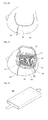
- FIG. 1 shows a brain cooling device for a craniotomy patient installed so that it can come into contact with the brain or the dura mater according to a first embodiment of the present invention.
- the brain cooling device for a craniotomy patient according to the first embodiment of the present invention includes a cooling portion 200, which is buried in such a manner to come into contact with the brain or the dura mater in a state in which a person's scalp 100 and cranium 110 are dissected and opened, and a withdrawal tube 210, which is exposed to the exterior by penetrating the scalp 100 and the cranium 110.
- the cooling portion 200 may be formed of a soft tube with a hollow center, i.e., in the form of a thin film formed of a material such as urethane or silicone.
- the cooling portion 200 is configured to form multiple bent portions in a zigzag form 201, and have a length sufficient to cover the upper portion of the brain. By installing it in this way, the area that comes in contact with the brain can be maximized, thereby more effectively performing the cooling activity.
- the withdrawal tube 210 should be positioned through cranium perforations 111 formed during incision of the cranium 110, the penetration of the withdrawal tube 210 through the scalp 100 may be performed using a Trocar, and it is preferable that the withdrawal tube 210 be fixed around the scalp 100 using needles and threads for surgery.
- the cooling material may be any material that enables a cooling activity by being subjected to heat exchange along with a physiological saline solution and nitrogen gas.
- FIG. 2 shows a schematic diagram of the internal structure of a cooling portion to be applied to the brain cooling device for a craniotomy patient according to the first embodiment of the present invention.
- the cooling portion 200 is formed to be partitioned into an upper flow channel 202 and a lower flow channel 203, the cooling material may be introduced through one flow channel between the upper flow channel 202 and the lower flow channel 203, and at the same time, the cooling material may be discharged through the other flow channel, thereby minimizing the interference between introduction and discharge. As a result, the cooling efficiency can be improved.
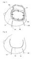
- FIG. 3 shows a state of a fixed cranial bone flap after the completion of installing the brain cooling device for a craniotomy patient according to the first embodiment of the present invention.
- the withdrawal tube 210 may be exposed to the exterior by penetrating through the scalp using a Trocar having a predetermined distance from the sewing portion 102.
- the withdrawal tube 210 may be fixed using needles and threads for surgery near the perforated portion of the scalp. Accordingly, the brain can be maintained at a low temperature by introducing or discharging a cooling material through the withdrawal tube 210.
- FIG. 4 shows a state of a sutured scalp after the completion of installing the brain cooling device for a craniotomy patient according to the first embodiment of the present invention.
- the withdrawal tube 210 may remain exposed to the exterior.
- the brain can be maintained at a low temperature by introducing or discharging a cooling material through the withdrawal tube 210. Later, the entire cooling portion 200 may be easily removed by cutting off the threads fixed to the withdrawal tube 210, and holding the withdrawal tube 210 with a hand and pulling it from the exterior of the scalp.
- FIG. 5 shows a brain cooling device for a craniotomy patient installed so that it can come into contact with the brain or the dura mater according to a second embodiment of the present invention.
- the brain cooling device for a craniotomy patient according to the second embodiment of the present invention has the same constitution as in the first embodiment described above in that the cooling portion 200 is buried in such a manner to come into contact with the brain or the dura mater in a state in which a person's scalp 100 and cranium 110 are dissected and opened.
- the introduction tube 220 and the discharge tube 230 exposed to the exterior by penetrating through the scalp 100 and the cranium 110 are formed.
- FIG. 6 shows a schematic diagram of the internal structure of a cooling portion to be applied to the brain cooling device for a craniotomy patient according to the second embodiment of the present invention.
- a cooling material is introduced through the introduction tube 220 and discharged through the discharge tube 230, and mutual interference between introduction and discharge at the time of introducing and discharging the cooling material can be prevented.
- FIG. 7 shows a state of a sutured cranium after the completion of installing the brain cooling device for a craniotomy patient according to the second embodiment of the present invention.
- the introduction tube 220 and the discharge tube 230 at the two ends that integrally extend from the cooling portion 200 are fixed to the perforations 111 of the cranium 110 and exposed to the exterior.
- FIG. 8 shows a state of a sutured scalp after the completion of installing the brain cooling device for a craniotomy patient according to the first embodiment of the present invention.
- the introduction tube 220 and the discharge tube 230 may be exposed to the exterior by penetrating through the scalp using a Trocar having a predetermined distance from the sewing portion 102.
- the introduction tube 220 and the discharge tube 230 are preferably fixed using needles and threads for surgery near the perforated portions of the scalp.
- the cooling material may move at a faster flow rate, thereby further improving cooling performance.
- the entire cooling portion 200 may be easily removed by cutting off any one of the threads fixed to introduction tube 220 and the discharge tube 230, and holding the other tube with a hand and pulling it from the exterior of the scalp.
- the brain cooling device of the present invention when applied during the implementation of therapeutic hypothermia to alleviate cerebral edema, increased intracranial pressure, etc., in the case of various types of brain damage such as a cerebral infarction, a cerebral hemorrhage, head trauma, etc., helps to effectively lower brain temperature, and a cooling portion can be easily removed in a bed.
- the brain cooling device of the present invention may be used in the field of medical devices for improving the efficiency of the therapeutic hypothermia.
Landscapes
- Health & Medical Sciences (AREA)
- Life Sciences & Earth Sciences (AREA)
- Animal Behavior & Ethology (AREA)
- General Health & Medical Sciences (AREA)
- Biomedical Technology (AREA)
- Heart & Thoracic Surgery (AREA)
- Engineering & Computer Science (AREA)
- Veterinary Medicine (AREA)
- Public Health (AREA)
- Vascular Medicine (AREA)
- Physics & Mathematics (AREA)
- Thermal Sciences (AREA)
- Surgery (AREA)
- Nuclear Medicine, Radiotherapy & Molecular Imaging (AREA)
- Otolaryngology (AREA)
- Medical Informatics (AREA)
- Molecular Biology (AREA)
- Thermotherapy And Cooling Therapy Devices (AREA)
Abstract
Description
- This application claims priority to and the benefit of Korean Patent Application No.
10-2012-0015558, filed on February 15, 2012 - The present invention relates to a brain cooling device for a craniotomy patient, and more particularly, to a brain cooling device for a craniotomy patient that cools the brain serving as a region for surgery to prevent edema and damage to the patient's brain immediately after the craniotomy.
- In general, in the case of various types of brain damage such as a cerebral infarction, a cerebral hemorrhage, head trauma, etc., the implementation of therapeutic hypothermia to drop brain temperature may help to alleviate cerebral edema, increased intracranial pressure, and the like due to a disease.
- Here, to drop the brain temperature, the brain temperature may drop due to the decreased temperature of the whole body, however, effectively lowering the brain temperature by directly lowering the brain temperature is impossible because the brain is encompassed by the cranium and the scalp.
- The present invention, with an object to resolve the above-described problems, is directed to installing a brain cooling device through a region for surgery at the time of craniotomy, lowering the brain temperature during the period required after the surgery, and easily removing the brain cooling device inserted into the skull in a bed without further surgery once the therapeutic period has ended.
- According to an aspect of the present invention, there is provided a brain cooling device for a craniotomy patient, comprising: a cooling portion which is buried in such a manner to come into contact with the brain or the dura mater; and one withdrawal tube, which is one end of the cooling portion exposed to the exterior, wherein the withdrawal tube is exposed to the exterior by penetrating through the scalp and the cranium.
- According to another aspect of the present invention, there is provided a cooling portion which is buried in such a manner to come into contact with the brain or the dura mater; and an introduction tube and a discharge tube, which are two end portions of the cooling portion exposed to the exterior, wherein the introduction tube and the discharge tube are exposed to the exterior by penetrating through the scalp and the cranium.
- According to another aspect of the present invention, the cooling portion may include soft tubes with a predetermined length.
- According to another aspect of the present invention, the cooling portion may be configured to cover the upper part of the brain by forming multiple bent portions in a zigzag form.
- According to another aspect of the present invention, a cooling material may be introduced or discharged through the withdrawal tube.
- According to another aspect of the present invention, a cooling material may be introduced through the introduction tube and discharged through the withdrawal tube.
- As described above, according to the brain cooling device for a craniotomy patient of the present invention, the cooling of brain can be effectively performed by installing a cooling portion that comes into direct contact with the brain or the dura mater, and using a cooling material which flows inside the cooling portion, and also the cooling portion can be easily removed in a bed.
-
-
FIG. 1 shows a brain cooling device for a craniotomy patient installed so that it can come into contact with the brain or the dura mater according to a first embodiment of the present invention; -
FIG. 2 shows a schematic diagram of the internal structure of a cooling portion to be applied to the brain cooling device for a craniotomy patient according to the first embodiment of the present invention; -
FIG. 3 shows a state of a fixed cranial bone flap after the completion of installing the brain cooling device for a craniotomy patient according to the first embodiment of the present invention; -
FIG. 4 shows a state of a sutured scalp after the completion of installing the brain cooling device for a craniotomy patient according to the first embodiment of the present invention; -
FIG. 5 shows a brain cooling device for a craniotomy patient installed so that it can come into contact with the brain or the dura mater according to a second embodiment of the present invention; -
FIG. 6 shows a schematic diagram of the internal structure of a cooling portion to be applied to the brain cooling device for a craniotomy patient according to the second embodiment of the present invention; -
FIG. 7 shows a state of a fixed cranial bone flap after the completion of installing the brain cooling device for a craniotomy patient according to the second embodiment of the present invention; and -
FIG. 8 shows a state of a sutured scalp after the completion of installing the brain cooling device for a craniotomy patient according to the first embodiment of the present invention. - Exemplary embodiments of the present invention will be described in detail below with reference to the accompanying drawings.
-
FIG. 1 shows a brain cooling device for a craniotomy patient installed so that it can come into contact with the brain or the dura mater according to a first embodiment of the present invention. As shown inFIG. 1 , the brain cooling device for a craniotomy patient according to the first embodiment of the present invention includes acooling portion 200, which is buried in such a manner to come into contact with the brain or the dura mater in a state in which a person'sscalp 100 andcranium 110 are dissected and opened, and awithdrawal tube 210, which is exposed to the exterior by penetrating thescalp 100 and thecranium 110. In particular, thecooling portion 200 may be formed of a soft tube with a hollow center, i.e., in the form of a thin film formed of a material such as urethane or silicone. - Additionally, the
cooling portion 200 is configured to form multiple bent portions in azigzag form 201, and have a length sufficient to cover the upper portion of the brain. By installing it in this way, the area that comes in contact with the brain can be maximized, thereby more effectively performing the cooling activity. - Furthermore, the
withdrawal tube 210 should be positioned throughcranium perforations 111 formed during incision of thecranium 110, the penetration of thewithdrawal tube 210 through thescalp 100 may be performed using a Trocar, and it is preferable that thewithdrawal tube 210 be fixed around thescalp 100 using needles and threads for surgery. - Then, a cooling material is introduced and discharged through the
withdrawal tube 210. Of course, the cooling material may be any material that enables a cooling activity by being subjected to heat exchange along with a physiological saline solution and nitrogen gas. - In addition,
FIG. 2 shows a schematic diagram of the internal structure of a cooling portion to be applied to the brain cooling device for a craniotomy patient according to the first embodiment of the present invention. As shown inFIG. 2 , if thecooling portion 200 is formed to be partitioned into anupper flow channel 202 and alower flow channel 203, the cooling material may be introduced through one flow channel between theupper flow channel 202 and thelower flow channel 203, and at the same time, the cooling material may be discharged through the other flow channel, thereby minimizing the interference between introduction and discharge. As a result, the cooling efficiency can be improved. -
FIG. 3 shows a state of a fixed cranial bone flap after the completion of installing the brain cooling device for a craniotomy patient according to the first embodiment of the present invention. As shown inFIG. 3 , thewithdrawal tube 210 may be exposed to the exterior by penetrating through the scalp using a Trocar having a predetermined distance from thesewing portion 102. In particular, thewithdrawal tube 210 may be fixed using needles and threads for surgery near the perforated portion of the scalp. Accordingly, the brain can be maintained at a low temperature by introducing or discharging a cooling material through thewithdrawal tube 210. -
FIG. 4 shows a state of a sutured scalp after the completion of installing the brain cooling device for a craniotomy patient according to the first embodiment of the present invention. As shown inFIG. 4 , when thescalp 100 is completely sealed by thesewing portion 102, thewithdrawal tube 210 may remain exposed to the exterior. As such, the brain can be maintained at a low temperature by introducing or discharging a cooling material through thewithdrawal tube 210. Later, theentire cooling portion 200 may be easily removed by cutting off the threads fixed to thewithdrawal tube 210, and holding thewithdrawal tube 210 with a hand and pulling it from the exterior of the scalp. -
FIG. 5 shows a brain cooling device for a craniotomy patient installed so that it can come into contact with the brain or the dura mater according to a second embodiment of the present invention. As shown inFIG. 5 , the brain cooling device for a craniotomy patient according to the second embodiment of the present invention has the same constitution as in the first embodiment described above in that thecooling portion 200 is buried in such a manner to come into contact with the brain or the dura mater in a state in which a person'sscalp 100 andcranium 110 are dissected and opened. However, in the two end portions formed as an integral body extending from thecooling portion 200, theintroduction tube 220 and thedischarge tube 230 exposed to the exterior by penetrating through thescalp 100 and thecranium 110 are formed. - In particular,
FIG. 6 shows a schematic diagram of the internal structure of a cooling portion to be applied to the brain cooling device for a craniotomy patient according to the second embodiment of the present invention. As shown inFIG. 6 , although respective flow channels are formed inside theintroduction tube 220 and thedischarge tube 230, a cooling material is introduced through theintroduction tube 220 and discharged through thedischarge tube 230, and mutual interference between introduction and discharge at the time of introducing and discharging the cooling material can be prevented. -
FIG. 7 shows a state of a sutured cranium after the completion of installing the brain cooling device for a craniotomy patient according to the second embodiment of the present invention. As shown inFIG. 7 , if an already-open cranium 110 is closed and sealed tightly using an additionally providedbinding member 300, theintroduction tube 220 and thedischarge tube 230 at the two ends that integrally extend from thecooling portion 200 are fixed to theperforations 111 of thecranium 110 and exposed to the exterior. -
FIG. 8 shows a state of a sutured scalp after the completion of installing the brain cooling device for a craniotomy patient according to the first embodiment of the present invention. As shown inFIG. 8 , theintroduction tube 220 and thedischarge tube 230 may be exposed to the exterior by penetrating through the scalp using a Trocar having a predetermined distance from thesewing portion 102. In particular, theintroduction tube 220 and thedischarge tube 230 are preferably fixed using needles and threads for surgery near the perforated portions of the scalp. By discharging a cooling material through thedischarge tube 230 while simultaneously introducing the cooling material through theintroduction tube 220, the cooling material may move at a faster flow rate, thereby further improving cooling performance. Later, theentire cooling portion 200 may be easily removed by cutting off any one of the threads fixed tointroduction tube 220 and thedischarge tube 230, and holding the other tube with a hand and pulling it from the exterior of the scalp. - It will be apparent to those skilled in the art that various modifications can be made to the above-described exemplary embodiments of the present invention without departing from the spirit or scope of the invention. Thus, it is intended that the present invention covers all such modifications provided they come within the scope of the appended claims and their equivalents.
- The brain cooling device of the present invention, when applied during the implementation of therapeutic hypothermia to alleviate cerebral edema, increased intracranial pressure, etc., in the case of various types of brain damage such as a cerebral infarction, a cerebral hemorrhage, head trauma, etc., helps to effectively lower brain temperature, and a cooling portion can be easily removed in a bed. The brain cooling device of the present invention may be used in the field of medical devices for improving the efficiency of the therapeutic hypothermia.
Claims (6)
- A brain cooling device for a craniotomy patient, comprising:a cooling portion which is buried in such a manner to come into contact with the brain or the dura mater; andone withdrawal tube, which is one end of the cooling portion that is exposed to the exterior, wherein the withdrawal tube is exposed to the exterior by penetrating through the scalp and the cranium.
- A brain cooling device for a craniotomy patient, comprising:a cooling portion which is buried in such a manner to come into contact with the brain or the dura mater; andan introduction tube and a discharge tube, which are two end portions of the cooling portion that are exposed to the exterior, wherein the introduction tube and the discharge tube are exposed to the exterior by penetrating through the scalp and the cranium.
- The brain cooling device according to claim 1 or claim 2, wherein the cooling portion comprises a soft tube with a predetermined length.
- The brain cooling device according to claim 3, wherein the cooling portion is configured to cover the upper part of the brain by forming multiple bent portions in a zigzag form.
- The brain cooling device according to claim 1, wherein a cooling material is introduced or discharged through the withdrawal tube.
- The brain cooling device according to claim 2, wherein a cooling material is discharged through the withdrawal tube simultaneously as the cooling material is introduced through the introduction tube.
Applications Claiming Priority (2)
| Application Number | Priority Date | Filing Date | Title |
|---|---|---|---|
| KR1020120015558A KR101361344B1 (en) | 2012-02-15 | 2012-02-15 | Brain cooling device for craniotomy patient |
| PCT/KR2013/000959 WO2013122351A1 (en) | 2012-02-15 | 2013-02-06 | Brain cooling device for open-skull surgery patient |
Publications (3)
| Publication Number | Publication Date |
|---|---|
| EP2815712A1 true EP2815712A1 (en) | 2014-12-24 |
| EP2815712A4 EP2815712A4 (en) | 2015-10-07 |
| EP2815712B1 EP2815712B1 (en) | 2019-06-19 |
Family
ID=48984429
Family Applications (1)
| Application Number | Title | Priority Date | Filing Date |
|---|---|---|---|
| EP13749314.4A Active EP2815712B1 (en) | 2012-02-15 | 2013-02-06 | Brain cooling device for open-skull surgery patient |
Country Status (5)
| Country | Link |
|---|---|
| US (1) | US20150045858A1 (en) |
| EP (1) | EP2815712B1 (en) |
| KR (1) | KR101361344B1 (en) |
| ES (1) | ES2739378T3 (en) |
| WO (1) | WO2013122351A1 (en) |
Family Cites Families (10)
| Publication number | Priority date | Publication date | Assignee | Title |
|---|---|---|---|---|
| US6106518A (en) * | 1998-04-09 | 2000-08-22 | Cryocath Technologies, Inc. | Variable geometry tip for a cryosurgical ablation device |
| CA2404430A1 (en) | 2000-04-07 | 2001-10-18 | Albert S. Lee | Methods and apparatus for thermally affecting tissue |
| US6660026B2 (en) * | 2000-10-05 | 2003-12-09 | Seacoast Technologies, Inc. | Multi-tipped cooling probe |
| US6699269B2 (en) * | 2001-04-30 | 2004-03-02 | Rohit K. Khanna | Selective brain and spinal cord hypothermia method and apparatus |
| AU2003241673A1 (en) * | 2002-06-17 | 2003-12-31 | Atsuo Mori | Catheter for topical cooling and topical cooling device using the same |
| US6733442B1 (en) * | 2002-10-21 | 2004-05-11 | Seacoast Technologies, Inc. | Accessory for surgical instrument |
| US20050246000A1 (en) * | 2004-05-03 | 2005-11-03 | Seacoast Technologies, Inc. | Cooled craniectomy |
| JP2007209523A (en) | 2006-02-09 | 2007-08-23 | Yamaguchi Univ | Intracranial implantable cerebral cooling device |
| WO2009004635A2 (en) | 2007-07-04 | 2009-01-08 | Eliahu Arad | System and method for manipulating a temperature of a patient |
| JP2011083315A (en) | 2009-10-13 | 2011-04-28 | Yamaguchi Univ | Local cooling system |
-
2012
- 2012-02-15 KR KR1020120015558A patent/KR101361344B1/en active Active
-
2013
- 2013-02-06 ES ES13749314T patent/ES2739378T3/en active Active
- 2013-02-06 WO PCT/KR2013/000959 patent/WO2013122351A1/en not_active Ceased
- 2013-02-06 US US14/375,276 patent/US20150045858A1/en not_active Abandoned
- 2013-02-06 EP EP13749314.4A patent/EP2815712B1/en active Active
Also Published As
| Publication number | Publication date |
|---|---|
| WO2013122351A1 (en) | 2013-08-22 |
| US20150045858A1 (en) | 2015-02-12 |
| ES2739378T3 (en) | 2020-01-30 |
| KR20130094140A (en) | 2013-08-23 |
| KR101361344B1 (en) | 2014-02-12 |
| EP2815712A4 (en) | 2015-10-07 |
| EP2815712B1 (en) | 2019-06-19 |
Similar Documents
| Publication | Publication Date | Title |
|---|---|---|
| ES2245692T3 (en) | STAPLE FOR CRANIAL COVER. | |
| Lobe et al. | Novel uses of surgical robotics in head and neck surgery | |
| US7455666B2 (en) | Methods and apparatuses for navigating the subarachnoid space | |
| EP3222219B1 (en) | Laparoscopic port site closing apparatus | |
| JP5140812B2 (en) | Intervertebral implant | |
| Hernesniemi et al. | Subtemporal approach to basilar bifurcation aneurysms: advanced technique and clinical experience | |
| WO2007069232A3 (en) | Improved radial expansible retractor for minimally invasive surgery | |
| CN105307564A (en) | Cerebrospinal fluid cooling device | |
| CN106466195A (en) | Retractor for surgical operation | |
| EP2713904A1 (en) | Aneurysm devices with additional anchoring mechanisms and associated systems and methods | |
| EP2815711A1 (en) | Brain cooling device also having fluid discharge function | |
| EP2815712B1 (en) | Brain cooling device for open-skull surgery patient | |
| CN106512185A (en) | Craniocerebral drainage tube | |
| EP3103377A1 (en) | Endoscope with continuous luminal perfusion and reflux functions | |
| JP4196248B2 (en) | Fixture to fix the skull flap to the skull | |
| Passeri et al. | A new simple and free tubular device for microscopic transcortical approach to deep-seated lesions: technical note and case example | |
| BRPI1105137B1 (en) | multi-function plaque for cranial neurological surgery | |
| KR20140110457A (en) | Pad for brain cooling device | |
| Aboghazleh et al. | Craniotomy for acute monitoring of pial vessels in the rodent brain | |
| Maruyama et al. | One-stage clipping of bilateral middle cerebral artery aneurysms via the bilateral pterional keyhole approach | |
| US11324536B2 (en) | Seal for laparoscopic access port | |
| RU96762U1 (en) | DEVICE FOR COOLING THE EXTERNAL COVER OF THE HUMAN HEAD AND BRAIN | |
| Dumont et al. | Surgical management of unruptured basilar artery bifurcation aneurysms | |
| Wong et al. | Supraorbital and transorbital minicraniotomies | |
| KR102102531B1 (en) | Laparoscopioc trocar |
Legal Events
| Date | Code | Title | Description |
|---|---|---|---|
| PUAI | Public reference made under article 153(3) epc to a published international application that has entered the european phase |
Free format text: ORIGINAL CODE: 0009012 |
|
| 17P | Request for examination filed |
Effective date: 20140905 |
|
| AK | Designated contracting states |
Kind code of ref document: A1 Designated state(s): AL AT BE BG CH CY CZ DE DK EE ES FI FR GB GR HR HU IE IS IT LI LT LU LV MC MK MT NL NO PL PT RO RS SE SI SK SM TR |
|
| AX | Request for extension of the european patent |
Extension state: BA ME |
|
| DAX | Request for extension of the european patent (deleted) | ||
| RIN1 | Information on inventor provided before grant (corrected) |
Inventor name: RHEE, DONG ICK Inventor name: PARK, JAE CHAN Inventor name: SUK, KYOUNG HO Inventor name: HAN, HYUNG SOO |
|
| RA4 | Supplementary search report drawn up and despatched (corrected) |
Effective date: 20150907 |
|
| RIC1 | Information provided on ipc code assigned before grant |
Ipc: A61F 7/12 20060101AFI20150901BHEP |
|
| STAA | Information on the status of an ep patent application or granted ep patent |
Free format text: STATUS: EXAMINATION IS IN PROGRESS |
|
| 17Q | First examination report despatched |
Effective date: 20180416 |
|
| GRAP | Despatch of communication of intention to grant a patent |
Free format text: ORIGINAL CODE: EPIDOSNIGR1 |
|
| STAA | Information on the status of an ep patent application or granted ep patent |
Free format text: STATUS: GRANT OF PATENT IS INTENDED |
|
| INTG | Intention to grant announced |
Effective date: 20190102 |
|
| GRAS | Grant fee paid |
Free format text: ORIGINAL CODE: EPIDOSNIGR3 |
|
| GRAA | (expected) grant |
Free format text: ORIGINAL CODE: 0009210 |
|
| STAA | Information on the status of an ep patent application or granted ep patent |
Free format text: STATUS: THE PATENT HAS BEEN GRANTED |
|
| AK | Designated contracting states |
Kind code of ref document: B1 Designated state(s): AL AT BE BG CH CY CZ DE DK EE ES FI FR GB GR HR HU IE IS IT LI LT LU LV MC MK MT NL NO PL PT RO RS SE SI SK SM TR |
|
| REG | Reference to a national code |
Ref country code: GB Ref legal event code: FG4D |
|
| REG | Reference to a national code |
Ref country code: CH Ref legal event code: EP |
|
| REG | Reference to a national code |
Ref country code: IE Ref legal event code: FG4D |
|
| REG | Reference to a national code |
Ref country code: DE Ref legal event code: R096 Ref document number: 602013056802 Country of ref document: DE |
|
| REG | Reference to a national code |
Ref country code: AT Ref legal event code: REF Ref document number: 1144546 Country of ref document: AT Kind code of ref document: T Effective date: 20190715 |
|
| REG | Reference to a national code |
Ref country code: NL Ref legal event code: MP Effective date: 20190619 |
|
| PG25 | Lapsed in a contracting state [announced via postgrant information from national office to epo] |
Ref country code: SE Free format text: LAPSE BECAUSE OF FAILURE TO SUBMIT A TRANSLATION OF THE DESCRIPTION OR TO PAY THE FEE WITHIN THE PRESCRIBED TIME-LIMIT Effective date: 20190619 Ref country code: HR Free format text: LAPSE BECAUSE OF FAILURE TO SUBMIT A TRANSLATION OF THE DESCRIPTION OR TO PAY THE FEE WITHIN THE PRESCRIBED TIME-LIMIT Effective date: 20190619 Ref country code: LT Free format text: LAPSE BECAUSE OF FAILURE TO SUBMIT A TRANSLATION OF THE DESCRIPTION OR TO PAY THE FEE WITHIN THE PRESCRIBED TIME-LIMIT Effective date: 20190619 Ref country code: AL Free format text: LAPSE BECAUSE OF FAILURE TO SUBMIT A TRANSLATION OF THE DESCRIPTION OR TO PAY THE FEE WITHIN THE PRESCRIBED TIME-LIMIT Effective date: 20190619 Ref country code: NO Free format text: LAPSE BECAUSE OF FAILURE TO SUBMIT A TRANSLATION OF THE DESCRIPTION OR TO PAY THE FEE WITHIN THE PRESCRIBED TIME-LIMIT Effective date: 20190919 Ref country code: FI Free format text: LAPSE BECAUSE OF FAILURE TO SUBMIT A TRANSLATION OF THE DESCRIPTION OR TO PAY THE FEE WITHIN THE PRESCRIBED TIME-LIMIT Effective date: 20190619 |
|
| REG | Reference to a national code |
Ref country code: LT Ref legal event code: MG4D |
|
| PG25 | Lapsed in a contracting state [announced via postgrant information from national office to epo] |
Ref country code: BG Free format text: LAPSE BECAUSE OF FAILURE TO SUBMIT A TRANSLATION OF THE DESCRIPTION OR TO PAY THE FEE WITHIN THE PRESCRIBED TIME-LIMIT Effective date: 20190919 Ref country code: LV Free format text: LAPSE BECAUSE OF FAILURE TO SUBMIT A TRANSLATION OF THE DESCRIPTION OR TO PAY THE FEE WITHIN THE PRESCRIBED TIME-LIMIT Effective date: 20190619 Ref country code: RS Free format text: LAPSE BECAUSE OF FAILURE TO SUBMIT A TRANSLATION OF THE DESCRIPTION OR TO PAY THE FEE WITHIN THE PRESCRIBED TIME-LIMIT Effective date: 20190619 Ref country code: GR Free format text: LAPSE BECAUSE OF FAILURE TO SUBMIT A TRANSLATION OF THE DESCRIPTION OR TO PAY THE FEE WITHIN THE PRESCRIBED TIME-LIMIT Effective date: 20190920 |
|
| REG | Reference to a national code |
Ref country code: AT Ref legal event code: MK05 Ref document number: 1144546 Country of ref document: AT Kind code of ref document: T Effective date: 20190619 |
|
| REG | Reference to a national code |
Ref country code: ES Ref legal event code: FG2A Ref document number: 2739378 Country of ref document: ES Kind code of ref document: T3 Effective date: 20200130 |
|
| PG25 | Lapsed in a contracting state [announced via postgrant information from national office to epo] |
Ref country code: EE Free format text: LAPSE BECAUSE OF FAILURE TO SUBMIT A TRANSLATION OF THE DESCRIPTION OR TO PAY THE FEE WITHIN THE PRESCRIBED TIME-LIMIT Effective date: 20190619 Ref country code: NL Free format text: LAPSE BECAUSE OF FAILURE TO SUBMIT A TRANSLATION OF THE DESCRIPTION OR TO PAY THE FEE WITHIN THE PRESCRIBED TIME-LIMIT Effective date: 20190619 Ref country code: SK Free format text: LAPSE BECAUSE OF FAILURE TO SUBMIT A TRANSLATION OF THE DESCRIPTION OR TO PAY THE FEE WITHIN THE PRESCRIBED TIME-LIMIT Effective date: 20190619 Ref country code: CZ Free format text: LAPSE BECAUSE OF FAILURE TO SUBMIT A TRANSLATION OF THE DESCRIPTION OR TO PAY THE FEE WITHIN THE PRESCRIBED TIME-LIMIT Effective date: 20190619 Ref country code: RO Free format text: LAPSE BECAUSE OF FAILURE TO SUBMIT A TRANSLATION OF THE DESCRIPTION OR TO PAY THE FEE WITHIN THE PRESCRIBED TIME-LIMIT Effective date: 20190619 Ref country code: AT Free format text: LAPSE BECAUSE OF FAILURE TO SUBMIT A TRANSLATION OF THE DESCRIPTION OR TO PAY THE FEE WITHIN THE PRESCRIBED TIME-LIMIT Effective date: 20190619 Ref country code: PT Free format text: LAPSE BECAUSE OF FAILURE TO SUBMIT A TRANSLATION OF THE DESCRIPTION OR TO PAY THE FEE WITHIN THE PRESCRIBED TIME-LIMIT Effective date: 20191021 |
|
| PG25 | Lapsed in a contracting state [announced via postgrant information from national office to epo] |
Ref country code: IS Free format text: LAPSE BECAUSE OF FAILURE TO SUBMIT A TRANSLATION OF THE DESCRIPTION OR TO PAY THE FEE WITHIN THE PRESCRIBED TIME-LIMIT Effective date: 20191019 Ref country code: SM Free format text: LAPSE BECAUSE OF FAILURE TO SUBMIT A TRANSLATION OF THE DESCRIPTION OR TO PAY THE FEE WITHIN THE PRESCRIBED TIME-LIMIT Effective date: 20190619 Ref country code: IT Free format text: LAPSE BECAUSE OF FAILURE TO SUBMIT A TRANSLATION OF THE DESCRIPTION OR TO PAY THE FEE WITHIN THE PRESCRIBED TIME-LIMIT Effective date: 20190619 |
|
| PG25 | Lapsed in a contracting state [announced via postgrant information from national office to epo] |
Ref country code: TR Free format text: LAPSE BECAUSE OF FAILURE TO SUBMIT A TRANSLATION OF THE DESCRIPTION OR TO PAY THE FEE WITHIN THE PRESCRIBED TIME-LIMIT Effective date: 20190619 |
|
| PG25 | Lapsed in a contracting state [announced via postgrant information from national office to epo] |
Ref country code: DK Free format text: LAPSE BECAUSE OF FAILURE TO SUBMIT A TRANSLATION OF THE DESCRIPTION OR TO PAY THE FEE WITHIN THE PRESCRIBED TIME-LIMIT Effective date: 20190619 Ref country code: PL Free format text: LAPSE BECAUSE OF FAILURE TO SUBMIT A TRANSLATION OF THE DESCRIPTION OR TO PAY THE FEE WITHIN THE PRESCRIBED TIME-LIMIT Effective date: 20190619 |
|
| PG25 | Lapsed in a contracting state [announced via postgrant information from national office to epo] |
Ref country code: IS Free format text: LAPSE BECAUSE OF FAILURE TO SUBMIT A TRANSLATION OF THE DESCRIPTION OR TO PAY THE FEE WITHIN THE PRESCRIBED TIME-LIMIT Effective date: 20200224 |
|
| REG | Reference to a national code |
Ref country code: DE Ref legal event code: R097 Ref document number: 602013056802 Country of ref document: DE |
|
| PLBE | No opposition filed within time limit |
Free format text: ORIGINAL CODE: 0009261 |
|
| STAA | Information on the status of an ep patent application or granted ep patent |
Free format text: STATUS: NO OPPOSITION FILED WITHIN TIME LIMIT |
|
| PG2D | Information on lapse in contracting state deleted |
Ref country code: IS |
|
| 26N | No opposition filed |
Effective date: 20200603 |
|
| PG25 | Lapsed in a contracting state [announced via postgrant information from national office to epo] |
Ref country code: SI Free format text: LAPSE BECAUSE OF FAILURE TO SUBMIT A TRANSLATION OF THE DESCRIPTION OR TO PAY THE FEE WITHIN THE PRESCRIBED TIME-LIMIT Effective date: 20190619 |
|
| REG | Reference to a national code |
Ref country code: CH Ref legal event code: PL |
|
| GBPC | Gb: european patent ceased through non-payment of renewal fee |
Effective date: 20200206 |
|
| REG | Reference to a national code |
Ref country code: BE Ref legal event code: MM Effective date: 20200229 |
|
| PG25 | Lapsed in a contracting state [announced via postgrant information from national office to epo] |
Ref country code: MC Free format text: LAPSE BECAUSE OF FAILURE TO SUBMIT A TRANSLATION OF THE DESCRIPTION OR TO PAY THE FEE WITHIN THE PRESCRIBED TIME-LIMIT Effective date: 20190619 Ref country code: LU Free format text: LAPSE BECAUSE OF NON-PAYMENT OF DUE FEES Effective date: 20200206 |
|
| PG25 | Lapsed in a contracting state [announced via postgrant information from national office to epo] |
Ref country code: LI Free format text: LAPSE BECAUSE OF NON-PAYMENT OF DUE FEES Effective date: 20200229 Ref country code: CH Free format text: LAPSE BECAUSE OF NON-PAYMENT OF DUE FEES Effective date: 20200229 |
|
| PG25 | Lapsed in a contracting state [announced via postgrant information from national office to epo] |
Ref country code: GB Free format text: LAPSE BECAUSE OF NON-PAYMENT OF DUE FEES Effective date: 20200206 Ref country code: IE Free format text: LAPSE BECAUSE OF NON-PAYMENT OF DUE FEES Effective date: 20200206 |
|
| PG25 | Lapsed in a contracting state [announced via postgrant information from national office to epo] |
Ref country code: BE Free format text: LAPSE BECAUSE OF NON-PAYMENT OF DUE FEES Effective date: 20200229 |
|
| PG25 | Lapsed in a contracting state [announced via postgrant information from national office to epo] |
Ref country code: MT Free format text: LAPSE BECAUSE OF FAILURE TO SUBMIT A TRANSLATION OF THE DESCRIPTION OR TO PAY THE FEE WITHIN THE PRESCRIBED TIME-LIMIT Effective date: 20190619 Ref country code: CY Free format text: LAPSE BECAUSE OF FAILURE TO SUBMIT A TRANSLATION OF THE DESCRIPTION OR TO PAY THE FEE WITHIN THE PRESCRIBED TIME-LIMIT Effective date: 20190619 |
|
| PG25 | Lapsed in a contracting state [announced via postgrant information from national office to epo] |
Ref country code: MK Free format text: LAPSE BECAUSE OF FAILURE TO SUBMIT A TRANSLATION OF THE DESCRIPTION OR TO PAY THE FEE WITHIN THE PRESCRIBED TIME-LIMIT Effective date: 20190619 |
|
| PGFP | Annual fee paid to national office [announced via postgrant information from national office to epo] |
Ref country code: ES Payment date: 20260310 Year of fee payment: 14 |
|
| PGFP | Annual fee paid to national office [announced via postgrant information from national office to epo] |
Ref country code: DE Payment date: 20260107 Year of fee payment: 14 |
|
| PGFP | Annual fee paid to national office [announced via postgrant information from national office to epo] |
Ref country code: FR Payment date: 20260108 Year of fee payment: 14 |