EP2815502B1 - Improved capture buffer of digital predistortion systems - Google Patents
Improved capture buffer of digital predistortion systems Download PDFInfo
- Publication number
- EP2815502B1 EP2815502B1 EP11771575.5A EP11771575A EP2815502B1 EP 2815502 B1 EP2815502 B1 EP 2815502B1 EP 11771575 A EP11771575 A EP 11771575A EP 2815502 B1 EP2815502 B1 EP 2815502B1
- Authority
- EP
- European Patent Office
- Prior art keywords
- power
- signal
- value
- data
- capture
- Prior art date
- Legal status (The legal status is an assumption and is not a legal conclusion. Google has not performed a legal analysis and makes no representation as to the accuracy of the status listed.)
- Not-in-force
Links
- 230000005540 biological transmission Effects 0.000 claims description 104
- 230000006870 function Effects 0.000 claims description 100
- 230000008859 change Effects 0.000 claims description 27
- 238000013481 data capture Methods 0.000 claims description 26
- 238000000034 method Methods 0.000 claims description 19
- 238000005259 measurement Methods 0.000 claims description 17
- 230000008569 process Effects 0.000 claims description 8
- 230000004044 response Effects 0.000 claims description 6
- 238000012935 Averaging Methods 0.000 claims description 4
- 230000000977 initiatory effect Effects 0.000 claims description 3
- 238000012544 monitoring process Methods 0.000 claims 2
- 230000001052 transient effect Effects 0.000 description 6
- 238000004891 communication Methods 0.000 description 3
- 230000009286 beneficial effect Effects 0.000 description 2
- 238000006243 chemical reaction Methods 0.000 description 2
- 230000000694 effects Effects 0.000 description 2
- 238000013507 mapping Methods 0.000 description 2
- 230000007246 mechanism Effects 0.000 description 2
- 230000000717 retained effect Effects 0.000 description 2
- 238000005070 sampling Methods 0.000 description 2
- 230000007704 transition Effects 0.000 description 2
- 238000013459 approach Methods 0.000 description 1
- 230000006399 behavior Effects 0.000 description 1
- 230000008901 benefit Effects 0.000 description 1
- 230000003247 decreasing effect Effects 0.000 description 1
- 230000001934 delay Effects 0.000 description 1
- 230000007774 longterm Effects 0.000 description 1
- 238000012986 modification Methods 0.000 description 1
- 230000004048 modification Effects 0.000 description 1
- 230000009022 nonlinear effect Effects 0.000 description 1
- 230000000737 periodic effect Effects 0.000 description 1
- 238000012545 processing Methods 0.000 description 1
Images


Classifications
-
- H—ELECTRICITY
- H03—ELECTRONIC CIRCUITRY
- H03F—AMPLIFIERS
- H03F1/00—Details of amplifiers with only discharge tubes, only semiconductor devices or only unspecified devices as amplifying elements
- H03F1/32—Modifications of amplifiers to reduce non-linear distortion
- H03F1/3241—Modifications of amplifiers to reduce non-linear distortion using predistortion circuits
- H03F1/3247—Modifications of amplifiers to reduce non-linear distortion using predistortion circuits using feedback acting on predistortion circuits
-
- H—ELECTRICITY
- H03—ELECTRONIC CIRCUITRY
- H03F—AMPLIFIERS
- H03F3/00—Amplifiers with only discharge tubes or only semiconductor devices as amplifying elements
- H03F3/189—High-frequency amplifiers, e.g. radio frequency amplifiers
- H03F3/19—High-frequency amplifiers, e.g. radio frequency amplifiers with semiconductor devices only
- H03F3/195—High-frequency amplifiers, e.g. radio frequency amplifiers with semiconductor devices only in integrated circuits
-
- H—ELECTRICITY
- H03—ELECTRONIC CIRCUITRY
- H03F—AMPLIFIERS
- H03F3/00—Amplifiers with only discharge tubes or only semiconductor devices as amplifying elements
- H03F3/20—Power amplifiers, e.g. Class B amplifiers, Class C amplifiers
- H03F3/24—Power amplifiers, e.g. Class B amplifiers, Class C amplifiers of transmitter output stages
-
- H—ELECTRICITY
- H04—ELECTRIC COMMUNICATION TECHNIQUE
- H04L—TRANSMISSION OF DIGITAL INFORMATION, e.g. TELEGRAPHIC COMMUNICATION
- H04L27/00—Modulated-carrier systems
- H04L27/32—Carrier systems characterised by combinations of two or more of the types covered by groups H04L27/02, H04L27/10, H04L27/18 or H04L27/26
- H04L27/34—Amplitude- and phase-modulated carrier systems, e.g. quadrature-amplitude modulated carrier systems
- H04L27/36—Modulator circuits; Transmitter circuits
- H04L27/366—Arrangements for compensating undesirable properties of the transmission path between the modulator and the demodulator
- H04L27/367—Arrangements for compensating undesirable properties of the transmission path between the modulator and the demodulator using predistortion
-
- H—ELECTRICITY
- H03—ELECTRONIC CIRCUITRY
- H03F—AMPLIFIERS
- H03F2201/00—Indexing scheme relating to details of amplifiers with only discharge tubes, only semiconductor devices or only unspecified devices as amplifying elements covered by H03F1/00
- H03F2201/32—Indexing scheme relating to modifications of amplifiers to reduce non-linear distortion
- H03F2201/3227—Adaptive predistortion based on amplitude, envelope or power level feedback from the output of the main amplifier
Definitions
- DPD digital predistortion
- CB improved capture buffer
- DPD systems are often employed in communications system transmitters to allow a power amplifier to be driven into its non-linear region.
- a baseband signal is processed by a predistorter.
- the predistorter is a nonlinear device which creates a signal that is forwarded to the nonlinear power amplifier, such that the cascade of the nonlinear predistorter and the nonlinear power amplifier produces a system that is linear overall.
- the signal being sent from the nonlinear device to an antenna is simply a scaled up version of the signal that arrived from the baseband.
- the baseband signal comes in and is sent through a total of N pdf predistortion functions.
- Power amplifiers typically have different characteristics at different transmission power levels. Hence, different predistortion functions are typically needed to correct power amplifier performance at different transmission power levels.
- the number of predistortion functions depends on the power amplifier being used because different power amplifiers require a different number of predistortion functions.
- Each predistortion function is responsible for linearizing a power amplifier when the power amplifier is transmitting inside a specific transmission power range. For every possible average transmission power, there may be only a single predistortion function responsible for linearization.
- the particular predistortion function that is used is determined by the actions of a power estimator, a slicer, and a multiplexer.
- the power estimator produces estimates of the baseband signal power or, in effect, the power amplifier's transmit power.
- the power estimates are forwarded to the slicer which examines the power estimate and determines which predistortion function is responsible for linearizing the power amplifier at that particular transmission power level.
- the input to the slicer is the current estimated power value and the output is a number between 1 and N pdf indicating which predistortion function should be used to predistort the power amplifier.
- a predistortion model calculator which first sends a signal to a capture buffer indicating that it should capture and record the data going into the power amplifier and the data coming out of the power amplifier.
- the capture buffer is rather simple and upon the receipt of a trigger signal, it begins blindly recording samples into its memory buffer until it has recorded the appropriate number of samples. The amount of data to record will vary based on different types and models of power amplifiers, but will typically be in the range of several thousand samples.
- the predistortion model calculator reads the data from the memory buffer and then processes the data so as to update the predistortion functions.
- the predistortion function that is updated is chosen based on the average power of the signal coming out of the power amplifier.
- the predistortion function which will be updated is the predistortion function which is responsible for linearizing the power amplifier at the power level that was measured on the output of the power amplifier.
- a significant limitation with the prior art is that the trigger affects the capture of a random set of data.
- the trigger signal arrives at a random moment in time without any regard to the signal that is currently being sent through the power amplifier.
- a power amplifier can often be linearized quite well when it is transmitting at a fixed average transmission power level for some time. If the transmission power level changes, after some time, it will also be possible to linearize the power amplifier at the new average transmission power level. However, during a change in transmission power from one level to another, there will be some time when the power amplifier's characteristics are transitioning from one power level to another. During these transient periods, the power amplifier behaves somewhat unpredictably and is rather difficult to linearize.
- the capture buffer will capture data during one of these transient periods. If data from one of these transient periods is used to update a predistortion function, that predistortion function will only be able to linearize data during a transition period. Therefore, if the power amplifier transmits data at a fixed transmission power, this predistortion function will not be able to linearize the power amplifier and poor performance will result.
- the probability of capturing data while the power amplifier is transmitting at P max is very low. For example, if these 2 ms transmissions only appear once per second, the probability of capturing data while the power amplifier is transmitting at P max is only about 1 in 500. This is a problem because the predistortion functions need to be updated regularly as the power amplifier's characteristics change. If the predistortion function that is used at a transmission power of P max is not updated regularly, the power amplifier may slowly lose performance at that transmission power level resulting in a decreased capacity and increased adjacent channel interference.
- the document US 2008/157870 A1 discloses an approach for determining corrective predistortion functions includes maintaining a history of recent estimations of a plurality of corrective predistortion functions. Each of those functions corresponds to a respective signal characteristic. By determining a feature of each of those functions from the history, one of the corrective predistortion functions is selected for a next estimation based upon which of the functions has a feature within the history that satisfies a selected criteria.
- the document EP 1681771 A1 discloses a radio-frequency (RF) transmitter power amplifier circuit which provides for practically linear performance by predistorting the amplifier input signals to compensate for amplifier distortion at high power levels, and provides a fine degree of control of amplifier power needed to handle complex modulation schemes with widely and rapidly varying power requirements.
- the document US 2008/243899 A1 discloses a system performs digital pre-distortion using gain values stored in a lookup table, and a method for performing digital pre-distortion includes identifying a lookup table entry, based on input data, and updating the lookup table entry by writing an updated gain value into the lookup table entry.
- a system comprises: a predistortion module comprising at least one predistortion function, the predistortion module configured to: receive a baseband signal; and process the baseband signal; a power amplifier configured to receive a processed baseband signal transmitted from the predistortion module; a model calculator configured to: program priorities for each of the at least one predistortion functions, and send a search signal; and a trigger module configured to: in response to receipt of the search signal with a true value, begin to search for data to capture from the power amplifier, and send a trigger signal to a capture buffer, wherein the capture buffer captures data from the power amplifier; wherein the trigger module is configured to continue searching for data to capture until it receives the search signal with a false value; wherein the trigger module comprises: a power estimator configured to produce a power estimate of a transmission power of the power amplifier for each measurement period; a power constant module configured to: determine whether there is a pre-determined level of change in an average power signal of the power estimates of the transmission power of
- a method comprises: receiving, by a predistortion module, a baseband signal, the predistortion module comprising at least one predistortion function; programming a priority code for each of the at least one predistortion functions so that a processed baseband signal transmitted from the predistortion module corresponds to a transmission power of a power amplifier; sending, by a model calculator, a search signal to indicate when to capture data from the power amplifier; in response to receiving the search signal with a true value at a trigger module, beginning to search for data to capture from the power amplifier and continuing searching for data to capture until receiving the search signal with a false value; sending, by the trigger module, a trigger signal to a capture buffer to capture data from the power amplifier; and using the captured data to update the at least one predistortion functions, wherein the at least one updated predistortion functions are periodically applied to the processed baseband signal transmitted to the power amplifier to correct performance of the power amplifier at corresponding transmission power levels; wherein the searching for data to capture comprises: receiving the
- Exemplary embodiments are directed to an improved capture buffer used in digital predistortion (DPD) systems.
- DPD digital predistortion
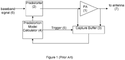
- Figure 1 a known DPD system is illustrated in Figure 1 and described below for a full understanding of the embodiments.
- DPD systems are often employed in communications system transmitters to allow a non-linear power amplifier to be driven into its non-linear region.
- a baseband signal 6 is processed by a predistorter 2.
- the predistorter 2 creates a signal that is forwarded to the power amplifier 1.
- the power amplifier 1 is the so-called baseband representation of the power amplifier 1. It is known that in an actual communications system, the baseband signal going to the power amplifier 1 would be up-converted in frequency to the transmission medium's carrier frequency for transmission where it would be amplified by the power amplifier 1. Furthermore, to observe the output of the power amplifier 1, the output of the power amplifier 1 would be down-converted back to a baseband signal and then sampled. Because all of these operations, such as up-conversion, downconversion, sampling, and D/A conversion, are not relevant to the description of exemplary embodiments, the power amplifier 1 is modeled by its so-called baseband representation.
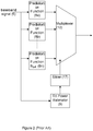
- Figure 2 illustrates a detailed representation of a known predistorter 2.
- An incoming baseband signal 6 is sent through a total of N pdf predistortion functions 8.
- different predistortion functions 8 are typically needed to correct power amplifier performance at different transmission power levels.
- a first predistortion function 8a may be used to linearize the power amplifier 1 when the power amplifier 1 is transmitting at an average transmission power level greater than P max - 0.5dB, where P max indicates the maximum average transmission power that the power amplifier 1 is expected to transmit.
- a second predistortion function 8b may be used to linearize the non-linear power amplifier 1 when it is transmitting at a power level between P max - 1.5dB and P max - 0.5dB.
- N pdf the number of used predistortion functions depends on the power amplifier being used. For example, in a well-behaved non-linear power amplifier, a single predistortion function may be able to linearize the non-linear power amplifier through a wide range of average transmission power values. For example, a single function may be able to linearize a particular power amplifier model for all average transmission powers greater than P max -4dB. However, a different predistortion function may be required by the same power amplifier for average transmission powers between P max -4dB and P max -8dB.
- a different non-linear power amplifier model may not be so well behaved and may require predistortion functions for transmission power ranges spaced 1dB apart.
- each predistortion function is responsible for linearizing the power amplifier when the power amplifier is transmitting within a specific transmission power range. Therefore, for every possible average transmission power, there will only be one predistortion function responsible for linearization.
- the particular predistortion function 8 used is determined by the actions of a power estimator 9, a slicer 17, and a multiplexer 10.
- the power estimator 9 produces estimates of the baseband signal power or, in effect, the non-linear power amplifier's transmit power.
- Several algorithms are generally known that can be used to estimate the power of a signal. In one particular algorithm, the average of the square of the absolute value of several samples is computed. The number of samples to be averaged varies depending on the desired accuracy of the power estimator. In another algorithm, the square of the absolute value of the signal may be sent through an alpha filter which performs long term averaging. By adjusting the alpha value of the filter, more averaging can be used to produce more accurate estimates of the power of the signal.
- the power estimates are forwarded to the slicer 17 which examines the power estimate and determines which predistortion function is responsible for linearizing the power amplifier 1 at that particular transmission power level.
- the input to the slicer 17 is the current estimated power value, and the output is a number between 1 and N pdf , indicating which predistortion function 8 should be used to predistort the power amplifier 1.
- a predistortion model calculator 4 sends a signal to a capture buffer 3 indicating that the capture buffer 3 should capture and record data going into the power amplifier 1 and the data coming out of the power amplifier 1.
- the capture buffer 3 Upon receipt of a trigger signal 5, the capture buffer 3 begins recording samples into its memory buffer until it has recorded an appropriate number of samples. The amount of data to record will vary based on different types and models of power amplifiers, but will typically be in the range of several thousand samples.
- the predistortion model calculator 4 After the capture buffer 3 finishes the data capturing, the predistortion model calculator 4 reads the data from the memory buffer and processes the data so as to update the predistortion functions 8.
- a simple algorithm is a memory-less polynomial algorithm which models the power amplifier 1 as a memory-less nonlinear device.
- the predistortion model calculator 4 can calculate the nonlinear performance of the power amplifier 1 and then calculate an inverse mapping to counteract the nonlinear effects of the power amplifier 1. This inverse mapping is then used as a predistortion function 8.
- the predistortion function 8 that is updated is chosen based on the average power of the signal coming out of the power amplifier.
- the predistortion function which will be updated is the predistortion function which is responsible for linearizing the power amplifier 1 at the power level that was measured on the output of the power amplifier.
- the predistortion model calculator 4 is often implemented as a digital signal processor and operates at a very slow rate. For instance, the sampling rate of the data going through the DPD system might be on the order of several 100MHz. However, the predistortion model calculator 4 often operates at a speed that is many orders of magnitude slower than 100MHz. Consequently, although the clock rate of the DSP may also be several 100MHz, a single predistortion function update may take between 1 and 10 seconds to complete.
- FIG 3 illustrates an example of a system that may be used to solve these limitations of the prior art DPD system.
- a baseband signal 6 is processed by a predistorter 2 which creates a signal which is sent to a power amplifier 1.
- the characteristics of the power amplifier 1 change with time and it is necessary to periodically update the characteristics of the predistorter 2.
- an intelligent predistortion model calculator 21 programs a set of priority codes and then sends a signal 22 to the intelligent trigger module 11 that it should begin to search for data to capture from the power amplifier 1.
- the predistortion model calculator 21 processes the data so as to update predistortion functions that correspond to characteristics of the power amplifier 1.
- the intelligent trigger module 11 may operate when the intelligent predistortion model calculator 21 indicates that a search should be performed though the use of the search signal 22. This signal may be, for example, an active high signal. If the intelligent predistortion model calculator 21 transmits the signal 22 which indicates to the intelligent trigger module 11 that the value for the search signal 22 is, for example TRUE, the intelligent trigger module 11 will begin searching for data to capture and will not stop searching for data to capture until it receives a value for the search signal 22 that is FALSE from the intelligent predistortion model calculator 21.
- the intelligent trigger module 11 when the received value for the search signal 22 is FALSE, the intelligent trigger module 11 becomes inactive and does not perform any new captures. Any data captures that were in progress when the value for the received search signal 22 changes from TRUE to FALSE are discarded, but any data captures that were successfully completed before the transition are retained.
- a baseband signal 6 is sent to a power estimator 23 which averages the instantaneous power of several samples so as to produce an estimate of the current transmission power 16 of the power amplifier 1 during each measurement period.
- the actual length of the measurement period may be chosen by the designer of the system as a tradeoff between estimation accuracy and estimation delay.
- the power estimator 23 is not allowed to average transmission power measurements between measurement periods. For every measurement period, the power estimator 23 produces a single estimate 16 that is independent of the estimates that it previously produced.
- the estimate of the current transmission power 16 is sent to a power-is-constant module 13 which monitors the average power estimates.
- a power_is_constant signal 15 is initialized to a FALSE value.
- the power-is-constant module 13 waits for the first power estimate 16 from the transmission power estimator 23 and the power-is-constant module 13 initializes an average power signalto be equal to the value of the first power estimate 16.
- the power-is-constant module 13 then enters a main loop.
- the power-is-constant module 13 waits for the next power estimate 16 to arrive from the power estimation module 23.
- the next power estimate value 16 is compared against the stored average power value to determine if the average signal power being sent through the power amplifier has changed significantly. This is done by the use of two constants, dep_high and dep_low.
- the dep_high and dep_low constants determine the highest estimated transmission power and the lowest estimated transmission power, respectively, that are allowed before the system considers that the transmission power is no longer being held constant.
- dep_high is set to 1.122 and dep_low is set to 0.891, the system will allow the estimated power to vary from the average power by up to 0.5dB in either direction before it forces the value of power_is_constant value signal 15 to be FALSE.
- an alpha filter will be used to average the power estimate values 16 as they arrive from the power estimation module 23.
- the alpha parameter is chosen so as to allow a certain amount of variation in the average transmission power of the power amplifier 1 before the power_is_constant value signal 15 is forced to be FALSE.
- a low value of alpha will cause an average power value to change very slowly and thus, only very slow changes in average transmission power will be accepted before the value of the power_is_constant value signal 15 is forced to be FALSE.
- a large value of alpha will cause the average power value to change relatively quickly and will allow more rapid average transmission power changes before the value of the power_is_constant value signal 15 is forced to be FALSE.
- the actual value of alpha is determined by the characteristics of the power amplifier and by the length of time the power amplifier takes to reach steady state when the transmission power changes. If the power amplifier 1 takes a long time to reach steady state, then a low value is used for alpha. If the power amplifier 1 reaches a steady state quickly, then a larger value of alpha may be used.
- the counter is checked to see if it is greater than or equal to the value of a pic_min_run_length field. If it is, the value of power_is_constant value signal 15 is set to TRUE which indicates that the power amplifier's transmission power has not changed significantly for at least pic_min_run_length T meas measurement periods. If the counter is less than pic_min_run_length, then this indicates that although the power amplifier's transmission power has been stable for several T meas measurement periods, not enough measurement periods have passed so as to consider the power amplifier to be in a steady state condition.
- the power-is-constant module 13 will continuously observe the power measurements and produce a signal 15 that indicates that the transmission power of the power amplifier has remained relatively constant for a reasonable amount of time. If the transmission power changes substantially, this module will immediately set the power_is_constant signal 15 to FALSE and wait for the transmission power to re-stabilize for a certain amount of time before it again sets the power_is_constant signal 15 to TRUE.
- dep_high, dep_low, alpha, pic_min_runlength, and T meas are chosen and adjusted based on the actual power amplifier that is in use.
- the value of the power_is_constant signal 15 is sent to a logical reasoning module 14 which decides when a capture should be initiated and whether the capture was completed successfully or not.
- Figure 5 illustrates an example of a logical reasoning module.
- a power estimate signal 16 first goes through a slicer module 17 as described above.
- the output of the slicer module 17 indicates which predistortion function corresponds to the power level of the power estimate signal 16.
- a priority code is stored in a predistortion function search priority module 18.
- the priority codes stored in the predistortion function search priority module 18 indicate to a trigger generator 19 the priority code of each of the predistortion functions 8, and this information is used by the trigger generator 19 to decide whether to begin a capture or not.
- the trigger generator 19 before any capture can be initiated, the trigger generator 19 first checks to see if a power_is_constant signal 15 is set to TRUE. If this signal is TRUE, the trigger generator 19 then checks the priority code of the predistortion function that appears on the output of the slicer 17. If the priority code of the function on the output of the slicer 17 is higher than the priority code of the data currently stored in the holding buffer (or if the holding buffer is empty), an advanced trigger signal is sent to the capture buffer 20, shown in Figure 3 , to indicate that it should begin capturing data.
- the power_is_constant value signal 15 While the data is being captured, the power_is_constant value signal 15 is continuously monitored to ensure that it remains TRUE. If the value of the power_is_constant value signal 15 changes to FALSE during the capture, the captured data is discarded and the trigger generator 19 returns to its waiting state where it waits for the power_is_constant value signal 15 to become TRUE again.
- the trigger generator 19 continues to monitor the power_is_constant value signal 15 for T HOLD seconds. Because of measurement errors and delays in the power estimation module 23, the transmission power of the power amplifier 1 may change. However, this change is not noted until slightly after the capture has been completed. By ensuring that power_is_constant value signal 15 remains TRUE for T HOLD seconds, one can ensure that the transmission power did not in fact change during any part of the capture.
- power_is_constant value signal 15 becomes FALSE before T HOLD seconds have elapsed, then the captured data is discarded and the trigger generator 19 again returns to its waiting state where it waits for the power_is_constant value signal 15 to become TRUE again. If the power_is_constant value signal 15 remains TRUE for the entire T HOLD period, this is considered a successful capture and the data stored in the capture buffer 20 is moved to the holding buffer. Furthermore, the priority code of the data stored in the holding buffer is also stored. The trigger generator 19 again returns to its waiting state where it waits for the power_is_constant value signal 15 to become TRUE again. Note that after a successful capture, a new capture will only be initiated if the power amplifier 1 starts transmitting at a power level whose predistortion function 8 has a priority code higher than the priority code of the data stored in the holding buffer.
- a DPD system is composed of three predistortion functions (8a, 8b, and 8c) that are responsible for predistortion for transmission power ranges [Inf,P max -4dB), [P max -4dB,P max -8dB), [P max -8dB,0] respectively where the notation [A,B) represents the range of values that are less than or equal to A and greater than B and the notation [A,B] represents the range of values that are less than or equal to A and greater than or equal to B.
- the priority codes of these predistortion functions are assigned the values 20, 10, and 15 respectively.
- the power amplifier is transmitting at a constant average power level of P max -12dB when a capture buffer search is initiated. Because at the moment of initiating a capture search the holding buffer is empty and the power_is_constant value signal 15 is set to TRUE, a capture will immediately begin and complete successfully.
- the priority code of the data stored in the holding buffer will be 15 because a transmission power level of P max -12dB corresponds to the third predistortion function 8c which has a priority code of 15.
- the power_is_constant value signal 15 changes to FALSE for a period of time as determined by the pic_min_run_length but will shortly return to the value TRUE.
- the trigger generator 19 will notice the TRUE value on the power_is_constant value signal 15 and will consider initiating a new capture but will not do so because the priority code of the predistortion function that is used for a transmission power of P max -6dB is only 10, which is lower than the priority code of the data stored in the holding buffer. Effectively, the data stored in the holding buffer is of more interest than the data currently being transmitted through the power amplifier. Hence, the data currently being transmitted through the power amplifier 1 is ignored.
- the transmission power changes one more time to P max .
- the power_is_constant value signal becomes FALSE for a period of time and again returns to TRUE.
- the trigger generator 19 will in fact initiate a new capture because the priority code of the predistortion function 8a that is used for a transmission power of P max is 20, which is higher than the priority code of the data stored in the holding buffer.
- the newly captured data will be copied to the holding buffer and the old data will be discarded. Effectively, the data being transmitted through the power amplifier 1 is of more interested than the data stored in the holding buffer. Hence, the new data will replace the old data. If, however, the capture is not completed successfully because the power_is_constant value 15 became FALSE, the holding buffer is not changed. Effectively, the data being transmitted through the power amplifier 1 was of more interest than the data stored in the holding buffer, but it was not possible to successfully capture the data. Hence, the data in the holding buffer is retained.
- the priority codes of the different predistortion functions 8 are determined by the intelligent predistortion model calculator 21.
- One simple but effective priority code assignment strategy is to assign priority codes based on the amount of time that has elapsed since a particular predistortion function 8 was updated. The longer the amount of time since the last update, the higher the priority code of that predistortion function 8.
- all of the predistortion functions 8 can be assigned a priority code of 0. Then, these priority codes can be updated as each predistortion function is updated, one at a time.
- the intelligent predistortion model calculator 21 sets the search signal to FALSE to indicate that searching should stop. It then examines the holding buffer to see if it contains valid data. Note that if the transmission of the power amplifier 1 is constantly changing, it is possible for the power_is_constant value signal 15 to never become TRUE and hence it is possible that data may never be captured. The intelligent predistortion model calculator 21 would then initiate a new search. If data is available, the intelligent predistortion model calculator 21 will read the data and calculate an updated predistortion function 8 as has been described in the prior art.
- One advantage of the exemplary embodiments is that data is not captured during a transient period in the power amplifier's behavior. For example, if the transmission power though the power amplifier is changing rapidly, no captures will be initiated until the average power amplifier transmission power has become stable for a certain period of time.
- exemplary embodiments will be able to capture interesting data that appears on the power amplifier for a short period of time. For example, if the power amplifier has been transmitting using predistortion function 8a for a long period of time and suddenly transmits using predistortion function 8b for a short period of time, exemplary embodiments will be able to react very rapidly and capture data to facilitate the update predistortion function 8b.
- FIG. 6 illustrates the steps implements in an exemplary embodiment.
- a baseband signal is received in a predistortion module comprising at least one predistortion function.
- the predistortion module applies one predistortion function to the baseband signal to produce a processed baseband signal.
- a model calculator programs priority codes for each predistortion function so that the processed baseband signal transmitted from the predistortion module corresponds to a transmission power of a power amplifier.
- the model calculator sends a trigger signal to indicate when data capture from the power amplifier should begin so as to collect data to be used in updating predistortion functions.
- a trigger module receives the trigger signal and initiates data capture from the power amplifier upon receipt of the trigger signal.
- the trigger module sends an advance trigger signal to a capture buffer to capture data from the power amplifier.
- the model calculator uses the capture data to update the predistortion functions. The processed baseband signal transmitted from the predistortion module to the power amplifier corrects performance of the power amplifier at different transmission power levels.
Landscapes
- Engineering & Computer Science (AREA)
- Power Engineering (AREA)
- Physics & Mathematics (AREA)
- Nonlinear Science (AREA)
- Microelectronics & Electronic Packaging (AREA)
- Computer Networks & Wireless Communication (AREA)
- Signal Processing (AREA)
- Amplifiers (AREA)
- Transmitters (AREA)
Description
- Priority is claimed to PCT Patent Application No.
PCT/CN2010/072008 filed April 21, 2010 PCT/CN2010/074095 filed June 18, 2010 - The field of the present disclosure is digital predistortion (DPD) systems, and in particular, to an improved capture buffer (CB) which is often used in DPD systems.
- DPD systems are often employed in communications system transmitters to allow a power amplifier to be driven into its non-linear region. In a typical DPD prior art system, a baseband signal is processed by a predistorter. The predistorter is a nonlinear device which creates a signal that is forwarded to the nonlinear power amplifier, such that the cascade of the nonlinear predistorter and the nonlinear power amplifier produces a system that is linear overall. Thus, the signal being sent from the nonlinear device to an antenna is simply a scaled up version of the signal that arrived from the baseband.
- The baseband signal comes in and is sent through a total of Npdf predistortion functions. Power amplifiers typically have different characteristics at different transmission power levels. Hence, different predistortion functions are typically needed to correct power amplifier performance at different transmission power levels. The number of predistortion functions (Npdf) depends on the power amplifier being used because different power amplifiers require a different number of predistortion functions. Each predistortion function is responsible for linearizing a power amplifier when the power amplifier is transmitting inside a specific transmission power range. For every possible average transmission power, there may be only a single predistortion function responsible for linearization.
- The particular predistortion function that is used is determined by the actions of a power estimator, a slicer, and a multiplexer. The power estimator produces estimates of the baseband signal power or, in effect, the power amplifier's transmit power. The power estimates are forwarded to the slicer which examines the power estimate and determines which predistortion function is responsible for linearizing the power amplifier at that particular transmission power level. The input to the slicer is the current estimated power value and the output is a number between 1 and Npdf indicating which predistortion function should be used to predistort the power amplifier.
- Often the characteristics of the power amplifier change with time and it is necessary to periodically update the characteristics of the predistorter. These periodic updates are under the control of a predistortion model calculator which first sends a signal to a capture buffer indicating that it should capture and record the data going into the power amplifier and the data coming out of the power amplifier. The capture buffer is rather simple and upon the receipt of a trigger signal, it begins blindly recording samples into its memory buffer until it has recorded the appropriate number of samples. The amount of data to record will vary based on different types and models of power amplifiers, but will typically be in the range of several thousand samples. After the capture buffer has finished capturing data, the predistortion model calculator reads the data from the memory buffer and then processes the data so as to update the predistortion functions.
- The predistortion function that is updated is chosen based on the average power of the signal coming out of the power amplifier. The predistortion function which will be updated is the predistortion function which is responsible for linearizing the power amplifier at the power level that was measured on the output of the power amplifier.
- A significant limitation with the prior art is that the trigger affects the capture of a random set of data. The trigger signal arrives at a random moment in time without any regard to the signal that is currently being sent through the power amplifier. For example, a power amplifier can often be linearized quite well when it is transmitting at a fixed average transmission power level for some time. If the transmission power level changes, after some time, it will also be possible to linearize the power amplifier at the new average transmission power level. However, during a change in transmission power from one level to another, there will be some time when the power amplifier's characteristics are transitioning from one power level to another. During these transient periods, the power amplifier behaves somewhat unpredictably and is rather difficult to linearize. Because of the random timing of the trigger signal, it is possible that the capture buffer will capture data during one of these transient periods. If data from one of these transient periods is used to update a predistortion function, that predistortion function will only be able to linearize data during a transition period. Therefore, if the power amplifier transmits data at a fixed transmission power, this predistortion function will not be able to linearize the power amplifier and poor performance will result.
- For the purposes of further explanation, suppose that a power amplifier has been transmitting at a transmission power level of Pmax for a long period of time. Further suppose that the transmission power changes to Pmax-5dB and that this particular power amplifier takes 1 ms to reach its new steady state. If data is captured after the transmission power has been reduced, but before the power amplifier has reached its new steady state, the captured data would describe the performance of the power amplifier during this transient state and cannot be used to create a predistortion function. It would therefore be beneficial if a mechanism existed that could prevent the capture buffer from capturing transient data.
- A further discrepancy with the prior art described above becomes apparent in a situation where the transmission power level may be stable for long periods of time, but the transmission power level can change abruptly for short periods of time. For example, in a lightly loaded WCDMA (Wideband Code Division Multiple Access) transmitter that supports a High Speed Downlink Power Amplifier (HSDPA), it is a regular occurrence that the power amplifier may transmit at a transmission power level of Pmax-10dB for an extended period of time. If a mobile station is scheduled to receive a downlink transmission that is rather short in length, it is possible for the transmission power to suddenly jump to Pmax for a short amount of time (perhaps 2ms) and then drop back down to Pmax - 10dB after the transmission to the mobile station has been completed.
- With a random trigger, the probability of capturing data while the power amplifier is transmitting at Pmax is very low. For example, if these 2 ms transmissions only appear once per second, the probability of capturing data while the power amplifier is transmitting at Pmax is only about 1 in 500. This is a problem because the predistortion functions need to be updated regularly as the power amplifier's characteristics change. If the predistortion function that is used at a transmission power of Pmax is not updated regularly, the power amplifier may slowly lose performance at that transmission power level resulting in a decreased capacity and increased adjacent channel interference.
- Therefore, it would also be beneficial if a mechanism existed that would ensure that predistortion functions that have not been trained in a long time be properly updated, even if data to update these predistortion functions is difficult to find. The document
US 2008/157870 A1 discloses an approach for determining corrective predistortion functions includes maintaining a history of recent estimations of a plurality of corrective predistortion functions. Each of those functions corresponds to a respective signal characteristic. By determining a feature of each of those functions from the history, one of the corrective predistortion functions is selected for a next estimation based upon which of the functions has a feature within the history that satisfies a selected criteria. The documentEP 1681771 A1 discloses a radio-frequency (RF) transmitter power amplifier circuit which provides for practically linear performance by predistorting the amplifier input signals to compensate for amplifier distortion at high power levels, and provides a fine degree of control of amplifier power needed to handle complex modulation schemes with widely and rapidly varying power requirements. The documentUS 2008/243899 A1 discloses a system performs digital pre-distortion using gain values stored in a lookup table, and a method for performing digital pre-distortion includes identifying a lookup table entry, based on input data, and updating the lookup table entry by writing an updated gain value into the lookup table entry. - A system comprises: a predistortion module comprising at least one predistortion function, the predistortion module configured to: receive a baseband signal; and process the baseband signal; a power amplifier configured to receive a processed baseband signal transmitted from the predistortion module; a model calculator configured to: program priorities for each of the at least one predistortion functions, and send a search signal; and a trigger module configured to: in response to receipt of the search signal with a true value, begin to search for data to capture from the power amplifier, and send a trigger signal to a capture buffer, wherein the capture buffer captures data from the power amplifier; wherein the trigger module is configured to continue searching for data to capture until it receives the search signal with a false value; wherein the trigger module comprises: a power estimator configured to produce a power estimate of a transmission power of the power amplifier for each measurement period; a power constant module configured to: determine whether there is a pre-determined level of change in an average power signal of the power estimates of the transmission power of the power amplifier, and produce a constant value signal to either indicate that the transmission power of the power amplifier is constant for a pre-determined length of time or to indicate a pre-determined level of change in the transmission power of the power amplifier over the pre-determined length of time; and a logic module configured to: receive the constant value signal, and determine whether a data capture is to be initiated, wherein data capture is not initiated when the constant value signal indicates the pre-determined level of change in the transmission power of the power amplifier over the pre-determined length of time.
- A method comprises: receiving, by a predistortion module, a baseband signal, the predistortion module comprising at least one predistortion function; programming a priority code for each of the at least one predistortion functions so that a processed baseband signal transmitted from the predistortion module corresponds to a transmission power of a power amplifier; sending, by a model calculator, a search signal to indicate when to capture data from the power amplifier; in response to receiving the search signal with a true value at a trigger module, beginning to search for data to capture from the power amplifier and continuing searching for data to capture until receiving the search signal with a false value; sending, by the trigger module, a trigger signal to a capture buffer to capture data from the power amplifier; and using the captured data to update the at least one predistortion functions, wherein the at least one updated predistortion functions are periodically applied to the processed baseband signal transmitted to the power amplifier to correct performance of the power amplifier at corresponding transmission power levels; wherein the searching for data to capture comprises: receiving the baseband signal; producing an estimate of a transmission power of the power amplifier for each measurement period; receiving the power estimate and determining whether there is a pre-determined level of change in an average power signal of the power estimates of the transmission power of the power amplifier; producing a constant value signal to either indicate that the transmission power of the power amplifier is relatively constant for a predetermined length of time or to indicate a pre-determined level of change in the transmission power of the power amplifier over the predetermined length of time; receiving the constant value signal; determining whether the data capture is to be initiated, wherein data capture is not initated when the constant value signal indicates the pre-determined level of change in the transmission power of the power amplifier over the pre-determined length of time.
-
-
Figure 1 illustrates an example of a typical digital predistortion (DPD) system as is known in the art; -
Figure 2 illustrates a detailed representation of a predistorter as is known in the art, for use in known DPD systems; -
Figure 3 illustrates an example of an improved DPD system; -
Figure 4 illustrates an intelligent trigger module for use in a DPD system; -
Figure 5 illustrates a logical reasoning module for use in a DPD system; and -
Figure 6 illustrates processing steps implemented in a DPD system. - Exemplary embodiments are directed to an improved capture buffer used in digital predistortion (DPD) systems. In order to fully describe the exemplary embodiments, a known DPD system is illustrated in
Figure 1 and described below for a full understanding of the embodiments. As is known to those skilled in the art, DPD systems are often employed in communications system transmitters to allow a non-linear power amplifier to be driven into its non-linear region. Abaseband signal 6 is processed by apredistorter 2. Thepredistorter 2 creates a signal that is forwarded to thepower amplifier 1. - Note that in
Fig. 1 , thepower amplifier 1 is the so-called baseband representation of thepower amplifier 1. It is known that in an actual communications system, the baseband signal going to thepower amplifier 1 would be up-converted in frequency to the transmission medium's carrier frequency for transmission where it would be amplified by thepower amplifier 1. Furthermore, to observe the output of thepower amplifier 1, the output of thepower amplifier 1 would be down-converted back to a baseband signal and then sampled. Because all of these operations, such as up-conversion, downconversion, sampling, and D/A conversion, are not relevant to the description of exemplary embodiments, thepower amplifier 1 is modeled by its so-called baseband representation. -
Figure 2 illustrates a detailed representation of a knownpredistorter 2. Anincoming baseband signal 6 is sent through a total of Npdf predistortion functions 8. Because power amplifiers typically have different characteristics at different transmission power levels, different predistortion functions 8 are typically needed to correct power amplifier performance at different transmission power levels. For example, afirst predistortion function 8a may be used to linearize thepower amplifier 1 when thepower amplifier 1 is transmitting at an average transmission power level greater than Pmax - 0.5dB, where Pmax indicates the maximum average transmission power that thepower amplifier 1 is expected to transmit. Asecond predistortion function 8b may be used to linearize thenon-linear power amplifier 1 when it is transmitting at a power level between Pmax - 1.5dB and Pmax - 0.5dB. - Because different power amplifiers require a different number of predistortion functions, the number of used predistortion functions (Npdf) depends on the power amplifier being used. For example, in a well-behaved non-linear power amplifier, a single predistortion function may be able to linearize the non-linear power amplifier through a wide range of average transmission power values. For example, a single function may be able to linearize a particular power amplifier model for all average transmission powers greater than Pmax-4dB. However, a different predistortion function may be required by the same power amplifier for average transmission powers between Pmax-4dB and Pmax-8dB. A different non-linear power amplifier model may not be so well behaved and may require predistortion functions for transmission power ranges spaced 1dB apart. Thus, each predistortion function is responsible for linearizing the power amplifier when the power amplifier is transmitting within a specific transmission power range. Therefore, for every possible average transmission power, there will only be one predistortion function responsible for linearization.
- The particular predistortion function 8 used is determined by the actions of a
power estimator 9, aslicer 17, and amultiplexer 10. Thepower estimator 9 produces estimates of the baseband signal power or, in effect, the non-linear power amplifier's transmit power. Several algorithms are generally known that can be used to estimate the power of a signal. In one particular algorithm, the average of the square of the absolute value of several samples is computed. The number of samples to be averaged varies depending on the desired accuracy of the power estimator. In another algorithm, the square of the absolute value of the signal may be sent through an alpha filter which performs long term averaging. By adjusting the alpha value of the filter, more averaging can be used to produce more accurate estimates of the power of the signal. - The power estimates are forwarded to the
slicer 17 which examines the power estimate and determines which predistortion function is responsible for linearizing thepower amplifier 1 at that particular transmission power level. The input to theslicer 17 is the current estimated power value, and the output is a number between 1 and Npdf, indicating which predistortion function 8 should be used to predistort thepower amplifier 1. - Returning to
Figure 1 , because the characteristics of thepower amplifier 1 change with time, it is sometimes necessary to periodically update the characteristics of thepredistorter 2. Thus, apredistortion model calculator 4 sends a signal to acapture buffer 3 indicating that thecapture buffer 3 should capture and record data going into thepower amplifier 1 and the data coming out of thepower amplifier 1. Upon receipt of atrigger signal 5, thecapture buffer 3 begins recording samples into its memory buffer until it has recorded an appropriate number of samples. The amount of data to record will vary based on different types and models of power amplifiers, but will typically be in the range of several thousand samples. - After the
capture buffer 3 finishes the data capturing, thepredistortion model calculator 4 reads the data from the memory buffer and processes the data so as to update the predistortion functions 8. Several algorithms exist whereby the captured data can be analyzed and used to update the predistortion functions 8. For example, a simple algorithm is a memory-less polynomial algorithm which models thepower amplifier 1 as a memory-less nonlinear device. By analyzing the input and output data of thepower amplifier 1, thepredistortion model calculator 4 can calculate the nonlinear performance of thepower amplifier 1 and then calculate an inverse mapping to counteract the nonlinear effects of thepower amplifier 1. This inverse mapping is then used as a predistortion function 8. - The predistortion function 8 that is updated is chosen based on the average power of the signal coming out of the power amplifier. The predistortion function which will be updated is the predistortion function which is responsible for linearizing the
power amplifier 1 at the power level that was measured on the output of the power amplifier. Thepredistortion model calculator 4 is often implemented as a digital signal processor and operates at a very slow rate. For instance, the sampling rate of the data going through the DPD system might be on the order of several 100MHz. However, thepredistortion model calculator 4 often operates at a speed that is many orders of magnitude slower than 100MHz. Consequently, although the clock rate of the DSP may also be several 100MHz, a single predistortion function update may take between 1 and 10 seconds to complete. -
Figure 3 illustrates an example of a system that may be used to solve these limitations of the prior art DPD system. Similar to the system illustrated inFigure 1 , abaseband signal 6 is processed by apredistorter 2 which creates a signal which is sent to apower amplifier 1. Often, the characteristics of thepower amplifier 1 change with time and it is necessary to periodically update the characteristics of thepredistorter 2. When it is time to analyze power amplifier performance to update thepredistorter 2, an intelligent predistortion model calculator 21 programs a set of priority codes and then sends asignal 22 to theintelligent trigger module 11 that it should begin to search for data to capture from thepower amplifier 1. After data from thepower amplifier 1 is successfully captured, the predistortion model calculator 21 processes the data so as to update predistortion functions that correspond to characteristics of thepower amplifier 1. - The
intelligent trigger module 11 may operate when the intelligent predistortion model calculator 21 indicates that a search should be performed though the use of thesearch signal 22. This signal may be, for example, an active high signal. If the intelligent predistortion model calculator 21 transmits thesignal 22 which indicates to theintelligent trigger module 11 that the value for thesearch signal 22 is, for example TRUE, theintelligent trigger module 11 will begin searching for data to capture and will not stop searching for data to capture until it receives a value for thesearch signal 22 that is FALSE from the intelligent predistortion model calculator 21. - Therefore, in an exemplary embodiment, when the received value for the
search signal 22 is FALSE, theintelligent trigger module 11 becomes inactive and does not perform any new captures. Any data captures that were in progress when the value for the receivedsearch signal 22 changes from TRUE to FALSE are discarded, but any data captures that were successfully completed before the transition are retained. - Referring to
Figure 4 illustrating an example of theintelligent trigger module 11, abaseband signal 6 is sent to apower estimator 23 which averages the instantaneous power of several samples so as to produce an estimate of thecurrent transmission power 16 of thepower amplifier 1 during each measurement period. The longer the measurement period (Tmeas), the more accurate the power estimates, but also the longer amount of time that it will take to produce a new estimate of thetransmission power 16. The actual length of the measurement period may be chosen by the designer of the system as a tradeoff between estimation accuracy and estimation delay. - In one exemplary embodiment, the
power estimator 23 is not allowed to average transmission power measurements between measurement periods. For every measurement period, thepower estimator 23 produces asingle estimate 16 that is independent of the estimates that it previously produced. - The estimate of the
current transmission power 16 is sent to a power-is-constant module 13 which monitors the average power estimates. When the power-is-constant module 13 first begins searching, apower_is_constant signal 15 is initialized to a FALSE value. The power-is-constant module 13 waits for thefirst power estimate 16 from thetransmission power estimator 23 and the power-is-constant module 13 initializes an average power signalto be equal to the value of thefirst power estimate 16. The power-is-constant module 13 then enters a main loop. - Inside this main loop, the power-is-
constant module 13 waits for thenext power estimate 16 to arrive from thepower estimation module 23. The nextpower estimate value 16 is compared against the stored average power value to determine if the average signal power being sent through the power amplifier has changed significantly. This is done by the use of two constants, dep_high and dep_low. The dep_high and dep_low constants determine the highest estimated transmission power and the lowest estimated transmission power, respectively, that are allowed before the system considers that the transmission power is no longer being held constant. For example, if dep_high is set to 1.122 and dep_low is set to 0.891, the system will allow the estimated power to vary from the average power by up to 0.5dB in either direction before it forces the value ofpower_is_constant value signal 15 to be FALSE. - If a single power estimate value is outside of the range determined by average power field, dep_high, and dep_low, the value of power_is_constant signalis set to FALSE, a counter is set to 0, and average power signalis re-initialized to the current power estimate. If the current
power estimate value 16 is within the range determined by average power field, dep_high, and dep_low, the counter is increased by 1 and the value of the average power signalis updated according to the following equation:
- In other words, an alpha filter will be used to average the power estimate values 16 as they arrive from the
power estimation module 23. The alpha parameter is chosen so as to allow a certain amount of variation in the average transmission power of thepower amplifier 1 before thepower_is_constant value signal 15 is forced to be FALSE. A low value of alpha will cause an average power value to change very slowly and thus, only very slow changes in average transmission power will be accepted before the value of thepower_is_constant value signal 15 is forced to be FALSE. A large value of alpha will cause the average power value to change relatively quickly and will allow more rapid average transmission power changes before the value of thepower_is_constant value signal 15 is forced to be FALSE. - The actual value of alpha is determined by the characteristics of the power amplifier and by the length of time the power amplifier takes to reach steady state when the transmission power changes. If the
power amplifier 1 takes a long time to reach steady state, then a low value is used for alpha. If thepower amplifier 1 reaches a steady state quickly, then a larger value of alpha may be used. - After the average power value is updated, the counter is checked to see if it is greater than or equal to the value of a pic_min_run_length field. If it is, the value of
power_is_constant value signal 15 is set to TRUE which indicates that the power amplifier's transmission power has not changed significantly for at least pic_min_run_length Tmeas measurement periods. If the counter is less than pic_min_run_length, then this indicates that although the power amplifier's transmission power has been stable for several Tmeas measurement periods, not enough measurement periods have passed so as to consider the power amplifier to be in a steady state condition. - Therefore, the power-is-
constant module 13 will continuously observe the power measurements and produce asignal 15 that indicates that the transmission power of the power amplifier has remained relatively constant for a reasonable amount of time. If the transmission power changes substantially, this module will immediately set thepower_is_constant signal 15 to FALSE and wait for the transmission power to re-stabilize for a certain amount of time before it again sets thepower_is_constant signal 15 to TRUE. - The parameters dep_high, dep_low, alpha, pic_min_runlength, and Tmeas are chosen and adjusted based on the actual power amplifier that is in use. As an example, a WCDMA power amplifier that recovers relatively quickly from rapid power changes may be able to use the following values: dep_high=1.122, dep_low=0.891, alpha=0.8, pic_min_run length=3, and Tmeas=0.1ms.
- The value of the
power_is_constant signal 15 is sent to alogical reasoning module 14 which decides when a capture should be initiated and whether the capture was completed successfully or not. -
Figure 5 illustrates an example of a logical reasoning module. Apower estimate signal 16 first goes through aslicer module 17 as described above. The output of theslicer module 17 indicates which predistortion function corresponds to the power level of thepower estimate signal 16. For each predistortion function, a priority code is stored in a predistortion functionsearch priority module 18. The priority codes stored in the predistortion functionsearch priority module 18 indicate to atrigger generator 19 the priority code of each of the predistortion functions 8, and this information is used by thetrigger generator 19 to decide whether to begin a capture or not. - According to exemplary embodiments, before any capture can be initiated, the
trigger generator 19 first checks to see if apower_is_constant signal 15 is set to TRUE. If this signal is TRUE, thetrigger generator 19 then checks the priority code of the predistortion function that appears on the output of theslicer 17. If the priority code of the function on the output of theslicer 17 is higher than the priority code of the data currently stored in the holding buffer (or if the holding buffer is empty), an advanced trigger signal is sent to thecapture buffer 20, shown inFigure 3 , to indicate that it should begin capturing data. - While the data is being captured, the
power_is_constant value signal 15 is continuously monitored to ensure that it remains TRUE. If the value of the power_is_constant value signal 15 changes to FALSE during the capture, the captured data is discarded and thetrigger generator 19 returns to its waiting state where it waits for thepower_is_constant value signal 15 to become TRUE again. - After the data capture has been completed, the
trigger generator 19 continues to monitor thepower_is_constant value signal 15 for THOLD seconds. Because of measurement errors and delays in thepower estimation module 23, the transmission power of thepower amplifier 1 may change. However, this change is not noted until slightly after the capture has been completed. By ensuring thatpower_is_constant value signal 15 remains TRUE for THOLD seconds, one can ensure that the transmission power did not in fact change during any part of the capture. - If
power_is_constant value signal 15 becomes FALSE before THOLD seconds have elapsed, then the captured data is discarded and thetrigger generator 19 again returns to its waiting state where it waits for thepower_is_constant value signal 15 to become TRUE again. If thepower_is_constant value signal 15 remains TRUE for the entire THOLD period, this is considered a successful capture and the data stored in thecapture buffer 20 is moved to the holding buffer. Furthermore, the priority code of the data stored in the holding buffer is also stored. Thetrigger generator 19 again returns to its waiting state where it waits for thepower_is_constant value signal 15 to become TRUE again. Note that after a successful capture, a new capture will only be initiated if thepower amplifier 1 starts transmitting at a power level whose predistortion function 8 has a priority code higher than the priority code of the data stored in the holding buffer. - For example, suppose that a DPD system is composed of three predistortion functions (8a, 8b, and 8c) that are responsible for predistortion for transmission power ranges [Inf,Pmax-4dB), [Pmax-4dB,Pmax-8dB), [Pmax-8dB,0] respectively where the notation [A,B) represents the range of values that are less than or equal to A and greater than B and the notation [A,B] represents the range of values that are less than or equal to A and greater than or equal to B. Furthermore, suppose that the priority codes of these predistortion functions are assigned the
values power_is_constant value signal 15 is set to TRUE, a capture will immediately begin and complete successfully. The priority code of the data stored in the holding buffer will be 15 because a transmission power level of Pmax-12dB corresponds to the third predistortion function 8c which has a priority code of 15. - Now, suppose that the transmission power changes to Pmax-6dB. The power_is_constant value signal 15 changes to FALSE for a period of time as determined by the pic_min_run_length but will shortly return to the value TRUE. The
trigger generator 19 will notice the TRUE value on thepower_is_constant value signal 15 and will consider initiating a new capture but will not do so because the priority code of the predistortion function that is used for a transmission power of Pmax-6dB is only 10, which is lower than the priority code of the data stored in the holding buffer. Effectively, the data stored in the holding buffer is of more interest than the data currently being transmitted through the power amplifier. Hence, the data currently being transmitted through thepower amplifier 1 is ignored. - Finally, suppose that the transmission power changes one more time to Pmax. Again, the power_is_constant value signal becomes FALSE for a period of time and again returns to TRUE. This time however, the
trigger generator 19 will in fact initiate a new capture because the priority code of thepredistortion function 8a that is used for a transmission power of Pmax is 20, which is higher than the priority code of the data stored in the holding buffer. - If the capture is completed successfully (i.e.,
power_is_constant value 15 is TRUE throughout the capture and for THOLD seconds after the capture), the newly captured data will be copied to the holding buffer and the old data will be discarded. Effectively, the data being transmitted through thepower amplifier 1 is of more interested than the data stored in the holding buffer. Hence, the new data will replace the old data. If, however, the capture is not completed successfully because thepower_is_constant value 15 became FALSE, the holding buffer is not changed. Effectively, the data being transmitted through thepower amplifier 1 was of more interest than the data stored in the holding buffer, but it was not possible to successfully capture the data. Hence, the data in the holding buffer is retained. - It should be noted that the priority codes of the different predistortion functions 8 are determined by the intelligent predistortion model calculator 21. One simple but effective priority code assignment strategy is to assign priority codes based on the amount of time that has elapsed since a particular predistortion function 8 was updated. The longer the amount of time since the last update, the higher the priority code of that predistortion function 8. When the system is first powered up, all of the predistortion functions 8 can be assigned a priority code of 0. Then, these priority codes can be updated as each predistortion function is updated, one at a time.
- After a certain amount of time, the intelligent predistortion model calculator 21 sets the search signal to FALSE to indicate that searching should stop. It then examines the holding buffer to see if it contains valid data. Note that if the transmission of the
power amplifier 1 is constantly changing, it is possible for thepower_is_constant value signal 15 to never become TRUE and hence it is possible that data may never be captured. The intelligent predistortion model calculator 21 would then initiate a new search. If data is available, the intelligent predistortion model calculator 21 will read the data and calculate an updated predistortion function 8 as has been described in the prior art. - One advantage of the exemplary embodiments is that data is not captured during a transient period in the power amplifier's behavior. For example, if the transmission power though the power amplifier is changing rapidly, no captures will be initiated until the average power amplifier transmission power has become stable for a certain period of time.
- Furthermore, exemplary embodiments will be able to capture interesting data that appears on the power amplifier for a short period of time. For example, if the power amplifier has been transmitting using
predistortion function 8a for a long period of time and suddenly transmits usingpredistortion function 8b for a short period of time, exemplary embodiments will be able to react very rapidly and capture data to facilitate theupdate predistortion function 8b. -
Figure 6 illustrates the steps implements in an exemplary embodiment. In Step, 6010, a baseband signal is received in a predistortion module comprising at least one predistortion function. InStep 6020, the predistortion module applies one predistortion function to the baseband signal to produce a processed baseband signal. InStep 6030, a model calculator programs priority codes for each predistortion function so that the processed baseband signal transmitted from the predistortion module corresponds to a transmission power of a power amplifier. InStep 6040, the model calculator sends a trigger signal to indicate when data capture from the power amplifier should begin so as to collect data to be used in updating predistortion functions. InStep 6050, a trigger module receives the trigger signal and initiates data capture from the power amplifier upon receipt of the trigger signal. InStep 6060, the trigger module sends an advance trigger signal to a capture buffer to capture data from the power amplifier. InStep 6070, the model calculator uses the capture data to update the predistortion functions. The processed baseband signal transmitted from the predistortion module to the power amplifier corrects performance of the power amplifier at different transmission power levels. - While exemplary embodiments have been shown and described, it will be apparent to those skilled in the art that many more modifications are possible without departing from the inventive concepts herein. The disclosure, therefore, is not to be restricted except in the spirit of the following claims.
Claims (14)
- A system, comprising:a predistortion module (2) comprising at least one predistortion function, the predistortion module (2) configured to:receive a baseband signal (6); andprocess the baseband signal (6);a power amplifier (1) configured to receive a processed baseband signal transmitted from the predistortion module (2);characterized by further comprising:a model calculator (21) configured to:program priorities for each of the at least one predistortion functions, andsend a search signal (22); anda trigger module (11) configured to:in response to receipt of the search signal (22) with a true value, begin to search for data to capture from the power amplifier (1), andsend a trigger signal (12) to a capture buffer (20), wherein the capture buffer (20) captures data from the power amplifier (1);wherein the trigger module (11) is configured to continue searching for data to capture until it receives the search signal with a false value;wherein the trigger module (11) comprises:a power estimator (23) configured to produce a power estimate (16) of a transmission power of the power amplifier (1) for each measurement period;a power constant module (13) configured to:determine whether there is a pre-determined level of change in an average power signal of the power estimates (16) of the transmission power of the power amplifier (1), andproduce a constant value signal (15) to either indicate that the transmission power of the power amplifier (1) is constant for a pre-determined length of time or to indicate a pre-determined level of change in the transmission power of the power amplifier (1) over the pre-determined length of time; anda logic reasoning module (14) configured to:receive the constant value signal (15), anddetermine whether a data capture of the power amplifier is to be initiated, wherein data capture is not initiated when the constant value signal (15) indicates the pre-determined level of change in the transmission power of the power amplifier (1) over the pre-determined length of time.
- The system of claim 1, wherein the each of the at least one predistortion functions is applied to the processed baseband signal;
or
the model calculator (21) is configured to determine priority codes based on an elapsed time since a at least one predistortion function was last updated. - The system of claim 1, wherein the trigger module (11) is further configured to discard data in the process of being captured when the false value for the search signal is received, and the trigger module (11) is further configured to retain data captured before the false value for the search signal is received.
- The system of claim 1, wherein the power estimator (23) is further configured to produce the power estimate (16) by averaging instantaneous power of at least two samples.
- The system of claim 1, wherein the power constant module (13) is configured to monitor the average power estimates (16) by:initializing a power constant signal to a false value;initializing an average power signal to a first power estimate received from the power estimator (23); andentering a loop,wherein, in the loop, the power constant module (13) is configured to:wait to receive a next power estimate value from the power estimator (23);compare the value of next power estimate to the value of the average power signal to determine if there is a predetermined level of change in the average power signal being sent through the power amplifier;if the next power estimate value is outside of a predefined range:set the power constant signal to a false value,set a counter to zero, andinitialize the average power signal to the next power estimate value, orif the next power estimate value is within a predefined range:wherein the value of the average power signal is updated by applying an alpha filter to average power estimate values received from the power estimator (23), and wherein the alpha filter value is chosen so as to allow a certain type of variation in average transmission power from the power amplifier (1) before the power constant signal is set to a false value; or the power constant module (13) is configured to determine if there is a predetermined level of change in the average power signal by determining if the next power estimate is between a highest estimated transmission power and a lowest estimated transmission power, and wherein a transmission power is no longer considered to be constant if it is outside a range of the highest estimated transmission power and the lowest estimated transmission power.increase the counter value,update the value of the average power field,determine that the counter value is greater than or equal to a value of a predefined length field, andset the power constant signal to a true value to indicate that transmission power from the power amplifier (1) has not changed for a predefined measurement period;
- The system of claim 1, wherein the logic module comprises:a slicer (17) configured to:receive the power estimate (16) from the power estimator (23), andoutput a signal indicating that the each of the at least one predistortion functions corresponds to the power level associated with the power estimate;a priority module (18) configured to store a priority code for the each of the at least one predistortion functions, wherein the priority codes are used to determine whether to initiate data capture; anda trigger generator (19) configured to:wherein the trigger generator (19) is configured to initiate data capturing upon determining that:receive the priority code and the constant value signal (15),
anddetermine whether to capture data from the power amplifier (1), based on the priority code and the constant value signal (15);the value of the constant value signal (15) is a true, and the priority code of the predistortion function is higher than the priority code of data currently stored in a holding buffer; or the trigger generator (19) is configured to terminate data capturing upon determining that the value of the constant value signal (15) is a false, and move to a waiting state until the value of the constant value signal (15) becomes positive. - A method, comprising:receiving (6010), by a predistortion module, a baseband signal, the predistortion module comprising at least one predistortion function;characterized by further comprising:programming (6030) a priority code for each of the at least one predistortion functions so that a processed baseband signal transmitted from the predistortion module corresponds to a transmission power of a power amplifier;sending (6040), by a model calculator, a search signal to indicate when to capture data from the power amplifier;in response to receiving the search signal with a true value at a trigger module, beginning to search for data to capture from the power amplifier and continuing searching for data to capture until receiving the search signal with a false value;sending (6060), by the trigger module, a trigger signal to a capture buffer to capture data from the power amplifier; andusing (6070) the captured data to update the at least one predistortion functions, wherein the at least one updated predistortion functions are periodically applied to the processed baseband signal transmitted to the power amplifier to correct performance of the power amplifier at corresponding transmission power levels;wherein the searching for data to capture comprises:receiving the baseband signal;producing an estimate of a transmission power of the power amplifier for each measurement period;receiving the power estimate and determining whether there is a pre-determined level of change in an average power signal of the power estimates (16) of the transmission power of the power amplifier;producing a constant value signal to either indicate that the transmission power of the power amplifier is relatively constant for a predetermined length of time or to indicate a pre-determined level of change in the transmission power of the power amplifier over the predetermined length of time;receiving the constant value signal;determining whether the data capture of the power amplifier is to be initiated, wherein data capture is not initated when the constant value signal (15) indicates the pre-determined level of change in the transmission power of the power amplifier (1) over the pre-determined length of time.
- The method of claim 7, wherein each of the at least one predistortion functions is applied to the processed baseband signal (6020);
or
the searching for data to capture further comprises: discarding data in the process of being captured when a false value for the search signal is received, or retaining data captured before the false value for the search signal is received. - The method of claim 7, wherein the searching for data to capture further comprises:if the data capture is initiated, determining whether the data capture is successful.
- The method of claim 7, wherein the producing an estimate of a current transmission power comprises producing the estimate by averaging instantaneous power of several samples;
or
the method further comprises: determining if there is a predetermined level of change in the average power signal by determining if the next power estimate is between a highest estimated transmission power and a lowest estimated transmission power, wherein a transmission power is no longer considered to be constant if it is outside a range of the a highest estimated transmission power and the lowest estimated transmission power;
or
wherein the monitoring average power estimates for a predetermined length of time comprises:initializing a power constant signal to a false value;initializing an average power signal to a first power estimate received from the power estimator; andentering a loop, wherein the loop comprises:waiting to receive a next power estimate value from the power estimator;comparing the value of the next power estimate to the value of the average power signal to determine if there is a predetermined level of change in the average power signal being sent through the power amplifier;if the next power estimate value is outside of a predefined range:setting the power constant signal to a false value;setting a counter to zero; andinitializing the average power signal to the next power estimate value; orif the next power estimate is within a predefined range:increasing the counter value;updating the value of the average power field;determining that the counter value is greater than or equal to a value of a predefined length field; andsetting the power constant signal to a true value to indicate that transmission power from the power amplifier has not changed for a predefined measurement period;wherein the method further comprises: updating a value of the average power signal by applying an alpha filter to average power estimate values received from the power estimator, wherein the alpha filter value is chosen to allow a certain type of variation in average transmission power from the power amplifier before the power constant signal is set to a false value. - The method of claim 7, wherein the determining whether the data capture is to be initiated comprises:receiving the power estimate from the power estimator and outputting a signal which indicates the at least one predistortion functions corresponding to the power level of the power estimate;storing a priority code for each of the at least one predistortion functions, wherein the priority codes are used to determine whether to initiate the data capture; andusing the priority code stored in the priority module and the constant value signal from the power constant module to determine whether or not to capture data from the power amplifier.
- The method of claim 11, wherein the determining whether the data capture is to be initiated from the power amplifier comprises sending a trigger signal to the capture buffer to initiate data capturing upon determining that:the value of the constancy signal is a true value, andthat the priority code of the each of the at least one predistortion functions is higher than the priority code of data currently stored in a holding buffer,orwherein the determining whether to initiate the data capture from the power amplifier comprises:in response to determining that the constant value signal is a false value: sending a trigger signal to the capture buffer to terminate data capturing, and moving to a waiting state until the value of the constant value signal becomes positive;
wherein, if a data capture is complete:moving stored data in the capture buffer to a holding buffer, and storing the priority code of the data in the holding buffer;or
wherein the determining whether to initiate the data capture comprises:monitoring the constant value signal for a predetermined period of hold time after data capture is complete, whereinif the value of the constant value signal changes to a false value during the predetermined period of hold time:orsending, by the trigger generator, the trigger signal to the capture buffer to terminate data capturing; andmoving to the waiting state until the value of the constant value signal becomes
positive;
wherein the determining whether to initiate the data capture comprises:in response to determining that a data capture is complete, initiating a new data capture process if the power amplifier begins to transit at a power level which the at least one predistortion function has a higher priority code than the data stored in a holding buffer. - An apparatus comprising means for carrying out the steps of the method of claim 7.
- The apparatus of claim 13, further comprising means for applying the at least one predistortion function to the baseband signal (6) to produce the processed baseband signal.
Applications Claiming Priority (3)
| Application Number | Priority Date | Filing Date | Title |
|---|---|---|---|
| CN2010072008 | 2010-04-21 | ||
| CN2010074095 | 2010-06-18 | ||
| PCT/CN2011/073027 WO2011131122A1 (en) | 2010-04-21 | 2011-04-19 | Improved capture buffer of digital predistortion systems |
Publications (3)
| Publication Number | Publication Date |
|---|---|
| EP2815502A1 EP2815502A1 (en) | 2014-12-24 |
| EP2815502A4 EP2815502A4 (en) | 2015-12-02 |
| EP2815502B1 true EP2815502B1 (en) | 2018-03-14 |
Family
ID=44833715
Family Applications (1)
| Application Number | Title | Priority Date | Filing Date |
|---|---|---|---|
| EP11771575.5A Not-in-force EP2815502B1 (en) | 2010-04-21 | 2011-04-19 | Improved capture buffer of digital predistortion systems |
Country Status (3)
| Country | Link |
|---|---|
| US (1) | US9287833B2 (en) |
| EP (1) | EP2815502B1 (en) |
| WO (1) | WO2011131122A1 (en) |
Families Citing this family (7)
| Publication number | Priority date | Publication date | Assignee | Title |
|---|---|---|---|---|
| GB2527816B (en) * | 2014-07-03 | 2018-10-24 | Aceaxis Ltd | Improvements to digital pre-distortion processing |
| US9665510B2 (en) * | 2014-12-22 | 2017-05-30 | Freescale Semiconductor, Inc. | Synchronous bus architecture for digital pre-distortion system |
| US10003310B1 (en) * | 2016-12-07 | 2018-06-19 | Nxp Usa, Inc. | Segmented digital predistortion apparatus and methods |
| US10693509B1 (en) | 2019-10-02 | 2020-06-23 | Analog Devices International Unlimited Company | Digital predistortion with power-specific capture selection |
| US11671130B2 (en) | 2020-12-10 | 2023-06-06 | Analog Devices International Unlimited Company | Obtaining reliable and specific data for adaptive digital predistortion |
| US12587220B2 (en) | 2023-03-09 | 2026-03-24 | Texas Instruments Incorporated | Digital pre-distortion corrector for power amplifier |
| US20240364374A1 (en) * | 2023-04-27 | 2024-10-31 | Texas Instruments Incorporated | Signal profile based data capture for digital pre-distortion correction |
Family Cites Families (8)
| Publication number | Priority date | Publication date | Assignee | Title |
|---|---|---|---|---|
| US7102430B2 (en) * | 2005-01-18 | 2006-09-05 | Northrop Grumman Corporation | Efficient method and means for integration of power control and predistortion in a transmitter |
| CN101155158A (en) * | 2006-09-25 | 2008-04-02 | 大唐移动通信设备有限公司 | Baseband predistortion device and method |
| KR20100014339A (en) * | 2006-12-26 | 2010-02-10 | 달리 시스템즈 씨오. 엘티디. | Method and system for baseband predistortion linearization in multi-channel wideband communication systems |
| US7809080B2 (en) * | 2006-12-28 | 2010-10-05 | Alcatel-Lucent Usa Inc. | Strategically selecting data captures for signal predistortion |
| US7957707B2 (en) * | 2007-03-30 | 2011-06-07 | Freescale Semiconductor, Inc. | Systems, apparatus and method for performing digital pre-distortion based on lookup table gain values |
| US7737779B2 (en) * | 2008-08-29 | 2010-06-15 | Xilinx, Inc. | Method of and circuit for reducing distortion in a power amplifier |
| US7746167B1 (en) * | 2008-08-29 | 2010-06-29 | Xilinx, Inc. | Method of and circuit for adapting parameters for a predistortion circuit in an integrated circuit |
| WO2010102439A1 (en) | 2009-03-09 | 2010-09-16 | Zte Wistron Telecom Ab | A digital predistortion circuit with extended operating range and a method thereof |
-
2011
- 2011-04-19 WO PCT/CN2011/073027 patent/WO2011131122A1/en not_active Ceased
- 2011-04-19 US US14/348,411 patent/US9287833B2/en active Active
- 2011-04-19 EP EP11771575.5A patent/EP2815502B1/en not_active Not-in-force
Non-Patent Citations (1)
| Title |
|---|
| None * |
Also Published As
| Publication number | Publication date |
|---|---|
| EP2815502A4 (en) | 2015-12-02 |
| WO2011131122A1 (en) | 2011-10-27 |
| US9287833B2 (en) | 2016-03-15 |
| EP2815502A1 (en) | 2014-12-24 |
| US20140333377A1 (en) | 2014-11-13 |
Similar Documents
| Publication | Publication Date | Title |
|---|---|---|
| US9287833B2 (en) | Capture buffer of digital predistortion systems | |
| EP3923471B1 (en) | Machine learning based digital pre-distortion for power amplifiers | |
| US20080197925A1 (en) | Distortion Compensation Amplifying Apparatus | |
| EP3252949B1 (en) | Methods and devices for predistortion of signals | |
| EP2641326B1 (en) | Configurable basis-function generation for nonlinear modeling | |
| US8558615B2 (en) | Apparatus for and method of controlling a predistorter, and method of detecting power control state | |
| EP2643932B1 (en) | Digital predistortion of non-linear devices | |
| CN101330481B (en) | Predistortion model apparatus as well as apparatus, system and method for processing predistortion of signal | |
| US20120032739A1 (en) | Digital predistortion circuit with extended operating range and a method thereof | |
| HU216503B (en) | Receiver for digital transfer system | |
| US20080157869A1 (en) | Strategic predistortion function selection | |
| US20110298536A1 (en) | Distortion compensation amplifier | |
| US7809080B2 (en) | Strategically selecting data captures for signal predistortion | |
| US20130012149A1 (en) | Adaptive Real-time Control System for Transceiver Level and Gain Regulation | |
| JP5300597B2 (en) | Distortion compensation device | |
| CN112019221A (en) | Signal processing method and device | |
| US9665510B2 (en) | Synchronous bus architecture for digital pre-distortion system | |
| JP2012244553A (en) | Power amplifier, lut control circuit, and predistortion compensation method | |
| KR101902943B1 (en) | Method and Apparatus for Determining Validity of Samples for Digital Pre-Distortion Apparatus | |
| CN117580143A (en) | An automatic gain control method and system based on dual-mode communication unit | |
| US7197289B2 (en) | Automatic gain control for a wireless transmit/receive unit in a time slotted data transmissions | |
| US20260005712A1 (en) | Methods and apparatus for estimating digital pre-distortion coefficients | |
| CN102790978B (en) | Signal calibration method in a kind of gsm system and device | |
| JP2006295766A (en) | Nonlinear strain equalization system | |
| JP3562499B2 (en) | Distortion compensator, distortion compensator control method, and program therefor |
Legal Events
| Date | Code | Title | Description |
|---|---|---|---|
| PUAI | Public reference made under article 153(3) epc to a published international application that has entered the european phase |
Free format text: ORIGINAL CODE: 0009012 |
|
| 17P | Request for examination filed |
Effective date: 20140416 |
|
| AK | Designated contracting states |
Kind code of ref document: A1 Designated state(s): AL AT BE BG CH CY CZ DE DK EE ES FI FR GB GR HR HU IE IS IT LI LT LU LV MC MK MT NL NO PL PT RO RS SE SI SK SM TR |
|
| RA4 | Supplementary search report drawn up and despatched (corrected) |
Effective date: 20151103 |
|
| RIC1 | Information provided on ipc code assigned before grant |
Ipc: H04L 27/36 20060101ALI20151028BHEP Ipc: H03F 3/195 20060101ALI20151028BHEP Ipc: H03F 3/24 20060101ALI20151028BHEP Ipc: H03F 1/32 20060101AFI20151028BHEP |
|
| 17Q | First examination report despatched |
Effective date: 20160928 |
|
| STAA | Information on the status of an ep patent application or granted ep patent |
Free format text: STATUS: EXAMINATION IS IN PROGRESS |
|
| GRAP | Despatch of communication of intention to grant a patent |
Free format text: ORIGINAL CODE: EPIDOSNIGR1 |
|
| STAA | Information on the status of an ep patent application or granted ep patent |
Free format text: STATUS: GRANT OF PATENT IS INTENDED |
|
| INTG | Intention to grant announced |
Effective date: 20171002 |
|
| GRAS | Grant fee paid |
Free format text: ORIGINAL CODE: EPIDOSNIGR3 |
|
| GRAA | (expected) grant |
Free format text: ORIGINAL CODE: 0009210 |
|
| STAA | Information on the status of an ep patent application or granted ep patent |
Free format text: STATUS: THE PATENT HAS BEEN GRANTED |
|
| AK | Designated contracting states |
Kind code of ref document: B1 Designated state(s): AL AT BE BG CH CY CZ DE DK EE ES FI FR GB GR HR HU IE IS IT LI LT LU LV MC MK MT NL NO PL PT RO RS SE SI SK SM TR |
|
| RAP1 | Party data changed (applicant data changed or rights of an application transferred) |
Owner name: ZTE WISTRON TELECOM AB Owner name: ZTE CORPORATION |
|
| REG | Reference to a national code |
Ref country code: GB Ref legal event code: FG4D |
|
| RIN1 | Information on inventor provided before grant (corrected) |
Inventor name: MO, YIQUN Inventor name: YAN, XIAOWEI Inventor name: PEROULAS, JAMES Inventor name: ZENG, ZHAOQUAN Inventor name: LIAO, QUN Inventor name: YOU, AIMIN |
|
| REG | Reference to a national code |
Ref country code: CH Ref legal event code: EP Ref country code: AT Ref legal event code: REF Ref document number: 979780 Country of ref document: AT Kind code of ref document: T Effective date: 20180315 |
|
| REG | Reference to a national code |
Ref country code: IE Ref legal event code: FG4D |
|
| REG | Reference to a national code |
Ref country code: DE Ref legal event code: R096 Ref document number: 602011046505 Country of ref document: DE |
|
| REG | Reference to a national code |
Ref country code: NL Ref legal event code: MP Effective date: 20180314 |
|
| REG | Reference to a national code |
Ref country code: LT Ref legal event code: MG4D |
|
| PG25 | Lapsed in a contracting state [announced via postgrant information from national office to epo] |
Ref country code: HR Free format text: LAPSE BECAUSE OF FAILURE TO SUBMIT A TRANSLATION OF THE DESCRIPTION OR TO PAY THE FEE WITHIN THE PRESCRIBED TIME-LIMIT Effective date: 20180314 Ref country code: LT Free format text: LAPSE BECAUSE OF FAILURE TO SUBMIT A TRANSLATION OF THE DESCRIPTION OR TO PAY THE FEE WITHIN THE PRESCRIBED TIME-LIMIT Effective date: 20180314 Ref country code: CY Free format text: LAPSE BECAUSE OF FAILURE TO SUBMIT A TRANSLATION OF THE DESCRIPTION OR TO PAY THE FEE WITHIN THE PRESCRIBED TIME-LIMIT Effective date: 20180314 Ref country code: FI Free format text: LAPSE BECAUSE OF FAILURE TO SUBMIT A TRANSLATION OF THE DESCRIPTION OR TO PAY THE FEE WITHIN THE PRESCRIBED TIME-LIMIT Effective date: 20180314 Ref country code: NO Free format text: LAPSE BECAUSE OF FAILURE TO SUBMIT A TRANSLATION OF THE DESCRIPTION OR TO PAY THE FEE WITHIN THE PRESCRIBED TIME-LIMIT Effective date: 20180614 |
|
| REG | Reference to a national code |
Ref country code: AT Ref legal event code: MK05 Ref document number: 979780 Country of ref document: AT Kind code of ref document: T Effective date: 20180314 |
|
| PG25 | Lapsed in a contracting state [announced via postgrant information from national office to epo] |
Ref country code: BG Free format text: LAPSE BECAUSE OF FAILURE TO SUBMIT A TRANSLATION OF THE DESCRIPTION OR TO PAY THE FEE WITHIN THE PRESCRIBED TIME-LIMIT Effective date: 20180614 Ref country code: LV Free format text: LAPSE BECAUSE OF FAILURE TO SUBMIT A TRANSLATION OF THE DESCRIPTION OR TO PAY THE FEE WITHIN THE PRESCRIBED TIME-LIMIT Effective date: 20180314 Ref country code: SE Free format text: LAPSE BECAUSE OF FAILURE TO SUBMIT A TRANSLATION OF THE DESCRIPTION OR TO PAY THE FEE WITHIN THE PRESCRIBED TIME-LIMIT Effective date: 20180314 Ref country code: RS Free format text: LAPSE BECAUSE OF FAILURE TO SUBMIT A TRANSLATION OF THE DESCRIPTION OR TO PAY THE FEE WITHIN THE PRESCRIBED TIME-LIMIT Effective date: 20180314 Ref country code: GR Free format text: LAPSE BECAUSE OF FAILURE TO SUBMIT A TRANSLATION OF THE DESCRIPTION OR TO PAY THE FEE WITHIN THE PRESCRIBED TIME-LIMIT Effective date: 20180615 |
|
| PG25 | Lapsed in a contracting state [announced via postgrant information from national office to epo] |
Ref country code: EE Free format text: LAPSE BECAUSE OF FAILURE TO SUBMIT A TRANSLATION OF THE DESCRIPTION OR TO PAY THE FEE WITHIN THE PRESCRIBED TIME-LIMIT Effective date: 20180314 Ref country code: PL Free format text: LAPSE BECAUSE OF FAILURE TO SUBMIT A TRANSLATION OF THE DESCRIPTION OR TO PAY THE FEE WITHIN THE PRESCRIBED TIME-LIMIT Effective date: 20180314 Ref country code: NL Free format text: LAPSE BECAUSE OF FAILURE TO SUBMIT A TRANSLATION OF THE DESCRIPTION OR TO PAY THE FEE WITHIN THE PRESCRIBED TIME-LIMIT Effective date: 20180314 Ref country code: RO Free format text: LAPSE BECAUSE OF FAILURE TO SUBMIT A TRANSLATION OF THE DESCRIPTION OR TO PAY THE FEE WITHIN THE PRESCRIBED TIME-LIMIT Effective date: 20180314 Ref country code: ES Free format text: LAPSE BECAUSE OF FAILURE TO SUBMIT A TRANSLATION OF THE DESCRIPTION OR TO PAY THE FEE WITHIN THE PRESCRIBED TIME-LIMIT Effective date: 20180314 Ref country code: AL Free format text: LAPSE BECAUSE OF FAILURE TO SUBMIT A TRANSLATION OF THE DESCRIPTION OR TO PAY THE FEE WITHIN THE PRESCRIBED TIME-LIMIT Effective date: 20180314 Ref country code: IT Free format text: LAPSE BECAUSE OF FAILURE TO SUBMIT A TRANSLATION OF THE DESCRIPTION OR TO PAY THE FEE WITHIN THE PRESCRIBED TIME-LIMIT Effective date: 20180314 |
|
| PG25 | Lapsed in a contracting state [announced via postgrant information from national office to epo] |
Ref country code: AT Free format text: LAPSE BECAUSE OF FAILURE TO SUBMIT A TRANSLATION OF THE DESCRIPTION OR TO PAY THE FEE WITHIN THE PRESCRIBED TIME-LIMIT Effective date: 20180314 Ref country code: SM Free format text: LAPSE BECAUSE OF FAILURE TO SUBMIT A TRANSLATION OF THE DESCRIPTION OR TO PAY THE FEE WITHIN THE PRESCRIBED TIME-LIMIT Effective date: 20180314 Ref country code: SK Free format text: LAPSE BECAUSE OF FAILURE TO SUBMIT A TRANSLATION OF THE DESCRIPTION OR TO PAY THE FEE WITHIN THE PRESCRIBED TIME-LIMIT Effective date: 20180314 Ref country code: CZ Free format text: LAPSE BECAUSE OF FAILURE TO SUBMIT A TRANSLATION OF THE DESCRIPTION OR TO PAY THE FEE WITHIN THE PRESCRIBED TIME-LIMIT Effective date: 20180314 |
|
| REG | Reference to a national code |
Ref country code: CH Ref legal event code: PL |
|
| REG | Reference to a national code |
Ref country code: DE Ref legal event code: R097 Ref document number: 602011046505 Country of ref document: DE |
|
| REG | Reference to a national code |
Ref country code: BE Ref legal event code: MM Effective date: 20180430 |
|
| PG25 | Lapsed in a contracting state [announced via postgrant information from national office to epo] |
Ref country code: PT Free format text: LAPSE BECAUSE OF FAILURE TO SUBMIT A TRANSLATION OF THE DESCRIPTION OR TO PAY THE FEE WITHIN THE PRESCRIBED TIME-LIMIT Effective date: 20180716 |
|
| PLBE | No opposition filed within time limit |
Free format text: ORIGINAL CODE: 0009261 |
|
| STAA | Information on the status of an ep patent application or granted ep patent |
Free format text: STATUS: NO OPPOSITION FILED WITHIN TIME LIMIT |
|
| REG | Reference to a national code |
Ref country code: IE Ref legal event code: MM4A |
|
| PG25 | Lapsed in a contracting state [announced via postgrant information from national office to epo] |
Ref country code: LU Free format text: LAPSE BECAUSE OF NON-PAYMENT OF DUE FEES Effective date: 20180419 Ref country code: DK Free format text: LAPSE BECAUSE OF FAILURE TO SUBMIT A TRANSLATION OF THE DESCRIPTION OR TO PAY THE FEE WITHIN THE PRESCRIBED TIME-LIMIT Effective date: 20180314 Ref country code: MC Free format text: LAPSE BECAUSE OF FAILURE TO SUBMIT A TRANSLATION OF THE DESCRIPTION OR TO PAY THE FEE WITHIN THE PRESCRIBED TIME-LIMIT Effective date: 20180314 |
|
| 26N | No opposition filed |
Effective date: 20181217 |
|
| PG25 | Lapsed in a contracting state [announced via postgrant information from national office to epo] |
Ref country code: LI Free format text: LAPSE BECAUSE OF NON-PAYMENT OF DUE FEES Effective date: 20180430 Ref country code: CH Free format text: LAPSE BECAUSE OF NON-PAYMENT OF DUE FEES Effective date: 20180430 Ref country code: BE Free format text: LAPSE BECAUSE OF NON-PAYMENT OF DUE FEES Effective date: 20180430 Ref country code: SI Free format text: LAPSE BECAUSE OF FAILURE TO SUBMIT A TRANSLATION OF THE DESCRIPTION OR TO PAY THE FEE WITHIN THE PRESCRIBED TIME-LIMIT Effective date: 20180314 |
|
| PG25 | Lapsed in a contracting state [announced via postgrant information from national office to epo] |
Ref country code: FR Free format text: LAPSE BECAUSE OF NON-PAYMENT OF DUE FEES Effective date: 20180514 Ref country code: IE Free format text: LAPSE BECAUSE OF NON-PAYMENT OF DUE FEES Effective date: 20180419 |
|
| PG25 | Lapsed in a contracting state [announced via postgrant information from national office to epo] |
Ref country code: MT Free format text: LAPSE BECAUSE OF NON-PAYMENT OF DUE FEES Effective date: 20180419 |
|
| PG25 | Lapsed in a contracting state [announced via postgrant information from national office to epo] |
Ref country code: TR Free format text: LAPSE BECAUSE OF FAILURE TO SUBMIT A TRANSLATION OF THE DESCRIPTION OR TO PAY THE FEE WITHIN THE PRESCRIBED TIME-LIMIT Effective date: 20180314 |
|
| PG25 | Lapsed in a contracting state [announced via postgrant information from national office to epo] |
Ref country code: HU Free format text: LAPSE BECAUSE OF FAILURE TO SUBMIT A TRANSLATION OF THE DESCRIPTION OR TO PAY THE FEE WITHIN THE PRESCRIBED TIME-LIMIT; INVALID AB INITIO Effective date: 20110419 |
|
| PG25 | Lapsed in a contracting state [announced via postgrant information from national office to epo] |
Ref country code: MK Free format text: LAPSE BECAUSE OF NON-PAYMENT OF DUE FEES Effective date: 20180314 |
|
| PG25 | Lapsed in a contracting state [announced via postgrant information from national office to epo] |
Ref country code: IS Free format text: LAPSE BECAUSE OF FAILURE TO SUBMIT A TRANSLATION OF THE DESCRIPTION OR TO PAY THE FEE WITHIN THE PRESCRIBED TIME-LIMIT Effective date: 20180714 |
|
| PGFP | Annual fee paid to national office [announced via postgrant information from national office to epo] |
Ref country code: GB Payment date: 20230302 Year of fee payment: 13 |
|
| PGFP | Annual fee paid to national office [announced via postgrant information from national office to epo] |
Ref country code: DE Payment date: 20230307 Year of fee payment: 13 |
|
| REG | Reference to a national code |
Ref country code: DE Ref legal event code: R119 Ref document number: 602011046505 Country of ref document: DE |
|
| GBPC | Gb: european patent ceased through non-payment of renewal fee |
Effective date: 20240419 |
|
| PG25 | Lapsed in a contracting state [announced via postgrant information from national office to epo] |
Ref country code: DE Free format text: LAPSE BECAUSE OF NON-PAYMENT OF DUE FEES Effective date: 20241105 |
|
| PG25 | Lapsed in a contracting state [announced via postgrant information from national office to epo] |
Ref country code: GB Free format text: LAPSE BECAUSE OF NON-PAYMENT OF DUE FEES Effective date: 20240419 |
|
| PG25 | Lapsed in a contracting state [announced via postgrant information from national office to epo] |
Ref country code: GB Free format text: LAPSE BECAUSE OF NON-PAYMENT OF DUE FEES Effective date: 20240419 Ref country code: DE Free format text: LAPSE BECAUSE OF NON-PAYMENT OF DUE FEES Effective date: 20241105 |