EP2815077B1 - Gas turbine engine component - Google Patents
Gas turbine engine component Download PDFInfo
- Publication number
- EP2815077B1 EP2815077B1 EP13748741.9A EP13748741A EP2815077B1 EP 2815077 B1 EP2815077 B1 EP 2815077B1 EP 13748741 A EP13748741 A EP 13748741A EP 2815077 B1 EP2815077 B1 EP 2815077B1
- Authority
- EP
- European Patent Office
- Prior art keywords
- gas turbine
- turbine engine
- transition region
- engine component
- cooling
- Prior art date
- Legal status (The legal status is an assumption and is not a legal conclusion. Google has not performed a legal analysis and makes no representation as to the accuracy of the status listed.)
- Active
Links
Images


Classifications
-
- F—MECHANICAL ENGINEERING; LIGHTING; HEATING; WEAPONS; BLASTING
- F23—COMBUSTION APPARATUS; COMBUSTION PROCESSES
- F23R—GENERATING COMBUSTION PRODUCTS OF HIGH PRESSURE OR HIGH VELOCITY, e.g. GAS-TURBINE COMBUSTION CHAMBERS
- F23R3/00—Continuous combustion chambers using liquid or gaseous fuel
- F23R3/02—Continuous combustion chambers using liquid or gaseous fuel characterised by the air-flow or gas-flow configuration
- F23R3/04—Air inlet arrangements
- F23R3/06—Arrangement of apertures along the flame tube
-
- F—MECHANICAL ENGINEERING; LIGHTING; HEATING; WEAPONS; BLASTING
- F01—MACHINES OR ENGINES IN GENERAL; ENGINE PLANTS IN GENERAL; STEAM ENGINES
- F01D—NON-POSITIVE DISPLACEMENT MACHINES OR ENGINES, e.g. STEAM TURBINES
- F01D5/00—Blades; Blade-carrying members; Heating, heat-insulating, cooling or antivibration means on the blades or the members
- F01D5/12—Blades
- F01D5/14—Form or construction
- F01D5/18—Hollow blades, i.e. blades with cooling or heating channels or cavities; Heating, heat-insulating or cooling means on blades
- F01D5/186—Film cooling
-
- F—MECHANICAL ENGINEERING; LIGHTING; HEATING; WEAPONS; BLASTING
- F01—MACHINES OR ENGINES IN GENERAL; ENGINE PLANTS IN GENERAL; STEAM ENGINES
- F01D—NON-POSITIVE DISPLACEMENT MACHINES OR ENGINES, e.g. STEAM TURBINES
- F01D9/00—Stators
- F01D9/06—Fluid supply conduits to nozzles or the like
- F01D9/065—Fluid supply or removal conduits traversing the working fluid flow, e.g. for lubrication-, cooling-, or sealing fluids
-
- F—MECHANICAL ENGINEERING; LIGHTING; HEATING; WEAPONS; BLASTING
- F05—INDEXING SCHEMES RELATING TO ENGINES OR PUMPS IN VARIOUS SUBCLASSES OF CLASSES F01-F04
- F05D—INDEXING SCHEME FOR ASPECTS RELATING TO NON-POSITIVE-DISPLACEMENT MACHINES OR ENGINES, GAS-TURBINES OR JET-PROPULSION PLANTS
- F05D2240/00—Components
- F05D2240/80—Platforms for stationary or moving blades
- F05D2240/81—Cooled platforms
-
- F—MECHANICAL ENGINEERING; LIGHTING; HEATING; WEAPONS; BLASTING
- F23—COMBUSTION APPARATUS; COMBUSTION PROCESSES
- F23R—GENERATING COMBUSTION PRODUCTS OF HIGH PRESSURE OR HIGH VELOCITY, e.g. GAS-TURBINE COMBUSTION CHAMBERS
- F23R2900/00—Special features of, or arrangements for continuous combustion chambers; Combustion processes therefor
- F23R2900/03042—Film cooled combustion chamber walls or domes
-
- Y—GENERAL TAGGING OF NEW TECHNOLOGICAL DEVELOPMENTS; GENERAL TAGGING OF CROSS-SECTIONAL TECHNOLOGIES SPANNING OVER SEVERAL SECTIONS OF THE IPC; TECHNICAL SUBJECTS COVERED BY FORMER USPC CROSS-REFERENCE ART COLLECTIONS [XRACs] AND DIGESTS
- Y02—TECHNOLOGIES OR APPLICATIONS FOR MITIGATION OR ADAPTATION AGAINST CLIMATE CHANGE
- Y02T—CLIMATE CHANGE MITIGATION TECHNOLOGIES RELATED TO TRANSPORTATION
- Y02T50/00—Aeronautics or air transport
- Y02T50/60—Efficient propulsion technologies, e.g. for aircraft
Definitions
- This invention relates generally to turbomachinery, and specifically to turbine flow path components for gas turbine engines.
- the invention relates to cooling techniques for airfoils and other gas turbine engine components exposed to hot working fluid flow, including, but not limited to, rotor blades and stator vane airfoils, endwall surfaces including platforms, shrouds and compressor and turbine casings, combustor liners, turbine exhaust assemblies, thrust augmentors and exhaust nozzles.
- Gas turbine engines are rotary-type combustion turbine engines built around a power core made up of a compressor, combustor and turbine, arranged in flow series with an upstream inlet and downstream exhaust.
- the compressor section compresses air from the inlet, which is mixed with fuel in the combustor and ignited to generate hot combustion gas.
- the turbine section extracts energy from the expanding combustion gas, and drives the compressor section via a common shaft. Expanded combustion products are exhausted downstream, and energy is delivered in the form of rotational energy in the shaft, reactive thrust from the exhaust, or both.
- Gas turbine engines provide efficient, reliable power for a wide range of applications in aviation, transportation and industrial power generation.
- Small-scale gas turbine engines typically utilize a one-spool design, with co-rotating compressor and turbine sections.
- Larger-scale combustion turbines including jet engines and industrial gas turbines (IGTs) are generally arranged into a number of coaxially nested spools. The spools operate at different pressures, temperatures and spool speeds, and may rotate in different directions.
- Individual compressor and turbine sections in each spool may also be subdivided into a number of stages, formed of alternating rows of rotor blade and stator vane airfoils.
- the airfoils are shaped to turn, accelerate and compress the working fluid flow, or to generate lift for conversion to rotational energy in the turbine.
- Industrial gas turbines often utilize complex nested spool configurations, and deliver power via an output shaft coupled to an electrical generator or other load, typically using an external gearbox.
- CCGTs combined cycle gas turbines
- a steam turbine or other secondary system is used to extract additional energy from the exhaust, improving thermodynamic efficiency.
- Gas turbine engines are also used in marine and land-based applications, including naval vessels, trains and armored vehicles, and in smaller-scale applications such as auxiliary power units.
- turbojet engines thrust is generated primarily from the exhaust.
- Modern fixed-wing aircraft generally employ turbofan and turboprop configurations, in which the low pressure spool is coupled to a propulsion fan or propeller.
- Turboshaft engines are employed on rotary-wing aircraft, including helicopters, typically using a reduction gearbox to control blade speed.
- Unducted (open rotor) turbofans and ducted propeller engines also known, in a variety of single-rotor and contra-rotating designs with both forward and aft mounting configurations.
- Aviation turbines generally utilize two and three-spool configurations, with a corresponding number of coaxially rotating turbine and compressor sections.
- the high pressure turbine drives a high pressure compressor, forming the high pressure spool or high spool.
- the low-pressure turbine drives the low spool and fan section, or a shaft for a rotor or propeller.
- three-spool engines there is also an intermediate pressure spool.
- Aviation turbines are also used to power auxiliary devices including electrical generators, hydraulic pumps and elements of the environmental control system, for example using bleed air from the compressor or via an accessory gearbox.
- Additional turbine engine applications and turbine engine types include intercooled, regenerated or recuperated and variable cycle gas turbine engines, and combinations thereof.
- these applications include intercooled turbine engines, for example with a relatively higher pressure ratio, regenerated or recuperated gas turbine engines, for example with a relatively lower pressure ratio or for smaller-scale applications, and variable cycle gas turbine engines, for example for operation under a range of flight conditions including subsonic, transonic and supersonic speeds.
- Combined intercooled and regenerated/recuperated engines are also known, in a variety of spool configurations with traditional and variable cycle modes of operation.
- Turbofan engines are commonly divided into high and low bypass configurations.
- High bypass turbofans generate thrust primarily from the fan, which accelerates airflow through a bypass duct oriented around the engine core. This design is common on commercial aircraft and transports, where noise and fuel efficiency are primary concerns.
- the fan rotor may also operate as a first stage compressor, or as a pre-compressor stage for the low-pressure compressor or booster module.
- Variable-area nozzle surfaces can also be deployed to regulate the bypass pressure and improve fan performance, for example during takeoff and landing.
- Advanced turbofan engines may also utilize a geared fan drive mechanism to provide greater speed control, reducing noise and increasing engine efficiency, or to increase or decrease specific thrust.
- Low bypass turbofans produce proportionally more thrust from the exhaust flow, generating greater specific thrust for use in high-performance applications including supersonic jet aircraft.
- Low bypass turbofan engines may also include variable-area exhaust nozzles and afterburner or augmentor assemblies for flow regulation and short-term thrust enhancement.
- Specialized high-speed applications include continuously afterburning engines and hybrid turbojet/ramjet configurations.
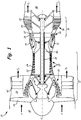
- FIG. 1 is a cross-sectional view of gas turbine engine 10.
- Gas turbine engine (or turbine engine) 10 includes a power core with compressor section 12, combustor 14 and turbine section 16 arranged in flow series between upstream inlet 18 and downstream exhaust 20.
- Compressor section 12 and turbine section 16 are arranged into a number of alternating stages of rotor airfoils (or blades) 22 and stator airfoils (or vanes) 24.
- propulsion fan 26 is positioned in bypass duct 28, which is coaxially oriented about the engine core along centerline (or turbine axis) C L .
- An open-rotor propulsion stage 26 may also provided, with turbine engine 10 operating as a turboprop or unducted turbofan engine.
- fan rotor 26 and bypass duct 28 may be absent, with turbine engine 10 configured as a turbojet or turboshaft engine, or an industrial gas turbine.
- components of gas turbine engine 10 are provided with an improved cooling configuration, as described below.
- Suitable components for the cooling configuration include rotor airfoils 22, stator airfoils 24 and other gas turbine engine components exposed to hot gas flow, including, but not limited to, platforms, shrouds, casings and other endwall surfaces in hot sections of compressor 12 and turbine 16, and liners, nozzles, afterburners, augmentors and other gas wall components in combustor 14 and exhaust section 20.
- compressor section 12 includes low pressure compressor (LPC) 30 and high pressure compressor (HPC) 32, and turbine section 16 includes high pressure turbine (HPT) 34 and low pressure turbine (LPT) 36.
- Low pressure compressor 30 is rotationally coupled to low pressure turbine 36 via low pressure (LP) shaft 38, forming the LP spool or low spool.
- High pressure compressor 32 is rotationally coupled to high pressure turbine 34 via high pressure (HP) shaft 40, forming the HP spool or high spool.
- Flow F at inlet 18 divides into primary (core) flow Fp and secondary (bypass) flow F S downstream of fan rotor 26.
- Fan rotor 26 accelerates secondary flow F S through bypass duct 28, with fan exit guide vanes (FEGVs) 42 to reduce swirl and improve thrust performance.
- FEGVs fan exit guide vanes
- structural guide vanes (SGVs) 42 are used, providing combined flow turning and load bearing capabilities.
- Primary flow F P is compressed in low pressure compressor 30 and high pressure compressor 32, then mixed with fuel in combustor 14 and ignited to generate hot combustion gas.
- the combustion gas expands to provide rotational energy in high pressure turbine 34 and low pressure turbine 36, driving high pressure compressor 32 and low pressure compressor 30, respectively.
- Expanded combustion gases exit through exhaust section (or exhaust nozzle) 20, which can be shaped or actuated to regulate the exhaust flow and improve thrust performance.
- Low pressure shaft 38 and high pressure shaft 40 are mounted coaxially about centerline C L , and rotate at different speeds.
- Fan rotor (or other propulsion stage) 26 is rotationally coupled to low pressure shaft 38.
- fan drive gear system 44 is provided for additional fan speed control, improving thrust performance and efficiency with reduced noise output.
- Fan rotor 26 may also function as a first-stage compressor for gas turbine engine 10, and LPC 30 may be configured as an intermediate compressor or booster.
- propulsion stage 26 has an open rotor design, or is absent, as described above.
- Gas turbine engine 10 thus encompasses a wide range of different shaft, spool and turbine engine configurations, including one, two and three-spool turboprop and (high or low bypass) turbofan engines, turboshaft engines, turbojet engines, and multi-spool industrial gas turbines.
- turbine efficiency and performance depend on the overall pressure ratio, defined by the total pressure at inlet 18 as compared to the exit pressure of compressor section 12, for example at the outlet of high pressure compressor 32, entering combustor 14. Higher pressure ratios, however, also result in greater gas path temperatures, increasing the cooling loads on rotor airfoils 22, stator airfoils 24 and other components of gas turbine engine 10. To reduce operating temperatures, increase service life and maintain engine efficiency, these components are provided with improved cooling configurations, as described below. Suitable components include, but are not limited to, cooled gas turbine engine components in compressor sections 30 and 32, combustor 14, turbine sections 34 and 36, and exhaust section 20 of gas turbine engine 10.
- FIG. 2A is a perspective view of rotor airfoil (or blade) 22 for gas turbine engine 10, as shown in FIG. 1 , or for another turbomachine.
- Rotor airfoil 22 extends axially from leading edge 51 to trailing edge 52, defining pressure surface 53 (front) and suction surface 54 (back) therebetween.
- Pressure and suction surfaces 53 and 54 form the major opposing surfaces or walls of airfoil 22, extending axially between leading edge 51 and trailing edge 52, and radially from root section 55, adjacent inner diameter (ID) platform 56, to tip section 57, opposite ID platform 56.
- tip section 57 is shrouded.
- Cooling holes or outlets 60 are provided on one or more surfaces of airfoil 22, for example along leading edge 51, trailing edge 52, pressure (or concave) surface 53, or suction (or convex) surface 54, or a combination thereof. Cooling holes or passages 60 may also be provided on the endwall surfaces of airfoil 22, for example along ID platform 56, or on a shroud or engine casing adjacent tip section 57.
- FIG. 2B is a perspective view of stator airfoil (or vane) 24 for gas turbine engine 10, as shown in FIG. 1 , or for another turbomachine.
- Stator airfoil 24 extends axially from leading edge 61 to trailing edge 62, defining pressure surface 63 (front) and suction surface 64 (back) therebetween.
- Pressure and suction surfaces 63 and 64 extend from inner (or root) section 65, adjacent ID platform 66, to outer (or tip) section 67, adjacent outer diameter (OD) platform 68.
- Cooling holes or outlets 60 are provided along one or more surfaces of airfoil 24, for example leading or trailing edge 61 or 62, pressure (concave) or suction (convex) surface 63 or 64, or a combination thereof. Cooling holes or passages 60 may also be provided on the endwall surfaces of airfoil 24, for example along ID platform 66 and OD platform 68.
- Rotor airfoils 22 ( FIG. 2A ) and stator airfoils 24 ( FIG. 2B ) are formed of high strength, heat resistant materials such as high temperature alloys and superalloys, and are provided with thermal and erosion-resistant coatings.
- Airfoils 22 and 24 are also provided with internal cooling passages and cooling holes 60 to reduce thermal fatigue and wear, and to prevent melting when exposed to hot gas flow in the higher temperature regions of a gas turbine engine or other turbomachine.
- Cooling holes 60 deliver cooling fluid (e.g., steam or air from a compressor) through the outer walls and platform structures of airfoils 22 and 24, creating a thin layer (or film) of cooling fluid to protect the outer (gas path) surfaces from high temperature flow.
- cooling fluid e.g., steam or air from a compressor
- Cooling holes 60 are thus provided with improved metering and inlet geometry to reduce jets and blow off, and improved diffusion and exit geometry to reduce flow separation and corner effects. Cooling holes 60 reduce flow requirements and improve the spread of cooling fluid across the hot outer surfaces of airfoils 22 and 24, and other gas turbine engine components, so that less flow is needed for cooling and efficiency is maintained or increased.
- multi-lobed cooling holes described herein provide a cooling solution that offers improved film cooling coverage and eliminates or reduces the problems associated with conventional diffusion film cooling holes, such as flow separation and blow off. Additionally, multi-lobed cooling holes can be manufactured at a lower cost than other cooling holes having unique geometries. These features present a cooling hole that offers improvements over the state of the art. Multi-lobed cooling holes provide improved film effectiveness and reduce the likelihood of film separation so that they work as intended at high blowing ratios and reduce the detrimental effects such as kidney vortices.
- FIG. 3 illustrates a view of a wall having multi-lobed film cooling holes.
- Wall 100 includes inner wall surface 102 and outer wall surface 104. As described in greater detail below, wall 100 is metallic and outer wall surface 104 can include coating layers such as a thermal barrier coating or a bonding layer.
- Multi-lobed film cooling holes 106 are oriented so that their inlets are positioned on the first wall surface 102 and their outlets are positioned on outer wall surface 104.
- outer wall surface 104 is in proximity to high temperature gases (e.g., combustion gases, hot air). Cooling air is delivered inside wall 100 where it exits the interior of the component through cooling holes 106 and forms a cooling film on outer wall surface 104.
- cooling holes 106 have two lobes in the diffusing section of the cooling hole.
- cooling air flows out of cooling holes 106 and flows through each of the lobes in the diffusing section.
- Cooling holes 106 can be arranged in a linear row on wall 100 as shown in FIG. 3 and positioned axially so that the cooling air flows in substantially the same direction longitudinally as the high temperature gases flowing past wall 100.
- cooling air passing through cooling holes 106 exits cooling holes traveling in substantially the same direction as the high temperature gases flowing along outer wall surface 104 (represented by arrow H).
- the row of cooling holes 106 is substantially perpendicular to the direction of flow H.
- cooling holes 106 can be arranged on outer wall surface 104 so that the flow of cooling air is substantially perpendicular to the high temperature gas flow (i.e. cooling air exits cooling holes 106 radially) or at an angle between parallel and perpendicular. Cooling holes 106 can also be provided in a staggered formation or other formation on wall 100. Cooling holes 106 can be located on a variety of components that require cooling. Suitable components include, but are not limited to, turbine vanes and blades, combustors, blade outer air seals, and augmentors, etc. Cooling holes 106 can be located on the pressure side or suction side of vanes and blades. Cooling holes 106 can also be located on the blade tip or blade or vane platforms.
- FIGs. 4, 5 and 6 illustrate one embodiment of cooling hole 106 in greater detail.
- FIG. 4 illustrates a sectional view of multi-lobed film cooling hole 106 of FIG. 3 taken along the line 4-4.
- Cooling hole 106 includes inlet 110, metering section 112, diffusing section 114 and outlet 116.
- Inlet 110 is an opening located on inner wall surface 102. Cooling air C enters cooling hole 106 through inlet 110 and passes through metering section 112 and diffusing section 114 before exiting cooling hole 106 at outlet 116 along outer wall surface 104.
- Metering section 112 is adjacent to and downstream from inlet 110 and controls (meters) the flow of air through cooling hole 106.
- metering section 112 has a substantially constant flow area from inlet 110 to diffusing section 114.
- Metering section 112 can have circular, oblong (oval or elliptical), racetrack (oval with two parallel sides having straight portions) or crescent shaped cross sections.
- metering section 112 has a circular cross section.
- Circular metering sections 112 have a length l and diameter d (hydraulic diameter d h where metering section 112 is non-circular).
- inlet 110 and metering section 112 have the same diameter d .
- circular metering section 112 has a length l according to the relationship: d ⁇ l ⁇ 3 d. That is, the length of metering section 112 is between one and three times its diameter. The length of metering section 112 can exceed 3 d , reaching upwards of 30 d .
- metering section 112 has an oblong or racetrack-shaped cross section. As oblong and racetrack configurations are not circular, their metering sections 112 have a length l and hydraulic diameter d h . In some embodiments, metering section 112 has a length l according to the relationship: d h ⁇ l ⁇ 3 d h .
- the length of metering section 112 is between one and three times its hydraulic diameter. Again, the length of metering section 112 can exceed 3 d h , reaching upwards of 30 d h .
- metering section 112 is inclined with respect to wall 100 as illustrated in FIG. 4 (i.e. metering section 112 is not perpendicular to wall 100).
- Metering section 112 has a longitudinal axis represented by numeral 118. Longitudinal axis 118 represents the angle of metering section 112 between first wall surface 102 and second wall surface 104.
- Diffusing section 114 is adjacent to and downstream from metering section 112. Cooling air C diffuses within diffusing section 114 before exiting cooling hole 106 along outer wall surface 104. Outer wall surface 104 includes upstream end 120 (upstream of cooling hole 106) and downstream end 122 (downstream from cooling hole 106). Diffusing section 114 opens along outer wall surface 104 between upstream end 120 and downstream end 122. As shown in FIG. 4 , cooling air C diffuses in diffusing section 114 as it flows towards outlet 116.
- diffusing section 114 includes two channel-like lobes 124 and 126.
- Each lobe 124, 126 diverges longitudinally and laterally from metering section 112 and has a bottom surface (bottom surfaces 128 and 130, respectively), a side wall along the outer edge of diffusing section 114 (the side walls are represented by lines 132 and 134, respectively) and a trailing edge (trailing edges 136 and 138, respectively).
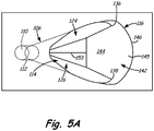
- FIG. 4 best illustrates the longitudinal divergence (from longitudinal axis 118), while FIG. 5 best illustrates the lateral divergence (from centerline axis 140, an axis extending through the center of metering section 112).
- FIG. 4 best illustrates the longitudinal divergence (from longitudinal axis 118)
- FIG. 5 best illustrates the lateral divergence (from centerline axis 140, an axis extending through the center of metering section 112).
- first lobe 124 laterally diverges upwards from centerline axis 140 and second lobe 126 laterally diverges downwards from centerline axis 140.
- Cooling air C leaving metering section 112 and entering diffusing section 114 diffuses into lobes 124 and 126, causing the cooling air to spread laterally within diffusing section 114.
- Side wall 132 and bottom surface 128 direct cooling air C through first lobe 124, and side wall 134 and bottom surface 130 direct cooling air C through second lobe 126.
- bottom surface 130 can be inclined with respect to outer wall surface 104 as shown by inclination angle A.
- Diffusing section 114 also includes interlobe or transition region 142.
- Portion 144 of transition region 142 is located between first lobe 124 and second lobe 126. In some embodiments, a portion of transition region 142 extends beyond lobes 124 and 126 and that portion is no longer "between" the lobes.
- End 146 of transition region 142 is adjacent outlet 116 where the outlet meets outer wall surface 104.
- Portion 144, located between first lobe 124 and second lobe 126 can extend towards metering section 112 to varying degrees. In the embodiment shown in FIG. 5 , portion 144 is present only near the respective trailing edges 136 and 138 of lobes 124 and 126.
- end 146 of transition region 142 can also vary. In the embodiment shown in FIG. 5 , end 146 is spaced from trailing edges 136 and 138. In this embodiment, trailing edges 136 and 138 and hence, first lobe 124 and second lobe 126, do not extend to outlet 116 or outer wall surface 104. Portion 145 of transition region 142 is located between trailing edges 136 and 138 and outlet 116. In some exemplary embodiments, transition region 142 spans trailing edge 136 and trailing edge 138 as shown in FIG. 5 .
- Transition region 142 (and portions 144 and 145) can take various shapes and have different configurations depending on the location and desired flow profile of cooling hole 106.
- the bottom surface of transition region 142 can be flat or curved.
- transition region 142 can be longitudinally convex, laterally convex, both longitudinally and laterally convex, concave or have other shapes.
- a curved (for example, longitudinally convex) bottom surface of transition region 142 can facilitate improved flow attachment due to the Coanda effect.
- End 146 can also be curved, instead of straight, as shown in FIG. 5A .
- diffusing section 114 also includes first inclined portion 148 and second inclined portion 150.
- First inclined portion 148 is located adjacent to and extends from bottom surface 128 of first lobe 124.
- First inclined portion 148 extends from first lobe 124 towards centerline axis 140 and second lobe 126.
- Second inclined portion 150 is located adjacent to and extends from bottom surface 130 of second lobe 126.
- Second inclined portion 150 extends from second lobe 126 towards centerline axis 140 and first lobe 124.
- first inclined portion 148 and second inclined portion 150 can have varying lateral and longitudinal lengths and extend from lobes 124 and 126 at various angles (inclinations).
- first and second inclined portions 148 and 150 direct cooling air C through lobes 124 and 126 of diffusing section 114.
- First and second inclined portions 148 and 150 can be planar or curved.
- first inclined portion 148 and second inclined portion 150 meet together to form a ridge as shown in FIG. 5 .
- Ridge 152 is located between first lobe 124 and second lobe 126 at the intersection of first inclined portion 148 and second inclined portion 150. Ridge 152 aids in separating and directing the flow of cooling air C into first lobe 124 and second lobe 126.
- the location and angle of ridge 152 within diffusing section 114 can vary to direct cooling air C within diffusing section 114 to suit the location and desired flow profile of cooling hole 106. As shown in FIG. 5 , ridge 152 is coincident with centerline axis 140 (i.e. centerline axis 140 lies atop ridge 152).
- the location of ridge 152 can be shifted towards side wall 132 or side wall 134 instead of following centerline axis 140.
- Corresponding changes to the lateral lengths and/or angles of first inclined portion 148 and second inclined portion 150 must accompany any change in the location of ridge 152.
- Ridge 152 can also be inclined relative to centerline axis 140 instead of being parallel. Ridge 152 can be angled so that a downstream portion of ridge 152 is closer to one side wall than the other.
- corresponding changes to the lateral lengths and/or angles of first inclined portion 148 and second inclined portion 150 must accompany any change in the angle of ridge 152.
- Ridge 152 can extend longitudinally to varying degrees between metering section 112 and transition region 142. Ridge 152 can extend upstream all the way to metering section 112, beginning where metering section 112 and diffusing section 114 meet as shown in FIG. 4 . Alternatively, ridge 152 can begin farther downstream (closer to outlet 116). Ridge 152 can extend downstream to transition region 142 as shown in FIG. 4 . Alternatively, ridge 152 can converge with bottom surfaces 128 and 130 upstream of transition region 142. Corresponding changes to the longitudinal lengths of first inclined portion 148 and second inclined portion 150 must accompany any change in the longitudinal extension of ridge 152. As shown best in FIG.
- ridge 152 can be inclined with respect to outer wall surface 104 as shown by inclination angle B. Also, as shown in FIG. 4 , ridge 152 does not extend to outlet 116. At point 153, ridge 152 begins to converge towards bottom surfaces 128 and 130 so that no ridge is present in transition region 142.
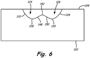
- FIG. 6 illustrates a lateral cross-section view of the embodiment of cooling hole 106 shown in FIGs. 4 and 5 . The height of ridge 152 with respect to bottom surfaces 128 and 130 can vary. Ridge 152 can also be rounded to a greater a degree than shown in FIG. 6 .
- transition region 142 to diffusing section 114 improves the thermo-mechanical fatigue tolerance of multi-lobed film cooling hole 106.
- the trailing edge of cooling hole 106 (where outlet 116 and outer wall surface 104 meet) would include sharp edges or corners at the trailing edge of ridge 152 and at trailing edges 136 and 138 of lobes 124 and 126. These sharp edges and corners are highly susceptible to thermo-mechanical fatigue. Over time, cracks develop in these areas due to the temperature cycling that occurs during operation. These cracks further reduce cooling effectiveness and performance and will eventually lead to failure, requiring repair or replacement of the affected component. Repairing and replacing components is costly both in terms of materials and in aircraft downtime.
- transition region 142 By incorporating transition region 142 to diffusing section 114, the previously sharp edges and corners are blended into smoother transitions that are less susceptible to thermo-mechanical fatigue. Additionally, the smoother transitions near ridge 152 and trailing edges 136 and 138 reduces the likelihood that cooling air C will "jet off' instead of forming a cooling film along outer wall surface 104.
- transition region 142 has a generally trapezoidal shape.
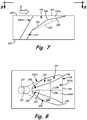
- FIGs. 7 and 8 illustrate another embodiment of a multi-lobed film cooling hole in greater detail.
- FIG. 7 illustrates a sectional view of cooling hole 106A
- FIG. 8 illustrates a plane view.
- first lobe 124 and second lobe 126 extend to outlet 116 at outer wall surface 104.
- Transition region 142A includes only first portion 144A as no portion of transition region 142A extends between respective trailing edges 136 and 138 of lobes 124 and 126 and outlet 116.
- Transition region 142A has a trapezoidal shape and extends towards metering section 112 farther than the embodiment shown in FIGs. 4-6 .
- Transition region 142A has a compound trapezoidal shape as ridge 154 separates transition region 142A into two sides, each having a separate surface. Each surface of transition region 142A can be flat or curved. Curved surfaces can be convex longitudinally, laterally or both longitudinally and laterally. In alternate embodiments, ridge 154 is absent from transition region 142A and transition region 142A is a flat trapezoidal surface extending between first lobe 124 and second lobe 126. Diffusing section 114 includes first inclined portion 148, second inclined portion 150 and ridge 152. In this embodiment, transition region 142A includes ridge 154 laterally bisecting transition region 142A.
- Ridge 154 longitudinally aligns with bottom surface 130 of second lobe 126 at outlet 116 at outer wall surface 104 as shown in FIG. 7 .
- the intersection of ridges 152 and 154 at the point where transition region 142A meets first inclined portion 148 and second inclined portion 150 forms apex 156.
- diffusing section 114 facilitates improved flow attachment due to the Coanda effect.
- the location and shape of transition region 142A can vary so that the location of apex 156 varies between metering section 112 and outlet 116.
- FIGs. 9 and 10 illustrate another embodiment of a multi-lobed film cooling hole in greater detail.
- FIG. 9 illustrates a sectional view of cooling hole 106B
- FIG. 10 illustrates a plane view.
- central portion 158 is located between lobes 124 and 126.
- Central portion 158 can be flush with bottom surfaces 128 and 130 of lobes 124 and 126, respectively.
- central portion 158 can be a raised surface (flat or curved) between first lobe 124 and second lobe 126.
- Central portion 158 can be flat or curved (convex or concave) in the longitudinal or lateral direction.
- Transition region 142 can include ridge 154 (as shown in FIGs. 9 and 10 ) or ridge 154 can be omitted. Transition regions 142 having ridge 154 can also include apex 155 such that the trailing edge of ridge 154 longitudinally aligns with bottom surfaces 128 and 130 at outlet 116. The location and shape of transition region 142 can vary so that the location of apex 155 varies between central portion 158 and outlet 116.
- central portion 158 can vary. Central portion 158 increases the geometric coverage of cooling air C within diffusing section 114, thereby increasing the film effectiveness of cooling air C flowing out of outlet 116. Whether central portion 158 is flat or curved can depend upon the local velocity of cooling air C and the blowing ratio of cooling hole 106. For example, at blowing ratios above about 2, central portion 158 can be small and provide a small degree of diffusion. At lower blowing ratios (less than about 0.5), central portion can be larger and allow for a greater degree of diffusion.
- cooling hole 106 does not contain ridges or ribs in portion 145 of transition region 142.
- portion 145 of transition region 142 includes one or more ridges or ribs.
- FIG. 11A illustrates one embodiment of a multi-lobed film cooling hole in which portion 145 of transition region 142 includes a ridge.
- FIG. 11A illustrates a plane view of cooling hole 106C. Cooling hole 106C is similar to cooling hole 106 illustrated in FIG. 5 . However, ridge 152 extends from diffusing section 114 through transition region 142. Ridge 152 extends substantially along centerline axis 140 through portions 144 and 145 of transition region 142, all the way to end 146.
- ridge 152 does not extend all the way to end 146, but transitions (tapers) towards the bottom surface of transition region 142 in portion 144 or 145. Ridge 152 in transition region 142 can also increase or decrease in relative height as it proceeds downstream through transition region 142. Ridge 162 can be longitudinally and/or laterally straight or curved.
- ridge 152 does not extend into transition region 142. Instead, rib 160 is formed in transition region 142 as shown in cooling hole 106D of FIG. 11B . In some embodiments, rib 160 is parallel to and aligned with ridge 152. In other embodiments, multiple ribs 160 are present in transition region 142. Extending ridge 152 into transition region 142 or adding rib 160 to transition region 142 helps to channel the flow of cooling air C and prevent it from separating downstream of lobes 124 and 126, reducing the likelihood of flow separation.
- bottom surfaces 128 and 130, side walls 132 and 134, inclined portions 148 and 150 and transition region 142 can also contain anti-vortex features to prevent the formation of kidney vortices and subsequent hot gas entrainment at outlet 116.
- gas turbine engine components, gas path walls and cooling passages described herein can thus be manufactured using one or more of a variety of different processes. These techniques provide each cooling hole and cooling passage with its own particular configuration and features, including, but not limited to, inlet, metering, transition, diffusion, outlet, upstream wall, downstream wall, lateral wall, lobe and downstream edge features, as described above. In some cases, multiple techniques can be combined to improve overall cooling performance or reproducibility, or to reduce manufacturing costs.
- Suitable manufacturing techniques for forming the cooling configurations described here include, but are not limited to, electrical discharge machining (EDM), laser drilling, laser machining, electrical chemical machining (ECM), water jet machining, casting, conventional machining and combinations thereof.
- Electrical discharge machining includes both machining using a shaped electrode as well as multiple pass methods using a hollow spindle or similar electrode component.
- Laser machining methods include, but are not limited to, material removal by ablation, trepanning and percussion laser machining.
- Conventional machining methods include, but are not limited to, milling, drilling and grinding.
- the gas flow path walls and outer surfaces of some gas turbine engine components include one or more coatings, such as bond coats, thermal barrier coatings, abrasive coatings, abradable coatings and erosion or erosion-resistant coatings.
- coatings such as bond coats, thermal barrier coatings, abrasive coatings, abradable coatings and erosion or erosion-resistant coatings.
- the inlet, metering portion, transition, diffusion portion and outlet cooling features may be formed prior to coating application, after a first coating (e.g., a bond coat) is applied, or after a second or third (e.g., interlayer) coating process, or a final coating (e.g., environmental or thermal barrier) coating process.
- the diffusion portion and outlet features may be located within a wall or substrate, within a thermal barrier coating or other coating layer applied to a wall or substrate, or based on combinations thereof.
- the cooling geometry and other features may remain as described above, regardless of position relative to the wall and coating materials or airfoil materials.
- cooling features may affect selection of manufacturing techniques, including techniques used in forming the inlet, metering portion, transition, outlet, diffusion portion and other cooling features.
- a thermal barrier coat or other coating is applied to the outer surface of a gas path wall before the cooling hole or passage is produced.
- laser ablation or laser drilling may be used.
- either laser drilling or water jet machining may be used on a surface without a thermal barrier coat.
- different machining methods may be more or less suitable for forming different features of the cooling hole or cooling passage, for example, different EDM, laser machining and other machining techniques may be used for forming the outlet and diffusion features, and for forming the transition, metering and inlet features.
- FIG. 12A is a simplified flow diagram illustrating one embodiment of a method for producing a multi-lobed cooling hole in a gas turbine engine wall having inner and outer surfaces.
- Method 200 includes forming a metering section between the inner and outer surfaces (step 202) and forming a diffusing section between the metering section and the outer surface (step 204).
- Metering section 112 is formed in step 202 by one or more of the casting, machining or drilling techniques described above. The technique(s) chosen is/are typically determined based on performance, reproducibility and cost.
- inlet 110 and portions of diffusing section 114 and outlet 116 can also be formed during formation of metering section 112.
- Diffusing section 114 is formed in step 204 by one or more of the casting, machining or drilling techniques described above. As with metering section 112, the technique(s) chosen is/are typically determined based on performance, reproducibility and cost. In embodiments where step 202 occurs prior to step 204, outlet 116 is fully formed during step 204. Steps 202 and 204 can be performed before or after an optional thermal barrier coating application. In optional step 206 (shown as a step in method 200A in FIG. 12B ), a thermal barrier coating is applied to outer wall surface 104. Application of the thermal barrier coating can also include the application of a bond coating prior to the thermal barrier coating.
- Steps 202, 204 and step 206 can be performed in any order depending on the location of cooling hole 106 and the location of diffusing section 114 relative to the metallic wall and the thermal barrier coating. As previously stated, the order of steps 202, 204 and step 206 can affect the machining or drilling techniques chosen for steps 202 and 204.
Description
- This invention relates generally to turbomachinery, and specifically to turbine flow path components for gas turbine engines. In particular, the invention relates to cooling techniques for airfoils and other gas turbine engine components exposed to hot working fluid flow, including, but not limited to, rotor blades and stator vane airfoils, endwall surfaces including platforms, shrouds and compressor and turbine casings, combustor liners, turbine exhaust assemblies, thrust augmentors and exhaust nozzles.
- Gas turbine engines are rotary-type combustion turbine engines built around a power core made up of a compressor, combustor and turbine, arranged in flow series with an upstream inlet and downstream exhaust. The compressor section compresses air from the inlet, which is mixed with fuel in the combustor and ignited to generate hot combustion gas. The turbine section extracts energy from the expanding combustion gas, and drives the compressor section via a common shaft. Expanded combustion products are exhausted downstream, and energy is delivered in the form of rotational energy in the shaft, reactive thrust from the exhaust, or both.
- Gas turbine engines provide efficient, reliable power for a wide range of applications in aviation, transportation and industrial power generation. Small-scale gas turbine engines typically utilize a one-spool design, with co-rotating compressor and turbine sections. Larger-scale combustion turbines including jet engines and industrial gas turbines (IGTs) are generally arranged into a number of coaxially nested spools. The spools operate at different pressures, temperatures and spool speeds, and may rotate in different directions.
- Individual compressor and turbine sections in each spool may also be subdivided into a number of stages, formed of alternating rows of rotor blade and stator vane airfoils. The airfoils are shaped to turn, accelerate and compress the working fluid flow, or to generate lift for conversion to rotational energy in the turbine.
- Industrial gas turbines often utilize complex nested spool configurations, and deliver power via an output shaft coupled to an electrical generator or other load, typically using an external gearbox. In combined cycle gas turbines (CCGTs), a steam turbine or other secondary system is used to extract additional energy from the exhaust, improving thermodynamic efficiency. Gas turbine engines are also used in marine and land-based applications, including naval vessels, trains and armored vehicles, and in smaller-scale applications such as auxiliary power units.
- Aviation applications include turbojet, turbofan, turboprop and turboshaft engine designs. In turbojet engines, thrust is generated primarily from the exhaust. Modern fixed-wing aircraft generally employ turbofan and turboprop configurations, in which the low pressure spool is coupled to a propulsion fan or propeller. Turboshaft engines are employed on rotary-wing aircraft, including helicopters, typically using a reduction gearbox to control blade speed. Unducted (open rotor) turbofans and ducted propeller engines also known, in a variety of single-rotor and contra-rotating designs with both forward and aft mounting configurations.
- Aviation turbines generally utilize two and three-spool configurations, with a corresponding number of coaxially rotating turbine and compressor sections. In two-spool designs, the high pressure turbine drives a high pressure compressor, forming the high pressure spool or high spool. The low-pressure turbine drives the low spool and fan section, or a shaft for a rotor or propeller. In three-spool engines, there is also an intermediate pressure spool. Aviation turbines are also used to power auxiliary devices including electrical generators, hydraulic pumps and elements of the environmental control system, for example using bleed air from the compressor or via an accessory gearbox.
- Additional turbine engine applications and turbine engine types include intercooled, regenerated or recuperated and variable cycle gas turbine engines, and combinations thereof. In particular, these applications include intercooled turbine engines, for example with a relatively higher pressure ratio, regenerated or recuperated gas turbine engines, for example with a relatively lower pressure ratio or for smaller-scale applications, and variable cycle gas turbine engines, for example for operation under a range of flight conditions including subsonic, transonic and supersonic speeds. Combined intercooled and regenerated/recuperated engines are also known, in a variety of spool configurations with traditional and variable cycle modes of operation.
- Turbofan engines are commonly divided into high and low bypass configurations. High bypass turbofans generate thrust primarily from the fan, which accelerates airflow through a bypass duct oriented around the engine core. This design is common on commercial aircraft and transports, where noise and fuel efficiency are primary concerns. The fan rotor may also operate as a first stage compressor, or as a pre-compressor stage for the low-pressure compressor or booster module. Variable-area nozzle surfaces can also be deployed to regulate the bypass pressure and improve fan performance, for example during takeoff and landing. Advanced turbofan engines may also utilize a geared fan drive mechanism to provide greater speed control, reducing noise and increasing engine efficiency, or to increase or decrease specific thrust.
- Low bypass turbofans produce proportionally more thrust from the exhaust flow, generating greater specific thrust for use in high-performance applications including supersonic jet aircraft. Low bypass turbofan engines may also include variable-area exhaust nozzles and afterburner or augmentor assemblies for flow regulation and short-term thrust enhancement. Specialized high-speed applications include continuously afterburning engines and hybrid turbojet/ramjet configurations.
- Across these applications, turbine performance depends on the balance between higher pressure ratios and core gas path temperatures, which tend to increase efficiency, and the related effects on service life and reliability due to increased stress and wear. This balance is particularly relevant to gas turbine engine components in the hot sections of the compressor, combustor, turbine and exhaust sections, where active cooling is required to prevent damage due to high gas path temperatures and pressures.
US8057181 B1 describes a multiple expansion film cooling hole for a turbine airfoil.US7997868 B1 describes a turbine airfoil with a film cooling hole having a bell mouth shaped opening.EP2083147 A1 describes a film cooling structure.US 2010/0068068 A1 describes a turbine airfoil cooling system with a diffusion film cooling hole having a flow restriction rib.JP 2008248733 EP 1609949 A1 describes a film cooled wall with chevron shaped cooling holes.EP 1967696 A1 describes a turbine component comprising a plurality of cooling holes. - The invention is defined in the accompanying claims.
-
-
FIG. 1 is a cross-sectional view of a gas turbine engine. -
FIG. 2A is a perspective view of an airfoil for the gas turbine engine, in a rotor blade configuration. -
FIG. 2B is a perspective view of an airfoil for the gas turbine engine, in a stator vane configuration. -
FIG. 3 illustrates a wall having multi-lobed cooling holes. -
FIG. 4 is a sectional view through one embodiment of a multi-lobed cooling hole.FIG. 5 is a view of the multi-lobed cooling hole illustrated inFIG. 4 and taken along the line 5-5. -
FIG. 5A is a view of another embodiment of a multi-lobed cooling hole. -
FIG. 6 is a sectional view through the multi-lobed cooling hole illustrated inFIG. 5 and taken along the line 6-6. -
FIG. 7 is a sectional view through another embodiment of a multi-lobed cooling hole. -
FIG. 8 is a view of the multi-lobed cooling hole illustrated inFIG. 7 and taken along the line 8-8. -
FIG. 9 is a sectional view through another embodiment of a multi-lobed cooling hole. -
FIG. 10 is a view of the multi-lobed cooling hole illustrated inFIG. 9 and taken along the line 10-10. -
FIG. 11A is a view of another embodiment of a multi-lobed cooling hole. -
FIG. 11B is a view of another embodiment of a multi-lobed cooling hole. -
FIG. 12A is a simplified flow diagram illustrating one embodiment of a method for producing a cooling hole in a gas turbine engine wall. -
FIG. 12B is a simplified flow diagram illustrating another embodiment of a method for producing a cooling hole in a gas turbine engine wall. -
FIG. 1 is a cross-sectional view ofgas turbine engine 10. Gas turbine engine (or turbine engine) 10 includes a power core withcompressor section 12,combustor 14 andturbine section 16 arranged in flow series betweenupstream inlet 18 anddownstream exhaust 20.Compressor section 12 andturbine section 16 are arranged into a number of alternating stages of rotor airfoils (or blades) 22 and stator airfoils (or vanes) 24. - In the turbofan configuration of
FIG. 1 ,propulsion fan 26 is positioned inbypass duct 28, which is coaxially oriented about the engine core along centerline (or turbine axis) CL. An open-rotor propulsion stage 26 may also provided, withturbine engine 10 operating as a turboprop or unducted turbofan engine. Alternatively,fan rotor 26 andbypass duct 28 may be absent, withturbine engine 10 configured as a turbojet or turboshaft engine, or an industrial gas turbine. - For improved service life and reliability, components of
gas turbine engine 10 are provided with an improved cooling configuration, as described below. Suitable components for the cooling configuration includerotor airfoils 22,stator airfoils 24 and other gas turbine engine components exposed to hot gas flow, including, but not limited to, platforms, shrouds, casings and other endwall surfaces in hot sections ofcompressor 12 andturbine 16, and liners, nozzles, afterburners, augmentors and other gas wall components incombustor 14 andexhaust section 20. - In the two-spool, high bypass configuration of
FIG. 1 ,compressor section 12 includes low pressure compressor (LPC) 30 and high pressure compressor (HPC) 32, andturbine section 16 includes high pressure turbine (HPT) 34 and low pressure turbine (LPT) 36.Low pressure compressor 30 is rotationally coupled tolow pressure turbine 36 via low pressure (LP)shaft 38, forming the LP spool or low spool.High pressure compressor 32 is rotationally coupled tohigh pressure turbine 34 via high pressure (HP)shaft 40, forming the HP spool or high spool. - Flow F at
inlet 18 divides into primary (core) flow Fp and secondary (bypass) flow FS downstream offan rotor 26.Fan rotor 26 accelerates secondary flow FS throughbypass duct 28, with fan exit guide vanes (FEGVs) 42 to reduce swirl and improve thrust performance. In some designs, structural guide vanes (SGVs) 42 are used, providing combined flow turning and load bearing capabilities. - Primary flow FP is compressed in
low pressure compressor 30 andhigh pressure compressor 32, then mixed with fuel incombustor 14 and ignited to generate hot combustion gas. The combustion gas expands to provide rotational energy inhigh pressure turbine 34 andlow pressure turbine 36, drivinghigh pressure compressor 32 andlow pressure compressor 30, respectively. Expanded combustion gases exit through exhaust section (or exhaust nozzle) 20, which can be shaped or actuated to regulate the exhaust flow and improve thrust performance. -
Low pressure shaft 38 andhigh pressure shaft 40 are mounted coaxially about centerline CL, and rotate at different speeds. Fan rotor (or other propulsion stage) 26 is rotationally coupled tolow pressure shaft 38. In advanced designs, fandrive gear system 44 is provided for additional fan speed control, improving thrust performance and efficiency with reduced noise output. -
Fan rotor 26 may also function as a first-stage compressor forgas turbine engine 10, andLPC 30 may be configured as an intermediate compressor or booster. Alternatively,propulsion stage 26 has an open rotor design, or is absent, as described above.Gas turbine engine 10 thus encompasses a wide range of different shaft, spool and turbine engine configurations, including one, two and three-spool turboprop and (high or low bypass) turbofan engines, turboshaft engines, turbojet engines, and multi-spool industrial gas turbines. - In each of these applications, turbine efficiency and performance depend on the overall pressure ratio, defined by the total pressure at
inlet 18 as compared to the exit pressure ofcompressor section 12, for example at the outlet ofhigh pressure compressor 32, enteringcombustor 14. Higher pressure ratios, however, also result in greater gas path temperatures, increasing the cooling loads onrotor airfoils 22,stator airfoils 24 and other components ofgas turbine engine 10. To reduce operating temperatures, increase service life and maintain engine efficiency, these components are provided with improved cooling configurations, as described below. Suitable components include, but are not limited to, cooled gas turbine engine components incompressor sections combustor 14,turbine sections exhaust section 20 ofgas turbine engine 10. -
FIG. 2A is a perspective view of rotor airfoil (or blade) 22 forgas turbine engine 10, as shown inFIG. 1 , or for another turbomachine.Rotor airfoil 22 extends axially from leadingedge 51 to trailingedge 52, defining pressure surface 53 (front) and suction surface 54 (back) therebetween. - Pressure and suction surfaces 53 and 54 form the major opposing surfaces or walls of
airfoil 22, extending axially between leadingedge 51 and trailingedge 52, and radially fromroot section 55, adjacent inner diameter (ID)platform 56, to tipsection 57,opposite ID platform 56. In some designs,tip section 57 is shrouded. - Cooling holes or
outlets 60 are provided on one or more surfaces ofairfoil 22, for example along leadingedge 51, trailingedge 52, pressure (or concave)surface 53, or suction (or convex)surface 54, or a combination thereof. Cooling holes orpassages 60 may also be provided on the endwall surfaces ofairfoil 22, for example alongID platform 56, or on a shroud or engine casingadjacent tip section 57. -
FIG. 2B is a perspective view of stator airfoil (or vane) 24 forgas turbine engine 10, as shown inFIG. 1 , or for another turbomachine.Stator airfoil 24 extends axially from leadingedge 61 to trailingedge 62, defining pressure surface 63 (front) and suction surface 64 (back) therebetween. Pressure and suction surfaces 63 and 64 extend from inner (or root)section 65,adjacent ID platform 66, to outer (or tip)section 67, adjacent outer diameter (OD)platform 68. - Cooling holes or
outlets 60 are provided along one or more surfaces ofairfoil 24, for example leading or trailingedge surface passages 60 may also be provided on the endwall surfaces ofairfoil 24, for example alongID platform 66 andOD platform 68. - Rotor airfoils 22 (
FIG. 2A ) and stator airfoils 24 (FIG. 2B ) are formed of high strength, heat resistant materials such as high temperature alloys and superalloys, and are provided with thermal and erosion-resistant coatings.Airfoils cooling holes 60 to reduce thermal fatigue and wear, and to prevent melting when exposed to hot gas flow in the higher temperature regions of a gas turbine engine or other turbomachine. Cooling holes 60 deliver cooling fluid (e.g., steam or air from a compressor) through the outer walls and platform structures ofairfoils - While film cooling extends service life and increases reliability, injecting cooling fluid into the gas path also reduces engine efficiency, and the cost in efficiency increases with the required cooling flow. Cooling holes 60 are thus provided with improved metering and inlet geometry to reduce jets and blow off, and improved diffusion and exit geometry to reduce flow separation and corner effects. Cooling holes 60 reduce flow requirements and improve the spread of cooling fluid across the hot outer surfaces of
airfoils - The multi-lobed cooling holes described herein provide a cooling solution that offers improved film cooling coverage and eliminates or reduces the problems associated with conventional diffusion film cooling holes, such as flow separation and blow off. Additionally, multi-lobed cooling holes can be manufactured at a lower cost than other cooling holes having unique geometries. These features present a cooling hole that offers improvements over the state of the art. Multi-lobed cooling holes provide improved film effectiveness and reduce the likelihood of film separation so that they work as intended at high blowing ratios and reduce the detrimental effects such as kidney vortices.
-
FIG. 3 illustrates a view of a wall having multi-lobed film cooling holes.Wall 100 includesinner wall surface 102 andouter wall surface 104. As described in greater detail below,wall 100 is metallic andouter wall surface 104 can include coating layers such as a thermal barrier coating or a bonding layer. Multi-lobed film cooling holes 106 are oriented so that their inlets are positioned on thefirst wall surface 102 and their outlets are positioned onouter wall surface 104. During gas turbine engine operation,outer wall surface 104 is in proximity to high temperature gases (e.g., combustion gases, hot air). Cooling air is delivered insidewall 100 where it exits the interior of the component throughcooling holes 106 and forms a cooling film onouter wall surface 104. As shown inFIG. 3 , cooling holes 106 have two lobes in the diffusing section of the cooling hole. - As described below in greater detail, cooling air flows out of
cooling holes 106 and flows through each of the lobes in the diffusing section. Coolingholes 106 can be arranged in a linear row onwall 100 as shown inFIG. 3 and positioned axially so that the cooling air flows in substantially the same direction longitudinally as the high temperature gases flowingpast wall 100. In this embodiment, cooling air passing throughcooling holes 106 exits cooling holes traveling in substantially the same direction as the high temperature gases flowing along outer wall surface 104 (represented by arrow H). Here, the row of cooling holes 106 is substantially perpendicular to the direction of flow H. In alternate embodiments, the orientation ofcooling holes 106 can be arranged onouter wall surface 104 so that the flow of cooling air is substantially perpendicular to the high temperature gas flow (i.e. cooling air exits cooling holes 106 radially) or at an angle between parallel and perpendicular. Coolingholes 106 can also be provided in a staggered formation or other formation onwall 100. Coolingholes 106 can be located on a variety of components that require cooling. Suitable components include, but are not limited to, turbine vanes and blades, combustors, blade outer air seals, and augmentors, etc. Coolingholes 106 can be located on the pressure side or suction side of vanes and blades. Coolingholes 106 can also be located on the blade tip or blade or vane platforms. -
FIGs. 4, 5 and6 illustrate one embodiment ofcooling hole 106 in greater detail.FIG. 4 illustrates a sectional view of multi-lobedfilm cooling hole 106 ofFIG. 3 taken along the line 4-4.Cooling hole 106 includesinlet 110,metering section 112, diffusingsection 114 andoutlet 116.Inlet 110 is an opening located oninner wall surface 102. Cooling air C enters coolinghole 106 throughinlet 110 and passes throughmetering section 112 and diffusingsection 114 before exitingcooling hole 106 atoutlet 116 alongouter wall surface 104. -
Metering section 112 is adjacent to and downstream frominlet 110 and controls (meters) the flow of air throughcooling hole 106. In exemplary embodiments,metering section 112 has a substantially constant flow area frominlet 110 to diffusingsection 114.Metering section 112 can have circular, oblong (oval or elliptical), racetrack (oval with two parallel sides having straight portions) or crescent shaped cross sections. InFIGs. 4-6 ,metering section 112 has a circular cross section.Circular metering sections 112 have a length l and diameter d (hydraulic diameter dh wheremetering section 112 is non-circular). In exemplary embodiments,inlet 110 andmetering section 112 have the same diameter d. In some embodiments,circular metering section 112 has a length l according to the relationship: d ≤ l ≤ 3d. That is, the length ofmetering section 112 is between one and three times its diameter. The length ofmetering section 112 can exceed 3d, reaching upwards of 30d. In alternate embodiments,metering section 112 has an oblong or racetrack-shaped cross section. As oblong and racetrack configurations are not circular, theirmetering sections 112 have a length l and hydraulic diameter dh . In some embodiments,metering section 112 has a length l according to the relationship: dh ≤ l ≤ 3dh. That is, the length ofmetering section 112 is between one and three times its hydraulic diameter. Again, the length ofmetering section 112 can exceed 3dh , reaching upwards of 30dh. In exemplary embodiments,metering section 112 is inclined with respect towall 100 as illustrated inFIG. 4 (i.e.metering section 112 is not perpendicular to wall 100).Metering section 112 has a longitudinal axis represented bynumeral 118.Longitudinal axis 118 represents the angle ofmetering section 112 betweenfirst wall surface 102 andsecond wall surface 104. -
Diffusing section 114 is adjacent to and downstream frommetering section 112. Cooling air C diffuses within diffusingsection 114 before exitingcooling hole 106 alongouter wall surface 104.Outer wall surface 104 includes upstream end 120 (upstream of cooling hole 106) and downstream end 122 (downstream from cooling hole 106).Diffusing section 114 opens alongouter wall surface 104 betweenupstream end 120 anddownstream end 122. As shown inFIG. 4 , cooling air C diffuses in diffusingsection 114 as it flows towardsoutlet 116. - As shown best in
FIG. 5 , diffusingsection 114 includes two channel-like lobes lobe metering section 112 and has a bottom surface (bottom surfaces 128 and 130, respectively), a side wall along the outer edge of diffusing section 114 (the side walls are represented bylines edges FIG. 4 best illustrates the longitudinal divergence (from longitudinal axis 118), whileFIG. 5 best illustrates the lateral divergence (fromcenterline axis 140, an axis extending through the center of metering section 112). As shown inFIG. 5 ,first lobe 124 laterally diverges upwards fromcenterline axis 140 andsecond lobe 126 laterally diverges downwards fromcenterline axis 140. Cooling air C leavingmetering section 112 and entering diffusingsection 114 diffuses intolobes section 114.Side wall 132 andbottom surface 128 direct cooling air C throughfirst lobe 124, andside wall 134 andbottom surface 130 direct cooling air C throughsecond lobe 126. As shown best inFIG. 4 ,bottom surface 130 can be inclined with respect toouter wall surface 104 as shown by inclination angle A. -
Diffusing section 114 also includes interlobe ortransition region 142.Portion 144 oftransition region 142 is located betweenfirst lobe 124 andsecond lobe 126. In some embodiments, a portion oftransition region 142 extends beyondlobes End 146 oftransition region 142 isadjacent outlet 116 where the outlet meetsouter wall surface 104.Portion 144, located betweenfirst lobe 124 andsecond lobe 126, can extend towardsmetering section 112 to varying degrees. In the embodiment shown inFIG. 5 ,portion 144 is present only near therespective trailing edges lobes end 146 oftransition region 142 relative to trailingedges FIG. 5 , end 146 is spaced from trailingedges edges first lobe 124 andsecond lobe 126, do not extend tooutlet 116 orouter wall surface 104.Portion 145 oftransition region 142 is located between trailingedges outlet 116. In some exemplary embodiments,transition region 142spans trailing edge 136 and trailingedge 138 as shown inFIG. 5 . - Transition region 142 (and
portions 144 and 145) can take various shapes and have different configurations depending on the location and desired flow profile ofcooling hole 106. The bottom surface oftransition region 142 can be flat or curved. For example,transition region 142 can be longitudinally convex, laterally convex, both longitudinally and laterally convex, concave or have other shapes. A curved (for example, longitudinally convex) bottom surface oftransition region 142 can facilitate improved flow attachment due to the Coanda effect.End 146 can also be curved, instead of straight, as shown inFIG. 5A . - In the embodiment illustrated in
FIG. 5 , diffusingsection 114 also includes firstinclined portion 148 and secondinclined portion 150. Firstinclined portion 148 is located adjacent to and extends frombottom surface 128 offirst lobe 124. Firstinclined portion 148 extends fromfirst lobe 124 towardscenterline axis 140 andsecond lobe 126. Secondinclined portion 150 is located adjacent to and extends frombottom surface 130 ofsecond lobe 126. Secondinclined portion 150 extends fromsecond lobe 126 towardscenterline axis 140 andfirst lobe 124. Depending on the location of coolinghole 106, firstinclined portion 148 and secondinclined portion 150 can have varying lateral and longitudinal lengths and extend fromlobes inclined portions lobes section 114. First and secondinclined portions - In some embodiments, first
inclined portion 148 and secondinclined portion 150 meet together to form a ridge as shown inFIG. 5 .Ridge 152 is located betweenfirst lobe 124 andsecond lobe 126 at the intersection of firstinclined portion 148 and secondinclined portion 150.Ridge 152 aids in separating and directing the flow of cooling air C intofirst lobe 124 andsecond lobe 126. The location and angle ofridge 152 within diffusingsection 114 can vary to direct cooling air C within diffusingsection 114 to suit the location and desired flow profile ofcooling hole 106. As shown inFIG. 5 ,ridge 152 is coincident with centerline axis 140 (i.e. centerline axis 140 lies atop ridge 152). Alternatively, the location ofridge 152 can be shifted towardsside wall 132 orside wall 134 instead of followingcenterline axis 140. Corresponding changes to the lateral lengths and/or angles of firstinclined portion 148 and secondinclined portion 150 must accompany any change in the location ofridge 152.Ridge 152 can also be inclined relative tocenterline axis 140 instead of being parallel.Ridge 152 can be angled so that a downstream portion ofridge 152 is closer to one side wall than the other. As with positional changes ofridge 152, corresponding changes to the lateral lengths and/or angles of firstinclined portion 148 and secondinclined portion 150 must accompany any change in the angle ofridge 152. -
Ridge 152 can extend longitudinally to varying degrees betweenmetering section 112 andtransition region 142.Ridge 152 can extend upstream all the way tometering section 112, beginning wheremetering section 112 and diffusingsection 114 meet as shown inFIG. 4 . Alternatively,ridge 152 can begin farther downstream (closer to outlet 116).Ridge 152 can extend downstream totransition region 142 as shown inFIG. 4 . Alternatively,ridge 152 can converge withbottom surfaces transition region 142. Corresponding changes to the longitudinal lengths of firstinclined portion 148 and secondinclined portion 150 must accompany any change in the longitudinal extension ofridge 152. As shown best inFIG. 4 ,ridge 152 can be inclined with respect toouter wall surface 104 as shown by inclination angle B. Also, as shown inFIG. 4 ,ridge 152 does not extend tooutlet 116. Atpoint 153,ridge 152 begins to converge towardsbottom surfaces transition region 142.FIG. 6 illustrates a lateral cross-section view of the embodiment ofcooling hole 106 shown inFIGs. 4 and 5 . The height ofridge 152 with respect tobottom surfaces Ridge 152 can also be rounded to a greater a degree than shown inFIG. 6 . - Adding
transition region 142 to diffusingsection 114 improves the thermo-mechanical fatigue tolerance of multi-lobedfilm cooling hole 106. Withouttransition region 142, the trailing edge of cooling hole 106 (whereoutlet 116 andouter wall surface 104 meet) would include sharp edges or corners at the trailing edge ofridge 152 and at trailingedges lobes transition region 142 to diffusingsection 114, the previously sharp edges and corners are blended into smoother transitions that are less susceptible to thermo-mechanical fatigue. Additionally, the smoother transitions nearridge 152 and trailingedges outer wall surface 104. - In some exemplary embodiments,
transition region 142 has a generally trapezoidal shape.FIGs. 7 and 8 illustrate another embodiment of a multi-lobed film cooling hole in greater detail.FIG. 7 illustrates a sectional view ofcooling hole 106A, whileFIG. 8 illustrates a plane view. Incooling hole 106A,first lobe 124 andsecond lobe 126 extend tooutlet 116 atouter wall surface 104.Transition region 142A includes onlyfirst portion 144A as no portion oftransition region 142A extends between respective trailingedges lobes outlet 116.Transition region 142A has a trapezoidal shape and extends towardsmetering section 112 farther than the embodiment shown inFIGs. 4-6 .Transition region 142A has a compound trapezoidal shape asridge 154separates transition region 142A into two sides, each having a separate surface. Each surface oftransition region 142A can be flat or curved. Curved surfaces can be convex longitudinally, laterally or both longitudinally and laterally. In alternate embodiments,ridge 154 is absent fromtransition region 142A andtransition region 142A is a flat trapezoidal surface extending betweenfirst lobe 124 andsecond lobe 126.Diffusing section 114 includes firstinclined portion 148, secondinclined portion 150 andridge 152. In this embodiment,transition region 142A includesridge 154 laterally bisectingtransition region 142A.Ridge 154 longitudinally aligns withbottom surface 130 ofsecond lobe 126 atoutlet 116 atouter wall surface 104 as shown inFIG. 7 . The intersection ofridges transition region 142A meets firstinclined portion 148 and secondinclined portion 150forms apex 156. By formingapex 156 upstream ofoutlet 116, diffusingsection 114 facilitates improved flow attachment due to the Coanda effect. The location and shape oftransition region 142A can vary so that the location ofapex 156 varies betweenmetering section 112 andoutlet 116. -
FIGs. 9 and 10 illustrate another embodiment of a multi-lobed film cooling hole in greater detail.FIG. 9 illustrates a sectional view ofcooling hole 106B, whileFIG. 10 illustrates a plane view. Incooling hole 106B, no ridge separatesfirst lobe 124 andsecond lobe 126 upstream oftransition region 142. Instead,central portion 158 is located betweenlobes Central portion 158 can be flush withbottom surfaces lobes central portion 158 can be a raised surface (flat or curved) betweenfirst lobe 124 andsecond lobe 126.Central portion 158 can be flat or curved (convex or concave) in the longitudinal or lateral direction.Central portion 158 extends frommetering section 112 to transitionregion 142.Transition region 142 can include ridge 154 (as shown inFIGs. 9 and 10 ) orridge 154 can be omitted.Transition regions 142 havingridge 154 can also include apex 155 such that the trailing edge ofridge 154 longitudinally aligns withbottom surfaces outlet 116. The location and shape oftransition region 142 can vary so that the location ofapex 155 varies betweencentral portion 158 andoutlet 116. - The shape and curvature of
central portion 158 can vary.Central portion 158 increases the geometric coverage of cooling air C within diffusingsection 114, thereby increasing the film effectiveness of cooling air C flowing out ofoutlet 116. Whethercentral portion 158 is flat or curved can depend upon the local velocity of cooling air C and the blowing ratio ofcooling hole 106. For example, at blowing ratios above about 2,central portion 158 can be small and provide a small degree of diffusion. At lower blowing ratios (less than about 0.5), central portion can be larger and allow for a greater degree of diffusion. - As shown in
FIG. 5 , coolinghole 106 does not contain ridges or ribs inportion 145 oftransition region 142. In alternative embodiments,portion 145 oftransition region 142 includes one or more ridges or ribs.FIG. 11A illustrates one embodiment of a multi-lobed film cooling hole in whichportion 145 oftransition region 142 includes a ridge.FIG. 11A illustrates a plane view ofcooling hole 106C.Cooling hole 106C is similar tocooling hole 106 illustrated inFIG. 5 . However,ridge 152 extends from diffusingsection 114 throughtransition region 142.Ridge 152 extends substantially alongcenterline axis 140 throughportions transition region 142, all the way to end 146. In alternative embodiments,ridge 152 does not extend all the way to end 146, but transitions (tapers) towards the bottom surface oftransition region 142 inportion Ridge 152 intransition region 142 can also increase or decrease in relative height as it proceeds downstream throughtransition region 142. Ridge 162 can be longitudinally and/or laterally straight or curved. - In other embodiments,
ridge 152 does not extend intotransition region 142. Instead,rib 160 is formed intransition region 142 as shown incooling hole 106D ofFIG. 11B . In some embodiments,rib 160 is parallel to and aligned withridge 152. In other embodiments,multiple ribs 160 are present intransition region 142. Extendingridge 152 intotransition region 142 or addingrib 160 to transitionregion 142 helps to channel the flow of cooling air C and prevent it from separating downstream oflobes - In addition to the features already described,
bottom surfaces side walls inclined portions portions 144 and 145) can also contain anti-vortex features to prevent the formation of kidney vortices and subsequent hot gas entrainment atoutlet 116. - The gas turbine engine components, gas path walls and cooling passages described herein can thus be manufactured using one or more of a variety of different processes. These techniques provide each cooling hole and cooling passage with its own particular configuration and features, including, but not limited to, inlet, metering, transition, diffusion, outlet, upstream wall, downstream wall, lateral wall, lobe and downstream edge features, as described above. In some cases, multiple techniques can be combined to improve overall cooling performance or reproducibility, or to reduce manufacturing costs.
- Suitable manufacturing techniques for forming the cooling configurations described here include, but are not limited to, electrical discharge machining (EDM), laser drilling, laser machining, electrical chemical machining (ECM), water jet machining, casting, conventional machining and combinations thereof. Electrical discharge machining includes both machining using a shaped electrode as well as multiple pass methods using a hollow spindle or similar electrode component. Laser machining methods include, but are not limited to, material removal by ablation, trepanning and percussion laser machining. Conventional machining methods include, but are not limited to, milling, drilling and grinding.
- The gas flow path walls and outer surfaces of some gas turbine engine components include one or more coatings, such as bond coats, thermal barrier coatings, abrasive coatings, abradable coatings and erosion or erosion-resistant coatings. For components having a coating, the inlet, metering portion, transition, diffusion portion and outlet cooling features may be formed prior to coating application, after a first coating (e.g., a bond coat) is applied, or after a second or third (e.g., interlayer) coating process, or a final coating (e.g., environmental or thermal barrier) coating process. Depending on component type, cooling hole or passage location, repair requirements and other considerations, the diffusion portion and outlet features may be located within a wall or substrate, within a thermal barrier coating or other coating layer applied to a wall or substrate, or based on combinations thereof. The cooling geometry and other features may remain as described above, regardless of position relative to the wall and coating materials or airfoil materials.
- In addition, the order in which cooling features are formed and coatings are applied may affect selection of manufacturing techniques, including techniques used in forming the inlet, metering portion, transition, outlet, diffusion portion and other cooling features. For example, when a thermal barrier coat or other coating is applied to the outer surface of a gas path wall before the cooling hole or passage is produced, laser ablation or laser drilling may be used. Alternatively, either laser drilling or water jet machining may be used on a surface without a thermal barrier coat. Additionally, different machining methods may be more or less suitable for forming different features of the cooling hole or cooling passage, for example, different EDM, laser machining and other machining techniques may be used for forming the outlet and diffusion features, and for forming the transition, metering and inlet features.
-
FIG. 12A is a simplified flow diagram illustrating one embodiment of a method for producing a multi-lobed cooling hole in a gas turbine engine wall having inner and outer surfaces.Method 200 includes forming a metering section between the inner and outer surfaces (step 202) and forming a diffusing section between the metering section and the outer surface (step 204).Metering section 112 is formed instep 202 by one or more of the casting, machining or drilling techniques described above. The technique(s) chosen is/are typically determined based on performance, reproducibility and cost. In embodiments wherestep 202 occurs prior to step 204,inlet 110 and portions of diffusingsection 114 andoutlet 116 can also be formed during formation ofmetering section 112.Diffusing section 114 is formed instep 204 by one or more of the casting, machining or drilling techniques described above. As withmetering section 112, the technique(s) chosen is/are typically determined based on performance, reproducibility and cost. In embodiments wherestep 202 occurs prior to step 204,outlet 116 is fully formed duringstep 204.Steps method 200A inFIG. 12B ), a thermal barrier coating is applied toouter wall surface 104. Application of the thermal barrier coating can also include the application of a bond coating prior to the thermal barrier coating.Steps hole 106 and the location of diffusingsection 114 relative to the metallic wall and the thermal barrier coating. As previously stated, the order ofsteps steps
Claims (15)
- A gas turbine engine component comprising a wall (100) having first and second opposing surfaces and defining a cooling hole (106), the cooling hole (106) extending through the wall (100) from an inlet (110) located at the first wall surface (102) to an outlet (116) located at the second wall surface (104) and having:a metering section (112); anda diffusing section (114) extending from the metering section (112) to the outlet (116), the diffusing section (114) comprising:a first lobe (124) diverging longitudinally and laterally from the metering section and comprising a first trailing edge (136);a second lobe (126) diverging longitudinally and laterally from the metering section (112) and comprising a second trailing edge (138); anda transition region (142) having a portion that extends between the first (124) and second lobes (126), the transition region (142) comprising a downstream end adjacent the outlet (116)characterized in thatthe downstream end is at least axially coextensive with the first and with the second trailingedges (136, 138) of the first (124) and second lobes (126).
- The gas turbine engine component of claim 1, wherein the diffusing section (114) further comprises:a first inclined portion (148) adjacent the first lobe (124) and extending towards the second lobe (126); anda second inclined portion (150) adjacent the second lobe (126) and extending towards the first lobe (124).
- The gas turbine engine component of claim 2, wherein the first inclined portion (148) and the second inclined portion (150) meet to form a ridge (152) between the first (124) and second lobes (126).
- The gas turbine engine component of claim 3, wherein the ridge (152) extends downstream into the transition region (142).
- The gas turbine engine component of claim 4, wherein the ridge (152) extends downstream to the downstream end of the transition region (142).
- The gas turbine engine component of claim 3, wherein the first inclined portion (148), the second inclined portion (150) and the portion of the transition region (142)
extending between the first (124) and second lobes (126) meet to form an apex (155). - The gas turbine engine component of any of claims 2 to 6, wherein the transition region (142) has a second portion located between the outlet (116) and the first and second inclined portions (148, 150).
- The gas turbine engine component of any preceding claim, wherein the diffusing section (114) further comprises:
a central portion extending between and adjacent to each of the first and second lobes (124, 126). - The gas turbine engine component of claim 8, wherein the central portion is flat or is curved.
- The gas turbine engine component of any preceding claim, wherein the transition region (142) is generally trapezoidal.
- The gas turbine engine component of any preceding claim, wherein the transition region (142) spans the first trailing edge (136) and the second trailing edge (138).
- The gas turbine engine component of any preceding claim, wherein the transition region (142) comprises a rib.
- The gas turbine engine component of claim 12, 13, wherein the transition region (142) comprises an upstream end, and wherein the rib extends from the upstream end of the transition region (142) to the downstream end of the transition region (142) adjacent the outlet (116).
- The gas turbine engine component of any preceding claim being a gas turbine engine wall comprising:inner and outer surfaces;the inlet (110) being located at the inner surface (102); andthe outlet (116) located at the outer surface (104);
- The gas turbine engine of claim 14, wherein the wall belongs to one of a blade, vane, blade platform, vane platform or combustor.
Applications Claiming Priority (3)
| Application Number | Priority Date | Filing Date | Title |
|---|---|---|---|
| US201261599372P | 2012-02-15 | 2012-02-15 | |
| US13/544,090 US8763402B2 (en) | 2012-02-15 | 2012-07-09 | Multi-lobed cooling hole and method of manufacture |
| PCT/US2013/025697 WO2013122910A1 (en) | 2012-02-15 | 2013-02-12 | Multi-lobed cooling hole |
Publications (3)
| Publication Number | Publication Date |
|---|---|
| EP2815077A1 EP2815077A1 (en) | 2014-12-24 |
| EP2815077A4 EP2815077A4 (en) | 2016-01-06 |
| EP2815077B1 true EP2815077B1 (en) | 2020-05-06 |
Family
ID=48944499
Family Applications (1)
| Application Number | Title | Priority Date | Filing Date |
|---|---|---|---|
| EP13748741.9A Active EP2815077B1 (en) | 2012-02-15 | 2013-02-12 | Gas turbine engine component |
Country Status (3)
| Country | Link |
|---|---|
| US (1) | US8763402B2 (en) |
| EP (1) | EP2815077B1 (en) |
| WO (1) | WO2013122910A1 (en) |
Families Citing this family (26)
| Publication number | Priority date | Publication date | Assignee | Title |
|---|---|---|---|---|
| US9598979B2 (en) | 2012-02-15 | 2017-03-21 | United Technologies Corporation | Manufacturing methods for multi-lobed cooling holes |
| US9175569B2 (en) | 2012-03-30 | 2015-11-03 | General Electric Company | Turbine airfoil trailing edge cooling slots |
| JP2015520322A (en) | 2012-06-13 | 2015-07-16 | ゼネラル・エレクトリック・カンパニイ | Gas turbine engine wall |
| US10215030B2 (en) * | 2013-02-15 | 2019-02-26 | United Technologies Corporation | Cooling hole for a gas turbine engine component |
| US10006367B2 (en) * | 2013-03-15 | 2018-06-26 | United Technologies Corporation | Self-opening cooling passages for a gas turbine engine |
| JP5530001B1 (en) | 2013-05-22 | 2014-06-25 | 川崎重工業株式会社 | Double jet film cooling structure and manufacturing method thereof |
| DE102013214487A1 (en) * | 2013-07-24 | 2015-01-29 | Rolls-Royce Deutschland Ltd & Co Kg | Combustor shingle of a gas turbine |
| US10794207B2 (en) | 2013-09-17 | 2020-10-06 | Ratheon Technologies Corporation | Gas turbine engine airfoil component platform seal cooling |
| EP3967854B1 (en) * | 2013-11-25 | 2023-07-05 | Raytheon Technologies Corporation | Assembly for a turbine engine |
| CN103967621B (en) * | 2014-04-08 | 2016-06-08 | 上海交通大学 | There is the refrigerating unit of small diagonal rib-depression composite structure |
| EP3149279A1 (en) | 2014-05-29 | 2017-04-05 | General Electric Company | Fastback turbulator |
| US10364684B2 (en) | 2014-05-29 | 2019-07-30 | General Electric Company | Fastback vorticor pin |
| US20160090843A1 (en) * | 2014-09-30 | 2016-03-31 | General Electric Company | Turbine components with stepped apertures |
| US10233775B2 (en) * | 2014-10-31 | 2019-03-19 | General Electric Company | Engine component for a gas turbine engine |
| US10280785B2 (en) | 2014-10-31 | 2019-05-07 | General Electric Company | Shroud assembly for a turbine engine |
| US20160169004A1 (en) | 2014-12-15 | 2016-06-16 | United Technologies Corporation | Cooling passages for gas turbine engine component |
| US10400607B2 (en) | 2014-12-30 | 2019-09-03 | United Technologies Corporation | Large-footprint turbine cooling hole |
| US10024169B2 (en) | 2015-02-27 | 2018-07-17 | General Electric Company | Engine component |
| US10132166B2 (en) | 2015-02-27 | 2018-11-20 | General Electric Company | Engine component |
| DE102015210385A1 (en) * | 2015-06-05 | 2016-12-08 | Rolls-Royce Deutschland Ltd & Co Kg | Device for cooling a wall of a component of a gas turbine |
| CA2933884A1 (en) * | 2015-06-30 | 2016-12-30 | Rolls-Royce Corporation | Combustor tile |
| US10605092B2 (en) | 2016-07-11 | 2020-03-31 | United Technologies Corporation | Cooling hole with shaped meter |
| US20180135520A1 (en) * | 2016-11-16 | 2018-05-17 | United Technologies Corporation | Large area ratio cooling holes |
| US10933481B2 (en) * | 2018-01-05 | 2021-03-02 | General Electric Company | Method of forming cooling passage for turbine component with cap element |
| EP3550106A1 (en) | 2018-04-06 | 2019-10-09 | Frederick M. Schwarz | Cooling air for gas turbine engine with thermally isolated cooling air delivery |
| US11674686B2 (en) * | 2021-05-11 | 2023-06-13 | Honeywell International Inc. | Coating occlusion resistant effusion cooling holes for gas turbine engine |
Family Cites Families (70)
| Publication number | Priority date | Publication date | Assignee | Title |
|---|---|---|---|---|
| US4197443A (en) | 1977-09-19 | 1980-04-08 | General Electric Company | Method and apparatus for forming diffused cooling holes in an airfoil |
| US4529358A (en) | 1984-02-15 | 1985-07-16 | The United States Of America As Represented By The Administrator Of The National Aeronautics And Space Administration | Vortex generating flow passage design for increased film cooling effectiveness |
| US4622821A (en) | 1985-01-07 | 1986-11-18 | United Technologies Corporation | Combustion liner for a gas turbine engine |
| US4653279A (en) | 1985-01-07 | 1987-03-31 | United Technologies Corporation | Integral refilmer lip for floatwall panels |
| US4700544A (en) | 1985-01-07 | 1987-10-20 | United Technologies Corporation | Combustors |
| US4672727A (en) | 1985-12-23 | 1987-06-16 | United Technologies Corporation | Method of fabricating film cooling slot in a hollow airfoil |
| US4738588A (en) | 1985-12-23 | 1988-04-19 | Field Robert E | Film cooling passages with step diffuser |
| US4653983A (en) | 1985-12-23 | 1987-03-31 | United Technologies Corporation | Cross-flow film cooling passages |
| US4684323A (en) | 1985-12-23 | 1987-08-04 | United Technologies Corporation | Film cooling passages with curved corners |
| US6139258A (en) | 1987-03-30 | 2000-10-31 | United Technologies Corporation | Airfoils with leading edge pockets for reduced heat transfer |
| GB2227965B (en) | 1988-10-12 | 1993-02-10 | Rolls Royce Plc | Apparatus for drilling a shaped hole in a workpiece |
| GB8830152D0 (en) | 1988-12-23 | 1989-09-20 | Rolls Royce Plc | Cooled turbomachinery components |
| US5129231A (en) | 1990-03-12 | 1992-07-14 | United Technologies Corporation | Cooled combustor dome heatshield |
| US5326224A (en) | 1991-03-01 | 1994-07-05 | General Electric Company | Cooling hole arrangements in jet engine components exposed to hot gas flow |
| US6744010B1 (en) | 1991-08-22 | 2004-06-01 | United Technologies Corporation | Laser drilled holes for film cooling |
| US5660525A (en) | 1992-10-29 | 1997-08-26 | General Electric Company | Film cooled slotted wall |
| US5651662A (en) | 1992-10-29 | 1997-07-29 | General Electric Company | Film cooled wall |
| US5252026A (en) | 1993-01-12 | 1993-10-12 | General Electric Company | Gas turbine engine nozzle |
| US5419681A (en) | 1993-01-25 | 1995-05-30 | General Electric Company | Film cooled wall |
| US5683600A (en) | 1993-03-17 | 1997-11-04 | General Electric Company | Gas turbine engine component with compound cooling holes and method for making the same |
| US5358374A (en) | 1993-07-21 | 1994-10-25 | General Electric Company | Turbine nozzle backflow inhibitor |
| US5382133A (en) | 1993-10-15 | 1995-01-17 | United Technologies Corporation | High coverage shaped diffuser film hole for thin walls |
| US5418345A (en) | 1994-02-28 | 1995-05-23 | United Technologies Corporation | Method for forming shaped passages |
| US5609779A (en) | 1996-05-15 | 1997-03-11 | General Electric Company | Laser drilling of non-circular apertures |
| US6092982A (en) | 1996-05-28 | 2000-07-25 | Kabushiki Kaisha Toshiba | Cooling system for a main body used in a gas stream |
| US5813836A (en) | 1996-12-24 | 1998-09-29 | General Electric Company | Turbine blade |
| US6287075B1 (en) | 1997-10-22 | 2001-09-11 | General Electric Company | Spanwise fan diffusion hole airfoil |
| DE59808269D1 (en) | 1998-03-23 | 2003-06-12 | Alstom Switzerland Ltd | Film cooling hole |
| DE59802893D1 (en) | 1998-03-23 | 2002-03-14 | Alstom | Non-circular cooling hole and method of manufacturing the same |
| GB9821639D0 (en) | 1998-10-06 | 1998-11-25 | Rolls Royce Plc | Coolant passages for gas turbine components |
| US6243948B1 (en) | 1999-11-18 | 2001-06-12 | General Electric Company | Modification and repair of film cooling holes in gas turbine engine components |
| GB0001399D0 (en) | 2000-01-22 | 2000-03-08 | Rolls Royce Plc | An aerofoil for an axial flow turbomachine |
| US6973419B1 (en) | 2000-03-02 | 2005-12-06 | United Technologies Corporation | Method and system for designing an impingement film floatwall panel system |
| JP3782637B2 (en) | 2000-03-08 | 2006-06-07 | 三菱重工業株式会社 | Gas turbine cooling vane |
| US6944580B1 (en) | 2000-06-30 | 2005-09-13 | United Technologies Corporation | Method and system for designing frames and cases |
| US6561758B2 (en) | 2001-04-27 | 2003-05-13 | General Electric Company | Methods and systems for cooling gas turbine engine airfoils |
| US6547524B2 (en) | 2001-05-21 | 2003-04-15 | United Technologies Corporation | Film cooled article with improved temperature tolerance |
| US6494678B1 (en) | 2001-05-31 | 2002-12-17 | General Electric Company | Film cooled blade tip |
| US6984102B2 (en) | 2003-11-19 | 2006-01-10 | General Electric Company | Hot gas path component with mesh and turbulated cooling |
| JP3997986B2 (en) | 2003-12-19 | 2007-10-24 | 株式会社Ihi | Cooling turbine component and cooling turbine blade |
| US7328580B2 (en) | 2004-06-23 | 2008-02-12 | General Electric Company | Chevron film cooled wall |
| GB0424593D0 (en) | 2004-11-06 | 2004-12-08 | Rolls Royce Plc | A component having a film cooling arrangement |
| US7186085B2 (en) | 2004-11-18 | 2007-03-06 | General Electric Company | Multiform film cooling holes |
| US7374401B2 (en) | 2005-03-01 | 2008-05-20 | General Electric Company | Bell-shaped fan cooling holes for turbine airfoil |
| WO2007052337A1 (en) * | 2005-11-01 | 2007-05-10 | Ihi Corporation | Turbine part |
| US20080003096A1 (en) | 2006-06-29 | 2008-01-03 | United Technologies Corporation | High coverage cooling hole shape |
| US7887294B1 (en) | 2006-10-13 | 2011-02-15 | Florida Turbine Technologies, Inc. | Turbine airfoil with continuous curved diffusion film holes |
| JP4941891B2 (en) * | 2006-11-13 | 2012-05-30 | 株式会社Ihi | Film cooling structure |
| US7726131B2 (en) | 2006-12-19 | 2010-06-01 | Pratt & Whitney Canada Corp. | Floatwall dilution hole cooling |
| US20080145208A1 (en) | 2006-12-19 | 2008-06-19 | General Electric Company | Bullnose seal turbine stage |
| US7578653B2 (en) | 2006-12-19 | 2009-08-25 | General Electric Company | Ovate band turbine stage |
| US7712316B2 (en) | 2007-01-09 | 2010-05-11 | United Technologies Corporation | Turbine blade with reverse cooling air film hole direction |
| JP2008248733A (en) * | 2007-03-29 | 2008-10-16 | Mitsubishi Heavy Ind Ltd | High temperature member for gas turbine |
| US7766609B1 (en) | 2007-05-24 | 2010-08-03 | Florida Turbine Technologies, Inc. | Turbine vane endwall with float wall heat shield |
| US8800293B2 (en) | 2007-07-10 | 2014-08-12 | United Technologies Corporation | Floatwell panel assemblies and related systems |
| US8066484B1 (en) | 2007-11-19 | 2011-11-29 | Florida Turbine Technologies, Inc. | Film cooling hole for a turbine airfoil |
| US8128366B2 (en) | 2008-06-06 | 2012-03-06 | United Technologies Corporation | Counter-vortex film cooling hole design |
| US8328517B2 (en) | 2008-09-16 | 2012-12-11 | Siemens Energy, Inc. | Turbine airfoil cooling system with diffusion film cooling hole |
| US8092177B2 (en) * | 2008-09-16 | 2012-01-10 | Siemens Energy, Inc. | Turbine airfoil cooling system with diffusion film cooling hole having flow restriction rib |
| US8057181B1 (en) | 2008-11-07 | 2011-11-15 | Florida Turbine Technologies, Inc. | Multiple expansion film cooling hole for turbine airfoil |
| US7997868B1 (en) | 2008-11-18 | 2011-08-16 | Florida Turbine Technologies, Inc. | Film cooling hole for turbine airfoil |
| US8038399B1 (en) | 2008-11-22 | 2011-10-18 | Florida Turbine Technologies, Inc. | Turbine rim cavity sealing |
| US8245519B1 (en) * | 2008-11-25 | 2012-08-21 | Florida Turbine Technologies, Inc. | Laser shaped film cooling hole |
| US8319146B2 (en) | 2009-05-05 | 2012-11-27 | General Electric Company | Method and apparatus for laser cutting a trench |
| US20110097191A1 (en) | 2009-10-28 | 2011-04-28 | General Electric Company | Method and structure for cooling airfoil surfaces using asymmetric chevron film holes |
| US8857055B2 (en) | 2010-01-29 | 2014-10-14 | General Electric Company | Process and system for forming shaped air holes |
| US8905713B2 (en) | 2010-05-28 | 2014-12-09 | General Electric Company | Articles which include chevron film cooling holes, and related processes |
| US8672613B2 (en) | 2010-08-31 | 2014-03-18 | General Electric Company | Components with conformal curved film holes and methods of manufacture |
| US20120167389A1 (en) | 2011-01-04 | 2012-07-05 | General Electric Company | Method for providing a film cooled article |
| US20130045106A1 (en) * | 2011-08-15 | 2013-02-21 | General Electric Company | Angled trench diffuser |
-
2012
- 2012-07-09 US US13/544,090 patent/US8763402B2/en active Active
-
2013
- 2013-02-12 EP EP13748741.9A patent/EP2815077B1/en active Active
- 2013-02-12 WO PCT/US2013/025697 patent/WO2013122910A1/en active Application Filing
Non-Patent Citations (1)
| Title |
|---|
| None * |
Also Published As
| Publication number | Publication date |
|---|---|
| EP2815077A1 (en) | 2014-12-24 |
| EP2815077A4 (en) | 2016-01-06 |
| WO2013122910A1 (en) | 2013-08-22 |
| US20130205790A1 (en) | 2013-08-15 |
| US8763402B2 (en) | 2014-07-01 |
Similar Documents
| Publication | Publication Date | Title |
|---|---|---|
| US10487666B2 (en) | Cooling hole with enhanced flow attachment | |
| EP2815077B1 (en) | Gas turbine engine component | |
| US10280764B2 (en) | Multiple diffusing cooling hole | |
| EP2815097B1 (en) | Component for a gas turbine engine and corresponding method for producing a cooling hole in a gas turbine engine wall | |
| EP2815111B1 (en) | Wall and corresponding method of producing a cooling hole | |
| EP2815108B1 (en) | Gas turbine engine component | |
| EP2815107B1 (en) | Gas turbine engine component and corresponding method for producing a cooling hole | |
| US8522558B1 (en) | Multi-lobed cooling hole array | |
| EP2815103B1 (en) | Wall of a component of a gas turbine engine and corresponding gas turbine engine component | |
| EP2971669B1 (en) | Wall of a component of a gas turbine engine and corresponding gas turbine engine component |
Legal Events
| Date | Code | Title | Description |
|---|---|---|---|
| PUAI | Public reference made under article 153(3) epc to a published international application that has entered the european phase |
Free format text: ORIGINAL CODE: 0009012 |
|
| 17P | Request for examination filed |
Effective date: 20140909 |
|
| AK | Designated contracting states |
Kind code of ref document: A1 Designated state(s): AL AT BE BG CH CY CZ DE DK EE ES FI FR GB GR HR HU IE IS IT LI LT LU LV MC MK MT NL NO PL PT RO RS SE SI SK SM TR |
|
| AX | Request for extension of the european patent |
Extension state: BA ME |
|
| RIN1 | Information on inventor provided before grant (corrected) |
Inventor name: ZELESKY, MARK F. Inventor name: GLEINER, MATTHEW S. Inventor name: KOHLI, ATUL Inventor name: XU, JINQUAN |
|
| RIN1 | Information on inventor provided before grant (corrected) |
Inventor name: XU, JINQUAN Inventor name: GLEINER, MATTHEW S. Inventor name: KOHLI, ATUL Inventor name: ZELESKY, MARK F. |
|
| DAX | Request for extension of the european patent (deleted) | ||
| RA4 | Supplementary search report drawn up and despatched (corrected) |
Effective date: 20151209 |
|
| RIC1 | Information provided on ipc code assigned before grant |
Ipc: F23R 3/00 20060101ALI20151203BHEP Ipc: F01D 5/18 20060101AFI20151203BHEP Ipc: F01D 9/06 20060101ALI20151203BHEP Ipc: F23R 3/06 20060101ALI20151203BHEP |
|
| RAP1 | Party data changed (applicant data changed or rights of an application transferred) |
Owner name: UNITED TECHNOLOGIES CORPORATION |
|
| GRAP | Despatch of communication of intention to grant a patent |
Free format text: ORIGINAL CODE: EPIDOSNIGR1 |
|
| STAA | Information on the status of an ep patent application or granted ep patent |
Free format text: STATUS: GRANT OF PATENT IS INTENDED |
|
| INTG | Intention to grant announced |
Effective date: 20200103 |
|
| GRAS | Grant fee paid |
Free format text: ORIGINAL CODE: EPIDOSNIGR3 |
|
| GRAA | (expected) grant |
Free format text: ORIGINAL CODE: 0009210 |
|
| STAA | Information on the status of an ep patent application or granted ep patent |
Free format text: STATUS: THE PATENT HAS BEEN GRANTED |
|
| AK | Designated contracting states |
Kind code of ref document: B1 Designated state(s): AL AT BE BG CH CY CZ DE DK EE ES FI FR GB GR HR HU IE IS IT LI LT LU LV MC MK MT NL NO PL PT RO RS SE SI SK SM TR |
|
| REG | Reference to a national code |
Ref country code: GB Ref legal event code: FG4D |
|
| REG | Reference to a national code |
Ref country code: AT Ref legal event code: REF Ref document number: 1267017 Country of ref document: AT Kind code of ref document: T Effective date: 20200515 Ref country code: CH Ref legal event code: EP |
|
| REG | Reference to a national code |
Ref country code: IE Ref legal event code: FG4D |
|
| REG | Reference to a national code |
Ref country code: DE Ref legal event code: R096 Ref document number: 602013068781 Country of ref document: DE |
|
| REG | Reference to a national code |
Ref country code: LT Ref legal event code: MG4D |
|
| REG | Reference to a national code |
Ref country code: NL Ref legal event code: MP Effective date: 20200506 |
|
| PG25 | Lapsed in a contracting state [announced via postgrant information from national office to epo] |
Ref country code: FI Free format text: LAPSE BECAUSE OF FAILURE TO SUBMIT A TRANSLATION OF THE DESCRIPTION OR TO PAY THE FEE WITHIN THE PRESCRIBED TIME-LIMIT Effective date: 20200506 Ref country code: PT Free format text: LAPSE BECAUSE OF FAILURE TO SUBMIT A TRANSLATION OF THE DESCRIPTION OR TO PAY THE FEE WITHIN THE PRESCRIBED TIME-LIMIT Effective date: 20200907 Ref country code: IS Free format text: LAPSE BECAUSE OF FAILURE TO SUBMIT A TRANSLATION OF THE DESCRIPTION OR TO PAY THE FEE WITHIN THE PRESCRIBED TIME-LIMIT Effective date: 20200906 Ref country code: SE Free format text: LAPSE BECAUSE OF FAILURE TO SUBMIT A TRANSLATION OF THE DESCRIPTION OR TO PAY THE FEE WITHIN THE PRESCRIBED TIME-LIMIT Effective date: 20200506 Ref country code: GR Free format text: LAPSE BECAUSE OF FAILURE TO SUBMIT A TRANSLATION OF THE DESCRIPTION OR TO PAY THE FEE WITHIN THE PRESCRIBED TIME-LIMIT Effective date: 20200807 Ref country code: NO Free format text: LAPSE BECAUSE OF FAILURE TO SUBMIT A TRANSLATION OF THE DESCRIPTION OR TO PAY THE FEE WITHIN THE PRESCRIBED TIME-LIMIT Effective date: 20200806 Ref country code: LT Free format text: LAPSE BECAUSE OF FAILURE TO SUBMIT A TRANSLATION OF THE DESCRIPTION OR TO PAY THE FEE WITHIN THE PRESCRIBED TIME-LIMIT Effective date: 20200506 |
|
| PG25 | Lapsed in a contracting state [announced via postgrant information from national office to epo] |
Ref country code: BG Free format text: LAPSE BECAUSE OF FAILURE TO SUBMIT A TRANSLATION OF THE DESCRIPTION OR TO PAY THE FEE WITHIN THE PRESCRIBED TIME-LIMIT Effective date: 20200806 Ref country code: LV Free format text: LAPSE BECAUSE OF FAILURE TO SUBMIT A TRANSLATION OF THE DESCRIPTION OR TO PAY THE FEE WITHIN THE PRESCRIBED TIME-LIMIT Effective date: 20200506 Ref country code: HR Free format text: LAPSE BECAUSE OF FAILURE TO SUBMIT A TRANSLATION OF THE DESCRIPTION OR TO PAY THE FEE WITHIN THE PRESCRIBED TIME-LIMIT Effective date: 20200506 Ref country code: RS Free format text: LAPSE BECAUSE OF FAILURE TO SUBMIT A TRANSLATION OF THE DESCRIPTION OR TO PAY THE FEE WITHIN THE PRESCRIBED TIME-LIMIT Effective date: 20200506 |
|
| REG | Reference to a national code |
Ref country code: AT Ref legal event code: MK05 Ref document number: 1267017 Country of ref document: AT Kind code of ref document: T Effective date: 20200506 |
|
| PG25 | Lapsed in a contracting state [announced via postgrant information from national office to epo] |
Ref country code: NL Free format text: LAPSE BECAUSE OF FAILURE TO SUBMIT A TRANSLATION OF THE DESCRIPTION OR TO PAY THE FEE WITHIN THE PRESCRIBED TIME-LIMIT Effective date: 20200506 Ref country code: AL Free format text: LAPSE BECAUSE OF FAILURE TO SUBMIT A TRANSLATION OF THE DESCRIPTION OR TO PAY THE FEE WITHIN THE PRESCRIBED TIME-LIMIT Effective date: 20200506 |
|
| PG25 | Lapsed in a contracting state [announced via postgrant information from national office to epo] |
Ref country code: DK Free format text: LAPSE BECAUSE OF FAILURE TO SUBMIT A TRANSLATION OF THE DESCRIPTION OR TO PAY THE FEE WITHIN THE PRESCRIBED TIME-LIMIT Effective date: 20200506 Ref country code: AT Free format text: LAPSE BECAUSE OF FAILURE TO SUBMIT A TRANSLATION OF THE DESCRIPTION OR TO PAY THE FEE WITHIN THE PRESCRIBED TIME-LIMIT Effective date: 20200506 Ref country code: IT Free format text: LAPSE BECAUSE OF FAILURE TO SUBMIT A TRANSLATION OF THE DESCRIPTION OR TO PAY THE FEE WITHIN THE PRESCRIBED TIME-LIMIT Effective date: 20200506 Ref country code: CZ Free format text: LAPSE BECAUSE OF FAILURE TO SUBMIT A TRANSLATION OF THE DESCRIPTION OR TO PAY THE FEE WITHIN THE PRESCRIBED TIME-LIMIT Effective date: 20200506 Ref country code: ES Free format text: LAPSE BECAUSE OF FAILURE TO SUBMIT A TRANSLATION OF THE DESCRIPTION OR TO PAY THE FEE WITHIN THE PRESCRIBED TIME-LIMIT Effective date: 20200506 Ref country code: RO Free format text: LAPSE BECAUSE OF FAILURE TO SUBMIT A TRANSLATION OF THE DESCRIPTION OR TO PAY THE FEE WITHIN THE PRESCRIBED TIME-LIMIT Effective date: 20200506 Ref country code: SM Free format text: LAPSE BECAUSE OF FAILURE TO SUBMIT A TRANSLATION OF THE DESCRIPTION OR TO PAY THE FEE WITHIN THE PRESCRIBED TIME-LIMIT Effective date: 20200506 Ref country code: EE Free format text: LAPSE BECAUSE OF FAILURE TO SUBMIT A TRANSLATION OF THE DESCRIPTION OR TO PAY THE FEE WITHIN THE PRESCRIBED TIME-LIMIT Effective date: 20200506 |
|
| REG | Reference to a national code |
Ref country code: DE Ref legal event code: R097 Ref document number: 602013068781 Country of ref document: DE |
|
| PG25 | Lapsed in a contracting state [announced via postgrant information from national office to epo] |
Ref country code: PL Free format text: LAPSE BECAUSE OF FAILURE TO SUBMIT A TRANSLATION OF THE DESCRIPTION OR TO PAY THE FEE WITHIN THE PRESCRIBED TIME-LIMIT Effective date: 20200506 Ref country code: SK Free format text: LAPSE BECAUSE OF FAILURE TO SUBMIT A TRANSLATION OF THE DESCRIPTION OR TO PAY THE FEE WITHIN THE PRESCRIBED TIME-LIMIT Effective date: 20200506 |
|
| PLBE | No opposition filed within time limit |
Free format text: ORIGINAL CODE: 0009261 |
|
| STAA | Information on the status of an ep patent application or granted ep patent |
Free format text: STATUS: NO OPPOSITION FILED WITHIN TIME LIMIT |
|
| RAP2 | Party data changed (patent owner data changed or rights of a patent transferred) |
Owner name: RAYTHEON TECHNOLOGIES CORPORATION |
|
| 26N | No opposition filed |
Effective date: 20210209 |
|
| PG25 | Lapsed in a contracting state [announced via postgrant information from national office to epo] |
Ref country code: SI Free format text: LAPSE BECAUSE OF FAILURE TO SUBMIT A TRANSLATION OF THE DESCRIPTION OR TO PAY THE FEE WITHIN THE PRESCRIBED TIME-LIMIT Effective date: 20200506 |
|
| PG25 | Lapsed in a contracting state [announced via postgrant information from national office to epo] |
Ref country code: MC Free format text: LAPSE BECAUSE OF FAILURE TO SUBMIT A TRANSLATION OF THE DESCRIPTION OR TO PAY THE FEE WITHIN THE PRESCRIBED TIME-LIMIT Effective date: 20200506 |
|
| REG | Reference to a national code |
Ref country code: BE Ref legal event code: MM Effective date: 20210228 |
|
| PG25 | Lapsed in a contracting state [announced via postgrant information from national office to epo] |
Ref country code: LU Free format text: LAPSE BECAUSE OF NON-PAYMENT OF DUE FEES Effective date: 20210212 Ref country code: LI Free format text: LAPSE BECAUSE OF NON-PAYMENT OF DUE FEES Effective date: 20210228 Ref country code: CH Free format text: LAPSE BECAUSE OF NON-PAYMENT OF DUE FEES Effective date: 20210228 |
|
| PG25 | Lapsed in a contracting state [announced via postgrant information from national office to epo] |
Ref country code: IE Free format text: LAPSE BECAUSE OF NON-PAYMENT OF DUE FEES Effective date: 20210212 |
|
| PG25 | Lapsed in a contracting state [announced via postgrant information from national office to epo] |
Ref country code: BE Free format text: LAPSE BECAUSE OF NON-PAYMENT OF DUE FEES Effective date: 20210228 |
|
| PGFP | Annual fee paid to national office [announced via postgrant information from national office to epo] |
Ref country code: FR Payment date: 20230119 Year of fee payment: 11 |
|
| PG25 | Lapsed in a contracting state [announced via postgrant information from national office to epo] |
Ref country code: HU Free format text: LAPSE BECAUSE OF FAILURE TO SUBMIT A TRANSLATION OF THE DESCRIPTION OR TO PAY THE FEE WITHIN THE PRESCRIBED TIME-LIMIT; INVALID AB INITIO Effective date: 20130212 |
|
| PGFP | Annual fee paid to national office [announced via postgrant information from national office to epo] |
Ref country code: GB Payment date: 20230121 Year of fee payment: 11 Ref country code: DE Payment date: 20230119 Year of fee payment: 11 |
|
| P01 | Opt-out of the competence of the unified patent court (upc) registered |
Effective date: 20230520 |
|
| PG25 | Lapsed in a contracting state [announced via postgrant information from national office to epo] |
Ref country code: CY Free format text: LAPSE BECAUSE OF FAILURE TO SUBMIT A TRANSLATION OF THE DESCRIPTION OR TO PAY THE FEE WITHIN THE PRESCRIBED TIME-LIMIT Effective date: 20200506 |