EP2814247A1 - Video signal transmission method, device, system and terminal - Google Patents
Video signal transmission method, device, system and terminal Download PDFInfo
- Publication number
- EP2814247A1 EP2814247A1 EP13791567.4A EP13791567A EP2814247A1 EP 2814247 A1 EP2814247 A1 EP 2814247A1 EP 13791567 A EP13791567 A EP 13791567A EP 2814247 A1 EP2814247 A1 EP 2814247A1
- Authority
- EP
- European Patent Office
- Prior art keywords
- signal
- digital
- analog
- video signal
- chrominance
- Prior art date
- Legal status (The legal status is an assumption and is not a legal conclusion. Google has not performed a legal analysis and makes no representation as to the accuracy of the status listed.)
- Granted
Links
Images



Classifications
-
- H—ELECTRICITY
- H04—ELECTRIC COMMUNICATION TECHNIQUE
- H04N—PICTORIAL COMMUNICATION, e.g. TELEVISION
- H04N11/00—Colour television systems
- H04N11/06—Transmission systems characterised by the manner in which the individual colour picture signal components are combined
- H04N11/12—Transmission systems characterised by the manner in which the individual colour picture signal components are combined using simultaneous signals only
- H04N11/14—Transmission systems characterised by the manner in which the individual colour picture signal components are combined using simultaneous signals only in which one signal, modulated in phase and amplitude, conveys colour information and a second signal conveys brightness information, e.g. NTSC-system
- H04N11/143—Encoding means therefor
-
- H—ELECTRICITY
- H04—ELECTRIC COMMUNICATION TECHNIQUE
- H04N—PICTORIAL COMMUNICATION, e.g. TELEVISION
- H04N11/00—Colour television systems
-
- H—ELECTRICITY
- H01—ELECTRIC ELEMENTS
- H01R—ELECTRICALLY-CONDUCTIVE CONNECTIONS; STRUCTURAL ASSOCIATIONS OF A PLURALITY OF MUTUALLY-INSULATED ELECTRICAL CONNECTING ELEMENTS; COUPLING DEVICES; CURRENT COLLECTORS
- H01R39/00—Rotary current collectors, distributors or interrupters
- H01R39/02—Details for dynamo electric machines
- H01R39/08—Slip-rings
-
- H—ELECTRICITY
- H04—ELECTRIC COMMUNICATION TECHNIQUE
- H04N—PICTORIAL COMMUNICATION, e.g. TELEVISION
- H04N23/00—Cameras or camera modules comprising electronic image sensors; Control thereof
- H04N23/60—Control of cameras or camera modules
- H04N23/698—Control of cameras or camera modules for achieving an enlarged field of view, e.g. panoramic image capture
-
- H—ELECTRICITY
- H04—ELECTRIC COMMUNICATION TECHNIQUE
- H04N—PICTORIAL COMMUNICATION, e.g. TELEVISION
- H04N7/00—Television systems
- H04N7/01—Conversion of standards, e.g. involving analogue television standards or digital television standards processed at pixel level
-
- H—ELECTRICITY
- H04—ELECTRIC COMMUNICATION TECHNIQUE
- H04N—PICTORIAL COMMUNICATION, e.g. TELEVISION
- H04N9/00—Details of colour television systems
- H04N9/77—Circuits for processing the brightness signal and the chrominance signal relative to each other, e.g. adjusting the phase of the brightness signal relative to the colour signal, correcting differential gain or differential phase
- H04N9/78—Circuits for processing the brightness signal and the chrominance signal relative to each other, e.g. adjusting the phase of the brightness signal relative to the colour signal, correcting differential gain or differential phase for separating the brightness signal or the chrominance signal from the colour television signal, e.g. using comb filter
-
- H—ELECTRICITY
- H04—ELECTRIC COMMUNICATION TECHNIQUE
- H04N—PICTORIAL COMMUNICATION, e.g. TELEVISION
- H04N7/00—Television systems
- H04N7/18—Closed-circuit television [CCTV] systems, i.e. systems in which the video signal is not broadcast
-
- Y—GENERAL TAGGING OF NEW TECHNOLOGICAL DEVELOPMENTS; GENERAL TAGGING OF CROSS-SECTIONAL TECHNOLOGIES SPANNING OVER SEVERAL SECTIONS OF THE IPC; TECHNICAL SUBJECTS COVERED BY FORMER USPC CROSS-REFERENCE ART COLLECTIONS [XRACs] AND DIGESTS
- Y10—TECHNICAL SUBJECTS COVERED BY FORMER USPC
- Y10S—TECHNICAL SUBJECTS COVERED BY FORMER USPC CROSS-REFERENCE ART COLLECTIONS [XRACs] AND DIGESTS
- Y10S430/00—Radiation imagery chemistry: process, composition, or product thereof
- Y10S430/143—Electron beam
Definitions
- the present invention relates to the field of communications and particularly to a video signal transmission method, apparatus, system and terminal.
- the high-definition spherical video camera is generally embodied in the form of products including a network spherical video camera and a Serial Digital Interface (SDI) spherical video camera, and in order to enable a video camera core inside the spherical video camera to be rotated horizontally over 360 degrees and vertically over 90 or 180 degrees arbitrarily, the video camera core and the master control board are connected by an electrically-conductive slip ring to thereby guarantee the reliability in electrical connection of the video camera core during rotation.
- SDI Serial Digital Interface
- a video signal output by the video camera core is converted into a High Definition-Serial Digital Interface (HD-SDI) signal and transmitted to the control board through the electrically-conductive slip ring, but the clock frequency of the HD-SDI signal is approximately 1.485GHz, so the digital signal at the high clock frequency can not be transmitted over a conventional electrically-conductive slip ring, therefore an expensive and process-complicated specialized electrically-conductive slip ring has to be customized, and the transmitted signal may be susceptible to interference.
- HD-SDI High Definition-Serial Digital Interface
- the video signal output by the video camera core is converted into a multi-channel Low-Voltage Differential Signaling (LVDS) signal transmitted to the control board through the electrically-conductive slip ring by transmitting the differential signal over a plurality of channels for the purpose of sharing the amount of data.
- LVDS Low-Voltage Differential Signaling
- the signal is transmitted at the clock frequency of 27MHz, but the frequency of the transmitted signal is still high and susceptible to interference, and there is a high requirement on the performance of the electrically-conductive slip ring.
- a plurality of transmission cables added as a result of a significant increase in number of channels and of an externally applied synchronization clock may also result in a significant increase in volume of the electrically-conductive slip ring and consequentially an increase in cost thereof.
- the structure of the spherical video camera may be restricted by the volume of the electrically-conductive slip ring and consequentially can not be minimized.
- the electrically-conductive slip ring characterized by discontinuous impedance and a large number of joints thereof may impose a considerable negative influence upon the integrity, the quality of signal and other aspects of a high-frequency digital signal or an analog signal, thus degrading the accuracy of transmitted video images and consequently resulting in blocking, dithering, a frame loss and other problems of the images.
- the volume of the spherical video camera may be limited.
- Embodiments of the invention provide a video signal transmission method, apparatus, system and terminal so as to improve the integrity of a transmitted signal and guarantee the quality of the signal.
- An embodiment of the invention provides a method of transmitting a video signal, the method including:
- an embodiment of the invention provides an apparatus for transmitting a video signal, the apparatus including:
- an embodiment of the invention provides a terminal including the apparatus for transmitting a video signal described above.
- an embodiment of the invention provides a system for transmitting a video signal, the system including a video camera core, an encoder, a digital-to-analog converter, an electrically-conductive slip ring, and an analog-to-digital converter and a decoder, both of which are disposed in a master control chip board, wherein:
- the embodiments of the invention provide a video signal transmission method, apparatus, system and terminal, where a current raw digital video signal acquired by a video camera core is separated into a luminance signal and a chrominance signal; the luminance signal and the chrominance signal are converted into an analog video signal; the analog video signal is transmitted to a master control chip board through an electrically-conductive slip ring; and the analog video signal is converted back into the current raw digital video signal in the master control chip board.
- the current raw digital video signal is separated into the luminance signal and the chrominance signal which are further encoded respectively into the analog video signal.
- the electrically-conductive slip ring When the analog video signal is transmitted through the electrically-conductive slip ring, the electrically-conductive slip ring is discontinuous in impedance, but its influence upon the analog video signal can be neglectable due to the low frequency of the analog video signal. Correspondingly the analog video signal is further converted by the master control chip board back into the raw digital video signal. As such the integrity of the transmitted video signal can be improved to thereby guarantee the quality of the video signal.
- an embodiment of the invention provides a method of transmitting a video signal, and as illustrated in Fig.1 , the method includes:
- the current raw digital video signal acquired by the video camera core is converted into the analog video signal for transmission in the method according to the embodiment of the invention, where the raw digital video signal is firstly separated into the luminance signal and the chrominance signal, and then the luminance signal and the chrominance signal are converted into the analog video signal.
- the luminance signal is processed by a digital filter and then baseband-encoded into a luminance-encoded digital signal; the chrominance signal is encoded over an intermediate-frequency carrier into a chrominance-encoded digital signal; and the luminance-encoded digital signal and the chrominance-encoded digital signal are superimposed into an encoded digital signal which is further digital-to-analog converted into the analog video signal.
- the analog video signal is transmitted to the master control chip board through the electrically-conductive slip ring.
- the received analog video signal is converted by the master control chip board back into the current raw digital video signal.
- the received analog video signal is analog-to-digital converted into the encoded digital signal; and the encoded digital signal is decoded into the current raw digital video signal.
- the analog video signal in the embodiment of the invention can be further particularly embodied as a low-frequency analog video signal.
- the luminance-encoded digital signal and the chrominance-encoded digital signal described above can be converted respectively into a first analog signal and a second analog signal, and then these two analog signals are converted respectively by the master control chip board into digital signals for further superimposition to thereby have the analog video signal converted back into the current raw digital video signal.
- the luminance signal is processed by the digital filter and then baseband-encoded into the luminance-encoded digital signal;
- the luminance-encoded digital signal is digital-to-analog converted into the first analog signal;
- the chrominance signal is encoded over the intermediate-frequency carrier into the chrominance-encoded digital signal; and the chrominance-encoded digital signal is digital-to-analog converted into the second analog signal.
- the first analog signal and the second analog signal are respectively transmitted to the master control chip board through the electrically-conductive slip ring.
- the first analog signal is analog-to-digital converted by the master control chip board into the luminance-encoded digital signal, and the luminance-encoded digital signal is further encoded into the luminance digital signal;
- the second analog signal is analog-to-digital converted into the chrominance-encoded digital signal, and the chrominance-encoded digital signal is encoded into the chrominance digital signal; and the luminance digital signal and the chrominance digital signal are superimposed and then converted into the current raw digital video signal.
- the received analog video signal is converted by the master control chip board back into the current raw digital video signal, and then the current raw digital video signal can be transmitted to a master processor in the master control chip board for processing.
- the current raw digital video signal is converted into an analog signal transmitted to the master control chip board through the electrically-conductive slip ring in the following steps:
- the current raw digital video signal acquired by the camera video core is separated in the encoder into the luminance signal and the chrominance signal.
- the luminance signal is filtered by the digital filter and then baseband-encoded in the encoder into the luminance-encoded digital signal; and the chrominance signal is encoded over the intermediate-frequency carrier into the chrominance-encoded digital signal;
- the video camera chip in a high-definition video camera can acquire continuously a high-definition video in a digital signal pattern. Then the video camera chip outputs a 16-bit digital signal in the YCbCr format (the raw digital signal), and the encoder separates the current raw digital video signal into the luminance signal and the chrominance signal and processes these two signals through analog encoding.
- the luminance signal is processed by the digital filter and then baseband-encoded into the luminance-encoded digital signal; and the chrominance signal is encoded over the intermediate-frequency carrier into the chrominance-encoded digital signal, where for 25-frame and 30-frame high-definition videos in the 720P format, the luminance signal is filtered by the 15MHz digital filter and encoded over the 18MHz intermediate-frequency carrier as per the horizontal resolution thereof into the analog video signal; and for 25-frame and 30-frame high-definition videos in the 1080P format and 50-frame and 60-frame high-definition videos in the 720P format, the luminance signal is filtered by the 30MHz digital filter and encoded over the 36MHz intermediate-frequency carrier as per the horizontal resolution thereof into the analog video signal.
- the encoder superimposes the luminance-encoded digital signal and the chrominance-encoded digital signal into the encoded digital signal transmitted to the digital-to-analog converter; and particularly the encoder superimposes the luminance-encoded digital signal and the chrominance-encoded digital signal of the current raw digital video signal into the encoded digital signal.
- the digital-to-analog converter digital-to-analog converts the received encoded digital signal into the analog video signal; and particularly if the 15MHz digital filter and encoding over the 18MHz intermediate-frequency carrier is selected in the step 202, then the analog video signal output by the digital-to-analog converter as a result of conversion can be up to 20MHz. Moreover the frequency of the analog video signal can be controlled by selecting the digital-to-analog converter varying in precision.
- the analog signal is transmitted to the master control chip board through the electrically-conductive slip ring; and particularly an influence of the impedance of the electrically-conductive slip ring upon the analog video signal transmitted through the electrically-conductive slip ring may ideally be neglectable due to the low frequency of the analog video signal.
- the analog-to-digital converter in the master control chip board analog-to-digital converts the received analog video signal into the encoded digital signal; and the encoded digital signal here is the same as the encoded digital signal formed in the step 203.
- the analog-to-digital converter has the same precision as the digital-to-analog converter described above to thereby further ensure the encoded digital signal prior to digital-to-analog conversion to be the same as the encoded digital signal as a result of analog-to-digital conversion.
- the decoder decodes and converts the encoded digital signal to back into the current raw digital video signal described above.
- the master processor subsequently processes the current raw digital video signal.
- the raw digital video signal is converted into two analog video signals transmitted to the master control chip board through the electrically-conductive slip ring in the following steps:
- the current raw digital video signal acquired by the camera video core is separated in the encoder into the luminance signal and the chrominance signal.
- the luminance signal is filtered by the digital filter and then baseband-encoded in the encoder into the luminance-encoded digital signal; and the chrominance signal is encoded over the intermediate-frequency carrier into the chrominance-encoded digital signal;
- the video camera chip in a high-definition video camera can acquire continuously a high-definition video in a digital signal pattern. Then the video camera chip outputs a 16-bit digital signal in the YCbCr format (the raw digital signal), and the encoder separates the current raw digital video signal into the luminance signal and the chrominance signal and processes these two signals through analog encoding.
- the luminance signal is processed by the digital filter and then baseband-encoded into the luminance-encoded digital signal; and the chrominance signal is encoded over the intermediate-frequency carrier into the chrominance-encoded digital signal, where for 25-frame and 30-frame high-definition videos in the 720P format, the luminance signal is filtered by the 15MHz digital filter and encoded over the 18MHz intermediate-frequency carrier as per the horizontal resolution thereof into the analog video signal; and for 25-frame and 30-frame high-definition videos in the 1080P format and 50-frame and 60-frame high-definition videos in the 720P format, the luminance signal is filtered by the 30MHz digital filter and encoded over the 36MHz intermediate-frequency carrier as per the horizontal resolution thereof into the analog video signal.
- the encoder transmits the luminance-encoded digital signal to a first digital-to-analog converter and the chrominance-encoded digital signal to a second digital-to-analog converter.
- the first digital-to-analog converter converts the luminance-encoded digital signal into the first analog signal; and the second digital-to-analog converter converts the chrominance-encoded digital signal into the second analog signal.
- the first analog signal and the second analog signal are respectively transmitted to the master control chip board through the electrically-conductive slip ring.
- a first analog-to-digital converter in the master control chip board converts the first analog signal into the luminance-encoded digital signal
- a second analog-to-digital converter converts the second analog signal into the chrominance-encoded digital signal.
- the decoder decodes the luminance-encoded digital signal into the luminance digital signal; and decodes the chrominance-encoded digital signal into the chrominance digital signal.
- the decoder superimposes and then converts the luminance digital signal and the chrominance digital signal back into the current raw digital video signal.
- the current raw digital video signal is transmitted to the master processor in the master control chip board for processing.
- the current raw digital video signal is separated into the luminance signal and the chrominance signal which are further encoded respectively into the analog video signal, and when the analog video signal is transmitted through the electrically-conductive slip ring, the electrically-conductive slip ring is discontinuous in impedance, but its influence upon the analog video signal can be neglectable due to the low frequency of the analog video signal.
- the analog video signal is further converted by the master control chip board back into the raw digital video signal. As such the integrity of the transmitted video signal can be improved to thereby guarantee the quality of the video signal.
- an embodiment of the invention further provides an apparatus for transmitting a video signal, and as illustrated in Fig.4 , the apparatus includes:
- a separation module 401 is configured to separate a current raw digital video signal acquired by a video camera core into a luminance signal and a chrominance signal;
- a conversion module 402 is configured to convert the luminance signal and the chrominance signal into an analog video signal
- a transmission module 403 is configured to transmit the analog video signal to a master control chip board through an electrically-conductive slip ring;
- a recovery module 404 is configured to convert the analog video signal back into the current raw digital video signal in the master control chip board.
- the analog video signal can be further particularly embodied as a low-frequency analog video signal.
- the conversion module 402 is further configured to process the luminance signal by a digital filter and then to baseband-encode it into a luminance-encoded digital signal; to encode the chrominance signal over an intermediate-frequency carrier into a chrominance-encoded digital signal; and to superimpose the luminance-encoded digital signal and the chrominance-encoded digital signal into an encoded digital signal and then convert the encoded digital signal into the analog video signal by a digital-to-analog converter.
- the recovery module 404 is further configured to analog-to-digital convert the received analog video signal into the encoded digital signal; and to decode the encoded digital signal back into the current raw digital video signal.
- the conversion module 402 is further configured to process the luminance signal by a digital filter and then to baseband-encode it into a luminance-encoded digital signal, and to convert the luminance-encoded digital signal into a first analog signal by a digital-to-analog converter; and to encode the chrominance signal over an intermediate-frequency carrier into a chrominance-encoded digital signal, and to convert the chrominance-encoded digital signal into a second analog signal by a digital-to-analog converter.
- the recovery module 404 is further configured to analog-to-digital convert the first analog signal into the luminance-encoded digital signal and to decode the luminance-encoded digital signal into the luminance digital signal; to analog-to-digital convert the second analog signal into the chrominance-encoded digital signal and to decode the chrominance-encoded digital signal into the chrominance digital signal; and to superimpose and then convert the luminance digital signal and the chrominance digital signal back into the current raw digital video signal.
- the apparatus further includes:
- a processing module 405 is configured to transmit the current raw digital video signal to a master processor in the master control chip board for processing after the recovery module 404 converts the analog video signal back into the current raw digital video signal.
- an embodiment of the invention provides a terminal including the apparatus for transmitting a video signal described above.
- the current raw digital video signal is separated into the luminance signal and the chrominance signal which are further encoded respectively into the analog video signal.
- the analog video signal is transmitted through the electrically-conductive slip ring, the electrically-conductive slip ring is discontinuous in impedance, but its influence upon the analog video signal can be neglectable due to the low frequency of the analog video signal.
- the analog video signal is further converted by the master control chip board back into the raw digital video signal. As such the integrity of the transmitted video signal can be improved to thereby guarantee the quality of the video signal.
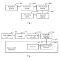
- an embodiment of the invention provides a system for transmitting a video signal, and as illustrated in Fig.5 , the system includes: a camera video core 501, an encoder 502, a digital-to-analog converter 503, an electrically-conductive slip ring 504, and an analog-to-digital converter 506 and a decoder 507 disposed in a master control chip board 505;
- the camera video core 501 is configured to acquire a current raw digital video signal
- the encoder 502 is configured to separate the current raw digital video signal acquired by the camera video core 501 into a luminance signal and a chrominance signal; to convert together with the digital-to-analog converter the luminance signal and the chrominance signal into an analog video signal; and to transmit the analog video signal to the master control chip board 505 through the electrically-conductive slip ring 504; and
- the analog-to-digital converter 506 and the decoder 507 disposed in the master control chip board 505 are configured to convert the analog video signal back into the current raw digital video signal.
- the analog video signal can be further particularly embodied as a low-frequency analog video signal.
- the encoder 502 is configured to process the luminance signal by a digital filter and then to baseband-encode it into a luminance-encoded digital signal; to encode the chrominance signal over an intermediate-frequency carrier into a chrominance-encoded digital signal; and to superimpose the luminance-encoded digital signal and the chrominance-encoded digital signal into an encoded digital signal; and the digital-to-analog converter 503 is configured to convert the encoded digital signal into the analog video signal.
- the encoder is configured to process the luminance signal by a digital filter and then to baseband-encode it into a luminance-encoded digital signal, and to convert the luminance-encoded digital signal into a first analog signal by a first digital-to-analog converter 5031; and to encode the chrominance signal over an intermediate-frequency carrier into a chrominance-encoded digital signal, and to convert the chrominance-encoded digital signal 5032 into a second analog signal by a second digital-to-analog converter.
- the number of analog-to-digital converters 506 is the same as the number of digital-to-analog converters 503, and when the number of digital-to-analog converters 503 is one, and the number of analog-to-digital converters 506 is one, the analog-to-digital converter 506 is configured to convert the received analog video signal into the encoded digital signal; and the decoder 507 is configured to decode and convert the encoded digital signal back into the current raw digital video signal; and
- a first analog-to-digital converter 5061 is configured to analog-to-digital convert the first analog signal into the luminance-encoded digital signal
- a second analog-to-digital converter 5062 is configured to analog-to-digital convert the second analog signal into the chrominance-encoded digital signal
- the decoder 507 is configured to decode the luminance-encoded digital signal into the luminance digital signal; to decode the chrominance-encoded digital signal into the chrominance digital signal; and to superimpose and then convert the luminance digital signal and the chrominance digital signal back into the current raw digital video signal.
- system further includes:
- a master processor is configured to transmit the current raw digital video signal to a master processor in the master control chip board for processing after converting back into the current raw digital video signal.
- the current raw digital video signal is separated into the luminance signal and the chrominance signal which are further encoded respectively into the analog video signal.
- the analog video signal is transmitted through the electrically-conductive slip ring, the electrically-conductive slip ring is discontinuous in impedance, but its influence upon the analog video signal can be neglectable due to the low frequency of the analog video signal.
- the analog video signal is further converted by the master control chip board back into the raw digital video signal. As such the integrity of the transmitted video signal can be improved to thereby guarantee the quality of the video signal.
- the embodiments of the invention can be embodied as a method, a system or a computer program product. Therefore the invention can be embodied in the form of an all-hardware embodiment, an all-software embodiment or an embodiment of software and hardware in combination. Furthermore the invention can be embodied in the form of a computer program product embodied in one or more computer useable storage mediums (including but not limited to a disk memory, a CD-ROM, an optical memory, etc.) in which computer useable program codes are contained.
- a computer useable storage mediums including but not limited to a disk memory, a CD-ROM, an optical memory, etc.
- These computer program instructions can also be stored into a computer readable memory capable of directing the computer or the other programmable data processing device to operate in a specific manner so that the instructions stored in the computer readable memory create an article of manufacture including instruction means which perform the functions specified in the flow(s) of the flow chart and/or the block(s) of the block diagram.
- These computer program instructions can also be loaded onto the computer or the other programmable data processing device so that a series of operational steps are performed on the computer or the other programmable data processing device to create a computer implemented process so that the instructions executed on the computer or the other programmable device provide the steps for performing the functions specified in the flow(s) of the flow chart and/or the block(s) of the block diagram.
Landscapes
- Engineering & Computer Science (AREA)
- Multimedia (AREA)
- Signal Processing (AREA)
- Studio Devices (AREA)
- Compression Or Coding Systems Of Tv Signals (AREA)
- Color Television Systems (AREA)
Abstract
Description
- This application claims the benefit of Chinese Patent Application No.
201210156042.5 - The present invention relates to the field of communications and particularly to a video signal transmission method, apparatus, system and terminal.
- In the safety and guard industry, there are high requirements on a high-definition video image, and particularly the requirements on 720p, 1280p and other high-definition video formats have gradually evolved as a standard in the industry. At present a high-definition spherical video camera also has to accommodate the demand for a high-definition video. The high-definition spherical video camera is generally embodied in the form of products including a network spherical video camera and a Serial Digital Interface (SDI) spherical video camera, and in order to enable a video camera core inside the spherical video camera to be rotated horizontally over 360 degrees and vertically over 90 or 180 degrees arbitrarily, the video camera core and the master control board are connected by an electrically-conductive slip ring to thereby guarantee the reliability in electrical connection of the video camera core during rotation. At present the following two transmission schemes are generally adopted for 720p, 1280p and other high-definition video formats:
- Firstly a video signal output by the video camera core is converted into a High Definition-Serial Digital Interface (HD-SDI) signal and transmitted to the control board through the electrically-conductive slip ring, but the clock frequency of the HD-SDI signal is approximately 1.485GHz, so the digital signal at the high clock frequency can not be transmitted over a conventional electrically-conductive slip ring, therefore an expensive and process-complicated specialized electrically-conductive slip ring has to be customized, and the transmitted signal may be susceptible to interference.
- Secondly the video signal output by the video camera core is converted into a multi-channel Low-Voltage Differential Signaling (LVDS) signal transmitted to the control board through the electrically-conductive slip ring by transmitting the differential signal over a plurality of channels for the purpose of sharing the amount of data. Taking five channels as an example, the signal is transmitted at the clock frequency of 27MHz, but the frequency of the transmitted signal is still high and susceptible to interference, and there is a high requirement on the performance of the electrically-conductive slip ring. Moreover a plurality of transmission cables added as a result of a significant increase in number of channels and of an externally applied synchronization clock may also result in a significant increase in volume of the electrically-conductive slip ring and consequentially an increase in cost thereof. As a result, the structure of the spherical video camera may be restricted by the volume of the electrically-conductive slip ring and consequentially can not be minimized.
- In summary, the electrically-conductive slip ring characterized by discontinuous impedance and a large number of joints thereof may impose a considerable negative influence upon the integrity, the quality of signal and other aspects of a high-frequency digital signal or an analog signal, thus degrading the accuracy of transmitted video images and consequently resulting in blocking, dithering, a frame loss and other problems of the images. Moreover the volume of the spherical video camera may be limited.
- Embodiments of the invention provide a video signal transmission method, apparatus, system and terminal so as to improve the integrity of a transmitted signal and guarantee the quality of the signal.
- An embodiment of the invention provides a method of transmitting a video signal, the method including:
- separating a current raw digital video signal acquired by a video camera core into a luminance signal and a chrominance signal;
- converting the luminance signal and the chrominance signal into an analog video signal;
- transmitting the analog video signal to a master control chip board through an electrically-conductive slip ring; and
- converting the analog video signal back into the current raw digital video signal in the master control chip board.
- Correspondingly an embodiment of the invention provides an apparatus for transmitting a video signal, the apparatus including:
- a separation module configured to separate a current raw digital video signal acquired by a video camera core into a luminance signal and a chrominance signal;
- a conversion module configured to convert the luminance signal and the chrominance signal into an analog video signal;
- a transmission module configured to transmit the analog video signal to a master control chip board through an electrically-conductive slip ring; and
- a recovery module configured to convert the analog video signal back into the current raw digital video signal in the master control chip board.
- Correspondingly an embodiment of the invention provides a terminal including the apparatus for transmitting a video signal described above.
- Correspondingly an embodiment of the invention provides a system for transmitting a video signal, the system including a video camera core, an encoder, a digital-to-analog converter, an electrically-conductive slip ring, and an analog-to-digital converter and a decoder, both of which are disposed in a master control chip board, wherein:
- the camera video core is configured to acquire a current raw digital video signal;
- the encoder is configured to separate the current raw digital video signal acquired by the camera video core into a luminance signal and a chrominance signal; to convert together with the digital-to-analog converter the luminance signal and the chrominance signal into an analog video signal; and to transmit the analog video signal to the master control chip board through the electrically-conductive slip ring; and
- the analog-to-digital converter and the decoder disposed in the master control chip board are configured to convert the analog video signal back into the current raw digital video signal.
- The embodiments of the invention provide a video signal transmission method, apparatus, system and terminal, where a current raw digital video signal acquired by a video camera core is separated into a luminance signal and a chrominance signal; the luminance signal and the chrominance signal are converted into an analog video signal; the analog video signal is transmitted to a master control chip board through an electrically-conductive slip ring; and the analog video signal is converted back into the current raw digital video signal in the master control chip board. With the video signal transmission method, apparatus, system and terminal according to the embodiments of the invention, the current raw digital video signal is separated into the luminance signal and the chrominance signal which are further encoded respectively into the analog video signal. When the analog video signal is transmitted through the electrically-conductive slip ring, the electrically-conductive slip ring is discontinuous in impedance, but its influence upon the analog video signal can be neglectable due to the low frequency of the analog video signal. Correspondingly the analog video signal is further converted by the master control chip board back into the raw digital video signal. As such the integrity of the transmitted video signal can be improved to thereby guarantee the quality of the video signal.
-
-
Fig.1 is a schematic flow chart of a method of transmitting a video signal according to an embodiment of the invention; -
Fig.2 is a schematic flow chart of a method of transmitting a video signal according to another embodiment of the invention; -
Fig.3 is a schematic flow chart of a method of transmitting a video signal according to still another embodiment of the invention; -
Fig.4 is a schematic diagram of an apparatus for transmitting a video signal according to an embodiment of the invention; -
Fig.5 is a schematic diagram of a system for transmitting a video signal according to an embodiment of the invention; and -
Fig.6 is a schematic diagram of a system for transmitting a video signal according to another embodiment of the invention. - A general implementation principle, particular implementations and corresponding advantageous effects thereof of the technical solutions according to the embodiments of the invention will be described below in details with reference to the drawings.
- In order to address the problems in the prior art, an embodiment of the invention provides a method of transmitting a video signal, and as illustrated in
Fig.1 , the method includes: - The
step 101 is to separate a current raw digital video signal acquired by a video camera core into a luminance signal and a chrominance signal; - The
step 102 is to convert the luminance signal and the chrominance signal into an analog video signal; - The
step 103 is to transmit the analog video signal to a master control chip board through an electrically-conductive slip ring; and - The
step 104 is to convert the analog video signal back into the current raw digital video signal in the master control chip board. - In view of the drawbacks of the prior art, the current raw digital video signal acquired by the video camera core is converted into the analog video signal for transmission in the method according to the embodiment of the invention, where the raw digital video signal is firstly separated into the luminance signal and the chrominance signal, and then the luminance signal and the chrominance signal are converted into the analog video signal. Particularly the luminance signal is processed by a digital filter and then baseband-encoded into a luminance-encoded digital signal; the chrominance signal is encoded over an intermediate-frequency carrier into a chrominance-encoded digital signal; and the luminance-encoded digital signal and the chrominance-encoded digital signal are superimposed into an encoded digital signal which is further digital-to-analog converted into the analog video signal. Then the analog video signal is transmitted to the master control chip board through the electrically-conductive slip ring. Correspondingly the received analog video signal is converted by the master control chip board back into the current raw digital video signal. Particularly the received analog video signal is analog-to-digital converted into the encoded digital signal; and the encoded digital signal is decoded into the current raw digital video signal.
- Particularly it will be sufficient if the frequency of the analog video signal is below an upper transmission limit of an electrical signal for the electrically-conductive slip ring, and in order to lower a cost and improve the reliability in processing and transmission of the analog video signal as well as avoid wearing from occurring as a result of rotation of the electrically-conductive slip ring at a high speed for a long period of time and thus making the signal instable, the analog video signal in the embodiment of the invention can be further particularly embodied as a low-frequency analog video signal.
- The luminance-encoded digital signal and the chrominance-encoded digital signal described above can be converted respectively into a first analog signal and a second analog signal, and then these two analog signals are converted respectively by the master control chip board into digital signals for further superimposition to thereby have the analog video signal converted back into the current raw digital video signal. Particularly the luminance signal is processed by the digital filter and then baseband-encoded into the luminance-encoded digital signal; the luminance-encoded digital signal is digital-to-analog converted into the first analog signal; and the chrominance signal is encoded over the intermediate-frequency carrier into the chrominance-encoded digital signal; and the chrominance-encoded digital signal is digital-to-analog converted into the second analog signal. The first analog signal and the second analog signal are respectively transmitted to the master control chip board through the electrically-conductive slip ring. Correspondingly the first analog signal is analog-to-digital converted by the master control chip board into the luminance-encoded digital signal, and the luminance-encoded digital signal is further encoded into the luminance digital signal; and the second analog signal is analog-to-digital converted into the chrominance-encoded digital signal, and the chrominance-encoded digital signal is encoded into the chrominance digital signal; and the luminance digital signal and the chrominance digital signal are superimposed and then converted into the current raw digital video signal. The received analog video signal is converted by the master control chip board back into the current raw digital video signal, and then the current raw digital video signal can be transmitted to a master processor in the master control chip board for processing.
- The disclosure above will be described below in details in connection particular embodiments thereof, and as illustrated in
Fig.2 , the current raw digital video signal is converted into an analog signal transmitted to the master control chip board through the electrically-conductive slip ring in the following steps: - In the
step 201, the current raw digital video signal acquired by the camera video core is separated in the encoder into the luminance signal and the chrominance signal. - In the
step 202, the luminance signal is filtered by the digital filter and then baseband-encoded in the encoder into the luminance-encoded digital signal; and the chrominance signal is encoded over the intermediate-frequency carrier into the chrominance-encoded digital signal; - Particularly the video camera chip in a high-definition video camera can acquire continuously a high-definition video in a digital signal pattern. Then the video camera chip outputs a 16-bit digital signal in the YCbCr format (the raw digital signal), and the encoder separates the current raw digital video signal into the luminance signal and the chrominance signal and processes these two signals through analog encoding. For example, the luminance signal is processed by the digital filter and then baseband-encoded into the luminance-encoded digital signal; and the chrominance signal is encoded over the intermediate-frequency carrier into the chrominance-encoded digital signal, where for 25-frame and 30-frame high-definition videos in the 720P format, the luminance signal is filtered by the 15MHz digital filter and encoded over the 18MHz intermediate-frequency carrier as per the horizontal resolution thereof into the analog video signal; and for 25-frame and 30-frame high-definition videos in the 1080P format and 50-frame and 60-frame high-definition videos in the 720P format, the luminance signal is filtered by the 30MHz digital filter and encoded over the 36MHz intermediate-frequency carrier as per the horizontal resolution thereof into the analog video signal.
- In the
step 203, the encoder superimposes the luminance-encoded digital signal and the chrominance-encoded digital signal into the encoded digital signal transmitted to the digital-to-analog converter; and particularly the encoder superimposes the luminance-encoded digital signal and the chrominance-encoded digital signal of the current raw digital video signal into the encoded digital signal. - In the
step 204, the digital-to-analog converter digital-to-analog converts the received encoded digital signal into the analog video signal; and particularly if the 15MHz digital filter and encoding over the 18MHz intermediate-frequency carrier is selected in thestep 202, then the analog video signal output by the digital-to-analog converter as a result of conversion can be up to 20MHz. Moreover the frequency of the analog video signal can be controlled by selecting the digital-to-analog converter varying in precision. - In the
step 205, the analog signal is transmitted to the master control chip board through the electrically-conductive slip ring; and particularly an influence of the impedance of the electrically-conductive slip ring upon the analog video signal transmitted through the electrically-conductive slip ring may ideally be neglectable due to the low frequency of the analog video signal. - In the
step 206, the analog-to-digital converter in the master control chip board analog-to-digital converts the received analog video signal into the encoded digital signal; and the encoded digital signal here is the same as the encoded digital signal formed in thestep 203. Preferably the analog-to-digital converter has the same precision as the digital-to-analog converter described above to thereby further ensure the encoded digital signal prior to digital-to-analog conversion to be the same as the encoded digital signal as a result of analog-to-digital conversion. - In the
step 207, the decoder decodes and converts the encoded digital signal to back into the current raw digital video signal described above. - In the
step 208, the master processor subsequently processes the current raw digital video signal. - As illustrated in
Fig.3 , the raw digital video signal is converted into two analog video signals transmitted to the master control chip board through the electrically-conductive slip ring in the following steps: - In the
step 301, the current raw digital video signal acquired by the camera video core is separated in the encoder into the luminance signal and the chrominance signal. - In the
step 302, the luminance signal is filtered by the digital filter and then baseband-encoded in the encoder into the luminance-encoded digital signal; and the chrominance signal is encoded over the intermediate-frequency carrier into the chrominance-encoded digital signal; - Particularly the video camera chip in a high-definition video camera can acquire continuously a high-definition video in a digital signal pattern. Then the video camera chip outputs a 16-bit digital signal in the YCbCr format (the raw digital signal), and the encoder separates the current raw digital video signal into the luminance signal and the chrominance signal and processes these two signals through analog encoding. For example, the luminance signal is processed by the digital filter and then baseband-encoded into the luminance-encoded digital signal; and the chrominance signal is encoded over the intermediate-frequency carrier into the chrominance-encoded digital signal, where for 25-frame and 30-frame high-definition videos in the 720P format, the luminance signal is filtered by the 15MHz digital filter and encoded over the 18MHz intermediate-frequency carrier as per the horizontal resolution thereof into the analog video signal; and for 25-frame and 30-frame high-definition videos in the 1080P format and 50-frame and 60-frame high-definition videos in the 720P format, the luminance signal is filtered by the 30MHz digital filter and encoded over the 36MHz intermediate-frequency carrier as per the horizontal resolution thereof into the analog video signal.
- In the
step 303, the encoder transmits the luminance-encoded digital signal to a first digital-to-analog converter and the chrominance-encoded digital signal to a second digital-to-analog converter. - In the
step 304, the first digital-to-analog converter converts the luminance-encoded digital signal into the first analog signal; and the second digital-to-analog converter converts the chrominance-encoded digital signal into the second analog signal. - In the
step 305, the first analog signal and the second analog signal are respectively transmitted to the master control chip board through the electrically-conductive slip ring. - In the
step 306, a first analog-to-digital converter in the master control chip board converts the first analog signal into the luminance-encoded digital signal, and a second analog-to-digital converter converts the second analog signal into the chrominance-encoded digital signal. - In the
step 307, the decoder decodes the luminance-encoded digital signal into the luminance digital signal; and decodes the chrominance-encoded digital signal into the chrominance digital signal. - In the
step 308, the decoder superimposes and then converts the luminance digital signal and the chrominance digital signal back into the current raw digital video signal. - In the
step 309, the current raw digital video signal is transmitted to the master processor in the master control chip board for processing. - As can be apparent from the description above, with the method of transmitting a video signal according to the embodiment of the invention, the current raw digital video signal is separated into the luminance signal and the chrominance signal which are further encoded respectively into the analog video signal, and when the analog video signal is transmitted through the electrically-conductive slip ring, the electrically-conductive slip ring is discontinuous in impedance, but its influence upon the analog video signal can be neglectable due to the low frequency of the analog video signal. Correspondingly the analog video signal is further converted by the master control chip board back into the raw digital video signal. As such the integrity of the transmitted video signal can be improved to thereby guarantee the quality of the video signal.
- Based upon the same inventive idea, an embodiment of the invention further provides an apparatus for transmitting a video signal, and as illustrated in
Fig.4 , the apparatus includes: - A
separation module 401 is configured to separate a current raw digital video signal acquired by a video camera core into a luminance signal and a chrominance signal; - A
conversion module 402 is configured to convert the luminance signal and the chrominance signal into an analog video signal; - A
transmission module 403 is configured to transmit the analog video signal to a master control chip board through an electrically-conductive slip ring; and - A
recovery module 404 is configured to convert the analog video signal back into the current raw digital video signal in the master control chip board. - In order to lower a cost and improve the reliability in processing and transmission of the analog video signal as well as avoid wearing from occurring as a result of rotation of the electrically-conductive slip ring at a high speed for a long period of time and thus making the signal instable, the analog video signal can be further particularly embodied as a low-frequency analog video signal.
- Preferably the
conversion module 402 is further configured to process the luminance signal by a digital filter and then to baseband-encode it into a luminance-encoded digital signal; to encode the chrominance signal over an intermediate-frequency carrier into a chrominance-encoded digital signal; and to superimpose the luminance-encoded digital signal and the chrominance-encoded digital signal into an encoded digital signal and then convert the encoded digital signal into the analog video signal by a digital-to-analog converter. Preferably therecovery module 404 is further configured to analog-to-digital convert the received analog video signal into the encoded digital signal; and to decode the encoded digital signal back into the current raw digital video signal. - Preferably the
conversion module 402 is further configured to process the luminance signal by a digital filter and then to baseband-encode it into a luminance-encoded digital signal, and to convert the luminance-encoded digital signal into a first analog signal by a digital-to-analog converter; and to encode the chrominance signal over an intermediate-frequency carrier into a chrominance-encoded digital signal, and to convert the chrominance-encoded digital signal into a second analog signal by a digital-to-analog converter. Preferably therecovery module 404 is further configured to analog-to-digital convert the first analog signal into the luminance-encoded digital signal and to decode the luminance-encoded digital signal into the luminance digital signal; to analog-to-digital convert the second analog signal into the chrominance-encoded digital signal and to decode the chrominance-encoded digital signal into the chrominance digital signal; and to superimpose and then convert the luminance digital signal and the chrominance digital signal back into the current raw digital video signal. - Preferably the apparatus further includes:
- A
processing module 405 is configured to transmit the current raw digital video signal to a master processor in the master control chip board for processing after therecovery module 404 converts the analog video signal back into the current raw digital video signal. - Based upon the same inventive idea, an embodiment of the invention provides a terminal including the apparatus for transmitting a video signal described above.
- As can be apparent from the description above, with the apparatus for transmitting a video signal according to the embodiment of the invention, the current raw digital video signal is separated into the luminance signal and the chrominance signal which are further encoded respectively into the analog video signal. When the analog video signal is transmitted through the electrically-conductive slip ring, the electrically-conductive slip ring is discontinuous in impedance, but its influence upon the analog video signal can be neglectable due to the low frequency of the analog video signal. Correspondingly the analog video signal is further converted by the master control chip board back into the raw digital video signal. As such the integrity of the transmitted video signal can be improved to thereby guarantee the quality of the video signal.
- Based upon the same inventive idea, an embodiment of the invention provides a system for transmitting a video signal, and as illustrated in
Fig.5 , the system includes: acamera video core 501, anencoder 502, a digital-to-analog converter 503, an electrically-conductive slip ring 504, and an analog-to-digital converter 506 and adecoder 507 disposed in a mastercontrol chip board 505; - The
camera video core 501 is configured to acquire a current raw digital video signal; - The
encoder 502 is configured to separate the current raw digital video signal acquired by thecamera video core 501 into a luminance signal and a chrominance signal; to convert together with the digital-to-analog converter the luminance signal and the chrominance signal into an analog video signal; and to transmit the analog video signal to the mastercontrol chip board 505 through the electrically-conductive slip ring 504; and - The analog-to-
digital converter 506 and thedecoder 507 disposed in the mastercontrol chip board 505 are configured to convert the analog video signal back into the current raw digital video signal. - Moreover, in order to lower a cost and improve the reliability in processing and transmission of the analog video signal as well as avoid wearing from occurring as a result of rotation of the electrically-conductive slip ring at a high speed for a long period of time and thus making the signal instable, the analog video signal can be further particularly embodied as a low-frequency analog video signal.
- Preferably when the number of digital-to-
analog converters 503 is one, theencoder 502 is configured to process the luminance signal by a digital filter and then to baseband-encode it into a luminance-encoded digital signal; to encode the chrominance signal over an intermediate-frequency carrier into a chrominance-encoded digital signal; and to superimpose the luminance-encoded digital signal and the chrominance-encoded digital signal into an encoded digital signal; and the digital-to-analog converter 503 is configured to convert the encoded digital signal into the analog video signal. - As illustrated in
Fig.6 , based uponFig.5 , when the number of digital-to-analog converters is two, the encoder is configured to process the luminance signal by a digital filter and then to baseband-encode it into a luminance-encoded digital signal, and to convert the luminance-encoded digital signal into a first analog signal by a first digital-to-analog converter 5031; and to encode the chrominance signal over an intermediate-frequency carrier into a chrominance-encoded digital signal, and to convert the chrominance-encodeddigital signal 5032 into a second analog signal by a second digital-to-analog converter. - Preferably as illustrated in
Fig.5 , the number of analog-to-digital converters 506 is the same as the number of digital-to-analog converters 503, and when the number of digital-to-analog converters 503 is one, and the number of analog-to-digital converters 506 is one, the analog-to-digital converter 506 is configured to convert the received analog video signal into the encoded digital signal; and thedecoder 507 is configured to decode and convert the encoded digital signal back into the current raw digital video signal; and - As illustrated in
Fig.6 , when the number of digital-to-analog converters is two, and the number of analog-to-digital converters is two, a first analog-to-digital converter 5061 is configured to analog-to-digital convert the first analog signal into the luminance-encoded digital signal; and a second analog-to-digital converter 5062 is configured to analog-to-digital convert the second analog signal into the chrominance-encoded digital signal; and thedecoder 507 is configured to decode the luminance-encoded digital signal into the luminance digital signal; to decode the chrominance-encoded digital signal into the chrominance digital signal; and to superimpose and then convert the luminance digital signal and the chrominance digital signal back into the current raw digital video signal. - Preferably the system further includes:
- A master processor is configured to transmit the current raw digital video signal to a master processor in the master control chip board for processing after converting back into the current raw digital video signal.
- As can be apparent from the description above, with the video signal transmission method, apparatus, system and terminal according to the embodiments of the invention, the current raw digital video signal is separated into the luminance signal and the chrominance signal which are further encoded respectively into the analog video signal. When the analog video signal is transmitted through the electrically-conductive slip ring, the electrically-conductive slip ring is discontinuous in impedance, but its influence upon the analog video signal can be neglectable due to the low frequency of the analog video signal. Correspondingly the analog video signal is further converted by the master control chip board back into the raw digital video signal. As such the integrity of the transmitted video signal can be improved to thereby guarantee the quality of the video signal.
- Those skilled in the art shall appreciate that the embodiments of the invention can be embodied as a method, a system or a computer program product. Therefore the invention can be embodied in the form of an all-hardware embodiment, an all-software embodiment or an embodiment of software and hardware in combination. Furthermore the invention can be embodied in the form of a computer program product embodied in one or more computer useable storage mediums (including but not limited to a disk memory, a CD-ROM, an optical memory, etc.) in which computer useable program codes are contained.
- The invention has been described in a flow chart and/or a block diagram of the method, the device (system) and the computer program product according to the embodiments of the invention. It shall be appreciated that respective flows and/or blocks in the flow chart and/or the block diagram and combinations of the flows and/or the blocks in the flow chart and/or the block diagram can be embodied in computer program instructions. These computer program instructions can be loaded onto a general-purpose computer, a specific-purpose computer, an embedded processor or a processor of another programmable data processing device to produce a machine so that the instructions executed on the computer or the processor of the other programmable data processing device create means for performing the functions specified in the flow(s) of the flow chart and/or the block(s) of the block diagram.
- These computer program instructions can also be stored into a computer readable memory capable of directing the computer or the other programmable data processing device to operate in a specific manner so that the instructions stored in the computer readable memory create an article of manufacture including instruction means which perform the functions specified in the flow(s) of the flow chart and/or the block(s) of the block diagram.
- These computer program instructions can also be loaded onto the computer or the other programmable data processing device so that a series of operational steps are performed on the computer or the other programmable data processing device to create a computer implemented process so that the instructions executed on the computer or the other programmable device provide the steps for performing the functions specified in the flow(s) of the flow chart and/or the block(s) of the block diagram.
- Although the preferred embodiments of the invention have been described, those skilled in the art benefiting from the underlying inventive concept can make additional modifications and variations to these embodiments. Therefore the appended claims are intended to be construed as encompassing the preferred embodiments and all the modifications and variations coming into the scope of the invention.
- Evidently those skilled in the art can make various modifications and variations to the invention without departing from the spirit and scope of the invention. Thus the invention is also intended to encompass these modifications and variations thereto so long as the modifications and variations come into the scope of the claims appended to the invention and their equivalents.
Claims (20)
- A method of transmitting a video signal, comprising:separating a current raw digital video signal acquired by a video camera core into a luminance signal and a chrominance signal;converting the luminance signal and the chrominance signal into an analog video signal;transmitting the analog video signal to a master control chip board through an electrically-conductive slip ring; andconverting the analog video signal back into the current raw digital video signal in the master control chip board.
- The method according to claim 1, wherein the analog video signal is a low-frequency analog video signal.
- The method according to claim 2, wherein converting the luminance signal and the chrominance signal into the analog video signal comprises:processing the luminance signal by a digital filter and then baseband-encoding it into a luminance-encoded digital signal;encoding the chrominance signal over an intermediate-frequency carrier into a chrominance-encoded digital signal; andsuperimposing the luminance-encoded digital signal and the chrominance-encoded digital signal into an encoded digital signal and then converting the encoded digital signal into an analog video signal.
- The method according to claim 3, wherein converting the analog video signal back into the current raw digital video signal in the master control chip board comprises:analog-to-digital converting the received analog video signal into the encoded digital signal; anddecoding the encoded digital signal back into the current raw digital video signal.
- The method according to claim 2, wherein converting the luminance signal and the chrominance signal into the analog video signal comprises:processing the luminance signal by a digital filter and then baseband-encoding it into a luminance-encoded digital signal, and digital-to-analog converting the luminance-encoded digital signal into a first analog signal; andencoding the chrominance signal over an intermediate-frequency carrier into a chrominance-encoded digital signal, and digital-to-analog converting the chrominance-encoded digital signal into a second analog signal.
- The method according to claim 5, wherein converting the analog video signal back into the current raw digital video signal in the master control chip board comprises:analog-to-digital converting the first analog signal into the luminance-encoded digital signal and decoding the luminance-encoded digital signal into the luminance digital signal;analog-to-digital converting the second analog signal into the chrominance-encoded digital signal and decoding the chrominance-encoded digital signal into the chrominance digital signal; andsuperimposing and then converting the luminance digital signal and the chrominance digital signal back into the current raw digital video signal.
- The method according to claim 2 or 4 or 6, wherein after the analog video signal is converted back into the current raw digital video signal in the master control chip board, the method further comprises:transmitting the current raw digital video signal to a master processor in the master control chip board for processing.
- An apparatus for transmitting a video signal, comprising:a separation module configured to separate a current raw digital video signal acquired by a video camera core into a luminance signal and a chrominance signal;a conversion module configured to convert the luminance signal and the chrominance signal into an analog video signal;a transmission module configured to transmit the analog video signal to a master control chip board through an electrically-conductive slip ring; anda recovery module configured to convert the analog video signal back into the current raw digital video signal in the master control chip board.
- The apparatus according to claim 8, wherein the analog video signal is a low-frequency analog video signal.
- The apparatus according to claim 9, wherein the conversion module is further configured to process the luminance signal by a digital filter and then to baseband-encode it into a luminance-encoded digital signal; to encode the chrominance signal over an intermediate-frequency carrier into a chrominance-encoded digital signal; and to superimpose the luminance-encoded digital signal and the chrominance-encoded digital signal into an encoded digital signal and then convert the encoded digital signal into the analog video signal by a digital-to-analog converter.
- The apparatus according to claim 10, wherein the recovery module is further configured to analog-to-digital convert the received analog video signal into the encoded digital signal; and to decode the encoded digital signal back into the current raw digital video signal.
- The apparatus according to claim 9, wherein the conversion module is further configured to process the luminance signal by a digital filter and then to baseband-encode it into a luminance-encoded digital signal, and to convert the luminance-encoded digital signal into a first analog signal by a digital-to-analog converter; and to encode the chrominance signal over an intermediate-frequency carrier into a chrominance-encoded digital signal, and to convert the chrominance-encoded digital signal into a second analog signal by a digital-to-analog converter.
- The apparatus according to claim 12, wherein the recovery module is further configured to analog-to-digital convert the first analog signal into the luminance-encoded digital signal and to decode the luminance-encoded digital signal into the luminance digital signal; to analog-to-digital convert the second analog signal into the chrominance-encoded digital signal and to decode the chrominance-encoded digital signal into the chrominance digital signal; and to superimpose and then convert the luminance digital signal and the chrominance digital signal back into the current raw digital video signal.
- The apparatus according to claim 9 or 11 or 13, wherein the apparatus further comprises:a processing module configured to transmit the current raw digital video signal to a master processor in the master control chip board for processing after the recovery module converts the analog signal back into the current raw digital video signal in the master control chip.
- A terminal, comprising the apparatus for transmitting a video signal according to any one of claims 8 to 14.
- A system for transmitting a video signal, comprising: a camera video core, an encoder, a digital-to-analog converter, an electrically-conductive slip ring, and an analog-to-digital converter and a decoder disposed in a master control chip board, wherein:the camera video core is configured to acquire a current raw digital video signal;the encoder is configured to separate the current raw digital video signal acquired by the camera video core into a luminance signal and a chrominance signal; to convert together with the digital-to-analog converter the luminance signal and the chrominance signal into an analog video signal; and to transmit the analog video signal to the master control chip board through the electrically-conductive slip ring; andthe analog-to-digital converter and the decoder disposed in the master control chip board are configured to convert the analog video signal back into the current raw digital video signal.
- The system according to claim 16, wherein the analog video signal is a low-frequency analog video signal.
- The system according to claim 17, wherein when the system comprises one digital-to-analog converter, the encoder is configured to process the luminance signal by a digital filter and then to baseband-encode it into a luminance-encoded digital signal; to encode the chrominance signal over an intermediate-frequency carrier into a chrominance-encoded digital signal; and to superimpose the luminance-encoded digital signal and the chrominance-encoded digital signal into an encoded digital signal; and the digital-to-analog converter is configured to convert the encoded digital signal into the analog video signal; and
when the system comprises two digital-to-analog converters, the encoder is configured to process the luminance signal by a digital filter and then to baseband-encode it into a luminance-encoded digital signal, and to convert the luminance-encoded digital signal into a first analog signal by a first digital-to-analog converter; and to encode the chrominance signal over an intermediate-frequency carrier into a chrominance-encoded digital signal, and to convert the chrominance-encoded digital signal into a second analog signal by a second digital-to-analog converter. - The system according to claim 18, wherein the number of analog-to-digital converters is the same as the number of digital-to-analog converters; and
when the system comprises one digital-to-analog converter and one analog-to-digital converter, the analog-to-digital converter is configured to convert the received analog video signal into the encoded digital signal; and the decoder is configured to decode and convert the encoded digital signal back into the current raw digital video signal, and
when the system comprises two digital-to-analog converters and two analog-to-digital converters, a first analog-to-digital converter is configured to analog-to-digital convert the first analog signal into the luminance-encoded digital signal; and a second analog-to-digital converter is configured to analog-to-digital convert the second analog signal into the chrominance-encoded digital signal; and the decoder is configured to decode the luminance-encoded digital signal into the luminance digital signal; to decode the chrominance-encoded digital signal into the chrominance digital signal; and to superimpose and then convert the luminance digital signal and the chrominance digital signal back into the current raw digital video signal. - The system according to claim 18, wherein the system further comprises:a master processor configured to transmit the current raw digital video signal to a master processor in the master control chip board for processing after the analog-to-digital converter and the decoder in the master control chip board converts the analog video signal back into the current raw digital video signal.
Applications Claiming Priority (2)
| Application Number | Priority Date | Filing Date | Title |
|---|---|---|---|
| CN201210156042.5A CN102724517B (en) | 2012-05-16 | 2012-05-16 | Method, device and system for video signal transmission, and terminals |
| PCT/CN2013/075716 WO2013170765A1 (en) | 2012-05-16 | 2013-05-16 | Video signal transmission method, device, system and terminal |
Publications (3)
| Publication Number | Publication Date |
|---|---|
| EP2814247A1 true EP2814247A1 (en) | 2014-12-17 |
| EP2814247A4 EP2814247A4 (en) | 2015-11-04 |
| EP2814247B1 EP2814247B1 (en) | 2020-09-02 |
Family
ID=46950161
Family Applications (1)
| Application Number | Title | Priority Date | Filing Date |
|---|---|---|---|
| EP13791567.4A Active EP2814247B1 (en) | 2012-05-16 | 2013-05-16 | Video signal transmission method, device, system and terminal |
Country Status (5)
| Country | Link |
|---|---|
| US (1) | US9578297B2 (en) |
| EP (1) | EP2814247B1 (en) |
| KR (1) | KR101659992B1 (en) |
| CN (1) | CN102724517B (en) |
| WO (1) | WO2013170765A1 (en) |
Families Citing this family (6)
| Publication number | Priority date | Publication date | Assignee | Title |
|---|---|---|---|---|
| CN102724517B (en) * | 2012-05-16 | 2014-06-04 | 浙江大华技术股份有限公司 | Method, device and system for video signal transmission, and terminals |
| CN106131509A (en) * | 2016-08-25 | 2016-11-16 | 广西小草信息产业有限责任公司 | A kind of video monitoring system and its implementation |
| CN107396096B (en) * | 2017-08-29 | 2019-03-15 | 中国北方车辆研究所 | Method for testing digital video signal transmission performance for conductive slip ring |
| US10756926B2 (en) * | 2018-07-01 | 2020-08-25 | Benchmark Electronics, Inc. | System and method for transmission of video and controller area network (CAN) data over a power slip ring assembly |
| CN116708891A (en) * | 2023-06-24 | 2023-09-05 | 南通同洲电子有限责任公司 | A video decoding system and decoding method for reducing signal noise |
| US20260116186A1 (en) * | 2024-10-31 | 2026-04-30 | Fca Us Llc | Heads up display with inertial measurement correction for accurate eye tracking |
Family Cites Families (14)
| Publication number | Priority date | Publication date | Assignee | Title |
|---|---|---|---|---|
| NL8300077A (en) * | 1983-01-11 | 1984-08-01 | Philips Nv | VIDEO RECORDING DEVICE. |
| JPH099270A (en) * | 1995-06-23 | 1997-01-10 | Sony Corp | Video camera and video camera device |
| JPH0996756A (en) * | 1995-09-29 | 1997-04-08 | Canon Inc | Lens device and imaging device |
| JP3688399B2 (en) * | 1996-07-26 | 2005-08-24 | 株式会社東芝 | Distortion correction circuit |
| JP3595657B2 (en) * | 1997-08-22 | 2004-12-02 | キヤノン株式会社 | Video signal processing apparatus and method |
| JP4274161B2 (en) * | 2005-08-11 | 2009-06-03 | ソニー株式会社 | Imaging system |
| CN101179708B (en) * | 2007-10-31 | 2010-06-23 | 天津市亚安科技电子有限公司 | Circuit of S video and compound video simultaneous output suitable for platform camera |
| KR100940176B1 (en) | 2007-12-24 | 2010-02-03 | 에스케이 텔레콤주식회사 | Webcam based image reconstruction system and method, and apparatus applied thereto |
| CN201556285U (en) * | 2009-09-16 | 2010-08-18 | 中国科学院沈阳自动化研究所 | A replacement device for signal slip ring of turntable |
| JP2011082652A (en) * | 2009-10-05 | 2011-04-21 | Canon Inc | Universal head device |
| KR100957843B1 (en) | 2009-11-03 | 2010-05-14 | 주식회사 유비샘 | System for managing realtime delivery and order based on cuisine image photographed by web-camera |
| CN102014277B (en) * | 2010-12-03 | 2013-05-15 | 杭州海康威视数字技术股份有限公司 | Video monitoring system, video monitoring method and spherical camera |
| CN102186073B (en) * | 2011-04-27 | 2015-07-29 | 浙江大华技术股份有限公司 | HD-SDI video signal transmission system in high speed ball-type camera and method |
| CN102724517B (en) * | 2012-05-16 | 2014-06-04 | 浙江大华技术股份有限公司 | Method, device and system for video signal transmission, and terminals |
-
2012
- 2012-05-16 CN CN201210156042.5A patent/CN102724517B/en active Active
-
2013
- 2013-05-16 KR KR1020147035373A patent/KR101659992B1/en active Active
- 2013-05-16 WO PCT/CN2013/075716 patent/WO2013170765A1/en not_active Ceased
- 2013-05-16 US US14/391,574 patent/US9578297B2/en active Active
- 2013-05-16 EP EP13791567.4A patent/EP2814247B1/en active Active
Also Published As
| Publication number | Publication date |
|---|---|
| US9578297B2 (en) | 2017-02-21 |
| CN102724517B (en) | 2014-06-04 |
| CN102724517A (en) | 2012-10-10 |
| KR101659992B1 (en) | 2016-09-26 |
| US20150070589A1 (en) | 2015-03-12 |
| EP2814247A4 (en) | 2015-11-04 |
| EP2814247B1 (en) | 2020-09-02 |
| WO2013170765A1 (en) | 2013-11-21 |
| KR20150034134A (en) | 2015-04-02 |
Similar Documents
| Publication | Publication Date | Title |
|---|---|---|
| KR101492535B1 (en) | Method, apparatus and system for generating and facilitating mobile high-definition multimedia interface | |
| EP2814247B1 (en) | Video signal transmission method, device, system and terminal | |
| EP2814249A1 (en) | Method and device for transmitting high-definition video signal | |
| US9456232B2 (en) | Signal processing apparatus, signal processing method, program, and signal transmission system | |
| CN102724392B (en) | Method and device for implementing analog high-definition camera shooting | |
| EP2391139A2 (en) | 3D image data transmission and reception | |
| US9479789B2 (en) | Signal processing apparatus, signal processing method, program, and signal transmission system | |
| US20110273623A1 (en) | Signal transmission apparatus and signal transmission method | |
| EP1303145A1 (en) | Signal transmitting device and signal receiving device | |
| US11044439B2 (en) | Signal processing apparatus, signal processing method, program, and signal transmission system | |
| CN202475622U (en) | Automatic SDI video signal recognition system of coding front end | |
| WO2012060569A3 (en) | Apparatus and method for receiving a digital broadcast signal | |
| CN102724516A (en) | Adaptive signal processing method, device and decoder | |
| KR101427552B1 (en) | Method and apparatus for transmitting video siganl | |
| JP5694412B2 (en) | Transmission device, reception device, transmission method, and reception method | |
| US20150244982A1 (en) | Multi-channel sharing apparatus and multi-channel sharing method | |
| US7477168B2 (en) | Apparatus for and method of processing data | |
| KR20140115057A (en) | Closed-circuit television system for transferring compressed, high-resolution digital video signal through coaxial cable | |
| KR101083179B1 (en) | Audio signal delay apparatus and method | |
| US10389972B2 (en) | Video signal transmission device | |
| CN104754288A (en) | Image and sound transmission system | |
| JP5318992B2 (en) | Video transmission program | |
| CN102811334A (en) | System and method for transmitting high-definition video signal in dome camera | |
| JP2019029692A (en) | Transmitting apparatus of digital signal and transmitting method of digital signal | |
| JP2010087980A (en) | Video signal processing method and apparatus therefor |
Legal Events
| Date | Code | Title | Description |
|---|---|---|---|
| PUAI | Public reference made under article 153(3) epc to a published international application that has entered the european phase |
Free format text: ORIGINAL CODE: 0009012 |
|
| 17P | Request for examination filed |
Effective date: 20140912 |
|
| AK | Designated contracting states |
Kind code of ref document: A1 Designated state(s): AL AT BE BG CH CY CZ DE DK EE ES FI FR GB GR HR HU IE IS IT LI LT LU LV MC MK MT NL NO PL PT RO RS SE SI SK SM TR |
|
| AX | Request for extension of the european patent |
Extension state: BA ME |
|
| DAX | Request for extension of the european patent (deleted) | ||
| RIC1 | Information provided on ipc code assigned before grant |
Ipc: H04N 9/78 20060101ALI20150922BHEP Ipc: H04N 7/52 20110101AFI20150922BHEP Ipc: H04N 11/04 20060101ALI20150922BHEP Ipc: H04N 7/18 20060101ALI20150922BHEP Ipc: H04N 5/232 20060101ALI20150922BHEP |
|
| RA4 | Supplementary search report drawn up and despatched (corrected) |
Effective date: 20151005 |
|
| STAA | Information on the status of an ep patent application or granted ep patent |
Free format text: STATUS: EXAMINATION IS IN PROGRESS |
|
| 17Q | First examination report despatched |
Effective date: 20180605 |
|
| GRAP | Despatch of communication of intention to grant a patent |
Free format text: ORIGINAL CODE: EPIDOSNIGR1 |
|
| STAA | Information on the status of an ep patent application or granted ep patent |
Free format text: STATUS: GRANT OF PATENT IS INTENDED |
|
| INTG | Intention to grant announced |
Effective date: 20200428 |
|
| GRAS | Grant fee paid |
Free format text: ORIGINAL CODE: EPIDOSNIGR3 |
|
| GRAA | (expected) grant |
Free format text: ORIGINAL CODE: 0009210 |
|
| STAA | Information on the status of an ep patent application or granted ep patent |
Free format text: STATUS: THE PATENT HAS BEEN GRANTED |
|
| AK | Designated contracting states |
Kind code of ref document: B1 Designated state(s): AL AT BE BG CH CY CZ DE DK EE ES FI FR GB GR HR HU IE IS IT LI LT LU LV MC MK MT NL NO PL PT RO RS SE SI SK SM TR |
|
| REG | Reference to a national code |
Ref country code: GB Ref legal event code: FG4D |
|
| REG | Reference to a national code |
Ref country code: AT Ref legal event code: REF Ref document number: 1310178 Country of ref document: AT Kind code of ref document: T Effective date: 20200915 Ref country code: CH Ref legal event code: EP |
|
| REG | Reference to a national code |
Ref country code: DE Ref legal event code: R096 Ref document number: 602013072189 Country of ref document: DE |
|
| REG | Reference to a national code |
Ref country code: IE Ref legal event code: FG4D |
|
| REG | Reference to a national code |
Ref country code: LT Ref legal event code: MG4D |
|
| PG25 | Lapsed in a contracting state [announced via postgrant information from national office to epo] |
Ref country code: SE Free format text: LAPSE BECAUSE OF FAILURE TO SUBMIT A TRANSLATION OF THE DESCRIPTION OR TO PAY THE FEE WITHIN THE PRESCRIBED TIME-LIMIT Effective date: 20200902 Ref country code: NO Free format text: LAPSE BECAUSE OF FAILURE TO SUBMIT A TRANSLATION OF THE DESCRIPTION OR TO PAY THE FEE WITHIN THE PRESCRIBED TIME-LIMIT Effective date: 20201202 Ref country code: BG Free format text: LAPSE BECAUSE OF FAILURE TO SUBMIT A TRANSLATION OF THE DESCRIPTION OR TO PAY THE FEE WITHIN THE PRESCRIBED TIME-LIMIT Effective date: 20201202 Ref country code: HR Free format text: LAPSE BECAUSE OF FAILURE TO SUBMIT A TRANSLATION OF THE DESCRIPTION OR TO PAY THE FEE WITHIN THE PRESCRIBED TIME-LIMIT Effective date: 20200902 Ref country code: LT Free format text: LAPSE BECAUSE OF FAILURE TO SUBMIT A TRANSLATION OF THE DESCRIPTION OR TO PAY THE FEE WITHIN THE PRESCRIBED TIME-LIMIT Effective date: 20200902 Ref country code: FI Free format text: LAPSE BECAUSE OF FAILURE TO SUBMIT A TRANSLATION OF THE DESCRIPTION OR TO PAY THE FEE WITHIN THE PRESCRIBED TIME-LIMIT Effective date: 20200902 Ref country code: GR Free format text: LAPSE BECAUSE OF FAILURE TO SUBMIT A TRANSLATION OF THE DESCRIPTION OR TO PAY THE FEE WITHIN THE PRESCRIBED TIME-LIMIT Effective date: 20201203 |
|
| REG | Reference to a national code |
Ref country code: NL Ref legal event code: MP Effective date: 20200902 |
|
| REG | Reference to a national code |
Ref country code: AT Ref legal event code: MK05 Ref document number: 1310178 Country of ref document: AT Kind code of ref document: T Effective date: 20200902 |
|
| PG25 | Lapsed in a contracting state [announced via postgrant information from national office to epo] |
Ref country code: LV Free format text: LAPSE BECAUSE OF FAILURE TO SUBMIT A TRANSLATION OF THE DESCRIPTION OR TO PAY THE FEE WITHIN THE PRESCRIBED TIME-LIMIT Effective date: 20200902 Ref country code: RS Free format text: LAPSE BECAUSE OF FAILURE TO SUBMIT A TRANSLATION OF THE DESCRIPTION OR TO PAY THE FEE WITHIN THE PRESCRIBED TIME-LIMIT Effective date: 20200902 Ref country code: PL Free format text: LAPSE BECAUSE OF FAILURE TO SUBMIT A TRANSLATION OF THE DESCRIPTION OR TO PAY THE FEE WITHIN THE PRESCRIBED TIME-LIMIT Effective date: 20200902 |
|
| PG25 | Lapsed in a contracting state [announced via postgrant information from national office to epo] |
Ref country code: EE Free format text: LAPSE BECAUSE OF FAILURE TO SUBMIT A TRANSLATION OF THE DESCRIPTION OR TO PAY THE FEE WITHIN THE PRESCRIBED TIME-LIMIT Effective date: 20200902 Ref country code: CZ Free format text: LAPSE BECAUSE OF FAILURE TO SUBMIT A TRANSLATION OF THE DESCRIPTION OR TO PAY THE FEE WITHIN THE PRESCRIBED TIME-LIMIT Effective date: 20200902 Ref country code: SM Free format text: LAPSE BECAUSE OF FAILURE TO SUBMIT A TRANSLATION OF THE DESCRIPTION OR TO PAY THE FEE WITHIN THE PRESCRIBED TIME-LIMIT Effective date: 20200902 Ref country code: RO Free format text: LAPSE BECAUSE OF FAILURE TO SUBMIT A TRANSLATION OF THE DESCRIPTION OR TO PAY THE FEE WITHIN THE PRESCRIBED TIME-LIMIT Effective date: 20200902 Ref country code: NL Free format text: LAPSE BECAUSE OF FAILURE TO SUBMIT A TRANSLATION OF THE DESCRIPTION OR TO PAY THE FEE WITHIN THE PRESCRIBED TIME-LIMIT Effective date: 20200902 Ref country code: PT Free format text: LAPSE BECAUSE OF FAILURE TO SUBMIT A TRANSLATION OF THE DESCRIPTION OR TO PAY THE FEE WITHIN THE PRESCRIBED TIME-LIMIT Effective date: 20210104 |
|
| PG25 | Lapsed in a contracting state [announced via postgrant information from national office to epo] |
Ref country code: IS Free format text: LAPSE BECAUSE OF FAILURE TO SUBMIT A TRANSLATION OF THE DESCRIPTION OR TO PAY THE FEE WITHIN THE PRESCRIBED TIME-LIMIT Effective date: 20210102 Ref country code: AL Free format text: LAPSE BECAUSE OF FAILURE TO SUBMIT A TRANSLATION OF THE DESCRIPTION OR TO PAY THE FEE WITHIN THE PRESCRIBED TIME-LIMIT Effective date: 20200902 Ref country code: AT Free format text: LAPSE BECAUSE OF FAILURE TO SUBMIT A TRANSLATION OF THE DESCRIPTION OR TO PAY THE FEE WITHIN THE PRESCRIBED TIME-LIMIT Effective date: 20200902 Ref country code: ES Free format text: LAPSE BECAUSE OF FAILURE TO SUBMIT A TRANSLATION OF THE DESCRIPTION OR TO PAY THE FEE WITHIN THE PRESCRIBED TIME-LIMIT Effective date: 20200902 |
|
| REG | Reference to a national code |
Ref country code: DE Ref legal event code: R097 Ref document number: 602013072189 Country of ref document: DE |
|
| PG25 | Lapsed in a contracting state [announced via postgrant information from national office to epo] |
Ref country code: SK Free format text: LAPSE BECAUSE OF FAILURE TO SUBMIT A TRANSLATION OF THE DESCRIPTION OR TO PAY THE FEE WITHIN THE PRESCRIBED TIME-LIMIT Effective date: 20200902 |
|
| PLBE | No opposition filed within time limit |
Free format text: ORIGINAL CODE: 0009261 |
|
| STAA | Information on the status of an ep patent application or granted ep patent |
Free format text: STATUS: NO OPPOSITION FILED WITHIN TIME LIMIT |
|
| 26N | No opposition filed |
Effective date: 20210603 |
|
| PG25 | Lapsed in a contracting state [announced via postgrant information from national office to epo] |
Ref country code: DK Free format text: LAPSE BECAUSE OF FAILURE TO SUBMIT A TRANSLATION OF THE DESCRIPTION OR TO PAY THE FEE WITHIN THE PRESCRIBED TIME-LIMIT Effective date: 20200902 Ref country code: SI Free format text: LAPSE BECAUSE OF FAILURE TO SUBMIT A TRANSLATION OF THE DESCRIPTION OR TO PAY THE FEE WITHIN THE PRESCRIBED TIME-LIMIT Effective date: 20200902 |
|
| PG25 | Lapsed in a contracting state [announced via postgrant information from national office to epo] |
Ref country code: IT Free format text: LAPSE BECAUSE OF FAILURE TO SUBMIT A TRANSLATION OF THE DESCRIPTION OR TO PAY THE FEE WITHIN THE PRESCRIBED TIME-LIMIT Effective date: 20200902 |
|
| REG | Reference to a national code |
Ref country code: CH Ref legal event code: PL |
|
| PG25 | Lapsed in a contracting state [announced via postgrant information from national office to epo] |
Ref country code: LU Free format text: LAPSE BECAUSE OF NON-PAYMENT OF DUE FEES Effective date: 20210516 Ref country code: LI Free format text: LAPSE BECAUSE OF NON-PAYMENT OF DUE FEES Effective date: 20210531 Ref country code: MC Free format text: LAPSE BECAUSE OF FAILURE TO SUBMIT A TRANSLATION OF THE DESCRIPTION OR TO PAY THE FEE WITHIN THE PRESCRIBED TIME-LIMIT Effective date: 20200902 Ref country code: CH Free format text: LAPSE BECAUSE OF NON-PAYMENT OF DUE FEES Effective date: 20210531 |
|
| REG | Reference to a national code |
Ref country code: BE Ref legal event code: MM Effective date: 20210531 |
|
| PG25 | Lapsed in a contracting state [announced via postgrant information from national office to epo] |
Ref country code: IE Free format text: LAPSE BECAUSE OF NON-PAYMENT OF DUE FEES Effective date: 20210516 |
|
| PG25 | Lapsed in a contracting state [announced via postgrant information from national office to epo] |
Ref country code: BE Free format text: LAPSE BECAUSE OF NON-PAYMENT OF DUE FEES Effective date: 20210531 |
|
| PG25 | Lapsed in a contracting state [announced via postgrant information from national office to epo] |
Ref country code: HU Free format text: LAPSE BECAUSE OF FAILURE TO SUBMIT A TRANSLATION OF THE DESCRIPTION OR TO PAY THE FEE WITHIN THE PRESCRIBED TIME-LIMIT; INVALID AB INITIO Effective date: 20130516 |
|
| PG25 | Lapsed in a contracting state [announced via postgrant information from national office to epo] |
Ref country code: CY Free format text: LAPSE BECAUSE OF FAILURE TO SUBMIT A TRANSLATION OF THE DESCRIPTION OR TO PAY THE FEE WITHIN THE PRESCRIBED TIME-LIMIT Effective date: 20200902 |
|
| PG25 | Lapsed in a contracting state [announced via postgrant information from national office to epo] |
Ref country code: MK Free format text: LAPSE BECAUSE OF FAILURE TO SUBMIT A TRANSLATION OF THE DESCRIPTION OR TO PAY THE FEE WITHIN THE PRESCRIBED TIME-LIMIT Effective date: 20200902 |
|
| PG25 | Lapsed in a contracting state [announced via postgrant information from national office to epo] |
Ref country code: TR Free format text: LAPSE BECAUSE OF FAILURE TO SUBMIT A TRANSLATION OF THE DESCRIPTION OR TO PAY THE FEE WITHIN THE PRESCRIBED TIME-LIMIT Effective date: 20200902 |
|
| PG25 | Lapsed in a contracting state [announced via postgrant information from national office to epo] |
Ref country code: MT Free format text: LAPSE BECAUSE OF FAILURE TO SUBMIT A TRANSLATION OF THE DESCRIPTION OR TO PAY THE FEE WITHIN THE PRESCRIBED TIME-LIMIT Effective date: 20200902 |
|
| PGFP | Annual fee paid to national office [announced via postgrant information from national office to epo] |
Ref country code: DE Payment date: 20250513 Year of fee payment: 13 |
|
| PGFP | Annual fee paid to national office [announced via postgrant information from national office to epo] |
Ref country code: GB Payment date: 20250521 Year of fee payment: 13 |
|
| PGFP | Annual fee paid to national office [announced via postgrant information from national office to epo] |
Ref country code: FR Payment date: 20250530 Year of fee payment: 13 |