EP2814239A2 - Information display apparatus and information display method - Google Patents
Information display apparatus and information display method Download PDFInfo
- Publication number
- EP2814239A2 EP2814239A2 EP14169708.6A EP14169708A EP2814239A2 EP 2814239 A2 EP2814239 A2 EP 2814239A2 EP 14169708 A EP14169708 A EP 14169708A EP 2814239 A2 EP2814239 A2 EP 2814239A2
- Authority
- EP
- European Patent Office
- Prior art keywords
- image
- unit
- display apparatus
- information
- information display
- Prior art date
- Legal status (The legal status is an assumption and is not a legal conclusion. Google has not performed a legal analysis and makes no representation as to the accuracy of the status listed.)
- Granted
Links
Images


Classifications
-
- G—PHYSICS
- G09—EDUCATION; CRYPTOGRAPHY; DISPLAY; ADVERTISING; SEALS
- G09G—ARRANGEMENTS OR CIRCUITS FOR CONTROL OF INDICATING DEVICES USING STATIC MEANS TO PRESENT VARIABLE INFORMATION
- G09G5/00—Control arrangements or circuits for visual indicators common to cathode-ray tube indicators and other visual indicators
- G09G5/36—Control arrangements or circuits for visual indicators common to cathode-ray tube indicators and other visual indicators characterised by the display of a graphic pattern, e.g. using an all-points-addressable [APA] memory
- G09G5/37—Details of the operation on graphic patterns
- G09G5/377—Details of the operation on graphic patterns for mixing or overlaying two or more graphic patterns
-
- G—PHYSICS
- G06—COMPUTING OR CALCULATING; COUNTING
- G06V—IMAGE OR VIDEO RECOGNITION OR UNDERSTANDING
- G06V20/00—Scenes; Scene-specific elements
- G06V20/20—Scenes; Scene-specific elements in augmented reality scenes
-
- G—PHYSICS
- G06—COMPUTING OR CALCULATING; COUNTING
- G06F—ELECTRIC DIGITAL DATA PROCESSING
- G06F16/00—Information retrieval; Database structures therefor; File system structures therefor
- G06F16/50—Information retrieval; Database structures therefor; File system structures therefor of still image data
- G06F16/58—Retrieval characterised by using metadata, e.g. metadata not derived from the content or metadata generated manually
- G06F16/583—Retrieval characterised by using metadata, e.g. metadata not derived from the content or metadata generated manually using metadata automatically derived from the content
-
- G—PHYSICS
- G06—COMPUTING OR CALCULATING; COUNTING
- G06F—ELECTRIC DIGITAL DATA PROCESSING
- G06F3/00—Input arrangements for transferring data to be processed into a form capable of being handled by the computer; Output arrangements for transferring data from processing unit to output unit, e.g. interface arrangements
- G06F3/01—Input arrangements or combined input and output arrangements for interaction between user and computer
- G06F3/048—Interaction techniques based on graphical user interfaces [GUI]
- G06F3/0484—Interaction techniques based on graphical user interfaces [GUI] for the control of specific functions or operations, e.g. selecting or manipulating an object, an image or a displayed text element, setting a parameter value or selecting a range
- G06F3/04847—Interaction techniques to control parameter settings, e.g. interaction with sliders or dials
-
- G—PHYSICS
- G06—COMPUTING OR CALCULATING; COUNTING
- G06F—ELECTRIC DIGITAL DATA PROCESSING
- G06F3/00—Input arrangements for transferring data to be processed into a form capable of being handled by the computer; Output arrangements for transferring data from processing unit to output unit, e.g. interface arrangements
- G06F3/01—Input arrangements or combined input and output arrangements for interaction between user and computer
- G06F3/048—Interaction techniques based on graphical user interfaces [GUI]
- G06F3/0487—Interaction techniques based on graphical user interfaces [GUI] using specific features provided by the input device, e.g. functions controlled by the rotation of a mouse with dual sensing arrangements, or of the nature of the input device, e.g. tap gestures based on pressure sensed by a digitiser
- G06F3/0488—Interaction techniques based on graphical user interfaces [GUI] using specific features provided by the input device, e.g. functions controlled by the rotation of a mouse with dual sensing arrangements, or of the nature of the input device, e.g. tap gestures based on pressure sensed by a digitiser using a touch-screen or digitiser, e.g. input of commands through traced gestures
-
- G—PHYSICS
- G06—COMPUTING OR CALCULATING; COUNTING
- G06T—IMAGE DATA PROCESSING OR GENERATION, IN GENERAL
- G06T19/00—Manipulating three-dimensional [3D] models or images for computer graphics
- G06T19/006—Mixed reality
-
- G—PHYSICS
- G06—COMPUTING OR CALCULATING; COUNTING
- G06T—IMAGE DATA PROCESSING OR GENERATION, IN GENERAL
- G06T5/00—Image enhancement or restoration
- G06T5/90—Dynamic range modification of images or parts thereof
- G06T5/92—Dynamic range modification of images or parts thereof based on global image properties
-
- H—ELECTRICITY
- H04—ELECTRIC COMMUNICATION TECHNIQUE
- H04N—PICTORIAL COMMUNICATION, e.g. TELEVISION
- H04N23/00—Cameras or camera modules comprising electronic image sensors; Control thereof
- H04N23/80—Camera processing pipelines; Components thereof
- H04N23/84—Camera processing pipelines; Components thereof for processing colour signals
- H04N23/88—Camera processing pipelines; Components thereof for processing colour signals for colour balance, e.g. white-balance circuits or colour temperature control
-
- G—PHYSICS
- G06—COMPUTING OR CALCULATING; COUNTING
- G06T—IMAGE DATA PROCESSING OR GENERATION, IN GENERAL
- G06T15/00—Three-dimensional [3D] image rendering
- G06T15/50—Lighting effects
Definitions
- the present invention relates to an information display apparatus and an information display method.
- AR Augmented Reality
- Typical examples of using AR technology may be mobile terminals such as smart phones superimposing, on the image of the real environment, additional information which depends on an image picked-up by an accessory camera, and displaying the superimposed image on a display apparatus.
- Capability for AR technology to add any types of information to the real environment will allow a wide variety of application of the AR technology to amusement such as games, guidance in museums or event sites, and medical support.
- “Location-based AR” is a technology presenting information by using location information obtained from GPS (Global Positioning System) or the like.
- “Vision-based AR” is a technology presenting information based on a result of recognizing an image picked-up by a camera.
- “Vision-based AR” is further classified into “Marker-based AR” presenting information by recognizing a predetermined graphic called “Marker” and “Marker-less AR” presenting information by recognizing a real object without using "Marker”.
- Japanese Unexamined Patent Application Publication No. 2005-115500 discloses an example of an apparatus for presenting information by "Marker-based AR". Specifically, Japanese Unexamined Patent Application Publication No. 2005-115500 discloses an apparatus recognizing a camera position (a distance between the marker and the camera) and an angle (an angle of the camera to the marker), obtaining information related to a position of the marker by reading a description of the marker, superimposing the obtained information on the image picked-up by the camera. Also, the patent reference discloses the apparatus matching the obtained information to the camera position and the angle, and displaying the superimposed image.
- Japanese Unexamined Patent Application Publication No. 11-234651 unrelated to AR technology discloses a monitoring camera apparatus for obtaining a high visibility monitoring image on which a television signal and an image sensing signal for high speed image processing are superimposed.
- the monitoring camera apparatus disclosed in Japanese Unexamined Patent Application Publication No. 11-234651 includes a monitoring camera unit configured to obtain the television signal for image monitoring, an image sensing unit configured to obtain the image sensing signal for the high speed image processing, and a signal adding device configured to superimpose the television signal on the image sensing signal.
- AR technology is a technology basically presenting (displaying) the augmented real environment to a user.
- the apparatuses disclosed in the patent references have a function of automatically adjusting white balance and exposure according to photographic environments such as brightness of a photographic object, existence or non-existence of a shadow, or the like.
- the apparatus adjusts the image to be easily viewable to a user, and displays the adjusted image.
- Adjusting the camera-picked-up image to be easily viewable to a user can improve the visibility to the user regardless of the photographic environments. But the image adjusted to be easily viewable to a user is not always suitable for the image recognition. For this reason, for example, "Vision-based AR" described above is unable to recognize the image picked up by the camera and unable to provide the additional information.
- adjusting the camera-picked-up image to be suitable for the image recognition will reduce a risk that the additional information is not provided.
- the above-described method of displaying superimposed image can cause a poor visibility to raise a risk that the image and the additional information are not easily recognizable by a user, resulting in possible decrease in working efficiency and some mistakes.
- An information display apparatus may include an image pick-up unit configured to picking up an image, a display unit configured to display the image picked up by the image pick-up unit, a first correcting unit configured to correct the image picked up by the image pick-up unit to generate a first image, a second correcting unit configured to correct the image picked up by the image pick-up unit to generate a second image, a recognizing unit configured to recognize the second image generated by the second correcting unit, and a display control unit configured to display an additional information according to a result of the recognition performed by the recognizing unit with superimposing the additional information on the first image generated by the first correcting unit on the display unit.
- FIG. 1 is a drawing illustrating an information display apparatus in use according to the first embodiment of the present invention.
- an information display apparatus 10 of the present embodiment is operated by a worker W such as a user.
- the information display apparatus 10 is to provide the worker W, who maintains field devices D1 to D3, with work support information (additional information) of the field devices D1 to D3.
- the work support information described above is any types of information capable of supporting maintenance of the field devices D1 to D3 by the worker W.
- the work support information may be, but is not limited to, a set of tag information, (identification information) assigned uniquely to each of the field devices D1 to D3. The following descriptions will be made in a case that the work support information is the set of tag information.
- Each of the field devices D1 to D3 may be any one of a flow meter, a sensor unit such as a temperature sensor, a valve unit such as a flow control valve and an on-off valve, an actuator unit such as a fan and a motor, an image pick-up unit such as a camera and a camcorder for picking up images of environments and objects in a plant, an audio unit such as a microphone and a speaker for collecting an abnormal noise in the plant and emitting a warning sound, a position detection unit for outputting an position information of the field devices, and other units set up in the plant.
- a sensor unit such as a temperature sensor
- a valve unit such as a flow control valve and an on-off valve
- an actuator unit such as a fan and a motor
- an image pick-up unit such as a camera and a camcorder for picking up images of environments and objects in a plant
- an audio unit such as a microphone and a speaker for collecting an abnormal noise in the plant and emitting a warning sound
- the field devices D1 to D3 perform wireless communication conformed to the standards such as ISA100.11a or WirelessHART (registered trademark), or perform wired communication via a cable network (not shown) laid in the plant.
- a cylindrical mark labeled by P1 represents a facility such as a tank in which the field devices D1 to D3 are set up.
- the image display apparatus 10 displays an image G2 superimposed on an image G1.
- the image G1 is an image which has been picked-up by a camera 11, and then adjusted in white balance and exposure.
- the image G2 represents tag information which is work support information of the field device D1.
- the information display apparatus 10 is to provide information by "Marker-based AR” in "Vision-based AR”.
- the information display apparatus 10 is to recognize a marker (a predetermined reference image) placed on the field devices D1 to D3, and to generate the image G2 representing the tag information according to the recognized marker. The marker will be described in detail.
- the image G1 displayed on a touch panel 12 is an image obtained by imaging the field device D1 (an image in a visual field F of the camera 11).
- the image G2 is an image of marked-up-balloon "Device01" which is the tag information of the field device D1.
- the information display apparatus 10 in accordance with operation of the worker W, sends a setting of the field device D1 and an instruction of management to a server apparatus (not shown) via a network (not shown).
- the worker W enters ID and PASSWORD to use the information display apparatus 10.
- FIG. 2 is a block diagram of a main part of the information display apparatus according to the first embodiment of the present invention.
- the information display apparatus 10 includes a sensor 13 (a first correcting unit), a memory 14, a wireless communication device 15, and a control device 16 in addition to the camera 11 (an imaging unit) and the touch panel 12 (a display unit).
- the camera 11 may include CCD (Charge Coupled Device), COMS (Complementary Metal Oxide Semiconductor), or the like.
- the camera 11 can take a stationary picture and a motion picture.
- the touch panel 12 may include a touchscreen which enables an operator to interact directly with what is displayed, rather than using an intermediate device such as a mouse or a touch pad.
- the touch panel 12 can be configured by functions of a display such as a liquid crystal display or electro luminescence display in combination with functions of a pointing device.
- the sensor 13 may be a brightness sensor attached to a housing of the information display apparatus 10.
- the sensor 13 can be used for detecting brightness in the photographic environments during picking up images with the camera 11.
- the sensor 13 there can be used a luminance sensor using a photodiode, a phototransistor, or a photo resistor.
- the memory 14 can be implemented by a storage device such as a semiconductor memory or a HDD (hard disk drive).
- the memory 14 stores a variety of information which is to be used by the control device 16.
- the wireless communication device 15 Under control by the control device 16, the wireless communication device 15 performs wireless communication in conformity with the wireless communication standards such as Wi-Fi (registered trademark), WiMAX(registered trademark), or 3G/LTE (registered trade mark).
- the control device 16 generates the image G2 representing the tag information of the field devices D1 to D3.
- the control device 16 superimposes the image G2 on the image G1, and displays the superimposed image on the touch panel 12 (see FIG. 1 ).
- the image G1 is a picked-up image of the camera 11, and adjusted white balance and exposure.
- the image G2 represents tag information of the field devices D1 to D3.
- the control device 16 corrects the image G1 taken with the camera 11 to be suitable for displaying on the touch panel 12 by using the detection result of the sensor 13. Also, the control device 16 corrects the image G1 to be suitable for image recognition necessary for generating the image G2.
- the control device 16 displays a designation screen for designating a setting and a management of the field devices D1 to D3 on the touch panel 12 in accordance with an operation of the touch panel 12 by the worker W. Also, the control device 16 sends a designation according to an operation of the designation screen to a server apparatus (not shown) via a network (not shown).
- a server apparatus not shown
- a network not shown
- the control device 16 includes an image correcting unit 21a, an image correcting unit 21b, a correction parameter adjusting unit 22a, a correction parameter adjusting unit 22b, an object recognizing unit 23, a support information managing unit 24, a superimposed image generating unit 25, and a display control unit 26.
- a CPU Central Processing Unit
- a CPU runs a program to substantialize the image correcting unit 21b, the correction parameter adjusting unit 22b, the object recognizing unit 23, the support information managing unit 24, and the superimposed image generating unit 25.
- the image correcting unit 21a corrects the picked-up image of the camera 11, and outputs the image (first image) suitable for displaying on the touch panel 12. Specifically, the image correcting unit 21a corrects white balance and exposure by using a correction parameter adjusted by the correction parameter adjusting unit 22a.
- the image correcting unit 21b corrects the picked-up image of the camera 11, and outputs the image (second image) suitable for the image recognition process of the recognizing unit 23. Specifically, the image correcting unit 21b corrects white balance and exposure by using a correction parameter adjusted by the correction parameter adjusting unit 22b.
- the correction parameter adjusting unit 22a adjusts the correction parameter to be used in the image correcting unit 21a in accordance with the photographic environments so that a high visibility image is displayed on the touch panel 12. For example, the correction parameter adjusting unit 22a preliminarily reads out a correction table stored in the memory 14.
- the correction table is a table designating a relation between a detection signal output from the sensor 13 and a correction parameter for displaying a high visibility image.
- the correction parameter adjusting unit 22a obtains the correction parameter according to the detection signal output from the sensor 13 from the correction table. Also, the correction parameter adjusting unit 22a adjusts the correction parameter to be used in the image correcting unit 21a.
- the correction parameter adjusting unit 22b adjusts the correction parameter to be used in the image correcting unit 21b so that the marker placed on the field devices D1 to D3 is recognized by the object recognizing unit 23. Specifically, the correction parameter adjusting unit 22b adjusts the correction parameter based on whether the marker placed on the field devices D1 to D3 is recognized or not. For example, the correction parameter adjusting unit 22b gradually increases or decreases the correction parameter to be used in the image correcting unit 21b until the marker is recognized by the object recognizing unit 23. In other words, the correction parameter adjusting unit 22b gradually changes the correction parameter to be used in the image correcting unit 21b while the marker is not recognized by the object recognizing unit 23.
- FIG 3 is a drawing illustrating an exemplary of the marker used in the first embodiment of the present invention.
- the marker M is a discoid-shaped plate comprising a rectangular marker part m1 and a marker part m2 arranged in the marker part m1.
- the marker part m1 and the marker part m2 are arranged in the same side of the plate.
- the marker part m1 is a graphic for recognizing the marker M in a short time and easily.
- the marker part m2 represents information assigned uniquely to each marker M.
- the marker part m2 is a character "A" to set forth simply, the marker part m2 may alternatively be a plurality of characters, graphics, a combination of a character and a graphic, or the like.
- the object recognizing unit 23 executes an edge extraction process, a rectangular recognizing process, and a pattern matching process so that the object recognizing unit 23 can recognize the marker M.
- the edge extraction process is a process for extracting an edge in which brightness of the image output from the image correcting unit 21b is drastically changed.
- the rectangular recognizing process is a process for recognizing the rectangular marker part m1 from the edge extracted in the edge extraction process.
- the pattern matching process is a process for comparing a template image of the marker part m2 stored in the memory 14 with an image of a marker area R surrounded by the marker part m1 recognized in the rectangular recognizing process, and determining if the image of the marker area R matches the template image.
- the object recognizing unit 23 calculates a correlation between the template image of the marker part m2 and the image of the marker area R so that the object recognizing unit 23 can determine if the image of the marker area R matches the template image.
- the wireless communication device 15 communicates with the server (not shown) so that the template image used in the pattern matching process can be updated.
- the support information managing unit 24 manages the tag information which is the support information of the field devices D1 to D3. Specifically, if the object recognizing unit 23 recognizes the image of the marker M, the support information managing unit 24 reads out the tag information according to a recognition result of the object recognizing unit 23 from the memory 14. Also, the support information managing unit 24 generates the image G2 of the tag information read out from the memory 14. For example, the wireless communication device 15 receives tag information from the server (not shown) and supply the tag information to the support information managing unit 24, so that the support information managing unit 24 can replace the tag information supplied from the wireless communication device 15 for the tag information stored in the memory 14.
- the superimposed image generating unit 25 superimposes the image G2 generated by the support information managing unit 24 on the image G1 output from the image correcting unit 21a, and generates the superimposed image.
- the image G1 is the picked-up image of the camera 11, and adjusted white balance and exposure.
- the display control unit 26 controls the touch panel 12 and executes an input process with the touch panel 12. Specifically, the display control unit 26 displays the superimposed image generated by the superimposed image generating unit 25 on the touch panel 12. Also, the display control unit 26 sends a designation of the worker W to the control device 16 in accordance with an operation of the worker W to the touch panel 12.
- FIG. 4 is a flowchart showing the operation of the image display apparatus 10 in the first embodiment of the present invention.
- the image display apparatus 10 of the first embodiment has an ordinary display mode and a superimposed image display mode.
- the ordinary display mode the picked-up image of the camera 11 is displayed on the touch panel 12 without superimposing.
- the superimposed image display mode the superimposed image is displayed on the touch panel 12.
- the flowchart of FIG. 4 is started right after the superimposed image display mode is set by the worker 12 operating the touch panel 12.
- the flowchart of FIG. 4 is repeated at constant time interval such as about 0.05 second to 0.5 second.
- the camera 11 takes a photograph (Step S11).
- the image display apparatus 10 is operated by the worker W so that the camera 11 faces the field device D1 placed in the plant.
- the image of the field device D1 in the visual field F is taken by the camera 11.
- the image picked up by the camera 11 is output to the image correcting unit 21a and the image correcting unit 21b of the control device 16 respectively.
- the image correcting unit 21a When the image picked up by the camera 11 is input to the image correcting unit 21a, the image is corrected to be suitable for displaying on the touch panel 12, and the corrected image is output from the image correcting unit 21a (Step S12). Specifically, the correction parameter adjusting unit 22a adjusts the correction parameter in accordance with the detection signal output from the sensor 13. The image correcting unit 21a corrects the white balance and the exposure of the image input from the camera 11 by using the correction parameter adjusted by the correction parameter adjusting unit 22a. Also, the image correcting unit 21 a outputs the corrected image.
- Step S13 When the image picked up by the camera 11 is input to the image correcting unit 21b, the image is corrected to be suitable for the recognition process of the object recognizing unit 23, and the corrected image is output from the image correcting unit 21a (Step S13).
- the correction parameter adjusting unit 22b sets a default value of the correction parameter.
- the image correcting unit 21b corrects the white balance and the exposure of the image input from the camera 11 by using the correction parameter adjusted by the correction parameter adjusting unit 22b. Also, the image correcting unit 21b outputs the corrected image.
- the process of Step S13 may be executed before Step S12. Also, the process of Step S 13 may be executed in parallel with Step S 12.
- the object recognizing unit 23 executes the recognition process for recognizing the image output from the image correcting unit 21 b (Step S 14). Specifically, the object recognizing unit 23 executes the edge extraction process for extracting the edge in which brightness of the image output from the image correcting unit 21b is drastically changed. Also, the object recognizing unit 23 executes the rectangular recognizing process for recognizing the rectangular marker part m1 (shown in FIG. 3 ) from the edge extracted in the edge extraction process.
- the object recognizing unit 23 executes the pattern matching process for comparing the template image of the marker part m2 stored in the memory 14 with the image of the marker area R (shown in FIG. 3 ), and determining if the image of the marker area R matches the template image.
- the pattern matching process for example, the object recognizing unit 23 calculates the correlation between the template image and the image of the marker area R. Also, the object recognizing unit 23 determines if the calculated correlation exceeds a predetermined threshold value (for example, from 0.8 to 0.9).
- the control device 16 determines if the recognition is successful (Step S15). For example, the determination is executed according to whether the calculated correlation exceeds the predetermined threshold value or not. If the recognition process is unsuccessful (determination result of the step S 15 is "NO"), the control device 16 controls the correction parameter adjusting unit 22b to change the correction parameter to be used in the image correcting unit 21b (Step S16). For example, the correction parameter adjusting unit 22b increases or decreases the correction parameter by from 5% to 10% of a max variable amount of the correction parameter.
- the display control unit 26 displays the image on the touch panel 12 (Step S17). If the recognition process of the object recognizing unit 23 is unsuccessful (determination result of the step S15 is "NO"), the tag information as the support information cannot be obtained. Therefore, the image output from the image correcting unit 21a is displayed on the touch panel 12 without being superimposed the tag information by the superimposed image generating unit 25. For this reason, only the image G1 is displayed on the touch panel 12, as is the case in the ordinary display mode.
- the image G1 is an image which taken with the camera 11, of which the white balance and the exposure of the G1 were corrected.
- Step S11 to Step S 15 the process of the flowchart shown in FIG. 4 is started, and the processes from Step S11 to Step S 15 are executed again. If the recognition process is unsuccessful (determination result of the step S15 is "NO"), the control device 16 controls the correction parameter adjusting unit 22b again to change the correction parameter to be used in the image correcting unit 21b (Step S16). In this way, the correction parameter adjusting unit 22b has repeated the process for changing the correction parameter while the determination result of the step S15 is "NO". The correction parameter to be used in the image correcting unit 21b is gradually adjusted.
- FIG. 5 is a drawing illustrating an exemplary adjustment of the correction parameter in the first embodiment of the present invention.
- the exposure of the picked-up image of the camera 11 is adjustable within an exposure correction value from “0" to "20".
- a range of the correction parameter for adjusting the exposure is from “0" to "20”.
- the correction parameter is adjustable in the correction parameter adjusting unit 22a and the correction parameter adjusting unit 22b.
- the exposure correction value to make the picked-up image of the camera 11 suitable for displaying on the touch panel 12 is "6"
- the exposure correction value to make the picked-up image of the camera 11 suitable for the image recognition is in a range from "10" to "16".
- the correction parameter adjusting unit 22b has repeated the process for changing the correction parameter while the determination result of the step S 15 is "NO" (Step S16).
- the correction parameter adjusting unit 22b sequentially executes a process for decreasing the value by "2". In the decreasing process, the correction parameter adjusting unit 22b changes the correction parameter into "18" and next into "16" after that.
- the exposure correction value (correction parameter) is adjusted (decreased) gradually. Namely, the exposure correction value is changed so as to make the picked-up image of the camera 11 suitable for displaying on the touch panel 12.
- the default value of the correction parameter is set to "20", and the value is decreased by "2" while the determination result of the step S15 is "NO".
- the default value of the correction parameter and the change amount of the value may be set arbitrarily. For example, if the default value is set to "0", the value may be increased by "2".
- the control device 16 determines that the recognition process is successful (determination result of the step S 15 is "YES"), the recognition result is output to the support information managing unit 24.
- the support information managing unit 24 obtains the tag information according to the recognition result in the memory 14, and generates the image G2 representing the obtained tag information (Step S18).
- the image G2 generated by the support information managing unit 24 is output to the superimposed image generating unit 25.
- the superimposed image generating unit 25 superimposes the image G2 on the image G1 output from the image correcting unit 21a (Step S19).
- the display control unit 26 displays the image on the touch panel 12 (Step 17). Specifically, the superimposed image generated by the superimposed image generating unit 25 is displayed on the touch panel 12. Therefore, as shown in FIG. 1 , the image G2 superimposed on the image G1 is displayed on the touch panel 12.
- the image G1 is an image corrected the white balance and the exposure
- the image G2 is an image according to the tag information.
- the picked-up image of the camera 11 is corrected to be suitable for displaying on the touch panel 12, and the corrected image (image G1) is output. Also, in the present embodiment, the picked-up image of the camera 11 is corrected to be suitable for the recognition process in the object recognizing unit 23, and the corrected image (image G2) is output. Further, in the present embodiment, the tag information according to the recognition result of the object recognizing unit 23 is superimposed on the image G1, and the superimposed image is displayed on the touch panel 12. Because the image easily viewable for the worker W is displayed on the touch panel 12 and the image suitable for image recognition is input to the object recognizing unit 23, it is possible to improve the visibility of the image for the worker W and to improve the recognition rate.
- the worker W can recognize the picked-up image of the camera 11 and the tag information as the work support information, it is possible to prevent a decline of a working efficiency and prevent a mistake. Additionally, because the CPU runs the program to substantialize the image correcting unit 21b, the correction parameter adjusting unit 22b, the object recognizing unit 23, the support information managing unit 24, and the superimposed image generating unit 25, it is possible to prevent an increase in production cost.
- FIG. 6 is a block diagram of a main part of the information display apparatus according to second embodiment of the present invention.
- the information display apparatus 30 of the present embodiment includes a correction parameter adjusting unit 31 in place of the correction parameter adjusting unit 22b of the information display apparatus 10 shown in FIG. 2 .
- the information display apparatus 30 differs from the information display apparatus 10 in a setting method of a default value to be used in the image correcting unit 21b.
- the information display apparatus 30 is capable of changing an adjusting method in accordance with the recognition result of the object recognizing unit 23.
- the correction parameter adjusting unit 31 same as the correction parameter adjusting unit 22b shown in FIG. 2 , adjusts the correction parameter to be used in the image correcting unit 21 b so that the object recognizing unit 23 can recognize the marker placed on the field devices D1 to D3.
- the correction parameter adjusting unit 31 has a default value setting table TB (table).
- the correction parameter adjusting unit 31 differs from the correction parameter adjusting unit 22b in a setting of the default value of the correction parameter by using the default value setting table TB.
- the default value setting table TB is a table in which the detection result of the sensor 13 is related to a setting value of the correction parameter when the recognition process of the object recognizing unit 23 was successful in the past.
- the correction parameter adjusting unit 31 reads out the correction parameter according to the detection result of the sensor 13 from the default value setting table TB, and sets the correction parameter as the default value.
- the correction parameter adjusting unit 31 determines the adjusting method of the correction parameter in accordance with the recognition result of the object recognizing unit 23 when at least two correction parameters differing from each other are set.
- Fig. 7 is a drawing illustrating the adjusting method in the second embodiment of the present invention. In the present embodiment, to set forth simply, the default value of the correction parameter for adjusting the exposure to be used in the image correcting unit 21b is set to "10".
- the correction parameter adjusting unit 31 sequentially sets the correction parameter to "5" and "15" differing from the default value "10" by "5".
- the correction parameter adjusting unit 31 obtains the recognition result of the object recognizing unit 23 when the correction parameter is set to "5".
- the correction parameter adjusting unit 31 obtains the recognition result of the object recognizing unit 23 when the correction parameter is set to "15”.
- the correction parameter adjusting unit 31 determines the adjusting method of the correction parameter in accordance with the recognition results respectively. For example, the adjusting method is whether increasing the correction parameter or decreasing the correction parameter. Specifically, if a correlation value in a case of "15" is larger than a correlation value in a case of "5", the correction parameter adjusting unit 31 determines to increase the correction parameter.
- the information display apparatus 30 differs from the information display apparatus 10 in setting the default value of the correction parameter to be used in the image correcting unit 21b, and changing the adjusting method of the correction parameter in accordance with the recognition result of the object recognizing unit 23.
- the information display apparatus 30 basically executes the same process of the flowchart shown in FIG. 4 . Therefore, after the process for setting the default value of the correction parameter and the process for determining the adjusting method of the correction parameter, the information display apparatus 30 executes the process of the flowchart shown in FIG. 4 . To avoid repeating the same explanation, a detail explanation of the information display apparatus 30 is left out.
- the picked-up image of the camera 11 is corrected to be suitable for displaying on the touch panel 12, and the corrected image (image G1) is output. Also, in the present embodiment, the picked-up image of the camera 11 is corrected to be suitable for the recognition process in the object recognizing unit 23, and the corrected image (image G2) is output. Further, in the present embodiment, the tag information according to the recognition result of the object recognizing unit 23 is superimposed on the image G1, and the superimposed image is displayed on the touch panel 12. Because the image easily viewable for the worker W is displayed on the touch panel 12 and the image suitable for image recognition is input to the object recognizing unit 23, it is possible to improve the visibility of the image for the worker W and to improve the recognition rate.
- the default value of the correction parameter to be used in the image correcting unit 21b is set by using the default value setting table TB.
- the default value setting table TB is a table in which the detection result of the sensor 13 is related to a setting value of the correction parameter when the recognition process of the object recognizing unit 23 was successful in the past.
- the adjusting method is determined in accordance with the recognition result of the object recognizing unit 23. Therefore, it is possible to change the correction parameter to be used in the image correcting unit 21 b into the exposure correction value suitable for the image recognition faster and more precisely than the first embodiment. As the result, when the marker M is taken with the camera 11, it is possible to immediately display the tag information as the work support information on the touch panel 12.
- the information display apparatus 10 of the first embodiment and the information display apparatus 30 of the second embodiment include the camera 11 and touch panel 12. Also, the information display apparatus 10 and the information display apparatus 30 are portable apparatuses. For example, the information display apparatus 10 and the information display apparatus 30 are portable terminals with a camera such as a smart phone, a portable phone, a game machine, a tablet terminal, and a head-mounted display.
- the present invention is not limited to the above-described embodiments, and can be freely modified within the scope thereof.
- the present invention is applicable to an image display apparatus for providing information by "Marker-less AR” in “Vision-based AR”.
- the work support information is the tag information.
- the image display apparatus may provide helpful information for maintaining a maintenance manual of the field devices D1 to D3 with the tag information, in place of the tag information, or in relation to the tag information.
- the information display apparatus displays the tag information as the work support information for supporting maintenance of the field device D1 to D3 placed in a plant.
- the image display apparatus of the present invention may be adaptable to various uses such as work support in a mining site, amusement such as games, guidance in museums or event sites, medical support, or the like.
Landscapes
- Engineering & Computer Science (AREA)
- Theoretical Computer Science (AREA)
- Physics & Mathematics (AREA)
- General Physics & Mathematics (AREA)
- General Engineering & Computer Science (AREA)
- Human Computer Interaction (AREA)
- Library & Information Science (AREA)
- Multimedia (AREA)
- Computer Hardware Design (AREA)
- Signal Processing (AREA)
- Data Mining & Analysis (AREA)
- Databases & Information Systems (AREA)
- Computer Graphics (AREA)
- Software Systems (AREA)
- User Interface Of Digital Computer (AREA)
- Controls And Circuits For Display Device (AREA)
- Studio Devices (AREA)
- Image Analysis (AREA)
Abstract
Description
- The present invention relates to an information display apparatus and an information display method.
- Priority is claimed on Japanese Patent Application No.
2013-124832, filed June 13, 2013 - Recently, research and development of AR (Augmented Reality) augmenting real environment perceived by human being have been becoming popular. Typical examples of using AR technology may be mobile terminals such as smart phones superimposing, on the image of the real environment, additional information which depends on an image picked-up by an accessory camera, and displaying the superimposed image on a display apparatus. Capability for AR technology to add any types of information to the real environment will allow a wide variety of application of the AR technology to amusement such as games, guidance in museums or event sites, and medical support.
- AR technology set forth above is classified into "Location-based AR" and "Vision-based AR". "Location-based AR" is a technology presenting information by using location information obtained from GPS (Global Positioning System) or the like. "Vision-based AR" is a technology presenting information based on a result of recognizing an image picked-up by a camera. "Vision-based AR" is further classified into "Marker-based AR" presenting information by recognizing a predetermined graphic called "Marker" and "Marker-less AR" presenting information by recognizing a real object without using "Marker".
- Japanese Unexamined Patent Application Publication No.
2005-115500 2005-115500 - Japanese Unexamined Patent Application Publication No.
11-234651 11-234651 - As described above, AR technology is a technology basically presenting (displaying) the augmented real environment to a user. The apparatuses disclosed in the patent references have a function of automatically adjusting white balance and exposure according to photographic environments such as brightness of a photographic object, existence or non-existence of a shadow, or the like. The apparatus adjusts the image to be easily viewable to a user, and displays the adjusted image.
- Adjusting the camera-picked-up image to be easily viewable to a user can improve the visibility to the user regardless of the photographic environments. But the image adjusted to be easily viewable to a user is not always suitable for the image recognition. For this reason, for example, "Vision-based AR" described above is unable to recognize the image picked up by the camera and unable to provide the additional information.
- In these situations, if the user continues photographing the photographic object while shifting the position of the mobile terminal device and turning the mobile terminal device, there will be a non-zero possibility that the additional information may be displayed. However, in a case where AR technology described above is used to support maintenance of field devices in a plant or a factory, no provision of the additional information will cause decrease in working efficiency and mistakes.
- On the other hand, adjusting the camera-picked-up image to be suitable for the image recognition will reduce a risk that the additional information is not provided. However, it remains possible that the image adjusted to be suitable for the image recognition is not easily recognizable by the user. The above-described method of displaying superimposed image can cause a poor visibility to raise a risk that the image and the additional information are not easily recognizable by a user, resulting in possible decrease in working efficiency and some mistakes.
- An information display apparatus may include an image pick-up unit configured to picking up an image, a display unit configured to display the image picked up by the image pick-up unit, a first correcting unit configured to correct the image picked up by the image pick-up unit to generate a first image, a second correcting unit configured to correct the image picked up by the image pick-up unit to generate a second image, a recognizing unit configured to recognize the second image generated by the second correcting unit, and a display control unit configured to display an additional information according to a result of the recognition performed by the recognizing unit with superimposing the additional information on the first image generated by the first correcting unit on the display unit.
-
-
FIG. 1 is a drawing illustrating an information display apparatus in use according to the first embodiment of the present invention. -
FIG. 2 is a block diagram of a main part of the information display apparatus according to the first embodiment of the present invention. -
FIG. 3 is a drawing illustrating an exemplary of the marker used in the first embodiment of the present invention. -
FIG. 4 is a flowchart showing the operation of theimage display apparatus 10 in the first embodiment of the present invention. -
FIG. 5 is a drawing illustrating an exemplary adjustment of the correction parameter in the first embodiment of the present invention. -
FIG. 6 is a block diagram of a main part of the information display apparatus according to second embodiment of the present invention. -
Fig. 7 is a drawing illustrating the adjusting method in the second embodiment of the present invention. - The present invention will be now described herein with reference to illustrative preferred embodiments. Those skilled in the art will recognize that many alternative preferred embodiments can be accomplished using the teaching of the present invention and that the present invention is not limited to the preferred embodiments illustrated herein for explanatory purposes.
- An information display apparatus and an information display method according to embodiments of the present invention will be described below in detail, with references to the drawings.
-
FIG. 1 is a drawing illustrating an information display apparatus in use according to the first embodiment of the present invention. As shown inFIG. 1 , aninformation display apparatus 10 of the present embodiment is operated by a worker W such as a user. When the worker W maintains field devices D1 to D3, theinformation display apparatus 10 is to provide the worker W, who maintains field devices D1 to D3, with work support information (additional information) of the field devices D1 to D3. The work support information described above is any types of information capable of supporting maintenance of the field devices D1 to D3 by the worker W. In the present embodiment, the work support information may be, but is not limited to, a set of tag information, (identification information) assigned uniquely to each of the field devices D1 to D3. The following descriptions will be made in a case that the work support information is the set of tag information. - Each of the field devices D1 to D3 may be any one of a flow meter, a sensor unit such as a temperature sensor, a valve unit such as a flow control valve and an on-off valve, an actuator unit such as a fan and a motor, an image pick-up unit such as a camera and a camcorder for picking up images of environments and objects in a plant, an audio unit such as a microphone and a speaker for collecting an abnormal noise in the plant and emitting a warning sound, a position detection unit for outputting an position information of the field devices, and other units set up in the plant. For example, the field devices D1 to D3 perform wireless communication conformed to the standards such as ISA100.11a or WirelessHART (registered trademark), or perform wired communication via a cable network (not shown) laid in the plant. A cylindrical mark labeled by P1 represents a facility such as a tank in which the field devices D1 to D3 are set up.
- The
image display apparatus 10 displays an image G2 superimposed on an image G1. The image G1 is an image which has been picked-up by acamera 11, and then adjusted in white balance and exposure. The image G2 represents tag information which is work support information of the field device D1. Theinformation display apparatus 10 is to provide information by "Marker-based AR" in "Vision-based AR". Theinformation display apparatus 10 is to recognize a marker (a predetermined reference image) placed on the field devices D1 to D3, and to generate the image G2 representing the tag information according to the recognized marker. The marker will be described in detail. - In the example shown in
FIG. 1 , the image G1 displayed on atouch panel 12 is an image obtained by imaging the field device D1 (an image in a visual field F of the camera 11). The image G2 is an image of marked-up-balloon "Device01" which is the tag information of the field device D1. The information displayapparatus 10, in accordance with operation of the worker W, sends a setting of the field device D1 and an instruction of management to a server apparatus (not shown) via a network (not shown). The worker W enters ID and PASSWORD to use theinformation display apparatus 10. -
FIG. 2 is a block diagram of a main part of the information display apparatus according to the first embodiment of the present invention. As shown inFIG. 2 , theinformation display apparatus 10 includes a sensor 13 (a first correcting unit), amemory 14, awireless communication device 15, and acontrol device 16 in addition to the camera 11 (an imaging unit) and the touch panel 12 (a display unit). Thecamera 11 may include CCD (Charge Coupled Device), COMS (Complementary Metal Oxide Semiconductor), or the like. Thecamera 11 can take a stationary picture and a motion picture. Thetouch panel 12 may include a touchscreen which enables an operator to interact directly with what is displayed, rather than using an intermediate device such as a mouse or a touch pad. Thetouch panel 12 can be configured by functions of a display such as a liquid crystal display or electro luminescence display in combination with functions of a pointing device. - The
sensor 13 may be a brightness sensor attached to a housing of theinformation display apparatus 10. For example, thesensor 13 can be used for detecting brightness in the photographic environments during picking up images with thecamera 11. For thesensor 13, there can be used a luminance sensor using a photodiode, a phototransistor, or a photo resistor. Thememory 14 can be implemented by a storage device such as a semiconductor memory or a HDD (hard disk drive). Thememory 14 stores a variety of information which is to be used by thecontrol device 16. Under control by thecontrol device 16, thewireless communication device 15 performs wireless communication in conformity with the wireless communication standards such as Wi-Fi (registered trademark), WiMAX(registered trademark), or 3G/LTE (registered trade mark). - The
control device 16 generates the image G2 representing the tag information of the field devices D1 to D3. Thecontrol device 16 superimposes the image G2 on the image G1, and displays the superimposed image on the touch panel 12 (seeFIG. 1 ). The image G1 is a picked-up image of thecamera 11, and adjusted white balance and exposure. The image G2 represents tag information of the field devices D1 to D3. Thecontrol device 16 corrects the image G1 taken with thecamera 11 to be suitable for displaying on thetouch panel 12 by using the detection result of thesensor 13. Also, thecontrol device 16 corrects the image G1 to be suitable for image recognition necessary for generating the image G2. - The
control device 16 displays a designation screen for designating a setting and a management of the field devices D1 to D3 on thetouch panel 12 in accordance with an operation of thetouch panel 12 by the worker W. Also, thecontrol device 16 sends a designation according to an operation of the designation screen to a server apparatus (not shown) via a network (not shown). As theinformation display apparatus 10 of the present embodiment has a characteristic in a process for displaying the images G1 and G2, detail explanations of the setting and the management of the field devices D1 to D3 are left out. - The
control device 16 includes animage correcting unit 21a, animage correcting unit 21b, a correctionparameter adjusting unit 22a, a correctionparameter adjusting unit 22b, anobject recognizing unit 23, a supportinformation managing unit 24, a superimposedimage generating unit 25, and adisplay control unit 26. A CPU (Central Processing Unit) of thecontrol device 16 runs a program to substantialize theimage correcting unit 21b, the correctionparameter adjusting unit 22b, theobject recognizing unit 23, the supportinformation managing unit 24, and the superimposedimage generating unit 25. - The
image correcting unit 21a corrects the picked-up image of thecamera 11, and outputs the image (first image) suitable for displaying on thetouch panel 12. Specifically, theimage correcting unit 21a corrects white balance and exposure by using a correction parameter adjusted by the correctionparameter adjusting unit 22a. Theimage correcting unit 21b corrects the picked-up image of thecamera 11, and outputs the image (second image) suitable for the image recognition process of the recognizingunit 23. Specifically, theimage correcting unit 21b corrects white balance and exposure by using a correction parameter adjusted by the correctionparameter adjusting unit 22b. - The correction
parameter adjusting unit 22a adjusts the correction parameter to be used in theimage correcting unit 21a in accordance with the photographic environments so that a high visibility image is displayed on thetouch panel 12. For example, the correctionparameter adjusting unit 22a preliminarily reads out a correction table stored in thememory 14. The correction table is a table designating a relation between a detection signal output from thesensor 13 and a correction parameter for displaying a high visibility image. The correctionparameter adjusting unit 22a obtains the correction parameter according to the detection signal output from thesensor 13 from the correction table. Also, the correctionparameter adjusting unit 22a adjusts the correction parameter to be used in theimage correcting unit 21a. - The correction
parameter adjusting unit 22b adjusts the correction parameter to be used in theimage correcting unit 21b so that the marker placed on the field devices D1 to D3 is recognized by theobject recognizing unit 23. Specifically, the correctionparameter adjusting unit 22b adjusts the correction parameter based on whether the marker placed on the field devices D1 to D3 is recognized or not. For example, the correctionparameter adjusting unit 22b gradually increases or decreases the correction parameter to be used in theimage correcting unit 21b until the marker is recognized by theobject recognizing unit 23. In other words, the correctionparameter adjusting unit 22b gradually changes the correction parameter to be used in theimage correcting unit 21b while the marker is not recognized by theobject recognizing unit 23. - The
object recognizing unit 23 recognizes the image output from theimage correcting unit 21b, and recognizes the marker in the image.FIG 3 is a drawing illustrating an exemplary of the marker used in the first embodiment of the present invention. As shown inFIG. 3 , for example, the marker M is a discoid-shaped plate comprising a rectangular marker part m1 and a marker part m2 arranged in the marker part m1. The marker part m1 and the marker part m2 are arranged in the same side of the plate. The marker part m1 is a graphic for recognizing the marker M in a short time and easily. The marker part m2 represents information assigned uniquely to each marker M. In theFIG. 3 , although the marker part m2 is a character "A" to set forth simply, the marker part m2 may alternatively be a plurality of characters, graphics, a combination of a character and a graphic, or the like. - The
object recognizing unit 23 executes an edge extraction process, a rectangular recognizing process, and a pattern matching process so that theobject recognizing unit 23 can recognize the marker M. The edge extraction process is a process for extracting an edge in which brightness of the image output from theimage correcting unit 21b is drastically changed. The rectangular recognizing process is a process for recognizing the rectangular marker part m1 from the edge extracted in the edge extraction process. - The pattern matching process is a process for comparing a template image of the marker part m2 stored in the
memory 14 with an image of a marker area R surrounded by the marker part m1 recognized in the rectangular recognizing process, and determining if the image of the marker area R matches the template image. In the pattern matching process, for example, theobject recognizing unit 23 calculates a correlation between the template image of the marker part m2 and the image of the marker area R so that theobject recognizing unit 23 can determine if the image of the marker area R matches the template image. For example, thewireless communication device 15 communicates with the server (not shown) so that the template image used in the pattern matching process can be updated. - The support
information managing unit 24 manages the tag information which is the support information of the field devices D1 to D3. Specifically, if theobject recognizing unit 23 recognizes the image of the marker M, the supportinformation managing unit 24 reads out the tag information according to a recognition result of theobject recognizing unit 23 from thememory 14. Also, the supportinformation managing unit 24 generates the image G2 of the tag information read out from thememory 14. For example, thewireless communication device 15 receives tag information from the server (not shown) and supply the tag information to the supportinformation managing unit 24, so that the supportinformation managing unit 24 can replace the tag information supplied from thewireless communication device 15 for the tag information stored in thememory 14. - The superimposed
image generating unit 25 superimposes the image G2 generated by the supportinformation managing unit 24 on the image G1 output from theimage correcting unit 21a, and generates the superimposed image. The image G1 is the picked-up image of thecamera 11, and adjusted white balance and exposure. Thedisplay control unit 26 controls thetouch panel 12 and executes an input process with thetouch panel 12. Specifically, thedisplay control unit 26 displays the superimposed image generated by the superimposedimage generating unit 25 on thetouch panel 12. Also, thedisplay control unit 26 sends a designation of the worker W to thecontrol device 16 in accordance with an operation of the worker W to thetouch panel 12. - Next, following is a description of the
image display apparatus 10.FIG. 4 is a flowchart showing the operation of theimage display apparatus 10 in the first embodiment of the present invention. Theimage display apparatus 10 of the first embodiment has an ordinary display mode and a superimposed image display mode. In the ordinary display mode, the picked-up image of thecamera 11 is displayed on thetouch panel 12 without superimposing. In the superimposed image display mode, the superimposed image is displayed on thetouch panel 12. For example, the flowchart ofFIG. 4 is started right after the superimposed image display mode is set by theworker 12 operating thetouch panel 12. The flowchart ofFIG. 4 is repeated at constant time interval such as about 0.05 second to 0.5 second. - When the superimposed image display mode of the
image display apparatus 10 is set, thecamera 11 takes a photograph (Step S11). Theimage display apparatus 10 is operated by the worker W so that thecamera 11 faces the field device D1 placed in the plant. As shown inFIG. 1 , the image of the field device D1 in the visual field F is taken by thecamera 11. The image picked up by thecamera 11 is output to theimage correcting unit 21a and theimage correcting unit 21b of thecontrol device 16 respectively. - When the image picked up by the
camera 11 is input to theimage correcting unit 21a, the image is corrected to be suitable for displaying on thetouch panel 12, and the corrected image is output from theimage correcting unit 21a (Step S12). Specifically, the correctionparameter adjusting unit 22a adjusts the correction parameter in accordance with the detection signal output from thesensor 13. Theimage correcting unit 21a corrects the white balance and the exposure of the image input from thecamera 11 by using the correction parameter adjusted by the correctionparameter adjusting unit 22a. Also, theimage correcting unit 21 a outputs the corrected image. - When the image picked up by the
camera 11 is input to theimage correcting unit 21b, the image is corrected to be suitable for the recognition process of theobject recognizing unit 23, and the corrected image is output from theimage correcting unit 21a (Step S13). Specifically, the correctionparameter adjusting unit 22b sets a default value of the correction parameter. Theimage correcting unit 21b corrects the white balance and the exposure of the image input from thecamera 11 by using the correction parameter adjusted by the correctionparameter adjusting unit 22b. Also, theimage correcting unit 21b outputs the corrected image. The process of Step S13 may be executed before Step S12. Also, the process ofStep S 13 may be executed in parallel withStep S 12. - Next, the
object recognizing unit 23 executes the recognition process for recognizing the image output from theimage correcting unit 21 b (Step S 14). Specifically, theobject recognizing unit 23 executes the edge extraction process for extracting the edge in which brightness of the image output from theimage correcting unit 21b is drastically changed. Also, theobject recognizing unit 23 executes the rectangular recognizing process for recognizing the rectangular marker part m1 (shown inFIG. 3 ) from the edge extracted in the edge extraction process. - Next, the
object recognizing unit 23 executes the pattern matching process for comparing the template image of the marker part m2 stored in thememory 14 with the image of the marker area R (shown inFIG. 3 ), and determining if the image of the marker area R matches the template image. In the pattern matching process, for example, theobject recognizing unit 23 calculates the correlation between the template image and the image of the marker area R. Also, theobject recognizing unit 23 determines if the calculated correlation exceeds a predetermined threshold value (for example, from 0.8 to 0.9). - After the end of the recognition process of the
object recognizing unit 23, thecontrol device 16 determines if the recognition is successful (Step S15). For example, the determination is executed according to whether the calculated correlation exceeds the predetermined threshold value or not. If the recognition process is unsuccessful (determination result of thestep S 15 is "NO"), thecontrol device 16 controls the correctionparameter adjusting unit 22b to change the correction parameter to be used in theimage correcting unit 21b (Step S16). For example, the correctionparameter adjusting unit 22b increases or decreases the correction parameter by from 5% to 10% of a max variable amount of the correction parameter. - After the end of the adjusting process of the correction parameter, the
display control unit 26 displays the image on the touch panel 12 (Step S17). If the recognition process of theobject recognizing unit 23 is unsuccessful (determination result of the step S15 is "NO"), the tag information as the support information cannot be obtained. Therefore, the image output from theimage correcting unit 21a is displayed on thetouch panel 12 without being superimposed the tag information by the superimposedimage generating unit 25. For this reason, only the image G1 is displayed on thetouch panel 12, as is the case in the ordinary display mode. The image G1 is an image which taken with thecamera 11, of which the white balance and the exposure of the G1 were corrected. After the image is displayed on thetouch panel 12, the process of the flowchart shown in theFIG. 4 ends. - After a certain period of time, the process of the flowchart shown in
FIG. 4 is started, and the processes from Step S11 to StepS 15 are executed again. If the recognition process is unsuccessful (determination result of the step S15 is "NO"), thecontrol device 16 controls the correctionparameter adjusting unit 22b again to change the correction parameter to be used in theimage correcting unit 21b (Step S16). In this way, the correctionparameter adjusting unit 22b has repeated the process for changing the correction parameter while the determination result of the step S15 is "NO". The correction parameter to be used in theimage correcting unit 21b is gradually adjusted. -
FIG. 5 is a drawing illustrating an exemplary adjustment of the correction parameter in the first embodiment of the present invention. As shown inFIG. 5 , the exposure of the picked-up image of thecamera 11 is adjustable within an exposure correction value from "0" to "20". A range of the correction parameter for adjusting the exposure is from "0" to "20". The correction parameter is adjustable in the correctionparameter adjusting unit 22a and the correctionparameter adjusting unit 22b. - Also, in the example shown in the
FIG 5 , the exposure correction value to make the picked-up image of thecamera 11 suitable for displaying on thetouch panel 12 is "6", and the exposure correction value to make the picked-up image of thecamera 11 suitable for the image recognition is in a range from "10" to "16". In other words, when the correctionparameter adjusting unit 22b sets the correction parameter for adjusting the exposure in the range from "10" to "16", the image recognition is successful with high probability. - As described above, the correction
parameter adjusting unit 22b has repeated the process for changing the correction parameter while the determination result of thestep S 15 is "NO" (Step S16). As shown inFIG. 5 , if a default value of the correction parameter for adjusting the exposure, which used in theimage correcting unit 21b, is set to "20", the correctionparameter adjusting unit 22b sequentially executes a process for decreasing the value by "2". In the decreasing process, the correctionparameter adjusting unit 22b changes the correction parameter into "18" and next into "16" after that. In the present embodiment, the exposure correction value (correction parameter) is adjusted (decreased) gradually. Namely, the exposure correction value is changed so as to make the picked-up image of thecamera 11 suitable for displaying on thetouch panel 12. - The above descriptions of the embodiments took the example that the default value of the correction parameter is set to "20", and the value is decreased by "2" while the determination result of the step S15 is "NO". However, the default value of the correction parameter and the change amount of the value may be set arbitrarily. For example, if the default value is set to "0", the value may be increased by "2".
- On the other hand, in the flowchart shown in
FIG.4 , if thecontrol device 16 determines that the recognition process is successful (determination result of thestep S 15 is "YES"), the recognition result is output to the supportinformation managing unit 24. The supportinformation managing unit 24 obtains the tag information according to the recognition result in thememory 14, and generates the image G2 representing the obtained tag information (Step S18). - The image G2 generated by the support
information managing unit 24 is output to the superimposedimage generating unit 25. The superimposedimage generating unit 25 superimposes the image G2 on the image G1 output from theimage correcting unit 21a (Step S19). After that, thedisplay control unit 26 displays the image on the touch panel 12 (Step 17). Specifically, the superimposed image generated by the superimposedimage generating unit 25 is displayed on thetouch panel 12. Therefore, as shown inFIG. 1 , the image G2 superimposed on the image G1 is displayed on thetouch panel 12. The image G1 is an image corrected the white balance and the exposure, and the image G2 is an image according to the tag information. - As described above, in the present embodiment, the picked-up image of the
camera 11 is corrected to be suitable for displaying on thetouch panel 12, and the corrected image (image G1) is output. Also, in the present embodiment, the picked-up image of thecamera 11 is corrected to be suitable for the recognition process in theobject recognizing unit 23, and the corrected image (image G2) is output. Further, in the present embodiment, the tag information according to the recognition result of theobject recognizing unit 23 is superimposed on the image G1, and the superimposed image is displayed on thetouch panel 12. Because the image easily viewable for the worker W is displayed on thetouch panel 12 and the image suitable for image recognition is input to theobject recognizing unit 23, it is possible to improve the visibility of the image for the worker W and to improve the recognition rate. - Also, because the worker W can recognize the picked-up image of the
camera 11 and the tag information as the work support information, it is possible to prevent a decline of a working efficiency and prevent a mistake. Additionally, because the CPU runs the program to substantialize theimage correcting unit 21b, the correctionparameter adjusting unit 22b, theobject recognizing unit 23, the supportinformation managing unit 24, and the superimposedimage generating unit 25, it is possible to prevent an increase in production cost. -
FIG. 6 is a block diagram of a main part of the information display apparatus according to second embodiment of the present invention. As shown inFIG. 6 , theinformation display apparatus 30 of the present embodiment includes a correctionparameter adjusting unit 31 in place of the correctionparameter adjusting unit 22b of theinformation display apparatus 10 shown inFIG. 2 . Theinformation display apparatus 30 differs from theinformation display apparatus 10 in a setting method of a default value to be used in theimage correcting unit 21b. Theinformation display apparatus 30 is capable of changing an adjusting method in accordance with the recognition result of theobject recognizing unit 23. - The correction
parameter adjusting unit 31, same as the correctionparameter adjusting unit 22b shown inFIG. 2 , adjusts the correction parameter to be used in theimage correcting unit 21 b so that theobject recognizing unit 23 can recognize the marker placed on the field devices D1 to D3. The correctionparameter adjusting unit 31 has a default value setting table TB (table). The correctionparameter adjusting unit 31 differs from the correctionparameter adjusting unit 22b in a setting of the default value of the correction parameter by using the default value setting table TB. - The default value setting table TB is a table in which the detection result of the
sensor 13 is related to a setting value of the correction parameter when the recognition process of theobject recognizing unit 23 was successful in the past. When an operation mode of theinformation display apparatus 30 is set to the superimposed image display mode, the correctionparameter adjusting unit 31 reads out the correction parameter according to the detection result of thesensor 13 from the default value setting table TB, and sets the correction parameter as the default value. - After the correction
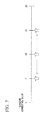
parameter adjusting unit 31 sets the default value of the correction parameter, the correctionparameter adjusting unit 31 determines the adjusting method of the correction parameter in accordance with the recognition result of theobject recognizing unit 23 when at least two correction parameters differing from each other are set.Fig. 7 is a drawing illustrating the adjusting method in the second embodiment of the present invention. In the present embodiment, to set forth simply, the default value of the correction parameter for adjusting the exposure to be used in theimage correcting unit 21b is set to "10". - As shown in
FIG. 7 , for example, after the correctionparameter adjusting unit 31 sets the default value of the correction parameter to "10", the correctionparameter adjusting unit 31 sequentially sets the correction parameter to "5" and "15" differing from the default value "10" by "5". The correctionparameter adjusting unit 31 obtains the recognition result of theobject recognizing unit 23 when the correction parameter is set to "5". Also, the correctionparameter adjusting unit 31 obtains the recognition result of theobject recognizing unit 23 when the correction parameter is set to "15". Further, the correctionparameter adjusting unit 31 determines the adjusting method of the correction parameter in accordance with the recognition results respectively. For example, the adjusting method is whether increasing the correction parameter or decreasing the correction parameter. Specifically, if a correlation value in a case of "15" is larger than a correlation value in a case of "5", the correctionparameter adjusting unit 31 determines to increase the correction parameter. - The
information display apparatus 30 differs from theinformation display apparatus 10 in setting the default value of the correction parameter to be used in theimage correcting unit 21b, and changing the adjusting method of the correction parameter in accordance with the recognition result of theobject recognizing unit 23. However, theinformation display apparatus 30 basically executes the same process of the flowchart shown inFIG. 4 . Therefore, after the process for setting the default value of the correction parameter and the process for determining the adjusting method of the correction parameter, theinformation display apparatus 30 executes the process of the flowchart shown inFIG. 4 . To avoid repeating the same explanation, a detail explanation of theinformation display apparatus 30 is left out. - As described above, in the present embodiment, the picked-up image of the
camera 11 is corrected to be suitable for displaying on thetouch panel 12, and the corrected image (image G1) is output. Also, in the present embodiment, the picked-up image of thecamera 11 is corrected to be suitable for the recognition process in theobject recognizing unit 23, and the corrected image (image G2) is output. Further, in the present embodiment, the tag information according to the recognition result of theobject recognizing unit 23 is superimposed on the image G1, and the superimposed image is displayed on thetouch panel 12. Because the image easily viewable for the worker W is displayed on thetouch panel 12 and the image suitable for image recognition is input to theobject recognizing unit 23, it is possible to improve the visibility of the image for the worker W and to improve the recognition rate. - Additionally, in the present embodiment, the default value of the correction parameter to be used in the
image correcting unit 21b is set by using the default value setting table TB. The default value setting table TB is a table in which the detection result of thesensor 13 is related to a setting value of the correction parameter when the recognition process of theobject recognizing unit 23 was successful in the past. Also, in the present embodiment, the adjusting method is determined in accordance with the recognition result of theobject recognizing unit 23. Therefore, it is possible to change the correction parameter to be used in theimage correcting unit 21 b into the exposure correction value suitable for the image recognition faster and more precisely than the first embodiment. As the result, when the marker M is taken with thecamera 11, it is possible to immediately display the tag information as the work support information on thetouch panel 12. - The
information display apparatus 10 of the first embodiment and theinformation display apparatus 30 of the second embodiment include thecamera 11 andtouch panel 12. Also, theinformation display apparatus 10 and theinformation display apparatus 30 are portable apparatuses. For example, theinformation display apparatus 10 and theinformation display apparatus 30 are portable terminals with a camera such as a smart phone, a portable phone, a game machine, a tablet terminal, and a head-mounted display. - Although an information display apparatus and an information display method according to embodiments of the present invention have been described above, the present invention is not limited to the above-described embodiments, and can be freely modified within the scope thereof. For example, although the foregoing descriptions of the embodiments have been examples in which the image display apparatus provides information by "Marker-based AR" in "Vision-based AR", the present invention is applicable to an image display apparatus for providing information by "Marker-less AR" in "Vision-based AR".
- In the embodiments described above, it is described that the work support information is the tag information. However, for example, the image display apparatus may provide helpful information for maintaining a maintenance manual of the field devices D1 to D3 with the tag information, in place of the tag information, or in relation to the tag information.
- Also, in the first and second embodiment described above, it is described that the information display apparatus displays the tag information as the work support information for supporting maintenance of the field device D1 to D3 placed in a plant. However the image display apparatus of the present invention may be adaptable to various uses such as work support in a mining site, amusement such as games, guidance in museums or event sites, medical support, or the like.
- While preferred embodiments of the invention have been described and illustrated above, it should be understood that these are exemplary of the invention and are not to be considered as limiting. Additions, omissions, substitutions, and other modifications can be made without departing from the scope of the present invention. Accordingly, the invention is not to be considered as being limited by the foregoing description, and is only limited by the scope of the appended claims.
Claims (15)
- An information display apparatus comprising:an image pick-up unit configured to picking up an image;a display unit configured to display the image picked up by the image pick-up unit;a first correcting unit configured to correct the image picked up by the image pick-up unit to generate a first image;a second correcting unit configured to correct the image picked up by the image pick-up unit to generate a second image;a recognizing unit configured to recognize the second image generated by the second correcting unit; anda display control unit configured to display an additional information according to a result of the recognition performed by the recognizing unit with superimposing the additional information on the first image generated by the first correcting unit on the display unit.
- The information display apparatus according to claim 1, wherein
the first correcting unit comprises:a sensor configured to detect brightness in photographic environments;a first adjuster configured to adjust a correction amount of the image in accordance with a result of the detection performed by the sensor; anda first corrector configured to correct the image picked up by the image pick-up unit by the correction amount adjusted by the first adjusting section. - The information display apparatus according to claim 2, wherein
the second correcting unit comprising:a second adjuster configured to adjust a correction amount of the image in accordance with whether a predetermined reference image is recognized by the recognizing unit or not;a second corrector configured to correct the image picked up by the image pick-up unit by the correction amount adjusted by the second adjuster. - The information display apparatus according to claim 3, wherein
the second adjuster section is configured to:store a table designating a relation between the detection result of the sensor and the correction amount when the reference image had been recognized by the recognizing unit,read out the correction amount according to the detection result of the sensor from the table, andset the correcting amount read out from the table as a default value of the correction amount of the image. - The information display apparatus according to claim 4, wherein
the second adjuster determines an adjusting method of the correction amount of the image in accordance with the recognition result of the recognizing unit when at least two correction amounts differing from each other are set. - The information display apparatus according to claim 1, wherein
each of the first and second correcting unit is configured to correct white balance and exposure of the image. - The information display apparatus according to claim 1, wherein
the image pick-up unit is configured to pick up an image of a field device. - The information display apparatus according to claim 7, wherein
the recognizing unit is configured to recognize a marker placed on the field device. - The information display apparatus according to claim 8, wherein
the marker comprises:a graphic for recognizing the marker; andinformation assigned uniquely to the marker. - The information display apparatus according to claim 9, wherein
the recognizing unit is configured to extract an edge of the image generated by the second correcting unit where brightness of the image generated by the second correcting unit is sharply changed at the edge. - The information display apparatus according to claim 10, wherein
the recognizing unit is configured to recognize the graphic from the edge extracted by the recognizing unit. - The information display apparatus according to claim 11, wherein
the recognizing unit is configured to compare a predetermined reference image with an image of the information assigned uniquely to the marker surrounded by the graphic recognized by the recognizing unit, and determine if the image of the information assigned uniquely to the marker matches the reference image. - The information display apparatus according to claim 7, wherein
the additional information includes work support information for supporting workers. - The information display apparatus according to claim 13, wherein
the work support information includes information for maintenance work of the field device. - An information display method comprising:picking up an image by an image pick-up unit;correcting the image picked up by the image pick-up unit to generate a first image;correcting the image picked up by the image pick-up unit to generate a second image;recognizing the second image;displaying an additional information according to a result of the recognition with superimposing the additional information on the first image on the display unit.
Applications Claiming Priority (1)
| Application Number | Priority Date | Filing Date | Title |
|---|---|---|---|
| JP2013124832A JP5786900B2 (en) | 2013-06-13 | 2013-06-13 | Information display device and information display method |
Publications (3)
| Publication Number | Publication Date |
|---|---|
| EP2814239A2 true EP2814239A2 (en) | 2014-12-17 |
| EP2814239A3 EP2814239A3 (en) | 2015-03-04 |
| EP2814239B1 EP2814239B1 (en) | 2017-08-09 |
Family
ID=50819576
Family Applications (1)
| Application Number | Title | Priority Date | Filing Date |
|---|---|---|---|
| EP14169708.6A Active EP2814239B1 (en) | 2013-06-13 | 2014-05-23 | Information display apparatus and information display method |
Country Status (5)
| Country | Link |
|---|---|
| US (1) | US9704455B2 (en) |
| EP (1) | EP2814239B1 (en) |
| JP (1) | JP5786900B2 (en) |
| CN (1) | CN104238980B (en) |
| ES (1) | ES2646605T3 (en) |
Cited By (1)
| Publication number | Priority date | Publication date | Assignee | Title |
|---|---|---|---|---|
| CN105739868A (en) * | 2016-02-01 | 2016-07-06 | 宇龙计算机通信科技(深圳)有限公司 | Method and device for identifying mistaken touch of terminal |
Families Citing this family (4)
| Publication number | Priority date | Publication date | Assignee | Title |
|---|---|---|---|---|
| JP6500355B2 (en) * | 2014-06-20 | 2019-04-17 | 富士通株式会社 | Display device, display program, and display method |
| JP6686697B2 (en) * | 2016-05-24 | 2020-04-22 | 富士通株式会社 | Transmission control program, transmission control method, and transmission control system |
| CN110750190B (en) * | 2019-10-17 | 2024-01-23 | 辽宁中航信诺科技有限公司 | Superposition method of virtual prompt information after artificial intelligent object registration and identification based on AR equipment |
| CN117156108B (en) * | 2023-10-31 | 2024-03-15 | 中海物业管理有限公司 | Enhanced display system and method for machine room equipment monitoring picture |
Citations (2)
| Publication number | Priority date | Publication date | Assignee | Title |
|---|---|---|---|---|
| JPH11234651A (en) | 1998-02-09 | 1999-08-27 | Mitsubishi Electric Corp | Supervisory camera system |
| JP2005115500A (en) | 2003-10-06 | 2005-04-28 | Mitsubishi Electric Corp | Information processing apparatus and information processing method |
Family Cites Families (20)
| Publication number | Priority date | Publication date | Assignee | Title |
|---|---|---|---|---|
| JPH09172571A (en) * | 1995-12-21 | 1997-06-30 | Sanyo Electric Co Ltd | Method for deciding camera parameter in image recognition device |
| US9183306B2 (en) * | 1998-12-18 | 2015-11-10 | Microsoft Technology Licensing, Llc | Automated selection of appropriate information based on a computer user's context |
| KR100630888B1 (en) * | 2004-11-23 | 2006-10-04 | 삼성전자주식회사 | Apparatus and Method for Improving Image Cancer Recognition Rate |
| JP4694424B2 (en) * | 2006-06-21 | 2011-06-08 | 三菱電機株式会社 | Authentication device |
| JP5119636B2 (en) * | 2006-09-27 | 2013-01-16 | ソニー株式会社 | Display device and display method |
| JP4893388B2 (en) * | 2007-03-13 | 2012-03-07 | トヨタ自動車株式会社 | Vehicle imaging device |
| US8903430B2 (en) * | 2008-02-21 | 2014-12-02 | Microsoft Corporation | Location based object tracking |
| JP2010118019A (en) * | 2008-11-14 | 2010-05-27 | Sharp Corp | Terminal device, distribution device, control method of terminal device, control method of distribution device, control program, and recording medium |
| JP5049300B2 (en) | 2009-01-20 | 2012-10-17 | クラリオン株式会社 | Obstacle detection display |
| JP5609080B2 (en) | 2009-11-30 | 2014-10-22 | 富士通株式会社 | Image processing apparatus, image display apparatus, image processing program, and image processing method |
| US8400548B2 (en) * | 2010-01-05 | 2013-03-19 | Apple Inc. | Synchronized, interactive augmented reality displays for multifunction devices |
| JP5480672B2 (en) * | 2010-03-03 | 2014-04-23 | キヤノン株式会社 | Imaging apparatus and control method thereof |
| EP2397819B1 (en) | 2010-06-21 | 2013-05-15 | Research In Motion Limited | Method, device and system for presenting navigational information |
| EP2439676A1 (en) * | 2010-10-08 | 2012-04-11 | Research in Motion Limited | System and method for displaying text in augmented reality |
| KR101714050B1 (en) | 2010-11-01 | 2017-03-08 | 삼성전자주식회사 | Device and method for displaying data in wireless terminal |
| JP5750262B2 (en) * | 2010-12-17 | 2015-07-15 | 株式会社サムスン日本研究所 | Imaging apparatus and imaging method |
| JP5014494B2 (en) * | 2011-01-21 | 2012-08-29 | パナソニック株式会社 | Information processing apparatus, augmented reality system, information processing method, and information processing program |
| US10133950B2 (en) | 2011-03-04 | 2018-11-20 | Qualcomm Incorporated | Dynamic template tracking |
| WO2014011864A1 (en) * | 2012-07-11 | 2014-01-16 | Adc Telecommunications, Inc. | Method of capturing information about a rack and equipment installed therein |
| US9094616B2 (en) * | 2012-10-16 | 2015-07-28 | Vidinoti Sa | Method and system for image capture and facilitated annotation |
-
2013
- 2013-06-13 JP JP2013124832A patent/JP5786900B2/en active Active
-
2014
- 2014-05-21 US US14/283,808 patent/US9704455B2/en active Active
- 2014-05-23 ES ES14169708.6T patent/ES2646605T3/en active Active
- 2014-05-23 EP EP14169708.6A patent/EP2814239B1/en active Active
- 2014-06-11 CN CN201410257956.XA patent/CN104238980B/en active Active
Patent Citations (2)
| Publication number | Priority date | Publication date | Assignee | Title |
|---|---|---|---|---|
| JPH11234651A (en) | 1998-02-09 | 1999-08-27 | Mitsubishi Electric Corp | Supervisory camera system |
| JP2005115500A (en) | 2003-10-06 | 2005-04-28 | Mitsubishi Electric Corp | Information processing apparatus and information processing method |
Cited By (2)
| Publication number | Priority date | Publication date | Assignee | Title |
|---|---|---|---|---|
| CN105739868A (en) * | 2016-02-01 | 2016-07-06 | 宇龙计算机通信科技(深圳)有限公司 | Method and device for identifying mistaken touch of terminal |
| CN105739868B (en) * | 2016-02-01 | 2019-05-14 | 宇龙计算机通信科技(深圳)有限公司 | A kind of method and device that identification terminal is accidentally touched |
Also Published As
| Publication number | Publication date |
|---|---|
| ES2646605T3 (en) | 2017-12-14 |
| US9704455B2 (en) | 2017-07-11 |
| EP2814239A3 (en) | 2015-03-04 |
| US20140368541A1 (en) | 2014-12-18 |
| JP2015001779A (en) | 2015-01-05 |
| JP5786900B2 (en) | 2015-09-30 |
| CN104238980B (en) | 2018-01-09 |
| CN104238980A (en) | 2014-12-24 |
| EP2814239B1 (en) | 2017-08-09 |
Similar Documents
| Publication | Publication Date | Title |
|---|---|---|
| US11138796B2 (en) | Systems and methods for contextually augmented video creation and sharing | |
| US9007400B2 (en) | Image processing device, image processing method and computer-readable medium | |
| US9704455B2 (en) | Information display apparatus and information display method for superimposing additional information on an image | |
| CN109361865B (en) | Shooting method and terminal | |
| KR101603017B1 (en) | Gesture recognition device and gesture recognition device control method | |
| US8570403B2 (en) | Face image replacement system and method implemented by portable electronic device | |
| RU2015111261A (en) | LIGHT SOURCE MANAGEMENT THROUGH A PORTABLE DEVICE | |
| EP2775374A2 (en) | User interface and method | |
| JP2017162103A (en) | Inspection work support system, inspection work support method, and inspection work support program | |
| CN115917588B (en) | Method for providing filter and electronic device supporting the method | |
| US10750080B2 (en) | Information processing device, information processing method, and program | |
| JP2017037434A (en) | Mark processing device, program | |
| US20120098967A1 (en) | 3d image monitoring system and method implemented by portable electronic device | |
| US8842202B2 (en) | Mobile terminal, method for adjusting magnification of camera and program | |
| US11417267B2 (en) | Electronic device for controlling display of content on basis of brightness information and operation method therefor | |
| CN108234978B (en) | A kind of image processing method and mobile terminal | |
| KR101908991B1 (en) | Apparatus for implementing augmented reality | |
| KR101488647B1 (en) | Virtual illumination of operating method and apparatus for mobile terminal | |
| JP2016139342A (en) | Information input method by device cooperation, information processing device, computer program | |
| KR20200093760A (en) | Electronic device having a plurality of lens and controlling method thereof | |
| KR102852066B1 (en) | Method, apparatus, computer-readable storage medium and computer program for processing data | |
| CN111492646B (en) | Electronic equipment and method of operation thereof | |
| JP2017049680A (en) | Object indication system, object indication method, and program | |
| WO2020137197A1 (en) | Information processing device, information processing method, and information processing program | |
| JP2016111521A (en) | Information processing device, information processing program and information processing method |
Legal Events
| Date | Code | Title | Description |
|---|---|---|---|
| 17P | Request for examination filed |
Effective date: 20140523 |
|
| AK | Designated contracting states |
Kind code of ref document: A2 Designated state(s): AL AT BE BG CH CY CZ DE DK EE ES FI FR GB GR HR HU IE IS IT LI LT LU LV MC MK MT NL NO PL PT RO RS SE SI SK SM TR |
|
| AX | Request for extension of the european patent |
Extension state: BA ME |
|
| PUAI | Public reference made under article 153(3) epc to a published international application that has entered the european phase |
Free format text: ORIGINAL CODE: 0009012 |
|
| PUAL | Search report despatched |
Free format text: ORIGINAL CODE: 0009013 |
|
| AK | Designated contracting states |
Kind code of ref document: A3 Designated state(s): AL AT BE BG CH CY CZ DE DK EE ES FI FR GB GR HR HU IE IS IT LI LT LU LV MC MK MT NL NO PL PT RO RS SE SI SK SM TR |
|
| AX | Request for extension of the european patent |
Extension state: BA ME |
|
| RIC1 | Information provided on ipc code assigned before grant |
Ipc: G09B 5/06 20060101ALI20150129BHEP Ipc: G06K 9/00 20060101ALI20150129BHEP Ipc: G09G 5/377 20060101ALI20150129BHEP Ipc: H04N 5/232 20060101AFI20150129BHEP Ipc: G06F 3/01 20060101ALI20150129BHEP |
|
| R17P | Request for examination filed (corrected) |
Effective date: 20150831 |
|
| RBV | Designated contracting states (corrected) |
Designated state(s): AL AT BE BG CH CY CZ DE DK EE ES FI FR GB GR HR HU IE IS IT LI LT LU LV MC MK MT NL NO PL PT RO RS SE SI SK SM TR |
|
| 17Q | First examination report despatched |
Effective date: 20151109 |
|
| REG | Reference to a national code |
Ref country code: DE Ref legal event code: R079 Ref document number: 602014012750 Country of ref document: DE Free format text: PREVIOUS MAIN CLASS: H04N0005232000 Ipc: H04N0009730000 |
|
| GRAP | Despatch of communication of intention to grant a patent |
Free format text: ORIGINAL CODE: EPIDOSNIGR1 |
|
| RIC1 | Information provided on ipc code assigned before grant |
Ipc: H04N 9/73 20060101AFI20170306BHEP Ipc: H04N 5/232 20060101ALI20170306BHEP Ipc: G06F 3/0484 20130101ALI20170306BHEP Ipc: G09G 5/377 20060101ALI20170306BHEP Ipc: G06F 3/0488 20130101ALI20170306BHEP Ipc: G06T 5/00 20060101ALI20170306BHEP Ipc: G06K 9/00 20060101ALI20170306BHEP |
|
| INTG | Intention to grant announced |
Effective date: 20170320 |
|
| GRAS | Grant fee paid |
Free format text: ORIGINAL CODE: EPIDOSNIGR3 |
|
| GRAA | (expected) grant |
Free format text: ORIGINAL CODE: 0009210 |
|
| AK | Designated contracting states |
Kind code of ref document: B1 Designated state(s): AL AT BE BG CH CY CZ DE DK EE ES FI FR GB GR HR HU IE IS IT LI LT LU LV MC MK MT NL NO PL PT RO RS SE SI SK SM TR |
|
| REG | Reference to a national code |
Ref country code: GB Ref legal event code: FG4D |
|
| REG | Reference to a national code |
Ref country code: CH Ref legal event code: EP Ref country code: AT Ref legal event code: REF Ref document number: 918005 Country of ref document: AT Kind code of ref document: T Effective date: 20170815 |
|
| REG | Reference to a national code |
Ref country code: IE Ref legal event code: FG4D |
|
| REG | Reference to a national code |
Ref country code: DE Ref legal event code: R096 Ref document number: 602014012750 Country of ref document: DE |
|
| REG | Reference to a national code |
Ref country code: NL Ref legal event code: FP |
|
| REG | Reference to a national code |
Ref country code: ES Ref legal event code: FG2A Ref document number: 2646605 Country of ref document: ES Kind code of ref document: T3 Effective date: 20171214 |
|
| REG | Reference to a national code |
Ref country code: LT Ref legal event code: MG4D |
|
| REG | Reference to a national code |
Ref country code: AT Ref legal event code: MK05 Ref document number: 918005 Country of ref document: AT Kind code of ref document: T Effective date: 20170809 |
|
| PG25 | Lapsed in a contracting state [announced via postgrant information from national office to epo] |
Ref country code: LT Free format text: LAPSE BECAUSE OF FAILURE TO SUBMIT A TRANSLATION OF THE DESCRIPTION OR TO PAY THE FEE WITHIN THE PRESCRIBED TIME-LIMIT Effective date: 20170809 Ref country code: HR Free format text: LAPSE BECAUSE OF FAILURE TO SUBMIT A TRANSLATION OF THE DESCRIPTION OR TO PAY THE FEE WITHIN THE PRESCRIBED TIME-LIMIT Effective date: 20170809 Ref country code: FI Free format text: LAPSE BECAUSE OF FAILURE TO SUBMIT A TRANSLATION OF THE DESCRIPTION OR TO PAY THE FEE WITHIN THE PRESCRIBED TIME-LIMIT Effective date: 20170809 Ref country code: AT Free format text: LAPSE BECAUSE OF FAILURE TO SUBMIT A TRANSLATION OF THE DESCRIPTION OR TO PAY THE FEE WITHIN THE PRESCRIBED TIME-LIMIT Effective date: 20170809 Ref country code: SE Free format text: LAPSE BECAUSE OF FAILURE TO SUBMIT A TRANSLATION OF THE DESCRIPTION OR TO PAY THE FEE WITHIN THE PRESCRIBED TIME-LIMIT Effective date: 20170809 Ref country code: NO Free format text: LAPSE BECAUSE OF FAILURE TO SUBMIT A TRANSLATION OF THE DESCRIPTION OR TO PAY THE FEE WITHIN THE PRESCRIBED TIME-LIMIT Effective date: 20171109 |
|
| PG25 | Lapsed in a contracting state [announced via postgrant information from national office to epo] |
Ref country code: GR Free format text: LAPSE BECAUSE OF FAILURE TO SUBMIT A TRANSLATION OF THE DESCRIPTION OR TO PAY THE FEE WITHIN THE PRESCRIBED TIME-LIMIT Effective date: 20171110 Ref country code: PL Free format text: LAPSE BECAUSE OF FAILURE TO SUBMIT A TRANSLATION OF THE DESCRIPTION OR TO PAY THE FEE WITHIN THE PRESCRIBED TIME-LIMIT Effective date: 20170809 Ref country code: BG Free format text: LAPSE BECAUSE OF FAILURE TO SUBMIT A TRANSLATION OF THE DESCRIPTION OR TO PAY THE FEE WITHIN THE PRESCRIBED TIME-LIMIT Effective date: 20171109 Ref country code: LV Free format text: LAPSE BECAUSE OF FAILURE TO SUBMIT A TRANSLATION OF THE DESCRIPTION OR TO PAY THE FEE WITHIN THE PRESCRIBED TIME-LIMIT Effective date: 20170809 Ref country code: IS Free format text: LAPSE BECAUSE OF FAILURE TO SUBMIT A TRANSLATION OF THE DESCRIPTION OR TO PAY THE FEE WITHIN THE PRESCRIBED TIME-LIMIT Effective date: 20171209 Ref country code: RS Free format text: LAPSE BECAUSE OF FAILURE TO SUBMIT A TRANSLATION OF THE DESCRIPTION OR TO PAY THE FEE WITHIN THE PRESCRIBED TIME-LIMIT Effective date: 20170809 |
|
| REG | Reference to a national code |
Ref country code: FR Ref legal event code: PLFP Year of fee payment: 5 |
|
| PG25 | Lapsed in a contracting state [announced via postgrant information from national office to epo] |
Ref country code: CZ Free format text: LAPSE BECAUSE OF FAILURE TO SUBMIT A TRANSLATION OF THE DESCRIPTION OR TO PAY THE FEE WITHIN THE PRESCRIBED TIME-LIMIT Effective date: 20170809 Ref country code: RO Free format text: LAPSE BECAUSE OF FAILURE TO SUBMIT A TRANSLATION OF THE DESCRIPTION OR TO PAY THE FEE WITHIN THE PRESCRIBED TIME-LIMIT Effective date: 20170809 Ref country code: DK Free format text: LAPSE BECAUSE OF FAILURE TO SUBMIT A TRANSLATION OF THE DESCRIPTION OR TO PAY THE FEE WITHIN THE PRESCRIBED TIME-LIMIT Effective date: 20170809 |
|
| REG | Reference to a national code |
Ref country code: DE Ref legal event code: R097 Ref document number: 602014012750 Country of ref document: DE |
|
| PG25 | Lapsed in a contracting state [announced via postgrant information from national office to epo] |
Ref country code: SK Free format text: LAPSE BECAUSE OF FAILURE TO SUBMIT A TRANSLATION OF THE DESCRIPTION OR TO PAY THE FEE WITHIN THE PRESCRIBED TIME-LIMIT Effective date: 20170809 Ref country code: IT Free format text: LAPSE BECAUSE OF FAILURE TO SUBMIT A TRANSLATION OF THE DESCRIPTION OR TO PAY THE FEE WITHIN THE PRESCRIBED TIME-LIMIT Effective date: 20170809 Ref country code: SM Free format text: LAPSE BECAUSE OF FAILURE TO SUBMIT A TRANSLATION OF THE DESCRIPTION OR TO PAY THE FEE WITHIN THE PRESCRIBED TIME-LIMIT Effective date: 20170809 Ref country code: EE Free format text: LAPSE BECAUSE OF FAILURE TO SUBMIT A TRANSLATION OF THE DESCRIPTION OR TO PAY THE FEE WITHIN THE PRESCRIBED TIME-LIMIT Effective date: 20170809 |
|
| PLBE | No opposition filed within time limit |
Free format text: ORIGINAL CODE: 0009261 |
|
| STAA | Information on the status of an ep patent application or granted ep patent |
Free format text: STATUS: NO OPPOSITION FILED WITHIN TIME LIMIT |
|
| 26N | No opposition filed |
Effective date: 20180511 |
|
| PG25 | Lapsed in a contracting state [announced via postgrant information from national office to epo] |
Ref country code: SI Free format text: LAPSE BECAUSE OF FAILURE TO SUBMIT A TRANSLATION OF THE DESCRIPTION OR TO PAY THE FEE WITHIN THE PRESCRIBED TIME-LIMIT Effective date: 20170809 |
|
| REG | Reference to a national code |
Ref country code: CH Ref legal event code: PL |
|
| PG25 | Lapsed in a contracting state [announced via postgrant information from national office to epo] |
Ref country code: MC Free format text: LAPSE BECAUSE OF FAILURE TO SUBMIT A TRANSLATION OF THE DESCRIPTION OR TO PAY THE FEE WITHIN THE PRESCRIBED TIME-LIMIT Effective date: 20170809 |
|
| REG | Reference to a national code |
Ref country code: IE Ref legal event code: MM4A |
|
| PG25 | Lapsed in a contracting state [announced via postgrant information from national office to epo] |
Ref country code: LI Free format text: LAPSE BECAUSE OF NON-PAYMENT OF DUE FEES Effective date: 20180531 Ref country code: CH Free format text: LAPSE BECAUSE OF NON-PAYMENT OF DUE FEES Effective date: 20180531 |
|
| PG25 | Lapsed in a contracting state [announced via postgrant information from national office to epo] |
Ref country code: LU Free format text: LAPSE BECAUSE OF NON-PAYMENT OF DUE FEES Effective date: 20180523 |
|
| PG25 | Lapsed in a contracting state [announced via postgrant information from national office to epo] |
Ref country code: IE Free format text: LAPSE BECAUSE OF NON-PAYMENT OF DUE FEES Effective date: 20180523 |
|
| PG25 | Lapsed in a contracting state [announced via postgrant information from national office to epo] |
Ref country code: MT Free format text: LAPSE BECAUSE OF NON-PAYMENT OF DUE FEES Effective date: 20180523 |
|
| PG25 | Lapsed in a contracting state [announced via postgrant information from national office to epo] |
Ref country code: TR Free format text: LAPSE BECAUSE OF FAILURE TO SUBMIT A TRANSLATION OF THE DESCRIPTION OR TO PAY THE FEE WITHIN THE PRESCRIBED TIME-LIMIT Effective date: 20170809 |
|
| PG25 | Lapsed in a contracting state [announced via postgrant information from national office to epo] |
Ref country code: PT Free format text: LAPSE BECAUSE OF FAILURE TO SUBMIT A TRANSLATION OF THE DESCRIPTION OR TO PAY THE FEE WITHIN THE PRESCRIBED TIME-LIMIT Effective date: 20170809 Ref country code: HU Free format text: LAPSE BECAUSE OF FAILURE TO SUBMIT A TRANSLATION OF THE DESCRIPTION OR TO PAY THE FEE WITHIN THE PRESCRIBED TIME-LIMIT; INVALID AB INITIO Effective date: 20140523 |
|
| PG25 | Lapsed in a contracting state [announced via postgrant information from national office to epo] |
Ref country code: CY Free format text: LAPSE BECAUSE OF FAILURE TO SUBMIT A TRANSLATION OF THE DESCRIPTION OR TO PAY THE FEE WITHIN THE PRESCRIBED TIME-LIMIT Effective date: 20170809 Ref country code: MK Free format text: LAPSE BECAUSE OF NON-PAYMENT OF DUE FEES Effective date: 20170809 |
|
| PG25 | Lapsed in a contracting state [announced via postgrant information from national office to epo] |
Ref country code: AL Free format text: LAPSE BECAUSE OF FAILURE TO SUBMIT A TRANSLATION OF THE DESCRIPTION OR TO PAY THE FEE WITHIN THE PRESCRIBED TIME-LIMIT Effective date: 20170809 |
|
| REG | Reference to a national code |
Ref country code: FR Ref legal event code: PLFP Year of fee payment: 10 |
|
| PGFP | Annual fee paid to national office [announced via postgrant information from national office to epo] |
Ref country code: GB Payment date: 20230330 Year of fee payment: 10 |
|
| PGFP | Annual fee paid to national office [announced via postgrant information from national office to epo] |
Ref country code: NL Payment date: 20230417 Year of fee payment: 10 |
|
| P01 | Opt-out of the competence of the unified patent court (upc) registered |
Effective date: 20230603 |
|
| PGFP | Annual fee paid to national office [announced via postgrant information from national office to epo] |
Ref country code: FR Payment date: 20230411 Year of fee payment: 10 Ref country code: ES Payment date: 20230601 Year of fee payment: 10 |
|
| PGFP | Annual fee paid to national office [announced via postgrant information from national office to epo] |
Ref country code: BE Payment date: 20230418 Year of fee payment: 10 |
|
| REG | Reference to a national code |
Ref country code: NL Ref legal event code: MM Effective date: 20240601 |
|
| GBPC | Gb: european patent ceased through non-payment of renewal fee |
Effective date: 20240523 |
|
| PG25 | Lapsed in a contracting state [announced via postgrant information from national office to epo] |
Ref country code: NL Free format text: LAPSE BECAUSE OF NON-PAYMENT OF DUE FEES Effective date: 20240601 |
|
| REG | Reference to a national code |
Ref country code: BE Ref legal event code: MM Effective date: 20240531 |
|
| PG25 | Lapsed in a contracting state [announced via postgrant information from national office to epo] |
Ref country code: BE Free format text: LAPSE BECAUSE OF NON-PAYMENT OF DUE FEES Effective date: 20240531 |
|
| PG25 | Lapsed in a contracting state [announced via postgrant information from national office to epo] |
Ref country code: FR Free format text: LAPSE BECAUSE OF NON-PAYMENT OF DUE FEES Effective date: 20240531 |
|
| PG25 | Lapsed in a contracting state [announced via postgrant information from national office to epo] |
Ref country code: GB Free format text: LAPSE BECAUSE OF NON-PAYMENT OF DUE FEES Effective date: 20240523 |
|
| REG | Reference to a national code |
Ref country code: ES Ref legal event code: FD2A Effective date: 20250704 |
|
| PGFP | Annual fee paid to national office [announced via postgrant information from national office to epo] |
Ref country code: DE Payment date: 20250423 Year of fee payment: 12 |
|
| PG25 | Lapsed in a contracting state [announced via postgrant information from national office to epo] |
Ref country code: ES Free format text: LAPSE BECAUSE OF NON-PAYMENT OF DUE FEES Effective date: 20240524 |