EP2814232A1 - Image reading device and image forming apparatus including the same - Google Patents
Image reading device and image forming apparatus including the same Download PDFInfo
- Publication number
- EP2814232A1 EP2814232A1 EP14171902.1A EP14171902A EP2814232A1 EP 2814232 A1 EP2814232 A1 EP 2814232A1 EP 14171902 A EP14171902 A EP 14171902A EP 2814232 A1 EP2814232 A1 EP 2814232A1
- Authority
- EP
- European Patent Office
- Prior art keywords
- light
- original
- guiding member
- long
- reading device
- Prior art date
- Legal status (The legal status is an assumption and is not a legal conclusion. Google has not performed a legal analysis and makes no representation as to the accuracy of the status listed.)
- Withdrawn
Links
- 230000003287 optical effect Effects 0.000 claims abstract description 49
- 238000003825 pressing Methods 0.000 claims description 8
- 238000003384 imaging method Methods 0.000 claims description 7
- 238000009826 distribution Methods 0.000 description 21
- 230000000052 comparative effect Effects 0.000 description 16
- 230000000694 effects Effects 0.000 description 9
- 238000010586 diagram Methods 0.000 description 6
- 239000000758 substrate Substances 0.000 description 6
- 238000005549 size reduction Methods 0.000 description 5
- 238000009434 installation Methods 0.000 description 4
- 239000011521 glass Substances 0.000 description 3
- 238000012986 modification Methods 0.000 description 3
- 230000004048 modification Effects 0.000 description 3
- 239000011347 resin Substances 0.000 description 3
- 229920005989 resin Polymers 0.000 description 3
- 230000002411 adverse Effects 0.000 description 2
- 239000000463 material Substances 0.000 description 2
- 238000005299 abrasion Methods 0.000 description 1
- 238000005520 cutting process Methods 0.000 description 1
Images




Classifications
-
- H—ELECTRICITY
- H04—ELECTRIC COMMUNICATION TECHNIQUE
- H04N—PICTORIAL COMMUNICATION, e.g. TELEVISION
- H04N1/00—Scanning, transmission or reproduction of documents or the like, e.g. facsimile transmission; Details thereof
- H04N1/024—Details of scanning heads ; Means for illuminating the original
- H04N1/028—Details of scanning heads ; Means for illuminating the original for picture information pick-up
- H04N1/02815—Means for illuminating the original, not specific to a particular type of pick-up head
- H04N1/02885—Means for compensating spatially uneven illumination, e.g. an aperture arrangement
-
- H—ELECTRICITY
- H04—ELECTRIC COMMUNICATION TECHNIQUE
- H04N—PICTORIAL COMMUNICATION, e.g. TELEVISION
- H04N1/00—Scanning, transmission or reproduction of documents or the like, e.g. facsimile transmission; Details thereof
- H04N1/024—Details of scanning heads ; Means for illuminating the original
- H04N1/028—Details of scanning heads ; Means for illuminating the original for picture information pick-up
-
- H—ELECTRICITY
- H04—ELECTRIC COMMUNICATION TECHNIQUE
- H04N—PICTORIAL COMMUNICATION, e.g. TELEVISION
- H04N1/00—Scanning, transmission or reproduction of documents or the like, e.g. facsimile transmission; Details thereof
- H04N1/00795—Reading arrangements
- H04N1/00827—Arrangements for reading an image from an unusual original, e.g. 3-dimensional objects
-
- H—ELECTRICITY
- H04—ELECTRIC COMMUNICATION TECHNIQUE
- H04N—PICTORIAL COMMUNICATION, e.g. TELEVISION
- H04N1/00—Scanning, transmission or reproduction of documents or the like, e.g. facsimile transmission; Details thereof
- H04N1/024—Details of scanning heads ; Means for illuminating the original
- H04N1/028—Details of scanning heads ; Means for illuminating the original for picture information pick-up
- H04N1/0281—Details of scanning heads ; Means for illuminating the original for picture information pick-up with means for collecting light from a line or an area of the original and for guiding it to only one or a relatively low number of picture element detectors
-
- H—ELECTRICITY
- H04—ELECTRIC COMMUNICATION TECHNIQUE
- H04N—PICTORIAL COMMUNICATION, e.g. TELEVISION
- H04N1/00—Scanning, transmission or reproduction of documents or the like, e.g. facsimile transmission; Details thereof
- H04N1/024—Details of scanning heads ; Means for illuminating the original
- H04N1/028—Details of scanning heads ; Means for illuminating the original for picture information pick-up
- H04N1/02815—Means for illuminating the original, not specific to a particular type of pick-up head
- H04N1/0282—Using a single or a few point light sources, e.g. a laser diode
- H04N1/02825—Using a single or a few point light sources, e.g. a laser diode in combination with at least one reflector which is fixed in relation to the light source
-
- H—ELECTRICITY
- H04—ELECTRIC COMMUNICATION TECHNIQUE
- H04N—PICTORIAL COMMUNICATION, e.g. TELEVISION
- H04N1/00—Scanning, transmission or reproduction of documents or the like, e.g. facsimile transmission; Details thereof
- H04N1/024—Details of scanning heads ; Means for illuminating the original
- H04N1/028—Details of scanning heads ; Means for illuminating the original for picture information pick-up
- H04N1/02815—Means for illuminating the original, not specific to a particular type of pick-up head
- H04N1/0282—Using a single or a few point light sources, e.g. a laser diode
- H04N1/02835—Using a single or a few point light sources, e.g. a laser diode in combination with a light guide, e.g. optical fibre, glass plate
-
- H—ELECTRICITY
- H04—ELECTRIC COMMUNICATION TECHNIQUE
- H04N—PICTORIAL COMMUNICATION, e.g. TELEVISION
- H04N1/00—Scanning, transmission or reproduction of documents or the like, e.g. facsimile transmission; Details thereof
- H04N1/024—Details of scanning heads ; Means for illuminating the original
- H04N1/028—Details of scanning heads ; Means for illuminating the original for picture information pick-up
- H04N1/02815—Means for illuminating the original, not specific to a particular type of pick-up head
- H04N1/0282—Using a single or a few point light sources, e.g. a laser diode
- H04N1/0284—Using a single or a few point light sources, e.g. a laser diode in combination with a light integrating, concentrating or diffusing cavity
-
- H—ELECTRICITY
- H04—ELECTRIC COMMUNICATION TECHNIQUE
- H04N—PICTORIAL COMMUNICATION, e.g. TELEVISION
- H04N1/00—Scanning, transmission or reproduction of documents or the like, e.g. facsimile transmission; Details thereof
- H04N1/024—Details of scanning heads ; Means for illuminating the original
- H04N1/028—Details of scanning heads ; Means for illuminating the original for picture information pick-up
- H04N1/02815—Means for illuminating the original, not specific to a particular type of pick-up head
- H04N1/02845—Means for illuminating the original, not specific to a particular type of pick-up head using an elongated light source, e.g. tubular lamp, LED array
- H04N1/0285—Means for illuminating the original, not specific to a particular type of pick-up head using an elongated light source, e.g. tubular lamp, LED array in combination with at least one reflector which is in fixed relation to the light source
-
- H—ELECTRICITY
- H04—ELECTRIC COMMUNICATION TECHNIQUE
- H04N—PICTORIAL COMMUNICATION, e.g. TELEVISION
- H04N1/00—Scanning, transmission or reproduction of documents or the like, e.g. facsimile transmission; Details thereof
- H04N1/024—Details of scanning heads ; Means for illuminating the original
- H04N1/028—Details of scanning heads ; Means for illuminating the original for picture information pick-up
- H04N1/02815—Means for illuminating the original, not specific to a particular type of pick-up head
- H04N1/02885—Means for compensating spatially uneven illumination, e.g. an aperture arrangement
- H04N1/0289—Light diffusing elements, e.g. plates or filters
-
- H—ELECTRICITY
- H04—ELECTRIC COMMUNICATION TECHNIQUE
- H04N—PICTORIAL COMMUNICATION, e.g. TELEVISION
- H04N1/00—Scanning, transmission or reproduction of documents or the like, e.g. facsimile transmission; Details thereof
- H04N1/024—Details of scanning heads ; Means for illuminating the original
- H04N1/028—Details of scanning heads ; Means for illuminating the original for picture information pick-up
- H04N1/02815—Means for illuminating the original, not specific to a particular type of pick-up head
- H04N1/02895—Additional elements in the illumination means or cooperating with the illumination means, e.g. filters
-
- H—ELECTRICITY
- H04—ELECTRIC COMMUNICATION TECHNIQUE
- H04N—PICTORIAL COMMUNICATION, e.g. TELEVISION
- H04N1/00—Scanning, transmission or reproduction of documents or the like, e.g. facsimile transmission; Details thereof
- H04N1/04—Scanning arrangements, i.e. arrangements for the displacement of active reading or reproducing elements relative to the original or reproducing medium, or vice versa
-
- H—ELECTRICITY
- H04—ELECTRIC COMMUNICATION TECHNIQUE
- H04N—PICTORIAL COMMUNICATION, e.g. TELEVISION
- H04N1/00—Scanning, transmission or reproduction of documents or the like, e.g. facsimile transmission; Details thereof
- H04N1/04—Scanning arrangements, i.e. arrangements for the displacement of active reading or reproducing elements relative to the original or reproducing medium, or vice versa
- H04N1/10—Scanning arrangements, i.e. arrangements for the displacement of active reading or reproducing elements relative to the original or reproducing medium, or vice versa using flat picture-bearing surfaces
-
- H—ELECTRICITY
- H04—ELECTRIC COMMUNICATION TECHNIQUE
- H04N—PICTORIAL COMMUNICATION, e.g. TELEVISION
- H04N2201/00—Indexing scheme relating to scanning, transmission or reproduction of documents or the like, and to details thereof
- H04N2201/04—Scanning arrangements
- H04N2201/0402—Arrangements not specific to a particular one of the scanning methods covered by groups H04N1/04 - H04N1/207
- H04N2201/0432—Adjusting the orientation of the scanning elements relative to the scanned sheet, e.g. changing from longitudinal to lateral scanning
Definitions
- the present invention relates to an image reading device and is suitable for a digital copying machine, an image scanner, and the like.
- Illuminating units included in known image reading devices employ light-emitting diodes (hereinafter abbreviated to LEDs) that are highly durable and highly efficient in light utilization.
- An image reading device disclosed by Japanese Patent Laid-Open No. 2012-160940 employs an illuminating unit including LED light sources that are provided at two respective long-side ends of a light-guiding member (the type of such an illuminating unit is hereinafter referred to as two-end source type), whereby the illuminance is increased and the nonuniformity in illuminance is reduced.
- the illuminating unit of the two-end source type disclosed by Japanese Patent Laid-Open No. 2012-160940 needs to include spaces for providing the light sources at the two respective ends of the light-guiding member. Therefore, the size of such an image reading device tends to be large.
- the present invention provides a compact image reading device and a compact image forming apparatus.
- the present invention in its first aspect provides an image reading device as specified in claims 1 to 8.
- the present invention in its second aspect provides an image forming apparatus as specified in claims 9 and 10.
- the present invention in its third aspect provides an image reading device as specified in claims 11 to 15.
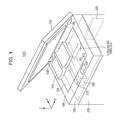
- Fig. 1 is a schematic diagram illustrating major elements of an image forming apparatus 1000 according to a general embodiment of the present invention that includes an image reading device 100 and an image forming device 200.
- a user can give instructions to the image forming apparatus 1000 by using an operation portion 102 while checking information displayed on a display portion 101.
- the image reading device 100 according to the general embodiment is capable of reading an A3-size original and has a reading area (an illuminated area) of about 300 mm x 420 mm.
- the image reading device 100 includes a platen 104 on which an original 103 is to be placed, an original pressing plate 105 configured to press the original 103 against the platen 104, a holding portion 108 configured to hold the platen 104, and a carriage 300 provided below the platen 104.
- the platen 104 is made of glass
- the original pressing plate 105 is attached to the holding portion 108 with hinge portions 106
- the carriage 300 is capable of scanning the original 103 while moving in an X direction (a subscanning direction).
- Fig. 2 is a sectional view of the carriage 300 taken along a Z-X plane.
- the carriage 300 includes a housing 301, an illuminating unit 310 configured to illuminate the original 103, a linear sensor 304 configured to receive light from the original 103, an optical unit 303 configured to guide the light from the original 103 to the linear sensor 304, and a plurality of mirrors 302 that reflect the light from the original 103 and are provided in an optical path between the original 103 and the optical unit 303.
- the optical unit 303 is a reduction imaging system
- the linear sensor 304 is a line sensor (including pixels that are arranged one-dimensionally in a Y direction) extending in the Y direction (a direction perpendicular to the page surface).
- An image of the original 103 that is formed on the linear sensor 304 is transmitted as one-dimensional image information to a controller 305.
- the controller 305 receives a piece of one-dimensional image information every time the carriage 300 reads the original 103, thereby acquiring two-dimensional image information including a plurality of pieces of one-dimensional image information. Furthermore, the controller 305 corrects pieces of information on the color, contrast, and so forth of the image, converts the corrected pieces of information into signals, and transmits the signals to the image forming device 200.
- the image forming device 200 forms an image on a recording medium such as paper in an electrophotographic manner, an inkjet manner, or the like in accordance with the signals received from the controller 305.
- the illuminating unit 310 includes a light-guiding member extending in a long-side direction of the linear sensor 304, and a light source provided only at one long-side end of the light-guiding member. Therefore, the image reading device 100 can have a smaller size and requires a smaller area of installation than the illuminating unit of the two-end source type. Furthermore, the image reading device 100 according to the general embodiment includes an aligning portion with reference to which the position of the original 103 in the long-side direction of the linear sensor 304 (the long-side direction of the light-guiding member) is determined. The aligning portion is provided on a side opposite the light source in the long-side direction of the light-guiding member.
- the image reading device 100 according to the general embodiment will further be described as more specific embodiments.
- FIG. 3 is a schematic diagram (a sectional view taken along a Y-Z plane) illustrating major elements of the image reading device 100 according to the first embodiment.
- An illuminating unit 310 according to the first embodiment includes a light source (LED) 312 mounted on a substrate 313, a light-guiding member 311 having a plane of incidence on a side thereof facing the light source 312, and a heat sink 314 provided on the back side of the substrate 313 (on a side opposite the side on which the light source 312 is mounted) and that exhausts heat generated from the light source 312.
- the long-side direction of the light-guiding member 311 corresponds to the Y direction (a main scanning direction).
- the illuminating unit 310 employs a configuration in which the light source 312 is provided only at one long-side end (a -Y-side end) of the light-guiding member 311 (such a configuration is hereinafter referred to as one-end source type).
- the one-end source type the other long-side end (a +Y-side end) of the light-guiding member 311 is provided with no light source, substrate, or heat sink. Therefore, the length of the holding portion 108 in the Y direction can be made smaller than in the two-end source type.
- the image reading device 100 can have a small size.
- the light-guiding member 311 has, at the bottom thereof, an optical surface (a secondary light-source surface) 315 in which a plurality of microscopic prisms (a group of secondary light sources) are aligned in the Y direction.
- the optical surface 315 behaves like a light source that emits light by itself. Such a behavior is based on total reflection. Accordingly, the light emitted from the optical surface 315 is characterized in traveling with an angular distribution deviating in a direction away from the light source 312 (such a characteristic is hereinafter referred to as deviation characteristic).
- the light reflected by the optical surface 315 has a deviation characteristic of traveling only toward a +Y side. The present inventor has focused on such a deviation characteristic observed in the one-end source type and has found that effects produced by providing the microscopic prisms are reduced near the +Y-side end of the light-guiding member 311.
- a portion of the bottom surface thereof at the end on the side (the +Y side) opposite the light source 312 has no microscopic prisms. Furthermore, in the long-side direction of the light-guiding member 311 (the Y direction), the distance between a center axis 321 of the optical surface 315 and the light source 312 is shorter than the distance between an optical axis 306 defined by the optical unit 303 and the light source 312. That is, the center axis 321 of the optical surface 315 is intentionally shifted toward the light source 312 with respect to the optical axis 306 of the optical unit 303. With such a configuration, the size of the light-guiding member 311 is reduced.
- the area of a mold that is to be processed for forming the light-guiding member 311 having the microscopic prisms from resin is reduced. Therefore, the abrasion of a cutting tool is suppressed, and the light-guiding member 311 is formed with high accuracy and at a low cost.
- the depth of field is larger than that of a device of a contact-image-sensor type that employs a 1x-magnification optical system.
- the illuminating unit 310 On the platen 104 (at a height of an illuminated surface of 0 mm), the illuminating unit 310 substantially uniformly illuminates the entirety of an area extending from the end on the side (the -Y side) nearer to the light source 312 to the end on the side (the +Y side) opposite the light source 312. As described above, however, the light reflected by the optical surface 315 has a deviation characteristic of traveling only toward the +Y side. Hence, as the height of the illuminated surface increases, the distribution of the quantity of illuminating light deviates toward the side (+Y side) opposite the light source 312. That is, because of the above deviation characteristic, the quantity of illuminating light on the side nearer to the light source 312 in the Y direction is significantly reduced with the increase in the height of the illuminated surface.
- the first embodiment employs a configuration in which an aligning portion 307 with reference to which the position of the original 103 in the Y direction is determined is provided at a position corresponding to the end of the light-guiding member 311 that is on the side (+Y side) opposite the light source 312 in the Y direction.
- the original 103 is positioned away from a side of the platen 104 that is nearer to the light source 312 in the Y direction. Therefore, in combination with the deviation characteristic observed in the one-end source type, the quantity of light is maintained to be substantially constant even if the height of the illuminated surface changes. That is, even if the original 103 is lifted from the platen 104, the uniformity in the illuminance of the light applied to the original 103 is maintained.
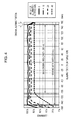
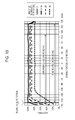
- Fig. 4 is a graph illustrating illuminance distributions that are observed when light is emitted from the light source 312 provided at one end of the light-guiding member 311 of the image reading device 100 according to the first embodiment.
- the horizontal axis represents the reading position in the Y direction (the main-scan reading position)
- the vertical axis represents the illuminance ratio (the relative value of illuminance with the peak value being 100%) of the light received by the linear sensor 304.
- the curves represent illuminance distributions observed with respective amounts of lifting of the surface of the original 103 (at respective heights of the illuminated surface) from the platen 104.
- the original 103 is positioned within the reading area (an area to be illuminated by the illuminating unit 310) on the platen 104.
- Such a reduction imaging method has a problem in that the quantity of light received at an end of the linear sensor 304 is reduced because of the field-angle characteristic (the cosine-fourth-power law) of the optical unit 303 even if the original 103 is not lifted.
- the microscopic prisms are provided appropriately in the light-guiding member 311, whereby the illuminance ratio at a height of the illuminated surface of 0 mm is made substantially uniform over the entirety of the reading area as graphed in Fig. 4 .
- the illuminance ratio at one end (the -Y-side end) of the reading area is reduced.
- the illuminance ratio at the -Y-side end of the reading area is reduced to about 20%.
- the bound portion of a thick original, such as a dictionary tends to reside at a large height.
- the lengths of many such originals in the Y direction are about 260 mm.
- a main original area represented in Fig. 4 is to be read.
- the illuminance ratio is substantially uniform over the entirety of the main original area at any height of the illuminated surface.
- the aligning portion 307 is provided on the other end (the +Y-side end) of the reading area, i.e., the side opposite the light source 312, the influence of the reduction in the illuminance ratio at the -Y-side end is avoided.
- the aligning portion 307 is provided on the holding portion 108.
- the aligning portion 307 may be provided at any other position, for example, a position on the platen 104, as long as the position of the original 103 in the Y direction is determinable.
- the aligning portion 307 is provided such that a surface (an aligning surface) thereof with which the original 103 comes into contact extends in a direction (the X direction) perpendicular to the long-side direction of the light-guiding member 311 (the Y direction). That is, the aligning portion 307 has a continuous aligning surface whose long-side direction corresponds to the X direction.
- the term "perpendicular" used herein includes "substantially perpendicular". Hence, as long as the position of the original 103 in the Y direction is determinable, the aligning surface does not necessarily extend exactly in the X direction or is not necessarily continuous.
- the hinge portions 106 with which the original pressing plate 105 is openable and closable are provided on the side (the +Y side) opposite the light source 312 in the Y direction.
- the user inevitably stands on the side nearer to the light source 312 so as to open or close the original pressing plate 105.
- the illuminating light that has been reflected by the optical surface 315 travels only toward the +Y side because of the above-described deviation characteristic of the one-end source type. Therefore, the illuminating light is prevented from entering the eyes of the user.
- an original such as a dictionary is to be read, since such an original has a width smaller than that of an A3-size original, a large quantity of illuminating light leaks from the reading area. Hence, the above effect is exerted more advantageously.
- the controller 305 included in the image forming apparatus 1000 is provided on a side nearer to the hinge portions 106 (on the +Y side), i.e., a side opposite a user side (the -Y side). This is because of the following reasons.
- the display portion 101 and the operation portion 102 are provided on the user side. Furthermore, spaces for supplying toner, ink, and pieces of paper and for other kinds of work need to be provided on the user side of the image forming device 200. Such circumstances makes it difficult to provide the controller 305 on the user side.
- electronic components such as the light source 312 included in the illuminating unit 310 may be typically provided on the +Y side, as with the controller 305, so that the distance between each of those electronic components and the controller 305 that are connected to each other is reduced.
- the electronic components such as the light source 312 are intentionally provided on the user side (the -Y side) that is opposite the controller 305, whereby the above-described advantageous effect is exerted.
- the aligning portion 307 has a color that is different from that of a member, such as the holding portion 108, provided adjacent thereto, the user can visually identify the aligning portion 307 more easily. Such a configuration contributes to accurate positioning of the original 103.
- the aligning portion 307 may be colored over the entirety thereof or only partially (as patterns or characters).
- the length of the illuminated area (reading area) illuminated by the illuminating unit 310 is 250 mm or larger in the long-side direction of the light-guiding member 311 (the Y direction)
- the above-mentioned problems are particularly pronounced and the effects produced in the first embodiment of the present invention are exerted more advantageously.
- the illuminated area is set to a size of about 300 mm x 420 mm so that an A3-size original is readable, the advantageous effects produced in the first embodiment of the present invention are satisfactorily exerted.
- the image reading device 100 has a small size, which contributes to a small installation area. Furthermore, even if the original 103 is lifted from the platen 104, the nonuniformity in illuminance is reduced. Furthermore, the illuminating light emitted from the illuminating unit 310 is prevented from entering the eyes of the user and dazzling the user (giving discomfort to the user). Comparative Embodiment
- Fig. 5 is a schematic diagram (a sectional view taken along the Y-Z plane) illustrating major elements of an image reading device 400 according to the comparative embodiment.
- the comparative embodiment differs from the first embodiment in that the image reading device 400 includes an illuminating unit 410 of the two-end source type and that microscopic prisms are provided over the entirety of the bottom surface of a light-guiding member 411.
- the illuminating unit 410 includes a light source 412, a substrate 413, and a heat sink 414 that are provided at each of two long-side (Y-direction) ends of the light-guiding member 411 and has a configuration in which the center axis of an optical surface 415 coincides with the optical axis 306 of the optical unit 303.
- Fig. 6A is a graph corresponding to Fig. 4 and illustrating illuminance distributions that are observed in the image reading device 400 according to the comparative embodiment when light is emitted from only the light source 412 provided at the +Y-side end of the light-guiding member 411. Illuminance distributions that are observed when light is emitted from only the light source 412 provided at the -Y-side end of the light-guiding member 411 are obtained by horizontally inverting the illuminance distributions graphed in Fig. 6A .
- Fig. 6A is a graph corresponding to Fig. 4 and illustrating illuminance distributions that are observed in the image reading device 400 according to the comparative embodiment when light is emitted from only the light source 412 provided at the +Y-side end of the light-guiding member 411. Illuminance distributions that are observed when light is emitted from only the light source 412 provided at the -Y-side end of the light-guiding member 411 are obtained by horizontally inverting the illumina
- the center of the illuminance distribution deviates in a direction away from the +Y-side end because of the deviation characteristic that is observed by allowing only the light source 412 on the +Y side to emit light.
- the illuminance ratio sharply drops at a position near the light source 412.
- the illuminance ratio at the +Y-side end of the reading area drops to about 25%.
- both of the light sources 412 provided at the two respective ends of the light-guiding member 411 are allowed to emit light simultaneously, whereby illuminance distributions graphed in Fig. 6B are obtained as a combination of the illuminance distributions graphed in Fig. 6A and the illuminance distributions as horizontal inversions thereof.
- the illuminance ratio is substantially uniform over the entirety of the main reading area, as in the first embodiment.
- the illuminance ratios at the two respective ends of the reading area observed when the original 103 is lifted are increased in the illuminance distributions graphed in Fig. 6B .
- the reduction in the illuminance ratio at the two ends of the reading area due to the increase in the height of the illuminated surface is not suppressed completely.
- the illuminance ratio at the two ends of the reading area is reduced to about 50%.
- the above-described nonuniformity in illuminance may adversely affect the resulting image in various ways.
- an original 103 such as a dictionary whose pages have a white base color
- the resulting image may have nonuniformity appearing as a change of the color from white to gray near an end of the bound portion of the original 103.
- a base portion (a portion having no printed images) of the original 103 near the end of the bound portion may be read as black.
- characters and so forth printed on that portion may disappear.
- rays emitted from the -Y-side end and the +Y-side end and reflected by the optical surface 415 have deviation characteristics of traveling toward the +Y side and the -Y side, respectively.
- the hinge portions 106 are provided on the side (+Y side) opposite the light source 412 provided at the -Y-side end in the Y direction as in the first embodiment, rays traveling toward the -Y side are not prevented from entering the eyes of the user.
- the illuminating unit 410 according to the comparative embodiment is of the two-end source type. Therefore, unlike the illuminating unit 310 according to the first embodiment, the area of the optical surface 415 cannot be reduced, and the center axis of the optical surface 415 in the Y direction cannot be shifted with respect to the optical axis 306 of the optical unit 303. Hence, in the comparative embodiment, the size reduction of the light-guiding member 411 and the high-accuracy, low-cost processing of the mold for the light-guiding member 411 are not realized.
- FIG. 7 is a schematic diagram (a sectional view taken along the Y-Z plane) illustrating major elements of the image reading device 500 according to the second embodiment.
- the second embodiment differs from the first embodiment in that a light source 512 and an aligning portion 507 of the image reading device 500 are each provided on a side opposite a corresponding one of the light source 312 and the aligning portion 307 of the image reading device 100.
- an illuminating unit 510 includes the light source 512 only at one long-side end (the +Y-side end) of a light-guiding member 511 while the aligning portion 507 is provided on a side (-Y side) opposite the light source 512 in the Y direction.
- the illuminating unit 510 includes no light source, substrate, or heat sink at the other long-side end (the -Y-side end) of the light-guiding member 511.
- the length of the holding portion 108 in the Y direction can be made smaller than in the illuminating unit of the two-end source type, leading to the realization of a size reduction of the image reading device 500.
- the length of the holding portion 108 can be shortened on the user side (-Y side). Therefore, even a user who is short can easily place the original 103 on the platen 104.
- the light emitted from the light source 512 and reflected by an optical surface 515 of the light-guiding member 511 has a deviation characteristic of traveling only toward the -Y side, which is opposite to the characteristic observed in the first embodiment.
- the area having no microscopic prisms is provided at the -Y-side end of the bottom surface.
- a center axis 521 of the optical surface 515 in the Y direction is intentionally shifted toward the side (+Y side) opposite the light source 512 with respect to the optical axis 306 defined by the optical unit 303.
- the aligning portion 507 is provided on the side (-Y side) opposite the light source 512, even if the original 103 is lifted from the platen 104, the uniformity in the illuminance of the light applied to the original 103 is maintained by utilizing the deviation characteristic as in the first embodiment. Such an advantageous effect will now be described more specifically with reference to Fig. 8 .
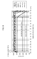
- Fig. 8 is a graph corresponding to Fig. 4 and illustrating illuminance distributions that are observed when light is emitted from the light source 512 provided at one end of the illuminating unit 510 of the image reading device 500 according to the second embodiment.
- the illuminance ratio at a height of the illuminated surface of 0 mm is substantially uniform over the entirety of the reading area, whereas the illuminance at the one end (the +Y-side end) of the reading area is reduced as the height of the illuminated surface increases.
- the aligning portion 507 is provided at the other end (the -Y-side end) of the reading area, i.e., on the side opposite the light source 512. Therefore, the illuminance ratio is substantially uniform over the entirety of the main original area at any height of the illuminated surface.
- the image reading device 500 has a small size, which contributes to a small installation area. Furthermore, even if the original 103 is lifted from the platen 104, the nonuniformity in illuminance is reduced.
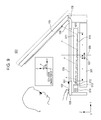
- FIG. 9 is a schematic diagram (a sectional view taken along the Y-Z plane) illustrating major elements of the image reading device 600 according to the third embodiment.
- the third embodiment differs from the first embodiment in that an aligning portion 607 of the image reading device 600 is provided on a side opposite the aligning portion 307 of the image reading device 100. That is, an illuminating unit 610 included in the image reading device 600 includes a light source 612 only at one long-side end (the -Y-side end) of a light-guiding member 611, and the aligning portion 607 is provided on the same side (-Y side) as the light source 612 in the Y direction.
- the illuminating unit 610 includes no light source, substrate, or heat sink at the other long-side end (the +Y-side end) of the light-guiding member 611.
- the length of the holding portion 108 in the Y direction can be made smaller than in the illuminating unit of the two-end source type, leading to the realization of a size reduction of the image reading device 600.
- the light emitted from the light source 612 and reflected by an optical surface 615 of the light-guiding member 611 has a deviation characteristic of traveling only toward the +Y side as in the first embodiment.
- the area having no microscopic prisms is provided at the +Y-side end of the bottom surface.
- a center axis 621 of the optical surface 615 in the Y direction is intentionally shifted toward the light source 612 (toward the -Y side) with respect to the optical axis 306 defined by the optical unit 303.
- the hinge portions 106 are provided on the side (+Y side) opposite the light source 612 in the Y direction as in the first embodiment. Therefore, in combination with the effect of the above deviation characteristic, the illuminating light is prevented from entering the eyes of the user. Furthermore, in the image forming apparatus 1000 including the image reading device 600 according to the third embodiment, the electronic components such as the light source 612 are intentionally provided on the user side (on the -Y side) that is opposite the controller 305, whereby the above-described advantageous effect is exerted.
- Fig. 10 is a graph corresponding to Fig. 4 and illustrating illuminance distributions that are observed when light is emitted from the light source 612 provided at one end of the illuminating unit 610 of the image reading device 600 according to the third embodiment.
- the illuminance ratio at a height of the illuminated surface of 0 mm is substantially uniform over the entirety of the reading area, whereas the illuminance ratio at one end (the -Y-side end) of the reading area is reduced as the height of the illuminated surface increases.
- the aligning portion 607 is provided at the -Y-side end of the reading area, i.e., the side having the light source 612. Hence, if the original 103 is lifted from the platen 104, the illuminance ratio at the -Y-side end in the main original area is reduced. Nevertheless, since the aligning portion 607 is provided on the user side (-Y side), the load applied to the user placing the original 103 on the platen 104 is smaller than in the first embodiment. Therefore, the image reading device 600 is easy to use even by a user who is short.
- the image reading device 600 has a small size, which contributes to a small installation area. Furthermore, the illuminating light from the illuminating unit 610 is prevented from entering the eyes of the user. Modifications
- the light source may be an electroluminescent light source (such as an organic light-emitting diode), a light bulb, or the like.
- the linear sensor may include a plurality of such line sensors that are arranged side by side in the short-side direction.
- the material of the platen is not limited to glass and may be resin or the like.
- the material of the light-guiding member is not limited to resin and may be glass or the like.
- the plurality of microscopic prisms provided to the light-guiding member may each have a mountain-like shape or a trapezoidal shape.
- the optical surfaces forming the microscopic prisms are not limited to flat surfaces and may be curved surfaces.
- the light-guiding member may be a plate-like member such as a reflector.
Landscapes
- Engineering & Computer Science (AREA)
- Multimedia (AREA)
- Signal Processing (AREA)
- Physics & Mathematics (AREA)
- Optics & Photonics (AREA)
- Facsimile Scanning Arrangements (AREA)
- Light Sources And Details Of Projection-Printing Devices (AREA)
Abstract
Description
- The present invention relates to an image reading device and is suitable for a digital copying machine, an image scanner, and the like.
- Illuminating units included in known image reading devices employ light-emitting diodes (hereinafter abbreviated to LEDs) that are highly durable and highly efficient in light utilization. An image reading device disclosed by
Japanese Patent Laid-Open No. 2012-160940 - The illuminating unit of the two-end source type disclosed by
Japanese Patent Laid-Open No. 2012-160940 - The present invention provides a compact image reading device and a compact image forming apparatus.
- The present invention in its first aspect provides an image reading device as specified in
claims 1 to 8. - The present invention in its second aspect provides an image forming apparatus as specified in
claims 9 and 10. - The present invention in its third aspect provides an image reading device as specified in claims 11 to 15.
- Further features of the present invention will become apparent from the following description of exemplary embodiments with reference to the attached drawings.
-
-
Fig. 1 is a schematic diagram illustrating major elements of an image forming apparatus according to a general embodiment of the present invention. -
Fig. 2 is a sectional view illustrating major elements of a carriage according to the general embodiment of the present invention. -
Fig. 3 is a sectional view illustrating major elements of an image reading device according to a first embodiment of the present invention. -
Fig. 4 is a graph illustrating illuminance distributions observed in the first embodiment of the present invention. -
Fig. 5 is a sectional view illustrating major elements of an image reading device according to a comparative embodiment. -
Fig. 6A is a graph illustrating illuminance distributions observed with one of light sources provided at two respective ends of the image reading device according to the comparative embodiment. -
Fig. 6B is a graph illustrating illuminance distributions observed with both of the light sources provided at the two respective ends of the image reading device according to the comparative embodiment. -
Fig. 7 is a sectional view illustrating major elements of an image reading device according to a second embodiment of the present invention. -
Fig. 8 is a graph illustrating illuminance distributions observed in the second embodiment of the present invention. -
Fig. 9 is a sectional view illustrating major elements of an image reading device according to a third embodiment of the present invention. -
Fig. 10 is a graph illustrating illuminance distributions observed in the third embodiment of the present invention. - Embodiments of the present invention will now be described with reference to the attached drawings. Like elements illustrated in the drawings are denoted by like reference numerals, whereby redundant description thereof is omitted.
-
Fig. 1 is a schematic diagram illustrating major elements of animage forming apparatus 1000 according to a general embodiment of the present invention that includes animage reading device 100 and animage forming device 200. A user can give instructions to theimage forming apparatus 1000 by using anoperation portion 102 while checking information displayed on adisplay portion 101. Theimage reading device 100 according to the general embodiment is capable of reading an A3-size original and has a reading area (an illuminated area) of about 300 mm x 420 mm. - The
image reading device 100 includes aplaten 104 on which an original 103 is to be placed, an originalpressing plate 105 configured to press the original 103 against theplaten 104, aholding portion 108 configured to hold theplaten 104, and acarriage 300 provided below theplaten 104. In the general embodiment, theplaten 104 is made of glass, the originalpressing plate 105 is attached to theholding portion 108 withhinge portions 106, and thecarriage 300 is capable of scanning the original 103 while moving in an X direction (a subscanning direction). -
Fig. 2 is a sectional view of thecarriage 300 taken along a Z-X plane. Thecarriage 300 includes ahousing 301, anilluminating unit 310 configured to illuminate the original 103, alinear sensor 304 configured to receive light from the original 103, anoptical unit 303 configured to guide the light from the original 103 to thelinear sensor 304, and a plurality ofmirrors 302 that reflect the light from the original 103 and are provided in an optical path between the original 103 and theoptical unit 303. In the general embodiment, theoptical unit 303 is a reduction imaging system, and thelinear sensor 304 is a line sensor (including pixels that are arranged one-dimensionally in a Y direction) extending in the Y direction (a direction perpendicular to the page surface). - An image of the original 103 that is formed on the
linear sensor 304 is transmitted as one-dimensional image information to acontroller 305. Thecontroller 305 receives a piece of one-dimensional image information every time thecarriage 300 reads the original 103, thereby acquiring two-dimensional image information including a plurality of pieces of one-dimensional image information. Furthermore, thecontroller 305 corrects pieces of information on the color, contrast, and so forth of the image, converts the corrected pieces of information into signals, and transmits the signals to theimage forming device 200. Theimage forming device 200 forms an image on a recording medium such as paper in an electrophotographic manner, an inkjet manner, or the like in accordance with the signals received from thecontroller 305. - The
illuminating unit 310 according to the general embodiment includes a light-guiding member extending in a long-side direction of thelinear sensor 304, and a light source provided only at one long-side end of the light-guiding member. Therefore, theimage reading device 100 can have a smaller size and requires a smaller area of installation than the illuminating unit of the two-end source type. Furthermore, theimage reading device 100 according to the general embodiment includes an aligning portion with reference to which the position of the original 103 in the long-side direction of the linear sensor 304 (the long-side direction of the light-guiding member) is determined. The aligning portion is provided on a side opposite the light source in the long-side direction of the light-guiding member. In such a configuration, even if the original 103 is lifted from theplaten 104, the nonuniformity in illuminance that may occur because of a reduction in the illuminance at two ends of the illuminated area is reduced (details will be described separately below). - The
image reading device 100 according to the general embodiment will further be described as more specific embodiments. - An
image reading device 100 according to a first embodiment of the present invention will now be described in detail.Fig. 3 is a schematic diagram (a sectional view taken along a Y-Z plane) illustrating major elements of theimage reading device 100 according to the first embodiment. Anilluminating unit 310 according to the first embodiment includes a light source (LED) 312 mounted on asubstrate 313, a light-guidingmember 311 having a plane of incidence on a side thereof facing thelight source 312, and aheat sink 314 provided on the back side of the substrate 313 (on a side opposite the side on which thelight source 312 is mounted) and that exhausts heat generated from thelight source 312. The long-side direction of the light-guidingmember 311 corresponds to the Y direction (a main scanning direction). - As illustrated in
Fig. 3 , theilluminating unit 310 employs a configuration in which thelight source 312 is provided only at one long-side end (a -Y-side end) of the light-guiding member 311 (such a configuration is hereinafter referred to as one-end source type). In the one-end source type, the other long-side end (a +Y-side end) of the light-guidingmember 311 is provided with no light source, substrate, or heat sink. Therefore, the length of theholding portion 108 in the Y direction can be made smaller than in the two-end source type. Thus, theimage reading device 100 can have a small size. - The light-guiding
member 311 has, at the bottom thereof, an optical surface (a secondary light-source surface) 315 in which a plurality of microscopic prisms (a group of secondary light sources) are aligned in the Y direction. Theoptical surface 315 behaves like a light source that emits light by itself. Such a behavior is based on total reflection. Accordingly, the light emitted from theoptical surface 315 is characterized in traveling with an angular distribution deviating in a direction away from the light source 312 (such a characteristic is hereinafter referred to as deviation characteristic). In the first embodiment, the light reflected by theoptical surface 315 has a deviation characteristic of traveling only toward a +Y side. The present inventor has focused on such a deviation characteristic observed in the one-end source type and has found that effects produced by providing the microscopic prisms are reduced near the +Y-side end of the light-guidingmember 311. - Hence, in the light-guiding
member 311 according to the first embodiment, a portion of the bottom surface thereof at the end on the side (the +Y side) opposite thelight source 312 has no microscopic prisms. Furthermore, in the long-side direction of the light-guiding member 311 (the Y direction), the distance between acenter axis 321 of theoptical surface 315 and thelight source 312 is shorter than the distance between anoptical axis 306 defined by theoptical unit 303 and thelight source 312. That is, thecenter axis 321 of theoptical surface 315 is intentionally shifted toward thelight source 312 with respect to theoptical axis 306 of theoptical unit 303. With such a configuration, the size of the light-guidingmember 311 is reduced. Moreover, the area of a mold that is to be processed for forming the light-guidingmember 311 having the microscopic prisms from resin is reduced. Therefore, the abrasion of a cutting tool is suppressed, and the light-guidingmember 311 is formed with high accuracy and at a low cost. - In a reduction imaging method employed in a reduction imaging system such as the
image reading device 100 according to the first embodiment, the depth of field is larger than that of a device of a contact-image-sensor type that employs a 1x-magnification optical system. Hence, according to the reduction imaging method, satisfactory contrast performance is obtained even if the original is lifted from the platen by up to dozens of millimeters. In a commonly known image reading device, it is desired to maintain high and uniform illuminance even if the original is lifted to a significant height (over dozens of millimeters). - On the platen 104 (at a height of an illuminated surface of 0 mm), the illuminating
unit 310 substantially uniformly illuminates the entirety of an area extending from the end on the side (the -Y side) nearer to thelight source 312 to the end on the side (the +Y side) opposite thelight source 312. As described above, however, the light reflected by theoptical surface 315 has a deviation characteristic of traveling only toward the +Y side. Hence, as the height of the illuminated surface increases, the distribution of the quantity of illuminating light deviates toward the side (+Y side) opposite thelight source 312. That is, because of the above deviation characteristic, the quantity of illuminating light on the side nearer to thelight source 312 in the Y direction is significantly reduced with the increase in the height of the illuminated surface. - Hence, the first embodiment employs a configuration in which an aligning
portion 307 with reference to which the position of the original 103 in the Y direction is determined is provided at a position corresponding to the end of the light-guidingmember 311 that is on the side (+Y side) opposite thelight source 312 in the Y direction. In such a configuration, the original 103 is positioned away from a side of theplaten 104 that is nearer to thelight source 312 in the Y direction. Therefore, in combination with the deviation characteristic observed in the one-end source type, the quantity of light is maintained to be substantially constant even if the height of the illuminated surface changes. That is, even if the original 103 is lifted from theplaten 104, the uniformity in the illuminance of the light applied to the original 103 is maintained. -
Fig. 4 is a graph illustrating illuminance distributions that are observed when light is emitted from thelight source 312 provided at one end of the light-guidingmember 311 of theimage reading device 100 according to the first embodiment. InFig. 4 , the horizontal axis represents the reading position in the Y direction (the main-scan reading position), and the vertical axis represents the illuminance ratio (the relative value of illuminance with the peak value being 100%) of the light received by thelinear sensor 304. The curves represent illuminance distributions observed with respective amounts of lifting of the surface of the original 103 (at respective heights of the illuminated surface) from theplaten 104. The original 103 is positioned within the reading area (an area to be illuminated by the illuminating unit 310) on theplaten 104. - Such a reduction imaging method has a problem in that the quantity of light received at an end of the
linear sensor 304 is reduced because of the field-angle characteristic (the cosine-fourth-power law) of theoptical unit 303 even if the original 103 is not lifted. To solve this problem, in the first embodiment, the microscopic prisms are provided appropriately in the light-guidingmember 311, whereby the illuminance ratio at a height of the illuminated surface of 0 mm is made substantially uniform over the entirety of the reading area as graphed inFig. 4 . - Referring to
Fig. 4 , however, as the height of the illuminated surface increases, the illuminance ratio at one end (the -Y-side end) of the reading area is reduced. At a height of the illuminated surface of 40 mm, the illuminance ratio at the -Y-side end of the reading area is reduced to about 20%. In general, the bound portion of a thick original, such as a dictionary, tends to reside at a large height. The lengths of many such originals in the Y direction are about 260 mm. - In a case where such an original is placed on the
platen 104 while being aligned with reference to the aligningportion 307 according to the first embodiment, a main original area represented inFig. 4 is to be read. In this case, as can be seen fromFig. 4 , the illuminance ratio is substantially uniform over the entirety of the main original area at any height of the illuminated surface. Thus, in the first embodiment, since the aligningportion 307 is provided on the other end (the +Y-side end) of the reading area, i.e., the side opposite thelight source 312, the influence of the reduction in the illuminance ratio at the -Y-side end is avoided. - In the first embodiment, the aligning
portion 307 is provided on the holdingportion 108. The aligningportion 307 may be provided at any other position, for example, a position on theplaten 104, as long as the position of the original 103 in the Y direction is determinable. In the first embodiment, the aligningportion 307 is provided such that a surface (an aligning surface) thereof with which the original 103 comes into contact extends in a direction (the X direction) perpendicular to the long-side direction of the light-guiding member 311 (the Y direction). That is, the aligningportion 307 has a continuous aligning surface whose long-side direction corresponds to the X direction. The term "perpendicular" used herein includes "substantially perpendicular". Hence, as long as the position of the original 103 in the Y direction is determinable, the aligning surface does not necessarily extend exactly in the X direction or is not necessarily continuous. - In the
image reading device 100 according to the first embodiment, as illustrated inFig. 3 , thehinge portions 106 with which the originalpressing plate 105 is openable and closable are provided on the side (the +Y side) opposite thelight source 312 in the Y direction. In such a configuration, the user inevitably stands on the side nearer to thelight source 312 so as to open or close the originalpressing plate 105. In this state, the illuminating light that has been reflected by theoptical surface 315 travels only toward the +Y side because of the above-described deviation characteristic of the one-end source type. Therefore, the illuminating light is prevented from entering the eyes of the user. If an original such as a dictionary is to be read, since such an original has a width smaller than that of an A3-size original, a large quantity of illuminating light leaks from the reading area. Hence, the above effect is exerted more advantageously. - Referring now to
Fig. 1 , thecontroller 305 included in theimage forming apparatus 1000 is provided on a side nearer to the hinge portions 106 (on the +Y side), i.e., a side opposite a user side (the -Y side). This is because of the following reasons. Thedisplay portion 101 and theoperation portion 102 are provided on the user side. Furthermore, spaces for supplying toner, ink, and pieces of paper and for other kinds of work need to be provided on the user side of theimage forming device 200. Such circumstances makes it difficult to provide thecontroller 305 on the user side. - Hence, as a matter of convenience in design, electronic components such as the
light source 312 included in the illuminatingunit 310 may be typically provided on the +Y side, as with thecontroller 305, so that the distance between each of those electronic components and thecontroller 305 that are connected to each other is reduced. In theimage forming apparatus 1000 including theimage reading device 100 according to the first embodiment, however, the electronic components such as thelight source 312 are intentionally provided on the user side (the -Y side) that is opposite thecontroller 305, whereby the above-described advantageous effect is exerted. - As illustrated in
Fig. 3 , if the aligningportion 307 has a color that is different from that of a member, such as the holdingportion 108, provided adjacent thereto, the user can visually identify the aligningportion 307 more easily. Such a configuration contributes to accurate positioning of the original 103. The aligningportion 307 may be colored over the entirety thereof or only partially (as patterns or characters). - When the length of the illuminated area (reading area) illuminated by the illuminating
unit 310 is 250 mm or larger in the long-side direction of the light-guiding member 311 (the Y direction), the above-mentioned problems (the nonuniformity in illuminance and the leakage of illuminating light) are particularly pronounced and the effects produced in the first embodiment of the present invention are exerted more advantageously. In the first embodiment, since the illuminated area is set to a size of about 300 mm x 420 mm so that an A3-size original is readable, the advantageous effects produced in the first embodiment of the present invention are satisfactorily exerted. - To summarize, the
image reading device 100 according to the first embodiment has a small size, which contributes to a small installation area. Furthermore, even if the original 103 is lifted from theplaten 104, the nonuniformity in illuminance is reduced. Furthermore, the illuminating light emitted from the illuminatingunit 310 is prevented from entering the eyes of the user and dazzling the user (giving discomfort to the user). Comparative Embodiment - A comparative embodiment with respect to the first embodiment of the present invention will now be described.
Fig. 5 is a schematic diagram (a sectional view taken along the Y-Z plane) illustrating major elements of animage reading device 400 according to the comparative embodiment. The comparative embodiment differs from the first embodiment in that theimage reading device 400 includes an illuminatingunit 410 of the two-end source type and that microscopic prisms are provided over the entirety of the bottom surface of a light-guidingmember 411. That is, the illuminatingunit 410 includes alight source 412, asubstrate 413, and aheat sink 414 that are provided at each of two long-side (Y-direction) ends of the light-guidingmember 411 and has a configuration in which the center axis of anoptical surface 415 coincides with theoptical axis 306 of theoptical unit 303. -
Fig. 6A is a graph corresponding toFig. 4 and illustrating illuminance distributions that are observed in theimage reading device 400 according to the comparative embodiment when light is emitted from only thelight source 412 provided at the +Y-side end of the light-guidingmember 411. Illuminance distributions that are observed when light is emitted from only thelight source 412 provided at the -Y-side end of the light-guidingmember 411 are obtained by horizontally inverting the illuminance distributions graphed inFig. 6A . InFig. 6A , as the height of the illuminated surface increases, the center of the illuminance distribution deviates in a direction away from the +Y-side end because of the deviation characteristic that is observed by allowing only thelight source 412 on the +Y side to emit light. The illuminance ratio sharply drops at a position near thelight source 412. At a height of the illuminated surface of 40 mm, the illuminance ratio at the +Y-side end of the reading area drops to about 25%. - Hence, in the comparative embodiment, both of the
light sources 412 provided at the two respective ends of the light-guidingmember 411 are allowed to emit light simultaneously, whereby illuminance distributions graphed inFig. 6B are obtained as a combination of the illuminance distributions graphed inFig. 6A and the illuminance distributions as horizontal inversions thereof. As can be seen fromFig. 6B , at a height of the illuminated surface of 0 mm, the illuminance ratio is substantially uniform over the entirety of the main reading area, as in the first embodiment. Compared with the illuminance distributions graphed inFig. 6A , the illuminance ratios at the two respective ends of the reading area observed when the original 103 is lifted are increased in the illuminance distributions graphed inFig. 6B . - In the comparative embodiment, however, the reduction in the illuminance ratio at the two ends of the reading area due to the increase in the height of the illuminated surface is not suppressed completely. For example, at a height of the illuminated surface of 40 mm, the illuminance ratio at the two ends of the reading area is reduced to about 50%. Hence, in the
image reading device 400 according to the comparative embodiment, even if an aligningportion 407 is provided at the end on the side (the +Y side) opposite thelight source 412 provided at the -Y-side end in the Y direction as in the first embodiment, the illuminance distribution in the main original area becomes nonuniform. Nevertheless, if the original 103 is placed away from the aligningportion 407, adverse influences due to the reduction in the illuminance ratio are reduced. In such a case, however, the original 103 is not positioned with reference to the aligningportion 407, which is impractical. - If the original 103 is read by using the illuminating
unit 410 according to the comparative embodiment that is of the two-end source type, the above-described nonuniformity in illuminance may adversely affect the resulting image in various ways. For example, if an original 103, such as a dictionary whose pages have a white base color, is read as a color or gray-scale image represented with gradation, the resulting image may have nonuniformity appearing as a change of the color from white to gray near an end of the bound portion of the original 103. For another example, if the above original 103 is read as a binary image represented by black and white with no gradation, a base portion (a portion having no printed images) of the original 103 near the end of the bound portion may be read as black. In such a case, characters and so forth printed on that portion may disappear. - In the illuminating
unit 410 according to the comparative embodiment illustrated inFig. 5 , rays emitted from the -Y-side end and the +Y-side end and reflected by theoptical surface 415 have deviation characteristics of traveling toward the +Y side and the -Y side, respectively. Hence, in theimage reading device 400 according to the comparative embodiment, even if thehinge portions 106 are provided on the side (+Y side) opposite thelight source 412 provided at the -Y-side end in the Y direction as in the first embodiment, rays traveling toward the -Y side are not prevented from entering the eyes of the user. - As described above, the illuminating
unit 410 according to the comparative embodiment is of the two-end source type. Therefore, unlike the illuminatingunit 310 according to the first embodiment, the area of theoptical surface 415 cannot be reduced, and the center axis of theoptical surface 415 in the Y direction cannot be shifted with respect to theoptical axis 306 of theoptical unit 303. Hence, in the comparative embodiment, the size reduction of the light-guidingmember 411 and the high-accuracy, low-cost processing of the mold for the light-guidingmember 411 are not realized. - An
image reading device 500 according to a second embodiment of the present invention will now be described in detail.Fig. 7 is a schematic diagram (a sectional view taken along the Y-Z plane) illustrating major elements of theimage reading device 500 according to the second embodiment. The second embodiment differs from the first embodiment in that alight source 512 and an aligningportion 507 of theimage reading device 500 are each provided on a side opposite a corresponding one of thelight source 312 and the aligningportion 307 of theimage reading device 100. That is, in theimage reading device 500, an illuminatingunit 510 includes thelight source 512 only at one long-side end (the +Y-side end) of a light-guidingmember 511 while the aligningportion 507 is provided on a side (-Y side) opposite thelight source 512 in the Y direction. - As illustrated in
Fig. 7 , the illuminatingunit 510 includes no light source, substrate, or heat sink at the other long-side end (the -Y-side end) of the light-guidingmember 511. Hence, the length of the holdingportion 108 in the Y direction can be made smaller than in the illuminating unit of the two-end source type, leading to the realization of a size reduction of theimage reading device 500. Particularly, in the second embodiment, the length of the holdingportion 108 can be shortened on the user side (-Y side). Therefore, even a user who is short can easily place the original 103 on theplaten 104. - In the second embodiment, the light emitted from the
light source 512 and reflected by anoptical surface 515 of the light-guidingmember 511 has a deviation characteristic of traveling only toward the -Y side, which is opposite to the characteristic observed in the first embodiment. Hence, in the light-guidingmember 511 according to the second embodiment, the area having no microscopic prisms is provided at the -Y-side end of the bottom surface. Furthermore, acenter axis 521 of theoptical surface 515 in the Y direction is intentionally shifted toward the side (+Y side) opposite thelight source 512 with respect to theoptical axis 306 defined by theoptical unit 303. With such a configuration, the size reduction of the light-guidingmember 511 and the high-accuracy, low-cost processing of the mold for the light-guidingmember 511 are realized as in the first embodiment. - In the second embodiment also, since the aligning
portion 507 is provided on the side (-Y side) opposite thelight source 512, even if the original 103 is lifted from theplaten 104, the uniformity in the illuminance of the light applied to the original 103 is maintained by utilizing the deviation characteristic as in the first embodiment. Such an advantageous effect will now be described more specifically with reference toFig. 8 . -
Fig. 8 is a graph corresponding toFig. 4 and illustrating illuminance distributions that are observed when light is emitted from thelight source 512 provided at one end of the illuminatingunit 510 of theimage reading device 500 according to the second embodiment. As graphed inFig. 8 , the illuminance ratio at a height of the illuminated surface of 0 mm is substantially uniform over the entirety of the reading area, whereas the illuminance at the one end (the +Y-side end) of the reading area is reduced as the height of the illuminated surface increases. Nevertheless, in the second embodiment, the aligningportion 507 is provided at the other end (the -Y-side end) of the reading area, i.e., on the side opposite thelight source 512. Therefore, the illuminance ratio is substantially uniform over the entirety of the main original area at any height of the illuminated surface. - To summarize, the
image reading device 500 according to the second embodiment has a small size, which contributes to a small installation area. Furthermore, even if the original 103 is lifted from theplaten 104, the nonuniformity in illuminance is reduced. - An
image reading device 600 according to a third embodiment of the present invention will now be described in detail.Fig. 9 is a schematic diagram (a sectional view taken along the Y-Z plane) illustrating major elements of theimage reading device 600 according to the third embodiment. The third embodiment differs from the first embodiment in that an aligningportion 607 of theimage reading device 600 is provided on a side opposite the aligningportion 307 of theimage reading device 100. That is, an illuminatingunit 610 included in theimage reading device 600 includes alight source 612 only at one long-side end (the -Y-side end) of a light-guidingmember 611, and the aligningportion 607 is provided on the same side (-Y side) as thelight source 612 in the Y direction. - As illustrated in
Fig. 9 , the illuminatingunit 610 includes no light source, substrate, or heat sink at the other long-side end (the +Y-side end) of the light-guidingmember 611. Hence, the length of the holdingportion 108 in the Y direction can be made smaller than in the illuminating unit of the two-end source type, leading to the realization of a size reduction of theimage reading device 600. - In the third embodiment, the light emitted from the
light source 612 and reflected by anoptical surface 615 of the light-guidingmember 611 has a deviation characteristic of traveling only toward the +Y side as in the first embodiment. Hence, in the light-guidingmember 611 according to the third embodiment, the area having no microscopic prisms is provided at the +Y-side end of the bottom surface. Furthermore, acenter axis 621 of theoptical surface 615 in the Y direction is intentionally shifted toward the light source 612 (toward the -Y side) with respect to theoptical axis 306 defined by theoptical unit 303. With such a configuration, the size reduction of the light-guidingmember 611 and the high-accuracy, low-cost processing of the mold for the light-guidingmember 611 are realized as in the first embodiment. - In the third embodiment also, the
hinge portions 106 are provided on the side (+Y side) opposite thelight source 612 in the Y direction as in the first embodiment. Therefore, in combination with the effect of the above deviation characteristic, the illuminating light is prevented from entering the eyes of the user. Furthermore, in theimage forming apparatus 1000 including theimage reading device 600 according to the third embodiment, the electronic components such as thelight source 612 are intentionally provided on the user side (on the -Y side) that is opposite thecontroller 305, whereby the above-described advantageous effect is exerted. -
Fig. 10 is a graph corresponding toFig. 4 and illustrating illuminance distributions that are observed when light is emitted from thelight source 612 provided at one end of the illuminatingunit 610 of theimage reading device 600 according to the third embodiment. As graphed inFig. 10 , the illuminance ratio at a height of the illuminated surface of 0 mm is substantially uniform over the entirety of the reading area, whereas the illuminance ratio at one end (the -Y-side end) of the reading area is reduced as the height of the illuminated surface increases. - In the third embodiment, the aligning
portion 607 is provided at the -Y-side end of the reading area, i.e., the side having thelight source 612. Hence, if the original 103 is lifted from theplaten 104, the illuminance ratio at the -Y-side end in the main original area is reduced. Nevertheless, since the aligningportion 607 is provided on the user side (-Y side), the load applied to the user placing the original 103 on theplaten 104 is smaller than in the first embodiment. Therefore, theimage reading device 600 is easy to use even by a user who is short. - To summarize, the
image reading device 600 according to the third embodiment has a small size, which contributes to a small installation area. Furthermore, the illuminating light from the illuminatingunit 610 is prevented from entering the eyes of the user. Modifications - While some specific embodiments of the present invention have been described above, the present invention is not limited thereto. Various changes and modifications can be made to the above embodiments within the scope of the present invention.
- For example, while each of the above embodiments employs an LED as the light source, the light source may be an electroluminescent light source (such as an organic light-emitting diode), a light bulb, or the like. Furthermore, while each of the above embodiments employs a line sensor including pixels that are arranged one-dimensionally as the linear sensor, the linear sensor may include a plurality of such line sensors that are arranged side by side in the short-side direction.
- The material of the platen is not limited to glass and may be resin or the like. The material of the light-guiding member is not limited to resin and may be glass or the like. The plurality of microscopic prisms provided to the light-guiding member may each have a mountain-like shape or a trapezoidal shape. The optical surfaces forming the microscopic prisms are not limited to flat surfaces and may be curved surfaces. Moreover, the light-guiding member may be a plate-like member such as a reflector.
- While each of the above embodiments is based on an assumption that a thick original such as a dictionary (an original having a bound portion) is to be read, the present invention is not limited to such a case. The advantageous effects of the present invention are also exerted in a case where an original having a wavy surface, a three-dimensional original, or the like is to be read.
- While the present invention has been described with reference to exemplary embodiments, it is to be understood that the invention is not limited to the disclosed exemplary embodiments. The scope of the following claims is to be accorded the broadest interpretation so as to encompass all such modifications and equivalent structures and functions.
Claims (15)
- An image reading device (100, 500) comprising:a platen (104) on which an original (103) is to be placed;an illuminating unit (310, 510) configured to illuminate the original;a linear sensor (304) configured to receive light from the original;an optical unit (303) configured to guide the light from the original to the linear sensor; andan aligning portion (307, 507) configured to determine a position of the original in a long-side direction of the linear sensor,wherein the illuminating unit includes
a light-guiding member (311, 511) extending in the long-side direction of the linear sensor; and
a light source (312, 512) provided only at one long-side end of the light-guiding member, andwherein the aligning portion is provided on a side opposite the light source in the long-side direction of the light-guiding member. - The image reading device according to Claim 1, wherein the light-guiding member includes an optical surface (315, 515) provided with a plurality of prisms that are arranged in the long-side direction of the light-guiding member.
- The image reading device according to Claim 2, wherein, in the long-side direction of the light-guiding member, a distance between a center axis (321, 521) of the optical surface and the light source is shorter than a distance between an optical axis (306) defined by the optical unit and the light source.
- The image reading device according to any one of Claims 1 - 3, wherein a surface of the aligning portion with which the original comes into contact extends in a direction perpendicular to the long-side direction of the light-guiding member.
- The image reading device according to any one of Claims 1 - 4, wherein, in the long-side direction of the light-guiding member, a length of an illuminated area illuminated by the illuminating unit is at least 250 mm.
- The image reading device according to any one of Claims 1 - 5, wherein the aligning portion has a color different from a color of a member provided adjacent to the aligning portion.
- The image reading device according to any one of Claims 1 - 6, wherein the optical unit is a reduction imaging system.
- The image reading device according to any one of Claims 1 - 7, further comprising:an original pressing plate (105) configured to press the original against the platen; anda hinge portion (106) with which the original pressing plate is openable and closeable,wherein the hinge portion is provided on a side opposite the light source in the long-side direction of the light-guiding member.
- An image forming apparatus (1000) comprising:an image reading device (100, 500) including
a platen (104) on which an original (103) is to be placed,
an illuminating unit (310, 510) configured to illuminate the original,
a linear sensor (304) configured to receive light from the original,
an optical unit (303) configured to guide the light from the original to the linear sensor, and
an aligning portion (307, 507) configured to determine a position of the original in a long-side direction of the linear sensor; andan image forming device (200) configured to form an image of the original that has been read by the linear sensor on a recording medium,wherein the illuminating unit includes
a light-guiding member (311, 511) extending in the long-side direction of the linear sensor; and
a light source (312, 512) provided only at one long-side end of the light-guiding member, andwherein the aligning portion is provided on a side opposite the light source in the long-side direction of the light-guiding member. - The image forming apparatus according to Claim 9, further comprising:a controller (305) configured to convert information acquired from the image reading device into a signal and transmit the information to the image forming device,wherein the controller is provided on the side opposite the light source in the long-side direction of the light-guiding member.
- An image reading device (600) comprising:a platen (104) on which an original (103) is to be placed;an illuminating unit (610) configured to illuminate the original;a linear sensor (304) configured to receive light from the original;an optical unit (303) configured to guide the light from the original to the linear sensor; andan original pressing plate (105) configured to press the original against the platen; anda hinge portion (106) with which the original pressing plate is openable and closeable,wherein the illuminating unit includes
a light-guiding member (611) extending in the long-side direction of the linear sensor; and
a light source (612) provided only at one long-side end of the light-guiding member, andwherein the hinge portion is provided on a side opposite the light source in the long-side direction of the light-guiding member. - The image reading device according to Claim 11, wherein the light-guiding member includes an optical surface (615) provided with a plurality of prisms that are arranged in the long-side direction of the light-guiding member.
- The image reading device according to Claim 12, wherein, in the long-side direction of the light-guiding member, a distance between a center axis (621) of the optical surface and the light source is shorter than a distance between an optical axis (306) defined by the optical unit and the light source.
- The image reading device according to any one of Claims 11 - 13, wherein, in the long-side direction of the light-guiding member, a length of an illuminated area illuminated by the illuminating unit is at least 250 mm.
- The image reading device according to any one of Claims 11 - 14, wherein the optical unit is a reduction imaging system.
Applications Claiming Priority (2)
| Application Number | Priority Date | Filing Date | Title |
|---|---|---|---|
| JP2013123216A JP6245854B2 (en) | 2013-06-11 | 2013-06-11 | Image reading apparatus and image forming apparatus having the same |
| JP2013123217A JP6245855B2 (en) | 2013-06-11 | 2013-06-11 | Image reading apparatus and image forming apparatus having the same |
Publications (1)
| Publication Number | Publication Date |
|---|---|
| EP2814232A1 true EP2814232A1 (en) | 2014-12-17 |
Family
ID=50942094
Family Applications (1)
| Application Number | Title | Priority Date | Filing Date |
|---|---|---|---|
| EP14171902.1A Withdrawn EP2814232A1 (en) | 2013-06-11 | 2014-06-11 | Image reading device and image forming apparatus including the same |
Country Status (4)
| Country | Link |
|---|---|
| US (1) | US9338322B2 (en) |
| EP (1) | EP2814232A1 (en) |
| KR (1) | KR101678272B1 (en) |
| CN (1) | CN104243755B (en) |
Citations (7)
| Publication number | Priority date | Publication date | Assignee | Title |
|---|---|---|---|---|
| DE3833371A1 (en) * | 1988-09-29 | 1990-04-05 | Siemens Ag | Folding lid for pressing an original (master) against a support surface (support plane) |
| CN1831423A (en) * | 2005-03-10 | 2006-09-13 | 佳能组件股份有限公司 | Linear lighting device and image access device using thereof |
| US20100277776A1 (en) * | 2009-04-30 | 2010-11-04 | Brother Kogyo Kabushiki Kaisha | Image Scanning Device |
| US20110267659A1 (en) * | 2010-04-28 | 2011-11-03 | Panasonic Corporation | Light guide body, and lighting apparatus and document scanning apparatus having the same |
| US20110286699A1 (en) * | 2010-05-24 | 2011-11-24 | Panasonic Corporation | Light guide body and lighting apparatus having the same |
| US20120147402A1 (en) * | 2010-12-13 | 2012-06-14 | Siow Kiat Tan | User identification for scanning apparatus |
| JP2012160940A (en) | 2011-02-01 | 2012-08-23 | Fuji Xerox Co Ltd | Correction device, image reading device, image forming device, and program |
Family Cites Families (15)
| Publication number | Priority date | Publication date | Assignee | Title |
|---|---|---|---|---|
| JPH09219768A (en) * | 1996-02-09 | 1997-08-19 | Canon Inc | Image sensor |
| US6333779B1 (en) * | 1998-12-24 | 2001-12-25 | Canon Kabushiki Kaisha | Illumination apparatus using light guide |
| TW503646B (en) * | 2000-03-16 | 2002-09-21 | Nippon Sheet Glass Co Ltd | Line illuminating device |
| JP2006270618A (en) * | 2005-03-24 | 2006-10-05 | Funai Electric Co Ltd | Original reading device |
| JP2008078855A (en) | 2006-09-20 | 2008-04-03 | Seiko Epson Corp | Light guide, illumination device, reading device, and image processing device |
| JP2010124118A (en) | 2008-11-18 | 2010-06-03 | Sharp Corp | Image reader and image forming apparatus |
| US8482824B2 (en) * | 2009-03-30 | 2013-07-09 | Brother Kogyo Kabushiki Kaisha | Image reading apparatus |
| CN201561291U (en) * | 2009-09-15 | 2010-08-25 | 一品光学工业股份有限公司 | Linear light source with prismatic ribbed reflective surface light guide |
| JP5132648B2 (en) | 2009-09-25 | 2013-01-30 | 三菱電機株式会社 | Illumination device and image reading device |
| CZ2010423A3 (en) * | 2010-05-28 | 2010-08-18 | Perner@Petr | Method and apparatus for continuous detection of thickness and/or homogeneity of a linear configuration, especially textile fiber |
| JP2012015987A (en) * | 2010-06-02 | 2012-01-19 | Rohm Co Ltd | Linear light source device and image reading apparatus |
| JP2012199764A (en) * | 2011-03-22 | 2012-10-18 | Konica Minolta Business Technologies Inc | Image reader |
| JP5578328B2 (en) * | 2011-05-31 | 2014-08-27 | コニカミノルタ株式会社 | Image reading device |
| MY164383A (en) * | 2011-06-20 | 2017-12-15 | Canon Finetech Nisca Inc | Image scanning unit |
| JP5514845B2 (en) * | 2012-01-31 | 2014-06-04 | 京セラドキュメントソリューションズ株式会社 | Light guide, image reading apparatus, and image forming apparatus |
-
2014
- 2014-06-09 US US14/299,532 patent/US9338322B2/en active Active
- 2014-06-10 KR KR1020140069977A patent/KR101678272B1/en active Active
- 2014-06-11 EP EP14171902.1A patent/EP2814232A1/en not_active Withdrawn
- 2014-06-11 CN CN201410257926.9A patent/CN104243755B/en active Active
Patent Citations (7)
| Publication number | Priority date | Publication date | Assignee | Title |
|---|---|---|---|---|
| DE3833371A1 (en) * | 1988-09-29 | 1990-04-05 | Siemens Ag | Folding lid for pressing an original (master) against a support surface (support plane) |
| CN1831423A (en) * | 2005-03-10 | 2006-09-13 | 佳能组件股份有限公司 | Linear lighting device and image access device using thereof |
| US20100277776A1 (en) * | 2009-04-30 | 2010-11-04 | Brother Kogyo Kabushiki Kaisha | Image Scanning Device |
| US20110267659A1 (en) * | 2010-04-28 | 2011-11-03 | Panasonic Corporation | Light guide body, and lighting apparatus and document scanning apparatus having the same |
| US20110286699A1 (en) * | 2010-05-24 | 2011-11-24 | Panasonic Corporation | Light guide body and lighting apparatus having the same |
| US20120147402A1 (en) * | 2010-12-13 | 2012-06-14 | Siow Kiat Tan | User identification for scanning apparatus |
| JP2012160940A (en) | 2011-02-01 | 2012-08-23 | Fuji Xerox Co Ltd | Correction device, image reading device, image forming device, and program |
Also Published As
| Publication number | Publication date |
|---|---|
| KR101678272B1 (en) | 2016-11-21 |
| US9338322B2 (en) | 2016-05-10 |
| US20140362423A1 (en) | 2014-12-11 |
| KR20140144660A (en) | 2014-12-19 |
| CN104243755A (en) | 2014-12-24 |
| CN104243755B (en) | 2018-01-30 |
Similar Documents
| Publication | Publication Date | Title |
|---|---|---|
| US8755092B2 (en) | Image reading apparatus illuminating a document with point light source and image forming apparatus | |
| US8279499B2 (en) | Single LED dual light guide | |
| US7672024B2 (en) | Contact image sensor module | |
| JP2009080173A (en) | Light guiding optical system, document illumination device using the same, and image reading device using the same | |
| US7535602B2 (en) | Image reading apparatus | |
| US7391543B2 (en) | Image reading apparatus | |
| US8169673B2 (en) | Illuminating device and image reading apparatus | |
| US20070247857A1 (en) | Document illuminator with stepped optical element | |
| US8253991B2 (en) | Duplex scanning apparatus | |
| JP6435790B2 (en) | Light irradiation apparatus, image reading apparatus, and image forming apparatus | |
| US9338322B2 (en) | Image reading device and image forming apparatus including an illuminating unit and an aligning portion for positioning an original | |
| EP1950945B1 (en) | Optical element for a document illuminator | |
| US9019575B2 (en) | Image reading apparatus and multifunction printing apparatus | |
| JP6245854B2 (en) | Image reading apparatus and image forming apparatus having the same | |
| JP4798275B2 (en) | Image reading device | |
| JP6245855B2 (en) | Image reading apparatus and image forming apparatus having the same | |
| US10009500B2 (en) | Light-guide member, illumination device, and image reading apparatus using a line-sequental method to illuminate a document for reading | |
| US7760434B2 (en) | Document illuminator with surface lens | |
| JP4396593B2 (en) | Image reading device | |
| JP6520402B2 (en) | Light irradiation apparatus, image reading apparatus and image forming apparatus | |
| JP2025099261A (en) | Lighting device and image reading device using the same | |
| JP2007184832A (en) | Illumination device for image reading apparatus, image reading apparatus | |
| JP2005130215A (en) | Image reading system and image reading method | |
| JP2001094737A (en) | Image reading device | |
| JP2004233513A (en) | Document illumination device |
Legal Events
| Date | Code | Title | Description |
|---|---|---|---|
| 17P | Request for examination filed |
Effective date: 20140611 |
|
| AK | Designated contracting states |
Kind code of ref document: A1 Designated state(s): AL AT BE BG CH CY CZ DE DK EE ES FI FR GB GR HR HU IE IS IT LI LT LU LV MC MK MT NL NO PL PT RO RS SE SI SK SM TR |
|
| AX | Request for extension of the european patent |
Extension state: BA ME |
|
| PUAI | Public reference made under article 153(3) epc to a published international application that has entered the european phase |
Free format text: ORIGINAL CODE: 0009012 |
|
| R17P | Request for examination filed (corrected) |
Effective date: 20150617 |
|
| RBV | Designated contracting states (corrected) |
Designated state(s): AL AT BE BG CH CY CZ DE DK EE ES FI FR GB GR HR HU IE IS IT LI LT LU LV MC MK MT NL NO PL PT RO RS SE SI SK SM TR |
|
| 17Q | First examination report despatched |
Effective date: 20190313 |
|
| STAA | Information on the status of an ep patent application or granted ep patent |
Free format text: STATUS: THE APPLICATION HAS BEEN WITHDRAWN |
|
| 18W | Application withdrawn |
Effective date: 20200514 |