EP2814185A1 - Method and apparatus for routing power line communication - Google Patents
Method and apparatus for routing power line communication Download PDFInfo
- Publication number
- EP2814185A1 EP2814185A1 EP20130198713 EP13198713A EP2814185A1 EP 2814185 A1 EP2814185 A1 EP 2814185A1 EP 20130198713 EP20130198713 EP 20130198713 EP 13198713 A EP13198713 A EP 13198713A EP 2814185 A1 EP2814185 A1 EP 2814185A1
- Authority
- EP
- European Patent Office
- Prior art keywords
- data collection
- micro inverter
- collection apparatus
- power line
- inverter
- Prior art date
- Legal status (The legal status is an assumption and is not a legal conclusion. Google has not performed a legal analysis and makes no representation as to the accuracy of the status listed.)
- Withdrawn
Links
Images





Classifications
-
- H—ELECTRICITY
- H04—ELECTRIC COMMUNICATION TECHNIQUE
- H04B—TRANSMISSION
- H04B3/00—Line transmission systems
- H04B3/54—Systems for transmission via power distribution lines
-
- H—ELECTRICITY
- H04—ELECTRIC COMMUNICATION TECHNIQUE
- H04B—TRANSMISSION
- H04B3/00—Line transmission systems
- H04B3/54—Systems for transmission via power distribution lines
- H04B3/548—Systems for transmission via power distribution lines the power on the line being DC
Definitions
- the present disclosure relates generally to a power line communication system, and more particularly to a power line communication routing system and a method of operating the same.
- the solar power system outputs the electricity generated from the solar panels through the power line.
- additional data transmission lines connected to the solar panels are used to transmit the data of the solar panels, such as the total power generating capacity or power generating efficiency of the solar panels.
- the above-mentioned data transmission lines would inevitably expose outside the building.
- the heat-resistant and water-proof materials are appropriate for the data transmission lines in order to provide better transmission quality through the data transmission lines, however, that increases the costs of the solar power system.
- PLC power line communication
- the same power line is usually connected to different large electrical apparatuses, such as the refrigerator, air conditioner, television, washing machine, computer, and so on.
- the amount of the electrical apparatuses connected to the power line is too much, or the unstable voltage caused by the old electrical apparatuses, it is easy to cause the harmonic pollution in the power line so that the solar panels cannot correctly communicate with external apparatuses and transmit data to each other.
- the transmitted data are distorted because of the harmonic pollution even if the solar panels can correctly transmit data through the power line.
- An object of the present disclosure is to provide a power line communication routing system and a method of operating the same that can overcome problems of incorrect commands and data transmission due to the too far distance or too much interference when a power line is provided to simultaneously transmit electricity, commands, and data.
- a power line communication (PLC) routing system includes a plurality of micro inverters and a data collection apparatus.
- the micro inverters are connected to the data collection apparatus through the power line to transmit electricity, commands, and data.
- the micro inverters register to the data collection apparatus.
- the data collection apparatus submits a connection request to the micro inverters and cannot acquire the corresponding responses
- the data collection apparatus commands the micro inverter which has received the response to submit the request instead of the micro inverter which does not reply the response within a timeout period.
- the micro inverter transmits the response to the data collection apparatus after receiving the replied data.
- the data collection apparatus cannot communicate with the micro inverters through the power line when too far distance between the micro inverter and the data collection apparatus or too much interference, such as the harmonic pollution generated due to excessive electrical apparatuses.
- the present disclosure has following features and advantages.
- the micro inverters connected to the power line can communicate to each other so that another micro inverter can be used to submit the request once the data collection apparatus cannot communicate with one of the micro inverters. Accordingly, the data collection apparatus can continuously submit the request to the micro inverter and normally receives the data replied from the micro inverter when the data collection apparatus cannot directly communicate with the micro inverter.
- the PLC routing system and the method are provided to overcome problems of incorrect commands and data transmission due to the too far distance or too much interference when a power line is provided to simultaneously transmit electricity, commands, and data.
- Fig. 1 is an architecture block diagram of a power line communication (PLC) routing system according to a first embodiment of the present disclosure.
- the PLC routing system mainly includes a plurality of micro inverters 1, a power line 4, and a data collection apparatus 6.
- the micro inverters 1 are connected to the data collection apparatus 6 through the power line 4 so as to transmit electricity, commands, and data.
- the power line 4 is a grid or an AC bus.
- the embodiment is only exemplified but is not intended to limit the scope of the disclosure.
- the PLC routing system is constructed in a building, such as a house.
- Each of the micro inverters 1 has a solar panel 2 and a DC-to-AC converter 3 electrically connected to the solar panel 2.
- the solar panel 2 is usually installed on the building roof to receive external light source and generate a DC power.
- the DC-to-AC converter 3 receives the DC power generated from the solar panel 2 and converts the DC power into an AC power, and the AC power is outputted through the power line 4.
- all of the micro inverters 1 are connected to the power line 4, and the power line 4 is connected to a power company 5 so that the redundant AC power outputted from the micro inverters 1 can be fed back and sold to the power company 5 through the power line 4.
- the data collection apparatus 6 submits a connection request to the micro inverts 1 to confirm operation conditions of the micro inverters 1 through the power line 4. In addition, the data collection apparatus 6 also submits a data request to the micro inverters 1 so that the micro inverters 1 can reply the corresponding data, such as the total power generating capacity or power generating efficiency of the solar panel 2 to the data collection apparatus 6.
- the micro inverters 1 are connected to the power line 4 in the building, that is, the micro inverters 1 are connected to the same power line 4 which is also connected to one or more electrical apparatuses 7, such as the refrigerator, air conditioner, television, computer, and so on.
- the data collection apparatus 6 cannot correctly communicate with the micro inverters 1 when the too far distance between the data collection apparatus 6 and the micro inverters 1 or the too much interference in the power line 4, such as the harmonic pollution generated due to excessive electrical apparatuses 7.
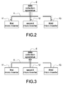
- Fig. 2 and Fig. 3 are schematic views of a first inquiry action and a second inquiry action according to the first embodiment of the present disclosure, respectively.
- the number of the micro inverters 1 is three, namely, a first micro inverter 11, a second micro inverter 12, and a third micro inverter 13, but not limited.
- the first micro inverter 11 has a first solar panel
- the second micro inverter 12 has a second solar panel
- the third micro inverter 13 has a third solar panel.
- first solar panel, the second solar panel, and the third solar panel are connected to the power line 4 through a first DC-to-AC converter, a second DC-to-AC converter, and a third DC-to-AC converter, respectively.
- first DC-to-AC converter a DC-to-AC converter
- second DC-to-AC converter a DC-to-AC converter
- third DC-to-AC converter respectively.
- the data collection apparatus 6 submits a request to the first, second, and third micro inverters 11, 12, 13 when data collection apparatus 6 wants to confirm operation conditions or collect relevant data of the first, second, and third micro inverters 11, 12, 13.
- the data collection apparatus 6 cannot correctly communicate with the third micro inverter 13 because of the too far distance between the data collection apparatus 6 and the third micro inverters 13 or the too much interference in the power line 4.
- the third micro inverter 13 still cannot correctly receive the request submitted from the data collection apparatus 6 because of above-mentioned problems.
- the third micro inverter 13 would miss the request submitted from the data collection apparatus 6 so that there will be no response transmitted from the third micro inverter 13 to the data collection apparatus 6.
- the data collection apparatus 6 can correctly receive the responses transmitted from the first micro inverter 11 and the second micro inverter 12, but the third micro inverter 13 does not reply the response within a timeout period.
- Fig. 4 is a flowchart of the inquiry action according to the first embodiment of the present disclosure.
- the data collection apparatus 6 can sequentially or randomly submits the connection request to the first, second, and third micro inverters 11, 12, 13 when data collection apparatus 6 wants to confirm operation conditions or collect relevant data of the first, second, and third micro inverters 11, 12, 13.
- the data collection apparatus 6 submits a connection request to the first micro inverter 11 through the power line 4 (S10).
- the first micro inverter 11 correctly receives the connection request (S11)
- the first micro inverter 11 transmits a connection response to the data collection apparatus 6 through the power line 4 (S12)
- the data collection apparatus 6 receives the connection response transmitted from the first micro inverter 11 through the power line 4 (S13).
- the data collection apparatus 6 submits a connection request to the second micro inverter 12 through the power line 4 (S14).
- the second micro inverter 12 correctly receives the connection request (S15)
- the second micro inverter 12 transmits a connection response to the data collection apparatus 6 through the power line 4 (S16), and then the data collection apparatus 6 receives the connection response transmitted from the second micro inverter 12 through the power line 4 (S17).
- the data collection apparatus 6 submits a connection request to the third micro inverter 13 through the power line 4 (S18).
- the data collection apparatus 6 cannot receive the response transmitted from the third micro inverter 13 because of the above-mentioned problems of incorrect commands and data transmission due to the too far distance or too much interference (S19).
- the data collection apparatus 6 records the response timeout of the third micro inverter 13 (S20).
- the data collection apparatus 6 regards the third micro inverter 13 as the first-type micro inverter when the response time of the third micro inverter exceeds a determined time.
- the first-type micro inverters are the micro inverters that cannot normally communicate with the data collection apparatus 6 due to the above-mentioned problems, the first-type micro inverters are probably faulted or in normal operation.
- Fig. 5 is a schematic view of a third inquiry action according to the first embodiment of the present disclosure.
- the data collection apparatus 6 regards the micro inverter that can normally and correctly communicate with the data collection apparatus 6 and reply the connection request as a second-type micro inverter.
- the data collection apparatus 6 commands the second-type micro inverter to submit the connection request instead of the first-type micro inverter.
- the data collection apparatus 6 regards the second micro inverter 12 as the second-type micro inverter.
- the data collection apparatus 6 commands the second micro inverter 12 to submit the connection request instead of the third micro inverter 13, receives the response of the third micro inverter 13, and transmits the response to the data collection apparatus 6.
- a distance between any two micro inverters is less than a distance between the data collection apparatus 6 and the first-type micro inverter. That is, a distance between the second-type micro inverter and the first-type micro inverter is less than a distance between the data collection apparatus 6 and the first-type micro inverter.
- the data collection apparatus 6 can give priority to select the micro inverter that is near the first-type micro inverter within a predetermined distance and can normally communicate with the data collection apparatus 6 as the second-type micro inverter.
- the second-type micro inverter is adjacent to the first-type micro inverter, but not limited.
- the data collection apparatus 6 can judge the distance between the first-type micro inverter and the second-type micro inverter or judge whether the second-type micro inverter is adjacent to the first-type micro inverter according to the media access control address (MAC Address), the serial number (SN), the personal identification number (PIN), the internet protocol address (IP Address), or so on.
- MAC Address media access control address
- SN serial number
- PIN personal identification number
- IP Address internet protocol address
- the second-type micro inverter plays a role of a relay apparatus between the data collection apparatus 6 and the first-type micro inverter so as to reduce the distance between the first-type micro inverter and data collection apparatus 6, thus increasing probability of correctly receiving the connection request of the first-type micro inverter.
- the data collection apparatus 6 when the data collection apparatus 6 submits the data requires to the micro inverters 1, the first-type micro inverter cannot correctly receive the data request submitted from the data collection apparatus 6. Therefore, the data collection apparatus 6 is connected to the second-type micro inverter which is adjacent or closer to the first-type micro inverter, and the data collection apparatus 6 commands the second-type micro inverter to submit the data request instead of the first-type micro inverter, also transmits the data replied from the first-type micro inverter to the data collection apparatus 6. Simultaneously, the second-type micro inverter can directly reply the corresponding data to the data collection apparatus 6 because the second-type micro inverter can correctly receive the data request submitted from the data collection apparatus 6.
- Fig. 6 is a block diagram of a DC-to-AC converter according to a first embodiment of the present disclosure.
- Each of the micro inverters 1 includes the solar panel 2 and the DC-to-AC converter 3.
- the DC-to-AC converter 3 has a DC-to-DC step-up module 31, a conversion module 32, a microprocessor 33, and a memory 34.
- the conversion module 32 is connected to the solar panel 2 and the power line 4.
- the solar panel 2 generates the DC power to the DC-to-AC converter 3.
- the DC-to-AC converter 3 receives the DC power generated from the solar panel 2 via the conversion module 32 and converts the DC power into the AC power, and the AC power is outputted through the power line 4.
- the AC power can supply power to the electrical apparatuses 7 connected to the power line 4, and also the redundant AC power can be fed back and sold to the power company 5.
- the DC-to-DC step-up module 31 electrically connected between the solar panel 2 and the conversion module 32.
- the DC-to-DC step-up module 31 receives the DC power generated from the solar panel 2 and boosts the DC power, and the boosted DC power is outputted to the conversion module 32 to be converted into the AC power by the conversion module 32.
- the DC-to-DC step-up module 31 is not necessary to be used depending on the actual demands.
- the microprocessor 33 is electrically connected to the conversion module 32 and the solar panel 2.
- the microprocessor 33 receives the request transmitted from the power line 4 and via the conversion module 32.
- the request is submitted from the data collection apparatus 6 or the second-type micro inverter through the power lien 4.
- the microprocessor 33 executes the corresponding action according to the request, such as the inquiry of the total power generating capacity or the power generating efficiency of the solar panel 2.
- the inquired data are replied to the data collection apparatus 6 or the second-type micro inverter.
- the memory 34 is electrically connected to the microprocessor 33 and has a register table T1 therein.
- Each of the micro inverters 1 has to register to the data collection apparatus 6 when the micro inverter is initially installed in the building so that the data collection apparatus 6 realizes the total number of the micro inverters 1 installed in the building.
- the second-type micro inverter can inquire the register table T1 to communicate with the data collection apparatus 6 according to the information of the first-type micro inverter when the second-type micro inverter receives the command transmitted from the data collection apparatus 6.
- Fig. 7 is a block diagram of a data collection apparatus according to a first embodiment of the present disclosure.
- the data collection apparatus 6 mainly includes a signal transmission unit 61, a microcontroller unit 62, a transmission unit 63, and a memory 64.
- the signal transmission unit 61 is provided to connect to the power line 4 so that the data collection apparatus 6 submits the request to the micro inverters 1 and receives the response transmitted from the micro inverters 1 through the power line 4.
- the microcontroller unit 62 is electrically connected to the signal transmission unit 61 to control the data collection apparatus producing and submitting the request, and also process the data received by the signal transmission unit 61.
- the microcontroller unit 62 can produce and submit the request to provide the total power generating capacity or the power generating efficiency according to setting values or the operation of the administrator.
- the transmission unit 63 is electrically connected to the microcontroller unit 62, and the data collection apparatus 6 is externally connected to a terminal apparatus 8 through the transmission unit 63.
- the transmission unit 63 is wirelessly connected to the terminal apparatus 8.
- the terminal apparatus 8 can be a wireless access point (AP) so that the data collection apparatus 6 can be connected to the terminal apparatus 8 through the transmission unit 63, and connected to a network through the terminal apparatus 8. Accordingly, the administrator can operate the data collection apparatus 6 through the network so as to register the micro inverters 1 to the data collection apparatus 6, enable the data collection apparatus 6 to submit the request, and access the collected data by the data collection apparatus 6.
- AP wireless access point
- the memory 64 is electrically connected to the microcontroller unit 62, and the memory 64 is provided to store the inquired data replied from the micro inverters 1.
- the memory 64 has an embedded web 641.
- the embedded web 641 is provided to receive the login information of the administrator when the administrator uses the computer to connect to the data collection apparatus 6 through the network so that the administrator can operate the embedded web 641 to register the micro inverters 1.
- the data collection apparatus 6 provides the register table T1 according to the registered results and the register table T1 is stored in the memory 64.
- the register table T1 in the memory 64 is established in the data collection apparatus 6, the register table T1 is transmitted to the micro inverters 1 through the power line 4 and stored in the memory 34 of the DC-to-AC converter 3. Accordingly, the second-type micro inverter instead of the data collection apparatus 6 can inquire the information of the first-type micro inverter and communicate with the first-type micro inverter according to the register table T1 therein.
- the data collection apparatus 6 can realize that the amount of the micro inverters 1 connected to the power line 4, where the micro inverters 1 are located, and how to connect to and communicate with the micro inverters 1 by inquiring the register table T1.
- the information of the first-type micro inverter such as the MAC Address, the SN, the PIN, the IP Address, or so on is recorded to produce a non-response list 642.
- the non-response list 642 is stored in the memory 64.
- the data collection apparatus 6 can inquire the non-response list 642 to judge which micro inverters 1 are the first-type micro inverter. Accordingly, it is to determine whether the second-type micro inverter needs to be used to submit the data request or not.
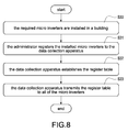
- Fig. 8 is a flowchart of installing a micro inverter according to a first embodiment of the present disclosure.
- the required micro inverters 1 are installed in a building (S30), that is the corresponding solar panels 2 and DC-to-AC converters 3 are installed.
- the administrator registers the installed micro inverters 1 to the data collection apparatus 6 (S31) so that the data collection apparatus 6 realizes the information of the all micro inverters 1 installed in the building.
- the data collection apparatus 6 establishes the register table T1 (S32) and stores the register table T1.
- the data collection apparatus 6 transmits the register table T1 to all of the micro inverters 1 (S33). Accordingly, the data collection apparatus 6 can realize that the amount of the micro inverters 1 connected to the power line 4 by inquiring the register table T1.
- the micro inverters 1 can communicate to each other according to the recorded information of the register table T1.
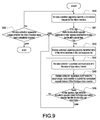
- Fig. 9 is a flowchart of the inquiry action according to a second embodiment of the present disclosure.
- the data collection apparatus 6 can submit a connection request to the micro inverters 1 through the power line 4 (S40) to confirm operation conditions of the micro inverters 1. Afterward, it is to judge whether the data collection apparatus 6 receives the connection responses transmitted from the micro inverters 1 within a predetermined time (S41). If the data collection apparatus 6 receives the connection responses transmitted from the micro inverters 1 within a predetermined time, the micro inverters 1 are regarded as the second-type micro inverters. Afterward, the data collection apparatus 6 judges whether the micro inverters have been completely inquired (S42). If the micro inverters have not been completely inquired, the step (S40) is re-executed to submit another connection request to another micro inverter 1.
- the micro inverters 1 are regarded as the first-type micro inverters.
- the data collection apparatus 6 can record the information of the micro inverters 1 in the non-response list 642 (S43).
- the data collection apparatus 6 communicates with the second-type micro inverter that is one of the micro inverters 1 (S44), and commands the second-type micro inverter to submit the connection request instead of the first-type micro inverter (S45).
- the second-type micro inverter is provided to receive the response transmitted from the first-type micro inverter, and transmit the received response to the data collection apparatus 6.
- the data collection apparatus 6 judges whether the data collection apparatus 6 receives the first-type micro inverter's response transmitted from the second-type micro inverter (S46). If the data collection apparatus 6 receives the first-type micro inverter's response transmitted from the second-type micro inverter, the data collection apparatus 6 continues commanding the second-type micro inverter to submit the connection request to another micro inverter 1.
- the step (S44) is re-executed because the second-type micro inverter cannot communicate with the first-type micro inverter, that is, the data collection apparatus 6 searches another second-type micro inverter to re-submit the connection request to the first-type micro inverter.
- the data collection apparatus 6 can judge that the first-type micro inverter is faulted when the second-type micro inverter does not receive the response transmitted from the first-type micro inverter within the determined time. Thereinafter, a simple embodiment is exemplified for further demonstration.
- Fig. 10 is a flowchart of the inquiry action according to a third embodiment of the present disclosure.
- the data collection apparatus 6 first reads the non-response list 642 (S50) and realizes that the third micro inverter 13 is the first-type micro inverter according to the non-response list 642.
- the data collection apparatus 6 commands the second micro inverter 12 to submit the connection request instead of the third micro inverter 13 (S51).
- the second micro inverter 12 because the second micro inverter 12 has responded the connection request submitted from the data collection apparatus 6, the second micro inverter 12 is regarded as the second-type micro inverter.
- the second micro inverter 12 receives the command transmitted from the data collection apparatus 6 (S52) and submits the connection request to the third micro inverter 13 according to the command (S53). After the third micro inverter 13 receives the connection request submitted from the second micro inverter 12 (S54), the third micro inverter 13 immediately replies the request contents to the second micro inverter 12 (S55). Afterward, the second micro inverter 12 receives the response transmitted from the third micro inverter 13 (S56) and replies the response to the data collection apparatus 6 (S57). After the data collection apparatus 6 receives the response replied from the second micro inverter 12 (S58), the inquiry procedure is finished (S59).
- the third micro inverter 13 cannot receive the connection request submitted from the second micro inverter 12, it indicates that too far distance or too much interference, such as the harmonic pollution generated due to excessive electrical apparatuses 7 is between the second micro inverter 12 and the third micro inverter 13.
- the data collection apparatus 6 would search another second-type micro inverter to replace the second micro inverter 12 and communicate with the third micro inverter 13.
- the third micro inverter 13 is probably faulted when the second micro inverter 12 does not receive the response transmitted from the third micro inverter 13 after the second micro inverter 12 submits the connection require.
- Fig. 11 is a flowchart of data collection according to a first embodiment of the present disclosure.
- the data collection apparatus 6 can sequentially submits the data request to the micro inverters 1 after confirming conditions of the micro inverters 1 (S70) so as to collect the information of the total power generating capacity or the power generating efficiency of the solar panel 2.
- the data collection apparatus 6 judges whether the operated micro inverter 1 is the second-type micro inverter or not (S71) by inquiring the non-response list 642. If the operated micro inverter 1 is the second-type micro inverter, the data collection apparatus 6 directly receives the data replied from the second-type micro inverter through the power line 4 (S72). Afterward, the data collection apparatus 6 judges whether all data of the micro inverter 1 have been completely collected (S73). If all data of the micro inverter 1 have not been completely collected, the step (S70) is re-executed to submit another data request to the next micro inverter 1.
- the data collection apparatus 6 inquires the non-response list 642 (S74) to search another second-type micro inverter and communicate with the second-type micro inverter (S75). Afterward, the data collection apparatus 6 commands the second-type micro inverter to submit the data request instead of the first-type micro inverter (S76).
- the data collection apparatus 6 judges whether the data collection apparatus 6 receives the data of the first-type micro inverter replied by the second-type micro inverter (S77). If the data collection apparatus 6 receives the data of the first-type micro inverter, the data collection apparatus 6 continues submitting the data request to another micro inverter 1. If the data collection apparatus 6 does not receive the data of the first-type micro inverter, the step (S74) is re-executed because the second-type micro inverter cannot communicate with the first-type micro inverter or the first-type micro inverter is faulted, that is, the data collection apparatus 6 searches another second-type micro inverter to re-submit the data request to the first-type micro inverter. Thereinafter, a simple embodiment is exemplified for further demonstration.
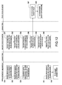
- Fig. 12 is a flowchart of data collection according to a second embodiment of the present disclosure.
- the data collection apparatus 6 realizes that the second micro inverter 12 is the second-type micro inverter and the third micro inverter 13 is the first-type micro inverter according to the non-response list 642.
- the data collection apparatus 6 submits the data request to the second micro inverter 12 (S80).
- the second micro inverter 12 receives the data request submitted from the data collection apparatus 6 (S81).
- the data collection apparatus 6 has submitted the data request to the first micro inverter 11 and received the data replied from the first micro inverter 11, but not limited.
- the second micro inverter 12 After receiving the data request, the second micro inverter 12 starts to collect and process data according to the request contents and replies the corresponding data to the data collection apparatus 6 through the power line 4 (S82). Afterward, the data collection apparatus 6 can receive the data replied from the second micro inverter 12 though the power line 4 (S83).
- the data collection apparatus 6 commands the second micro inverter 12 to submit the data request instead of the third micro inverter 13 (S84) when collecting the data of the third micro inverter 13.
- the second micro inverter 12 receives the command transmitted from the data collection apparatus 6 (S85) and submits the data request to the third micro inverter 13 according to the received command (S86).
- the third micro inverter 13 receives the request through the power line (S87), collects and processes the corresponding data according to the request contents, and replies the collected and processed data to the second micro inverter 12 (S88).
- the second micro inverter 12 receives the data replied from the third micro inverter 13 through the power line 4 (S89) and replies the received data to the data collection apparatus 6 instead of the third micro inverter 13 (S90). After the data collection apparatus 6 receives the data replied from the second micro inverter 12 (S91), the data request procedure is finished (S92).
- the data collection apparatus 6 can search and find at least one second-type micro inverter to replace the first-type micro inverter that cannot communicate with the data collection apparatus 6 because of the too far distance or too much interference is between the data collection apparatus 6 and the first-type micro inverter. Accordingly, the second-type micro inverter adjacent or near the first-type micro inverter is provided to play a role of the relay apparatus between the data collection apparatus 6 and the first-type micro inverter so as to fully extend available distance of the power line 4, completely collect data of the all registered micro inverters 1, and significantly reduce the influence of the electrical apparatuses 7.
Landscapes
- Engineering & Computer Science (AREA)
- Power Engineering (AREA)
- Computer Networks & Wireless Communication (AREA)
- Signal Processing (AREA)
- Inverter Devices (AREA)
- Supply And Distribution Of Alternating Current (AREA)
Abstract
A power line communication (PLC) routing system includes a plurality of micro inverters (1) and a data collection apparatus (6) connected to the micro inverters (1) through a power line (4). After being installed in the building, the micro inverters (1) are registered to the data collection apparatus (6). When submitting a connection request to the micro inverters (1) but cannot receive the corresponding response, the data collection apparatus (6) commands a micro inverter (1) which has responded the request to transmit the request to another micro inverter (1) which is out of time to response, and re-transmits data from the another micro inverter (1) to the data collection apparatus (6).
Description
- The present disclosure relates generally to a power line communication system, and more particularly to a power line communication routing system and a method of operating the same.
- In general, the solar power system outputs the electricity generated from the solar panels through the power line. Also, additional data transmission lines connected to the solar panels are used to transmit the data of the solar panels, such as the total power generating capacity or power generating efficiency of the solar panels.
- Because the solar panels are usually installed outdoors to achieve the optimal rate of receiving light sources, the above-mentioned data transmission lines would inevitably expose outside the building. The heat-resistant and water-proof materials are appropriate for the data transmission lines in order to provide better transmission quality through the data transmission lines, however, that increases the costs of the solar power system. In addition, it is not easy to store the superfluous data transmission lines and it is not good looking.
- Today an improved solar power system is implemented by using the power line communication (PLC) technology to output the electricity generated from the solar panels and the data of the solar panels.
- However, the same power line is usually connected to different large electrical apparatuses, such as the refrigerator, air conditioner, television, washing machine, computer, and so on. Once the length of the power line is too long, the amount of the electrical apparatuses connected to the power line is too much, or the unstable voltage caused by the old electrical apparatuses, it is easy to cause the harmonic pollution in the power line so that the solar panels cannot correctly communicate with external apparatuses and transmit data to each other. Also, the transmitted data are distorted because of the harmonic pollution even if the solar panels can correctly transmit data through the power line.
- An object of the present disclosure is to provide a power line communication routing system and a method of operating the same that can overcome problems of incorrect commands and data transmission due to the too far distance or too much interference when a power line is provided to simultaneously transmit electricity, commands, and data.
- In order to achieve the above-mentioned object, a power line communication (PLC) routing system is provided; the PLC routing system includes a plurality of micro inverters and a data collection apparatus. The micro inverters are connected to the data collection apparatus through the power line to transmit electricity, commands, and data. After the micro inverters are installed in a building, the micro inverters register to the data collection apparatus. When the data collection apparatus submits a connection request to the micro inverters and cannot acquire the corresponding responses, the data collection apparatus commands the micro inverter which has received the response to submit the request instead of the micro inverter which does not reply the response within a timeout period. The micro inverter transmits the response to the data collection apparatus after receiving the replied data.
- As mentioned above, the data collection apparatus cannot communicate with the micro inverters through the power line when too far distance between the micro inverter and the data collection apparatus or too much interference, such as the harmonic pollution generated due to excessive electrical apparatuses. The present disclosure has following features and advantages. The micro inverters connected to the power line can communicate to each other so that another micro inverter can be used to submit the request once the data collection apparatus cannot communicate with one of the micro inverters. Accordingly, the data collection apparatus can continuously submit the request to the micro inverter and normally receives the data replied from the micro inverter when the data collection apparatus cannot directly communicate with the micro inverter.
- In other words, the PLC routing system and the method are provided to overcome problems of incorrect commands and data transmission due to the too far distance or too much interference when a power line is provided to simultaneously transmit electricity, commands, and data.
- It is to be understood that both the foregoing general description and the following detailed description are exemplary, and are intended to provide further explanation of the present disclosure as claimed. Other advantages and features of the present disclosure will be apparent from the following description, drawings and claims.
- The features of the present disclosure believed to be novel are set forth with particularity in the appended claims. The present disclosure itself, however, may be best understood by reference to the following detailed description of the present disclosure, which describes an exemplary embodiment of the present disclosure, taken in conjunction with the accompanying drawings, in which:
-
Fig. 1 is an architecture block diagram of a power line communication (PLC) routing system according to a first embodiment of the present disclosure; -
Fig. 2 is a schematic view of a first inquiry action according to the first embodiment of the present disclosure; -
Fig. 3 is a schematic view of a second inquiry action according to the first embodiment of the present disclosure; -
Fig. 4 is a flowchart of the inquiry action according to the first embodiment of the present disclosure; -
Fig. 5 is a schematic view of a third inquiry action according to the first embodiment of the present disclosure; -
Fig. 6 is a block diagram of a DC-to-AC converter according to a first embodiment of the present disclosure; -
Fig. 7 is a block diagram of a data collection apparatus according to a first embodiment of the present disclosure; -
Fig. 8 is a flowchart of installing a micro inverter according to a first embodiment of the present disclosure; -
Fig. 9 is a flowchart of the inquiry action according to a second embodiment of the present disclosure; -
Fig. 10 is a flowchart of the inquiry action according to a third embodiment of the present disclosure; -
Fig. 11 is a flowchart of data collection according to a first embodiment of the present disclosure; and -
Fig. 12 is a flowchart of data collection according to a second embodiment of the present disclosure. - Reference will now be made to the drawing figures to describe the present invention in detail.
- Reference is made to
Fig. 1 which is an architecture block diagram of a power line communication (PLC) routing system according to a first embodiment of the present disclosure. The PLC routing system mainly includes a plurality of micro inverters 1, apower line 4, and adata collection apparatus 6. The micro inverters 1 are connected to thedata collection apparatus 6 through thepower line 4 so as to transmit electricity, commands, and data. In this embodiment, thepower line 4 is a grid or an AC bus. However, the embodiment is only exemplified but is not intended to limit the scope of the disclosure. - The PLC routing system is constructed in a building, such as a house. Each of the micro inverters 1 has a
solar panel 2 and a DC-to-AC converter 3 electrically connected to thesolar panel 2. Thesolar panel 2 is usually installed on the building roof to receive external light source and generate a DC power. The DC-to-AC converter 3 receives the DC power generated from thesolar panel 2 and converts the DC power into an AC power, and the AC power is outputted through thepower line 4. Generally, all of the micro inverters 1 are connected to thepower line 4, and thepower line 4 is connected to apower company 5 so that the redundant AC power outputted from the micro inverters 1 can be fed back and sold to thepower company 5 through thepower line 4. - The
data collection apparatus 6 submits a connection request to the micro inverts 1 to confirm operation conditions of the micro inverters 1 through thepower line 4. In addition, thedata collection apparatus 6 also submits a data request to the micro inverters 1 so that the micro inverters 1 can reply the corresponding data, such as the total power generating capacity or power generating efficiency of thesolar panel 2 to thedata collection apparatus 6. - The micro inverters 1 are connected to the
power line 4 in the building, that is, the micro inverters 1 are connected to thesame power line 4 which is also connected to one or moreelectrical apparatuses 7, such as the refrigerator, air conditioner, television, computer, and so on. Thedata collection apparatus 6 cannot correctly communicate with the micro inverters 1 when the too far distance between thedata collection apparatus 6 and the micro inverters 1 or the too much interference in thepower line 4, such as the harmonic pollution generated due to excessiveelectrical apparatuses 7. - Reference is made to
Fig. 2 and Fig. 3 which are schematic views of a first inquiry action and a second inquiry action according to the first embodiment of the present disclosure, respectively. In this embodiment, the number of the micro inverters 1 is three, namely, a firstmicro inverter 11, a secondmicro inverter 12, and a thirdmicro inverter 13, but not limited. As mentioned above, the firstmicro inverter 11 has a first solar panel, the secondmicro inverter 12 has a second solar panel, and the thirdmicro inverter 13 has a third solar panel. Also, the first solar panel, the second solar panel, and the third solar panel are connected to thepower line 4 through a first DC-to-AC converter, a second DC-to-AC converter, and a third DC-to-AC converter, respectively. However, the embodiments are only exemplified but are not intended to limit the scope of the disclosure. - As shown in
Fig. 2 , thedata collection apparatus 6 submits a request to the first, second, and thirdmicro inverters data collection apparatus 6 wants to confirm operation conditions or collect relevant data of the first, second, and thirdmicro inverters data collection apparatus 6 cannot correctly communicate with the thirdmicro inverter 13 because of the too far distance between thedata collection apparatus 6 and the thirdmicro inverters 13 or the too much interference in thepower line 4. In this embodiment, even if the thirdmicro inverter 13 is not faulted, the thirdmicro inverter 13 still cannot correctly receive the request submitted from thedata collection apparatus 6 because of above-mentioned problems. - When the above-mentioned problem occurs, the third
micro inverter 13 would miss the request submitted from thedata collection apparatus 6 so that there will be no response transmitted from the thirdmicro inverter 13 to thedata collection apparatus 6. In this embodiment, thedata collection apparatus 6 can correctly receive the responses transmitted from the firstmicro inverter 11 and the secondmicro inverter 12, but the thirdmicro inverter 13 does not reply the response within a timeout period. Thereinafter, a simple embodiment is exemplified for further demonstration. - Reference is made to
Fig. 4 which is a flowchart of the inquiry action according to the first embodiment of the present disclosure. Thedata collection apparatus 6 can sequentially or randomly submits the connection request to the first, second, and thirdmicro inverters data collection apparatus 6 wants to confirm operation conditions or collect relevant data of the first, second, and thirdmicro inverters - First, the
data collection apparatus 6 submits a connection request to the firstmicro inverter 11 through the power line 4 (S10). When the firstmicro inverter 11 correctly receives the connection request (S11), the firstmicro inverter 11 transmits a connection response to thedata collection apparatus 6 through the power line 4 (S12), and then thedata collection apparatus 6 receives the connection response transmitted from the firstmicro inverter 11 through the power line 4 (S13). - Afterward, the
data collection apparatus 6 submits a connection request to the secondmicro inverter 12 through the power line 4 (S14). When the secondmicro inverter 12 correctly receives the connection request (S15), the secondmicro inverter 12 transmits a connection response to thedata collection apparatus 6 through the power line 4 (S16), and then thedata collection apparatus 6 receives the connection response transmitted from the secondmicro inverter 12 through the power line 4 (S17). Afterward, thedata collection apparatus 6 submits a connection request to the thirdmicro inverter 13 through the power line 4 (S18). However, thedata collection apparatus 6 cannot receive the response transmitted from the thirdmicro inverter 13 because of the above-mentioned problems of incorrect commands and data transmission due to the too far distance or too much interference (S19). Therefore, thedata collection apparatus 6 records the response timeout of the third micro inverter 13 (S20). In this embodiment, thedata collection apparatus 6 regards the thirdmicro inverter 13 as the first-type micro inverter when the response time of the third micro inverter exceeds a determined time. - In this embodiment, because the first-type micro inverters are the micro inverters that cannot normally communicate with the
data collection apparatus 6 due to the above-mentioned problems, the first-type micro inverters are probably faulted or in normal operation. - Reference is made to
Fig. 5 which is a schematic view of a third inquiry action according to the first embodiment of the present disclosure. Thedata collection apparatus 6 regards the micro inverter that can normally and correctly communicate with thedata collection apparatus 6 and reply the connection request as a second-type micro inverter. Thedata collection apparatus 6 commands the second-type micro inverter to submit the connection request instead of the first-type micro inverter. As shown inFig. 5 , because the secondmicro inverter 12 has responded the connection request submitted from thedata collection apparatus 6, thedata collection apparatus 6 regards the secondmicro inverter 12 as the second-type micro inverter. Thedata collection apparatus 6 commands the secondmicro inverter 12 to submit the connection request instead of the thirdmicro inverter 13, receives the response of the thirdmicro inverter 13, and transmits the response to thedata collection apparatus 6. - Generally, a distance between any two micro inverters is less than a distance between the
data collection apparatus 6 and the first-type micro inverter. That is, a distance between the second-type micro inverter and the first-type micro inverter is less than a distance between thedata collection apparatus 6 and the first-type micro inverter. - In this embodiment, the
data collection apparatus 6 can give priority to select the micro inverter that is near the first-type micro inverter within a predetermined distance and can normally communicate with thedata collection apparatus 6 as the second-type micro inverter. In the preferred embodiment, the second-type micro inverter is adjacent to the first-type micro inverter, but not limited. Especially, thedata collection apparatus 6 can judge the distance between the first-type micro inverter and the second-type micro inverter or judge whether the second-type micro inverter is adjacent to the first-type micro inverter according to the media access control address (MAC Address), the serial number (SN), the personal identification number (PIN), the internet protocol address (IP Address), or so on. However, the embodiment is only exemplified but is not intended to limit the scope of the disclosure. - Accordingly, the second-type micro inverter plays a role of a relay apparatus between the
data collection apparatus 6 and the first-type micro inverter so as to reduce the distance between the first-type micro inverter anddata collection apparatus 6, thus increasing probability of correctly receiving the connection request of the first-type micro inverter. - In another embodiment, when the
data collection apparatus 6 submits the data requires to the micro inverters 1, the first-type micro inverter cannot correctly receive the data request submitted from thedata collection apparatus 6. Therefore, thedata collection apparatus 6 is connected to the second-type micro inverter which is adjacent or closer to the first-type micro inverter, and thedata collection apparatus 6 commands the second-type micro inverter to submit the data request instead of the first-type micro inverter, also transmits the data replied from the first-type micro inverter to thedata collection apparatus 6. Simultaneously, the second-type micro inverter can directly reply the corresponding data to thedata collection apparatus 6 because the second-type micro inverter can correctly receive the data request submitted from thedata collection apparatus 6. - Reference is made to
Fig. 6 which is a block diagram of a DC-to-AC converter according to a first embodiment of the present disclosure. Each of the micro inverters 1 includes thesolar panel 2 and the DC-to-AC converter 3. As shown inFig. 6 , the DC-to-AC converter 3 has a DC-to-DC step-upmodule 31, aconversion module 32, amicroprocessor 33, and amemory 34. - The
conversion module 32 is connected to thesolar panel 2 and thepower line 4. Thesolar panel 2 generates the DC power to the DC-to-AC converter 3. The DC-to-AC converter 3 receives the DC power generated from thesolar panel 2 via theconversion module 32 and converts the DC power into the AC power, and the AC power is outputted through thepower line 4. The AC power can supply power to theelectrical apparatuses 7 connected to thepower line 4, and also the redundant AC power can be fed back and sold to thepower company 5. - The DC-to-DC step-up
module 31 electrically connected between thesolar panel 2 and theconversion module 32. The DC-to-DC step-upmodule 31 receives the DC power generated from thesolar panel 2 and boosts the DC power, and the boosted DC power is outputted to theconversion module 32 to be converted into the AC power by theconversion module 32. However, the DC-to-DC step-upmodule 31 is not necessary to be used depending on the actual demands. - The
microprocessor 33 is electrically connected to theconversion module 32 and thesolar panel 2. Themicroprocessor 33 receives the request transmitted from thepower line 4 and via theconversion module 32. In particular, the request is submitted from thedata collection apparatus 6 or the second-type micro inverter through thepower lien 4. After receiving the request, themicroprocessor 33 executes the corresponding action according to the request, such as the inquiry of the total power generating capacity or the power generating efficiency of thesolar panel 2. In addition, the inquired data are replied to thedata collection apparatus 6 or the second-type micro inverter. - The
memory 34 is electrically connected to themicroprocessor 33 and has a register table T1 therein. Each of the micro inverters 1 has to register to thedata collection apparatus 6 when the micro inverter is initially installed in the building so that thedata collection apparatus 6 realizes the total number of the micro inverters 1 installed in the building. The second-type micro inverter can inquire the register table T1 to communicate with thedata collection apparatus 6 according to the information of the first-type micro inverter when the second-type micro inverter receives the command transmitted from thedata collection apparatus 6. - Reference is made to
Fig. 7 which is a block diagram of a data collection apparatus according to a first embodiment of the present disclosure. In this embodiment, thedata collection apparatus 6 mainly includes asignal transmission unit 61, amicrocontroller unit 62, atransmission unit 63, and amemory 64. Thesignal transmission unit 61 is provided to connect to thepower line 4 so that thedata collection apparatus 6 submits the request to the micro inverters 1 and receives the response transmitted from the micro inverters 1 through thepower line 4. - The
microcontroller unit 62 is electrically connected to thesignal transmission unit 61 to control the data collection apparatus producing and submitting the request, and also process the data received by thesignal transmission unit 61. In this embodiment, themicrocontroller unit 62 can produce and submit the request to provide the total power generating capacity or the power generating efficiency according to setting values or the operation of the administrator. - The
transmission unit 63 is electrically connected to themicrocontroller unit 62, and thedata collection apparatus 6 is externally connected to aterminal apparatus 8 through thetransmission unit 63. In this embodiment as shown inFig. 7 , thetransmission unit 63 is wirelessly connected to theterminal apparatus 8. However, the embodiment is only exemplified but is not intended to limit the scope of the disclosure, that is, thetransmission unit 63 can be also physically (wirely) connected to theterminal apparatus 8. Theterminal apparatus 8 can be a wireless access point (AP) so that thedata collection apparatus 6 can be connected to theterminal apparatus 8 through thetransmission unit 63, and connected to a network through theterminal apparatus 8. Accordingly, the administrator can operate thedata collection apparatus 6 through the network so as to register the micro inverters 1 to thedata collection apparatus 6, enable thedata collection apparatus 6 to submit the request, and access the collected data by thedata collection apparatus 6. - The
memory 64 is electrically connected to themicrocontroller unit 62, and thememory 64 is provided to store the inquired data replied from the micro inverters 1. In addition, thememory 64 has an embeddedweb 641. The embeddedweb 641 is provided to receive the login information of the administrator when the administrator uses the computer to connect to thedata collection apparatus 6 through the network so that the administrator can operate the embeddedweb 641 to register the micro inverters 1. Thedata collection apparatus 6 provides the register table T1 according to the registered results and the register table T1 is stored in thememory 64. - Especially, after the register table T1 in the
memory 64 is established in thedata collection apparatus 6, the register table T1 is transmitted to the micro inverters 1 through thepower line 4 and stored in thememory 34 of the DC-to-AC converter 3. Accordingly, the second-type micro inverter instead of thedata collection apparatus 6 can inquire the information of the first-type micro inverter and communicate with the first-type micro inverter according to the register table T1 therein. - In particular, when the administrator registers the micro inverters 1, the media access control address (MAC Address), the serial number (SN), the personal identification number (PIN), the internet protocol address (IP Address), or so on are recorded in the
data collection apparatus 6 so that thedata collection apparatus 6 can produce the register table T1 according the recorded information. Accordingly, thedata collection apparatus 6 can realize that the amount of the micro inverters 1 connected to thepower line 4, where the micro inverters 1 are located, and how to connect to and communicate with the micro inverters 1 by inquiring the register table T1. - As mentioned above, the information of the first-type micro inverter, such as the MAC Address, the SN, the PIN, the IP Address, or so on is recorded to produce a
non-response list 642. Thenon-response list 642 is stored in thememory 64. Thedata collection apparatus 6 can inquire thenon-response list 642 to judge which micro inverters 1 are the first-type micro inverter. Accordingly, it is to determine whether the second-type micro inverter needs to be used to submit the data request or not. - Reference is made to
Fig. 8 which is a flowchart of installing a micro inverter according to a first embodiment of the present disclosure. First, the required micro inverters 1 are installed in a building (S30), that is the correspondingsolar panels 2 and DC-to-AC converters 3 are installed. - Afterward, the administrator registers the installed micro inverters 1 to the data collection apparatus 6 (S31) so that the
data collection apparatus 6 realizes the information of the all micro inverters 1 installed in the building. According to the registered results, thedata collection apparatus 6 establishes the register table T1 (S32) and stores the register table T1. Afterward, thedata collection apparatus 6 transmits the register table T1 to all of the micro inverters 1 (S33). Accordingly, thedata collection apparatus 6 can realize that the amount of the micro inverters 1 connected to thepower line 4 by inquiring the register table T1. In addition, the micro inverters 1 can communicate to each other according to the recorded information of the register table T1. - Reference is made to
Fig. 9 which is a flowchart of the inquiry action according to a second embodiment of the present disclosure. When the register process is successfully completed, thedata collection apparatus 6 can submit a connection request to the micro inverters 1 through the power line 4 (S40) to confirm operation conditions of the micro inverters 1. Afterward, it is to judge whether thedata collection apparatus 6 receives the connection responses transmitted from the micro inverters 1 within a predetermined time (S41). If thedata collection apparatus 6 receives the connection responses transmitted from the micro inverters 1 within a predetermined time, the micro inverters 1 are regarded as the second-type micro inverters. Afterward, thedata collection apparatus 6 judges whether the micro inverters have been completely inquired (S42). If the micro inverters have not been completely inquired, the step (S40) is re-executed to submit another connection request to another micro inverter 1. - On the contrary, If the
data collection apparatus 6 does not receive the connection responses transmitted from the micro inverters 1 within the predetermined time, the micro inverters 1 are regarded as the first-type micro inverters. Thedata collection apparatus 6 can record the information of the micro inverters 1 in the non-response list 642 (S43). Afterward, thedata collection apparatus 6 communicates with the second-type micro inverter that is one of the micro inverters 1 (S44), and commands the second-type micro inverter to submit the connection request instead of the first-type micro inverter (S45). Finally, the second-type micro inverter is provided to receive the response transmitted from the first-type micro inverter, and transmit the received response to thedata collection apparatus 6. - The
data collection apparatus 6 judges whether thedata collection apparatus 6 receives the first-type micro inverter's response transmitted from the second-type micro inverter (S46). If thedata collection apparatus 6 receives the first-type micro inverter's response transmitted from the second-type micro inverter, thedata collection apparatus 6 continues commanding the second-type micro inverter to submit the connection request to another micro inverter 1. If thedata collection apparatus 6 does not receive the first-type micro inverter's response transmitted from the second-type micro inverter, the step (S44) is re-executed because the second-type micro inverter cannot communicate with the first-type micro inverter, that is, thedata collection apparatus 6 searches another second-type micro inverter to re-submit the connection request to the first-type micro inverter. In another embodiment, thedata collection apparatus 6 can judge that the first-type micro inverter is faulted when the second-type micro inverter does not receive the response transmitted from the first-type micro inverter within the determined time. Thereinafter, a simple embodiment is exemplified for further demonstration. - Reference is made to
Fig. 10 which is a flowchart of the inquiry action according to a third embodiment of the present disclosure. Thedata collection apparatus 6 first reads the non-response list 642 (S50) and realizes that the thirdmicro inverter 13 is the first-type micro inverter according to thenon-response list 642. Thedata collection apparatus 6 commands the secondmicro inverter 12 to submit the connection request instead of the third micro inverter 13 (S51). In this embodiment, because the secondmicro inverter 12 has responded the connection request submitted from thedata collection apparatus 6, the secondmicro inverter 12 is regarded as the second-type micro inverter. - The second
micro inverter 12 receives the command transmitted from the data collection apparatus 6 (S52) and submits the connection request to the thirdmicro inverter 13 according to the command (S53). After the thirdmicro inverter 13 receives the connection request submitted from the second micro inverter 12 (S54), the thirdmicro inverter 13 immediately replies the request contents to the second micro inverter 12 (S55). Afterward, the secondmicro inverter 12 receives the response transmitted from the third micro inverter 13 (S56) and replies the response to the data collection apparatus 6 (S57). After thedata collection apparatus 6 receives the response replied from the second micro inverter 12 (S58), the inquiry procedure is finished (S59). - Especially, if the third
micro inverter 13 cannot receive the connection request submitted from the secondmicro inverter 12, it indicates that too far distance or too much interference, such as the harmonic pollution generated due to excessiveelectrical apparatuses 7 is between the secondmicro inverter 12 and the thirdmicro inverter 13. Once a timeout of replying the response to thedata collection apparatus 6 occurs, thedata collection apparatus 6 would search another second-type micro inverter to replace the secondmicro inverter 12 and communicate with the thirdmicro inverter 13. In addition, the thirdmicro inverter 13 is probably faulted when the secondmicro inverter 12 does not receive the response transmitted from the thirdmicro inverter 13 after the secondmicro inverter 12 submits the connection require. - Reference is made to
Fig. 11 which is a flowchart of data collection according to a first embodiment of the present disclosure. Thedata collection apparatus 6 can sequentially submits the data request to the micro inverters 1 after confirming conditions of the micro inverters 1 (S70) so as to collect the information of the total power generating capacity or the power generating efficiency of thesolar panel 2. - Afterward, the
data collection apparatus 6 judges whether the operated micro inverter 1 is the second-type micro inverter or not (S71) by inquiring thenon-response list 642. If the operated micro inverter 1 is the second-type micro inverter, thedata collection apparatus 6 directly receives the data replied from the second-type micro inverter through the power line 4 (S72). Afterward, thedata collection apparatus 6 judges whether all data of the micro inverter 1 have been completely collected (S73). If all data of the micro inverter 1 have not been completely collected, the step (S70) is re-executed to submit another data request to the next micro inverter 1. - In the step (S71), if the operated micro inverter 1 is the first-type micro inverter, the
data collection apparatus 6 inquires the non-response list 642 (S74) to search another second-type micro inverter and communicate with the second-type micro inverter (S75). Afterward, thedata collection apparatus 6 commands the second-type micro inverter to submit the data request instead of the first-type micro inverter (S76). - After the step (S76), the
data collection apparatus 6 judges whether thedata collection apparatus 6 receives the data of the first-type micro inverter replied by the second-type micro inverter (S77). If thedata collection apparatus 6 receives the data of the first-type micro inverter, thedata collection apparatus 6 continues submitting the data request to another micro inverter 1. If thedata collection apparatus 6 does not receive the data of the first-type micro inverter, the step (S74) is re-executed because the second-type micro inverter cannot communicate with the first-type micro inverter or the first-type micro inverter is faulted, that is, thedata collection apparatus 6 searches another second-type micro inverter to re-submit the data request to the first-type micro inverter. Thereinafter, a simple embodiment is exemplified for further demonstration. - Reference is made to
Fig. 12 which is a flowchart of data collection according to a second embodiment of the present disclosure. In this embodiment, thedata collection apparatus 6 realizes that the secondmicro inverter 12 is the second-type micro inverter and the thirdmicro inverter 13 is the first-type micro inverter according to thenon-response list 642. First, thedata collection apparatus 6 submits the data request to the second micro inverter 12 (S80). Afterward, the secondmicro inverter 12 receives the data request submitted from the data collection apparatus 6 (S81). In particular, before the step (S80), thedata collection apparatus 6 has submitted the data request to the firstmicro inverter 11 and received the data replied from the firstmicro inverter 11, but not limited. - After receiving the data request, the second
micro inverter 12 starts to collect and process data according to the request contents and replies the corresponding data to thedata collection apparatus 6 through the power line 4 (S82). Afterward, thedata collection apparatus 6 can receive the data replied from the secondmicro inverter 12 though the power line 4 (S83). - Because the third
micro inverter 13 is regarded as the first-type micro inverter, thedata collection apparatus 6 commands the secondmicro inverter 12 to submit the data request instead of the third micro inverter 13 (S84) when collecting the data of the thirdmicro inverter 13. The secondmicro inverter 12 receives the command transmitted from the data collection apparatus 6 (S85) and submits the data request to the thirdmicro inverter 13 according to the received command (S86). Afterward, the thirdmicro inverter 13 receives the request through the power line (S87), collects and processes the corresponding data according to the request contents, and replies the collected and processed data to the second micro inverter 12 (S88). - The second
micro inverter 12 receives the data replied from the thirdmicro inverter 13 through the power line 4 (S89) and replies the received data to thedata collection apparatus 6 instead of the third micro inverter 13 (S90). After thedata collection apparatus 6 receives the data replied from the second micro inverter 12 (S91), the data request procedure is finished (S92). - In the present disclosure, the
data collection apparatus 6 can search and find at least one second-type micro inverter to replace the first-type micro inverter that cannot communicate with thedata collection apparatus 6 because of the too far distance or too much interference is between thedata collection apparatus 6 and the first-type micro inverter. Accordingly, the second-type micro inverter adjacent or near the first-type micro inverter is provided to play a role of the relay apparatus between thedata collection apparatus 6 and the first-type micro inverter so as to fully extend available distance of thepower line 4, completely collect data of the all registered micro inverters 1, and significantly reduce the influence of theelectrical apparatuses 7.
Claims (15)
- A power line communication routing system comprising:- a power line (4);- a plurality of micro inverters (1) connected to the power line (4), each micro inverter (1) having a solar panel (2) and a DC-to-AC converter (3); the DC-to-AC converter (3) electrically connected to the solar panel (2) and the power line (4), and configured to output an AC power through the power line (4); and- a data collection apparatus (6) connected to the power line (4), and configured to submit requests to the micro inverters (1) and receive responses transmitted from the micro inverters (1);- wherein the data collection apparatus (6) is configured to regard the micro inverter (1) as a first-type micro inverter when the micro inverter (1) does not submit the response within a predetermined time, and command a second-type micro inverter of the micro inverters (1) to submit the request instead of the first-type micro inverter; the second-type micro inverter is configured to receive the data replied from the first-type micro inverter through the power line (4), and transmit the received data to the data collection apparatus (6) through the power line (4).
- The power line communication routing system in claim 1, wherein the data collection apparatus (6) is configured to regard to micro inverter (1) that normally replies the request and is near the first-type micro inverter within a predetermined distance as the second-type micro inverter.
- The power line communication routing system in claim 2, wherein the second-type micro inverter is adjacent to the first-type micro inverter.
- The power line communication routing system in claim 2, wherein the DC-to-AC converter (3) comprising:- a conversion module (32) connected to the solar panel (2) and the power line (4), and configured to receive a DC power generated from the solar panel (2), convert the DC power into the AC power, and output the AC power through the power line (4);- a microprocessor (33) electrically connected to the conversion module (32) and the solar panel (2), and configured to receive the request transmitted from the power line (4), inquire the relevant data of the solar panel (2) according to the received request, and reply the inquired data to the data collection apparatus (6) through the power line (4); and- a DC-to-DC step-up module (31) electrically connected between the solar panel (2) and the conversion module (32), and configured to receive the DC power generated from the solar panel (2), boost the DC power, and output the boosted DC power to the conversion module (32).
- The power line communication routing system in claim 4, wherein the data collection apparatus (6) comprising:- a signal transmission unit (61) connected to the power line (4), and configured to transmit the request and receive the data replied from the micro inverters (1);- a microcontroller unit (62) electrically connected to the signal transmission unit (61), and configured to control the data collection apparatus (6) producing and submitting the request and process the data received by the signal transmission unit (61); and- a memory (64) electrically connected to the microcontroller unit (62), and configured to store the data replied from the micro inverters (1).
- The power line communication routing system in claim 5, wherein the memory (64) has an embedded web (641) configured to receive the login information of the administrator and register the micro inverters (1), and the data collection apparatus (6) is configured to produce a register table (T1) according to the registered results and store the register table (T1) in the memory (64).
- The power line communication routing system in claim 6, wherein the data collection apparatus (6) is configured to transmit the register table (T1) to the micro inverters (1) and store the register table (T1) in the micro inverters (1) through the power line (4), and the second-type micro inverter is configured to inquire the information of the first-type micro inverter according to the register table (T1) and submit the request instead of the firs-type micro inverter.
- The power line communication routing system in claim 6, wherein the data collection apparatus (6) is configured to record the information of the first-type micro inverter and produce a non-response list (642), wherein the non-response list (642) is stored in the memory (64), and the data collection apparatus (6) is configured to inquire the non-response list (642) to judge which micro inverters (1) are the first-type micro inverter when the data collection apparatus (6) is configured to submit the request.
- A method of operating a power line communication routing system applied in a building, a power line (4), a plurality of micro inverters (1), and a data collection apparatus (6) installed in a building, wherein each micro inverter (1) comprises a solar panel (2) and a DC-to-AC converter (3) connected to the solar panel (2), and the micro inverters (1) are connected to the data collection apparatus (6) through the power line (4); the method comprising following steps:(a) submitting a connection request to one of the micro inverters (1) by the data collection apparatus (6) through the power line (4);(b) judging whether a response transmitted from the micro inverter (1) is received by the data collection apparatus (6) within a predetermined time;(c) regarding the micro inverter (1) as a first-type micro inverter when the data collection apparatus (6) does not receive the response;(d) communicating with a second-type micro inverter of the micro inverters (1) and commanding the second-type micro inverter to submit the connection request instead of the first-type micro inverter after the step (c); wherein the second-type micro inverter has responded the connection request submitted from the data collection apparatus (6);(e) receiving the response transmitted from the first-type micro inverter by the second-type micro inverter; and(f) transmitting the response to the data collection apparatus (6) by the second-type micro inverter.
- The method of operating the power line communication routing system in claim 9, further comprising:(g) recording the information of the first-type micro inverter in a non-response list (642) after the step (c), wherein the non-response list (642) is stored in a memory (64) of the data collection apparatus (6).
- The method of operating the power line communication routing system in claim 10, further comprising:(h) submitting a data request to one of the micro inverters (1) by the data collection apparatus (6) through the power line (4);(i) judging whether the micro inverter (1) is the second-type micro inverter;;(j) directly receiving the data replied from the second-type micro inverter by the data collection apparatus (6) through the power line (4) when the micro inverter (1) is the second-type micro inverter;(k) communicating with the second-type micro inverter by the data collection apparatus (6) and commanding the second-type micro inverter to submit the data request instead of the first-type micro inverter when the micro inverter (1) is the first-type micro inverter;(1) receiving the data replied from the first-type micro inverter by the second-type micro inverter through the power line (4); and(m) transmitting the data to the data collection apparatus (6) by the second-type micro inverter.
- The method of operating the power line communication routing system in claim 11, wherein the data collection apparatus (6) is configured to judge whether the micro inverter (1) is the second-type micro inverter or the first-type micro inverter by inquiring the non-response list (642) in step (i).
- The method of operating the power line communication routing system in claim 12, wherein before the step (a) comprising following steps:(a01) installing a plurality of micro inverters (1) in the building;(a02) registering the micro inverters (1) to the data collection apparatus (6) according to the information of the micro inverters (1);(a03) establishing a register table (T1) by the data collection apparatus (6) according to the registered results; and(a04) transmitting the register table (T1) to the micro inverters (1) and storing the register table (T1) in the micro inverters (1) by the data collection apparatus (6) through the power line (4); wherein in the steps (e) and (m), the second-type micro inverter is configured to inquire the information of the first-type micro inverter according to the register table (T1), and submit the inquiry and request instead of the firs-type micro inverter.
- A power line communication routing system comprising:- a power line (4);- two solar panels (2) configured to receive external light sources and generate electricity;- two DC-to-AC converters (3) connected to the two solar panels (2) to form two micro inverters (1), the two micro inverters (1) connected to the power line (4) via the DC-to-AC converters (3) to output AC powers through the power line (4); and- a data collection apparatus (6) connected to the power line (4), and connected to the two micro inverters (1) through the power line (4) and configured to submit a request to the two micro inverters (1) and receive the data replied from the two micro inverters (1);- wherein the two micro inverters (1) include a first-type micro inverter and a second-type micro inverter; the second-type micro inverter is the micro inverter (1) that can normally reply the request within the determined time, and the first-type micro inverter is that micro inverter (1) that cannot reply the request within the determined time; the data collection apparatus (6) is configured to command the second-type micro inverter to submit the request instead of the first-type micro inverter when the data collection apparatus (6) is configured to collect the data of the first-type micro inverter; the second-type micro inverter is configured to submit the request to the first-type micro inverter, receive the data replied from the first-type micro inverter, and transmit the received data to the data collection apparatus (6) through the power line (4).
- The power line communication routing system in claim 14, wherein the data collection apparatus (6) has a memory (64) and the memory (64) has an embedded web (641); the embedded web (641) is configured to receive the login information of the administrator and register the two micro inverters (1); the data collection apparatus (6) is configured to produce a register table (T1) according to the registered results and store the register table (T1) in the memory (64); the data collection apparatus (6) is configured to transmit the register table (T1) to the two micro inverters (1) and store the register table (T1) in the two micro inverters (1) through the power line (4); the second-type micro inverter is configured to inquire the information of the first-type micro inverter according to the register table (T1) and submit the request instead of the first-type micro inverter.
Applications Claiming Priority (1)
| Application Number | Priority Date | Filing Date | Title |
|---|---|---|---|
| CN201310237977.0A CN104244467A (en) | 2013-06-13 | 2013-06-13 | Power line routing system and routing method thereof |
Publications (1)
| Publication Number | Publication Date |
|---|---|
| EP2814185A1 true EP2814185A1 (en) | 2014-12-17 |
Family
ID=49911261
Family Applications (1)
| Application Number | Title | Priority Date | Filing Date |
|---|---|---|---|
| EP20130198713 Withdrawn EP2814185A1 (en) | 2013-06-13 | 2013-12-20 | Method and apparatus for routing power line communication |
Country Status (3)
| Country | Link |
|---|---|
| US (1) | US20140368047A1 (en) |
| EP (1) | EP2814185A1 (en) |
| CN (1) | CN104244467A (en) |
Families Citing this family (5)
| Publication number | Priority date | Publication date | Assignee | Title |
|---|---|---|---|---|
| CN105743136B (en) * | 2014-12-11 | 2017-12-22 | 南京南瑞继保电气有限公司 | Suppress the method that multiple current conversion stations enter Passive Shape Control pattern under a kind of island state |
| US10466282B2 (en) * | 2015-07-27 | 2019-11-05 | Sunpower Corporation | Solar energy metering, communications, and control system |
| KR102444149B1 (en) * | 2017-10-12 | 2022-09-15 | 엘지전자 주식회사 | Photovoltaic module, photovoltaic system, and method for operating the same |
| CN108923994A (en) * | 2018-09-10 | 2018-11-30 | 珠海格力电器股份有限公司 | Communication fault detection method and device |
| CN210007670U (en) * | 2019-05-23 | 2020-01-31 | 台达电子企业管理(上海)有限公司 | Photovoltaic power optimization system |
Citations (2)
| Publication number | Priority date | Publication date | Assignee | Title |
|---|---|---|---|---|
| US20120089260A1 (en) * | 2010-10-11 | 2012-04-12 | Solarbridge Technologies, Inc. | System and method for establishing communication with an array of inverters |
| WO2012120906A1 (en) * | 2011-03-10 | 2012-09-13 | パナソニック株式会社 | Power line communication device, power line communication system, power line communication method, and power line communication program |
Family Cites Families (13)
| Publication number | Priority date | Publication date | Assignee | Title |
|---|---|---|---|---|
| US7248490B2 (en) * | 2004-06-17 | 2007-07-24 | Gaia Power Technologies, Inc. | Battery and inverter configuration with increased efficiency |
| US7852207B2 (en) * | 2006-02-14 | 2010-12-14 | Current Technologies, Llc | Method for establishing power line communication link |
| KR101205279B1 (en) * | 2006-03-23 | 2012-11-27 | 엔페이즈 에너지, 인코포레이티드 | Method and apparatus for converting direct current to alternating current |
| TWI380553B (en) * | 2009-04-16 | 2012-12-21 | Delta Electronics Inc | Power supply and power system employing plural power supplies |
| US7913181B2 (en) * | 2009-10-26 | 2011-03-22 | General Electric Company | Method and apparatus for monitoring a power system |
| TWI432951B (en) * | 2010-12-01 | 2014-04-01 | Delta Electronics Inc | Power supply and power system employing plural power supplies |
| TWI424658B (en) * | 2011-03-16 | 2014-01-21 | 台達電子工業股份有限公司 | Solar inverter and solar inverter control method |
| TW201349731A (en) * | 2012-05-30 | 2013-12-01 | 台達電子工業股份有限公司 | Solar power generation system with power generation module and output power control method thereof |
| US9276635B2 (en) * | 2012-06-29 | 2016-03-01 | Sunpower Corporation | Device, system, and method for communicating with a power inverter using power line communications |
| CN103023791B (en) * | 2012-11-30 | 2015-10-28 | 泰华智慧产业集团股份有限公司 | A kind of dynamic routing method |
| US9755430B2 (en) * | 2013-04-11 | 2017-09-05 | Solantro Semiconductor Corp. | Virtual inverter for power generation units |
| CN104242701B (en) * | 2013-06-13 | 2017-06-16 | 台达电子工业股份有限公司 | DC-AC converter, micro inverter and solar system thereof |
| TW201513541A (en) * | 2013-09-26 | 2015-04-01 | 台達電子工業股份有限公司 | Micro inverter of solar power generation system and operation method thereof |
-
2013
- 2013-06-13 CN CN201310237977.0A patent/CN104244467A/en active Pending
- 2013-12-17 US US14/108,427 patent/US20140368047A1/en not_active Abandoned
- 2013-12-20 EP EP20130198713 patent/EP2814185A1/en not_active Withdrawn
Patent Citations (2)
| Publication number | Priority date | Publication date | Assignee | Title |
|---|---|---|---|---|
| US20120089260A1 (en) * | 2010-10-11 | 2012-04-12 | Solarbridge Technologies, Inc. | System and method for establishing communication with an array of inverters |
| WO2012120906A1 (en) * | 2011-03-10 | 2012-09-13 | パナソニック株式会社 | Power line communication device, power line communication system, power line communication method, and power line communication program |
Also Published As
| Publication number | Publication date |
|---|---|
| CN104244467A (en) | 2014-12-24 |
| US20140368047A1 (en) | 2014-12-18 |
Similar Documents
| Publication | Publication Date | Title |
|---|---|---|
| US12132317B2 (en) | Method and apparatus for provisioning an alternative energy source generator | |
| US9843358B2 (en) | Device, system, and method for communicating with a power inverter using power line communications | |
| US20140368047A1 (en) | Power line communication routing system and method of operating the same | |
| JP5247883B2 (en) | Power conversion system and communication address setting method | |
| US11799418B2 (en) | Method, apparatus, and system for obtaining electronic layout applied to photovoltaic array | |
| JP2010186795A (en) | Photoelectric cell device and method for determining failure | |
| CN104242701B (en) | DC-AC converter, micro inverter and solar system thereof | |
| US11419175B2 (en) | Reconstructing a personal area network or system after a failure in the network or system | |
| US12159288B2 (en) | Methods and apparatus for maintaining a power conversion system | |
| EP4510532B1 (en) | Device and method for identifying physical location of battery pack, and method for addressing during photovoltaic power station start-up | |
| CN118214965B (en) | 4G collector meter searching and reading method and device, computer equipment and storage medium | |
| CN105159109A (en) | A PLC controller remote upgrade system | |
| KR102957721B1 (en) | Photovoltaic power generation system, mlpe registration device and method | |
| JP7036067B2 (en) | Control methods and programs for photovoltaic power generation systems, photovoltaic power generation processing equipment, and photovoltaic power generation processing equipment | |
| CN113137825A (en) | Intelligent refrigerator assembly recognition system and method | |
| KR20220040685A (en) | Solar panel monitoring system, inverter including the same, and solar panel with solar panel monitoring device and monitoring method | |
| KR20180034921A (en) | Analytical System of Photovoltaic Power Generation for House and Service Method using thereof | |
| US20240162744A1 (en) | Method and apparatus for identifying distributed energy resource systems located behind a transformer within utility grid infrastructure | |
| CN114693234A (en) | Battery swapping processing method and system for battery swapping station, computer equipment and storage medium | |
| CN113986299B (en) | Device upgrading method, device, device to be upgraded, and system | |
| WO2025245972A1 (en) | Fault point position detection method in power system, and power system | |
| KR20200077314A (en) | Monitoring system for solar power plant | |
| CN113709842B (en) | Method, system, controller and power distribution field area network for data transmission scheduling | |
| CN115830771A (en) | Integrated charging method, device, equipment and medium | |
| JP2018207706A (en) | Power management system, device, reception method, program |
Legal Events
| Date | Code | Title | Description |
|---|---|---|---|
| 17P | Request for examination filed |
Effective date: 20131220 |
|
| AK | Designated contracting states |
Kind code of ref document: A1 Designated state(s): AL AT BE BG CH CY CZ DE DK EE ES FI FR GB GR HR HU IE IS IT LI LT LU LV MC MK MT NL NO PL PT RO RS SE SI SK SM TR |
|
| AX | Request for extension of the european patent |
Extension state: BA ME |
|
| PUAI | Public reference made under article 153(3) epc to a published international application that has entered the european phase |
Free format text: ORIGINAL CODE: 0009012 |
|
| STAA | Information on the status of an ep patent application or granted ep patent |
Free format text: STATUS: THE APPLICATION IS DEEMED TO BE WITHDRAWN |
|
| 18D | Application deemed to be withdrawn |
Effective date: 20150618 |