EP2814179A2 - Flow imaging - Google Patents
Flow imaging Download PDFInfo
- Publication number
- EP2814179A2 EP2814179A2 EP14172010.2A EP14172010A EP2814179A2 EP 2814179 A2 EP2814179 A2 EP 2814179A2 EP 14172010 A EP14172010 A EP 14172010A EP 2814179 A2 EP2814179 A2 EP 2814179A2
- Authority
- EP
- European Patent Office
- Prior art keywords
- signal
- analogue
- static
- slow moving
- components
- Prior art date
- Legal status (The legal status is an assumption and is not a legal conclusion. Google has not performed a legal analysis and makes no representation as to the accuracy of the status listed.)
- Ceased
Links
Images



Classifications
-
- G—PHYSICS
- G06—COMPUTING OR CALCULATING; COUNTING
- G06T—IMAGE DATA PROCESSING OR GENERATION, IN GENERAL
- G06T5/00—Image enhancement or restoration
- G06T5/50—Image enhancement or restoration using two or more images, e.g. averaging or subtraction
-
- G—PHYSICS
- G01—MEASURING; TESTING
- G01N—INVESTIGATING OR ANALYSING MATERIALS BY DETERMINING THEIR CHEMICAL OR PHYSICAL PROPERTIES
- G01N29/00—Investigating or analysing materials by the use of ultrasonic, sonic or infrasonic waves; Visualisation of the interior of objects by transmitting ultrasonic or sonic waves through the object
- G01N29/02—Analysing fluids
-
- G—PHYSICS
- G01—MEASURING; TESTING
- G01N—INVESTIGATING OR ANALYSING MATERIALS BY DETERMINING THEIR CHEMICAL OR PHYSICAL PROPERTIES
- G01N29/00—Investigating or analysing materials by the use of ultrasonic, sonic or infrasonic waves; Visualisation of the interior of objects by transmitting ultrasonic or sonic waves through the object
- G01N29/44—Processing the detected response signal, e.g. electronic circuits specially adapted therefor
- G01N29/4463—Signal correction, e.g. distance amplitude correction [DAC], distance gain size [DGS], noise filtering
-
- G—PHYSICS
- G06—COMPUTING OR CALCULATING; COUNTING
- G06T—IMAGE DATA PROCESSING OR GENERATION, IN GENERAL
- G06T5/00—Image enhancement or restoration
- G06T5/70—Denoising; Smoothing
-
- H—ELECTRICITY
- H03—ELECTRONIC CIRCUITRY
- H03M—CODING; DECODING; CODE CONVERSION IN GENERAL
- H03M1/00—Analogue/digital conversion; Digital/analogue conversion
- H03M1/12—Analogue/digital converters
- H03M1/124—Sampling or signal conditioning arrangements specially adapted for A/D converters
- H03M1/129—Means for adapting the input signal to the range the converter can handle, e.g. limiting, pre-scaling ; Out-of-range indication
- H03M1/1295—Clamping, i.e. adjusting the DC level of the input signal to a predetermined value
-
- H—ELECTRICITY
- H03—ELECTRONIC CIRCUITRY
- H03M—CODING; DECODING; CODE CONVERSION IN GENERAL
- H03M1/00—Analogue/digital conversion; Digital/analogue conversion
- H03M1/12—Analogue/digital converters
- H03M1/18—Automatic control for modifying the range of signals the converter can handle, e.g. gain ranging
-
- H—ELECTRICITY
- H04—ELECTRIC COMMUNICATION TECHNIQUE
- H04N—PICTORIAL COMMUNICATION, e.g. TELEVISION
- H04N25/00—Circuitry of solid-state image sensors [SSIS]; Control thereof
- H04N25/70—SSIS architectures; Circuits associated therewith
- H04N25/76—Addressed sensors, e.g. MOS or CMOS sensors
- H04N25/78—Readout circuits for addressed sensors, e.g. output amplifiers or A/D converters
-
- G—PHYSICS
- G06—COMPUTING OR CALCULATING; COUNTING
- G06T—IMAGE DATA PROCESSING OR GENERATION, IN GENERAL
- G06T2207/00—Indexing scheme for image analysis or image enhancement
- G06T2207/10—Image acquisition modality
- G06T2207/10132—Ultrasound image
-
- G—PHYSICS
- G06—COMPUTING OR CALCULATING; COUNTING
- G06T—IMAGE DATA PROCESSING OR GENERATION, IN GENERAL
- G06T2207/00—Indexing scheme for image analysis or image enhancement
- G06T2207/20—Special algorithmic details
- G06T2207/20212—Image combination
- G06T2207/20224—Image subtraction
Definitions
- the present invention relates to flow imaging, in particular to suppression of echoes from stationary or slow moving reflections in an image.
- Flow of media through a conduit may be imaged by transmitting waves such as ultrasound waves into the conduit and detecting echoes reflected from the flowing media and the surrounding structure.
- waves such as ultrasound waves into the conduit
- echoes from stationary or slow moving reflecting acoustic boundaries in the system such as pipe walls, blood vessels, tissue structures etc are far stronger than those from the flowing or time varying media such as water, oil, blood etc.
- the stationary or slow moving echoes may for example be 100 times larger than the echoes from the flowing media such that it is very difficult to precisely determine data for the flowing media.
- the signal for the static or slow moving reflections is generally cancelled in the digital domain by digitally subtracting the static or slow moving element from the digitized incoming signal, as shown for example in EP 0 947 853 .
- the resolution of the analogue-to-digital converter is used to digitize the portion of the incoming signal relating to the flowing media of interest, for example 1%.
- the extent to which the combined analogue signal can be amplified prior to analogue-to-digital conversion is limited by the need not to clip the static element, which has the flowing data of interest superimposed upon it, so that data is not lost.
- a high resolution analogue-to-digital converter is sometimes used but this can be very expensive and often comprises the sampling rate possible.
- a system suitable for reducing static or slow moving echoes from an image comprising:
- Subtracting the static or slow moving component from the incoming measured signal in the analogue domain allows a resultant analogue difference signal to be produced corresponding to the flowing media of interest.
- This analogue signal corresponding to the flowing media of interest may then be amplified to a much greater degree without being clipped by the analogue-to-digital converter, producing a far better signal to noise ratio in the subsequently processed and displayed signal.
- An amplifier with a controllable gain may be provided to receive the subtracted analogue signal corresponding to the flow components of the signal so that the extent to which the signal is amplified is dependent upon its gain setting. Controlling the gain of the amplifier enables the input range of the analogue-to-digital converter to be more fully utilised for more precise results.
- An imaging system may be provided including a transducer array, a transmitter, a receiver, an output for a display and the system for reducing static and slow moving echoes from an image of the first aspect of the present invention.
- the system could be provided in the receiver or form part of a controller for the imaging system for example.
- a method for reducing static or slow moving echoes from an image comprising digitizing an incoming analogue signal from a detector, separating the static or slow moving components of the digitized signal, converting the separated static or slow moving components into an analogue signal and subtracting the analogue version of the static or slow moving components from an analogue signal received from detector to produce an analogue signal corresponding to the flow components of the image.
- FIG 1 shows a conduit 1 which may, for example, be a tube or pipe such as a portion of a pipeline, a water pipe, a blood vessel or artery.
- the conduit 1 is arranged to convey a flowing or time varying media such as water, oil, gas or mixtures thereof or bodily fluids such as blood.
- Particles or bubbles 2 within the flowing media produce echoes when a transmitting/receiving transducer 3 of an imaging system is used to form an image of the flowing media.
- echoes from the walls of the conduit 1 produce time-static or slow moving (for example due to temperature variations in the conduit) echoes which are much larger than the echoes produced by the flowing media 2.
- the echoes form the conduit 1 may be even larger due to multiple reflections within the conduit 1.
- These static or slow moving echoes may be typically 100 times larger than echoes from the flowing media such that any imaging produced from the flowing media 2 is only seen at a very low resolution.
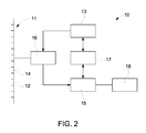
- FIG 2 shows an example of an imaging system 10 suitable for producing images of a flowing media 2.
- the imaging system 10 uses ultrasonic waves but any suitable signal may be used such as magnetic, optical, thermal, electrical impedance, sound waves or microwaves for example.
- the imaging system 10 of this example has a transducer array 11 comprising a plurality of transducer elements 12, each of which may be separately driven and each of which produces a burst of ultrasonic energy when energised by a pulsed waveform produced by a transmitter 13.
- the ultrasonic energy reflected back to the transducer array 11 from a flowing media such as shown in FIG 1 is converted to an electrical signal by a receiving transducer element 14 which may be in the same transmitting transducer array 11 or a separate receiving transducer.
- the electrical signals from the receiving transducer elements 14 are applied to a receiver 15 through a set of transmit/receive switches 16.
- the transmit/receive switches 16 are typically semiconductors which protect the receive electronics from the high voltages generated by the transmit electronics.
- the transmit signal causes the semiconductor protection to limit the signal to the receiver 15.
- the transmitter 13 and receiver 15 may be operated under the control of a synchronizing controller 17.
- a scan may be performed by acquiring a series of echoes in which the transmitter 13 is gated ON momentarily to energise each transmitting transducer element 12 and the subsequent echo signals produced by each receiving transducer element are applied to the receiver 15.
- the receiver 15 combines the separate echo signals from each transducer element to produce a single echo signal which is used to produce a line in an image which may be provided on a display monitor 18.
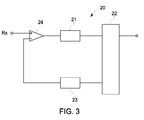
- FIG 3 shows an example of a system illustrating the invention suitable for reducing or substantially removing the static or slow moving echoes from an image.
- the system 20 includes an analogue-to-digital converter 21 for digitising a received analogue signal from a detector 11 via the node Rx.
- Means 22 is provided for digitally separating the static or slow moving component from the digitised signal from the analogue-to-digital converter 21. Any suitable separator 22 may be used such as a low pass filter, a decimation filter or the use of an appropriate software function in a suitable processor for example to provide the static or slow moving components of the signal.
- a digital-to-analogue converter 23 is provided to receive the separated static or slow moving components of the signal and provide an analogue version of the separated static or slow moving components of the signal.
- a subtractor 24 is then used to subtract the analogue version of the static or slow moving components of the signal provided by digital-to-analogue convertor 23 from the analogue input provided by a transducer from node Rx to produce an analogue signal corresponding to the remaining flow components of the signal.
- the resultant signal represents echoes from the flowing media 2 and is digitised 21 and may be displayed 18.
- a resultant analogue difference signal corresponding to the flowing media of interest is produced which has a much higher signal to noise ratio.
- the signal with the much higher signal to noise ratio may then be processed to provide a far higher resolution measurement and image of the flowing media 2.
- One or more of the components of the system 21, 22, 23, 24, such as the digital-to-analogue converter 23 is preferably arranged to operate at an appropriate sample rate such that it seeks a sample value at appropriate time points or acquisition windows that leads to a net zero static or slow moving signal at the analogue-to-digital converter 21.
- An algorithm may be used to separate the static or slow moving components of the signal. The algorithm may be adaptive and dependent upon the processing time of the other relevant components in the circuit, in particular the separator 22, the digital-to-analogue convertor 23 and the subtractor 24 to overcome any latency offset issues or time-based echo drift.
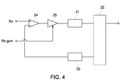
- Figure 4 shows a more detailed example of the system of figure 3 and includes an amplifier 25.
- the gain of the amplifier 25 may be controlled by an input labelled Rx Gain.
- the gain of the amplifier 25 may be controlled either manually by an operator or by a controller to more fully utilise the input range of the analogue-to-digital convertor 21 for more precise results even though the peak to peak size or magnitude of the analogue signal corresponding to the flow components may vary. This provides even further enhanced signal to noise ratios giving even more precise results.
- the function of the amplifier could be included in another component of the system, such as the analogue-to-digital converter 21.
- Figure 5 illustrates an example of a signal that may be received by a conventional prior art imaging system.
- the signal is dominated by the static or slow moving elements produced by echoes from conduit walls.
- the first static or slow moving sine wave 30 corresponds to echoes from the near wall 1 in Figure 1 and the later static or slow moving sine wave 31 corresponds to echoes from the far wall.
- the echoes from flowing or time-varying media within a conduit can be seen superimposed on the static or slow moving signal and account for only a very small proportion of the overall signal amplitude.
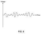
- figure 6 shows an example of the analogue signal output by the subtractor 24 in the example of figure 3 or figure 4 of our description.
- the removal of the slow moving or static elements 30 from figure 5 produce a signal corresponding to the flowing or time-varying media within a conduit with a significantly enhanced signal to noise ratio which when displayed provides a far more precise image of the flowing component.
- Figure 7 shows a flow diagram of a method of reducing or removing static or slow moving echoes from a signal, in particular when the static or slow moving echoes are substantially larger than the portion of the signal which is to be displayed.
- an incoming analogue signal from a detector is digitized.
- the static or slow moving components of the digitized signal are separated. The separation may be provided in any suitable way, for example by using a low pass filter, a decimation filter or by a processor.
- the separated static or slow moving components of the signal are converted into an analogue signal.
- the analogue version of the static or slow moving components of the signal are subtracted from an analogue signal received from the detector to produce an analogue signal corresponding to the flow components of the signal.
- the resultant subtracted signal may then be amplified, digitized, possibly subjected to further processing and may then be displayed.
- the gain of any amplification may be varied depending upon the magnitude of the resultant subtracted signal to more fully utilize the input range of the analogue-to-digital converter.
- the components shown in figures 2 , 3 and 4 may be provided by any suitable electronic hardware or by software provided on a processor or computer for example.
- the separator 22 may be provided by any appropriate component such as a low pass filter a decimation filter or by the use of an appropriate software function in a suitable processor or computer.
Landscapes
- Engineering & Computer Science (AREA)
- Theoretical Computer Science (AREA)
- Physics & Mathematics (AREA)
- General Physics & Mathematics (AREA)
- General Health & Medical Sciences (AREA)
- Immunology (AREA)
- Life Sciences & Earth Sciences (AREA)
- Chemical & Material Sciences (AREA)
- Analytical Chemistry (AREA)
- Biochemistry (AREA)
- Signal Processing (AREA)
- Health & Medical Sciences (AREA)
- Pathology (AREA)
- Acoustics & Sound (AREA)
- Multimedia (AREA)
- Ultra Sonic Daignosis Equipment (AREA)
- Measurement Of Velocity Or Position Using Acoustic Or Ultrasonic Waves (AREA)
- Investigating Or Analyzing Materials By The Use Of Ultrasonic Waves (AREA)
- Closed-Circuit Television Systems (AREA)
- Analogue/Digital Conversion (AREA)
Abstract
Description
- The present invention relates to flow imaging, in particular to suppression of echoes from stationary or slow moving reflections in an image.
- Flow of media through a conduit, such as fluid through a pipe or blood through a blood vessel for example, may be imaged by transmitting waves such as ultrasound waves into the conduit and detecting echoes reflected from the flowing media and the surrounding structure. However, a problem with such imaging is that echoes from stationary or slow moving reflecting acoustic boundaries in the system such as pipe walls, blood vessels, tissue structures etc are far stronger than those from the flowing or time varying media such as water, oil, blood etc. The stationary or slow moving echoes may for example be 100 times larger than the echoes from the flowing media such that it is very difficult to precisely determine data for the flowing media.
- In order to more precisely determine the data for the flowing media, the signal for the static or slow moving reflections is generally cancelled in the digital domain by digitally subtracting the static or slow moving element from the digitized incoming signal, as shown for example in
EP 0 947 853 . However, because of the very large difference between the magnitude of the signal from the static or slow moving reflections and the signal for the flowing media, for example 100:1, only a very small proportion of the resolution of the analogue-to-digital converter is used to digitize the portion of the incoming signal relating to the flowing media of interest, for example 1%. Furthermore, the extent to which the combined analogue signal can be amplified prior to analogue-to-digital conversion is limited by the need not to clip the static element, which has the flowing data of interest superimposed upon it, so that data is not lost. A high resolution analogue-to-digital converter is sometimes used but this can be very expensive and often comprises the sampling rate possible. - It would be desirable to be able to reduce or remove the portion of a signal relating to echoes from static or slow moving reflecting acoustic boundaries in an image whilst overcoming or reducing one or more of the problems explained above.
- According to a first aspect of the present invention, there is provided a system suitable for reducing static or slow moving echoes from an image, the system comprising:
- an analogue-to-digital converter for digitizing a received analogue signal from a detector;
- means for digitally separating static or slow moving components of the digital signal;
- a digital-to-analogue converter to provide an analogue version of the separated static or slow moving components of the signal and
- a subtractor to subtract the analogue version of the static or slow moving components of the signal from an analogue signal received from a detector to produce an analogue signal corresponding to the remaining flow components of the signal.
- Subtracting the static or slow moving component from the incoming measured signal in the analogue domain allows a resultant analogue difference signal to be produced corresponding to the flowing media of interest. This analogue signal corresponding to the flowing media of interest may then be amplified to a much greater degree without being clipped by the analogue-to-digital converter, producing a far better signal to noise ratio in the subsequently processed and displayed signal.
- An amplifier with a controllable gain may be provided to receive the subtracted analogue signal corresponding to the flow components of the signal so that the extent to which the signal is amplified is dependent upon its gain setting. Controlling the gain of the amplifier enables the input range of the analogue-to-digital converter to be more fully utilised for more precise results.
- An imaging system may be provided including a transducer array, a transmitter, a receiver, an output for a display and the system for reducing static and slow moving echoes from an image of the first aspect of the present invention. The system could be provided in the receiver or form part of a controller for the imaging system for example.
- According to a second aspect of the present invention, there is provided a method for reducing static or slow moving echoes from an image, the method comprising digitizing an incoming analogue signal from a detector, separating the static or slow moving components of the digitized signal, converting the separated static or slow moving components into an analogue signal and subtracting the analogue version of the static or slow moving components from an analogue signal received from detector to produce an analogue signal corresponding to the flow components of the image.
- Examples of the present invention will now be described, by way of example only, with reference to the accompanying drawings in which:
-
FIG 1 illustrates flow of media through a conduit; -
FIG 2 shows an example of an imaging system which may be used with an example of the present invention; -
FIG 3 shows an example of a system illustrating our invention for reducing static or slow moving echoes from an image; -
FIG 4 shows a more detailed example of a system illustrating the present invention; -
FIG 5 shows an example a typical received signal from a prior art imaging system; -
FIG 6 shows an example of a received signal using an example of a system of the present invention; -
FIG 7 is a flow diagram of a method illustrating the present invention. -
FIG 1 shows aconduit 1 which may, for example, be a tube or pipe such as a portion of a pipeline, a water pipe, a blood vessel or artery. Theconduit 1 is arranged to convey a flowing or time varying media such as water, oil, gas or mixtures thereof or bodily fluids such as blood. Particles orbubbles 2 within the flowing media produce echoes when a transmitting/receivingtransducer 3 of an imaging system is used to form an image of the flowing media. However, echoes from the walls of theconduit 1 produce time-static or slow moving (for example due to temperature variations in the conduit) echoes which are much larger than the echoes produced by the flowingmedia 2. The echoes form theconduit 1 may be even larger due to multiple reflections within theconduit 1. These static or slow moving echoes may be typically 100 times larger than echoes from the flowing media such that any imaging produced from the flowingmedia 2 is only seen at a very low resolution. -
FIG 2 shows an example of animaging system 10 suitable for producing images of a flowingmedia 2. In this example theimaging system 10 uses ultrasonic waves but any suitable signal may be used such as magnetic, optical, thermal, electrical impedance, sound waves or microwaves for example. Theimaging system 10 of this example has atransducer array 11 comprising a plurality oftransducer elements 12, each of which may be separately driven and each of which produces a burst of ultrasonic energy when energised by a pulsed waveform produced by atransmitter 13. The ultrasonic energy reflected back to thetransducer array 11 from a flowing media such as shown inFIG 1 is converted to an electrical signal by a receivingtransducer element 14 which may be in the same transmittingtransducer array 11 or a separate receiving transducer. The electrical signals from thereceiving transducer elements 14 are applied to areceiver 15 through a set of transmit/receiveswitches 16. The transmit/receiveswitches 16 are typically semiconductors which protect the receive electronics from the high voltages generated by the transmit electronics. The transmit signal causes the semiconductor protection to limit the signal to thereceiver 15. Thetransmitter 13 andreceiver 15 may be operated under the control of a synchronizingcontroller 17. - A scan may be performed by acquiring a series of echoes in which the
transmitter 13 is gated ON momentarily to energise each transmittingtransducer element 12 and the subsequent echo signals produced by each receiving transducer element are applied to thereceiver 15. Thereceiver 15 combines the separate echo signals from each transducer element to produce a single echo signal which is used to produce a line in an image which may be provided on adisplay monitor 18. -
FIG 3 shows an example of a system illustrating the invention suitable for reducing or substantially removing the static or slow moving echoes from an image. Thesystem 20 includes an analogue-to-digital converter 21 for digitising a received analogue signal from adetector 11 via the node Rx.Means 22 is provided for digitally separating the static or slow moving component from the digitised signal from the analogue-to-digital converter 21. Anysuitable separator 22 may be used such as a low pass filter, a decimation filter or the use of an appropriate software function in a suitable processor for example to provide the static or slow moving components of the signal. A digital-to-analogue converter 23 is provided to receive the separated static or slow moving components of the signal and provide an analogue version of the separated static or slow moving components of the signal. Asubtractor 24 is then used to subtract the analogue version of the static or slow moving components of the signal provided by digital-to-analogue convertor 23 from the analogue input provided by a transducer from node Rx to produce an analogue signal corresponding to the remaining flow components of the signal. The resultant signal represents echoes from the flowingmedia 2 and is digitised 21 and may be displayed 18. As the static or slow moving component of the incoming measured signal is subtracted in the analogue domain, a resultant analogue difference signal corresponding to the flowing media of interest is produced which has a much higher signal to noise ratio. The signal with the much higher signal to noise ratio may then be processed to provide a far higher resolution measurement and image of the flowingmedia 2. - One or more of the components of the
system analogue converter 23 is preferably arranged to operate at an appropriate sample rate such that it seeks a sample value at appropriate time points or acquisition windows that leads to a net zero static or slow moving signal at the analogue-to-digital converter 21. An algorithm may be used to separate the static or slow moving components of the signal. The algorithm may be adaptive and dependent upon the processing time of the other relevant components in the circuit, in particular theseparator 22, the digital-to-analogue convertor 23 and thesubtractor 24 to overcome any latency offset issues or time-based echo drift. -
Figure 4 shows a more detailed example of the system offigure 3 and includes anamplifier 25. In this example the gain of theamplifier 25 may be controlled by an input labelled Rx Gain. The gain of theamplifier 25 may be controlled either manually by an operator or by a controller to more fully utilise the input range of the analogue-to-digital convertor 21 for more precise results even though the peak to peak size or magnitude of the analogue signal corresponding to the flow components may vary. This provides even further enhanced signal to noise ratios giving even more precise results. The function of the amplifier could be included in another component of the system, such as the analogue-to-digital converter 21. -
Figure 5 illustrates an example of a signal that may be received by a conventional prior art imaging system. As can be seen, the signal is dominated by the static or slow moving elements produced by echoes from conduit walls. Infigure 5 the first static or slow movingsine wave 30 corresponds to echoes from thenear wall 1 inFigure 1 and the later static or slow movingsine wave 31 corresponds to echoes from the far wall. The echoes from flowing or time-varying media within a conduit can be seen superimposed on the static or slow moving signal and account for only a very small proportion of the overall signal amplitude. - In contrast,
figure 6 shows an example of the analogue signal output by thesubtractor 24 in the example offigure 3 orfigure 4 of our description. As can clearly be seen, the removal of the slow moving orstatic elements 30 fromfigure 5 produce a signal corresponding to the flowing or time-varying media within a conduit with a significantly enhanced signal to noise ratio which when displayed provides a far more precise image of the flowing component. -
Figure 7 shows a flow diagram of a method of reducing or removing static or slow moving echoes from a signal, in particular when the static or slow moving echoes are substantially larger than the portion of the signal which is to be displayed. Atstep 100 an incoming analogue signal from a detector is digitized. Atstep 200 the static or slow moving components of the digitized signal are separated. The separation may be provided in any suitable way, for example by using a low pass filter, a decimation filter or by a processor. Atstep 300 the separated static or slow moving components of the signal are converted into an analogue signal. Atstep 400 the analogue version of the static or slow moving components of the signal are subtracted from an analogue signal received from the detector to produce an analogue signal corresponding to the flow components of the signal. The resultant subtracted signal may then be amplified, digitized, possibly subjected to further processing and may then be displayed. The gain of any amplification may be varied depending upon the magnitude of the resultant subtracted signal to more fully utilize the input range of the analogue-to-digital converter. - The examples described above are able to provide a signal corresponding to the flowing or time-varying fluid within a conduit which is very clear and precise without having to use large and expensive components.
- Many variations may be made to the examples described above whilst still falling within the present invention. For example, the components shown in
figures 2 ,3 and4 may be provided by any suitable electronic hardware or by software provided on a processor or computer for example. Furthermore, theseparator 22 may be provided by any appropriate component such as a low pass filter a decimation filter or by the use of an appropriate software function in a suitable processor or computer.
Claims (9)
- A system (20) suitable for reducing static or slow moving echoes in an image, the system comprising:an analogue-to-digital converter (21) for digitizing a received analogue signal from a detector;means (22) for digitally separating static or slow moving components of the digital signal;a digital-to-analogue converter (23) to provide an analogue version of the separated static or slow moving components of the signal anda subtractor (24) to subtract the analogue version of the static or slow moving components of the signal from an analogue signal received from a detector to produce an analogue signal corresponding to the remaining flow components of the signal.
- A system according to claim 1 including an amplifier with a controllable gain to receive the analogue signal corresponding to the flow components of the signal.
- A system according the claim 2 wherein the gain of the amplifier is controlled in dependence upon the magnitude of the received signal.
- A system according to any preceding claim, means for digitally separating static or slow moving components of the digital signal is controlled in dependence upon the processing time of other components in the system.
- An imaging system including a transducer array,
one or more transmitters,
one or more receivers, and
a system for reducing static or slow moving echoes from an image according to any one of the preceding claims. - An imaging system according to claim 5, further comprising an output for a display.
- A method for reducing static or slow moving echoes from an image, the method comprising:digitizing an incoming analogue signal from a detector;separating the static or slow moving components of the digitized signal;converting the separated static or slow moving components into an analogue signal; andsubtracting the analogue version of the static or slow moving components from an analogue signal received from a detector to produce an analogue signal corresponding to the flow components of the image.
- A method according to claim 7, wherein the resultant subtracted signal is amplified.
- A method according to claim 8, wherein with the gain of amplification is variable depending upon the magnitude of the resultant subtracted signal.
Applications Claiming Priority (1)
| Application Number | Priority Date | Filing Date | Title |
|---|---|---|---|
| GB1310526.7A GB2515073B (en) | 2013-06-13 | 2013-06-13 | Imaging or analysis of flowing media |
Publications (2)
| Publication Number | Publication Date |
|---|---|
| EP2814179A2 true EP2814179A2 (en) | 2014-12-17 |
| EP2814179A3 EP2814179A3 (en) | 2015-03-04 |
Family
ID=48876204
Family Applications (1)
| Application Number | Title | Priority Date | Filing Date |
|---|---|---|---|
| EP14172010.2A Ceased EP2814179A3 (en) | 2013-06-13 | 2014-06-11 | Flow imaging |
Country Status (6)
| Country | Link |
|---|---|
| US (1) | US9805453B2 (en) |
| EP (1) | EP2814179A3 (en) |
| JP (1) | JP2015002557A (en) |
| CN (1) | CN104237893B (en) |
| BR (1) | BR102014012715A2 (en) |
| GB (1) | GB2515073B (en) |
Families Citing this family (1)
| Publication number | Priority date | Publication date | Assignee | Title |
|---|---|---|---|---|
| JP6580915B2 (en) | 2015-09-14 | 2019-09-25 | キヤノンメディカルシステムズ株式会社 | Ultrasonic diagnostic apparatus and signal processing apparatus |
Citations (3)
| Publication number | Priority date | Publication date | Assignee | Title |
|---|---|---|---|---|
| US4324258A (en) * | 1980-06-24 | 1982-04-13 | Werner Huebscher | Ultrasonic doppler flowmeters |
| US4975885A (en) * | 1988-09-30 | 1990-12-04 | Siemens Aktiengesellschaft | Digital input stage for an ultrasound apparatus |
| US20070236374A1 (en) * | 2006-03-31 | 2007-10-11 | Brueske Daniel E | Universal ultrasound sigma-delta receiver path |
Family Cites Families (10)
| Publication number | Priority date | Publication date | Assignee | Title |
|---|---|---|---|---|
| DE3836823A1 (en) * | 1988-10-28 | 1990-05-03 | Olympia Aeg | Device and method for increasing the resolution in the analogue/digital conversion of signals with a DC component |
| JPH05137717A (en) * | 1991-11-20 | 1993-06-01 | Matsushita Electric Ind Co Ltd | Beamformer of ultrasonic diagnostic equipment |
| DE59800051D1 (en) | 1997-03-21 | 1999-12-30 | Flowtec Ag | Measuring and operating circuit of a Coriolis mass flow meter |
| US6074348A (en) | 1998-03-31 | 2000-06-13 | General Electric Company | Method and apparatus for enhanced flow imaging in B-mode ultrasound |
| US6267725B1 (en) * | 1999-09-13 | 2001-07-31 | General Electric Company | Individual channel analog wall filtering to improve flow sensitivity in ultrasound imaging |
| DE10048419C2 (en) * | 2000-09-29 | 2003-07-24 | Infineon Technologies Ag | Offset-free analog-digital converter |
| KR100548132B1 (en) | 2004-07-02 | 2006-02-02 | 삼성전자주식회사 | DC offset correction device and method of receiver in multiband-hopping communication system |
| US8847578B2 (en) | 2011-07-20 | 2014-09-30 | Texas Instruments Incorporated | Ambient noise cancellation in pulsed input system |
| US8712716B2 (en) * | 2011-07-29 | 2014-04-29 | Olympus Ndt Inc. | Circuitry for measuring and compensating phase and amplitude differences in NDT/NDI operation |
| JP2013063159A (en) * | 2011-09-16 | 2013-04-11 | Fujifilm Corp | Ultrasonograph and ultrasonic image generation method |
-
2013
- 2013-06-13 GB GB1310526.7A patent/GB2515073B/en not_active Expired - Fee Related
-
2014
- 2014-05-27 BR BRBR102014012715-1A patent/BR102014012715A2/en active Search and Examination
- 2014-06-04 JP JP2014115340A patent/JP2015002557A/en active Pending
- 2014-06-10 US US14/300,250 patent/US9805453B2/en not_active Expired - Fee Related
- 2014-06-11 EP EP14172010.2A patent/EP2814179A3/en not_active Ceased
- 2014-06-13 CN CN201410264359.XA patent/CN104237893B/en not_active Expired - Fee Related
Patent Citations (3)
| Publication number | Priority date | Publication date | Assignee | Title |
|---|---|---|---|---|
| US4324258A (en) * | 1980-06-24 | 1982-04-13 | Werner Huebscher | Ultrasonic doppler flowmeters |
| US4975885A (en) * | 1988-09-30 | 1990-12-04 | Siemens Aktiengesellschaft | Digital input stage for an ultrasound apparatus |
| US20070236374A1 (en) * | 2006-03-31 | 2007-10-11 | Brueske Daniel E | Universal ultrasound sigma-delta receiver path |
Also Published As
| Publication number | Publication date |
|---|---|
| GB2515073A (en) | 2014-12-17 |
| GB201310526D0 (en) | 2013-07-24 |
| US9805453B2 (en) | 2017-10-31 |
| US20140369624A1 (en) | 2014-12-18 |
| GB2515073B (en) | 2017-12-13 |
| BR102014012715A2 (en) | 2015-07-21 |
| CN104237893A (en) | 2014-12-24 |
| CN104237893B (en) | 2019-03-15 |
| EP2814179A3 (en) | 2015-03-04 |
| JP2015002557A (en) | 2015-01-05 |
Similar Documents
| Publication | Publication Date | Title |
|---|---|---|
| KR101120791B1 (en) | Ultrasound system and method for performing adaptive clutter filtering | |
| KR100459616B1 (en) | Ultrasonic diagnostic apparatus and method for measuring human tissue velocities using doppler effect | |
| US7098669B2 (en) | Depth determining system | |
| JP2008232861A (en) | Active sonar system, reception signal processing method for sonar, and signal processing program therefor | |
| JP5840868B2 (en) | Frequency detection method and apparatus | |
| KR101406806B1 (en) | Ultrasound system and method for providing ultrasound image | |
| JP6166255B2 (en) | Ultrasonic diagnostic apparatus and noise reduction method thereof | |
| WO2014062605A4 (en) | Intentional aliasing of ultrasound to downconvert to audio tones | |
| KR20120000312A (en) | Underwater acoustic detection system and its acoustic detection method | |
| CN104995530B (en) | Subject information acquisition device and subject information acquisition method | |
| US9805453B2 (en) | Flow imaging | |
| JP2011191142A (en) | Signal processor, radar apparatus, method of processing signal, and signal processing program | |
| KR101517751B1 (en) | Ultrasound system and signal filtering method | |
| CN111007519B (en) | Signal detection system, signal processing method and related detection module thereof | |
| Hu et al. | Design and implementation of high frequency ultrasound pulsed-wave Doppler using FPGA | |
| CN101856242A (en) | Doppler imaging method and Doppler imaging device for pulse waves | |
| JP5996694B2 (en) | Ultrasonic diagnostic equipment | |
| JP3642834B2 (en) | Ultrasonic Doppler diagnostic device | |
| EP3320449B1 (en) | Signal processing for a cable locating instrument | |
| KR20200137983A (en) | Pulse and continuous wave radar transceiver | |
| KR101182963B1 (en) | Ultrasound system and method for providing doppler sound | |
| US12298388B2 (en) | Target detection device and target detection method | |
| JP2718686B2 (en) | Analog-to-digital converter | |
| JPH0779976A (en) | Ultrasonic diagnostic apparatus | |
| JPH0515535A (en) | Ultrasonic Doppler imaging device |
Legal Events
| Date | Code | Title | Description |
|---|---|---|---|
| 17P | Request for examination filed |
Effective date: 20140611 |
|
| AK | Designated contracting states |
Kind code of ref document: A2 Designated state(s): AL AT BE BG CH CY CZ DE DK EE ES FI FR GB GR HR HU IE IS IT LI LT LU LV MC MK MT NL NO PL PT RO RS SE SI SK SM TR |
|
| AX | Request for extension of the european patent |
Extension state: BA ME |
|
| PUAI | Public reference made under article 153(3) epc to a published international application that has entered the european phase |
Free format text: ORIGINAL CODE: 0009012 |
|
| PUAL | Search report despatched |
Free format text: ORIGINAL CODE: 0009013 |
|
| AK | Designated contracting states |
Kind code of ref document: A3 Designated state(s): AL AT BE BG CH CY CZ DE DK EE ES FI FR GB GR HR HU IE IS IT LI LT LU LV MC MK MT NL NO PL PT RO RS SE SI SK SM TR |
|
| AX | Request for extension of the european patent |
Extension state: BA ME |
|
| RIC1 | Information provided on ipc code assigned before grant |
Ipc: H03M 1/12 20060101AFI20150128BHEP |
|
| R17P | Request for examination filed (corrected) |
Effective date: 20150904 |
|
| RBV | Designated contracting states (corrected) |
Designated state(s): AL AT BE BG CH CY CZ DE DK EE ES FI FR GB GR HR HU IE IS IT LI LT LU LV MC MK MT NL NO PL PT RO RS SE SI SK SM TR |
|
| STAA | Information on the status of an ep patent application or granted ep patent |
Free format text: STATUS: EXAMINATION IS IN PROGRESS |
|
| 17Q | First examination report despatched |
Effective date: 20180917 |
|
| STAA | Information on the status of an ep patent application or granted ep patent |
Free format text: STATUS: THE APPLICATION HAS BEEN REFUSED |
|
| 18R | Application refused |
Effective date: 20201224 |