EP2814164A2 - A multiphase ac power converter and method for controlling a multiphase ac power converter - Google Patents
A multiphase ac power converter and method for controlling a multiphase ac power converter Download PDFInfo
- Publication number
- EP2814164A2 EP2814164A2 EP14171958.3A EP14171958A EP2814164A2 EP 2814164 A2 EP2814164 A2 EP 2814164A2 EP 14171958 A EP14171958 A EP 14171958A EP 2814164 A2 EP2814164 A2 EP 2814164A2
- Authority
- EP
- European Patent Office
- Prior art keywords
- multiphase
- power converter
- reference value
- load
- controller
- Prior art date
- Legal status (The legal status is an assumption and is not a legal conclusion. Google has not performed a legal analysis and makes no representation as to the accuracy of the status listed.)
- Granted
Links
- 238000000034 method Methods 0.000 title claims abstract description 12
- 230000007935 neutral effect Effects 0.000 claims abstract description 32
- 239000003990 capacitor Substances 0.000 description 4
- 238000007667 floating Methods 0.000 description 4
- 230000002265 prevention Effects 0.000 description 3
- 238000013461 design Methods 0.000 description 2
- 230000000694 effects Effects 0.000 description 2
- 238000012360 testing method Methods 0.000 description 2
- 239000013598 vector Substances 0.000 description 2
- 238000013459 approach Methods 0.000 description 1
- 230000001419 dependent effect Effects 0.000 description 1
- 238000002955 isolation Methods 0.000 description 1
- 239000011159 matrix material Substances 0.000 description 1
- 238000005259 measurement Methods 0.000 description 1
- 230000000116 mitigating effect Effects 0.000 description 1
- 230000000737 periodic effect Effects 0.000 description 1
- 238000004088 simulation Methods 0.000 description 1
- 230000003068 static effect Effects 0.000 description 1
- 230000009466 transformation Effects 0.000 description 1
- 230000001052 transient effect Effects 0.000 description 1
Images




Classifications
-
- H—ELECTRICITY
- H02—GENERATION; CONVERSION OR DISTRIBUTION OF ELECTRIC POWER
- H02M—APPARATUS FOR CONVERSION BETWEEN AC AND AC, BETWEEN AC AND DC, OR BETWEEN DC AND DC, AND FOR USE WITH MAINS OR SIMILAR POWER SUPPLY SYSTEMS; CONVERSION OF DC OR AC INPUT POWER INTO SURGE OUTPUT POWER; CONTROL OR REGULATION THEREOF
- H02M7/00—Conversion of AC power input into DC power output; Conversion of DC power input into AC power output
- H02M7/02—Conversion of AC power input into DC power output without possibility of reversal
- H02M7/04—Conversion of AC power input into DC power output without possibility of reversal by static converters
- H02M7/12—Conversion of AC power input into DC power output without possibility of reversal by static converters using discharge tubes with control electrode or semiconductor devices with control electrode
- H02M7/21—Conversion of AC power input into DC power output without possibility of reversal by static converters using discharge tubes with control electrode or semiconductor devices with control electrode using devices of a triode or transistor type requiring continuous application of a control signal
- H02M7/217—Conversion of AC power input into DC power output without possibility of reversal by static converters using discharge tubes with control electrode or semiconductor devices with control electrode using devices of a triode or transistor type requiring continuous application of a control signal using semiconductor devices only
- H02M7/23—Conversion of AC power input into DC power output without possibility of reversal by static converters using discharge tubes with control electrode or semiconductor devices with control electrode using devices of a triode or transistor type requiring continuous application of a control signal using semiconductor devices only arranged for operation in parallel
-
- H—ELECTRICITY
- H02—GENERATION; CONVERSION OR DISTRIBUTION OF ELECTRIC POWER
- H02M—APPARATUS FOR CONVERSION BETWEEN AC AND AC, BETWEEN AC AND DC, OR BETWEEN DC AND DC, AND FOR USE WITH MAINS OR SIMILAR POWER SUPPLY SYSTEMS; CONVERSION OF DC OR AC INPUT POWER INTO SURGE OUTPUT POWER; CONTROL OR REGULATION THEREOF
- H02M5/00—Conversion of AC power input into AC power output, e.g. for change of voltage, for change of frequency, for change of number of phases
- H02M5/40—Conversion of AC power input into AC power output, e.g. for change of voltage, for change of frequency, for change of number of phases with intermediate conversion into DC
- H02M5/42—Conversion of AC power input into AC power output, e.g. for change of voltage, for change of frequency, for change of number of phases with intermediate conversion into DC by static converters
- H02M5/44—Conversion of AC power input into AC power output, e.g. for change of voltage, for change of frequency, for change of number of phases with intermediate conversion into DC by static converters using discharge tubes or semiconductor devices to convert the intermediate DC into AC
- H02M5/453—Conversion of AC power input into AC power output, e.g. for change of voltage, for change of frequency, for change of number of phases with intermediate conversion into DC by static converters using discharge tubes or semiconductor devices to convert the intermediate DC into AC using devices of a triode or transistor type requiring continuous application of a control signal
- H02M5/458—Conversion of AC power input into AC power output, e.g. for change of voltage, for change of frequency, for change of number of phases with intermediate conversion into DC by static converters using discharge tubes or semiconductor devices to convert the intermediate DC into AC using devices of a triode or transistor type requiring continuous application of a control signal using semiconductor devices only
-
- H—ELECTRICITY
- H02—GENERATION; CONVERSION OR DISTRIBUTION OF ELECTRIC POWER
- H02M—APPARATUS FOR CONVERSION BETWEEN AC AND AC, BETWEEN AC AND DC, OR BETWEEN DC AND DC, AND FOR USE WITH MAINS OR SIMILAR POWER SUPPLY SYSTEMS; CONVERSION OF DC OR AC INPUT POWER INTO SURGE OUTPUT POWER; CONTROL OR REGULATION THEREOF
- H02M1/00—Details of apparatus for conversion
- H02M1/12—Arrangements for reducing harmonics from AC input or output
- H02M1/123—Suppression of common mode voltage or current
Definitions
- High-performance AC power sources are a very important tool for testing new power electronics converters supplied from single-phase or three-phase AC mains. They allow to verify the behavior of the new equipment under different operating conditions such as the presence of harmonics in the supply voltage, and grid failures like loss of a phase of a three-phase supply [1]-[3]. Accordingly, an important requirement for the AC source is the generation of balanced or unbalanced voltages, even DC, as well as operation with unbalanced or nonlinear loads, including single-phase loads. In case of loads with a ground connection, the AC source must ensure that no current is circulating through the ground loop occurring through the ground connection of the mains star point. It is also highly desirable to allow the parallel connection of two or more AC sources, using them as modules in order to increase the power rating of the system. Any currents circulating between the modules must be avoided.
- a fourth leg is included in the output stage providing a neutral point connection.
- the use of a fourth leg allows to increase the output voltage range and to reduce the DC-link capacitors, in comparison to the direct connection of the neutral point of the load to the midpoint of the DC-link [4] (cf. Fig. 1 ).
- Modeling and control of 4-leg systems have been studied in the literature and several modulation and control schemes have been proposed.
- Zero sequence currents circulate inside the power converter and can be controlled in order to provide some additional advantage in the operation of the converter, e.g. maximize the output modulation range of the inverter.
- Module ground currents can appear when supplying voltage to loads with connection to ground, as the star point of the mains supplying the AC source is tied to ground. This effect is more likely to appear with unbalanced loads, nonlinear loads and active loads. Accordingly, the design of the AC source circuit and control scheme must consider the mitigation of the module ground currents, providing safe operation with ground connected loads.
- a method for controlling a multiphase AC power converter wherein the power converter comprises
- the power converter comprises an output filter arranged between the secondary stage and output terminals that connect the power converter to the load, including the neutral point of the load, and wherein a star point of the output filter is connected to the midpoint of the DC link; the method comprising the step of
- the voltage source is a three phase system and the load comprises three phase connections and one neutral point connection to the power to converter.
- the multiphase AC power converter comprises
- the multiphase AC power converter the output filter including filter elements for the neutral point, is a symmetric filter.
- the multiphase AC power converter comprises a controller for controlling ground loop currents, wherein the controller comprises the following units implemented in hard- and/or software for controlling a ground current ( i gnd ) flowing into the power converter:
- the multiphase AC power converter comprises a controller for the potential ( U Nm ) at the neutral point of the secondary stage that maximises the voltage range for the other three output phases.
- the output stage or secondary stage for example a four-leg inverter, can use a phase-oriented control scheme, allowing independent operation of each phase of the power source with any type of voltage references and any type of load.
- the output stage neutral potential u Nm can be controlled for maximum modulation range in case of floating load and controlled to zero for grounded load.
- the control scheme of the input PWM rectifier considers the control of the zero sequence voltages in order to prevent the appearance of a module ground current and of inter module currents, allowing the operation with ground connected loads and the parallel connection of several AC power source modules.
- the multiphase AC power converter comprises a feedforward circuit arranged to add a potential ( U Nm ) of the neutral point of the secondary stage to the reference value generated by the outer controller before inputting it as a reference value ( u* my ) to the inner controller.
- a control scheme for a high-performance three-phase (or multi-phase) AC power source is presented.
- the four-leg inverter output stage uses three bridge legs to generate the phase output voltages with reference to the neutral point potential, which is defined by the fourth bridge leg.
- the inverter is controlled using a phase-oriented control in order to achieve precise control of each output phase with unbalanced voltages and any kind of load.
- the neutral potential of the four output stage is controlled for maximum modulation range in case of floating load and controlled to zero for grounded load.
- the control scheme for the input PWM rectifier stage considers the control of the zero sequence voltage in order to prevent the appearance of circulating currents through the ground loop when the load star point is connected to ground.
- the control of the circulating currents also allows the safe parallel connection of two or more AC sources.
- the power circuit of a converter operating as an AC source considered in this work is shown in Fig. 1 .
- the power converter is based on the three-level neutral point clamped (NPC) topology.
- NPC neutral point clamped
- a three-phase voltage source rectifier provides controlled DC-link voltages and sinusoidal input currents.
- An input filter is included and it is assumed that the neutral point of the grid is connected to ground.
- the star point of the filter capacitors y is connected to the midpoint of the DC-link m through another capacitor C my , allowing the control of the midpoint potential with respect to ground.
- the output side has four legs with LC filters providing three controlled output voltages at the phase terminals A, B and C and at the neutral terminal N.
- the output voltages are defined with respect to the neutral terminal N and can be controlled independently.
- the control of the fourth leg is utilized in order to maximize the output voltage range of the three output phases or to be zero in case of loads connected to ground (assuming that the modulation of the input stage is without zero sequence voltage).
- the load can be balanced or unbalanced, linear or nonlinear, and with or without connection to ground.
- FIG. 2 A possible embodiment for the control scheme for the output stage is shown in Fig. 2 .
- Each phase is controlled independently using a cascaded structure with an inner current control loop and an outer voltage control loop, optionally including feedforward loops of the load phase currents and reference voltages.
- a PI controller regulates the ground current i gnd with a reference value equal to zero.
- the output of this controller and a feed forward loop of the output neutral voltage u Nm generate the reference voltage u * my .
- the second PI controller regulates the capacitor voltage u my and its output is the reference value for the zero sequence current controller.
- This third controller provides a fast control of the zero sequence current i zs and generates the reference for the zero sequence voltage u 0m .
- a moving average filter is used for the dc-link voltage u DC and load current i out in order to avoid distortions in the input currents due to periodic variations of the dc-link voltage generated by unbalanced operation of the output stage, e.g. with a single phase load.
- Fig. 3 The input side of the AC source is modeled in terms of the zero sequence components of the converter voltages and currents, and the common mode equivalent circuit of the input filter.
- the output stage (to the right of midpoint m) considers only the elements that affect the behavior of the ground current, i.e. the voltage at the neutral point N, with respect to the midpoint m of the DC-link, and the ground connection of the load.
- the neutral point output voltage u Nm defines the potential of the midpoint m with respect to ground.
- the reference output voltage u * Nm is set to zero for operation with a grounded load.
- the ground current can be controlled by means of the voltage u my .
- the output voltage u Nm can be considered to be a disturbance in the control loop.
- the reference for the voltage u my can be modified by the zero sequence current component i zs . This idea corresponds to the cascaded control structure as shown in Fig. 2 .
- a control loop for the voltage in the output terminal N is introduced for:
- the control of the zero sequence and circulating currents allows the safe operation of two or more AC sources.
- the input side control can be implemented using different reference frames for the currents and voltages:
- Fig. 2 uses ⁇ 0 coordinates for the current control.
- Fig. 4 shows a parallel connection of two converters or AC sources. When two or more AC sources are connected in parallel, the control scheme of each AC source remains the same at the input side, but a master-slave scheme can be implemented for the output stages. This means that only one AC source performs the control of the output voltages (master) and provides the current references for the other AC sources (slaves).
- Fig. 4 shows the output voltage and current references being passed from the master module M to the slave module S.
- Fig. 5-6 show simulated trajectories of voltages and currents for unbalanced loads and unbalanced voltages.
- the star point of the three-phase load is connected to N.
- the trajectories are, from top to bottom,
- Fig. 5 shows an unbalanced load.
- the unbalanced load presents a 200% higher resistance in phase C.
- Fig 6 shows a nonlinear load with unbalanced voltages (a diode bridge rectifier).
- each phase is controlled to work as an independent source: phase A with a 50Hz sinusoidal reference, phase B with a 100Hz sinusoidal reference and phase C as a DC source.
- Fig. 7-8 show the effect of ground current control: in both cases, the converter operates with balanced three-phase output voltages and unbalanced load.
- the unbalanced load presents a 200% higher resistance in phase C.
- the trajectories are, from top to bottom,
Landscapes
- Engineering & Computer Science (AREA)
- Power Engineering (AREA)
- Rectifiers (AREA)
- Inverter Devices (AREA)
Abstract
• a multiphase primary stage between a multiphase voltage source and a DC link;
• an input filter for the primary stage;
• a secondary stage between the DC link and a multiphase load, with an additional bridge leg for a neutral point of the load;
• the input filter comprising an input filter star point connected to a midpoint of the DC link via a connection capacitance (C my );
• an outer controller for the ground current (ignd ) by generating a reference value (u * my ) for a voltage across the connection capacitance (Cmy );
• an inner controller for this voltage (umy ) generating a reference value (i * zs ) for a zero sequence current flowing through the connection capacitance (Cmy );
• a zero sequence current controller.
Description
- High-performance AC power sources are a very important tool for testing new power electronics converters supplied from single-phase or three-phase AC mains. They allow to verify the behavior of the new equipment under different operating conditions such as the presence of harmonics in the supply voltage, and grid failures like loss of a phase of a three-phase supply [1]-[3]. Accordingly, an important requirement for the AC source is the generation of balanced or unbalanced voltages, even DC, as well as operation with unbalanced or nonlinear loads, including single-phase loads. In case of loads with a ground connection, the AC source must ensure that no current is circulating through the ground loop occurring through the ground connection of the mains star point. It is also highly desirable to allow the parallel connection of two or more AC sources, using them as modules in order to increase the power rating of the system. Any currents circulating between the modules must be avoided.
- In order to handle unbalanced or nonlinear loads, a fourth leg is included in the output stage providing a neutral point connection. In addition, the use of a fourth leg allows to increase the output voltage range and to reduce the DC-link capacitors, in comparison to the direct connection of the neutral point of the load to the midpoint of the DC-link [4] (cf.
Fig. 1 ). Modeling and control of 4-leg systems have been studied in the literature and several modulation and control schemes have been proposed. - Most of the control schemes consider a coordinates transformation using a static or rotating reference frame and an equivalent circuit, representing the 4-leg system as three single-phase systems [4]-[7], as shown in
Fig. 2 . The use of carrier-based pulse width modulation (PWM) [8], as well as space vector modulation (SVM) using a three-dimensional representation of the voltage vectors have been proposed in the literature [4], [9], [10] (cf.Fig. 3 ). All these approaches consider three-phase sinusoidal voltages and are not suitable or easily applicable if the reference voltages can have any programmed waveform, including DC. - Considering the AC source as a module, three types of circulating currents can be identified: zero sequence currents, module ground currents and, for parallel connected modules, inter module circulating currents. Zero sequence currents circulate inside the power converter and can be controlled in order to provide some additional advantage in the operation of the converter, e.g. maximize the output modulation range of the inverter. Module ground currents can appear when supplying voltage to loads with connection to ground, as the star point of the mains supplying the AC source is tied to ground. This effect is more likely to appear with unbalanced loads, nonlinear loads and active loads. Accordingly, the design of the AC source circuit and control scheme must consider the mitigation of the module ground currents, providing safe operation with ground connected loads. The inclusion of an isolation stage could prevent the appearance of circulating currents but it requires a higher implementation effort. Inter module currents circulate between parallel connected AC source modules, and can generate uneven power distribution between the modules and distortion of the input currents. This problem has been discussed in the literature considering the parallel connection of voltage source rectifiers [12]-[14], current source rectifiers [15] and voltage source inverters [16], [17]. The control scheme of each AC source module must consider the regulation of the zero-sequence currents at the input side in order to have a balanced operation of the modules without inter module currents. At the output side, a master-slave configuration of the modules can be implemented in order to guarantee equal sharing of the load current.
- There is a need for a control scheme for a high-performance three-phase AC power source with a four-leg inverter output stage which reduces or eliminates a current circulating through the ground loop occurring through the ground connection of a mains star point. There further is a need for a control scheme that allows the parallel connection of two or more AC sources, using them as modules in order to increase the power rating of the system, and that reduces or eliminates currents circulating between the modules.
- It is therefore an object of the invention to create a control scheme of the type mentioned initially which satisfies one or more of the abovernentioned needs.
- For this, a method is provided for controlling a multiphase AC power converter, wherein the power converter comprises
- a multiphase primary stage for exchanging electrical energy between a multiphase voltage source and a DC link;
- an input filter arranged between the primary stage and input terminals connecting the power converter to the multiphase voltage source;
- a multiphase secondary stage for exchanging electrical energy between the DC link and phases of a multiphase load, this secondary stage comprising one bridge leg for each of the phases of the load and an additional bridge leg for a neutral point of the load;
- the input filter comprising an input filter star point connected to a midpoint of the DC link via a connection capacitance (Cmy ).
- an outer controller controlling the ground current (ignd ) to a reference value (i* gnd ), typically zero, by generating a reference value (u * my ) for a voltage across the connection capacitance (Cmy );
- an inner controller controlling the voltage (umy ) across the connection capacitance (Cmy ) to its reference value (u* my ) by generating a reference value (i* zs ) for a zero sequence current flowing through the connection capacitance (C my );
- a zero sequence current controller controlling the zero sequence current (izs ) to its reference value (i* zs ).
- In an embodiment, the power converter comprises an output filter arranged between the secondary stage and output terminals that connect the power converter to the load, including the neutral point of the load, and wherein a star point of the output filter is connected to the midpoint of the DC link; the method comprising the step of
- a feedforward circuit adding a potential (UNm ) of the secondary stage neutral point to the reference value generated by the outer controller before inputting it as a reference value (u* my ) to the inner controller.
- In an embodiment, the voltage source is a three phase system and the load comprises three phase connections and one neutral point connection to the power to converter.
- The multiphase AC power converter, according to one embodiment, comprises
- a multiphase primary stage for exchanging electrical energy between a multiphase voltage source and a DC link;
- an input filter arranged between the primary stage and input terminals connecting the power converter to the multiphase voltage source;
- a multiphase secondary stage for exchanging electrical energy between the DC link and phases of a multiphase load, this secondary stage comprising one bridge leg for each of the phases of the load and an additional bridge leg for a neutral point of the load;
- the input filter comprising an input filter star point connected to a midpoint of the DC link via a connection capacitance (Cmy );
- an output filter arranged between the secondary stage and output terminals that connect the power converter to the load, including the neutral point of the load, and
- wherein a star point of the output filter is connected to the midpoint of the DC link.
- In an embodiment, the multiphase AC power converter the output filter, including filter elements for the neutral point, is a symmetric filter.
- In an embodiment, the multiphase AC power converter comprises a controller for controlling ground loop currents, wherein the controller comprises the following units implemented in hard- and/or software for controlling a ground current (ignd ) flowing into the power converter:
- an outer controller arranged to control the ground current (ignd ) to a reference value (i * gnd ) by generating a reference value (u* my ) for a voltage across the connection capacitance (Cmy );
- an inner controller arranged to control the voltage (umy ) across the connection capacitance (Cmy ) to its reference value (u* my ) by generating a reference value (i* zs ) for a zero sequence current flowing into the connection capacitance (Cmy );
- a zero sequence current controller arranged to control the zero sequence current (izs ) to its reference value (i* zs ).
- In an embodiment, the multiphase AC power converter comprises a controller for the potential (UNm ) at the neutral point of the secondary stage that maximises the voltage range for the other three output phases.
- The output stage or secondary stage, for example a four-leg inverter, can use a phase-oriented control scheme, allowing independent operation of each phase of the power source with any type of voltage references and any type of load. The output stage neutral potential uNm can be controlled for maximum modulation range in case of floating load and controlled to zero for grounded load. The control scheme of the input PWM rectifier considers the control of the zero sequence voltages in order to prevent the appearance of a module ground current and of inter module currents, allowing the operation with ground connected loads and the parallel connection of several AC power source modules.
- In an embodiment, the multiphase AC power converter comprises a feedforward circuit arranged to add a potential (UNm ) of the neutral point of the secondary stage to the reference value generated by the outer controller before inputting it as a reference value (u*my ) to the inner controller.
- In summary, a control scheme for a high-performance three-phase (or multi-phase) AC power source is presented. The four-leg inverter output stage uses three bridge legs to generate the phase output voltages with reference to the neutral point potential, which is defined by the fourth bridge leg. The inverter is controlled using a phase-oriented control in order to achieve precise control of each output phase with unbalanced voltages and any kind of load. The neutral potential of the four output stage is controlled for maximum modulation range in case of floating load and controlled to zero for grounded load. The control scheme for the input PWM rectifier stage considers the control of the zero sequence voltage in order to prevent the appearance of circulating currents through the ground loop when the load star point is connected to ground. The control of the circulating currents also allows the safe parallel connection of two or more AC sources.
- Simulation results under balanced and unbalanced conditions demonstrate the performance of the AC source in terms of output voltage control and prevention of circulating ground currents.
- The examples below and the explanations above mention three phase systems but apply mutatis mutandis to multi-phase systems.
- Further embodiments are evident from the dependent patent claims. Features of the method claims may be combined with features of the device claims and vice versa.
- The subject matter of the invention will be explained in more detail in the following text with reference to exemplary embodiments which are illustrated in the attached drawings, in which:
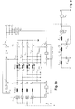
- Figure 1a and 1b
- together show the topology of a multiphase converter;
- Figure 2a and 2b
- together show measurement and control elements:
- Figure 3
- show a ground loop current equivalent circuit;
- Figure 4
- show two converters connected in parallel; and
- Figures 5-8
- trajectories of voltages and currents for different loads.
- In principle, identical parts are provided with the same reference symbols in the figures.
- The power circuit of a converter operating as an AC source considered in this work is shown in
Fig. 1 . The power converter is based on the three-level neutral point clamped (NPC) topology. At the input side, a three-phase voltage source rectifier provides controlled DC-link voltages and sinusoidal input currents. An input filter is included and it is assumed that the neutral point of the grid is connected to ground. The star point of the filter capacitors y is connected to the midpoint of the DC-link m through another capacitor Cmy, allowing the control of the midpoint potential with respect to ground. The output side has four legs with LC filters providing three controlled output voltages at the phase terminals A, B and C and at the neutral terminal N. The output voltages are defined with respect to the neutral terminal N and can be controlled independently. The control of the fourth leg is utilized in order to maximize the output voltage range of the three output phases or to be zero in case of loads connected to ground (assuming that the modulation of the input stage is without zero sequence voltage). The load can be balanced or unbalanced, linear or nonlinear, and with or without connection to ground. - A possible embodiment for the control scheme for the output stage is shown in
Fig. 2 . Each phase is controlled independently using a cascaded structure with an inner current control loop and an outer voltage control loop, optionally including feedforward loops of the load phase currents and reference voltages. The reference for the phase N can be calculated in order to maximize the voltage range of the other three output phases:
In case of ground connection of phase N, the reference voltage is set to zero, i.e. u*Nm =0. - As shown in
Fig. 2 , a PI controller regulates the ground current ignd with a reference value equal to zero. The output of this controller and a feed forward loop of the output neutral voltage uNm generate the reference voltage u* my . The second PI controller regulates the capacitor voltage umy and its output is the reference value for the zero sequence current controller. This third controller provides a fast control of the zero sequence current izs and generates the reference for the zero sequence voltage u0m. - In the input stage, a PI controller regulates the total DC-linc voltage uDC and generates the reference for the input phase current amplitude Î *, including a feed forward loop of the output current iout, which can be obtained from the output stage controller variables:

A moving average filter is used for the dc-link voltage uDC and load current iout in order to avoid distortions in the input currents due to periodic variations of the dc-link voltage generated by unbalanced operation of the output stage, e.g. with a single phase load. - For another explanation of the control scheme for the ground current, consider
Fig. 3 : The input side of the AC source is modeled in terms of the zero sequence components of the converter voltages and currents, and the common mode equivalent circuit of the input filter. The output stage (to the right of midpoint m) considers only the elements that affect the behavior of the ground current, i.e. the voltage at the neutral point N, with respect to the midpoint m of the DC-link, and the ground connection of the load. When a grounded load is connected at the output terminals, the neutral point output voltage uNm defines the potential of the midpoint m with respect to ground. For this reason the reference output voltage u* Nm is set to zero for operation with a grounded load. As it can be observed inFig. 2 , the ground current can be controlled by means of the voltage umy. The output voltage uNm can be considered to be a disturbance in the control loop. The reference for the voltage umy can be modified by the zero sequence current component izs. This idea corresponds to the cascaded control structure as shown inFig. 2 . - The control scheme provides the following advantages:
- a) Independent control of each output phase,
- b) Operation with any type of output voltage references (not limited to balanced three-phase voltages),
- c) Operation with any type of load (balanced/unbalanced, linear/nonlinear, floating/grounded),
- d) Prevention of ground circulating currents and inter-module circulating currents.
- A control loop for the voltage in the output terminal N is introduced for:
- e) Maximization of the output voltage range for floating loads,
- f) Prevention of ground circulating currents for grounded loads.
- The control of the zero sequence and circulating currents allows the safe operation of two or more AC sources.
- The input side control can be implemented using different reference frames for the currents and voltages:
- g) Control of the three-phases (abc),
- h) Orthogonal coordinates (αβ0),
- i) Rotating reference frame (dq0).
- The example in
Fig. 2 uses αβ0 coordinates for the current control. -
Fig. 4 shows a parallel connection of two converters or AC sources. When two or more AC sources are connected in parallel, the control scheme of each AC source remains the same at the input side, but a master-slave scheme can be implemented for the output stages. This means that only one AC source performs the control of the output voltages (master) and provides the current references for the other AC sources (slaves).Fig. 4 shows the output voltage and current references being passed from the master module M to the slave module S. -
Fig. 5-6 show simulated trajectories of voltages and currents for unbalanced loads and unbalanced voltages. The star point of the three-phase load is connected to N. In each figure, the trajectories are, from top to bottom, - the output voltages with reference to the neutral point (UAN, UBN, UCN)
- the output voltages with reference to the midpoint (UAm, UBm, UCm, UNm)
- the output currents (iA, iB, iC, iN)
-
Fig. 5 shows an unbalanced load. The unbalanced load presents a 200% higher resistance in phase C.Fig 6 shows a nonlinear load with unbalanced voltages (a diode bridge rectifier). Furthermore, each phase is controlled to work as an independent source: phase A with a 50Hz sinusoidal reference, phase B with a 100Hz sinusoidal reference and phase C as a DC source. -
Fig. 7-8 show the effect of ground current control: in both cases, the converter operates with balanced three-phase output voltages and unbalanced load. The unbalanced load presents a 200% higher resistance in phase C. In each figure, the trajectories are, from top to bottom, - input currents (ia, ib, ic)
- ground current (ignd )
- midpoint voltage (um,PE)
- While the invention has been described in present embodiments, it is distinctly understood that the invention is not limited thereto, but may be otherwise variously embodied and practised within the scope of the claims.
-
- [1] N. Kim, S.-Y. Kim, H.-G. Lee, C. Hwang, G.-H. Kim, H.-R. Seo, M. Park, and I.-K. Yu, "Design of a grid-simulator for a transient analysis of grid-connected renewable energy system," in International Conference on Electrical Machines and Systems (ICEMS), Oct.2010, pp. 633 - 637.
- [2] R. Lohde and F. Fuchs, "Laboratory type PWM grid emulator for generating disturbed voltages for testing grid connected devices," in 13th European Conference on Power Electronics and Applications (EPE '09), Sept. 2009, pp. 1 - 9.
- [3] O. Craciun, A. Florescu, S. Bacha, I. Munteanu, and A. Bratcu, "Hardware-in-the-loop testing of PV control systems using RT-Labsimulator," in 14th International Power Electronics and Motion Control Conference (EPE/PEMC), Sept. 2010, pp. S2-1 -S2-6.
- [4] R. Zhang, D. Boroyevich, V. Prasad, H.-C. Mao, F. Lee, and S. Dubovsky, "A three-phase inverter with a neutral leg with space vector modulation," in Proceedings of the 12th Applied Power Electronics Conference and Exposition (APEC'97), vol. 2, Feb. 1997,pp. 857 - 863.
- [5] S. El-Barbari and W. Hofmann, "Control of a 4 leg inverter for standalone photovoltaic systems," in Proceedings of the 4th IEEE International Conference on Power Electronics and Drive Systems, vol. 1, Oct. 2001, pp. 348 - 354.
- [6] M. Ryan, R. De Doncker, and R. Lorenz, "Decoupled control of a four-leg inverter via a new 4x4 transformation matrix," IEEE Transactions on Power Electronics, vol. 16, no. 5, pp. 694 - 701, Sept. 2001.
- [7] M. Ryan, "Analysis, modeling and control of three-phase, four-wire sine wave inverter systems," Ph.D. dissertation, University of Wisconsin - Madison, 1997.
- [8] J.-H. Kim and S.-K. Sul, "A carrier-based PWM method for three-phase four-leg voltage source converters," IEEE Transactions on Power Electronics, vol. 19, no. 1, pp. 66 -75, Jan. 2004.
- [9] J. Ai-juan, L. Hang-tian, and L. Shao-long, "A new matrix type three-phase four-wire power electronic transformer," in Proceedings of the 37th IEEE Power Electronics Specialists Conference (PESC '06), June 2006, pp. 1-6.
- [10]R. Zhang, V. Prasad, D. Boroyevich, and F. Lee, "Three-dimensional space vector modulation for four-leg voltage-source converters, "IEEE Transactions on Power Electronics, vol. 17, no. 3, pp. 314 - 326, May 2002.
- [11]R. Nasiri and A. Radan, "Pole-placement control strategy for 4-leg voltage-source inverters," in 1st Power Electronic Drive Systems Technologies Conference (PEDSTC), Feb. 2010, pp. 74 - 79.
- [12]Z. Ye, D. Boroyevich, J.-Y. Choi, and F. Lee, "Control of circulating current in two parallel three-phase boost rectifiers," IEEE Transactions on Power Electronics, vol. 17, no. 5, pp. 609 - 615, Sept. 2002.
- [13] C.-T. Pan and Y.-H. Liao, "Modeling and coordinate control of circulating currents in parallel three-phase boost rectifiers," IEEE Transactions on Industrial Electronics, vol. 54, no. 2, pp. 825 - 838, April 2007.
- [14] "Modeling and control of circulating currents for parallel three-phase boost rectifiers with different load sharing," IEEE Transactions on Industrial Electronics, vol. 55, no. 7, pp. 2776 - 2785, July 2008.
- [15]M. Baumann and J. Kolar, "Parallel connection of two three-phase three-switch buck-type unity-power-factor rectifier systems with dc-link current balancing," IEEE Transactions on Industrial Electronics, vol. 54, no. 6, pp. 3042 - 3053, Dec. 2007.
- [16] H. Shan, Y. Zhang, M. Yu, Y. Kang, Y. Liu, M. Yin, and H. Li, "The novel strategy of restraining circulating currents in distributed logical-control on parallel inverter system," in Proceedings of the International Conference on Electrical Machines and Systems (ICEMS 2009), Nov. 2009, pp. 1 - 5.
- [17] S. Ji, Y. Yong, and Q. Chunqing, "Control of circulating current for direct parallel grid-connected inverters in photovoltaic power generation," in Proceedings of the International Conference on Mechatronics and Automation (ICMA 2009), Aug. 2009, pp. 3805 -3810.
Claims (8)
- A method for controlling a multiphase AC power converter, wherein the power converter comprises• a multiphase primary stage for exchanging electrical energy between a multiphase voltage source and a DC link;• an input filter arranged between the primary stage and input terminals connecting the power converter to the multiphase voltage source;• a multiphase secondary stage for exchanging electrical energy between the DC link and phases of a multiphase load, this secondary stage comprising one bridge leg for each of the phases of the load and an additional bridge leg for a neutral point of the load;• the input filter comprising an input filter star point connected to a midpoint of the DC link via a connection capacitance (Cmy );wherein the method comprises the following steps for controlling a ground current (ignd ) flowing into the power converter:• an outer controller controlling the ground current (ignd ) to a reference value (i* gnd ) by generating a reference value (u * my ) for a voltage across the connection capacitance (Cmy );• an inner controller controlling the voltage (umy ) across the connection capacitance (Cmy ) to its reference value (u* my ) by generating a reference value (i* zs ) for a zero sequence current flowing through the connection capacitance (Cmy );• a zero sequence current controller controlling the zero sequence current (izs ) to its reference value (i * zs ).
- The method of claim 1, wherein the power converter comprises an output filter arranged between the secondary stage and output terminals that connect the power converter to the load, including the neutral point of the load, and wherein a star point of the output filter is connected to the midpoint of the DC link; the method comprising the step of• a feedforward circuit adding a potential (UNm ) of the secondary stage neutral point to the reference value generated by the outer controller before inputting it as a reference value (u* my ) to the inner controller.
- The method of claim 1 or claim 2, wherein the voltage source is a three phase system and the load comprises three phase connections and one neutral point connection to the secondary stage of the power converter.
- A multiphase AC power converter, wherein the power converter comprises• a multiphase primary stage for exchanging electrical energy between a multiphase voltage source and a DC link;• an input filter arranged between the primary stage and input terminals connecting the power converter to the multiphase voltage source;• a multiphase secondary stage for exchanging electrical energy between the DC link and phases of a multiphase load, this secondary stage comprising one bridge leg for each of the phases of the load and an additional bridge leg for a neutral point of the load;• the input filter comprising an input filter star point connected to a midpoint of the DC link via a connection capacitance (Cmy );• an output filter arranged between the secondary stage and output terminals that connect the power converter to the load, including the neutral point of the load, and• wherein a star point of the output filter is connected to the midpoint of the DC link.
- The multiphase AC power converter of claim 4, wherein the output filter, including filter elements for the neutral point, is a symmetric filter.
- The multiphase AC power converter of claim 4 or 5, comprising a controller for controlling ground loop currents, wherein the controller comprises the following units implemented in hard- and/or software for controlling a ground current (ignd ) flowing into the power converter:• an outer controller arranged to control the ground current (ignd ) to a reference value (i * gnd ) by generating a reference value (u* my ) for a voltage across the connection capacitance (Cmy );• an inner controller arranged to control the voltage (umy ) across the connection capacitance (Cmy ) to its reference value (u* my ) by generating a reference value (i* zs ) for a zero sequence current flowing into the connection capacitance (Cmy );• a zero sequence current controller arranged to control the zero sequence current (izs ) to its reference value (i* zs ).
- The multiphase AC power converter of claim 6, comprising a controller for the potential (UNm ) at the neutral point of the secondary stage that maximises the voltage range for the other three output phases.
- The multiphase AC power converter of claim 6 or 7, comprising a feedforward circuit arranged to add a potential (UNm ) of the neutral point of the secondary stage to the reference value generated by the outer controller before inputting it as a reference value (u* my) to the inner controller.
Applications Claiming Priority (1)
| Application Number | Priority Date | Filing Date | Title |
|---|---|---|---|
| CH11092013 | 2013-06-12 |
Publications (3)
| Publication Number | Publication Date |
|---|---|
| EP2814164A2 true EP2814164A2 (en) | 2014-12-17 |
| EP2814164A3 EP2814164A3 (en) | 2015-07-15 |
| EP2814164B1 EP2814164B1 (en) | 2017-08-16 |
Family
ID=50933015
Family Applications (1)
| Application Number | Title | Priority Date | Filing Date |
|---|---|---|---|
| EP14171958.3A Not-in-force EP2814164B1 (en) | 2013-06-12 | 2014-06-11 | A multiphase ac power converter and method for controlling a multiphase ac power converter |
Country Status (2)
| Country | Link |
|---|---|
| EP (1) | EP2814164B1 (en) |
| ES (1) | ES2642416T3 (en) |
Cited By (9)
| Publication number | Priority date | Publication date | Assignee | Title |
|---|---|---|---|---|
| WO2017125154A1 (en) * | 2016-01-21 | 2017-07-27 | Vacon Oy | Frequency converter with lcl line and common mode filter |
| CN107437800A (en) * | 2016-05-27 | 2017-12-05 | 比亚迪股份有限公司 | Vehicle-mounted filter, vehicle-mounted charging equipment and vehicle |
| CN110995115A (en) * | 2019-12-23 | 2020-04-10 | 深圳市凌康技术有限公司 | Improved three-dimensional space vector modulation method and system |
| KR102169390B1 (en) * | 2019-04-30 | 2020-10-23 | 아주대학교산학협력단 | Method and system for operating parallel inverter connected to grid |
| CN113381596A (en) * | 2020-03-09 | 2021-09-10 | 株洲中车奇宏散热技术有限公司 | Method for reducing overvoltage of wind power generator side filter |
| CN114696646A (en) * | 2022-04-20 | 2022-07-01 | 东北电力大学 | Multiphase voltage source converter topology and four-phase voltage source converter control method |
| LU501001B1 (en) * | 2021-12-13 | 2023-06-13 | ACD Antriebstechnik GmbH | Method for providing sinusoidal phase currents with control and charging |
| EP4382928A1 (en) * | 2022-12-09 | 2024-06-12 | ABB E-mobility B.V. | Method for detecting a stuck ac switch in a converter |
| DE102024105746A1 (en) | 2024-02-29 | 2025-09-04 | Bayerische Motoren Werke Aktiengesellschaft | DC link module for an inverter with a DC link capacitor unit and a suppression capacitor unit |
Family Cites Families (4)
| Publication number | Priority date | Publication date | Assignee | Title |
|---|---|---|---|---|
| JP4501144B2 (en) * | 2000-04-28 | 2010-07-14 | サンケン電気株式会社 | AC-DC converter |
| US6879053B1 (en) * | 2002-10-22 | 2005-04-12 | Youtility, Inc. | Transformerless, load adaptive speed controller |
| KR100875530B1 (en) * | 2008-03-19 | 2008-12-26 | 국제통신공업 주식회사 | Transformerless Power Inverter Using Chopper Technology |
| JP2010288381A (en) * | 2009-06-12 | 2010-12-24 | Fuji Electric Systems Co Ltd | Noise reduction circuit for power converter |
-
2014
- 2014-06-11 ES ES14171958.3T patent/ES2642416T3/en active Active
- 2014-06-11 EP EP14171958.3A patent/EP2814164B1/en not_active Not-in-force
Non-Patent Citations (17)
| Title |
|---|
| "Modeling and control of circulating currents for parallel three-phase boost rectifiers with different load sharing", IEEE TRANSACTIONS ON INDUSTRIAL ELECTRONICS, vol. 55, no. 7, July 2008 (2008-07-01), pages 2776 - 2785 |
| C.-T. PAN; Y.-H. LIAO: "Modeling and coordinate control of circulating currents in parallel three-phase boost rectifiers", IEEE TRANSACTIONS ON INDUSTRIAL ELECTRONICS, vol. 54, no. 2, April 2007 (2007-04-01), pages 825 - 838 |
| H. SHAN; Y. ZHANG; M. YU; Y. KANG; Y. LIU; M. YIN; H. LI: "The novel strategy of restraining circulating currents in distributed logical-control on parallel inverter system", PROCEEDINGS OF THE INTERNATIONAL CONFERENCE ON ELECTRICAL MACHINES AND SYSTEMS (ICEMS 2009, November 2009 (2009-11-01), pages 1 - 5 |
| J. AI-JUAN; L. HANG-TIAN; L. SHAO-LONG: "A new matrix type three-phase four-wire power electronic transformer", PROCEEDINGS OF THE 37TH IEEE POWER ELECTRONICS SPECIALISTS CONFERENCE (PESC '06, June 2006 (2006-06-01), pages 1 - 6 |
| J.-H. KIM; S.-K. SUL: "A carrier-based PWM method for three-phase four-leg voltage source converters", IEEE TRANSACTIONS ON POWER ELECTRONICS, vol. 19, no. 1, January 2004 (2004-01-01), pages 66 - 75 |
| M. BAUMANN; J. KOLAR: "Parallel connection of two three-phase three-switch buck-type unity-power-factor rectifier systems with dc-link current balancing", IEEE TRANSACTIONS ON INDUSTRIAL ELECTRONICS, vol. 54, no. 6, December 2007 (2007-12-01), pages 3042 - 3053 |
| M. R.YAN: "Analysis, modeling and control of three-phase, four-wire sine wave inverter systems", PH.D. DISSERTATION, UNIVERSITY OF WISCONSIN - MADISON, 1997 |
| M. RYAN; R. DE DONCKER; R. LORENZ: "Decoupled control of a four-leg inverter via a new 4x4 transformation matrix", IEEE TRANSACTIONS ON POWER ELECTRONICS, vol. 16, no. 5, September 2001 (2001-09-01), pages 694 - 701 |
| N. KIM; S.-Y. KIM; H.-G. LEE; C. HWANG; G.-H. KIM; H.-R. SEO; M. PARK; I.-K. YU: "Design of a grid-simulator for a transient analysis of grid-connected renewable energy system", INTERNATIONAL CONFERENCE ON ELECTRICAL MACHINES AND SYSTEMS (ICEMS, October 2010 (2010-10-01), pages 633 - 637 |
| O. CRACIUN; A. FLORESCU; S. BACHA; 1. MUNTEANU; A. BRATCU: "Hardware-in-the-loop testing of PV control systems using RT-Labsimulator", 14TH INTERNATIONAL POWER ELECTRONICS AND MOTION CONTROL CONFERENCE (EPE/PEMC, September 2010 (2010-09-01), pages S2 - 1,S --6 |
| R. LOHDE; F. FUCHS: "Laboratory type PWM grid emulator for generating disturbed voltages for testing grid connected devices", 13TH EUROPEAN CONFERENCE ON POWER ELECTRONICS AND APPLICATIONS (EPE '09, September 2009 (2009-09-01), pages 1 - 9 |
| R. NASIRI; A. RADAN: "Pole-placement control strategy for 4-leg voltage-source inverters", 1ST POWER ELECTRONIC DRIVE SYSTEMS TECHNOLOGIES CONFERENCE (PEDSTC, February 2010 (2010-02-01), pages 74 - 79 |
| R. ZHANG; D. BOROYEVICH; V. PRASAD; H.-C. MAO; F. LEE; S. DUBOVSKY: "A three-phase inverter with a neutral leg with space vector modulation", PROCEEDINGS OF THE 12TH APPLIED POWER ELECTRONICS CONFERENCE AND EXPOSITION (APEC'97, vol. 2, February 1997 (1997-02-01), pages 857 - 863 |
| R. ZHANG; V. PRASAD; D. BOROYEVICH; F. LEE: "Three-dimensional space vector modulation for four-leg voltage-source converters", IEEE TRANSACTIONS ON POWER ELECTRONICS, vol. 17, no. 3, May 2002 (2002-05-01), pages 314 - 326 |
| S. EL-BARBARI; W. HOFMANN: "Control of a 4 leg inverter for standalone photovoltaic systems", PROCEEDINGS OF THE 4TH IEEE INTERNATIONAL CONFERENCE ON POWER ELECTRONICS AND DRIVE SYSTEMS, vol. 1, October 2001 (2001-10-01), pages 348 - 354 |
| S. JI; Y. YONG; Q. CHUNQING: "Control of circulating current for direct parallel grid-connected inverters in photovoltaic power generation", PROCEEDINGS OF THE INTERNATIONAL CONFERENCE ON MECHATRONICS AND AUTOMATION (ICMA 2009, August 2009 (2009-08-01), pages 3805 - 3810 |
| Z. YE; D. BOROYEVICH; J.-Y. CHOI; F. LEE: "Control of circulating current in two parallel three-phase boost rectifiers", IEEE TRANSACTIONS ON POWER ELECTRONICS, vol. 17, no. 5, September 2002 (2002-09-01), pages 609 - 615 |
Cited By (13)
| Publication number | Priority date | Publication date | Assignee | Title |
|---|---|---|---|---|
| US10270367B2 (en) | 2016-01-21 | 2019-04-23 | Vacon Oy | Frequency converter with LCL line and common mode filter |
| WO2017125154A1 (en) * | 2016-01-21 | 2017-07-27 | Vacon Oy | Frequency converter with lcl line and common mode filter |
| CN107437800A (en) * | 2016-05-27 | 2017-12-05 | 比亚迪股份有限公司 | Vehicle-mounted filter, vehicle-mounted charging equipment and vehicle |
| CN107437800B (en) * | 2016-05-27 | 2020-07-10 | 比亚迪股份有限公司 | Vehicle-mounted filtering device, vehicle-mounted charging equipment and vehicle |
| KR102169390B1 (en) * | 2019-04-30 | 2020-10-23 | 아주대학교산학협력단 | Method and system for operating parallel inverter connected to grid |
| CN110995115B (en) * | 2019-12-23 | 2023-01-03 | 深圳市凌康技术有限公司 | Improved three-dimensional space vector modulation method and system |
| CN110995115A (en) * | 2019-12-23 | 2020-04-10 | 深圳市凌康技术有限公司 | Improved three-dimensional space vector modulation method and system |
| CN113381596A (en) * | 2020-03-09 | 2021-09-10 | 株洲中车奇宏散热技术有限公司 | Method for reducing overvoltage of wind power generator side filter |
| LU501001B1 (en) * | 2021-12-13 | 2023-06-13 | ACD Antriebstechnik GmbH | Method for providing sinusoidal phase currents with control and charging |
| WO2023110905A1 (en) | 2021-12-13 | 2023-06-22 | ACD Antriebstechnik GmbH | Method for providing sinusoidal phase currents, with actuation and charging |
| CN114696646A (en) * | 2022-04-20 | 2022-07-01 | 东北电力大学 | Multiphase voltage source converter topology and four-phase voltage source converter control method |
| EP4382928A1 (en) * | 2022-12-09 | 2024-06-12 | ABB E-mobility B.V. | Method for detecting a stuck ac switch in a converter |
| DE102024105746A1 (en) | 2024-02-29 | 2025-09-04 | Bayerische Motoren Werke Aktiengesellschaft | DC link module for an inverter with a DC link capacitor unit and a suppression capacitor unit |
Also Published As
| Publication number | Publication date |
|---|---|
| EP2814164A3 (en) | 2015-07-15 |
| EP2814164B1 (en) | 2017-08-16 |
| ES2642416T3 (en) | 2017-11-16 |
Similar Documents
| Publication | Publication Date | Title |
|---|---|---|
| EP2814164B1 (en) | A multiphase ac power converter and method for controlling a multiphase ac power converter | |
| Pouresmaeil et al. | A control technique for integration of DG units to the electrical networks | |
| Savaghebi et al. | Secondary control scheme for voltage unbalance compensation in an islanded droop-controlled microgrid | |
| Dasgupta et al. | Application of four-switch-based three-phase grid-connected inverter to connect renewable energy source to a generalized unbalanced microgrid system | |
| JP5721096B2 (en) | Power converter | |
| Bayhan et al. | Model predictive control of quasi-Z-source four-leg inverter | |
| Pouresmaeil et al. | Control scheme of three-level NPC inverter for integration of renewable energy resources into AC grid | |
| JP5455055B2 (en) | Power converter | |
| Kim et al. | Design and control of a grid-connected three-phase 3-level NPC inverter for building integrated photovoltaic systems | |
| Sun et al. | Topology and control of a split-capacitor four-wire current source inverter with leakage current suppression capability | |
| Jassim et al. | Modular current sharing control scheme for parallel-connected converters | |
| Abarzadeh et al. | A modified static ground power unit based on novel modular active neutral point clamped converter | |
| Li et al. | Distributed generation grid-connected converter testing device based on cascaded H-bridge topology | |
| Lazzarin et al. | DSP-based control for parallelism of three-phase voltage source inverter | |
| Bayhan et al. | Model predictive control of quasi-Z source three-phase four-leg inverter | |
| Ngo et al. | Grid-connected photovoltaic converters: Topology and grid interconnection | |
| Abarzadeh et al. | A modified static ground power unit based on active natural point clamped converter | |
| Hamasaki et al. | Control of hexagonal modular multilevel converter for 3-phase BTB system | |
| Bede et al. | Optimal interleaving angle determination in multi paralleled converters considering the DC current ripple and grid current THD | |
| Po-Ngam | The simplified control of three-phase four-leg shunt active power filter for harmonics mitigation, load balancing and reactive power compensation | |
| Yoo et al. | Control strategy of DC-link voltage for single-phase back-to-back cascaded H-bridge inverter for MV drive with interfacing transformer having tertiary winding | |
| Yang et al. | FPGA-based digital implementation of flexible power control for three-phase to single-phase MMC-based advanced co-phase traction power supply system | |
| Li et al. | A modulation scheme to reduce leakage current of split-capacitor four-wire current source inverter | |
| Shin et al. | 1.5 MVA grid-connected interleaved inverters using coupled inductors for wind power generation system | |
| Khoshkbar-Sadigh et al. | Analytical design of LC filter inductance for two-level inverters based on maximum ripple current |
Legal Events
| Date | Code | Title | Description |
|---|---|---|---|
| 17P | Request for examination filed |
Effective date: 20140611 |
|
| AK | Designated contracting states |
Kind code of ref document: A2 Designated state(s): AL AT BE BG CH CY CZ DE DK EE ES FI FR GB GR HR HU IE IS IT LI LT LU LV MC MK MT NL NO PL PT RO RS SE SI SK SM TR |
|
| AX | Request for extension of the european patent |
Extension state: BA ME |
|
| PUAI | Public reference made under article 153(3) epc to a published international application that has entered the european phase |
Free format text: ORIGINAL CODE: 0009012 |
|
| PUAL | Search report despatched |
Free format text: ORIGINAL CODE: 0009013 |
|
| AK | Designated contracting states |
Kind code of ref document: A3 Designated state(s): AL AT BE BG CH CY CZ DE DK EE ES FI FR GB GR HR HU IE IS IT LI LT LU LV MC MK MT NL NO PL PT RO RS SE SI SK SM TR |
|
| AX | Request for extension of the european patent |
Extension state: BA ME |
|
| RIC1 | Information provided on ipc code assigned before grant |
Ipc: H02M 7/23 20060101AFI20150610BHEP Ipc: H02M 1/12 20060101ALI20150610BHEP Ipc: H02M 5/458 20060101ALI20150610BHEP |
|
| RAP1 | Party data changed (applicant data changed or rights of an application transferred) |
Owner name: AIT AUSTRIAN INSTITUTE OF TECHNOLOGY GMBH |
|
| R17P | Request for examination filed (corrected) |
Effective date: 20151222 |
|
| RBV | Designated contracting states (corrected) |
Designated state(s): AL AT BE BG CH CY CZ DE DK EE ES FI FR GB GR HR HU IE IS IT LI LT LU LV MC MK MT NL NO PL PT RO RS SE SI SK SM TR |
|
| GRAP | Despatch of communication of intention to grant a patent |
Free format text: ORIGINAL CODE: EPIDOSNIGR1 |
|
| STAA | Information on the status of an ep patent application or granted ep patent |
Free format text: STATUS: GRANT OF PATENT IS INTENDED |
|
| INTG | Intention to grant announced |
Effective date: 20170302 |
|
| GRAS | Grant fee paid |
Free format text: ORIGINAL CODE: EPIDOSNIGR3 |
|
| GRAA | (expected) grant |
Free format text: ORIGINAL CODE: 0009210 |
|
| STAA | Information on the status of an ep patent application or granted ep patent |
Free format text: STATUS: THE PATENT HAS BEEN GRANTED |
|
| AK | Designated contracting states |
Kind code of ref document: B1 Designated state(s): AL AT BE BG CH CY CZ DE DK EE ES FI FR GB GR HR HU IE IS IT LI LT LU LV MC MK MT NL NO PL PT RO RS SE SI SK SM TR |
|
| REG | Reference to a national code |
Ref country code: GB Ref legal event code: FG4D |
|
| REG | Reference to a national code |
Ref country code: CH Ref legal event code: EP |
|
| REG | Reference to a national code |
Ref country code: IE Ref legal event code: FG4D |
|
| REG | Reference to a national code |
Ref country code: AT Ref legal event code: REF Ref document number: 919988 Country of ref document: AT Kind code of ref document: T Effective date: 20170915 |
|
| REG | Reference to a national code |
Ref country code: DE Ref legal event code: R096 Ref document number: 602014013109 Country of ref document: DE |
|
| REG | Reference to a national code |
Ref country code: CH Ref legal event code: NV Representative=s name: FREI PATENTANWALTSBUERO AG, CH |
|
| REG | Reference to a national code |
Ref country code: NL Ref legal event code: FP |
|
| REG | Reference to a national code |
Ref country code: ES Ref legal event code: FG2A Ref document number: 2642416 Country of ref document: ES Kind code of ref document: T3 Effective date: 20171116 |
|
| REG | Reference to a national code |
Ref country code: LT Ref legal event code: MG4D |
|
| PG25 | Lapsed in a contracting state [announced via postgrant information from national office to epo] |
Ref country code: FI Free format text: LAPSE BECAUSE OF FAILURE TO SUBMIT A TRANSLATION OF THE DESCRIPTION OR TO PAY THE FEE WITHIN THE PRESCRIBED TIME-LIMIT Effective date: 20170816 Ref country code: LT Free format text: LAPSE BECAUSE OF FAILURE TO SUBMIT A TRANSLATION OF THE DESCRIPTION OR TO PAY THE FEE WITHIN THE PRESCRIBED TIME-LIMIT Effective date: 20170816 Ref country code: SE Free format text: LAPSE BECAUSE OF FAILURE TO SUBMIT A TRANSLATION OF THE DESCRIPTION OR TO PAY THE FEE WITHIN THE PRESCRIBED TIME-LIMIT Effective date: 20170816 Ref country code: NO Free format text: LAPSE BECAUSE OF FAILURE TO SUBMIT A TRANSLATION OF THE DESCRIPTION OR TO PAY THE FEE WITHIN THE PRESCRIBED TIME-LIMIT Effective date: 20171116 |
|
| PG25 | Lapsed in a contracting state [announced via postgrant information from national office to epo] |
Ref country code: IS Free format text: LAPSE BECAUSE OF FAILURE TO SUBMIT A TRANSLATION OF THE DESCRIPTION OR TO PAY THE FEE WITHIN THE PRESCRIBED TIME-LIMIT Effective date: 20171216 Ref country code: BG Free format text: LAPSE BECAUSE OF FAILURE TO SUBMIT A TRANSLATION OF THE DESCRIPTION OR TO PAY THE FEE WITHIN THE PRESCRIBED TIME-LIMIT Effective date: 20171116 Ref country code: PL Free format text: LAPSE BECAUSE OF FAILURE TO SUBMIT A TRANSLATION OF THE DESCRIPTION OR TO PAY THE FEE WITHIN THE PRESCRIBED TIME-LIMIT Effective date: 20170816 Ref country code: RS Free format text: LAPSE BECAUSE OF FAILURE TO SUBMIT A TRANSLATION OF THE DESCRIPTION OR TO PAY THE FEE WITHIN THE PRESCRIBED TIME-LIMIT Effective date: 20170816 Ref country code: LV Free format text: LAPSE BECAUSE OF FAILURE TO SUBMIT A TRANSLATION OF THE DESCRIPTION OR TO PAY THE FEE WITHIN THE PRESCRIBED TIME-LIMIT Effective date: 20170816 Ref country code: GR Free format text: LAPSE BECAUSE OF FAILURE TO SUBMIT A TRANSLATION OF THE DESCRIPTION OR TO PAY THE FEE WITHIN THE PRESCRIBED TIME-LIMIT Effective date: 20171117 |
|
| PG25 | Lapsed in a contracting state [announced via postgrant information from national office to epo] |
Ref country code: DK Free format text: LAPSE BECAUSE OF FAILURE TO SUBMIT A TRANSLATION OF THE DESCRIPTION OR TO PAY THE FEE WITHIN THE PRESCRIBED TIME-LIMIT Effective date: 20170816 Ref country code: RO Free format text: LAPSE BECAUSE OF FAILURE TO SUBMIT A TRANSLATION OF THE DESCRIPTION OR TO PAY THE FEE WITHIN THE PRESCRIBED TIME-LIMIT Effective date: 20170816 Ref country code: CZ Free format text: LAPSE BECAUSE OF FAILURE TO SUBMIT A TRANSLATION OF THE DESCRIPTION OR TO PAY THE FEE WITHIN THE PRESCRIBED TIME-LIMIT Effective date: 20170816 |
|
| REG | Reference to a national code |
Ref country code: DE Ref legal event code: R097 Ref document number: 602014013109 Country of ref document: DE |
|
| PG25 | Lapsed in a contracting state [announced via postgrant information from national office to epo] |
Ref country code: SM Free format text: LAPSE BECAUSE OF FAILURE TO SUBMIT A TRANSLATION OF THE DESCRIPTION OR TO PAY THE FEE WITHIN THE PRESCRIBED TIME-LIMIT Effective date: 20170816 Ref country code: IT Free format text: LAPSE BECAUSE OF FAILURE TO SUBMIT A TRANSLATION OF THE DESCRIPTION OR TO PAY THE FEE WITHIN THE PRESCRIBED TIME-LIMIT Effective date: 20170816 Ref country code: EE Free format text: LAPSE BECAUSE OF FAILURE TO SUBMIT A TRANSLATION OF THE DESCRIPTION OR TO PAY THE FEE WITHIN THE PRESCRIBED TIME-LIMIT Effective date: 20170816 Ref country code: SK Free format text: LAPSE BECAUSE OF FAILURE TO SUBMIT A TRANSLATION OF THE DESCRIPTION OR TO PAY THE FEE WITHIN THE PRESCRIBED TIME-LIMIT Effective date: 20170816 |
|
| REG | Reference to a national code |
Ref country code: FR Ref legal event code: PLFP Year of fee payment: 5 |
|
| PLBE | No opposition filed within time limit |
Free format text: ORIGINAL CODE: 0009261 |
|
| STAA | Information on the status of an ep patent application or granted ep patent |
Free format text: STATUS: NO OPPOSITION FILED WITHIN TIME LIMIT |
|
| 26N | No opposition filed |
Effective date: 20180517 |
|
| PG25 | Lapsed in a contracting state [announced via postgrant information from national office to epo] |
Ref country code: SI Free format text: LAPSE BECAUSE OF FAILURE TO SUBMIT A TRANSLATION OF THE DESCRIPTION OR TO PAY THE FEE WITHIN THE PRESCRIBED TIME-LIMIT Effective date: 20170816 |
|
| REG | Reference to a national code |
Ref country code: CH Ref legal event code: PCAR Free format text: NEW ADDRESS: POSTFACH, 8032 ZUERICH (CH) |
|
| PG25 | Lapsed in a contracting state [announced via postgrant information from national office to epo] |
Ref country code: LU Free format text: LAPSE BECAUSE OF NON-PAYMENT OF DUE FEES Effective date: 20180611 Ref country code: MC Free format text: LAPSE BECAUSE OF FAILURE TO SUBMIT A TRANSLATION OF THE DESCRIPTION OR TO PAY THE FEE WITHIN THE PRESCRIBED TIME-LIMIT Effective date: 20170816 |
|
| PGFP | Annual fee paid to national office [announced via postgrant information from national office to epo] |
Ref country code: FR Payment date: 20190619 Year of fee payment: 6 |
|
| PG25 | Lapsed in a contracting state [announced via postgrant information from national office to epo] |
Ref country code: MT Free format text: LAPSE BECAUSE OF NON-PAYMENT OF DUE FEES Effective date: 20180611 |
|
| PG25 | Lapsed in a contracting state [announced via postgrant information from national office to epo] |
Ref country code: TR Free format text: LAPSE BECAUSE OF FAILURE TO SUBMIT A TRANSLATION OF THE DESCRIPTION OR TO PAY THE FEE WITHIN THE PRESCRIBED TIME-LIMIT Effective date: 20170816 |
|
| PG25 | Lapsed in a contracting state [announced via postgrant information from national office to epo] |
Ref country code: PT Free format text: LAPSE BECAUSE OF FAILURE TO SUBMIT A TRANSLATION OF THE DESCRIPTION OR TO PAY THE FEE WITHIN THE PRESCRIBED TIME-LIMIT Effective date: 20170816 Ref country code: HU Free format text: LAPSE BECAUSE OF FAILURE TO SUBMIT A TRANSLATION OF THE DESCRIPTION OR TO PAY THE FEE WITHIN THE PRESCRIBED TIME-LIMIT; INVALID AB INITIO Effective date: 20140611 |
|
| PG25 | Lapsed in a contracting state [announced via postgrant information from national office to epo] |
Ref country code: HR Free format text: LAPSE BECAUSE OF FAILURE TO SUBMIT A TRANSLATION OF THE DESCRIPTION OR TO PAY THE FEE WITHIN THE PRESCRIBED TIME-LIMIT Effective date: 20170816 Ref country code: CY Free format text: LAPSE BECAUSE OF FAILURE TO SUBMIT A TRANSLATION OF THE DESCRIPTION OR TO PAY THE FEE WITHIN THE PRESCRIBED TIME-LIMIT Effective date: 20170816 Ref country code: MK Free format text: LAPSE BECAUSE OF NON-PAYMENT OF DUE FEES Effective date: 20170816 |
|
| PG25 | Lapsed in a contracting state [announced via postgrant information from national office to epo] |
Ref country code: AL Free format text: LAPSE BECAUSE OF FAILURE TO SUBMIT A TRANSLATION OF THE DESCRIPTION OR TO PAY THE FEE WITHIN THE PRESCRIBED TIME-LIMIT Effective date: 20170816 |
|
| PGFP | Annual fee paid to national office [announced via postgrant information from national office to epo] |
Ref country code: DE Payment date: 20200618 Year of fee payment: 7 Ref country code: CH Payment date: 20200611 Year of fee payment: 7 Ref country code: IE Payment date: 20200624 Year of fee payment: 7 |
|
| PGFP | Annual fee paid to national office [announced via postgrant information from national office to epo] |
Ref country code: NL Payment date: 20200625 Year of fee payment: 7 Ref country code: GB Payment date: 20200625 Year of fee payment: 7 Ref country code: BE Payment date: 20200625 Year of fee payment: 7 |
|
| PGFP | Annual fee paid to national office [announced via postgrant information from national office to epo] |
Ref country code: AT Payment date: 20200619 Year of fee payment: 7 |
|
| PGFP | Annual fee paid to national office [announced via postgrant information from national office to epo] |
Ref country code: ES Payment date: 20200825 Year of fee payment: 7 |
|
| REG | Reference to a national code |
Ref country code: AT Ref legal event code: UEP Ref document number: 919988 Country of ref document: AT Kind code of ref document: T Effective date: 20170816 |
|
| PG25 | Lapsed in a contracting state [announced via postgrant information from national office to epo] |
Ref country code: FR Free format text: LAPSE BECAUSE OF NON-PAYMENT OF DUE FEES Effective date: 20200630 |
|
| REG | Reference to a national code |
Ref country code: DE Ref legal event code: R119 Ref document number: 602014013109 Country of ref document: DE |
|
| REG | Reference to a national code |
Ref country code: CH Ref legal event code: PL |
|
| REG | Reference to a national code |
Ref country code: NL Ref legal event code: MM Effective date: 20210701 |
|
| REG | Reference to a national code |
Ref country code: AT Ref legal event code: MM01 Ref document number: 919988 Country of ref document: AT Kind code of ref document: T Effective date: 20210611 |
|
| GBPC | Gb: european patent ceased through non-payment of renewal fee |
Effective date: 20210611 |
|
| REG | Reference to a national code |
Ref country code: BE Ref legal event code: MM Effective date: 20210630 |
|
| PG25 | Lapsed in a contracting state [announced via postgrant information from national office to epo] |
Ref country code: LI Free format text: LAPSE BECAUSE OF NON-PAYMENT OF DUE FEES Effective date: 20210630 Ref country code: IE Free format text: LAPSE BECAUSE OF NON-PAYMENT OF DUE FEES Effective date: 20210611 Ref country code: GB Free format text: LAPSE BECAUSE OF NON-PAYMENT OF DUE FEES Effective date: 20210611 Ref country code: DE Free format text: LAPSE BECAUSE OF NON-PAYMENT OF DUE FEES Effective date: 20220101 Ref country code: CH Free format text: LAPSE BECAUSE OF NON-PAYMENT OF DUE FEES Effective date: 20210630 Ref country code: AT Free format text: LAPSE BECAUSE OF NON-PAYMENT OF DUE FEES Effective date: 20210611 |
|
| PG25 | Lapsed in a contracting state [announced via postgrant information from national office to epo] |
Ref country code: NL Free format text: LAPSE BECAUSE OF NON-PAYMENT OF DUE FEES Effective date: 20210701 |
|
| PG25 | Lapsed in a contracting state [announced via postgrant information from national office to epo] |
Ref country code: BE Free format text: LAPSE BECAUSE OF NON-PAYMENT OF DUE FEES Effective date: 20210630 |
|
| REG | Reference to a national code |
Ref country code: ES Ref legal event code: FD2A Effective date: 20220826 |
|
| PG25 | Lapsed in a contracting state [announced via postgrant information from national office to epo] |
Ref country code: ES Free format text: LAPSE BECAUSE OF NON-PAYMENT OF DUE FEES Effective date: 20210612 |