EP2814129A1 - Method and means for complex, universal earth fault protection in power high and medium voltage system - Google Patents
Method and means for complex, universal earth fault protection in power high and medium voltage system Download PDFInfo
- Publication number
- EP2814129A1 EP2814129A1 EP13002965.5A EP13002965A EP2814129A1 EP 2814129 A1 EP2814129 A1 EP 2814129A1 EP 13002965 A EP13002965 A EP 13002965A EP 2814129 A1 EP2814129 A1 EP 2814129A1
- Authority
- EP
- European Patent Office
- Prior art keywords
- current
- protection
- residual current
- earth fault
- fault protection
- Prior art date
- Legal status (The legal status is an assumption and is not a legal conclusion. Google has not performed a legal analysis and makes no representation as to the accuracy of the status listed.)
- Granted
Links
Images





Classifications
-
- H—ELECTRICITY
- H02—GENERATION; CONVERSION OR DISTRIBUTION OF ELECTRIC POWER
- H02H—EMERGENCY PROTECTIVE CIRCUIT ARRANGEMENTS
- H02H7/00—Emergency protective circuit arrangements specially adapted for specific types of electric machines or apparatus or for sectionalised protection of cable or line systems, and effecting automatic switching in the event of an undesired change from normal working conditions
- H02H7/22—Emergency protective circuit arrangements specially adapted for specific types of electric machines or apparatus or for sectionalised protection of cable or line systems, and effecting automatic switching in the event of an undesired change from normal working conditions for distribution gear, e.g. bus-bar systems; for switching devices
- H02H7/222—Emergency protective circuit arrangements specially adapted for specific types of electric machines or apparatus or for sectionalised protection of cable or line systems, and effecting automatic switching in the event of an undesired change from normal working conditions for distribution gear, e.g. bus-bar systems; for switching devices for switches
-
- H—ELECTRICITY
- H02—GENERATION; CONVERSION OR DISTRIBUTION OF ELECTRIC POWER
- H02H—EMERGENCY PROTECTIVE CIRCUIT ARRANGEMENTS
- H02H3/00—Emergency protective circuit arrangements for automatic disconnection directly responsive to an undesired change from normal electric working condition with or without subsequent reconnection ; integrated protection
- H02H3/16—Emergency protective circuit arrangements for automatic disconnection directly responsive to an undesired change from normal electric working condition with or without subsequent reconnection ; integrated protection responsive to fault current to earth, frame or mass
- H02H3/162—Emergency protective circuit arrangements for automatic disconnection directly responsive to an undesired change from normal electric working condition with or without subsequent reconnection ; integrated protection responsive to fault current to earth, frame or mass for AC systems
- H02H3/165—Emergency protective circuit arrangements for automatic disconnection directly responsive to an undesired change from normal electric working condition with or without subsequent reconnection ; integrated protection responsive to fault current to earth, frame or mass for AC systems for three-phase systems
Definitions
- the Invention relates to a method and means for earth fault in power high and/or medium voltage system, according to the preamble of claim 1 and 8.
- Residual current detection is a key in earth-fault protection systems of power systems.
- CBCT core balance current transformer
- the output of the transformer is is adequate to the residual current of the system below the CBCT in the direction of power flow. That part of the system, which is above the CBCT is not protected by use of that CBCT.
- This first method can be used in electrical network systems with low earth current, e.g. the compensated network. For use in the electrical network system with large earth current this method is expensive.
- the second method of residual current detection uses the phase-current information from the instrument transformers. This information is then summed and the result is the residual current.
- This method can be used in electrical network systems with large earth current, e.g. resistor earthed network. It cannot be used in electrical network system with low earth current due to the sensitivity of current transformers.
- the solution given by the invention is, that for earth fault protection in electrical power system and/or the electrical power system part, for example, but not limited to, protection of the cable connectors, whiches residual current is determined indirectly by the calculation from the phase current values, obtained from the output signals of
- An advantageous embodiment of the invention ist, that the Rogowski coil based sensors transform the phase currents to voltage signals and the voltage outputs of the sensors is connected to a protection relay (IED) which digitalizes the voltage values which are then conditioned and then transformed to the value of the measured current, together with the actual phase of it.
- IED protection relay
- a further advantageous step is that the residual current is then determined in the protection relay (IED) as vector sum of the phase current.
- the value of the residual current is then compared to a preset level, and preset measures are taken to setting the alarm and/or switching off the circuit breaker and/or sending the information to the superior system level.
- the residual current value can be displayed on a display of the protection relay (IED), to the operator, or send to a superior control system using digital network.
- IED protection relay
- the sensitive detection of residual current is essential for EF protection, particularly in systems with a low level of earth fault currents.
- a core balanced (ring type) current transformer CBCT
- CBCT core balanced current transformer
- the CBCT represents additional equipment which requires the engineering of its parameters as well as materials and other cost investments.
- CTs current transformers
- a typical example is the current sensor which can measure accurately phase currents from a few amps (A) up to tens of kilo-amps (kA). This means that the apparent residual current created by measurement inaccuracy can be very low and therefore there might not be limitation in using the calculated residual current from sensor phase current measurements in any system, even with extremely low levels of earth fault current.
- one standard sensor can be used for a broad range of rated currents and is also capable of precisely transferring signals containing wide range of frequencies different from rated ones.
- the typical example of a current sensor can reach the metering class 0.5 for continuous current measurement in the extended accuracy range from 5% of the rated primary current (e.g. 4 A) up to the rated continuous thermal current (e.g. 4000 A).
- current sensors can fulfill the requirements of the protection class up to an impressive value reaching the rated short-time thermal current (e.g. 50 kA).
- the zero phase current is calculated as vector sum of phase currents. Phase currents are determined from the digitalized values of the Rogowski coil sensor singals.
- the method is used for generation of switch-off and/or earthing and/or short cutting, by sensitive earth fault protection in power systems.
- the current sensor can be placed at each desired or important region of the power system, for example, but not limited to, inside the switchgear containment, because of its very compact measures.
- Rogowski coils have the advantage in that use, that in absence of iron cores the saturation phenomena is eliminated and therefore dynamic measurement range grows substantially. Since Rogowski coil has linear characteristic, the very accurate measurement is provided in the whole operating range. Then it is possible, to measure reliably and accurate currents much smaller as well as much higher, then it could be possible by conventional current transformes with the same nominal current rating.
- a panel with Rogowski coil based sensors, signal of whose is used for residual current calculation provides significant competitive advantage among other solutions. Residual current can be calculated precisely in wider range than with conventional transformers. High precision sensors can provide information accurate enough to be used in both low and large earth current electrical network systems.
- a calculation algorithm for determination of the sensor signal value is implemented as an exchangeable software-program-product, whiches parameters are adjusted or adjustable to the specific use in the switchgear of other applications, in that way, that the calculation algorithm is transferable into the steering electronic via a data medium, or a data file send via browser.
- Earth fault protection system for switchgears itself, consist of at least one coreless Rogowski coil used for each of a three-phase current path, and that the rogowski coils are combined with protection relays in that way, that residual current of the feeders of the switchgear can be calculated, and in case of a residual current over the preset limit is detected, the earth fault protection is activated.
- the rogowski coil is applied in a thin ringshaped sensor housing, and that the sensor housing has concentric outer ribs, in order to enlarge creepage path along the diameter of the sensor housing ring.
- the advantage of the invention is, that the sensor is small enough to fit in the tight space in the circuit breaker compartment and it has such nominal ratio (80A/150mV), that it can measure the phase currents with accuracy good enough for sufficient I0 calculation.
- the invention ist, that at least one coreless Rogowski coil is used for each of a three-phase current path, and that the rogowski coils are combined with protection relays in that way, that residual current of the feeders of the switchgear can be calculated, and in case of a residual current value reaches preset level, the earth fault protection is activated.
- the rogowski coil is applied in a thin ringshaped sensor housing, and that the sensor housing has concentric outer ribs, in order to enlarge creepage path along the diameter of the sensor housing ring.
- the best placement for the coils is, that the rogowski coil or the rogowski coils are arranged between the ribs.
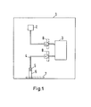
- Figure 1 shows an overview of a medium voltage switchgear panel 1. Inside is shown the busbar 2 and the circuit breaker 3, with higher and lower connection point or terminal. The sensors 8 are located and placed between the cable connector 4 and the connectors of the Circuit breaker 3. So because of the fact, that the rogowski coil sensors are small enough, they can be easily arranged there.
- Modern microprocessor-based protection relays enable calculation of residual current as a vector sum of three phase currents.
- conventional CTs are used for phase current measurements. Due to the measurement error of each CT, it is recommended to use calculated residual current like shown in figures 2 and 3 , only if the earth fault current is higher than 10% of nominal current. In other cases it is recommended to use CBCT.
- the recommendation assumes that CTs with protection accuracy class have been used and therefore limited accuracy of such class is considered with additional safety margin.
- the amplitude and phase errors of the CTs distort measured phase currents.
- the Intelligent Electronic Device (IED) then sees the different phase currents than real phase currents in the network. Consequently apparent residual current is created due to measurement inaccuracy.
- the level of apparent residual current is usually quite difficult to determine; moreover, this component could affect the correct function of the EF protection. If the apparent residual current is too high in relation to the earth fault current, it could cause malfunction of EF protection (false operation or failure to operation). 10 - real earth fault current in the network I0(ap) - apparent residual current I0(r) - earth fault current seen by IED On the other hand, if the measurement is very accurate in the whole operating range provided by the sensors, the apparent residual current could then be very low without significant impact on operation of EF protection.
- the primary tests of EF protection based on calculated residual current in steady-state conditions were done to determine the level of the apparent residual current.
- the tests were done in a laboratory with the primary current source which supplied the 3-phase current in the range 0-2000 A to the three connected sensors.
- the testing system was connected as an isolated network (without any connection of neutral to the ground), therefore no real residual current could appear. Consequently the trip of earth fault protection could cause only apparent residual current created by measurement inaccuracy.
- the level of apparent residual current was detected by a gradual increase of injected primary current (Ip) and by adjusting of EF protection start current. If the EF protection tripped, the apparent residual current was higher than EF protection start current I0(op).
- the primary current (Ip) was injected in the step 10 A in the range 20 - 1000 A and then in the step 25 A in the range 1000 - 2000 A.
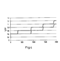
- the upper curve (Inoperative) on Figure 4 represents the characteristic when EF protection did not trip and the lower curve (Operative) represents the characteristic when EF protection was activated by apparent residual current and tripped. Consequently the amplitude of apparent residual current then reached the values between the blue and the red characteristics expressed by the grey zone. From the results it is evident that apparent residual current reached very acceptable values which proved the high accuracy of sensor measurement e.g. for injected current 2000 A was apparent residual current in the range 1-1.2 A. The results of the test signified very promising precondition to decrease recommended setting of EF protection from 10% of nominal current to lower values if the calculated residual current from sensor measurement is used.
- the primary tests of EF protection based on calculated residual current on the model of the network were done to prove the behaviour in transient conditions and to verify the positive results from the previous test done in a laboratory in steady-state conditions.
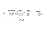
- the model of the network consisted of a supply step-up transformer, circuit breaker, transformer which enabled to create required type of network neutral grounding, and different types of burdens e.g. power transformer for stability test on inrush current or capacitors for earth fault tests.
- FIG. 5 displays a simplified scheme of network model stability test on inrush current.
- Inrush current represents a problematic element for conventional CTs in case that CTs cannot be designed with appropriate parameters (mainly due to limited size or required low-rated primary current).
- the IED REF615 was connected to the combined sensors for phase current and phase voltage measurements.
- CBCT connected to the REF615 was used as a reference.
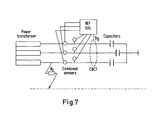
- Figure 6 displays simplified scheme of connected equipment during the stability test.
- the EF protection in REF615
- the EF protection was set on the most sensitive (minimum) settings:
- phase L1 was connected to the ground. In total, six tests were done where correct detection of earth fault currents as well as proper directional function (forward and reverse) were verified.
- the phase currents before the earth fault were approximately 0.5 A.
- the earth fault current was approximately 1.6 A during the tests and EF protection always detected this earth fault current correctly.
- Maximum amplitude deviation between calculated residual current (from 3-phase current sensor measurement) and directly measured residual current (by CBCT) was about 0.1 A. The deviation could be caused by apparent residual current on the side of calculated residual current but on the other side also accuracy of the reference CBCT could be limited due to measurement of such low currents.
- impedance earth faults in isolated network Considering impedance earth faults in isolated network;
- Rf 1.13 ⁇ ; 50 ⁇ ; 100 ⁇ ; 114 ⁇ ; 115 ⁇ .
- the earth fault currents were in the range from 1.6 A up to 0.7 A.
- Maximum amplitude deviation between calculated residual current (from 3-phase current sensor) and directly measured residual current (by CBCT) was again about 0.1 A.
- Figure 8 shows a housing, in which the rogowski coil is arranged.
- the housing has two flange elements at the edges a fixation points.
- the housing has a round inner opening for the conductor.
- the peripherie applied with concentric structures, in order to enlarge the creepage path parallel to the diameters direction.
- the cut along the diameter of the housing makes the enlargement of the creepage lenght visible.
- the inner surface of the housing is metalized to form grounded shielding, and the components forming the Rogowski coil are cast in that housing.
Landscapes
- Engineering & Computer Science (AREA)
- Power Engineering (AREA)
- Measuring Instrument Details And Bridges, And Automatic Balancing Devices (AREA)
- Emergency Protection Circuit Devices (AREA)
Abstract
Description
- The Invention relates to a method and means for earth fault in power high and/or medium voltage system, according to the preamble of
claim - Residual current detection is a key in earth-fault protection systems of power systems. There are two methods to detect the residual current. In the first method, core balance current transformer (CBCT) is used. The output of the transformer is is adequate to the residual current of the system below the CBCT in the direction of power flow. That part of the system, which is above the CBCT is not protected by use of that CBCT. This first method can be used in electrical network systems with low earth current, e.g. the compensated network. For use in the electrical network system with large earth current this method is expensive.
The second method of residual current detection uses the phase-current information from the instrument transformers. This information is then summed and the result is the residual current. This method can be used in electrical network systems with large earth current, e.g. resistor earthed network. It cannot be used in electrical network system with low earth current due to the sensitivity of current transformers. - So it is the object of the invention, to develop a protection system for special technical task, which is to measure residual current.
- The solution, given by the invention is, that for earth fault protection in electrical power system and/or the electrical power system part, for example, but not limited to, protection of the cable connectors, whiches residual current is determined indirectly by the calculation from the phase current values, obtained from the output signals of
- Rogowski-coil based current sensors.
- An advantageous embodiment of the invention ist, that the Rogowski coil based sensors transform the phase currents to voltage signals and the voltage outputs of the sensors is connected to a protection relay (IED) which digitalizes the voltage values which are then conditioned and then transformed to the value of the measured current, together with the actual phase of it.
- A further advantageous step is that the residual current is then determined in the protection relay (IED) as vector sum of the phase current.
- The value of the residual current is then compared to a preset level, and preset measures are taken to setting the alarm and/or switching off the circuit breaker and/or sending the information to the superior system level.
- Optionally the residual current value can be displayed on a display of the protection relay (IED), to the operator, or send to a superior control system using digital network.
- The sensitive detection of residual current is essential for EF protection, particularly in systems with a low level of earth fault currents. There are many methods for the detection of residual current. In compensated or small isolated systems, a core balanced (ring type) current transformer (CBCT) is typically used. Even though EF protection with a CBCT is widely used, the CBCT represents additional equipment which requires the engineering of its parameters as well as materials and other cost investments.
With the development of digital protection relays, residual current can be easily calculated as a vector sum of three phase currents. However, with traditional current transformers (CTs) this method has a significant drawback due to the limited accuracy caused by the limited size of the CTs. The inaccuracy of this measurement creates an apparent residual current which affects the EF protection function. Therefore, it is recommended to use the residual current calculated from phase CTs only in systems with high levels of earth fault currents. - Sensors, with their linear characteristics and no saturation, provide highly accurate measurements across the whole operating range. A typical example is the current sensor which can measure accurately phase currents from a few amps (A) up to tens of kilo-amps (kA). This means that the apparent residual current created by measurement inaccuracy can be very low and therefore there might not be limitation in using the calculated residual current from sensor phase current measurements in any system, even with extremely low levels of earth fault current.
- Due to the absence of a ferromagnetic core the sensor has a linear response over a very wide primary current range, far exceeding the typical current transformer range. Thus, current sensing for both measurement and protection purposes could be realized with single secondary winding. In addition, one standard sensor can be used for a broad range of rated currents and is also capable of precisely transferring signals containing wide range of frequencies different from rated ones.
The typical example of a current sensor can reach the metering class 0.5 for continuous current measurement in the extended accuracy range from 5% of the rated primary current (e.g. 4 A) up to the rated continuous thermal current (e.g. 4000 A). For dynamic current measurement (for protection purposes), current sensors can fulfill the requirements of the protection class up to an impressive value reaching the rated short-time thermal current (e.g. 50 kA). - The zero phase current is calculated as vector sum of phase currents. Phase currents are determined from the digitalized values of the Rogowski coil sensor singals.
- In a further advantageous embodiment, the method is used for generation of switch-off and/or earthing and/or short cutting, by sensitive earth fault protection in power systems.
By the use of Rogowski coils, the current sensor can be placed at each desired or important region of the power system, for example, but not limited to, inside the switchgear containment, because of its very compact measures. Furthermore Rogowski coils have the advantage in that use, that in absence of iron cores the saturation phenomena is eliminated and therefore dynamic measurement range grows substantially. Since Rogowski coil has linear characteristic, the very accurate measurement is provided in the whole operating range. Then it is possible, to measure reliably and accurate currents much smaller as well as much higher, then it could be possible by conventional current transformes with the same nominal current rating. - A panel with Rogowski coil based sensors, signal of whose is used for residual current calculation provides significant competitive advantage among other solutions. Residual current can be calculated precisely in wider range than with conventional transformers. High precision sensors can provide information accurate enough to be used in both low and large earth current electrical network systems.
- In a further advantageous embodiment of the invention, a calculation algorithm for determination of the sensor signal value is implemented as an exchangeable software-program-product, whiches parameters are adjusted or adjustable to the specific use in the switchgear of other applications, in that way, that the calculation algorithm is transferable into the steering electronic via a data medium, or a data file send via browser.
This is significantly advantageous, because it concludes the small and compact dimensions of the inventive current sensor use, with an easy retrofit of each switchgear. So the current sensors can be retrofit, and in the same time the algorithm for their steering and implementation in the protection system can be easily be retrofit in then same way, by only easy implementation by transfer of algorithm data via data media or data file into the steering system of switchgear. - Earth fault protection system for switchgears itself, consist of at least one coreless Rogowski coil used for each of a three-phase current path, and that the rogowski coils are combined with protection relays in that way, that residual current of the feeders of the switchgear can be calculated, and in case of a residual current over the preset limit is detected, the earth fault protection is activated.
- In a further advantageous embodiment of the invention, the rogowski coil is applied in a thin ringshaped sensor housing, and that the sensor housing has concentric outer ribs, in order to enlarge creepage path along the diameter of the sensor housing ring.
- The advantage of the invention is, that the sensor is small enough to fit in the tight space in the circuit breaker compartment and it has such nominal ratio (80A/150mV), that it can measure the phase currents with accuracy good enough for sufficient I0 calculation.
- Basic idea for this solution is, to use such sensors, in order
to the lack of saturation phenomenon, with a very broad measuring range; in this case it can measure from 4A to 4000A. Protection of cable ends and connector is important as this is part of switchgear, which is prepared manually during the installation and as result of human error, damage to isolation and/or shield layers, or material impurity, failures occur relatively often there. - According to an earth fault protection system of the cable connectors in high and/or medium voltage switchgears, wherein Rogowski coils are used for current sensing, the invention ist, that at least one coreless Rogowski coil is used for each of a three-phase current path, and that the rogowski coils are combined with protection relays in that way, that residual current of the feeders of the switchgear can be calculated, and in case of a residual current value reaches preset level, the earth fault protection is activated.
- In a further very advantageous embodiment, the rogowski coil is applied in a thin ringshaped sensor housing, and that the sensor housing has concentric outer ribs, in order to enlarge creepage path along the diameter of the sensor housing ring.
- The best placement for the coils is, that the rogowski coil or the rogowski coils are arranged between the ribs.
- Advantageous embodiments are shown in the figures:
-
Figure 1 : Overview of the use of the sensor in a medium voltage switchgear. -
Figure 2 : creation of apparent residual current -
Figure 3 : Impact of apparent residual current on EF protection performance -
Figure 4 : Relation between apparent residual current and injected primary current -
Figure 5 : Simplified scheme of network model -
Figure 6 : Simplified scheme of connected equipement -
Figure 7 : Simplified scheme of connected equipement -
Figure 8 : detail sensor housing in front view -
Figure 9 : detail sensor housing in a cut view -
Figure 1 shows an overview of a mediumvoltage switchgear panel 1. Inside is shown thebusbar 2 and thecircuit breaker 3, with higher and lower connection point or terminal. Thesensors 8 are located and placed between the cable connector 4 and the connectors of theCircuit breaker 3. So because of the fact, that the rogowski coil sensors are small enough, they can be easily arranged there. - In the outgoing section are located the
cable connector 5 and theoutgoing cable 6 an finally the zerocurrent measurement 7. - Modern microprocessor-based protection relays enable calculation of residual current as a vector sum of three phase currents. However there is a limitation for application in systems with low level of earth fault currents if conventional CTs are used for phase current measurements. Due to the measurement error of each CT, it is recommended to use calculated residual current like shown in
figures 2 and3 , only if the earth fault current is higher than 10% of nominal current. In other cases it is recommended to use CBCT. The recommendation assumes that CTs with protection accuracy class have been used and therefore limited accuracy of such class is considered with additional safety margin. - The amplitude and phase errors of the CTs distort measured phase currents. The Intelligent Electronic Device (IED) then sees the different phase currents than real phase currents in the network. Consequently apparent residual current is created due to measurement inaccuracy.
- The level of apparent residual current is usually quite difficult to determine; moreover, this component could affect the correct function of the EF protection. If the apparent residual current is too high in relation to the earth fault current, it could cause malfunction of EF protection (false operation or failure to operation).
10 - real earth fault current in the network
I0(ap) - apparent residual current
I0(r) - earth fault current seen by IED
On the other hand, if the measurement is very accurate in the whole operating range provided by the sensors, the apparent residual current could then be very low without significant impact on operation of EF protection. - The primary tests of EF protection based on calculated residual current in steady-state conditions were done to determine the level of the apparent residual current. The tests were done in a laboratory with the primary current source which supplied the 3-phase current in the range 0-2000 A to the three connected sensors. The testing system was connected as an isolated network (without any connection of neutral to the ground), therefore no real residual current could appear. Consequently the trip of earth fault protection could cause only apparent residual current created by measurement inaccuracy. The level of apparent residual current was detected by a gradual increase of injected primary current (Ip) and by adjusting of EF protection start current. If the EF protection tripped, the apparent residual current was higher than EF protection start current I0(op). Then the setting of EF protection start current was increased by one step up to the value which did not cause the trip I0(inop). The primary current (Ip) was injected in the step 10 A in the range 20 - 1000 A and then in the step 25 A in the range 1000 - 2000 A.
- Setting of the EF protection in REF615:
- Nominal current: In=40A
- Start current: from 1% up to 3% of In
- Time delay: 40 ms
- The upper curve (Inoperative) on
Figure 4 represents the characteristic when EF protection did not trip and the lower curve (Operative) represents the characteristic when EF protection was activated by apparent residual current and tripped. Consequently the amplitude of apparent residual current then reached the values between the blue and the red characteristics expressed by the grey zone. From the results it is evident that apparent residual current reached very acceptable values which proved the high accuracy of sensor measurement e.g. for injected current 2000 A was apparent residual current in the range 1-1.2 A.
The results of the test signified very promising precondition to decrease recommended setting of EF protection from 10% of nominal current to lower values if the calculated residual current from sensor measurement is used. - The primary tests of EF protection based on calculated residual current on the model of the network (
supply voltage 230 V) were done to prove the behaviour in transient conditions and to verify the positive results from the previous test done in a laboratory in steady-state conditions.
The model of the network consisted of a supply step-up transformer, circuit breaker, transformer which enabled to create required type of network neutral grounding, and different types of burdens e.g. power transformer for stability test on inrush current or capacitors for earth fault tests.
230V 230V Power transformer Capacitors Step-up power transformer Power transformer -
Figure 5 displays a simplified scheme of network model stability test on inrush current. Inrush current represents a problematic element for conventional CTs in case that CTs cannot be designed with appropriate parameters (mainly due to limited size or required low-rated primary current). During switching operation of a power transformer, inrush current could cause saturation of such CTs which would then initiate false trip of EF protection if calculated residual current is used. Therefore, this case was intentionally simulated with the IED RET615 connected to the CTs with very high secondary burden provided by connected resistors Rb = 500 Ω.
The IED REF615 was connected to the combined sensors for phase current and phase voltage measurements. CBCT connected to the REF615 was used as a reference.REF 615RET 615Power transformer 3xRb 310 Combinedsensors CBCT CTs 310 Rb=500Ω Power transformer -
Figure 6 displays simplified scheme of connected equipment during the stability test. The EF protection (in REF615) based on calculated residual current from sensor measurements was set on the most sensitive (minimum) settings: - Nominal current: In=40A
- Start current: 1% of In
- Time delay: 40 ms
- Testing of earth faults on the model of network with isolated neutral systems with isolated neutral could represent challenges for traditional detection of earth faults particularly in case of small networks where the level of residual current is very low. The purpose of the tests was to verify the behaviour of EF protection in isolated system with low level of earth fault current on the model of the network during transient conditions. The network capacitance was simulated by connected capacitors in all three phases. IED REF615 was connected to the combined sensors. CBCT was used as a reference for residual current measurement.
EF protection (in REF615), based on calculated residual current from sensor measurements, was set on the most sensitive (minimum) settings: - Nominal current: In=40A
- Start current: 1% of In
- Time delay: 60 ms
- Three different types of the earth faults were simulated: solid earth faults, low and high impedance earth faults, and intermittent earth faults.
- Considering solid earth faults in isolated network;
During the simulation of solid earth faults, the phase L1 was connected to the ground. In total, six tests were done where correct detection of earth fault currents as well as proper directional function (forward and reverse) were verified.
The phase currents before the earth fault were approximately 0.5 A. The earth fault current was approximately 1.6 A during the tests and EF protection always detected this earth fault current correctly. Maximum amplitude deviation between calculated residual current (from 3-phase current sensor measurement) and directly measured residual current (by CBCT) was about 0.1 A. The deviation could be caused by apparent residual current on the side of calculated residual current but on the other side also accuracy of the reference CBCT could be limited due to measurement of such low currents.
Considering impedance earth faults in isolated network; - During the simulation of impedance earth faults, the phase L1 was connected to the ground via resistors with following resistances: Rf = 1.13 Ω; 50 Ω; 100 Ω; 114 Ω; 115 Ω. In total, five tests were done with positive results and correct detection of earth faults. The earth fault currents were in the range from 1.6 A up to 0.7 A. Maximum amplitude deviation between calculated residual current (from 3-phase current sensor) and directly measured residual current (by CBCT) was again about 0.1 A.
Considering intermittent earth faults in isolated network;
For simulation of intermittent earth faults, 5.4 Ω and 250 Ω rheostats were used. Intermittent EF were simulated by the moving of a pin on the backside of the rheostats where small arcs were created. In total, eleven tests were done where EF protection correctly operated during all these non-standard conditions. - Conclusively can be said:
- Medium Voltage (MV) sensors based on non-conventional principles represent an alternative way how to measure current and voltage for protection and monitoring purposes in MV systems. Due to their compact size, high level of standardization,
- negligible energy consumption, high reliability, and safety, many advantages for users and applications exist. Their linear characteristic and very accurate measurement in the whole operating range offer new possibilities in the protection schemes. One area where these benefits could be fully utilized is represented by application with EF protection.
-
Figure 8 shows a housing, in which the rogowski coil is arranged. The housing has two flange elements at the edges a fixation points. - The housing has a round inner opening for the conductor. The peripherie applied with concentric structures, in order to enlarge the creepage path parallel to the diameters direction.
- This detail is shown also in
Figure 9 . - The cut along the diameter of the housing makes the enlargement of the creepage lenght visible. The inner surface of the housing is metalized to form grounded shielding, and the components forming the Rogowski coil are cast in that housing.
-
- 1
- Switchgear panel
- 2
- Busbars
- 3
- Circuit breaker
- 4
- Cable connection
- 5
- Cable connector
- 6
- Cable
- 7
- Zero phase current measurement
- 8
- Sensor position
- 10
- Sensor housing
- 12
- Fixation points
- 13
- creepage length structures
- 14
- rogowski coil
The primary 3-phase current source was not able to provide exactly 120° phase shift between the phases. This fact resulted in different amplitude values of measured currents in three phases but did not have any impact on measurement accuracy, accuracy of calculated residual current, or EF protection performance since the vector sum of primary phase currents was zero all the time due to the connection of the equipment as an isolated system.
With the IED RET615 were simulated cases when CTs saturate due to inrush current during switching operation of a power transformer and consequently creates a false trip of the EF protection. Despite the fact that modern IEDs can detect inrush current and
therefore avoid unwanted trip of EF protection, such functions are still not often used by users.
The results of the tests signified very promising precondition to decrease recommended minimum setting of EF protection, based on calculated residual current from sensor measurement, to lower values than in case of calculated residual current from conventional CTs measurement. This would enable using calculated residual current also in the network with very low level of earth fault current e.g. compensated networks which will contribute to the material and cost savings, further simplify protection schemes, and increase reliability of protection system. The whole concept of EF protection based on calculated residual current from sensor measurement will be further verified with the field tests in the networks.
Claims (10)
- Method for universal earth fault protection in power high and medium voltage system use, wherein Rogowski-coils are used as current sensors,
characterized in,
that earth fault protection in electrical system, a residual current is determined indirectly as a sum of the phase currents determined from the output of Rogowsk-coils based current sensor. - Method according to caim 1,
characterized in,
that the Rogowski coil based sensors transform the phase currents to voltage signals and the voltage outputs of the sensors is connected to a protection relay (IED) which digitalizes the voltage values which are then conditioned and then transformed to the value of the measured current, together with the actual phase of it. - Method according to claim 1 or 2,
characterized in,
that the residual current is then determined in the protection relay (IED) as vector sum of the phase current. - Method according to at least one of the aforesaid claims,
characterized in,
that the value of the residual current is then compared to a preset level, and preset measures are taken to setting the alarm and/or switching off the circuit breaker and/or sending the information to the superior system level. - Method according to at least one of the aforesaid claims,
characterized in,
that the residual current value is displayed on a display of the protection relay (IED), to the operator, or send to a superior control system using digital network. - Method according to at least one of the aforesaid claims,
characterized in,
that the method is used for generation switch-off and/or earthing and/or short cutting, by sensitive earth fault protection in switchgears. - Method according to at least one of the aforesaid claims,
characterized in,
that a calculation algorithm for determination of the residual current value is implemented as an exchangeable software-program-product, whiches parameters are adjusted or adjustable to the specific use in the switchgear of other applications, in that way, that the calculation algorithm is transferable into the steering electronic via a data medium, or a data file sent via browser. - Earth fault protection system of the cable connectors in high and/or medium voltage switchgears, wherein Rogowski coils are used for current sensing,
characterized in,
that at least one coreless Rogowski coil is used for each of a three-phase current path, and that the rogowski coils are combined with protection relays in that way, that residual current of the feeders of the switchgear can be calculated, and in case of a residual current value reaches preset level, the earth fault protection is activated. - Earth fault protection system according to claim 8,
characterized in,
that the rogowski coil is applied in a thin ringshaped sensor housing, and that the sensor housing has concentric outer ribs, in order to enlarge creepage path along the diameter of the sensor housing ring. - Earth fault protection system according to claim 9,
characterized in,
that the rogowski coil or the rogowski coils are arranged between the ribs.
Priority Applications (5)
| Application Number | Priority Date | Filing Date | Title |
|---|---|---|---|
| ES13002965T ES2903115T5 (en) | 2013-06-10 | 2013-06-10 | Method and means for complex, universal earth fault protection in power high and medium voltage system |
| EP13002965.5A EP2814129B2 (en) | 2013-06-10 | 2013-06-10 | Method and means for complex, universal earth fault protection in power high and medium voltage system |
| CN201480039418.1A CN105359365B (en) | 2013-06-10 | 2014-06-05 | Method and apparatus for complex, universal ground fault protection in medium and high voltage power systems |
| PCT/EP2014/001534 WO2014198396A1 (en) | 2013-06-10 | 2014-06-05 | Method and means for complex, universal earth fault protection in power high and medium voltage system |
| US14/897,242 US10320184B2 (en) | 2013-06-10 | 2014-06-05 | Method and means for complex, universal earth fault protection in power high and medium voltage system |
Applications Claiming Priority (1)
| Application Number | Priority Date | Filing Date | Title |
|---|---|---|---|
| EP13002965.5A EP2814129B2 (en) | 2013-06-10 | 2013-06-10 | Method and means for complex, universal earth fault protection in power high and medium voltage system |
Publications (3)
| Publication Number | Publication Date |
|---|---|
| EP2814129A1 true EP2814129A1 (en) | 2014-12-17 |
| EP2814129B1 EP2814129B1 (en) | 2021-10-20 |
| EP2814129B2 EP2814129B2 (en) | 2024-08-14 |
Family
ID=48625690
Family Applications (1)
| Application Number | Title | Priority Date | Filing Date |
|---|---|---|---|
| EP13002965.5A Active EP2814129B2 (en) | 2013-06-10 | 2013-06-10 | Method and means for complex, universal earth fault protection in power high and medium voltage system |
Country Status (5)
| Country | Link |
|---|---|
| US (1) | US10320184B2 (en) |
| EP (1) | EP2814129B2 (en) |
| CN (1) | CN105359365B (en) |
| ES (1) | ES2903115T5 (en) |
| WO (1) | WO2014198396A1 (en) |
Cited By (1)
| Publication number | Priority date | Publication date | Assignee | Title |
|---|---|---|---|---|
| CN108562780A (en) * | 2017-12-26 | 2018-09-21 | 杭州柯林电气股份有限公司 | A kind of iron core and clamp earthing current online monitoring system of electrical equipment |
Families Citing this family (4)
| Publication number | Priority date | Publication date | Assignee | Title |
|---|---|---|---|---|
| US9823289B2 (en) * | 2015-06-01 | 2017-11-21 | Prophecy Sensorlytics Llc | Automated digital earth fault system |
| EP3539211A1 (en) * | 2017-03-13 | 2019-09-18 | Kone Corporation | Motor drive |
| EP3570399B1 (en) * | 2018-05-18 | 2022-03-16 | ABB Schweiz AG | Method and apparatus for use in earth-fault protection |
| PL4160842T3 (en) * | 2019-08-12 | 2026-03-09 | Hitachi Energy Ltd | Handling of earth faults in high impedance grounded power systems |
Citations (2)
| Publication number | Priority date | Publication date | Assignee | Title |
|---|---|---|---|---|
| US20010029433A1 (en) * | 1998-02-19 | 2001-10-11 | Scott Gary W. | Detection of arcing faults using bifurcated wiring system |
| WO2004008600A2 (en) * | 2002-07-12 | 2004-01-22 | Mcgraw-Edison Company | Electrical network protection system |
Family Cites Families (5)
| Publication number | Priority date | Publication date | Assignee | Title |
|---|---|---|---|---|
| US20110043190A1 (en) † | 2009-08-20 | 2011-02-24 | Farr Lawrence B | Rogowski coil, medium voltage electrical apparatus including the same, and method of providing electrostatic shielding for a rogowski coil |
| US8203814B2 (en) † | 2009-08-31 | 2012-06-19 | Eaton Corporation | Electrical switching apparatus including a plurality of Rogowski coils and method of calibrating the same |
| BR112013010580A8 (en) * | 2010-10-28 | 2017-12-19 | Abb Schweiz Ag | PROTECTION RELAY FOR SENSITIVE EARTH FAULT PROTECTION |
| CN102590583B (en) * | 2012-02-03 | 2015-02-04 | 中冶东方工程技术有限公司 | System and method for measuring current of electric furnace |
| CN202583423U (en) * | 2012-04-11 | 2012-12-05 | 北京四方继保自动化股份有限公司 | Intelligent sensor applied to frequency conversion motor protection |
-
2013
- 2013-06-10 ES ES13002965T patent/ES2903115T5/en active Active
- 2013-06-10 EP EP13002965.5A patent/EP2814129B2/en active Active
-
2014
- 2014-06-05 US US14/897,242 patent/US10320184B2/en active Active
- 2014-06-05 WO PCT/EP2014/001534 patent/WO2014198396A1/en not_active Ceased
- 2014-06-05 CN CN201480039418.1A patent/CN105359365B/en active Active
Patent Citations (2)
| Publication number | Priority date | Publication date | Assignee | Title |
|---|---|---|---|---|
| US20010029433A1 (en) * | 1998-02-19 | 2001-10-11 | Scott Gary W. | Detection of arcing faults using bifurcated wiring system |
| WO2004008600A2 (en) * | 2002-07-12 | 2004-01-22 | Mcgraw-Edison Company | Electrical network protection system |
Cited By (1)
| Publication number | Priority date | Publication date | Assignee | Title |
|---|---|---|---|---|
| CN108562780A (en) * | 2017-12-26 | 2018-09-21 | 杭州柯林电气股份有限公司 | A kind of iron core and clamp earthing current online monitoring system of electrical equipment |
Also Published As
| Publication number | Publication date |
|---|---|
| CN105359365B (en) | 2018-08-17 |
| ES2903115T5 (en) | 2025-01-16 |
| US20160134101A1 (en) | 2016-05-12 |
| EP2814129B1 (en) | 2021-10-20 |
| US10320184B2 (en) | 2019-06-11 |
| CN105359365A (en) | 2016-02-24 |
| WO2014198396A1 (en) | 2014-12-18 |
| EP2814129B2 (en) | 2024-08-14 |
| ES2903115T3 (en) | 2022-03-31 |
Similar Documents
| Publication | Publication Date | Title |
|---|---|---|
| US8203814B2 (en) | Electrical switching apparatus including a plurality of Rogowski coils and method of calibrating the same | |
| CN101507072B (en) | Ground fault detection device, method for detecting ground fault and electrical equipment | |
| CN103852691B (en) | The oriented detection of failure in the network of compensation or the earthed system for the neutral point that insulate | |
| EP2402769A1 (en) | Combined detection device for electrical variables | |
| US10320184B2 (en) | Method and means for complex, universal earth fault protection in power high and medium voltage system | |
| Basha et al. | Practical EHV reactor protection | |
| KR102673944B1 (en) | Vibration isolation switchboard havng a function of leakage current detection and monitoring | |
| US3930187A (en) | Ground fault interrupter with means protecting against a grounded neutral condition and with a test circuit for testing performance | |
| US7221548B2 (en) | Residual-current circuit breaker and a method for testing the reliability performance of a residual-current circuit breaker | |
| US12244135B2 (en) | Differential protection using instrument transformer signal transducers | |
| KR101836949B1 (en) | Current sensor device Detectable of Overcurrent and Leakage current | |
| EP2924447A1 (en) | Combined current sensor | |
| Apostolopoulos et al. | Design and performance evaluation of a high-impedance REF scheme for MV/LV transformers | |
| JP4114929B2 (en) | Distribution system ground fault detector | |
| Sultan et al. | Ground fault currents in unit generator-transformer at various NGR and transformer configurations | |
| Celko et al. | Earth fault protections with sensors | |
| JP2009081925A (en) | Device for detecting resistance ground fault current | |
| Kojovic | Rogowski coil performance characteristics for advanced relay protection | |
| Gajic et al. | Stray flux and its influence on protection relays | |
| Tsili et al. | Zero-sequence flux protection of a three-limb core power transformer | |
| Gaudeaux et al. | Differential protection for mv motors: Comparison of methods | |
| Hou | Comparing Fault Resistance Coverage of Different Distribution System Grounding Methods | |
| JP2009079958A (en) | Device for detecting resistance ground fault current | |
| Wahlroos et al. | Enhancing earth-fault protection in high impedance earthed networks with modern low-power passive voltage transformers and protection relays | |
| Finney et al. | Ground fault protection for mv bus connected generators |
Legal Events
| Date | Code | Title | Description |
|---|---|---|---|
| 17P | Request for examination filed |
Effective date: 20130610 |
|
| AK | Designated contracting states |
Kind code of ref document: A1 Designated state(s): AL AT BE BG CH CY CZ DE DK EE ES FI FR GB GR HR HU IE IS IT LI LT LU LV MC MK MT NL NO PL PT RO RS SE SI SK SM TR |
|
| AX | Request for extension of the european patent |
Extension state: BA ME |
|
| PUAI | Public reference made under article 153(3) epc to a published international application that has entered the european phase |
Free format text: ORIGINAL CODE: 0009012 |
|
| R17P | Request for examination filed (corrected) |
Effective date: 20150615 |
|
| RBV | Designated contracting states (corrected) |
Designated state(s): AL AT BE BG CH CY CZ DE DK EE ES FI FR GB GR HR HU IE IS IT LI LT LU LV MC MK MT NL NO PL PT RO RS SE SI SK SM TR |
|
| RAP1 | Party data changed (applicant data changed or rights of an application transferred) |
Owner name: ABB SCHWEIZ AG |
|
| STAA | Information on the status of an ep patent application or granted ep patent |
Free format text: STATUS: EXAMINATION IS IN PROGRESS |
|
| 17Q | First examination report despatched |
Effective date: 20180418 |
|
| GRAP | Despatch of communication of intention to grant a patent |
Free format text: ORIGINAL CODE: EPIDOSNIGR1 |
|
| STAA | Information on the status of an ep patent application or granted ep patent |
Free format text: STATUS: GRANT OF PATENT IS INTENDED |
|
| INTG | Intention to grant announced |
Effective date: 20210223 |
|
| GRAJ | Information related to disapproval of communication of intention to grant by the applicant or resumption of examination proceedings by the epo deleted |
Free format text: ORIGINAL CODE: EPIDOSDIGR1 |
|
| STAA | Information on the status of an ep patent application or granted ep patent |
Free format text: STATUS: EXAMINATION IS IN PROGRESS |
|
| GRAP | Despatch of communication of intention to grant a patent |
Free format text: ORIGINAL CODE: EPIDOSNIGR1 |
|
| STAA | Information on the status of an ep patent application or granted ep patent |
Free format text: STATUS: GRANT OF PATENT IS INTENDED |
|
| INTC | Intention to grant announced (deleted) | ||
| INTG | Intention to grant announced |
Effective date: 20210720 |
|
| GRAS | Grant fee paid |
Free format text: ORIGINAL CODE: EPIDOSNIGR3 |
|
| GRAA | (expected) grant |
Free format text: ORIGINAL CODE: 0009210 |
|
| STAA | Information on the status of an ep patent application or granted ep patent |
Free format text: STATUS: THE PATENT HAS BEEN GRANTED |
|
| AK | Designated contracting states |
Kind code of ref document: B1 Designated state(s): AL AT BE BG CH CY CZ DE DK EE ES FI FR GB GR HR HU IE IS IT LI LT LU LV MC MK MT NL NO PL PT RO RS SE SI SK SM TR |
|
| RAP3 | Party data changed (applicant data changed or rights of an application transferred) |
Owner name: ABB SCHWEIZ AG |
|
| REG | Reference to a national code |
Ref country code: GB Ref legal event code: FG4D |
|
| REG | Reference to a national code |
Ref country code: CH Ref legal event code: EP |
|
| REG | Reference to a national code |
Ref country code: IE Ref legal event code: FG4D |
|
| REG | Reference to a national code |
Ref country code: DE Ref legal event code: R096 Ref document number: 602013079691 Country of ref document: DE |
|
| REG | Reference to a national code |
Ref country code: AT Ref legal event code: REF Ref document number: 1440716 Country of ref document: AT Kind code of ref document: T Effective date: 20211115 |
|
| REG | Reference to a national code |
Ref country code: LT Ref legal event code: MG9D |
|
| REG | Reference to a national code |
Ref country code: NL Ref legal event code: MP Effective date: 20211020 |
|
| REG | Reference to a national code |
Ref country code: AT Ref legal event code: MK05 Ref document number: 1440716 Country of ref document: AT Kind code of ref document: T Effective date: 20211020 |
|
| REG | Reference to a national code |
Ref country code: ES Ref legal event code: FG2A Ref document number: 2903115 Country of ref document: ES Kind code of ref document: T3 Effective date: 20220331 |
|
| REG | Reference to a national code |
Ref country code: DE Ref legal event code: R026 Ref document number: 602013079691 Country of ref document: DE |
|
| PLBI | Opposition filed |
Free format text: ORIGINAL CODE: 0009260 |
|
| PG25 | Lapsed in a contracting state [announced via postgrant information from national office to epo] |
Ref country code: RS Free format text: LAPSE BECAUSE OF FAILURE TO SUBMIT A TRANSLATION OF THE DESCRIPTION OR TO PAY THE FEE WITHIN THE PRESCRIBED TIME-LIMIT Effective date: 20211020 Ref country code: LT Free format text: LAPSE BECAUSE OF FAILURE TO SUBMIT A TRANSLATION OF THE DESCRIPTION OR TO PAY THE FEE WITHIN THE PRESCRIBED TIME-LIMIT Effective date: 20211020 Ref country code: FI Free format text: LAPSE BECAUSE OF FAILURE TO SUBMIT A TRANSLATION OF THE DESCRIPTION OR TO PAY THE FEE WITHIN THE PRESCRIBED TIME-LIMIT Effective date: 20211020 Ref country code: BG Free format text: LAPSE BECAUSE OF FAILURE TO SUBMIT A TRANSLATION OF THE DESCRIPTION OR TO PAY THE FEE WITHIN THE PRESCRIBED TIME-LIMIT Effective date: 20220120 Ref country code: AT Free format text: LAPSE BECAUSE OF FAILURE TO SUBMIT A TRANSLATION OF THE DESCRIPTION OR TO PAY THE FEE WITHIN THE PRESCRIBED TIME-LIMIT Effective date: 20211020 |
|
| 26 | Opposition filed |
Opponent name: SIEMENS AKTIENGESELLSCHAFT Effective date: 20220407 |
|
| PG25 | Lapsed in a contracting state [announced via postgrant information from national office to epo] |
Ref country code: IS Free format text: LAPSE BECAUSE OF FAILURE TO SUBMIT A TRANSLATION OF THE DESCRIPTION OR TO PAY THE FEE WITHIN THE PRESCRIBED TIME-LIMIT Effective date: 20220220 Ref country code: SE Free format text: LAPSE BECAUSE OF FAILURE TO SUBMIT A TRANSLATION OF THE DESCRIPTION OR TO PAY THE FEE WITHIN THE PRESCRIBED TIME-LIMIT Effective date: 20211020 Ref country code: PT Free format text: LAPSE BECAUSE OF FAILURE TO SUBMIT A TRANSLATION OF THE DESCRIPTION OR TO PAY THE FEE WITHIN THE PRESCRIBED TIME-LIMIT Effective date: 20220221 Ref country code: PL Free format text: LAPSE BECAUSE OF FAILURE TO SUBMIT A TRANSLATION OF THE DESCRIPTION OR TO PAY THE FEE WITHIN THE PRESCRIBED TIME-LIMIT Effective date: 20211020 Ref country code: NO Free format text: LAPSE BECAUSE OF FAILURE TO SUBMIT A TRANSLATION OF THE DESCRIPTION OR TO PAY THE FEE WITHIN THE PRESCRIBED TIME-LIMIT Effective date: 20220120 Ref country code: NL Free format text: LAPSE BECAUSE OF FAILURE TO SUBMIT A TRANSLATION OF THE DESCRIPTION OR TO PAY THE FEE WITHIN THE PRESCRIBED TIME-LIMIT Effective date: 20211020 Ref country code: LV Free format text: LAPSE BECAUSE OF FAILURE TO SUBMIT A TRANSLATION OF THE DESCRIPTION OR TO PAY THE FEE WITHIN THE PRESCRIBED TIME-LIMIT Effective date: 20211020 Ref country code: HR Free format text: LAPSE BECAUSE OF FAILURE TO SUBMIT A TRANSLATION OF THE DESCRIPTION OR TO PAY THE FEE WITHIN THE PRESCRIBED TIME-LIMIT Effective date: 20211020 Ref country code: GR Free format text: LAPSE BECAUSE OF FAILURE TO SUBMIT A TRANSLATION OF THE DESCRIPTION OR TO PAY THE FEE WITHIN THE PRESCRIBED TIME-LIMIT Effective date: 20220121 |
|
| PG25 | Lapsed in a contracting state [announced via postgrant information from national office to epo] |
Ref country code: SM Free format text: LAPSE BECAUSE OF FAILURE TO SUBMIT A TRANSLATION OF THE DESCRIPTION OR TO PAY THE FEE WITHIN THE PRESCRIBED TIME-LIMIT Effective date: 20211020 Ref country code: SK Free format text: LAPSE BECAUSE OF FAILURE TO SUBMIT A TRANSLATION OF THE DESCRIPTION OR TO PAY THE FEE WITHIN THE PRESCRIBED TIME-LIMIT Effective date: 20211020 Ref country code: RO Free format text: LAPSE BECAUSE OF FAILURE TO SUBMIT A TRANSLATION OF THE DESCRIPTION OR TO PAY THE FEE WITHIN THE PRESCRIBED TIME-LIMIT Effective date: 20211020 Ref country code: EE Free format text: LAPSE BECAUSE OF FAILURE TO SUBMIT A TRANSLATION OF THE DESCRIPTION OR TO PAY THE FEE WITHIN THE PRESCRIBED TIME-LIMIT Effective date: 20211020 Ref country code: DK Free format text: LAPSE BECAUSE OF FAILURE TO SUBMIT A TRANSLATION OF THE DESCRIPTION OR TO PAY THE FEE WITHIN THE PRESCRIBED TIME-LIMIT Effective date: 20211020 |
|
| PLAX | Notice of opposition and request to file observation + time limit sent |
Free format text: ORIGINAL CODE: EPIDOSNOBS2 |
|
| PG25 | Lapsed in a contracting state [announced via postgrant information from national office to epo] |
Ref country code: AL Free format text: LAPSE BECAUSE OF FAILURE TO SUBMIT A TRANSLATION OF THE DESCRIPTION OR TO PAY THE FEE WITHIN THE PRESCRIBED TIME-LIMIT Effective date: 20211020 |
|
| PLBB | Reply of patent proprietor to notice(s) of opposition received |
Free format text: ORIGINAL CODE: EPIDOSNOBS3 |
|
| PG25 | Lapsed in a contracting state [announced via postgrant information from national office to epo] |
Ref country code: SI Free format text: LAPSE BECAUSE OF FAILURE TO SUBMIT A TRANSLATION OF THE DESCRIPTION OR TO PAY THE FEE WITHIN THE PRESCRIBED TIME-LIMIT Effective date: 20211020 |
|
| PG25 | Lapsed in a contracting state [announced via postgrant information from national office to epo] |
Ref country code: MC Free format text: LAPSE BECAUSE OF FAILURE TO SUBMIT A TRANSLATION OF THE DESCRIPTION OR TO PAY THE FEE WITHIN THE PRESCRIBED TIME-LIMIT Effective date: 20211020 |
|
| REG | Reference to a national code |
Ref country code: CH Ref legal event code: PL |
|
| PLAB | Opposition data, opponent's data or that of the opponent's representative modified |
Free format text: ORIGINAL CODE: 0009299OPPO |
|
| REG | Reference to a national code |
Ref country code: BE Ref legal event code: MM Effective date: 20220630 |
|
| R26 | Opposition filed (corrected) |
Opponent name: SIEMENS AKTIENGESELLSCHAFT Effective date: 20220407 |
|
| PG25 | Lapsed in a contracting state [announced via postgrant information from national office to epo] |
Ref country code: LU Free format text: LAPSE BECAUSE OF NON-PAYMENT OF DUE FEES Effective date: 20220610 Ref country code: LI Free format text: LAPSE BECAUSE OF NON-PAYMENT OF DUE FEES Effective date: 20220630 Ref country code: IE Free format text: LAPSE BECAUSE OF NON-PAYMENT OF DUE FEES Effective date: 20220610 Ref country code: CH Free format text: LAPSE BECAUSE OF NON-PAYMENT OF DUE FEES Effective date: 20220630 |
|
| PG25 | Lapsed in a contracting state [announced via postgrant information from national office to epo] |
Ref country code: BE Free format text: LAPSE BECAUSE OF NON-PAYMENT OF DUE FEES Effective date: 20220630 |
|
| PLAB | Opposition data, opponent's data or that of the opponent's representative modified |
Free format text: ORIGINAL CODE: 0009299OPPO |
|
| R26 | Opposition filed (corrected) |
Opponent name: SIEMENS AKTIENGESELLSCHAFT Effective date: 20220407 |
|
| PG25 | Lapsed in a contracting state [announced via postgrant information from national office to epo] |
Ref country code: HU Free format text: LAPSE BECAUSE OF FAILURE TO SUBMIT A TRANSLATION OF THE DESCRIPTION OR TO PAY THE FEE WITHIN THE PRESCRIBED TIME-LIMIT; INVALID AB INITIO Effective date: 20130610 |
|
| PG25 | Lapsed in a contracting state [announced via postgrant information from national office to epo] |
Ref country code: MK Free format text: LAPSE BECAUSE OF FAILURE TO SUBMIT A TRANSLATION OF THE DESCRIPTION OR TO PAY THE FEE WITHIN THE PRESCRIBED TIME-LIMIT Effective date: 20211020 Ref country code: CY Free format text: LAPSE BECAUSE OF FAILURE TO SUBMIT A TRANSLATION OF THE DESCRIPTION OR TO PAY THE FEE WITHIN THE PRESCRIBED TIME-LIMIT Effective date: 20211020 |
|
| PUAH | Patent maintained in amended form |
Free format text: ORIGINAL CODE: 0009272 |
|
| STAA | Information on the status of an ep patent application or granted ep patent |
Free format text: STATUS: PATENT MAINTAINED AS AMENDED |
|
| 27A | Patent maintained in amended form |
Effective date: 20240814 |
|
| AK | Designated contracting states |
Kind code of ref document: B2 Designated state(s): AL AT BE BG CH CY CZ DE DK EE ES FI FR GB GR HR HU IE IS IT LI LT LU LV MC MK MT NL NO PL PT RO RS SE SI SK SM TR |
|
| REG | Reference to a national code |
Ref country code: DE Ref legal event code: R102 Ref document number: 602013079691 Country of ref document: DE |
|
| PG25 | Lapsed in a contracting state [announced via postgrant information from national office to epo] |
Ref country code: MT Free format text: LAPSE BECAUSE OF FAILURE TO SUBMIT A TRANSLATION OF THE DESCRIPTION OR TO PAY THE FEE WITHIN THE PRESCRIBED TIME-LIMIT Effective date: 20211020 |
|
| REG | Reference to a national code |
Ref country code: ES Ref legal event code: DC2A Ref document number: 2903115 Country of ref document: ES Kind code of ref document: T5 Effective date: 20250116 |
|
| PGFP | Annual fee paid to national office [announced via postgrant information from national office to epo] |
Ref country code: ES Payment date: 20250728 Year of fee payment: 13 |
|
| PG25 | Lapsed in a contracting state [announced via postgrant information from national office to epo] |
Ref country code: TR Free format text: LAPSE BECAUSE OF FAILURE TO SUBMIT A TRANSLATION OF THE DESCRIPTION OR TO PAY THE FEE WITHIN THE PRESCRIBED TIME-LIMIT Effective date: 20211020 |
|
| PGFP | Annual fee paid to national office [announced via postgrant information from national office to epo] |
Ref country code: GB Payment date: 20260625 Year of fee payment: 14 |
|
| PGFP | Annual fee paid to national office [announced via postgrant information from national office to epo] |
Ref country code: IT Payment date: 20260623 Year of fee payment: 14 |
|
| PGFP | Annual fee paid to national office [announced via postgrant information from national office to epo] |
Ref country code: DE Payment date: 20260622 Year of fee payment: 14 |
|
| PGFP | Annual fee paid to national office [announced via postgrant information from national office to epo] |
Ref country code: CZ Payment date: 20260603 Year of fee payment: 14 |
|
| PGFP | Annual fee paid to national office [announced via postgrant information from national office to epo] |
Ref country code: FR Payment date: 20260626 Year of fee payment: 14 |