EP2814030A1 - Method and device for self-adaptive noise reduction - Google Patents
Method and device for self-adaptive noise reduction Download PDFInfo
- Publication number
- EP2814030A1 EP2814030A1 EP13835187.9A EP13835187A EP2814030A1 EP 2814030 A1 EP2814030 A1 EP 2814030A1 EP 13835187 A EP13835187 A EP 13835187A EP 2814030 A1 EP2814030 A1 EP 2814030A1
- Authority
- EP
- European Patent Office
- Prior art keywords
- filter
- microphone
- transfer function
- signal
- coefficient
- Prior art date
- Legal status (The legal status is an assumption and is not a legal conclusion. Google has not performed a legal analysis and makes no representation as to the accuracy of the status listed.)
- Granted
Links
Images



Classifications
-
- G—PHYSICS
- G10—MUSICAL INSTRUMENTS; ACOUSTICS
- G10L—SPEECH ANALYSIS TECHNIQUES OR SPEECH SYNTHESIS; SPEECH RECOGNITION; SPEECH OR VOICE PROCESSING TECHNIQUES; SPEECH OR AUDIO CODING OR DECODING
- G10L21/00—Speech or voice signal processing techniques to produce another audible or non-audible signal, e.g. visual or tactile, in order to modify its quality or its intelligibility
- G10L21/02—Speech enhancement, e.g. noise reduction or echo cancellation
-
- G—PHYSICS
- G10—MUSICAL INSTRUMENTS; ACOUSTICS
- G10K—SOUND-PRODUCING DEVICES; METHODS OR DEVICES FOR PROTECTING AGAINST, OR FOR DAMPING, NOISE OR OTHER ACOUSTIC WAVES IN GENERAL; ACOUSTICS NOT OTHERWISE PROVIDED FOR
- G10K11/00—Methods or devices for transmitting, conducting or directing sound in general; Methods or devices for protecting against, or for damping, noise or other acoustic waves in general
- G10K11/16—Methods or devices for protecting against, or for damping, noise or other acoustic waves in general
- G10K11/175—Methods or devices for protecting against, or for damping, noise or other acoustic waves in general using interference effects; Masking sound
-
- G—PHYSICS
- G10—MUSICAL INSTRUMENTS; ACOUSTICS
- G10L—SPEECH ANALYSIS TECHNIQUES OR SPEECH SYNTHESIS; SPEECH RECOGNITION; SPEECH OR VOICE PROCESSING TECHNIQUES; SPEECH OR AUDIO CODING OR DECODING
- G10L21/00—Speech or voice signal processing techniques to produce another audible or non-audible signal, e.g. visual or tactile, in order to modify its quality or its intelligibility
- G10L21/02—Speech enhancement, e.g. noise reduction or echo cancellation
- G10L21/0208—Noise filtering
-
- G—PHYSICS
- G10—MUSICAL INSTRUMENTS; ACOUSTICS
- G10L—SPEECH ANALYSIS TECHNIQUES OR SPEECH SYNTHESIS; SPEECH RECOGNITION; SPEECH OR VOICE PROCESSING TECHNIQUES; SPEECH OR AUDIO CODING OR DECODING
- G10L21/00—Speech or voice signal processing techniques to produce another audible or non-audible signal, e.g. visual or tactile, in order to modify its quality or its intelligibility
- G10L21/02—Speech enhancement, e.g. noise reduction or echo cancellation
- G10L21/0208—Noise filtering
- G10L21/0216—Noise filtering characterised by the method used for estimating noise
-
- H—ELECTRICITY
- H04—ELECTRIC COMMUNICATION TECHNIQUE
- H04R—LOUDSPEAKERS, MICROPHONES, GRAMOPHONE PICK-UPS OR LIKE ACOUSTIC ELECTROMECHANICAL TRANSDUCERS; ELECTRIC HEARING AIDS; PUBLIC ADDRESS SYSTEMS
- H04R3/00—Circuits for transducers
-
- H—ELECTRICITY
- H04—ELECTRIC COMMUNICATION TECHNIQUE
- H04R—LOUDSPEAKERS, MICROPHONES, GRAMOPHONE PICK-UPS OR LIKE ACOUSTIC ELECTROMECHANICAL TRANSDUCERS; ELECTRIC HEARING AIDS; PUBLIC ADDRESS SYSTEMS
- H04R3/00—Circuits for transducers
- H04R3/005—Circuits for transducers for combining the signals of two or more microphones
-
- G—PHYSICS
- G10—MUSICAL INSTRUMENTS; ACOUSTICS
- G10L—SPEECH ANALYSIS TECHNIQUES OR SPEECH SYNTHESIS; SPEECH RECOGNITION; SPEECH OR VOICE PROCESSING TECHNIQUES; SPEECH OR AUDIO CODING OR DECODING
- G10L21/00—Speech or voice signal processing techniques to produce another audible or non-audible signal, e.g. visual or tactile, in order to modify its quality or its intelligibility
- G10L21/02—Speech enhancement, e.g. noise reduction or echo cancellation
- G10L21/0208—Noise filtering
- G10L21/0216—Noise filtering characterised by the method used for estimating noise
- G10L2021/02161—Number of inputs available containing the signal or the noise to be suppressed
- G10L2021/02165—Two microphones, one receiving mainly the noise signal and the other one mainly the speech signal
-
- H—ELECTRICITY
- H04—ELECTRIC COMMUNICATION TECHNIQUE
- H04R—LOUDSPEAKERS, MICROPHONES, GRAMOPHONE PICK-UPS OR LIKE ACOUSTIC ELECTROMECHANICAL TRANSDUCERS; ELECTRIC HEARING AIDS; PUBLIC ADDRESS SYSTEMS
- H04R2410/00—Microphones
- H04R2410/05—Noise reduction with a separate noise microphone
Definitions
- the present invention relates to the field of signal processing, particularly to a method and device for self-adaptively eliminating noises.
- LMS Least Mean Square
- Fig. 1 LMS (Least Mean Square) algorithm in the prior art adopts a single-filter structure as shown in Fig. 1 .
- Fig. 2 its principle is that a signal received from one of the microphones is filtered, and the filtered signal is subtracted by a signal received from the other microphone to obtain a voice with noises reduced.
- the filter of the single-filter structure is merely updated in noise segments but remains unchanged in noisy voice segments.
- Ferrara proposed FBLMS Fast Block LMS
- a method of combining time and frequency domains i.e., converting the original convolution operation in a time domain into a product operation in a frequency domain, which greatly reduces the computational complexity.
- the defects in the single-filter structure will be expounded by analyzing the theoretical optimal solution of the filter in the single-filter structure.
- the analysis and calculation of the theoretical optimal solution of a filter is conducted in a frequency domain since the optimal solution of the filter can be clearly analyzed in a frequency domain.
- Fig. 3 shows the analysis of the optimal solution of a filter frequency domain in a single-filter structure.
- S1 represents a signal source and S2 represents a noise source.
- FIR Finite Impulse Response
- FIR filters are used to simulate the channel transfer function H11 between a signal source and a first microphone, the channel transfer function H12 between a noise source and the first microphone, the channel transfer function H21 between the signal source and a second microphone, and the channel transfer function H22 between the noise source and the second microphone, respectively.
- the signal received by the first microphone is X1
- the signal received by the second microphone is X2
- W is a filter
- Y1 is a signal with noises reduced.
- X ⁇ 1 S ⁇ 1 ⁇ H ⁇ 11 + S ⁇ 2 ⁇ H ⁇ 12
- X ⁇ 2 S ⁇ 1 ⁇ H ⁇ 21 + S ⁇ 2 ⁇ H ⁇ 22
- Equation 5 it can be known that Y1 is a form of S1 that has been filtered in a certain mode and does not contain any component of S2.
- the optimal solution of a filter is a non-FIR filter.
- the filter in this structure usually uses a FIR filter to approach this optimal solution, which may introduce a great error and cause poor noise elimination effect.
- the present invention provides a method and device for self-adaptively eliminating noises to address the problem that noise eliminating effect is poor in the prior art caused by the fact that FIR filter cannot approach the optimal solution for eliminating noises.
- the present invention discloses a method for self-adaptively eliminating noises, said method comprising:
- the present invention further discloses a device for self-adaptively eliminating noises, said device comprising: a first microphone, a second microphone, a first filter, a second filter, and a subtracter; the first microphone inputting the received signal to the first filter, the first filter inputting the filtered signal to the subtracter; the second microphone inputting the received signal to the second filter, the second filter inputting the filtered signal to the subtracter; the subtracter subtracting the signals filtered by the first filter and the second filter to obtain a signal with noises reduced; wherein, in a noise segment, the coefficient of the first filter and the coefficient of the second filter are updated respectively based on the signal with noises reduced in the following manner: the ratio of the transfer function of the first filter to the transfer function of the second filter approaches the ratio of the channel transfer function between a noise source and the second microphone to the channel transfer function between the noise source and the first microphone; and in a noisy voice segment, the coefficient of the first filter and the coefficient of the second filter are remained unchanged respectively, the coefficient used by the first filter for filter
- the advantages of the present invention are: in a noise segment, updating the coefficients of the first and second filters respectively using the signal with noises reduced allows the noise component contained in the signal filtered by the first filter to tend to be the same with the noise component contained in the signal filtered by the second filter; and in a noisy voice segment, by means of remaining the coefficient of the first filter and the coefficient of the second filter unchanged, and filtering, by the first filter and the second filter, the signals received by the first microphone and the second microphone respectively using the coefficients updated in the noise segment last time, the noise components in the signal will offset each other when subtracting the signals filtered by the two filters, thereby enhancing the noise elimination effect.
- Fig. 4 is a flowchart of a method for self-adaptively eliminating noises in the embodiment of the present invention. The method comprises the following steps:
- Fig. 5 is a principle diagram of a method for self-adaptively eliminating noises in the embodiment of the present invention.
- Fig. 6 is a schematic diagram analyzing the principle of a method for self-adaptively eliminating noises in the embodiment of the present invention.
- S1 represents a signal source
- S2 represents a noise source
- X1 is a frequency domain value of the signal received by the first microphone
- X2 is a frequency domain value of the signal received by the second microphone
- W1 and W2 are transfer functions of the first filter and the second filter respectively
- Y1 is a frequency domain value of the signal with noises reduced.
- X ⁇ 1 S ⁇ 1 ⁇ H ⁇ 11 + S ⁇ 2 ⁇ H ⁇ 12
- X ⁇ 2 S ⁇ 1 ⁇ H ⁇ 21 + S ⁇ 2 ⁇ H ⁇ 22
- Y1 is a form of S1 that has been filtered in a certain mode. Upon the above analysis, it can be known that Y1 does not contain any component of S2.
- the ratio of the transfer function of the first filter to the transfer function of the second filter approaches the ratio of the channel transfer function between the noise source and the second microphone to the channel transfer function between the noise source and the first microphone in many ways.
- the transfer function of the first filter approaches the channel transfer function between the noise source and the second microphone
- the transfer function of the second filter approaches the channel transfer function between the noise source and the first microphone
- Fig. 6 is a schematic diagram analyzing the principle of a method for self-adaptively eliminating noises in this example.
- the noise components in the signals filtered by the two filters are the same.
- W1 to H22 and W2 to H12 it can be ensured that the noise components in the signals filtered by the two filters are as similar as possible, so as to effectively eliminate noises.
- the transfer function of the first filter approaches the product of the channel transfer function between the noise source and the second microphone and a constant
- the transfer function of the second filter approaches the product of the channel transfer function between the noise source and the first microphone and the constant.
- the noise components contained in the signals filtered by the first filter and the second filter are as similar as possible so as to effectively eliminate noises.
- the coefficient of the filter (the first filter or the second filter) is updated by means of least mean square algorithm or fast block least mean square algorithm such that the filter approaches a corresponding transfer function.
- the noise components in the signals filtered by the two filters will tend to be the same, and they will offset each other. Therefore, the noise component in the signal with noises reduced will be reduced constantly and the quality of the output voice will be constantly improved.
- the coefficient of filters is updated using time domain LMS algorithm.
- the time domain processing flowchart of a method for self-adaptively eliminating noises in the embodiment of the present invention is as shown in Fig. 7 .
- the schematic diagram of the method for self-adaptively eliminating noises in this embodiment is as shown in Fig. 8 , wherein a dual-filter is used to eliminate noises.
- Step S701 the first microphone and the second microphone respectively receive a signal.
- Step S702 whether the signal is a noise segment or not is determined, if it is, step S703 is performed; otherwise, step S704 is performed.
- the coefficient of the filters will not be updated and the filters use a coefficient updated in the noise segment last time.
- Step S703 the coefficients of the first and second filters are updated.
- Step S704 the signals are filtered in a time domain using the filters.
- Step S705 the signals filtered by the two filters are subtracted, and a signal with noised reduced is output.
- Step S703 The process of updating the coefficients of the first and second filters in Step S703 is described in detail in below according to the schematic diagram of Fig. 8 .
- the filter coefficient in a dual-filter structure is updated using time domain LMS algorithm.
- the signal filtered by the first filter is y( n ), which, as shown in Equation 11, is a noisy signal of the input signal filtered by the first filter.
- the signal filtered by the second filter is d ( n ), which, as shown in Equation 12, is a noisy signal of the input signal filtered by the second filter.
- the signal output after subtracting the signals filtered by the two filters is e(n), which is as shown in Equation 13.
- the transfer function of the filters is updated using LMS algorithm.
- the transfer function of the first filter is updated according to Equation 14, and the transfer function of the second filter is updated according to Equation 15.
- the coefficient of filters is updated using FBLMS algorithm by combining time and frequency domains.
- the frequency domain processing flowchart of a method for self-adaptively eliminating noises in this embodiment is as shown in Fig. 9 .
- Step S901 the first microphone and the second microphone respectively receive a signal.
- Step S902 the signals received by the first microphone and the second microphone are divided into blocks and converted into a frequency domain.
- Step S903 whether the signal is a noise segment or not is determined, if it is, step S904 is performed; otherwise, step S905 is performed.
- the coefficients of the filters will not be updated and the filters use coefficients updated in the noise segment last time.
- Step S904 the coefficients of the first and second filters are updated in a frequency domain.
- Step S905 the signals are filtered in the frequency domain, and the filtered signals are converted into a time domain.
- Step S906 the signals filtered by the two filters are subtracted, and a signal with noised reduced is output.
- step S904 the process of updating coefficients of the first and second filters in step S904 is described in detail.
- Equation 18 is converted by means of FFT (Fast Fourier Transform) into a frequency domain as shown in Equation 19.
- N two frequency domain filters with length of N be w F 1 ( k ) and w F 1 ( k ), N zeros are filled both before and after the signals received by the first microphone and the second microphone, and then the signals are divided into blocks to obtain block signals x ⁇ 1 ( k ) and x 2 (k) with length of L+N-1, wherein N data overlap between the blocks.
- e m d ⁇ N : L + N - 1 - y ⁇ N : L + N - 1
- m 1 : L represents 1 to L
- d ( N : L + N - 1) are the last L elements of d(k) in Equation 27, which are corresponding to d(n) in Fig. 5
- y(N : L + N - 1) are the last L elements of y(k) in Equation 26, which are corresponding to y(n) in Fig. 5
- e(m) is a signal with noises reduced.
- Equation 30 and Equation 31 contain redundant data errors.
- Equation 32 and Equation 33 zeros are filled after eliminating the redundant data errors from the transfer functions.
- Fig. 10 is a structural diagram of a device for self-adaptively eliminating noises in the embodiment of the present invention.
- the device comprises: a first microphone 110, a second microphone 120, a first filter 210, a second filter 220, and a subtracter 300; the first microphone 110 inputs the received signal to the first filter 210, and the first filter 210 inputs the filtered signal to the subtracter 300; the second microphone 120 inputs the received signal to the second filter 220, and the second filter 220 inputs the filtered signal to the subtracter 300; the subtracter 300 subtracts the signals filtered by the first filter 210 and the second filter 220 to obtain a signal with noises reduced; wherein, in a noise segment, the coefficient of the first filter 210 and the coefficient of the second filter 220 are updated respectively based on the signal with noises reduced such that the noise component contained in the signal filtered by the first filter 210 tends to be the same with the noise component contained in the signal filtered by the second filter 220; and, in a noisy voice segment, the coefficient of the first filter 210 and the coefficient of the second filter 220 are remained unchanged respectively, the coefficient used by the first filter
- the ratio of the transfer function of the first filter 210 to the transfer function of the second filter 220 approaches the ratio of the channel transfer function between a noise source and the second microphone 120 to the channel transfer function between the noise source and the first microphone 110.
- the transfer function of the first filter 210 approaches the channel transfer function between the noise source and the second microphone 120
- the transfer function of the second filter 220 approaches the channel transfer function between the noise source and the first microphone 110.
- the transfer function of the first filter 210 approaches the product of the channel transfer function between the noise source and the second microphone 120 and a constant
- the transfer function of the second filter 220 approaches the product of the channel transfer function between the noise source and the first microphone 110 and the constant.
- the coefficient of the first filter 210 is updated by means of least mean square algorithm or fast block least mean square algorithm according to the signal with noises reduced; and the coefficient of the second filter 220 is updated by means of least mean square algorithm or fast block least mean square algorithm according to the signal with noises reduced.
Landscapes
- Engineering & Computer Science (AREA)
- Physics & Mathematics (AREA)
- Acoustics & Sound (AREA)
- Multimedia (AREA)
- Signal Processing (AREA)
- Health & Medical Sciences (AREA)
- Quality & Reliability (AREA)
- Computational Linguistics (AREA)
- Audiology, Speech & Language Pathology (AREA)
- Human Computer Interaction (AREA)
- General Health & Medical Sciences (AREA)
- Otolaryngology (AREA)
- Circuit For Audible Band Transducer (AREA)
- Soundproofing, Sound Blocking, And Sound Damping (AREA)
Abstract
Description
- The present invention relates to the field of signal processing, particularly to a method and device for self-adaptively eliminating noises.
- LMS (Least Mean Square) algorithm in the prior art adopts a single-filter structure as shown in
Fig. 1 . As shown inFig. 2 , its principle is that a signal received from one of the microphones is filtered, and the filtered signal is subtracted by a signal received from the other microphone to obtain a voice with noises reduced. The filter of the single-filter structure is merely updated in noise segments but remains unchanged in noisy voice segments. - If standard time domain LMS algorithm is used to compute convolutional non-additivity interference noises, the computation will be relatively complicated. In order to reduce the computational complexity, Ferrara proposed FBLMS (Fast Block LMS) algorithm, using a method of combining time and frequency domains, i.e., converting the original convolution operation in a time domain into a product operation in a frequency domain, which greatly reduces the computational complexity.
- Hereinafter, the defects in LMS algorithm of the single-filter structure in the prior art will be described.
- The defects in the single-filter structure will be expounded by analyzing the theoretical optimal solution of the filter in the single-filter structure. The analysis and calculation of the theoretical optimal solution of a filter is conducted in a frequency domain since the optimal solution of the filter can be clearly analyzed in a frequency domain.
-
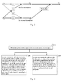
Fig. 3 shows the analysis of the optimal solution of a filter frequency domain in a single-filter structure. InFig. 3 , S1 represents a signal source and S2 represents a noise source. Since FIR (Finite Impulse Response) filter can indicate more accurately the transfer function from a signal source to microphones, in the analysis, FIR filters are used to simulate the channel transfer function H11 between a signal source and a first microphone, the channel transfer function H12 between a noise source and the first microphone, the channel transfer function H21 between the signal source and a second microphone, and the channel transfer function H22 between the noise source and the second microphone, respectively. The signal received by the first microphone is X1, and the signal received by the second microphone is X2, W is a filter, and Y1 is a signal with noises reduced. - The following equations can be obtained:


- Since noise source S2 will be completely eliminated when W is taken as the optimal solution, it can be inferred that the optimal solution of W is as shown in Equation 4:


- From Equation 5, it can be known that Y1 is a form of S1 that has been filtered in a certain mode and does not contain any component of S2.
- From the above-obtained optimal solution as W = H12/H22, it can be seen that the optimal solution of W is not a FIR filter. Nevertheless, in practice, in order to ensure the stability and easy realization of a filter, a FIR filter is usually used, though it may introduce a great error because a non-FIR filter cannot be well approached by a FIR filter.
- In a standard single-filter structure LMS algorithm, the optimal solution of a filter is a non-FIR filter. However, in practical application, the filter in this structure usually uses a FIR filter to approach this optimal solution, which may introduce a great error and cause poor noise elimination effect.
- The present invention provides a method and device for self-adaptively eliminating noises to address the problem that noise eliminating effect is poor in the prior art caused by the fact that FIR filter cannot approach the optimal solution for eliminating noises.
- The present invention discloses a method for self-adaptively eliminating noises, said method comprising:
- filtering the signal received by a first microphone using a first filter, filtering the signal received by a second microphone using a second filter, and obtaining a signal with noises reduced by subtracting the filtered signals;
- wherein, in a noise segment, the coefficient of the first filter and the coefficient of the second filter are updated respectively using the signal with noises reduced in the following manner: the ratio of the transfer function of the first filter to the transfer function of the second filter approaches the ratio of the channel transfer function between a noise source and the second microphone to the channel transfer function between the noise source and the first microphone; and
- in a noisy voice segment, the coefficient of the first filter and the coefficient of the second filter are remained unchanged respectively, the first filter uses a coefficient updated in the noise segment last time to filter the signal received by the first microphone, and the second filter uses a coefficient updated in the noise segment last time to filter the signal received by the second microphone;
- wherein, approaching the ratio of the transfer function of the first filter to the transfer function of the second filter to the ratio of the channel transfer function between the noise source and the second microphone to the channel transfer function between the noise source and the first microphone specifically comprises:
- approaching the transfer function of the first filter to the channel transfer function between the noise source and the second microphone, and approaching the transfer function of the second filter to the channel transfer function between the noise source and the first microphone;
- or,
- approaching the transfer function of the first filter to the product of the channel transfer function between the noise source and the second microphone and a constant, and approaching the transfer function of the second filter to the product of the channel transfer function between the noise source and the first microphone and the constant;
- wherein, updating the coefficient of the first filter and the coefficient of the second filter respectively using the signal with noises reduced specifically comprises:
- updating the coefficient of the first filter and the coefficient of the second filter respectively using the signal with noises reduced by means of least mean square algorithm or fast block least mean square algorithm.
- The present invention further discloses a device for self-adaptively eliminating noises, said device comprising: a first microphone, a second microphone, a first filter, a second filter, and a subtracter;
the first microphone inputting the received signal to the first filter, the first filter inputting the filtered signal to the subtracter;
the second microphone inputting the received signal to the second filter, the second filter inputting the filtered signal to the subtracter;
the subtracter subtracting the signals filtered by the first filter and the second filter to obtain a signal with noises reduced;
wherein, in a noise segment, the coefficient of the first filter and the coefficient of the second filter are updated respectively based on the signal with noises reduced in the following manner: the ratio of the transfer function of the first filter to the transfer function of the second filter approaches the ratio of the channel transfer function between a noise source and the second microphone to the channel transfer function between the noise source and the first microphone; and
in a noisy voice segment, the coefficient of the first filter and the coefficient of the second filter are remained unchanged respectively, the coefficient used by the first filter for filtering the signal received by the first microphone is a coefficient updated in the noise segment last time, and the coefficient used by the second filter for filtering the signal received by the second microphone is a coefficient updated in the noise segment last time. - The advantages of the present invention are: in a noise segment, updating the coefficients of the first and second filters respectively using the signal with noises reduced allows the noise component contained in the signal filtered by the first filter to tend to be the same with the noise component contained in the signal filtered by the second filter; and in a noisy voice segment, by means of remaining the coefficient of the first filter and the coefficient of the second filter unchanged, and filtering, by the first filter and the second filter, the signals received by the first microphone and the second microphone respectively using the coefficients updated in the noise segment last time, the noise components in the signal will offset each other when subtracting the signals filtered by the two filters, thereby enhancing the noise elimination effect.
-
-
Fig. 1 is a schematic diagram of a method for eliminating noises using a single filter in LMS of the prior art. -
Fig. 2 is a principle diagram of a method for eliminating noises using a single filter in LMS of the prior art. -
Fig. 3 is a schematic diagram analyzing the principle of the optimal solution in a frequency domain when using a single filter to eliminate noises in LMS of the prior art. -
Fig. 4 is a flowchart of a method for self-adaptively eliminating noises in an embodiment of the present invention. -
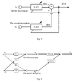
Fig. 5 is a principle diagram of a method for self-adaptively eliminating noises in an embodiment of the present invention. -
Fig. 6 is a schematic diagram analyzing the principle of a method for self-adaptively eliminating noises in an embodiment of the present invention. -
Fig. 7 is a time domain processing flowchart of a method for self-adaptively eliminating noises in an embodiment of the present invention. -
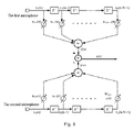
Fig. 8 is a schematic diagram of a method for self-adaptively eliminating noises in an embodiment of the present invention. -
Fig. 9 is a frequency domain processing flowchart of a method for self-adaptively eliminating noises in an embodiment of the present invention. -
Fig. 10 is a structural diagram of a device for self-adaptively eliminating noises in an embodiment of the present invention. - To make the object, technical solution and advantages of the present invention clearer, the embodiments of the present invention are described in further detail with reference to drawings.
-
Fig. 4 is a flowchart of a method for self-adaptively eliminating noises in the embodiment of the present invention. The method comprises the following steps: - Step S100: a first microphone receives a signal, and a second microphone receives a signal;
- Step S200: in a noise segment, the coefficient of the first filter and the coefficient of the second filter are updated respectively using the signal with noises reduced such that the noise component contained in the signal filtered by the first filter tends to be the same with the noise component contained in the signal filtered by the second filter; the signal received by the first microphone is filtered using the first filter, and the signal received by the second microphone is filtered using the second filter; and the signal with noises reduced is obtained by subtracting the filtered signals;
- Step S300: in a noisy voice segment, the coefficient of the first filter and the coefficient of the second filter are remained unchanged respectively; the first filter uses a coefficient updated in the noise segment last time to filter the signal received by the first microphone; and the second filter uses a coefficient updated in the noise segment last time to filter the signal received by the second microphone.
- In
Embodiment 2, the process of updating the filter is described as below: - in a noise segment, updating the coefficient of the first filter and the coefficient of the second filter specifically comprises: in a noise segment, updating the coefficient of the first filter and the coefficient of the second filter in the following manner:
- approaching the ratio of the transfer function of the first filter to the transfer function of the second filter to the ratio of the channel transfer function between a noise source and the second microphone to the channel transfer function between the noise source and the first microphone.
- In the following, the principle of the method for self-adaptively eliminating noises in this embodiment is described.
Fig. 5 is a principle diagram of a method for self-adaptively eliminating noises in the embodiment of the present invention.Fig. 6 is a schematic diagram analyzing the principle of a method for self-adaptively eliminating noises in the embodiment of the present invention. - Referring to
Fig. 6 , S1 represents a signal source, S2 represents a noise source, X1 is a frequency domain value of the signal received by the first microphone, X2 is a frequency domain value of the signal received by the second microphone, W1 and W2 are transfer functions of the first filter and the second filter respectively, and Y1 is a frequency domain value of the signal with noises reduced. - The following equations can be obtained:



- Since noise source S2 will be completely eliminated when W is taken as the optimal solution, there is a relationship between the two filters, W1 and W2, as indicated by Equation 9.

- When the relationship between the transfer functions of the two filters satisfies Equation 9, the signal with noises reduced is:

- Y1 is a form of S1 that has been filtered in a certain mode. Upon the above analysis, it can be known that Y1 does not contain any component of S2.
- In this embodiment, the ratio of the transfer function of the first filter to the transfer function of the second filter approaches the ratio of the channel transfer function between the noise source and the second microphone to the channel transfer function between the noise source and the first microphone in many ways.
- For example, the transfer function of the first filter approaches the channel transfer function between the noise source and the second microphone, and the transfer function of the second filter approaches the channel transfer function between the noise source and the first microphone.
-
Fig. 6 is a schematic diagram analyzing the principle of a method for self-adaptively eliminating noises in this example. - The transfer function of the first filter is W1, W1 = H22. The transfer function of the second filter is W2, W2 = H12. In this case, the noise components in the signals filtered by the two filters are the same. Thus, in this example, by approaching W1 to H22 and W2 to H12, it can be ensured that the noise components in the signals filtered by the two filters are as similar as possible, so as to effectively eliminate noises.
- For another example, the transfer function of the first filter approaches the product of the channel transfer function between the noise source and the second microphone and a constant, and the transfer function of the second filter approaches the product of the channel transfer function between the noise source and the first microphone and the constant. The constant may be a constant number or a transfer function. That is, W1 = H22 · H, W2 = H12 · H, where H is a transfer function or a constant number.
- In this example, it is also ensured that the noise components contained in the signals filtered by the first filter and the second filter are as similar as possible so as to effectively eliminate noises.
- Therein, the coefficient of the filter (the first filter or the second filter) is updated by means of least mean square algorithm or fast block least mean square algorithm such that the filter approaches a corresponding transfer function.
- Since the noises in the signal can be eliminated when the relationship between the transfer functions of the two filters satisfies Equation 9, the error introduced will be significantly reduced and the noise reduction effect will be greatly enhanced if two FIR filters are used to make their interrelationship approach Equation 9.
- In this manner, if every time the filter coefficient latest updated in the noise segment last time is used for filtering, the noise components in the signals filtered by the two filters will tend to be the same, and they will offset each other. Therefore, the noise component in the signal with noises reduced will be reduced constantly and the quality of the output voice will be constantly improved.
- In this embodiment, the coefficient of filters is updated using time domain LMS algorithm. The time domain processing flowchart of a method for self-adaptively eliminating noises in the embodiment of the present invention is as shown in
Fig. 7 . The schematic diagram of the method for self-adaptively eliminating noises in this embodiment is as shown inFig. 8 , wherein a dual-filter is used to eliminate noises. - Step S701, the first microphone and the second microphone respectively receive a signal.
- Step S702, whether the signal is a noise segment or not is determined, if it is, step S703 is performed; otherwise, step S704 is performed.
- If the signal is a signal of a noisy voice segment, the coefficient of the filters will not be updated and the filters use a coefficient updated in the noise segment last time.
- Step S703, the coefficients of the first and second filters are updated.
- Step S704, the signals are filtered in a time domain using the filters.
- Step S705, the signals filtered by the two filters are subtracted, and a signal with noised reduced is output.
- The process of updating the coefficients of the first and second filters in Step S703 is described in detail in below according to the schematic diagram of
Fig. 8 . - The filter coefficient in a dual-filter structure is updated using time domain LMS algorithm. The signal filtered by the first filter is y(n), which, as shown in
Equation 11, is a noisy signal of the input signal filtered by the first filter. The signal filtered by the second filter is d(n), which, as shown in Equation 12, is a noisy signal of the input signal filtered by the second filter. The signal output after subtracting the signals filtered by the two filters is e(n), which is as shown in Equation 13.


- The transfer function of the filters is updated using LMS algorithm. The transfer function of the first filter is updated according to Equation 14, and the transfer function of the second filter is updated according to Equation 15.


- In this embodiment, the coefficient of filters is updated using FBLMS algorithm by combining time and frequency domains. The frequency domain processing flowchart of a method for self-adaptively eliminating noises in this embodiment is as shown in
Fig. 9 . - Step S901, the first microphone and the second microphone respectively receive a signal.
- Step S902, the signals received by the first microphone and the second microphone are divided into blocks and converted into a frequency domain.
- Step S903, whether the signal is a noise segment or not is determined, if it is, step S904 is performed; otherwise, step S905 is performed.
- If the signal is a signal of a noisy voice segment, the coefficients of the filters will not be updated and the filters use coefficients updated in the noise segment last time.
- Step S904, the coefficients of the first and second filters are updated in a frequency domain.
- Step S905, the signals are filtered in the frequency domain, and the filtered signals are converted into a time domain.
- Step S906, the signals filtered by the two filters are subtracted, and a signal with noised reduced is output.
- Referring to the principle diagram of
Fig. 5 , the process of updating coefficients of the first and second filters in step S904 is described in detail. - In the following is given an equation for updating a filter by means of FBLMS algorithm using a dual-filter structure, where "*" represents convolution,
wherein, the signal filtered by the first filter is y(n), which, as shown in Equation 16, is a noisy signal of the input signal filtered by the first filter. The signal filtered by the second filter is d(n), which, as shown in Equation 17, is a noisy signal of the input signal filtered by the second filter. The signal output after subtracting the signals filtered by the two filters is e(n), which is as shown in Equation 18.


- Equation 18 is converted by means of FFT (Fast Fourier Transform) into a frequency domain as shown in Equation 19.

- The principle of using FBLMS algorithm is as the following equations:


- Based on Equation 22 and Equation 23, the filter coefficients are updated using FBLMS algorithm.
- Let two frequency domain filters with length of N be w F1(k) and w F1(k), N zeros are filled both before and after the signals received by the first microphone and the second microphone, and then the signals are divided into blocks to obtain block signals x̃ 1(k) and x2(k) with length of L+N-1, wherein N data overlap between the blocks.


-

Fig. 5 ; y(N : L + N - 1) are the last L elements of y(k) in Equation 26, which are corresponding to y(n) inFig. 5 ; and e(m) is a signal with noises reduced. -


-


- The filter transfer functions in Equation 30 and Equation 31 contain redundant data errors. By means of Equation 32 and Equation 33, zeros are filled after eliminating the redundant data errors from the transfer functions.
-
Fig. 10 is a structural diagram of a device for self-adaptively eliminating noises in the embodiment of the present invention. - The device comprises: a
first microphone 110, asecond microphone 120, afirst filter 210, asecond filter 220, and asubtracter 300;
thefirst microphone 110 inputs the received signal to thefirst filter 210, and thefirst filter 210 inputs the filtered signal to thesubtracter 300;
thesecond microphone 120 inputs the received signal to thesecond filter 220, and thesecond filter 220 inputs the filtered signal to thesubtracter 300;
thesubtracter 300 subtracts the signals filtered by thefirst filter 210 and thesecond filter 220 to obtain a signal with noises reduced;
wherein, in a noise segment, the coefficient of thefirst filter 210 and the coefficient of thesecond filter 220 are updated respectively based on the signal with noises reduced such that the noise component contained in the signal filtered by thefirst filter 210 tends to be the same with the noise component contained in the signal filtered by thesecond filter 220;
and, in a noisy voice segment, the coefficient of thefirst filter 210 and the coefficient of thesecond filter 220 are remained unchanged respectively, the coefficient used by thefirst filter 210 for filtering the signal received by thefirst microphone 110 is a coefficient updated in the noise segment last time, and the coefficient used by thesecond filter 220 for filtering the signal received by thesecond microphone 120 is a coefficient updated in the noise segment last time. - Further, the ratio of the transfer function of the
first filter 210 to the transfer function of thesecond filter 220 approaches the ratio of the channel transfer function between a noise source and thesecond microphone 120 to the channel transfer function between the noise source and thefirst microphone 110. - Further, the transfer function of the
first filter 210 approaches the channel transfer function between the noise source and thesecond microphone 120, and the transfer function of thesecond filter 220 approaches the channel transfer function between the noise source and thefirst microphone 110. - Further, the transfer function of the
first filter 210 approaches the product of the channel transfer function between the noise source and thesecond microphone 120 and a constant, and the transfer function of thesecond filter 220 approaches the product of the channel transfer function between the noise source and thefirst microphone 110 and the constant. - Furthermore, the coefficient of the
first filter 210 is updated by means of least mean square algorithm or fast block least mean square algorithm according to the signal with noises reduced; and
the coefficient of thesecond filter 220 is updated by means of least mean square algorithm or fast block least mean square algorithm according to the signal with noises reduced. - The foregoing is only preferred embodiments of the present invention, and they are not used for limiting the protection scope of the present invention. Any modification, equivalent replacement and improvement within the spirit and principles of the present invention should be included in the protection scope of the present invention.
Claims (8)
- A method for self-adaptively eliminating noises, characterized in that said method comprises:filtering the signal received by a first microphone using a first filter, filtering the signal received by a second microphone using a second filter, and obtaining a signal with noises reduced by subtracting the filtered signals;wherein, in a noise segment, the coefficient of the first filter and the coefficient of the second filter are updated respectively using the signal with noises reduced in the following manner: the ratio of the transfer function of the first filter to the transfer function of the second filter approaches the ratio of the channel transfer function between a noise source and the second microphone to the channel transfer function between the noise source and the first microphone; andin a noisy voice segment, the coefficient of the first filter and the coefficient of the second filter are remained unchanged respectively, the first filter uses a coefficient updated in the noise segment last time to filter the signal received by the first microphone, and the second filter uses a coefficient updated in the noise segment last time to filter the signal received by the second microphone.
- The method according to claim 1, characterized in that
approaching the ratio of the transfer function of the first filter to the transfer function of the second filter to the ratio of the channel transfer function between a noise source and the second microphone to the channel transfer function between the noise source and the first microphone specifically comprises:approaching the transfer function of the first filter to the channel transfer function between the noise source and the second microphone, and approaching the transfer function of the second filter to the channel transfer function between the noise source and the first microphone. - The method according to claim 1, characterized in that
approaching the ratio of the transfer function of the first filter to the transfer function of the second filter to the ratio of the channel transfer function between a noise source and the second microphone to the channel transfer function between the noise source and the first microphone specifically comprises:approaching the transfer function of the first filter to the product of the channel transfer function between the noise source and the second microphone and a constant, and approaching the transfer function of the second filter to the product of the channel transfer function between the noise source and the first microphone and the constant; - The method according to claim 1, characterized in that
updating the coefficient of the first filter and the coefficient of the second filter respectively using the signal with noises reduced specifically comprises:updating the coefficient of the first filter and the coefficient of the second filter respectively using the signal with noises reduced by means of least mean square algorithm or fast block least mean square algorithm. - A device for self-adaptively eliminating noises, characterized in that said device comprises: a first microphone, a second microphone, a first filter, a second filter, and a subtracter;
the first microphone configured to input a received signal to the first filter, the first filter configured to input the filtered signal to the subtracter;
the second microphone configured to input a received signal to the second filter, the second filter configured to input the filtered signal to the subtracter;
the subtracter configured to subtract the signals filtered by the first filter and the second filter to obtain a signal with noises reduced;
wherein, in a noise segment, the coefficient of the first filter and the coefficient of the second filter are updated respectively based on the signal with noises reduced in the following manner: the ratio of the transfer function of the first filter to the transfer function of the second filter approaches the ratio of the channel transfer function between a noise source and the second microphone to the channel transfer function between the noise source and the first microphone; and
in a noisy voice segment, the coefficient of the first filter and the coefficient of the second filter are remained unchanged respectively, the coefficient used by the first filter for filtering the signal received by the first microphone is a coefficient updated in the noise segment last time, and the coefficient used by the second filter for filtering the signal received by the second microphone is a coefficient updated in the noise segment last time. - The device according to claim 5, characterized in that
the transfer function of the first filter approaches the channel transfer function between a noise source and the second microphone, and the transfer function of the second filter approaches the channel transfer function between the noise source and the first microphone. - The device according to claim 5, characterized in that
the transfer function of the first filter approaches the product of the channel transfer function between the noise source and the second microphone and a constant, and the transfer function of the second filter approaches the product of the channel transfer function between the noise source and the first microphone and the constant. - The device according to claim 5, characterized in that
the coefficient of the first filter is updated by means of least mean square algorithm or fast block least mean square algorithm according to the signal with noises reduced; and
the coefficient of the second filter is updated by means of least mean square algorithm or fast block least mean square algorithm according to the signal with noises reduced.
Applications Claiming Priority (2)
| Application Number | Priority Date | Filing Date | Title |
|---|---|---|---|
| CN201210330475.8A CN102820036B (en) | 2012-09-07 | 2012-09-07 | Method and device for eliminating noises in self-adaption mode |
| PCT/CN2013/082791 WO2014036918A1 (en) | 2012-09-07 | 2013-09-02 | Method and device for self-adaptive noise reduction |
Publications (3)
| Publication Number | Publication Date |
|---|---|
| EP2814030A1 true EP2814030A1 (en) | 2014-12-17 |
| EP2814030A4 EP2814030A4 (en) | 2015-09-09 |
| EP2814030B1 EP2814030B1 (en) | 2016-11-09 |
Family
ID=47304121
Family Applications (1)
| Application Number | Title | Priority Date | Filing Date |
|---|---|---|---|
| EP13835187.9A Active EP2814030B1 (en) | 2012-09-07 | 2013-09-02 | Method and device for self-adaptive noise reduction |
Country Status (7)
| Country | Link |
|---|---|
| US (1) | US9570062B2 (en) |
| EP (1) | EP2814030B1 (en) |
| JP (1) | JP5762650B2 (en) |
| KR (1) | KR101538282B1 (en) |
| CN (1) | CN102820036B (en) |
| DK (1) | DK2814030T3 (en) |
| WO (1) | WO2014036918A1 (en) |
Families Citing this family (16)
| Publication number | Priority date | Publication date | Assignee | Title |
|---|---|---|---|---|
| CN102820036B (en) | 2012-09-07 | 2014-04-16 | 歌尔声学股份有限公司 | Method and device for eliminating noises in self-adaption mode |
| CN104581534B (en) * | 2015-01-22 | 2017-12-12 | 四川省阳子森环保设备有限公司 | A kind of efficient noise controller |
| CN106373586B (en) * | 2015-07-24 | 2020-03-17 | 南宁富桂精密工业有限公司 | Noise filtering circuit |
| CN105139853A (en) * | 2015-08-13 | 2015-12-09 | 深圳市双平泰科技有限公司 | Control method and control device for sign detector |
| WO2017147428A1 (en) * | 2016-02-25 | 2017-08-31 | Dolby Laboratories Licensing Corporation | Capture and extraction of own voice signal |
| CN108010543B (en) * | 2018-01-04 | 2024-02-23 | 澜邦科技(成都)集团有限公司 | A voltage-following low-distortion audio playback system |
| JP6635396B1 (en) | 2019-04-08 | 2020-01-22 | パナソニックIpマネジメント株式会社 | Acoustic noise suppression device and acoustic noise suppression method |
| CN112151002B (en) * | 2019-06-27 | 2024-02-23 | 株洲中车时代电气股份有限公司 | Noise reduction seat and noise reduction method |
| CN110970052B (en) * | 2019-12-31 | 2022-06-21 | 歌尔光学科技有限公司 | Noise reduction method and device, head-mounted display equipment and readable storage medium |
| CN112397080B (en) * | 2020-10-30 | 2023-02-28 | 浙江大华技术股份有限公司 | Echo cancellation method and apparatus, voice device, and computer-readable storage medium |
| US11398241B1 (en) * | 2021-03-31 | 2022-07-26 | Amazon Technologies, Inc. | Microphone noise suppression with beamforming |
| CN114007167B (en) * | 2021-10-29 | 2023-08-25 | 中电科航空电子有限公司 | Analog audio two-way communication system and communication method |
| US11741934B1 (en) | 2021-11-29 | 2023-08-29 | Amazon Technologies, Inc. | Reference free acoustic echo cancellation |
| CN114299998B (en) * | 2021-12-24 | 2025-06-03 | 北京声智科技有限公司 | Voice signal processing method, device, electronic device and storage medium |
| CN115188358A (en) * | 2022-07-21 | 2022-10-14 | 广东浦尔顿科技有限公司 | A noise processing method for a DC charging module |
| CN115841820A (en) * | 2023-02-23 | 2023-03-24 | 中国电子科技集团公司第十研究所 | Airborne voice processing platform |
Family Cites Families (16)
| Publication number | Priority date | Publication date | Assignee | Title |
|---|---|---|---|---|
| JP2950260B2 (en) * | 1996-11-22 | 1999-09-20 | 日本電気株式会社 | Noise suppression transmitter |
| JP2000312395A (en) * | 1999-04-28 | 2000-11-07 | Alpine Electronics Inc | Microphone system |
| ES2269137T3 (en) * | 1999-05-25 | 2007-04-01 | British Telecommunications Public Limited Company | CANCELLATION OF THE ACOUSTIC ECO. |
| US7206418B2 (en) * | 2001-02-12 | 2007-04-17 | Fortemedia, Inc. | Noise suppression for a wireless communication device |
| DE10118653C2 (en) * | 2001-04-14 | 2003-03-27 | Daimler Chrysler Ag | Method for noise reduction |
| CA2399159A1 (en) * | 2002-08-16 | 2004-02-16 | Dspfactory Ltd. | Convergence improvement for oversampled subband adaptive filters |
| KR100480789B1 (en) * | 2003-01-17 | 2005-04-06 | 삼성전자주식회사 | Method and apparatus for adaptive beamforming using feedback structure |
| US20080152157A1 (en) * | 2006-12-21 | 2008-06-26 | Vimicro Corporation | Method and system for eliminating noises in voice signals |
| US8503692B2 (en) | 2007-06-13 | 2013-08-06 | Aliphcom | Forming virtual microphone arrays using dual omnidirectional microphone array (DOMA) |
| CN101192411B (en) * | 2007-12-27 | 2010-06-02 | 北京中星微电子有限公司 | Large distance microphone array noise cancellation method and noise cancellation system |
| EP2196988B1 (en) * | 2008-12-12 | 2012-09-05 | Nuance Communications, Inc. | Determination of the coherence of audio signals |
| US9613632B2 (en) * | 2010-10-12 | 2017-04-04 | Nec Corporation | Signal processing device, signal processing method and signal processing program |
| JP5561195B2 (en) * | 2011-02-07 | 2014-07-30 | 株式会社Jvcケンウッド | Noise removing apparatus and noise removing method |
| CN102543060B (en) * | 2011-12-27 | 2014-03-12 | 瑞声声学科技(深圳)有限公司 | Active noise control system and design method thereof |
| CN102820036B (en) * | 2012-09-07 | 2014-04-16 | 歌尔声学股份有限公司 | Method and device for eliminating noises in self-adaption mode |
| CN202838949U (en) * | 2012-09-07 | 2013-03-27 | 歌尔声学股份有限公司 | Self-adaptive noise cancellation device |
-
2012
- 2012-09-07 CN CN201210330475.8A patent/CN102820036B/en active Active
-
2013
- 2013-09-02 JP JP2014555935A patent/JP5762650B2/en active Active
- 2013-09-02 EP EP13835187.9A patent/EP2814030B1/en active Active
- 2013-09-02 DK DK13835187.9T patent/DK2814030T3/en active
- 2013-09-02 US US14/412,080 patent/US9570062B2/en active Active
- 2013-09-02 WO PCT/CN2013/082791 patent/WO2014036918A1/en not_active Ceased
- 2013-09-02 KR KR1020147026030A patent/KR101538282B1/en active Active
Also Published As
| Publication number | Publication date |
|---|---|
| CN102820036A (en) | 2012-12-12 |
| DK2814030T3 (en) | 2017-02-13 |
| US9570062B2 (en) | 2017-02-14 |
| KR101538282B1 (en) | 2015-07-20 |
| CN102820036B (en) | 2014-04-16 |
| KR20140127331A (en) | 2014-11-03 |
| EP2814030B1 (en) | 2016-11-09 |
| WO2014036918A1 (en) | 2014-03-13 |
| JP5762650B2 (en) | 2015-08-12 |
| JP2015511330A (en) | 2015-04-16 |
| EP2814030A4 (en) | 2015-09-09 |
| US20150179160A1 (en) | 2015-06-25 |
Similar Documents
| Publication | Publication Date | Title |
|---|---|---|
| EP2814030B1 (en) | Method and device for self-adaptive noise reduction | |
| CN103329450B (en) | Echo cancellation device and echo detection device | |
| CN110598615B (en) | Data noise reduction method and system for monitoring bridge structure | |
| CN103222192A (en) | Signal processing device, signal processing method, and signal processing program | |
| CN108293170A (en) | Adaptive no phase distortion amplitude response in beam forming application is balanced | |
| CN102305945B (en) | Linear noise eliminating method | |
| US9319791B2 (en) | Reduced-delay subband signal processing system and method | |
| CN106688033B (en) | Noise reduction device, noise reduction method, and program | |
| Li et al. | Equivalent accuracy at a fraction of the cost: Overcoming temporal dispersion | |
| CN105825865A (en) | Echo cancellation method under noise environment and echo cancellation system thereof | |
| CN202838949U (en) | Self-adaptive noise cancellation device | |
| CN103327201B (en) | Residual echo removing method and system | |
| CN111402905B (en) | Audio data recovery method and device and Bluetooth device | |
| EP2730026B1 (en) | Low-delay filtering | |
| US20080152157A1 (en) | Method and system for eliminating noises in voice signals | |
| Brajović et al. | The DCT domain sparsity-assisted detection and recovery of impulsively disturbed samples | |
| CN115801145B (en) | Time delay estimation method and device for mixed signal and electronic equipment | |
| EP2811758A1 (en) | Audio signal mixing | |
| US9384757B2 (en) | Signal processing method, signal processing apparatus, and signal processing program | |
| KR101650951B1 (en) | Methods for separating mixed sigals | |
| Shimauchi et al. | Accurate adaptive filtering in square-root Hann windowed short-time fourier transform domain | |
| KR19990001296A (en) | Adaptive Noise Canceling Device and Method | |
| CN115862581A (en) | Secondary elimination method and system for repeated pattern noise | |
| Fujii et al. | Application of simultaneous equations method to ANC system with non-minimum phase secondary path | |
| CN105679326A (en) | Internet 3D stereo optimization system and method in weak environment |
Legal Events
| Date | Code | Title | Description |
|---|---|---|---|
| PUAI | Public reference made under article 153(3) epc to a published international application that has entered the european phase |
Free format text: ORIGINAL CODE: 0009012 |
|
| 17P | Request for examination filed |
Effective date: 20140910 |
|
| AK | Designated contracting states |
Kind code of ref document: A1 Designated state(s): AL AT BE BG CH CY CZ DE DK EE ES FI FR GB GR HR HU IE IS IT LI LT LU LV MC MK MT NL NO PL PT RO RS SE SI SK SM TR |
|
| AX | Request for extension of the european patent |
Extension state: BA ME |
|
| RA4 | Supplementary search report drawn up and despatched (corrected) |
Effective date: 20150807 |
|
| RIC1 | Information provided on ipc code assigned before grant |
Ipc: H04R 3/00 20060101ALI20150803BHEP Ipc: G10L 21/0208 20130101AFI20150803BHEP |
|
| 17Q | First examination report despatched |
Effective date: 20150914 |
|
| DAX | Request for extension of the european patent (deleted) | ||
| GRAP | Despatch of communication of intention to grant a patent |
Free format text: ORIGINAL CODE: EPIDOSNIGR1 |
|
| INTG | Intention to grant announced |
Effective date: 20160506 |
|
| GRAS | Grant fee paid |
Free format text: ORIGINAL CODE: EPIDOSNIGR3 |
|
| GRAA | (expected) grant |
Free format text: ORIGINAL CODE: 0009210 |
|
| AK | Designated contracting states |
Kind code of ref document: B1 Designated state(s): AL AT BE BG CH CY CZ DE DK EE ES FI FR GB GR HR HU IE IS IT LI LT LU LV MC MK MT NL NO PL PT RO RS SE SI SK SM TR |
|
| REG | Reference to a national code |
Ref country code: GB Ref legal event code: FG4D |
|
| REG | Reference to a national code |
Ref country code: AT Ref legal event code: REF Ref document number: 844591 Country of ref document: AT Kind code of ref document: T Effective date: 20161115 Ref country code: CH Ref legal event code: EP |
|
| REG | Reference to a national code |
Ref country code: IE Ref legal event code: FG4D |
|
| REG | Reference to a national code |
Ref country code: DE Ref legal event code: R096 Ref document number: 602013013977 Country of ref document: DE |
|
| REG | Reference to a national code |
Ref country code: DK Ref legal event code: T3 Effective date: 20170209 |
|
| PG25 | Lapsed in a contracting state [announced via postgrant information from national office to epo] |
Ref country code: LV Free format text: LAPSE BECAUSE OF FAILURE TO SUBMIT A TRANSLATION OF THE DESCRIPTION OR TO PAY THE FEE WITHIN THE PRESCRIBED TIME-LIMIT Effective date: 20161109 |
|
| REG | Reference to a national code |
Ref country code: LT Ref legal event code: MG4D |
|
| REG | Reference to a national code |
Ref country code: NL Ref legal event code: MP Effective date: 20161109 |
|
| REG | Reference to a national code |
Ref country code: AT Ref legal event code: MK05 Ref document number: 844591 Country of ref document: AT Kind code of ref document: T Effective date: 20161109 |
|
| PG25 | Lapsed in a contracting state [announced via postgrant information from national office to epo] |
Ref country code: GR Free format text: LAPSE BECAUSE OF FAILURE TO SUBMIT A TRANSLATION OF THE DESCRIPTION OR TO PAY THE FEE WITHIN THE PRESCRIBED TIME-LIMIT Effective date: 20170210 Ref country code: NL Free format text: LAPSE BECAUSE OF FAILURE TO SUBMIT A TRANSLATION OF THE DESCRIPTION OR TO PAY THE FEE WITHIN THE PRESCRIBED TIME-LIMIT Effective date: 20161109 Ref country code: NO Free format text: LAPSE BECAUSE OF FAILURE TO SUBMIT A TRANSLATION OF THE DESCRIPTION OR TO PAY THE FEE WITHIN THE PRESCRIBED TIME-LIMIT Effective date: 20170209 Ref country code: SE Free format text: LAPSE BECAUSE OF FAILURE TO SUBMIT A TRANSLATION OF THE DESCRIPTION OR TO PAY THE FEE WITHIN THE PRESCRIBED TIME-LIMIT Effective date: 20161109 Ref country code: LT Free format text: LAPSE BECAUSE OF FAILURE TO SUBMIT A TRANSLATION OF THE DESCRIPTION OR TO PAY THE FEE WITHIN THE PRESCRIBED TIME-LIMIT Effective date: 20161109 |
|
| PG25 | Lapsed in a contracting state [announced via postgrant information from national office to epo] |
Ref country code: PT Free format text: LAPSE BECAUSE OF FAILURE TO SUBMIT A TRANSLATION OF THE DESCRIPTION OR TO PAY THE FEE WITHIN THE PRESCRIBED TIME-LIMIT Effective date: 20170309 Ref country code: FI Free format text: LAPSE BECAUSE OF FAILURE TO SUBMIT A TRANSLATION OF THE DESCRIPTION OR TO PAY THE FEE WITHIN THE PRESCRIBED TIME-LIMIT Effective date: 20161109 Ref country code: ES Free format text: LAPSE BECAUSE OF FAILURE TO SUBMIT A TRANSLATION OF THE DESCRIPTION OR TO PAY THE FEE WITHIN THE PRESCRIBED TIME-LIMIT Effective date: 20161109 Ref country code: PL Free format text: LAPSE BECAUSE OF FAILURE TO SUBMIT A TRANSLATION OF THE DESCRIPTION OR TO PAY THE FEE WITHIN THE PRESCRIBED TIME-LIMIT Effective date: 20161109 Ref country code: IS Free format text: LAPSE BECAUSE OF FAILURE TO SUBMIT A TRANSLATION OF THE DESCRIPTION OR TO PAY THE FEE WITHIN THE PRESCRIBED TIME-LIMIT Effective date: 20170309 Ref country code: RS Free format text: LAPSE BECAUSE OF FAILURE TO SUBMIT A TRANSLATION OF THE DESCRIPTION OR TO PAY THE FEE WITHIN THE PRESCRIBED TIME-LIMIT Effective date: 20161109 Ref country code: HR Free format text: LAPSE BECAUSE OF FAILURE TO SUBMIT A TRANSLATION OF THE DESCRIPTION OR TO PAY THE FEE WITHIN THE PRESCRIBED TIME-LIMIT Effective date: 20161109 Ref country code: AT Free format text: LAPSE BECAUSE OF FAILURE TO SUBMIT A TRANSLATION OF THE DESCRIPTION OR TO PAY THE FEE WITHIN THE PRESCRIBED TIME-LIMIT Effective date: 20161109 |
|
| PG25 | Lapsed in a contracting state [announced via postgrant information from national office to epo] |
Ref country code: RO Free format text: LAPSE BECAUSE OF FAILURE TO SUBMIT A TRANSLATION OF THE DESCRIPTION OR TO PAY THE FEE WITHIN THE PRESCRIBED TIME-LIMIT Effective date: 20161109 Ref country code: EE Free format text: LAPSE BECAUSE OF FAILURE TO SUBMIT A TRANSLATION OF THE DESCRIPTION OR TO PAY THE FEE WITHIN THE PRESCRIBED TIME-LIMIT Effective date: 20161109 Ref country code: SK Free format text: LAPSE BECAUSE OF FAILURE TO SUBMIT A TRANSLATION OF THE DESCRIPTION OR TO PAY THE FEE WITHIN THE PRESCRIBED TIME-LIMIT Effective date: 20161109 Ref country code: CZ Free format text: LAPSE BECAUSE OF FAILURE TO SUBMIT A TRANSLATION OF THE DESCRIPTION OR TO PAY THE FEE WITHIN THE PRESCRIBED TIME-LIMIT Effective date: 20161109 |
|
| REG | Reference to a national code |
Ref country code: DE Ref legal event code: R097 Ref document number: 602013013977 Country of ref document: DE |
|
| PG25 | Lapsed in a contracting state [announced via postgrant information from national office to epo] |
Ref country code: BE Free format text: LAPSE BECAUSE OF FAILURE TO SUBMIT A TRANSLATION OF THE DESCRIPTION OR TO PAY THE FEE WITHIN THE PRESCRIBED TIME-LIMIT Effective date: 20161109 Ref country code: IT Free format text: LAPSE BECAUSE OF FAILURE TO SUBMIT A TRANSLATION OF THE DESCRIPTION OR TO PAY THE FEE WITHIN THE PRESCRIBED TIME-LIMIT Effective date: 20161109 Ref country code: BG Free format text: LAPSE BECAUSE OF FAILURE TO SUBMIT A TRANSLATION OF THE DESCRIPTION OR TO PAY THE FEE WITHIN THE PRESCRIBED TIME-LIMIT Effective date: 20170209 Ref country code: SM Free format text: LAPSE BECAUSE OF FAILURE TO SUBMIT A TRANSLATION OF THE DESCRIPTION OR TO PAY THE FEE WITHIN THE PRESCRIBED TIME-LIMIT Effective date: 20161109 |
|
| PLBE | No opposition filed within time limit |
Free format text: ORIGINAL CODE: 0009261 |
|
| STAA | Information on the status of an ep patent application or granted ep patent |
Free format text: STATUS: NO OPPOSITION FILED WITHIN TIME LIMIT |
|
| REG | Reference to a national code |
Ref country code: FR Ref legal event code: PLFP Year of fee payment: 5 |
|
| 26N | No opposition filed |
Effective date: 20170810 |
|
| PG25 | Lapsed in a contracting state [announced via postgrant information from national office to epo] |
Ref country code: SI Free format text: LAPSE BECAUSE OF FAILURE TO SUBMIT A TRANSLATION OF THE DESCRIPTION OR TO PAY THE FEE WITHIN THE PRESCRIBED TIME-LIMIT Effective date: 20161109 |
|
| REG | Reference to a national code |
Ref country code: CH Ref legal event code: PL |
|
| PG25 | Lapsed in a contracting state [announced via postgrant information from national office to epo] |
Ref country code: MC Free format text: LAPSE BECAUSE OF FAILURE TO SUBMIT A TRANSLATION OF THE DESCRIPTION OR TO PAY THE FEE WITHIN THE PRESCRIBED TIME-LIMIT Effective date: 20161109 |
|
| REG | Reference to a national code |
Ref country code: IE Ref legal event code: MM4A |
|
| PG25 | Lapsed in a contracting state [announced via postgrant information from national office to epo] |
Ref country code: LU Free format text: LAPSE BECAUSE OF NON-PAYMENT OF DUE FEES Effective date: 20170902 |
|
| PG25 | Lapsed in a contracting state [announced via postgrant information from national office to epo] |
Ref country code: CH Free format text: LAPSE BECAUSE OF NON-PAYMENT OF DUE FEES Effective date: 20170930 Ref country code: LI Free format text: LAPSE BECAUSE OF NON-PAYMENT OF DUE FEES Effective date: 20170930 Ref country code: IE Free format text: LAPSE BECAUSE OF NON-PAYMENT OF DUE FEES Effective date: 20170902 |
|
| REG | Reference to a national code |
Ref country code: FR Ref legal event code: PLFP Year of fee payment: 6 |
|
| PG25 | Lapsed in a contracting state [announced via postgrant information from national office to epo] |
Ref country code: MT Free format text: LAPSE BECAUSE OF NON-PAYMENT OF DUE FEES Effective date: 20170902 |
|
| PG25 | Lapsed in a contracting state [announced via postgrant information from national office to epo] |
Ref country code: HU Free format text: LAPSE BECAUSE OF FAILURE TO SUBMIT A TRANSLATION OF THE DESCRIPTION OR TO PAY THE FEE WITHIN THE PRESCRIBED TIME-LIMIT; INVALID AB INITIO Effective date: 20130902 |
|
| PG25 | Lapsed in a contracting state [announced via postgrant information from national office to epo] |
Ref country code: CY Free format text: LAPSE BECAUSE OF FAILURE TO SUBMIT A TRANSLATION OF THE DESCRIPTION OR TO PAY THE FEE WITHIN THE PRESCRIBED TIME-LIMIT Effective date: 20161109 |
|
| PG25 | Lapsed in a contracting state [announced via postgrant information from national office to epo] |
Ref country code: MK Free format text: LAPSE BECAUSE OF FAILURE TO SUBMIT A TRANSLATION OF THE DESCRIPTION OR TO PAY THE FEE WITHIN THE PRESCRIBED TIME-LIMIT Effective date: 20161109 |
|
| PG25 | Lapsed in a contracting state [announced via postgrant information from national office to epo] |
Ref country code: TR Free format text: LAPSE BECAUSE OF FAILURE TO SUBMIT A TRANSLATION OF THE DESCRIPTION OR TO PAY THE FEE WITHIN THE PRESCRIBED TIME-LIMIT Effective date: 20161109 |
|
| PG25 | Lapsed in a contracting state [announced via postgrant information from national office to epo] |
Ref country code: AL Free format text: LAPSE BECAUSE OF FAILURE TO SUBMIT A TRANSLATION OF THE DESCRIPTION OR TO PAY THE FEE WITHIN THE PRESCRIBED TIME-LIMIT Effective date: 20161109 |
|
| PGFP | Annual fee paid to national office [announced via postgrant information from national office to epo] |
Ref country code: DK Payment date: 20250829 Year of fee payment: 13 Ref country code: DE Payment date: 20250916 Year of fee payment: 13 |
|
| PGFP | Annual fee paid to national office [announced via postgrant information from national office to epo] |
Ref country code: GB Payment date: 20250919 Year of fee payment: 13 |
|
| PGFP | Annual fee paid to national office [announced via postgrant information from national office to epo] |
Ref country code: FR Payment date: 20250929 Year of fee payment: 13 |