EP2813458A1 - Method and apparatus for estimating the weight of an elevator car - Google Patents
Method and apparatus for estimating the weight of an elevator car Download PDFInfo
- Publication number
- EP2813458A1 EP2813458A1 EP13171256.4A EP13171256A EP2813458A1 EP 2813458 A1 EP2813458 A1 EP 2813458A1 EP 13171256 A EP13171256 A EP 13171256A EP 2813458 A1 EP2813458 A1 EP 2813458A1
- Authority
- EP
- European Patent Office
- Prior art keywords
- elevator
- elevator car
- mass
- estimate
- control system
- Prior art date
- Legal status (The legal status is an assumption and is not a legal conclusion. Google has not performed a legal analysis and makes no representation as to the accuracy of the status listed.)
- Withdrawn
Links
- 238000000034 method Methods 0.000 title claims description 21
- SAZUGELZHZOXHB-UHFFFAOYSA-N acecarbromal Chemical compound CCC(Br)(CC)C(=O)NC(=O)NC(C)=O SAZUGELZHZOXHB-UHFFFAOYSA-N 0.000 claims description 3
- 238000004590 computer program Methods 0.000 claims description 3
- 230000015654 memory Effects 0.000 claims description 3
- 230000005484 gravity Effects 0.000 description 3
- 238000003384 imaging method Methods 0.000 description 3
- 238000005303 weighing Methods 0.000 description 3
- 230000008901 benefit Effects 0.000 description 2
- 230000001133 acceleration Effects 0.000 description 1
- 238000004891 communication Methods 0.000 description 1
- 230000007423 decrease Effects 0.000 description 1
- 238000009826 distribution Methods 0.000 description 1
- 238000005516 engineering process Methods 0.000 description 1
- 230000006870 function Effects 0.000 description 1
- 238000010801 machine learning Methods 0.000 description 1
- 238000004519 manufacturing process Methods 0.000 description 1
- 238000010295 mobile communication Methods 0.000 description 1
- 230000003287 optical effect Effects 0.000 description 1
Images


Classifications
-
- B—PERFORMING OPERATIONS; TRANSPORTING
- B66—HOISTING; LIFTING; HAULING
- B66B—ELEVATORS; ESCALATORS OR MOVING WALKWAYS
- B66B1/00—Control systems of elevators in general
- B66B1/34—Details, e.g. call counting devices, data transmission from car to control system, devices giving information to the control system
- B66B1/3476—Load weighing or car passenger counting devices
-
- B—PERFORMING OPERATIONS; TRANSPORTING
- B66—HOISTING; LIFTING; HAULING
- B66B—ELEVATORS; ESCALATORS OR MOVING WALKWAYS
- B66B1/00—Control systems of elevators in general
- B66B1/24—Control systems with regulation, i.e. with retroactive action, for influencing travelling speed, acceleration, or deceleration
- B66B1/28—Control systems with regulation, i.e. with retroactive action, for influencing travelling speed, acceleration, or deceleration electrical
- B66B1/30—Control systems with regulation, i.e. with retroactive action, for influencing travelling speed, acceleration, or deceleration electrical effective on driving gear, e.g. acting on power electronics, on inverter or rectifier controlled motor
- B66B1/304—Control systems with regulation, i.e. with retroactive action, for influencing travelling speed, acceleration, or deceleration electrical effective on driving gear, e.g. acting on power electronics, on inverter or rectifier controlled motor with starting torque control
Definitions
- the present invention relates generally to elevators and measuring masses and forces that affect the operation of elevators.
- a typical elevator includes an elevator car, a hoisting machine for moving the elevator car, at least one counter weight, and traction means such as a rope, cable, chain, or belt.
- the traction means connect the elevator car and the at least one counter weight to each other.
- the traction means pass through a traction sheave which is connected to the hoisting machine, for example, to a drive shaft of the hoisting machine.
- An elevator can be manufactured also without counter weight.
- An elevator group comprises at least two elevators.
- a typical elevator group comprises adjacent elevators in the same building and in some cases the elevators are controlled by using information received from a destination control system.
- a destination control system When using a destination control system a passenger registers his floor call (to which floor he is destined to go) before entering an elevator car. After the user has selected the desired floor, the system informs the passenger to which elevator car he should go, or which elevator car he should wait for.
- One advantage of the destination control system is that it reduces an average travel time because the elevator car makes fewer stops for individual passengers. A run of an elevator car starts when a brake of the hoisting machine is released and the elevator car starts moving.
- the weight the elevator car is measured by a weighing device attached, for example, to the elevator ropes, car floor, hoisting machine or brake and a torque necessary to keep the elevator car in its position is applied on the traction sheave for providing smooth start.
- the run ends when the elevator car stops.
- Elevator systems are complex, expensive and energy consuming products. Thus, it is always desirable to make it cheaper to manufacture and operate without sacrificing convenience for users.
- the present invention relates generally to elevators and measuring masses or forces that affect the elevators.
- the information acquired from destination control system can be used for multiple purposes.
- One purpose is to estimate the weight of an elevator car. This is done by counting the number of passengers in the elevator car from the call allocations gathered by the destination control system. The estimate can be then used in controlling movements of an elevator comfortably, particularly in a situation wherein smooth start is desired after releasing the brake of the elevator.
- the invention is implemented as a method for controlling movement of an elevator.
- the elevator is connected to a destination control system.
- the destination control system may be implemented as a centralized system or a distributed system.
- the collected data is processed and maintained at a centralized location.
- the present invention is suitable for both types of destination control system.
- first destination calls from elevator passengers are received and allocated to elevators of an elevator group. A number of passengers in each elevator car is then calculated on the basis of these call allocations.
- the properties for a run for the elevator are calculated from these call allocations. Properties typical include typically at least the start and destination floors.
- the collected properties are maintained at least until the run is over, however, it may also be stored for later use, such as statistics and machine learning.
- Based on the collected properties the number of passengers can be counted for each start of the elevator and a mass of a load in the elevator car can be estimated. Based on the estimated mass, an estimate of torque for the traction sheave of the elevator hoisting machine required to keep said elevator stationary, is then computed. Lastly the torque is applied to the elevator hoisting machine when releasing the brake.
- the method described above is implemented as a computer program.
- One aspect of the invention is thus to provide an alternative method for weighting masses affecting an elevator.
- the method utilizes information obtainable from a destination control system.
- the system collects data about destination calls allocated to the first elevator car.
- the system allows at most an allowed maximum number of passengers to use the elevator car in the same time.
- An overload sensor prohibits the run, if there is overload in the elevator car.
- the counted number of passengers is multiplied by an average mass of a passenger resulting in an estimate about the mass of the load.
- the collected data of calls and the average mass of a passenger are utilized when calculating other physical quantities than mass.
- a torque is, for example, one of these quantities.
- the invention is implemented as an apparatus for controlling an elevator.
- the apparatus comprises at least one processor and program code stored in at least one memory, wherein said apparatus is configured to receive call allocations for said elevator, estimate an a mass of a load in the elevator car based on said call allocations, compute an estimate of torque required to keep said elevator stationary and apply torque based on said estimate of torque to said elevator when releasing the brake of said elevator before accelerating movement.
- the invention is implemented as a system comprising a plurality of elevators connected to the same destination control system and being controlled by a device described above, wherein the destination control system may be centralized or distributed.
- the invention is implemented as a computer program that is configured to cause the method described above when executed in an apparatus as described above.
- the benefit of the invention is that the expensive weighing device of the elevator can be avoided.
- elevators include a counter-weight.
- the present invention can be used also in systems having distributed destination control system, centralized destination control system or single elevator destination control system.
- the counter-weight of the elevator is not necessary for the invention but the invention works also with counter-weightless elevators.
- Figure 1A shows an elevator group comprising a first elevator car 1, a first hoisting machine 2 for moving the first elevator car 1, a second elevator car 3, a second hoisting machine 4 for moving the second elevator car 3, and a destination control system 5.
- the destination control system 5 receives destination calls from passengers and part of those calls relate to the next run of the first elevator car 1. At most an allowed maximum number of passengers may use the first elevator car 1 at the same time.
- the destination control system 5 is placed in FIG. 1A in connection with the second hoisting machine 4 but it could be placed somewhere else.
- the elevator car 1 is connected with traction means 7, such as a rope, cable, chain, or belt, to a counter weight 6.
- traction means 7 pass from the counter weight 6 through a diverting pulley 8 and traction sheave 9 to the elevator car 1.
- the traction sheave 9 is connected to the drive shaft of the hoisting machine 2 and the hoisting machine 2 is attached to the top of a first hoistway 11.
- the second elevator car 3 is connected with traction means to another counter weight.
- the first elevator car 1 is movable (up and down) in the first hoistway 11 and the second elevator car 2 is movable in the second hoistway 12.
- the elevators of the elevator group are similar but they could include some differences.
- the mass of the counter-weight corresponds with the weight of the half loaded first elevator car 1.
- the counter weight 6 aims to move downwards due to gravity, but the brake mechanism of the hoisting machine 2 keeps the counter weight 6 in its current location (in the hoistway 11).
- the mass distribution mentioned above is typical, however, it is not the only option but the mass of the counter weight 6 may be chosen according to the need.
- the elevator may be constructed without counter-weight.
- FIG 1B shows another embodiment in which only one passenger is drawn in Figure 1B in each elevator car 1 and 2 for illustration purpose but in this embodiment it is assumed that the elevator cars 1 and 2 carry maximum allowable loads. Now, because of gravity, the elevator car 1 aims to move downwards but the brake of the hoisting machine 2 prohibits the movement. Naturally it is possible that the elevator car together with the load weights exactly as much as the counter weight, however, it is a rare situation.
- the elevators are of different types, wherein the second elevator 3 car is connected to support means but the first elevator car 1 is not.
- the example elevators of the elevator group are not located besides each other but in different parts of a building or even in different buildings.
- the present invention may also be applied only to some of the elevators in the elevator group. Such a situation may emerge, for example, when new elevator is added to the group or at least one of the elevators within group is replaced.
- the destination control system 20 comprises a first wiring 21 through which it obtains calls from passengers, including the calls for the run in the first elevator car 1.
- the first wiring is connected to panels located on each floor. Those panels include a set of buttons by which the passengers make elevator calls (the panels are omitted from the figure).
- a second wiring 27 is for communication between the destination control system 20 and the apparatus 23.
- the destination control system 20 triggers the operation of the apparatus 23 by sending information through the wiring 605 to the apparatus 23.
- This information includes the number of calls for an elevator car (1 or 3) and run information.
- the run information discloses a direction of the run (upwards or downwards) and a length of the run.
- the length of the run may be given, for example, as a number of floors or in meters, which is derivable from the number of floors.
- a third wiring 28 is for electric current.
- a grid 29 feeds a supply centre 210 which feeds through the third wiring 28 a first hoisting machine 2 as well as a second hoisting machine 4.
- a fourth wiring 22 is for commands by which the destination control system 5 controls the elevators.
- One example of the commands is a command to use a hoisting machine with the appropriate energy amount. Generally speaking, the commands concern the starting and stopping of hoisting machines.
- the apparatus 23 obtains from the destination control system 5 such run information according to which the first elevator car 2 is to be moved upwards to the top floor in the first hoistway 11 and the second elevator car 4 is to be moved downwards to the bottom floor in the second hoistway 12.
- the apparatus 23 obtains the number of calls for the run in the first elevator car 1 and the number of calls for the run in the second elevator car 3.
- the mass of the first elevator car 1 is as empty 50% of the mass of the counter weight 6 and the same balancing is used in the second elevator.
- the allowed maximum number of passengers is six for the both elevator cars 1 and 2.
- the apparatus 23 is fully integrated into the destination control system 5.
- the second wiring 27 is not needed, i.e. it is omitted.
- a method according to the present invention starts by collecting call allocations for a run, step 30.
- a person calls for a run, he will choose from the destination control system the floor he is wishing to travel.
- the person calling may provide the information about the number of passengers travelling with him.
- the destination control system knows the start and the destination of the run. Call allocations are maintained until the run is over so that they are available for every start during the run.
- step 31 Based on that information it is possible to estimate the number of passengers in an elevator car, step 31.
- the estimation is possible as the destination control system knows for each person travelling start and destination floors. From this information the current number of person travelling can be calculated. Thus, when the elevator is starting the run it knows how many persons it is carrying. Based on the number of persons it is possible to estimate the weight of an elevator car, step 32.
- step 33 Based on the estimated weight of an elevator car it is possible to determine what is the torque required to keep the elevator stationary, step 33. As explained with regard to figures 1 and 2 , the direction of force caused by gravity varies depending on the number of passengers, however, in order to provide comfortable ride the elevator car needs to be hold in its position in both cases. This is done by applying the determined torque, step 34.
- step 35 After releasing the brake the elevator car does not move before the acceleration is initiated.
- the actual release step and applying step are done accordingly as in the cases wherein weight of the elevator car is measured with a weighing device.
- the estimate used in the present invention is accurate enough for the purpose and smooth start can be provided. It is reminded here that for security reasons an overload sensor must be used for measuring that the maximum allowable weight is not exceeded, however, a person skilled in the art understands that these devices are configured to detect that the threshold value is not exceeded and cannot be used for the purposes of the present invention.
- the estimating step 32 comprises multiplying a predefined average mass of a passenger with said number resulting in the mass of the load. For example, if said number (of the passengers) is five and the predefined average mass of a passenger is 80 kg, the multiplication results in that the mass of the load is 400 kg.
- the predefined average mass may be different in different countries.
- the destination control system is controlled with personal control device, such as a badge.
- personal data such as the weight of the person may be included.
- the badge mentioned above is only one example of collecting personal data.
- the estimated weight of the person may be improved by using other means. For example, it is possible to use imaging systems. Then, from the image the height and the figure of the person can be determined. Then, based on the height and figure weight can be estimated.
- imaging devices such as digital camera, can be used for counting the number of people entering to the elevator car. Instead of imaging devices other devices may be used in estimating the number of passengers and their weight.
- a feedback function is used. If the elevator car starts to move into wrong direction the hoisting device increases or decreases the used torque rapidly but softly so that the best possible comfort is achieved.
- the above mentioned method may be implemented as computer software which is executed in a destination control system, such as the apparatus disclosed above.
- a destination control system such as the apparatus disclosed above.
- the software When the software is executed in a computing device it is configured to perform the above described inventive method in order to facilitate discovery resources in a mobile communication network.
- the software is embodied on a computer readable medium so that it can be provided to the computing device.
- the components of the exemplary embodiments can include computer readable medium or memories for holding instructions programmed according to the teachings of the present inventions and for holding data structures, tables, records, and/or other data described herein.
- Computer readable medium can include any suitable medium that participates in providing instructions to a processor for execution.
- Common forms of computer-readable media include, for example, a floppy disk, a flexible disk, hard disk, magnetic tape, any other suitable magnetic medium, a CD-ROM, CD ⁇ R, CD ⁇ RW, DVD, DVD-RAM, DVD ⁇ RW, DVD ⁇ R, HD DVD, HD DVD-R, HD DVD-RW, HD DVD-RAM, Blu-ray Disc, any other suitable optical medium, suitable memory chip or cartridge.
Landscapes
- Engineering & Computer Science (AREA)
- Automation & Control Theory (AREA)
- Mechanical Engineering (AREA)
- Computer Networks & Wireless Communication (AREA)
- Elevator Control (AREA)
Abstract
The present invention relates generally to elevators and measuring masses or forces that affect the elevators. The information acquired from destination control system can be used for multiple purposes. One purpose is to estimate the weight of an elevator car. This is done by counting the number of passengers in the elevator car from the information gathered by the destination control system. The estimate can be the used in controlling movements of an elevator comfortably, particularly in a situation wherein smooth start is desired after releasing the brake of the elevator.
Description
- The present invention relates generally to elevators and measuring masses and forces that affect the operation of elevators.
- A typical elevator includes an elevator car, a hoisting machine for moving the elevator car, at least one counter weight, and traction means such as a rope, cable, chain, or belt. The traction means connect the elevator car and the at least one counter weight to each other. The traction means pass through a traction sheave which is connected to the hoisting machine, for example, to a drive shaft of the hoisting machine. An elevator can be manufactured also without counter weight.
- An elevator group comprises at least two elevators. A typical elevator group comprises adjacent elevators in the same building and in some cases the elevators are controlled by using information received from a destination control system. When using a destination control system a passenger registers his floor call (to which floor he is destined to go) before entering an elevator car. After the user has selected the desired floor, the system informs the passenger to which elevator car he should go, or which elevator car he should wait for. One advantage of the destination control system is that it reduces an average travel time because the elevator car makes fewer stops for individual passengers. A run of an elevator car starts when a brake of the hoisting machine is released and the elevator car starts moving. Typically this is done so that the weight the elevator car is measured by a weighing device attached, for example, to the elevator ropes, car floor, hoisting machine or brake and a torque necessary to keep the elevator car in its position is applied on the traction sheave for providing smooth start. The run ends when the elevator car stops.
- Elevator systems are complex, expensive and energy consuming products. Thus, it is always desirable to make it cheaper to manufacture and operate without sacrificing convenience for users.
- The present invention relates generally to elevators and measuring masses or forces that affect the elevators. The information acquired from destination control system can be used for multiple purposes. One purpose is to estimate the weight of an elevator car. This is done by counting the number of passengers in the elevator car from the call allocations gathered by the destination control system. The estimate can be then used in controlling movements of an elevator comfortably, particularly in a situation wherein smooth start is desired after releasing the brake of the elevator.
- In an embodiment the invention is implemented as a method for controlling movement of an elevator. The elevator is connected to a destination control system. A person skilled in the art understands that the destination control system may be implemented as a centralized system or a distributed system. In a centralized system the collected data is processed and maintained at a centralized location. In a distributed implementation there is a plurality of units that are configured to communicate with each other in order to provide the required functionality. The present invention is suitable for both types of destination control system. In the method, first destination calls from elevator passengers are received and allocated to elevators of an elevator group. A number of passengers in each elevator car is then calculated on the basis of these call allocations.
- The properties for a run for the elevator are calculated from these call allocations. Properties typical include typically at least the start and destination floors. The collected properties are maintained at least until the run is over, however, it may also be stored for later use, such as statistics and machine learning. Based on the collected properties the number of passengers can be counted for each start of the elevator and a mass of a load in the elevator car can be estimated. Based on the estimated mass, an estimate of torque for the traction sheave of the elevator hoisting machine required to keep said elevator stationary, is then computed. Lastly the torque is applied to the elevator hoisting machine when releasing the brake. In a further embodiment the method described above is implemented as a computer program.
- One aspect of the invention is thus to provide an alternative method for weighting masses affecting an elevator. The method utilizes information obtainable from a destination control system. The system collects data about destination calls allocated to the first elevator car. The system allows at most an allowed maximum number of passengers to use the elevator car in the same time. An overload sensor prohibits the run, if there is overload in the elevator car. In one embodiment of the method, the counted number of passengers is multiplied by an average mass of a passenger resulting in an estimate about the mass of the load. In other embodiments of the method the collected data of calls and the average mass of a passenger are utilized when calculating other physical quantities than mass. A torque is, for example, one of these quantities.
- In one embodiment the invention is implemented as an apparatus for controlling an elevator. The apparatus comprises at least one processor and program code stored in at least one memory, wherein said apparatus is configured to receive call allocations for said elevator, estimate an a mass of a load in the elevator car based on said call allocations, compute an estimate of torque required to keep said elevator stationary and apply torque based on said estimate of torque to said elevator when releasing the brake of said elevator before accelerating movement.
- In a further embodiment the invention is implemented as a system comprising a plurality of elevators connected to the same destination control system and being controlled by a device described above, wherein the destination control system may be centralized or distributed.
- In a further embodiment the invention is implemented as a computer program that is configured to cause the method described above when executed in an apparatus as described above.
- The benefit of the invention is that the expensive weighing device of the elevator can be avoided.
- The drawings constitute a part of this specification and include some exemplary embodiments of the invention.
-
Figure 1A shows an elevator group in which elevator cars are empty. -
Figure 1B shows the elevator group in which the elevator cars are loaded. -
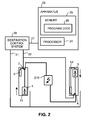
Figure 2 illustrates an example embodiment of the present invention, -
Figure 3 illustrates a method according to an embodiment of the invention. - It is appreciated that the following embodiments are exemplary. Although the specification may refer to "one" or "some" embodiment(s), the reference is not necessarily made to the same embodiment(s), or the feature in question may apply to multiple embodiments. Single features of different embodiments may be combined to provide further embodiments.
- In the following examples of a common elevator group comprising centralized destination control system are disclosed. Furthermore, in the examples elevators include a counter-weight. However, the present invention can be used also in systems having distributed destination control system, centralized destination control system or single elevator destination control system. Furthermore, the counter-weight of the elevator is not necessary for the invention but the invention works also with counter-weightless elevators.
-
Figure 1A shows an elevator group comprising afirst elevator car 1, afirst hoisting machine 2 for moving thefirst elevator car 1, asecond elevator car 3, asecond hoisting machine 4 for moving thesecond elevator car 3, and adestination control system 5. Thedestination control system 5 receives destination calls from passengers and part of those calls relate to the next run of thefirst elevator car 1. At most an allowed maximum number of passengers may use thefirst elevator car 1 at the same time. Thedestination control system 5 is placed inFIG. 1A in connection with thesecond hoisting machine 4 but it could be placed somewhere else. Theelevator car 1 is connected with traction means 7, such as a rope, cable, chain, or belt, to acounter weight 6. These traction means 7 pass from thecounter weight 6 through a divertingpulley 8 and traction sheave 9 to theelevator car 1. The traction sheave 9 is connected to the drive shaft of the hoistingmachine 2 and the hoistingmachine 2 is attached to the top of afirst hoistway 11. Thesecond elevator car 3 is connected with traction means to another counter weight. Thefirst elevator car 1 is movable (up and down) in thefirst hoistway 11 and thesecond elevator car 2 is movable in thesecond hoistway 12. In this example the elevators of the elevator group are similar but they could include some differences. - In an embodiment the mass of the counter-weight corresponds with the weight of the half loaded
first elevator car 1. When theelevator car 1 is empty, thecounter weight 6 aims to move downwards due to gravity, but the brake mechanism of the hoistingmachine 2 keeps thecounter weight 6 in its current location (in the hoistway 11). The mass distribution mentioned above is typical, however, it is not the only option but the mass of thecounter weight 6 may be chosen according to the need. Furthermore, as mentioned above the elevator may be constructed without counter-weight. -
Figure 1B shows another embodiment in which only one passenger is drawn inFigure 1B in eachelevator car elevator cars elevator car 1 aims to move downwards but the brake of the hoistingmachine 2 prohibits the movement. Naturally it is possible that the elevator car together with the load weights exactly as much as the counter weight, however, it is a rare situation. - In the example of
Figure 2 the elevators are of different types, wherein thesecond elevator 3 car is connected to support means but thefirst elevator car 1 is not. In the example elevators of the elevator group are not located besides each other but in different parts of a building or even in different buildings. The present invention may also be applied only to some of the elevators in the elevator group. Such a situation may emerge, for example, when new elevator is added to the group or at least one of the elevators within group is replaced. - The
destination control system 20 comprises afirst wiring 21 through which it obtains calls from passengers, including the calls for the run in thefirst elevator car 1. The first wiring is connected to panels located on each floor. Those panels include a set of buttons by which the passengers make elevator calls (the panels are omitted from the figure). Asecond wiring 27 is for communication between thedestination control system 20 and theapparatus 23. - The
destination control system 20 triggers the operation of theapparatus 23 by sending information through the wiring 605 to theapparatus 23. This information includes the number of calls for an elevator car (1 or 3) and run information. The run information discloses a direction of the run (upwards or downwards) and a length of the run. The length of the run may be given, for example, as a number of floors or in meters, which is derivable from the number of floors. - A third wiring 28 is for electric current. A grid 29 feeds a
supply centre 210 which feeds through the third wiring 28 afirst hoisting machine 2 as well as asecond hoisting machine 4. Afourth wiring 22 is for commands by which thedestination control system 5 controls the elevators. One example of the commands is a command to use a hoisting machine with the appropriate energy amount. Generally speaking, the commands concern the starting and stopping of hoisting machines. - In an example of
Figure 2 theapparatus 23 obtains from thedestination control system 5 such run information according to which thefirst elevator car 2 is to be moved upwards to the top floor in thefirst hoistway 11 and thesecond elevator car 4 is to be moved downwards to the bottom floor in thesecond hoistway 12. In addition, theapparatus 23 obtains the number of calls for the run in thefirst elevator car 1 and the number of calls for the run in thesecond elevator car 3. The mass of thefirst elevator car 1 is as empty 50% of the mass of thecounter weight 6 and the same balancing is used in the second elevator. The allowed maximum number of passengers is six for the bothelevator cars - In a second embodiment the
apparatus 23 is fully integrated into thedestination control system 5. In this embodiment thesecond wiring 27 is not needed, i.e. it is omitted. - In
figure 3 a method according to the present invention is disclosed. The method starts by collecting call allocations for a run,step 30. When a person calls for a run, he will choose from the destination control system the floor he is wishing to travel. In some destination control systems the person calling may provide the information about the number of passengers travelling with him. Thus, the destination control system knows the start and the destination of the run. Call allocations are maintained until the run is over so that they are available for every start during the run. - Based on that information it is possible to estimate the number of passengers in an elevator car,
step 31. The estimation is possible as the destination control system knows for each person travelling start and destination floors. From this information the current number of person travelling can be calculated. Thus, when the elevator is starting the run it knows how many persons it is carrying. Based on the number of persons it is possible to estimate the weight of an elevator car,step 32. - Based on the estimated weight of an elevator car it is possible to determine what is the torque required to keep the elevator stationary,
step 33. As explained with regard tofigures 1 and2 , the direction of force caused by gravity varies depending on the number of passengers, however, in order to provide comfortable ride the elevator car needs to be hold in its position in both cases. This is done by applying the determined torque,step 34. - At the last step the brake of the elevator is released,
step 35. After releasing the brake the elevator car does not move before the acceleration is initiated. The actual release step and applying step are done accordingly as in the cases wherein weight of the elevator car is measured with a weighing device. The estimate used in the present invention is accurate enough for the purpose and smooth start can be provided. It is reminded here that for security reasons an overload sensor must be used for measuring that the maximum allowable weight is not exceeded, however, a person skilled in the art understands that these devices are configured to detect that the threshold value is not exceeded and cannot be used for the purposes of the present invention. - In one embodiment of the invention, the estimating
step 32 comprises multiplying a predefined average mass of a passenger with said number resulting in the mass of the load. For example, if said number (of the passengers) is five and the predefined average mass of a passenger is 80 kg, the multiplication results in that the mass of the load is 400 kg. The predefined average mass may be different in different countries. - In one embodiment of the invention the destination control system is controlled with personal control device, such as a badge. In the badge, personal data, such as the weight of the person may be included. For privacy reasons the data should be included such that it is secure. When the exact weight of the person is known the estimate is more accurate. The badge mentioned above is only one example of collecting personal data. The estimated weight of the person may be improved by using other means. For example, it is possible to use imaging systems. Then, from the image the height and the figure of the person can be determined. Then, based on the height and figure weight can be estimated. Furthermore, imaging devices, such as digital camera, can be used for counting the number of people entering to the elevator car. Instead of imaging devices other devices may be used in estimating the number of passengers and their weight. In a further embodiment, when the accuracy of the estimate deviates from the actual weight and incorrect torque is applied a feedback function is used. If the elevator car starts to move into wrong direction the hoisting device increases or decreases the used torque rapidly but softly so that the best possible comfort is achieved.
- The above mentioned method may be implemented as computer software which is executed in a destination control system, such as the apparatus disclosed above. When the software is executed in a computing device it is configured to perform the above described inventive method in order to facilitate discovery resources in a mobile communication network. The software is embodied on a computer readable medium so that it can be provided to the computing device.
- As stated above, the components of the exemplary embodiments can include computer readable medium or memories for holding instructions programmed according to the teachings of the present inventions and for holding data structures, tables, records, and/or other data described herein. Computer readable medium can include any suitable medium that participates in providing instructions to a processor for execution. Common forms of computer-readable media include, for example, a floppy disk, a flexible disk, hard disk, magnetic tape, any other suitable magnetic medium, a CD-ROM, CD±R, CD±RW, DVD, DVD-RAM, DVD±RW, DVD±R, HD DVD, HD DVD-R, HD DVD-RW, HD DVD-RAM, Blu-ray Disc, any other suitable optical medium, suitable memory chip or cartridge.
- It is obvious to a person skilled in the art that with the advancement of technology, the basic idea of the invention may be implemented in various ways. The invention and its embodiments are thus not limited to the examples described above; instead they may vary within the scope of the claims.
Claims (15)
- A method for controlling movement of an elevator, wherein said elevator is coupled to a destination control system, the method comprising:collecting call allocations for said elevator;characterized in thatmaintaining said collected call allocations;estimating of a mass of a load in the elevator car based on call allocations;computing an estimate of torque required to keep said elevator stationary when the brake of said elevator is released; andapplying torque based on said estimate of torque to said elevator when releasing the brake of said elevator before accelerating movement.
- The method according to claim 1, wherein the estimating comprises:multiplying a predefined average mass of a passenger with said number resulting in the mass of the load.
- The method according to claim 1 or 2, wherein said call allocations comprise start and destination floors.
- The method according to any of preceding claims, wherein collecting said call allocations comprises reading of personal data.
- The method according to claim 4, wherein said personal data comprises the weight of the person.
- An apparatus (23) for controlling an elevator, the apparatus comprising at least one processor (24) and program code (25) stored in at least one memory (26), wherein said apparatus is configured to:receive call allocations for said elevator;characterized in thatmaintain said received call allocations;estimate a mass of a load in the elevator car based on said call allocations;compute an estimate of torque required to keep said elevator stationary; andapply torque based on said estimate of torque to said elevator when releasing the brake of said elevator before accelerating movement.
- The apparatus according to claim 6, wherein the apparatus is further configured to:multiply a predefined average mass of a passenger with said number resulting in the mass of the load when estimating said mass of a load.
- The apparatus according to claim 6 or 7, wherein said collected call allocations comprise start and destination floors.
- The apparatus according to any of preceding claims 6 - 8, wherein the apparatus is further configured to collect call allocations by reading of personal data.
- The apparatus according to claim 9, wherein said personal data comprises the weight of the person.
- The apparatus according to any of preceding claims 6 - 10, wherein the apparatus is further configured to:detect movement of the elevator car when the brake is released; andprovide information of the movement as a feedback to a hoisting machine.
- An elevator system comprising at least one elevator, wherein at least one elevator is controlled by an apparatus according to any of preceding claims 6 - 11.
- The elevator system according to claim 12, wherein the system comprises centralized destination control system.
- The elevator system according to claim 12, wherein the system comprises distributed destination control system.
- A computer program comprising code adapted to cause the method according to any of claims 1 - 5 when executed on a data-processing system.
Priority Applications (1)
| Application Number | Priority Date | Filing Date | Title |
|---|---|---|---|
| EP13171256.4A EP2813458A1 (en) | 2013-06-10 | 2013-06-10 | Method and apparatus for estimating the weight of an elevator car |
Applications Claiming Priority (1)
| Application Number | Priority Date | Filing Date | Title |
|---|---|---|---|
| EP13171256.4A EP2813458A1 (en) | 2013-06-10 | 2013-06-10 | Method and apparatus for estimating the weight of an elevator car |
Publications (1)
| Publication Number | Publication Date |
|---|---|
| EP2813458A1 true EP2813458A1 (en) | 2014-12-17 |
Family
ID=48577589
Family Applications (1)
| Application Number | Title | Priority Date | Filing Date |
|---|---|---|---|
| EP13171256.4A Withdrawn EP2813458A1 (en) | 2013-06-10 | 2013-06-10 | Method and apparatus for estimating the weight of an elevator car |
Country Status (1)
| Country | Link |
|---|---|
| EP (1) | EP2813458A1 (en) |
Citations (4)
| Publication number | Priority date | Publication date | Assignee | Title |
|---|---|---|---|---|
| EP0354772A2 (en) * | 1988-08-09 | 1990-02-14 | Otis Elevator Company | Recalibrating an elevator load measuring system |
| US5932853A (en) * | 1996-09-27 | 1999-08-03 | Inventio Ag | Identification system for a lift installation |
| EP1731467A1 (en) * | 2004-03-30 | 2006-12-13 | Mitsubishi Denki Kabushiki Kaisha | Control device of elevator |
| EP2366652A1 (en) * | 2010-03-15 | 2011-09-21 | Toshiba Elevator Kabushiki Kaisha | Elevator control apparatus |
-
2013
- 2013-06-10 EP EP13171256.4A patent/EP2813458A1/en not_active Withdrawn
Patent Citations (4)
| Publication number | Priority date | Publication date | Assignee | Title |
|---|---|---|---|---|
| EP0354772A2 (en) * | 1988-08-09 | 1990-02-14 | Otis Elevator Company | Recalibrating an elevator load measuring system |
| US5932853A (en) * | 1996-09-27 | 1999-08-03 | Inventio Ag | Identification system for a lift installation |
| EP1731467A1 (en) * | 2004-03-30 | 2006-12-13 | Mitsubishi Denki Kabushiki Kaisha | Control device of elevator |
| EP2366652A1 (en) * | 2010-03-15 | 2011-09-21 | Toshiba Elevator Kabushiki Kaisha | Elevator control apparatus |
Similar Documents
| Publication | Publication Date | Title |
|---|---|---|
| US9573789B2 (en) | Elevator load detection system and method | |
| JP5705704B2 (en) | Elevator group management system and control method thereof | |
| US9708156B2 (en) | Method and apparatus for controlling movement of an elevator group | |
| EP2003080A1 (en) | Method and system for determining, for any instant in time, total peak power consumption for bank of elevator cars | |
| EP2500308A1 (en) | Double-deck elevator group control device | |
| CN101389559A (en) | elevator system | |
| CN103803362B (en) | Elevator Group Management System | |
| JP5191743B2 (en) | Prevention of interference in the hoistway where two elevators travel | |
| JP5951421B2 (en) | Elevator group management system | |
| WO2019087249A1 (en) | Elevator operation management system, and elevator operation management method | |
| CN102730502B (en) | Group Management Control System | |
| JP2014152032A (en) | Elevator group control system | |
| CN110282513B (en) | Elevator operation for occupancy | |
| JP6756681B2 (en) | Elevator | |
| JP5738948B2 (en) | Elevator control device | |
| CN110606433A (en) | Floor neglect of elevator | |
| JP2014005130A (en) | Elevator group management control device and group management control method | |
| CN116081413B (en) | System for monitoring hall activity to determine whether to cancel elevator service | |
| CN106379781B (en) | Call terraced method and system together | |
| WO2014184922A1 (en) | Elevator control system | |
| JP2013220933A (en) | Group management learning device | |
| JP6773232B1 (en) | Elevator device | |
| JP2023099893A (en) | Elevator group control device and elevator group control method | |
| JP6420217B2 (en) | Elevator device and control method of elevator device | |
| CN118354970A (en) | Passenger flow management in elevator systems |
Legal Events
| Date | Code | Title | Description |
|---|---|---|---|
| 17P | Request for examination filed |
Effective date: 20130610 |
|
| AK | Designated contracting states |
Kind code of ref document: A1 Designated state(s): AL AT BE BG CH CY CZ DE DK EE ES FI FR GB GR HR HU IE IS IT LI LT LU LV MC MK MT NL NO PL PT RO RS SE SI SK SM TR |
|
| AX | Request for extension of the european patent |
Extension state: BA ME |
|
| PUAI | Public reference made under article 153(3) epc to a published international application that has entered the european phase |
Free format text: ORIGINAL CODE: 0009012 |
|
| STAA | Information on the status of an ep patent application or granted ep patent |
Free format text: STATUS: THE APPLICATION IS DEEMED TO BE WITHDRAWN |
|
| 18D | Application deemed to be withdrawn |
Effective date: 20150618 |