EP2813393A2 - Horsebox partition - Google Patents
Horsebox partition Download PDFInfo
- Publication number
- EP2813393A2 EP2813393A2 EP14172155.5A EP14172155A EP2813393A2 EP 2813393 A2 EP2813393 A2 EP 2813393A2 EP 14172155 A EP14172155 A EP 14172155A EP 2813393 A2 EP2813393 A2 EP 2813393A2
- Authority
- EP
- European Patent Office
- Prior art keywords
- partition
- horsebox
- connection arm
- leaf
- fixed length
- Prior art date
- Legal status (The legal status is an assumption and is not a legal conclusion. Google has not performed a legal analysis and makes no representation as to the accuracy of the status listed.)
- Granted
Links
Images


Classifications
-
- B—PERFORMING OPERATIONS; TRANSPORTING
- B60—VEHICLES IN GENERAL
- B60P—VEHICLES ADAPTED FOR LOAD TRANSPORTATION OR TO TRANSPORT, TO CARRY, OR TO COMPRISE SPECIAL LOADS OR OBJECTS
- B60P3/00—Vehicles adapted to transport, to carry or to comprise special loads or objects
- B60P3/04—Vehicles adapted to transport, to carry or to comprise special loads or objects for transporting animals
Definitions
- This invention relates to a horsebox and a partition used inside a horsebox for dividing the interior space into a number of compartments in which different horses, ponies or other animals may travel.
- horsebox means any trailer having an integral enclosure or any container designed for mounting directly onto a chassis cab vehicle in which horses and/or ponies may be transported. Although less common, other animals may also be transported in this type of vehicle or trailer. Accordingly, the term “horsebox” should be understood in the wider sense to include any such vehicles or trailers in which any type of animals may be transported, and is not limited only to suitability for or use for horses, ponies and other equines.
- Horseboxes are known, for example as disclosed in GB1128969 and FR2598984 in which compartments or stalls for respective animals are arranged transversely to, in fact substantially perpendicular to, the longitudinal axis and direction of travel of the trailer or container by means of respective partitions being provided which likewise extend substantially perpendicular to the longitudinal axis and direction of travel to define these compartments.
- the width of the vehicle or trailer is typically limited to 2.3 m or less to meet legal and practical requirements for road transport only ponies can be practically transported in compartments which extend perpendicular to the longitudinal axis of the vehicle or trailer.
- For ponies the current legal minimum stall length is 1.8 m, whereas for adult horses the current legal requirement is for a minimum 2.5 m stall length.
- FR2940938 discloses a horsebox having an optional camping space in which the compartments or stalls for respective animals are also arranged transversely, this time somewhat obliquely relative to the longitudinal axis of the van or trailer, and the partition walls are movable to allow for this arrangement.
- a horsebox trailer of 2.5 m width is deemed too wide to be of practical use. Horsebox trailers frequently need to be taken down restricted routes, narrow lanes, driveways and narrow gate openings that are difficult to navigate with a 2.3 m wide trailer, let alone try with a 2.5 m wide trailer. Therefore, it is generally desirable, in respect of horseboxes, to provide a partition system that works at a trailer maximum width of 2.3 m but with minimum floor area to keep the trailer weight and size to an absolute minimum. It is also desirable to provide for adjustment of the number, position and spacing of partitions within the horsebox to accommodate different numbers of horses or ponies, from one or two adult horses up to three or four ponies.
- stall partitions for horseboxes which can be mounted in either the transverse (i.e. perpendicular) or diagonal (i.e. oblique) positions.
- transverse i.e. perpendicular
- diagonal i.e. oblique
- FIG. 2 is a schematic plan view of a known horsebox partitioning system
- the partitions 10 defining the stalls for accommodating animals 50 are each pivotably connected at spaced locations 12 along the interior of one side wall 11 of the box.
- These pivotal connection locations 12 are appropriately selected by the user from any one of a series of connection points arranged, for example, about 10 cm apart along a rail 14 mounted along the said side wall.
- the partitions 10 may then be arranged by being swung to take up appropriate positions either at an oblique angle or substantially perpendicular to the longitudinal axis of the box, whatever the user selects as being the most suitable orientation of partitions for the animals which are being transported.
- the free ends of these partitions 10 are attachable at suitable locations 16 along the interior of the opposing side wall 13 of the box.
- the attachment locations 16 are selected by the user from a series of attachment points provided by holes 17 arranged along a similar rail 18 mounted along the opposing side wall 13 of the box.
- connection arm 19 in the form of a sliding telescopic tube that extends axially and substantially horizontally out of the free end of the partition to reach and be connected to the other side 13 of the box.
- This known telescopic attachment arm 19 is shown more clearly in figure 3 which is an enlarged perspective view showing how one partition 10 is attached in an oblique disposition.
- the problem with such a telescopic tube 19 is that it becomes inherently weaker to bending as it is extended.
- connection arm 19 strong enough without making the partition as a whole too heavy. Also, as the length of the partition is increased only by the projection of the tubular arm a gap is created in the sides of the stalls (the space below the or each extended connection arm 19) which the horse may attempt to get through either to disturb the neighbouring horse, or to try and escape, or it may get trapped or injured in this way.
- AU 2005202792 A1 discloses a partition for a horsebox comprising a main leaf having a first end adapted for pivotable attachment to a side wall of the box enclosure and having a second end, an auxiliary leaf hingedly connected to the second end of the main leaf, a fixed length connection arm which is hingedly connected to the outer end of the auxiliary leaf so as to be swingable in a substantially horizontal plane, and a fastening device carried at the free end of the connection arm.
- the previously known telescopic tube is here replaced with a fixed length horizontally pivotable connection arm.
- the length of the partition is then changed by folding at the hinge between auxiliary leaf and the connection arm.
- An additional horizontally pivotable chest bar is also provided for attachment between the main leaf of such a partition and the auxiliary leaf of an adjacent partition.
- An object of the invention is to provide an improved partitioning system which also obviates the above-discussed problems relating to changing partition arrangement while minimising the size of horsebox, specifically the length of the horsebox, required to accommodate the same number of animals as hitherto.
- a further object is to improve the fastening arrangement and provide other safety features.
- the present invention provides a partition for a horsebox comprising: a main leaf having a first end adapted for pivotable attachment to a side wall of a box enclosure and having a second end; an auxiliary leaf hingedly connected to the second end of the main leaf; a fixed length connection arm which is connected either to the main leaf or to the auxiliary leaf and which is swingable in a substantially horizontal plane; and a fastening device carried at the free end of the connection arm; characterised in that the fixed length connection arm is also hingedly connected, either to the main leaf or to the auxiliary leaf, so as to be swingable in a substantially vertical plane.
- the connector arm extends side-by-side with the auxiliary leaf. This means that the sides of the stalls remain closed off by the auxiliary leaf irrespective of any increase in the partition length for oblique disposition of partitions. Moreover, the folding/swinging of the auxiliary leaf relative to the main leaf of the partition at the same time as the pivoting of the connection arm relative to the main leaf of the partition allows the partition as a whole to assume a disposition, apparent from accompanying figure 4 .
- connection arm and the auxiliary leaf can be folded back towards the side wall as shown, to make connection with the side wall attachment rail at a more forward position than with the known axially projecting telescopic tube ( figure 2 ).
- connection arm of the partition is also hingedly connected, either to the main leaf or to the auxiliary leaf, so as to be swingeable upwards and downwards, i.e. in a substantially vertical plane, as well as side to side.
- This has two main advantages. It allows the free end of the arm, which typically needs to project beyond the free end of the auxiliary leaf when making a connection with the opposing side wall of the box, to drop down out of harm's way when loading horses so neither human or animal risk injury from it.
- the up and down movement also allows the connection arm of the invention to carry a fastener in the form of a retainer pin which can hook into or engage from above into the hole in the opposing side wall rail when making the connection.
- a preferred practical embodiment of a horsebox partition in accordance with the present invention comprises a main leaf designated generally by reference numeral 20, an auxiliary leaf 30 hingedly connected at hinges 33, 34 to an outer end of the main leaf 20, and a fixed length connection arm 40 which is connected to the auxiliary leaf 30 close to the hinge 34 at the outer end of the main leaf 20, and which carries a fastener 42 at its free end.
- the connection arm 40 is swingable in a vertical plane about pivot pin 41.
- the structure of the partition as a whole is shown in figures 6 and 7 .
- the structure of the main leaf 20 may vary in other embodiments. It is not relevant to the present innovation. As illustrated it comprises a panel 22 mounted in a framework of a tubular post 23 at the inner end of the main leaf 20, an upper tubular cross bar 25 and a bent tubular element 26. In use, the inner post 23 is pivotably connected at a location selected by the user along a rail 14 provided along one side wall 11 of a horse box, with typical positioning being shown in figures 4 and 5 .
- a rubber skirt panel 27 typically hangs down from the lower part of the tubular element 26, while a head height grille 29 is mounted above the upper cross bar 25 and connects to an upper section of the auxiliary leaf 30 by way of the hinge 33.
- the auxiliary leaf 30 is in the form of an open grille, having a bent outer frame element 31 and spaced vertical bars 32. It is hingedly connected at the upper and lower hinges 33, 34 to the main leaf 20 so as to swing side to side. It extends the length of the grille 29 of the main leaf 20 and part of the height of the panel 22.
- connection arm 40 may be a hollow profile of square or polygonal cross section. It is connected to the auxiliary leaf 30 near the hinge point 34 so as to swing side to side in unison with and in generally parallel alignment with the auxiliary leaf 30. However, as already mentioned the arm 40 is additionally hingedly connected about a horizontal pivot pin 41, adjacent with the hinge point 34, so as to be swingable up and down in a substantically vertical plane.
- connection arm 40 When the connection arm 40 extends in a horizontal position as shown in figure 6 , it projects a short distance, in the region of 10cm, beyond the free edge of the auxiliary leaf 30.
- the fastener 42 is in the form of a downwardly extending frusto-conical tapering retainer pin on which two rubber O-rings 44 are preferably mounted, and a washer of plastics material may also be provided thereon closely adjacent the arm. This is best shown in figures 10 to 12 .
- the retainer pin 42 has a transverse through passage into which a linchpin 46 can be inserted. Because the connection arm 40 is pivotable in a vertical plane, about the pivot pin 41, it can be lifted to a position raised above horizontal, as shown in figures 11 and 12 , to enable it easily to be dropped into engagement with any selected hole 17 in the rail 18.
- the linchpin 46 is pushed into position after the retainer pin 42 has been inserted and engaged in the hole 17 as the passage to receive the linchpin 46 is then at a position below the rail 18.
- a stop element 48 configured as a shallow U-shaped handle is provided on the side of the auxiliary leaf 30 adjacent the pivot pin 41.
- connection arm 40 When the connection arm 40 is not being lifted or is not in a substantially horizontal position when in use for attaching the partition to the rail 18, it swings down to a sloping at rest position, as defined by its abutment against the stop element. In its lower, at rest position, abutting the stop element (see Figure 7 ), the free end of the connection arm 40 and the retainer pin 42 carried thereby, do not project beyond the free edge of the auxiliary leaf 30. This avoids any risk of injury to human or animal from a projecting element at this height.
- Figures 10 to 14 illustrate an arrangement of an abutment 52 formed on an upper bracket 54 mounting the hinge 34 which acts as a stop to prevent the connection arm 40 being lifted (by pivoting in a vertical plane about the pivot pin 41) when in a certain angular relationship to the main leaf 30.
- the connection arm 40 carries an upward projection 58 at its end adjacent the pivot pin 41 and the abutment 52 is of dovetail shape, thus blocking upward movement by contact of the projection 58 with the abutment for an angle a of approximately 45° (see Figure 13 ) either side of where the auxiliary leaf 30 and arm 40 are in line with the main leaf.
- the partition closest to the front of the box in the direction of travel is fixed in position.
- the auxiliary leaf 30 and the connection arm 40 are folded to whatever angle is required to attach the fastener 42 to the selected hole 17 on the rail 18 along the opposing side wall 13 of the box, subject only to this not being permitted to be in line or 45° either side, because of the abutment 52.
- the arm 40 is raised and the retainer pin 42 is then fitted from above into the hole and secured by the linchpin 46.
- the remaining pivotably connected partitions are swung into an inoperative position flat against the first side wall 11. The animals are then moved into the box one at a time from a door and ramp at the rear of the box.
- connection arm may take another form from the illustrated embodiment. It need not be tapered, nor even have a tapered portion and could be straight. With the illustrated type of fastener or similar, the linchpin could be replaced by any other suitable type of clip or pin.
- the connection arm may be hingedly attached to the main leaf instead of to the auxiliary leaf of the partition, or by the effective common hinge as in the illustrated embodiment.
- the auxiliary leaf could be in the form of a solid sheet, for example of plywood or plastics material, instead of being in the form of an open grill, as in the illustrated version. Many other alternatives to the configuration and material of the individual components are possible as already mentioned.
Landscapes
- Engineering & Computer Science (AREA)
- Health & Medical Sciences (AREA)
- Public Health (AREA)
- Transportation (AREA)
- Mechanical Engineering (AREA)
- Housing For Livestock And Birds (AREA)
Abstract
Description
- This invention relates to a horsebox and a partition used inside a horsebox for dividing the interior space into a number of compartments in which different horses, ponies or other animals may travel.
- The term "horsebox" as used herein means any trailer having an integral enclosure or any container designed for mounting directly onto a chassis cab vehicle in which horses and/or ponies may be transported. Although less common, other animals may also be transported in this type of vehicle or trailer. Accordingly, the term "horsebox" should be understood in the wider sense to include any such vehicles or trailers in which any type of animals may be transported, and is not limited only to suitability for or use for horses, ponies and other equines.
- Horseboxes are known, for example as disclosed in
GB1128969 FR2598984 -
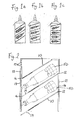
FR2940938 - A horsebox trailer of 2.5 m width is deemed too wide to be of practical use. Horsebox trailers frequently need to be taken down restricted routes, narrow lanes, driveways and narrow gate openings that are difficult to navigate with a 2.3 m wide trailer, let alone try with a 2.5 m wide trailer. Therefore, it is generally desirable, in respect of horseboxes, to provide a partition system that works at a trailer maximum width of 2.3 m but with minimum floor area to keep the trailer weight and size to an absolute minimum. It is also desirable to provide for adjustment of the number, position and spacing of partitions within the horsebox to accommodate different numbers of horses or ponies, from one or two adult horses up to three or four ponies. With a minimum stall length of 2.5 m for adult horses and a trailer width of only 2.3 m stalls for horses need to be positioned diagonally (obliquely) across the trailer to make best use of floor space. As ponies only require a stall length of 1.8 m they can be positioned transversely (perpendicularly) across the trailer. This uses less space and allows carriage of additional ponies in the space required for adult horses.
- To meet these requirements it is already known to provide stall partitions for horseboxes which can be mounted in either the transverse (i.e. perpendicular) or diagonal (i.e. oblique) positions. By way of example, three known arrangements which may be used for two adult horses, three juvenile horses (or three large ponies) or four small ponies, respectively, are shown in schematic plan view in accompanying
figures 1a, 1 b and 1c . - As illustrated in accompanying
figure 2 which is a schematic plan view of a known horsebox partitioning system, in existing horseboxes manufactured by the applicant and by others, thepartitions 10 defining the stalls for accommodatinganimals 50 are each pivotably connected at spacedlocations 12 along the interior of oneside wall 11 of the box. These pivotal connection locations 12 (other than the first one at the front) are appropriately selected by the user from any one of a series of connection points arranged, for example, about 10 cm apart along arail 14 mounted along the said side wall. Thepartitions 10 may then be arranged by being swung to take up appropriate positions either at an oblique angle or substantially perpendicular to the longitudinal axis of the box, whatever the user selects as being the most suitable orientation of partitions for the animals which are being transported. The free ends of thesepartitions 10 are attachable atsuitable locations 16 along the interior of theopposing side wall 13 of the box. Again, theattachment locations 16 are selected by the user from a series of attachment points provided byholes 17 arranged along asimilar rail 18 mounted along theopposing side wall 13 of the box. - As any
particular partition 10 is switched from the substantially perpendicular position to the oblique position it needs to increase in length. In the known arrangement this has been achieved by providing, on eachpartition 10, aconnection arm 19 in the form of a sliding telescopic tube that extends axially and substantially horizontally out of the free end of the partition to reach and be connected to theother side 13 of the box. This knowntelescopic attachment arm 19 is shown more clearly infigure 3 which is an enlarged perspective view showing how onepartition 10 is attached in an oblique disposition. The problem with such atelescopic tube 19 is that it becomes inherently weaker to bending as it is extended. To cope with the load of an adult horse standing in an obliquely oriented stall and leaning against the partition it becomes increasingly difficult to make theconnection arm 19 strong enough without making the partition as a whole too heavy. Also, as the length of the partition is increased only by the projection of the tubular arm a gap is created in the sides of the stalls (the space below the or each extended connection arm 19) which the horse may attempt to get through either to disturb the neighbouring horse, or to try and escape, or it may get trapped or injured in this way. - Additionally, as is apparent in
figure 2 , with theextended connection arm 19 in line with thepartition leaf 10, additional trailer length is required to make the connection when the partitions are arranged obliquely for adult horses, which results in a greater amount of wasted space at the opposing corners at each end of the box. -
AU 2005202792 A1 - An object of the invention is to provide an improved partitioning system which also obviates the above-discussed problems relating to changing partition arrangement while minimising the size of horsebox, specifically the length of the horsebox, required to accommodate the same number of animals as hitherto.
- A further object is to improve the fastening arrangement and provide other safety features.
- The present invention provides a partition for a horsebox comprising: a main leaf having a first end adapted for pivotable attachment to a side wall of a box enclosure and having a second end; an auxiliary leaf hingedly connected to the second end of the main leaf; a fixed length connection arm which is connected either to the main leaf or to the auxiliary leaf and which is swingable in a substantially horizontal plane; and a fastening device carried at the free end of the connection arm; characterised in that the fixed length connection arm is also hingedly connected, either to the main leaf or to the auxiliary leaf, so as to be swingable in a substantially vertical plane.
- The vertical pivoting capability of the connector arm makes for a better connection with great ease of making the connection and further possibilities for improved features. In preferred embodiments the connector arm extends side-by-side with the auxiliary leaf. This means that the sides of the stalls remain closed off by the auxiliary leaf irrespective of any increase in the partition length for oblique disposition of partitions. Moreover, the folding/swinging of the auxiliary leaf relative to the main leaf of the partition at the same time as the pivoting of the connection arm relative to the main leaf of the partition allows the partition as a whole to assume a disposition, apparent from accompanying
figure 4 . The connection arm and the auxiliary leaf can be folded back towards the side wall as shown, to make connection with the side wall attachment rail at a more forward position than with the known axially projecting telescopic tube (figure 2 ). This occupies less space longitudinally when the partitions are disposed obliquely compared to the known arrangement shown infigure 2 . Therefore with the present invention a shorter box length can be provided to accommodate the same number of horses/ponies. - In accordance with the invention the fixed length connection arm of the partition is also hingedly connected, either to the main leaf or to the auxiliary leaf, so as to be swingeable upwards and downwards, i.e. in a substantially vertical plane, as well as side to side. This has two main advantages. It allows the free end of the arm, which typically needs to project beyond the free end of the auxiliary leaf when making a connection with the opposing side wall of the box, to drop down out of harm's way when loading horses so neither human or animal risk injury from it. The up and down movement also allows the connection arm of the invention to carry a fastener in the form of a retainer pin which can hook into or engage from above into the hole in the opposing side wall rail when making the connection. Thus the arm can easily be lifted and then moved down to make the connection. This is far easier than the previous fastening arrangement (see
figure 3 ) where holes in aU-shaped jaw element 15 had to be lined up with therelevant hole 17 in therail 18 for insertion of a retainer pin through the aligned holes. Such ease of fastening is important as a horse may be pushing against the partition and moving around in the stall as an operator is in the process of attaching the connection arm to the box side wall. With the previous arrangement the alignment of holes could prove difficult under these circumstances. - Further features and advantages of the invention will become apparent from the following description. The invention will be described further, by way of example, with reference to the accompanying drawings, in which:
-
Figure 1a, 1b, 1c are schematic plan views shown known horsebox partitioning arrangements; -
Figure 2 is an enlarged plan view of another known horsebox partition arrangement with the partitions arranged obliquely relative to the direction of travel; -
Figure 3 is an enlarged perspective partial view showing the structure of the known partition as depicted infigure 2 ; -
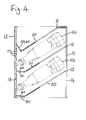
Figure 4 is a plan view of a horsebox provided with embodiments of partitions in accordance with the invention disposed in an oblique arrangement comparable to that infigure 2 ; -
Figure 5 is a plan view of the same horsebox as infigure 4 with the partitions of the invention disposed in an alternative transverse (substantially perpendicular to direction of travel) arrangement; -
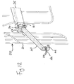
Figure 6 is a side view of an individual preferred practical embodiment of the partition of the invention; -
Figure 7 is the same asFigure 6 , but showing the connection arm in a part way lowered position; -
Figure 8 is an enlarged perspective partial view, comparable tofigure 3 , showing the partition offigure 6 as in use; -
Figure 9 is a schematic plan view diagram showing favourable and unfavourable configuration of a partition with a pivotal connection arm; -
Figure 10 is a perspective partial view to a yet larger scale showing a partially lowered condition of the connection arm of the partition ofFigures 6 and7 ; -
Figure 11 is a view similar tofigure 10 showing a partially raised condition of the connection arm; -
Figure 12 is a view taken from a different angle, closer to the outer end of the partition, showing the connection arm in a partially raised condition as inFigure 11 ; -
Figure 13 is a further enlarged detail of the connection arm lifting stop means with the arm in a partially raised position similar to that shown inFigures 11 and12 ; and -
Figure 14 is a similar enlarged detail of the connection arm stop means in a condition where the arm is prevented from being lifted. - With reference to
figures 4 to 8 and10 to 14 , a preferred practical embodiment of a horsebox partition in accordance with the present invention comprises a main leaf designated generally byreference numeral 20, anauxiliary leaf 30 hingedly connected at hinges 33, 34 to an outer end of themain leaf 20, and a fixedlength connection arm 40 which is connected to theauxiliary leaf 30 close to thehinge 34 at the outer end of themain leaf 20, and which carries afastener 42 at its free end. Theconnection arm 40 is swingable in a vertical plane aboutpivot pin 41. The structure of the partition as a whole is shown infigures 6 and7 . - The structure of the
main leaf 20 may vary in other embodiments. It is not relevant to the present innovation. As illustrated it comprises apanel 22 mounted in a framework of atubular post 23 at the inner end of themain leaf 20, an uppertubular cross bar 25 and a benttubular element 26. In use, theinner post 23 is pivotably connected at a location selected by the user along arail 14 provided along oneside wall 11 of a horse box, with typical positioning being shown infigures 4 and5 . Arubber skirt panel 27 typically hangs down from the lower part of thetubular element 26, while ahead height grille 29 is mounted above theupper cross bar 25 and connects to an upper section of theauxiliary leaf 30 by way of thehinge 33. - The
auxiliary leaf 30 is in the form of an open grille, having a bentouter frame element 31 and spacedvertical bars 32. It is hingedly connected at the upper and lower hinges 33, 34 to themain leaf 20 so as to swing side to side. It extends the length of thegrille 29 of themain leaf 20 and part of the height of thepanel 22. - The
connection arm 40 may be a hollow profile of square or polygonal cross section. It is connected to theauxiliary leaf 30 near thehinge point 34 so as to swing side to side in unison with and in generally parallel alignment with theauxiliary leaf 30. However, as already mentioned thearm 40 is additionally hingedly connected about ahorizontal pivot pin 41, adjacent with thehinge point 34, so as to be swingable up and down in a substantically vertical plane. - When the
connection arm 40 extends in a horizontal position as shown infigure 6 , it projects a short distance, in the region of 10cm, beyond the free edge of theauxiliary leaf 30. At its free end thefastener 42 is in the form of a downwardly extending frusto-conical tapering retainer pin on which two rubber O-rings 44 are preferably mounted, and a washer of plastics material may also be provided thereon closely adjacent the arm. This is best shown infigures 10 to 12 . Theretainer pin 42 has a transverse through passage into which alinchpin 46 can be inserted. Because theconnection arm 40 is pivotable in a vertical plane, about thepivot pin 41, it can be lifted to a position raised above horizontal, as shown infigures 11 and12 , to enable it easily to be dropped into engagement with any selectedhole 17 in therail 18. - This is how the free end of the partition is secured to the
side wall 13 of the box to form a stall. The O-rings 44 and optional washer are anti-rattle features which prevent direct metal to metal contact noise between thepin 42 andother rail 18. Thelinchpin 46 is pushed into position after theretainer pin 42 has been inserted and engaged in thehole 17 as the passage to receive thelinchpin 46 is then at a position below therail 18. - A
stop element 48 configured as a shallow U-shaped handle is provided on the side of theauxiliary leaf 30 adjacent thepivot pin 41. When theconnection arm 40 is not being lifted or is not in a substantially horizontal position when in use for attaching the partition to therail 18, it swings down to a sloping at rest position, as defined by its abutment against the stop element. In its lower, at rest position, abutting the stop element (seeFigure 7 ), the free end of theconnection arm 40 and theretainer pin 42 carried thereby, do not project beyond the free edge of theauxiliary leaf 30. This avoids any risk of injury to human or animal from a projecting element at this height. - Despite the considerable advantages in terms of space saving and versatility of partition arrangements by having a sideways pivoting auxiliary leaf and connection arm, as explained above with reference to
Figures 4 and5 , there is one potential problem which may arise. If a partition is positioned with theauxiliary leaf 30 and theconnection arm 40 substantially in alignment with themain leaf 20, or at only a shallow angle, e.g. of less than 45° relative to themain leaf 20, there is a risk that when a horse is confined in a compartment adjacent that partition it may push sideways against the partition with sufficient force to cause the box trailer sides either to deform and cause an angle to be created between the main and auxiliary leaves or to spring outwards and allow the angle between the auxiliary and main leaves to be reversed. This would result in the adjacent compartment being reduced in size. One horse may then have too much space, which is undesirable during transport, and another horse in the adjacent compartment may have too little space, also undesirable.Figure 9 illustrates the partition configurations which are favourable and unfavourable. -
Figures 10 to 14 illustrate an arrangement of anabutment 52 formed on anupper bracket 54 mounting thehinge 34 which acts as a stop to prevent theconnection arm 40 being lifted (by pivoting in a vertical plane about the pivot pin 41) when in a certain angular relationship to themain leaf 30. In this particular embodiment, theconnection arm 40 carries anupward projection 58 at its end adjacent thepivot pin 41 and theabutment 52 is of dovetail shape, thus blocking upward movement by contact of theprojection 58 with the abutment for an angle a of approximately 45° (seeFigure 13 ) either side of where theauxiliary leaf 30 andarm 40 are in line with the main leaf. In this way, because thearm 40 cannot be lifted to allow engagement of thefastener 40, thearm 40 cannot be connected to the other side of the box trailer container at an undesirable angular position relative to themain leaf 20. Obviously a different angular range and a different style of abutment and stop arrangement could be employed in other embodiments. - The overall manner of use of this preferred embodiment of the partition of the invention will be readily apparent from
figures 4 ,5 ,8 and10 to 14 of the drawings. Just as in the prior art horseboxes offigures 1, 2 and3 , theinner posts 23 of a chosen number of partitions are connected pivotably at selectedlocations 12 along arail 14 at a first side of the horse box interior. These locations are chosen for the appropriate spacing to form stalls of appropriate width and orientation for the number of horses, ponies or other animals which are to be transported. An example of an oblique arrangement of partitions providing stalls for two adult horses is shown infigure 4 . An example of a transverse arrangement, i.e. substantially perpendicular to direction of travel providing stalls for three smaller animals, such as ponies, is shown infigure 5 . - Initially, the partition closest to the front of the box in the direction of travel is fixed in position. The
auxiliary leaf 30 and theconnection arm 40 are folded to whatever angle is required to attach thefastener 42 to the selectedhole 17 on therail 18 along the opposingside wall 13 of the box, subject only to this not being permitted to be in line or 45° either side, because of theabutment 52. To make the connection, thearm 40 is raised and theretainer pin 42 is then fitted from above into the hole and secured by thelinchpin 46. The remaining pivotably connected partitions are swung into an inoperative position flat against thefirst side wall 11. The animals are then moved into the box one at a time from a door and ramp at the rear of the box. Once each animal is in its position the partition which completes its stall is deployed by being swung into position behind it. Again the respectiveauxiliary leaf 30 and theconnection arm 40 are folded to whatever angle is required to attach therespective fastener 42 to the selected position ofhole 17 on the rail along theother side 13 of the box, subject only to this not being permitted to be in line or 45° either side, because of theabutment 52. - Comparing
figure 4 with the prior art arrangement shown infigure 2 it will be seen that the pivotable folding of theauxiliary leaf 30 and theconnection arm 40 allows these to be folded back so as to connect to the opposite side wall of the box in a more forward position than was possible with the prior art, where the connection arm extended in line with the panel. Thus the length of the box or trailer can be shorter and still accommodate the same number of animals, with less wasted space at the corners of the enclosure. - The invention is not restricted to the details of the foregoing embodiments and many variations are possible within the scope of the appended claims as will be apparent to a skilled person. In particular, in other embodiments, possibly less favourable, the fastener on the connection arm may take another form from the illustrated embodiment. It need not be tapered, nor even have a tapered portion and could be straight. With the illustrated type of fastener or similar, the linchpin could be replaced by any other suitable type of clip or pin. The connection arm may be hingedly attached to the main leaf instead of to the auxiliary leaf of the partition, or by the effective common hinge as in the illustrated embodiment. The auxiliary leaf could be in the form of a solid sheet, for example of plywood or plastics material, instead of being in the form of an open grill, as in the illustrated version. Many other alternatives to the configuration and material of the individual components are possible as already mentioned.
- Throughout the description and claims of this specification, the words "comprise" and "contain" and variations of them mean "including but not limited to", and they are not intended to (and do not) exclude other components. Throughout the description and claims of this specification, the singular encompasses the plural unless the context otherwise requires. Features described in conjunction with a particular embodiment or example of the invention are to be understood to be applicable to any other embodiment or example unless incompatible therewith.
Claims (15)
- A partition for a horsebox comprising:a main leaf (20) having a first end (23) adapted for pivotable attachment to a side wall (11) of a box enclosure and having a second end; an auxiliary leaf (30) hingedly connected to the second end of the main leaf (20); a fixed length connection arm (40) which is connected either to the main leaf (20) or to the auxiliary leaf (30) and which is swingable in a substantially horizontal plane; and a fastening device (42) carried at the free end of the connection arm (40); characterised in that the fixed length connection arm (40) is also hingedly connected, either to the main leaf (20) or to the auxiliary leaf (30), so as to be swingable in a substantially vertical plane.
- A partition for a horsebox according to claim 1 wherein the fixed length connection arm (40) is hingedly connected to the second end of the auxiliary leaf (30).
- A partition for a horsebox according to claim 1 wherein the fixed length connection arm (40) is connected to the auxiliary leaf (30) so as to swing side to side in unison with the auxiliary arm.
- A partition for a horsebox according to claim 1 wherein the fixed length connection arm (40) is hingedly connected to the second end of the main leaf (20).
- A partition for a horsebox according to claim 4 wherein the fixed length connection arm (40) and the auxiliary leaf (30) of the partition are mounted to a common, substantially vertical hinge (34) so as to swing side to side in unison.
- A partition for a horsebox according to any preceding claim wherein the fixed length connection arm (40) has a lower at rest position wherein it does not project outwards beyond the free end of the auxiliary leaf (30) of the partition.
- A partition for a horsebox according to any preceding claim wherein a stop element (48) is provided to define the lower at rest position of the fixed length connection arm (40).
- A partition for a horsebox according to claim 7 wherein the stop element (48) defines the lower at rest position of the fixed length connection arm (40) to be at an angle sloping downward from its hinged connection at an angle between horizontal and vertical.
- A partition for a horsebox according to any preceding claim wherein the auxiliary leaf (30) is in the form of an outer frame (31) with upright crosspieces (32) mounted therein.
- A partition for a horsebox according to any preceding claim wherein the fastening means (42) is a downwardly projecting retainer pin mounted at the free end of the fixed length connection arm (40) for engagement into a hole (17) in a standard side wall rail (18) of a horsebox.
- A partition for a horsebox according to claim 10 wherein the retainer pin (42) is tapered.
- A partition for a horsebox according to claim 10 or 11 wherein the retainer pin (42) is provided with at least one O-ring (44) or other annular resilient element.
- A partition for a horsebox according to any of claims 10 to 12, where the retainer pin (42) is provided with a transverse through passage for engagement of a linchpin (46).
- A partition for a horsebox according to any of claims 10 to 13 wherein an abutment (52) is provided to prevent upward movement of the fixed length connection arm (40) when the arm is in co-planar alignment with the main leaf (20) and in a predetermined angular range each side of such co-planar alignment.
- A horsebox provided with at least one partition as defined in any preceding claim.
Applications Claiming Priority (2)
| Application Number | Priority Date | Filing Date | Title |
|---|---|---|---|
| GBGB1310519.2A GB201310519D0 (en) | 2013-06-13 | 2013-06-13 | Horsebox partition |
| GB1409414.8A GB2517826B (en) | 2013-06-13 | 2014-05-28 | Horsebox partition |
Publications (3)
| Publication Number | Publication Date |
|---|---|
| EP2813393A2 true EP2813393A2 (en) | 2014-12-17 |
| EP2813393A3 EP2813393A3 (en) | 2015-11-11 |
| EP2813393B1 EP2813393B1 (en) | 2019-10-30 |
Family
ID=48876199
Family Applications (1)
| Application Number | Title | Priority Date | Filing Date |
|---|---|---|---|
| EP14172155.5A Active EP2813393B1 (en) | 2013-06-13 | 2014-06-12 | Horsebox partition |
Country Status (2)
| Country | Link |
|---|---|
| EP (1) | EP2813393B1 (en) |
| GB (2) | GB201310519D0 (en) |
Family Cites Families (5)
| Publication number | Priority date | Publication date | Assignee | Title |
|---|---|---|---|---|
| US382934A (en) * | 1888-05-15 | Stock-car | ||
| US340946A (en) * | 1886-04-27 | Stock-car | ||
| US3413932A (en) * | 1966-10-03 | 1968-12-03 | Evans Prod Co | Bulkhead |
| US7040253B1 (en) * | 2003-04-18 | 2006-05-09 | Universal Trailer Corporation Horse?Livestock Group | Horse trailer interior partition latching system |
| AU2005202792A1 (en) * | 2004-06-25 | 2006-01-12 | David Writer | Chestbar for angleload horsefloats |
-
2013
- 2013-06-13 GB GBGB1310519.2A patent/GB201310519D0/en not_active Ceased
-
2014
- 2014-05-28 GB GB1409414.8A patent/GB2517826B/en active Active
- 2014-06-12 EP EP14172155.5A patent/EP2813393B1/en active Active
Also Published As
| Publication number | Publication date |
|---|---|
| GB2517826A (en) | 2015-03-04 |
| GB201409414D0 (en) | 2014-07-09 |
| GB2517826B (en) | 2015-08-26 |
| GB201310519D0 (en) | 2013-07-24 |
| EP2813393B1 (en) | 2019-10-30 |
| EP2813393A3 (en) | 2015-11-11 |
Similar Documents
| Publication | Publication Date | Title |
|---|---|---|
| US5170746A (en) | Portable livestock pen | |
| US8534734B2 (en) | Animal barrier for vehicles | |
| US5628540A (en) | Pickup truck utility rack | |
| CA2813224C (en) | Vehicular storage system | |
| US8910593B2 (en) | Livestock trailer corral assembly | |
| US4870984A (en) | Portable shelter with wind break | |
| US6450124B1 (en) | Portable corral | |
| US8312846B1 (en) | Animal loading/unloading apparatus | |
| US4366775A (en) | Transportable stock unit | |
| US4824157A (en) | Utility cage for vehicles | |
| US8328266B2 (en) | Pick-up style utility vehicle with expandable cargo bed | |
| US20080185860A1 (en) | Retractable enclosure for small land vehicle | |
| US7740430B2 (en) | Support assembly for use with truck bed | |
| US20120298678A1 (en) | Vehicle modular storage system | |
| US3475046A (en) | Adjustable rack bodies for pickup trucks | |
| KR200482911Y1 (en) | Cover structure of deck for vehicle | |
| EP2813393B1 (en) | Horsebox partition | |
| US7160071B2 (en) | Truck bed divider apparatus | |
| US20050224011A1 (en) | Portable calf pen and method of use | |
| KR101934925B1 (en) | Camping trailer for vehicle | |
| US20030193210A1 (en) | Mounting assembly for a truck bed cover | |
| US20080122238A1 (en) | Truck bed animal enclosure device | |
| US20120299338A1 (en) | Vehicle jump seat and storage system | |
| US9388630B1 (en) | Window blind protector | |
| EP3476212A1 (en) | Car entry aid for dogs |
Legal Events
| Date | Code | Title | Description |
|---|---|---|---|
| 17P | Request for examination filed |
Effective date: 20140612 |
|
| AK | Designated contracting states |
Kind code of ref document: A2 Designated state(s): AL AT BE BG CH CY CZ DE DK EE ES FI FR GB GR HR HU IE IS IT LI LT LU LV MC MK MT NL NO PL PT RO RS SE SI SK SM TR |
|
| AX | Request for extension of the european patent |
Extension state: BA ME |
|
| PUAI | Public reference made under article 153(3) epc to a published international application that has entered the european phase |
Free format text: ORIGINAL CODE: 0009012 |
|
| PUAL | Search report despatched |
Free format text: ORIGINAL CODE: 0009013 |
|
| AK | Designated contracting states |
Kind code of ref document: A3 Designated state(s): AL AT BE BG CH CY CZ DE DK EE ES FI FR GB GR HR HU IE IS IT LI LT LU LV MC MK MT NL NO PL PT RO RS SE SI SK SM TR |
|
| AX | Request for extension of the european patent |
Extension state: BA ME |
|
| RIC1 | Information provided on ipc code assigned before grant |
Ipc: B60P 3/04 20060101AFI20151008BHEP |
|
| R17P | Request for examination filed (corrected) |
Effective date: 20151202 |
|
| RBV | Designated contracting states (corrected) |
Designated state(s): AL AT BE BG CH CY CZ DE DK EE ES FI FR GB GR HR HU IE IS IT LI LT LU LV MC MK MT NL NO PL PT RO RS SE SI SK SM TR |
|
| GRAP | Despatch of communication of intention to grant a patent |
Free format text: ORIGINAL CODE: EPIDOSNIGR1 |
|
| STAA | Information on the status of an ep patent application or granted ep patent |
Free format text: STATUS: GRANT OF PATENT IS INTENDED |
|
| INTG | Intention to grant announced |
Effective date: 20190628 |
|
| GRAS | Grant fee paid |
Free format text: ORIGINAL CODE: EPIDOSNIGR3 |
|
| GRAA | (expected) grant |
Free format text: ORIGINAL CODE: 0009210 |
|
| STAA | Information on the status of an ep patent application or granted ep patent |
Free format text: STATUS: THE PATENT HAS BEEN GRANTED |
|
| AK | Designated contracting states |
Kind code of ref document: B1 Designated state(s): AL AT BE BG CH CY CZ DE DK EE ES FI FR GB GR HR HU IE IS IT LI LT LU LV MC MK MT NL NO PL PT RO RS SE SI SK SM TR |
|
| REG | Reference to a national code |
Ref country code: GB Ref legal event code: FG4D |
|
| REG | Reference to a national code |
Ref country code: CH Ref legal event code: EP |
|
| REG | Reference to a national code |
Ref country code: AT Ref legal event code: REF Ref document number: 1195772 Country of ref document: AT Kind code of ref document: T Effective date: 20191115 |
|
| REG | Reference to a national code |
Ref country code: DE Ref legal event code: R096 Ref document number: 602014055840 Country of ref document: DE |
|
| REG | Reference to a national code |
Ref country code: IE Ref legal event code: FG4D |
|
| REG | Reference to a national code |
Ref country code: LT Ref legal event code: MG4D |
|
| PG25 | Lapsed in a contracting state [announced via postgrant information from national office to epo] |
Ref country code: PT Free format text: LAPSE BECAUSE OF FAILURE TO SUBMIT A TRANSLATION OF THE DESCRIPTION OR TO PAY THE FEE WITHIN THE PRESCRIBED TIME-LIMIT Effective date: 20200302 Ref country code: BG Free format text: LAPSE BECAUSE OF FAILURE TO SUBMIT A TRANSLATION OF THE DESCRIPTION OR TO PAY THE FEE WITHIN THE PRESCRIBED TIME-LIMIT Effective date: 20200130 Ref country code: FI Free format text: LAPSE BECAUSE OF FAILURE TO SUBMIT A TRANSLATION OF THE DESCRIPTION OR TO PAY THE FEE WITHIN THE PRESCRIBED TIME-LIMIT Effective date: 20191030 Ref country code: NL Free format text: LAPSE BECAUSE OF FAILURE TO SUBMIT A TRANSLATION OF THE DESCRIPTION OR TO PAY THE FEE WITHIN THE PRESCRIBED TIME-LIMIT Effective date: 20191030 Ref country code: SE Free format text: LAPSE BECAUSE OF FAILURE TO SUBMIT A TRANSLATION OF THE DESCRIPTION OR TO PAY THE FEE WITHIN THE PRESCRIBED TIME-LIMIT Effective date: 20191030 Ref country code: LV Free format text: LAPSE BECAUSE OF FAILURE TO SUBMIT A TRANSLATION OF THE DESCRIPTION OR TO PAY THE FEE WITHIN THE PRESCRIBED TIME-LIMIT Effective date: 20191030 Ref country code: LT Free format text: LAPSE BECAUSE OF FAILURE TO SUBMIT A TRANSLATION OF THE DESCRIPTION OR TO PAY THE FEE WITHIN THE PRESCRIBED TIME-LIMIT Effective date: 20191030 Ref country code: PL Free format text: LAPSE BECAUSE OF FAILURE TO SUBMIT A TRANSLATION OF THE DESCRIPTION OR TO PAY THE FEE WITHIN THE PRESCRIBED TIME-LIMIT Effective date: 20191030 Ref country code: GR Free format text: LAPSE BECAUSE OF FAILURE TO SUBMIT A TRANSLATION OF THE DESCRIPTION OR TO PAY THE FEE WITHIN THE PRESCRIBED TIME-LIMIT Effective date: 20200131 Ref country code: NO Free format text: LAPSE BECAUSE OF FAILURE TO SUBMIT A TRANSLATION OF THE DESCRIPTION OR TO PAY THE FEE WITHIN THE PRESCRIBED TIME-LIMIT Effective date: 20200130 Ref country code: ES Free format text: LAPSE BECAUSE OF FAILURE TO SUBMIT A TRANSLATION OF THE DESCRIPTION OR TO PAY THE FEE WITHIN THE PRESCRIBED TIME-LIMIT Effective date: 20191030 |
|
| REG | Reference to a national code |
Ref country code: NL Ref legal event code: MP Effective date: 20191030 |
|
| PG25 | Lapsed in a contracting state [announced via postgrant information from national office to epo] |
Ref country code: HR Free format text: LAPSE BECAUSE OF FAILURE TO SUBMIT A TRANSLATION OF THE DESCRIPTION OR TO PAY THE FEE WITHIN THE PRESCRIBED TIME-LIMIT Effective date: 20191030 Ref country code: IS Free format text: LAPSE BECAUSE OF FAILURE TO SUBMIT A TRANSLATION OF THE DESCRIPTION OR TO PAY THE FEE WITHIN THE PRESCRIBED TIME-LIMIT Effective date: 20200229 Ref country code: RS Free format text: LAPSE BECAUSE OF FAILURE TO SUBMIT A TRANSLATION OF THE DESCRIPTION OR TO PAY THE FEE WITHIN THE PRESCRIBED TIME-LIMIT Effective date: 20191030 |
|
| PG25 | Lapsed in a contracting state [announced via postgrant information from national office to epo] |
Ref country code: AL Free format text: LAPSE BECAUSE OF FAILURE TO SUBMIT A TRANSLATION OF THE DESCRIPTION OR TO PAY THE FEE WITHIN THE PRESCRIBED TIME-LIMIT Effective date: 20191030 |
|
| PG25 | Lapsed in a contracting state [announced via postgrant information from national office to epo] |
Ref country code: RO Free format text: LAPSE BECAUSE OF FAILURE TO SUBMIT A TRANSLATION OF THE DESCRIPTION OR TO PAY THE FEE WITHIN THE PRESCRIBED TIME-LIMIT Effective date: 20191030 Ref country code: CZ Free format text: LAPSE BECAUSE OF FAILURE TO SUBMIT A TRANSLATION OF THE DESCRIPTION OR TO PAY THE FEE WITHIN THE PRESCRIBED TIME-LIMIT Effective date: 20191030 Ref country code: DK Free format text: LAPSE BECAUSE OF FAILURE TO SUBMIT A TRANSLATION OF THE DESCRIPTION OR TO PAY THE FEE WITHIN THE PRESCRIBED TIME-LIMIT Effective date: 20191030 Ref country code: EE Free format text: LAPSE BECAUSE OF FAILURE TO SUBMIT A TRANSLATION OF THE DESCRIPTION OR TO PAY THE FEE WITHIN THE PRESCRIBED TIME-LIMIT Effective date: 20191030 |
|
| REG | Reference to a national code |
Ref country code: DE Ref legal event code: R097 Ref document number: 602014055840 Country of ref document: DE |
|
| REG | Reference to a national code |
Ref country code: AT Ref legal event code: MK05 Ref document number: 1195772 Country of ref document: AT Kind code of ref document: T Effective date: 20191030 |
|
| PG25 | Lapsed in a contracting state [announced via postgrant information from national office to epo] |
Ref country code: SK Free format text: LAPSE BECAUSE OF FAILURE TO SUBMIT A TRANSLATION OF THE DESCRIPTION OR TO PAY THE FEE WITHIN THE PRESCRIBED TIME-LIMIT Effective date: 20191030 Ref country code: IT Free format text: LAPSE BECAUSE OF FAILURE TO SUBMIT A TRANSLATION OF THE DESCRIPTION OR TO PAY THE FEE WITHIN THE PRESCRIBED TIME-LIMIT Effective date: 20191030 Ref country code: SM Free format text: LAPSE BECAUSE OF FAILURE TO SUBMIT A TRANSLATION OF THE DESCRIPTION OR TO PAY THE FEE WITHIN THE PRESCRIBED TIME-LIMIT Effective date: 20191030 |
|
| PLBE | No opposition filed within time limit |
Free format text: ORIGINAL CODE: 0009261 |
|
| STAA | Information on the status of an ep patent application or granted ep patent |
Free format text: STATUS: NO OPPOSITION FILED WITHIN TIME LIMIT |
|
| 26N | No opposition filed |
Effective date: 20200731 |
|
| PG25 | Lapsed in a contracting state [announced via postgrant information from national office to epo] |
Ref country code: SI Free format text: LAPSE BECAUSE OF FAILURE TO SUBMIT A TRANSLATION OF THE DESCRIPTION OR TO PAY THE FEE WITHIN THE PRESCRIBED TIME-LIMIT Effective date: 20191030 Ref country code: AT Free format text: LAPSE BECAUSE OF FAILURE TO SUBMIT A TRANSLATION OF THE DESCRIPTION OR TO PAY THE FEE WITHIN THE PRESCRIBED TIME-LIMIT Effective date: 20191030 |
|
| REG | Reference to a national code |
Ref country code: DE Ref legal event code: R119 Ref document number: 602014055840 Country of ref document: DE |
|
| PG25 | Lapsed in a contracting state [announced via postgrant information from national office to epo] |
Ref country code: MC Free format text: LAPSE BECAUSE OF FAILURE TO SUBMIT A TRANSLATION OF THE DESCRIPTION OR TO PAY THE FEE WITHIN THE PRESCRIBED TIME-LIMIT Effective date: 20191030 |
|
| REG | Reference to a national code |
Ref country code: CH Ref legal event code: PL |
|
| PG25 | Lapsed in a contracting state [announced via postgrant information from national office to epo] |
Ref country code: LU Free format text: LAPSE BECAUSE OF NON-PAYMENT OF DUE FEES Effective date: 20200612 |
|
| REG | Reference to a national code |
Ref country code: BE Ref legal event code: MM Effective date: 20200630 |
|
| PG25 | Lapsed in a contracting state [announced via postgrant information from national office to epo] |
Ref country code: CH Free format text: LAPSE BECAUSE OF NON-PAYMENT OF DUE FEES Effective date: 20200630 Ref country code: LI Free format text: LAPSE BECAUSE OF NON-PAYMENT OF DUE FEES Effective date: 20200630 Ref country code: IE Free format text: LAPSE BECAUSE OF NON-PAYMENT OF DUE FEES Effective date: 20200612 Ref country code: FR Free format text: LAPSE BECAUSE OF NON-PAYMENT OF DUE FEES Effective date: 20200630 |
|
| PG25 | Lapsed in a contracting state [announced via postgrant information from national office to epo] |
Ref country code: DE Free format text: LAPSE BECAUSE OF NON-PAYMENT OF DUE FEES Effective date: 20210101 Ref country code: BE Free format text: LAPSE BECAUSE OF NON-PAYMENT OF DUE FEES Effective date: 20200630 |
|
| PG25 | Lapsed in a contracting state [announced via postgrant information from national office to epo] |
Ref country code: TR Free format text: LAPSE BECAUSE OF FAILURE TO SUBMIT A TRANSLATION OF THE DESCRIPTION OR TO PAY THE FEE WITHIN THE PRESCRIBED TIME-LIMIT Effective date: 20191030 Ref country code: MT Free format text: LAPSE BECAUSE OF FAILURE TO SUBMIT A TRANSLATION OF THE DESCRIPTION OR TO PAY THE FEE WITHIN THE PRESCRIBED TIME-LIMIT Effective date: 20191030 Ref country code: CY Free format text: LAPSE BECAUSE OF FAILURE TO SUBMIT A TRANSLATION OF THE DESCRIPTION OR TO PAY THE FEE WITHIN THE PRESCRIBED TIME-LIMIT Effective date: 20191030 |
|
| PG25 | Lapsed in a contracting state [announced via postgrant information from national office to epo] |
Ref country code: MK Free format text: LAPSE BECAUSE OF FAILURE TO SUBMIT A TRANSLATION OF THE DESCRIPTION OR TO PAY THE FEE WITHIN THE PRESCRIBED TIME-LIMIT Effective date: 20191030 |
|
| PGFP | Annual fee paid to national office [announced via postgrant information from national office to epo] |
Ref country code: GB Payment date: 20250530 Year of fee payment: 12 |