EP2811343A1 - Control apparatus, control method, and storage medium - Google Patents
Control apparatus, control method, and storage medium Download PDFInfo
- Publication number
- EP2811343A1 EP2811343A1 EP14170479.1A EP14170479A EP2811343A1 EP 2811343 A1 EP2811343 A1 EP 2811343A1 EP 14170479 A EP14170479 A EP 14170479A EP 2811343 A1 EP2811343 A1 EP 2811343A1
- Authority
- EP
- European Patent Office
- Prior art keywords
- job
- shift
- copy
- discharge position
- copies
- Prior art date
- Legal status (The legal status is an assumption and is not a legal conclusion. Google has not performed a legal analysis and makes no representation as to the accuracy of the status listed.)
- Withdrawn
Links
Images












Classifications
-
- B—PERFORMING OPERATIONS; TRANSPORTING
- B65—CONVEYING; PACKING; STORING; HANDLING THIN OR FILAMENTARY MATERIAL
- B65H—HANDLING THIN OR FILAMENTARY MATERIAL, e.g. SHEETS, WEBS, CABLES
- B65H33/00—Forming counted batches in delivery pile or stream of articles
- B65H33/06—Forming counted batches in delivery pile or stream of articles by displacing articles to define batches
- B65H33/08—Displacing whole batches, e.g. forming stepped piles
-
- B—PERFORMING OPERATIONS; TRANSPORTING
- B65—CONVEYING; PACKING; STORING; HANDLING THIN OR FILAMENTARY MATERIAL
- B65H—HANDLING THIN OR FILAMENTARY MATERIAL, e.g. SHEETS, WEBS, CABLES
- B65H43/00—Use of control, checking, or safety devices, e.g. automatic devices comprising an element for sensing a variable
-
- G—PHYSICS
- G03—PHOTOGRAPHY; CINEMATOGRAPHY; ANALOGOUS TECHNIQUES USING WAVES OTHER THAN OPTICAL WAVES; ELECTROGRAPHY; HOLOGRAPHY
- G03G—ELECTROGRAPHY; ELECTROPHOTOGRAPHY; MAGNETOGRAPHY
- G03G15/00—Apparatus for electrographic processes using a charge pattern
- G03G15/65—Apparatus which relate to the handling of copy material
- G03G15/6538—Devices for collating sheet copy material, e.g. sorters, control, copies in staples form
- G03G15/6547—Shifting sets of sheets in the discharge tray
-
- B—PERFORMING OPERATIONS; TRANSPORTING
- B65—CONVEYING; PACKING; STORING; HANDLING THIN OR FILAMENTARY MATERIAL
- B65H—HANDLING THIN OR FILAMENTARY MATERIAL, e.g. SHEETS, WEBS, CABLES
- B65H2301/00—Handling processes for sheets or webs
- B65H2301/40—Type of handling process
- B65H2301/42—Piling, depiling, handling piles
- B65H2301/421—Forming a pile
- B65H2301/4212—Forming a pile of articles substantially horizontal
-
- B—PERFORMING OPERATIONS; TRANSPORTING
- B65—CONVEYING; PACKING; STORING; HANDLING THIN OR FILAMENTARY MATERIAL
- B65H—HANDLING THIN OR FILAMENTARY MATERIAL, e.g. SHEETS, WEBS, CABLES
- B65H2301/00—Handling processes for sheets or webs
- B65H2301/40—Type of handling process
- B65H2301/42—Piling, depiling, handling piles
- B65H2301/421—Forming a pile
- B65H2301/4219—Forming a pile forming a pile in which articles are offset from each other, e.g. forming stepped pile
-
- B—PERFORMING OPERATIONS; TRANSPORTING
- B65—CONVEYING; PACKING; STORING; HANDLING THIN OR FILAMENTARY MATERIAL
- B65H—HANDLING THIN OR FILAMENTARY MATERIAL, e.g. SHEETS, WEBS, CABLES
- B65H2511/00—Dimensions; Position; Numbers; Identification; Occurrences
- B65H2511/20—Location in space
-
- B—PERFORMING OPERATIONS; TRANSPORTING
- B65—CONVEYING; PACKING; STORING; HANDLING THIN OR FILAMENTARY MATERIAL
- B65H—HANDLING THIN OR FILAMENTARY MATERIAL, e.g. SHEETS, WEBS, CABLES
- B65H2511/00—Dimensions; Position; Numbers; Identification; Occurrences
- B65H2511/40—Identification
- B65H2511/417—Identification of state of the machine
-
- G—PHYSICS
- G03—PHOTOGRAPHY; CINEMATOGRAPHY; ANALOGOUS TECHNIQUES USING WAVES OTHER THAN OPTICAL WAVES; ELECTROGRAPHY; HOLOGRAPHY
- G03G—ELECTROGRAPHY; ELECTROPHOTOGRAPHY; MAGNETOGRAPHY
- G03G2215/00—Apparatus for electrophotographic processes
- G03G2215/00362—Apparatus for electrophotographic processes relating to the copy medium handling
- G03G2215/00886—Sorting or discharging
- G03G2215/0089—Shifting jobs
Definitions
- the present invention relates to control apparatuses, control methods, and storage media that control the discharge position of a sheet.
- a shift function that places output paper (printed material) at the same discharge destination (tray) while changing the discharge position (position in said tray) of the output paper is known.
- This shift function to shift the discharge position of printed material from print job to print job and to stack the shifted printed material makes it possible to distinguish the printed material that corresponds to a given print job with ease (this will be referred to as “job-to-job shifting” hereinafter).
- the discharge position is limited to two positions, namely a shifted position and an unshifted position, and thus printed materials discharged to the same discharge destination cannot be distinguished from each other based on the print job and based on individual copies within that print job at the same time.
- the present invention enables the realization of a technique that enables job-to-job shift and copy-to-copy shift to be distinguished from each other.
- FIG. 1 is a cross-sectional view illustrating an example of the configuration of an image forming apparatus according to an embodiment of the present invention.
- a printing apparatus 100 will be described here as an example of the image forming apparatus.
- the printing apparatus 100 includes an image forming section 101, a fixing section 102, a scanner section 103, a console section 104, a paper discharge section 107, a toner supply section 110, and an external sheet feed section 118.
- Sheet feed units 105 and 106, a conveyance unit 108, a primary transfer unit 111, a transfer belt 112, and a secondary transfer unit 113 are provided in the image forming unit 101.
- a switchback unit 109, a waste toner holding unit 114, fixing units 115 and 116, and conveyance units 117 and 123 are provided in the fixing section 102.
- a conveyance unit 119 and sheet feed units 120, 121, and 122 are provided in the external sheet feed section 118.
- the scanner section 103 optically reads an original document and generates electronic data representing an image of that document.
- the console section 104 accepts various types of instructions for the printing apparatus 100 made by an operator.
- the console section 104 is provided with a display unit having touch panel functionality along with physical keys.
- the sheet feed units 105, 106, 120, 121, and 122 hold paper (recording material) to be printed onto by the printing apparatus 100.
- the paper discharge section 107 discharges the paper printed onto by the printing apparatus 100 to the exterior of the printing apparatus 100.
- 124 indicates a shift mechanism unit, which is a mechanism unit for realizing a shift function, described later.
- rollers for conveying the paper are provided at set intervals.
- the switchback unit 109 inverts the output surface of the paper when the paper is discharged to the paper discharge section 107.
- the toner supply section 110 supplies toner, serving as a developer, to the image forming section 101.
- the primary transfer unit 111 transfers a toner image formed based on image data onto the transfer belt 112.
- the secondary transfer unit 113 transfers the toner image, transferred onto the transfer belt 112, onto paper.
- the waste toner holding unit 114 holds excess toner resulting from the transfer process.
- the fixing unit 115 fixes the toner onto the paper by applying heat and pressure to the paper onto which the image has been transferred by the secondary transfer unit 113.
- the fixing unit 116 reinforces the fix of the image by applying further heat and pressure to the paper onto which the image has been fixed by the fixing unit 115.
- the conveyance units 108, 119, and 123 form a conveyance path for conveying the paper.
- the conveyance unit 117 forms a conveyance path for conveying the paper from the fixing unit 115 to the fixing unit 116.
- the conveyance unit 123 forms a conveyance path for conveying the paper from the fixing unit 115 to the paper discharge section 107 or the switchback unit 109 without passing through the fixing unit 116.
- the conveyance units 108 and 119 form a conveyance path for feeding the paper from the sheet feed units 105 and 106 to the printing apparatus 100.
- FIG. 2 is a block diagram illustrating the configuration of a main controller 201 in the printing apparatus 100 according to the present embodiment.
- the main controller 201 includes a CPU 205, a RAM 206, a console unit I/F 207, a network I/F 208, a modem 209, a ROM 210, and an HDD 211. These elements are connected via an image bus I/F 213 to an image bus 224 that connects a CPU bus 212, an RIP I/F 214, a data compression unit 215, a device I/F 216, and an image processing unit 217.
- a network cable 203 for connecting to an external device via a network is connected to the network I/F 208.
- a line cable 204 for connecting to an external device over a telephone line is connected to the modem 209.
- the CPU 205 runs programs for controlling the main controller 201 as a whole.
- the RAM 206 is managed by a program run by the CPU 205.
- the RAM 206 is used as a receiving buffer for temporarily holding data received from the exterior, as an image memory for temporarily holding image data rasterized by a RIP 221, and so on.
- the ROM 210 stores programs run by the CPU 205, data, and so on.
- the HDD 211 is a non-volatile storage device capable of saving various types of data for long periods of time.
- the console unit I/F 207 is an interface for connecting the console section 104 and the main controller 201.
- the RIP 221 is connected to the RIP I/F 214 via a data bus 218.
- the RIP 221 is a raster image processor having functionality for converting image format data input from the exterior into bitmap image data.
- the RIP I/F 214 is an interface for connecting the RIP 221 and the image bus 224 via the data bus 218.
- the data compression unit 215 compresses data.
- a paper feed/discharge unit 222 is connected to the device I/F 216 via a data bus 219, and a printer 223 is connected to the device I/F 216 via a data bus 220.
- the configuration of the printer 223 is as described above using FIG. 1 .
- the CPU 205 issues commands for printing to the printer 223 and the paper feed/discharge unit 222 via the data buses 219 and 220 in accordance with signals supplied from the console section 104, an external device via the network cable 203, or the like.
- the CPU 205 also issues commands specifying discharge processes such as shifting, punching, and so on to a control apparatus included in the paper feed/discharge unit 222, based on the paper printed onto.
- the image processing unit 217 executes various types of image processes on the bitmap image data generated by the RIP 221.
- the image processing unit 217 includes a function for processing the bitmap image data digitally, such as a function for combining two pages' worth of bitmap image data into a single page's worth of bitmap image data.
- a job control unit 225 analyzes data received from the exterior as a job, obtains control information such as a number of copies (a copy number; N), a paper feed designation, discharge processing information (shifting, stapling, a discharge destination), and so on, and controls the data as part of the job.
- a job control information storage unit 226 is a region for storing the obtained control information.
- a paper feed control unit 227 performs control related to paper feeding along with the CPU 205 and the job control unit 225.
- a discharge control unit 228 performs control related to paper discharge, on a paper-by-paper basis, along with the CPU 205 and the job control unit 225. In particular, the discharge control unit 228 issues discharge processing commands indicating processing to be performed in relation to the discharge control information, on a print paper-by-print paper basis, and manages the stated processing.
- a shift control unit 229 performs specialized control for the shift function along with the CPU 205, the job control unit 225, and the discharge control unit 228.
- a shift control information storage unit 230 holds control information necessary for managing the shift control unit 229.
- a device state monitoring unit 231 monitors states of the printing apparatus 100 that arise during printing, along with the CPU 205 and the job control unit 225.
- the shift function is a function in which printed paper (sheets on which images have been formed) are placed in the same discharge location but are slid (shifted) by a predetermined amount (an offset value) in a direction orthogonal to a direction in which the paper is discharged.
- a predetermined amount an offset value
- a plurality (at least four) offset values are provided, and the paper is shifted and discharged to at least four different positions.
- the shift mechanism unit 124 can shift the discharge direction of the paper by a predetermined amount in the direction orthogonal to the discharge direction of the paper by sliding a discharge roller 125, driven by a motor (not shown), in the direction orthogonal to the discharge direction of the paper.
- the offset values that determine the predetermined amounts are managed by a shift setting information holding table (see FIG. 5A ), which is held in the shift control information storage unit 230 and will be described later.
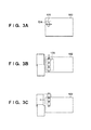
- FIG. 3A is a side view of the fixing section 102
- FIG. 3B is a top view of the fixing section 102
- FIG. 3C illustrates a state in which the discharge roller 125 has been shifted upward relative to the state shown in FIG. 3B
- the discharge roller 125 is structured to be capable of sliding to the left and right of (in the direction orthogonal to) the conveyance direction of the paper.
- the discharge roller 125 is moved to a position centered on the conveyance path (an offset of 0; a shift position number 0) ( FIG. 3B ).
- the discharge roller 125 After the discharge roller 125 has received the paper, the discharge roller 125 is shifted by the offset amount corresponding to the current shift position number in the shift position management table ( FIG. 5B ), for each piece of paper that is conveyed.
- the paper can be discharged while shifting the position of the paper in the direction orthogonal to the conveyance direction by sliding the discharge roller 125 by a predetermined amount (the offset value) to the left or right relative to the direction in which the paper advances and discharging the paper.
- FIG. 4 is a diagram illustrating an example of the result of discharging paper shifted according to the shift position management table ( FIG. 5B ) according to the embodiment.
- 400 indicates a discharge position in the case where the offset amount is 0. Discharge positions whose offset amounts are X, 2X, -X, and -2X relative to the offset amount of 0 are also indicated.
- the shift position management table shown in FIG. 5B is a table indicating sets of shift position numbers that uniquely indicate shift positions and corresponding offset amounts (position information).
- an offset amount is negative when corresponding to the left direction relative to the direction in which paper advances along the conveyance path, and positive when corresponding to the right direction.
- shift position numbers 1 to 4 are set to be essentially horizontally symmetrical relative to the offset amount of 0 (no shift) here, the present invention is not limited thereto.
- the shift setting information holding table in FIG. 5A is an example of a management table held in the shift control information storage unit 230.
- the shift setting information holding table is used to hold and manage current and past information related to shift settings, including a currently-set shift position number (current shift position setting information), a previously-used job-to-job shift position number, and a previously-used copy-to-copy shift position number.
- FIG. 5C illustrates an example of a shift group management table.
- This table is a table for managing a plurality of shift positions in the shift position management table as a group.
- a shift position group used only in job-to-job shifts, a group used when job-to-job and copy-to-copy shifts are used simultaneously, a group used only in copy-to-copy shifts, and so on are assigned and managed in the shift group management table.
- the position numbers used only in job-to-job shifts are "1" and "2”
- the groups used when job-to-job and copy-to-copy shifts are used simultaneously are "1 and 3" and "2 and 4".
- the group used only in copy-to-copy shifts is "3 and 4".
- FIG. 6 is a flowchart illustrating a control process carried out by the main controller 201 in the printing apparatus 100 according to the first working example.
- the programs that execute this processing are stored in the ROM 210 and are executed under the control of the CPU 205.
- the CPU 205 upon receiving a print job, analyzes the received job and obtains control information such as the number of copies (a copy number; N), shift designations (job-to-job, copy-to-copy), a paper feed designation, discharge processing information (stapling, discharge destination), and so on. Then, in S602, the CPU 205 saves the obtained information in the job control information storage unit 226. Next, in S603, the CPU 205 generates rasterized image data for each page that is to be printed using the RIP 221, and saves the image data in the RAM 206. Then, in S604, the CPU 205 determines whether or not rasterized image data has been generated up to and including the leading sheet of the print job.
- control information such as the number of copies (a copy number; N), shift designations (job-to-job, copy-to-copy), a paper feed designation, discharge processing information (stapling, discharge destination), and so on. Then, in S602, the CPU 205 saves the obtained information in the job control information storage
- the process advances to S605, where the CPU 205 determines whether or not job-to-job shifting is designated based on the information saved in the job control information storage unit 226. In the case where it is determined that job-to-job shifting is designated, the process advances to S606, where the CPU 205 determines whether or not copy-to-copy shifting is designated based on the information saved in the job control information storage unit 226. In the case where copy-to-copy shifting is not designated, the process advances to S607, where the CPU 205 sets the job-to-job shift designation in the discharge control information related to the leading sheet and saves the setting in the RAM 206.
- the CPU 205 determines whether or not rasterized image data has been generated up to and including the final sheet of the print job, and the process advances to S609 in the case where the process is not complete for up to and including the final sheet.
- the CPU 205 generates the image data for the next page, and the process advances to S608.
- the RIP 221 generates the rasterized image data for each page to be printed in S608, and the process advances to S616 when up to and including the final page of the print job has been saved in the RAM 206.
- the CPU 205 prints all of the copies designated in the print job based on the rasterized image data and the discharge control information saved in the RAM 206.
- FIG. 7 is a flowchart illustrating the job-to-job and copy-to-copy shift designating processing, carried out in S614 of FIG. 6 .
- the CPU 205 sets a designation for job-to-job shifting and copy-to-copy shifting, in that order, in the discharge control information related to the leading sheet, and saves the information in the RAM 206. Then, in S702, the CPU 205 determines whether or not rasterized image data has been generated for the last sheet of the copy. In the case where it is determined that the rasterized image data has not been generated for the last sheet of the copy, the process advances to S703, where the RIP 221 generates the rasterized image data for the next page to be printed and saves the data in the RAM 206, after which the process returns to S702.
- the process advances to S704, where the CPU 205 determines whether or not there is a next copy. In the case where it is determined that there is no copy to be processed, the process advances to S616 of FIG. 6 , where all of the copies designated in the print job are printed based on the rasterized image data and the discharge control information saved in the RAM 206 during the printing process.
- the process advances to S705, where the CPU 205 generates rasterized image data for each page using the RIP 221 and saves the data in the RAM 206. Then, in S706, the CPU 205 determines whether or not rasterized image data has been generated up to and including the leading sheet of the copy. In the case where it is determined that up to and including the leading sheet has been completed, the process advances to S707, where the CPU 205 sets a designation for copy-to-copy shifting and job-to-job shifting, in that order, in the discharge control information related to the leading sheet of the copy, and saves the information in the RAM 206.
- the CPU 205 determines whether or not rasterized image data has been generated for the last sheet of the copy, and in the case where it is determined that the rasterized image data has been generated up to and including the last sheet of the copy, the process returns to S704 and the aforementioned processing is carried out.
- the process advances to S709, where the CPU 205 generates the rasterized image data for the next page to be printed using the RIP 221 and saves the data in the RAM 206, after which the process returns to S708.
- the process advances to S610.
- the CPU 205 determines whether or not copy-to-copy shifting is designated based on the information saved in the job control information storage unit 226. In the case where copy-to-copy shifting is not designated, the process advances to S611, where under the control of the shift control unit 229, the CPU 205 sets the discharge control information associated with the image data of the leading sheet to "no shift designation" and saves the setting in the RAM 206.
- the RIP 221 generates rasterized image data for each page to be printed, up to and including the last sheet of the job, and saves the data in the RAM 206. Then, in S616, all of the copies designated in the print job are printed based on the rasterized image data and the discharge control information saved in the RAM 206.
- FIG. 8 is a flowchart illustrating copy-to-copy shift designating processing, carried out in S615 of FIG. 6 .
- the CPU 205 sets a designation for copy-to-copy shifting in the discharge control information related to the leading sheet, and saves the information in the RAM 206. Then, in S802, the CPU 205 determines whether or not rasterized image data has been generated for the last sheet of the copy, using the job control unit 225. In the case where it is determined that the rasterized image data has not been generated for the last sheet of the copy, the process advances to S803, where the CPU 205 generates rasterized image data for the next page to be printed using the RIP 221 and saves the data in the RAM 206, after which the process returns to S802.
- the process advances to S804, where the CPU 205 determines whether or not there is a next copy. In the case where it is determined that there is no copy to be processed, the process advances to S616 of FIG. 6 , where all of the copies are printed based on the rasterized image data and the discharge control information saved in the RAM 206.
- the process advances to S805, where the CPU 205 generates rasterized image data for each page to be printed using the RIP 221 and saves the data in the RAM 206. Then, in S806, the CPU 205 determines whether or not rasterized image data has been generated up to and including the leading sheet of the copy, using the job control unit 225. In the case where the image data has been generated up to and including the leading sheet, the process returns to S801, where the CPU 205 sets a designation for copy-to-copy shifting in the discharge control information related to the leading sheet of the copy, and saves the information in the RAM 206.
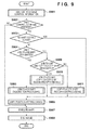
- FIG. 9 is a flowchart illustrating a shift control process carried out by the main controller 201 in the printing apparatus 100 according to the first working example.
- the programs that execute this processing are stored in the ROM 210 and are executed under the control of the CPU 205.
- the CPU 205 analyzes the discharge control information, added by the discharge control unit 228, that designates discharge processing related to each sheet of paper. Then, in S902, the CPU 205 determines whether or not a shift control command is set. In the case where the shift control command is not set, the process advances to S907, where shifting is executed using the current shift position settings, without changing the current shift position number in the shift setting information holding table ( FIG. 5A ). Then, in S908, the paper is shifted and discharged.
- the process advances to S903, where the CPU 205 determines whether or not a no-shift setting is active.
- the process advances to S906, where a shift position number of 0, indicating no shift, is set as the current shift position number in the shift setting information holding table ( FIG. 5A ), after which the process advances to S907.
- the process advances to S904, where the CPU 205 determines whether or not only a job-to-job shift setting is active. In the case where only the job-to-job shift setting is active, the process advances to S905, where the job-to-job shift designating processing is carried out.
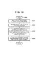
- FIG. 10 is a flowchart illustrating the job-to-job shift designating processing, carried out in S905 of FIG. 9 .
- the CPU 205 selects, from the shift group management table ( FIG. 5C ), a group (job) corresponding only to a job-to-job shift.
- the corresponding position number group is "1 and 2".
- the CPU 205 obtains the previously-used job-to-job shift position number from the shift setting information holding table ( FIG. 5A ).
- the shift position is determined as "2". Then, in S1004, the shift position number that has been determined ("2" in this case) is set and saved as the previously-used job-to-job shift position number in the shift setting information holding table ( FIG. 5A ) by the CPU 205.
- the process then advances to S906 in FIG. 9 , where the CPU 205 changes the shift position setting by saving the determined shift position number as the current shift position number in the shift setting information holding table ( FIG. 5A ).
- the process then advances to S907, where the shift is executed, and in S909, the paper is shifted and discharged.
- the process advances to S909.
- the CPU 205 determines whether or not both a job-to-job shift and a copy-to-copy shift are set. In the case where both shifts are set, the process advances to S910, where the job-to-job and copy-to-copy shift designating processing are carried out.
- FIG. 11 is a flowchart illustrating job-to-job and copy-to-copy shift designating processing, carried out in S910 of FIG. 9 .
- the CPU 205 determines whether the job-to-job shift has been set first. In the case where the job-to-job shift has been set first, the process advances to S1102, where the CPU 205 obtains the previously-used job-to-job shift position number by referring to the shift setting information holding table ( FIG. 5A ). Then, in S1103, the CPU 205 determines a group, among the groups from the shift group management table ( FIG. 5C ) that correspond to both a job-to-job shift and a copy-to-copy shift, that does not include the obtained shift position number, as a corresponding shift group.
- the CPU 205 determines the job-to-job shift position number included in a corresponding shift number of the corresponding shift group as a shift designation position. Then, in S1105, the CPU 205 saves the determined shift position number as the previously-used job-to-job shift position number in the shift setting information holding table ( FIG. 5A ). The process then advances to S906 in FIG. 9 , where the CPU 205 changes the shift position setting by saving the determined shift position number as the current shift position number in the shift setting information holding table ( FIG. 5A ). Then, in S907, the shift is executed, and in S908, the paper is shifted and discharged.
- the process advances to S1106.
- the CPU 205 then obtains the previously-used job-to-job shift position number from the shift setting information holding table ( FIG. 5A ).
- the CPU 205 determines a group, among the groups from the shift group management table ( FIG. 5C ) that correspond to both a job-to-job shift and a copy-to-copy shift, that includes the obtained shift position number, as the corresponding shift group.
- the CPU 205 obtains the current shift position number from the shift setting information holding table ( FIG. 5A ).
- the CPU 205 determines a position number, among the corresponding shift numbers of the corresponding shift group, that is not the current shift position number, as the shift designation position. Then, in S1110, the CPU 205 refers to the shift group management table ( FIG. 5C ), and determines whether the shift position number determined in S1109 indicates a job-to-job group. In the case where the shift position number indicates the job-to-job group, the process advances to S1111, where the CPU 205 saves the determined shift position number as the previously-used job-to-job shift position number in the shift setting information holding table ( FIG. 5A ).
- the process advances to S1112, where the CPU 205 saves the determined shift position number as the previously-used copy-to-copy shift position number in the shift setting information holding table ( FIG. 5A ).
- the process then advances to S906 in FIG. 9 , where the CPU 205 changes the shift position setting by saving the determined shift position number as the current shift position number in the shift setting information holding table ( FIG. 5A ).
- the shift is executed, and in S908, the paper is shifted and discharged.
- the process advances to S911, where copy-to-copy shift setting processing is carried out.
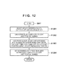
- FIG. 12 is a flowchart illustrating the copy-to-copy shift setting processing carried out in S911 of FIG. 9 .
- the CPU 205 selects, from the shift group management table ( FIG. 5C ), a group corresponding only to copy-to-copy shifting.
- the CPU 205 obtains the previously-used copy-to-copy shift position number from the shift setting information holding table ( FIG. 5A ).
- a number, among the shift position numbers corresponding to the shift group selected in S1201, that is not the previously-used copy-to-copy shift position number ("4", the examples of FIGS. 5A to 5C ) is determined as the shift designation.
- the CPU 205 saves the shift position number determined in S1203 as the final copy-to-copy shift position number in the shift setting information holding table ( FIG. 5A ).
- the process then advances to S906 in FIG. 9 , where the CPU 205 changes the shift designation position by saving the determined shift position number as the current shift position number in the shift setting information holding table ( FIG. 5A ).
- the shift is executed, and in S908, the paper is shifted and discharged.
- a single group for example, "1 and 3" is selected from among a plurality of groups, and printed sheets are shifted and discharged, for each copy of the first job, in accordance with a plurality of pieces of position information included in the selected group.
- another group for example, "2 and 4” is selected from among the plurality of groups, and printed sheets are shifted and discharged, for each copy of the second job, in accordance with a plurality of pieces of position information included in the selected group ("2 and 4").
- left and right discharge positions are split into groups on a job-by-job basis, and the sheets are discharged after changing the shift positions for each copy within the group.
- a shift function capable of changing among a plurality (at least four) discharge positions can be executed in the case where a print job in which both job-to-job shifting and copy-to-copy shifting are designated has been loaded.
- the paper can be discharged at different shift positions from print job to print job and from copy to copy within a single job, making it easy to identify printed sheets on a job-by-job basis and a copy-by-copy basis.
- the second working example describes an example in which printed sheets are shifted and discharged so that in addition to the job-to-job and copy-to-copy shifting described in the aforementioned first working example, shifts are carried out for each of chapters included in a print job (called "chapter-to-chapter shifting" hereinafter) so that the three types of printed material can be distinguished from one another.
- chapter-to-chapter shifting hereinafter
- the configuration of the printing apparatus 100 and the hardware configuration of the image forming apparatus according to the second working example are the same as those in the first working example, and thus descriptions thereof will be omitted.
- FIG. 13A is a diagram illustrating an example of the shift setting information holding table according to the present second working example.
- This shift setting information holding table is held in the shift control information storage unit 230.
- a currently-set shift position number (a current shift position number), the previously-used job-to-job shift position number, and previously-used copy-to-copy and chapter-to-chapter shift position numbers are registered and managed in the table.
- FIG. 13B is a diagram illustrating an example of the shift group management table according to the second working example.
- This table is a table for managing a plurality of shift positions in the shift position management table ( FIG. 5B ) as a group.
- This management table is used to manage the grouping of shift positions into a job-to-job shift position group used only for job-to-job shifting and a group in which job-to-job shifting, copy-to-copy shifting, and chapter-to-chapter shifting are carried out in parallel.
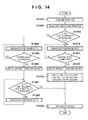
- FIG. 14 is a flowchart illustrating a control process carried out by the main controller 201 in the printing apparatus 100 according to the second working example.
- the programs that execute this processing are stored in the ROM 210 and are executed under the control of the CPU 205.
- the CPU 205 analyzes the received job along with the job control unit 225 and obtains control information as described below. A number of copies (copy number; N), a shift designation (job-to-job, copy-to-copy, chapter-to-chapter shift), a paper feed designation, discharge processing information (stapling, discharge destination), and so on are obtained as the information. Then, in S1402, the CPU 205 saves the obtained information in the job control information storage unit 226. Then, in S1403, the CPU 205 determines whether or not only a job-to-job shift is designated, based on the information saved in the job control information storage unit 226.
- the process advances to S1404, where the RIP 221 generates rasterized image data for each page to be printed and saves the data in the RAM 206. Then, in S1405, the CPU 205 determines whether or not rasterized image data has been generated up to and including the leading sheet of the print job. In the case where the image data has been generated up to and including the leading sheet, the process advances to S1406, where the CPU 205 sets a designation for job-to-job shifting in the discharge control information related to the leading sheet, and saves the information in the RAM 206.
- the RIP 221 In S1408, the RIP 221 generates rasterized image data on a page-by-page basis and stores the data in the RAM 206 until it is determined in S1407 that the image data has been generated up to and including the final page of the job. When it is determined in S1407 that the image data has been generated up to and including the last page of the job, the process advances to S1409. In S1409, the CPU 205 prints all of the copies designated in the print job based on the rasterized image data and the discharge control information saved in the RAM 206.
- the process advances to S1410, where the RIP 221 generates rasterized image data for each page and saves the data in the RAM 206.
- the CPU 205 determines whether or not rasterized image data has been generated up to and including the leading sheet of the print job, and when up to and including the leading sheet has been rasterized, the process advances to S1412.
- the CPU 205 sets a designation for job-to-job shifting in the discharge control information related to the leading sheet, and saves the information in the RAM 206.
- the process then advances to S1413, where job-to-job, copy-to-copy, and chapter-to-chapter shift designating processing is carried out.
- FIG. 15 is a flowchart illustrating processing carried out in S1413 of FIG. 14 .
- the CPU 205 determines whether or not rasterized image data has been generated for the last sheet of a chapter. In the case where the rasterized image data has not been generated for the last sheet of the chapter, the process advances to S1502, where the RIP 221 generates the rasterized image data for each page; the process then advances to S1501, where up to and including the last sheet of the chapter are saved in the RAM 206. In this manner, when it is determined that the rasterized image data has been generated up to and including the last sheet of the chapter, the process advances to S1503, where the CPU 205 determines whether or not there is a next chapter.
- the process advances to S1504, where the RIP 221 generates rasterized image data for each page and saves the data in the RAM 206. Then, in S1505, the CPU 205 determines whether or not rasterized image data has been generated up to and including the leading sheet of the chapter. When the rasterized image data is generated for up to and including the leading sheet of the chapter in this manner, the process advances to S1506, where the CPU 205 sets a copy-to-copy shifting and chapter-to-chapter shifting designation in the discharge control information related to the leading sheet of the chapter and saves the information in the RAM 206.
- the CPU 205 determines whether or not rasterized image data has been generated up to and including the last sheet of the chapter, and the process advances to S1508 in the case where the rasterized image data has not been generated for the last sheet of the chapter.
- the CPU 205 generates the rasterized image data for each page using the RIP 221 and saves the data in the RAM 206, after which the process returns to S1507.
- the process returns to S1503 from S1507.
- the process advances to S1509, where the CPU 205 determines whether or not there is a next copy. In the case where it is determined that there is no next copy, the process returns to S1409 of FIG. 14 , where all of the copies designated in the print job are printed based on the rasterized image data and the discharge control information saved in the RAM 206. On the other hand, in the case where it is determined in S1509 that there is a next copy to be processed, the process advances to S1510, where the RIP 221 generates rasterized image data for each page and saves the data in the RAM 206.
- the CPU 205 determines whether or not rasterized image data has been generated up to and including the leading sheet of the copy, and when up to and including the leading sheet has been rasterized, the process advances to S1512.
- the CPU 205 sets a designation for job-to-job shifting, copy-to-copy shifting, and chapter-to-chapter shifting in the discharge control information related to the leading sheet of the copy, and saves the information in the RAM 206.
- the CPU 205 determines whether or not rasterized image data has been generated for the last sheet of the chapter.
- the process advances to S1514, where the RIP 221 generates the rasterized image data for each page and saves the data in the RAM 206, after which the process returns to S1513.
- the CPU 205 determines in S1513 that the rasterized image data has been generated up to and including the last sheet of the chapter, the process returns to S1503, where the same processing as described above is executed.
- FIG. 16 is a flowchart illustrating a shift control process carried out by the main controller 201 in the printing apparatus 100 according to the second working example.
- the programs that execute this processing are stored in the ROM 210 and are executed under the control of the CPU 205.
- the CPU 205 analyzes the discharge control information, added by the discharge control unit 228, that designates discharge processing related to each sheet of paper. Then, in S1602, the CPU 205 determines whether or not a shift control command is set. In the case where it is determined that the shift control command is not set, the process advances to S1606, where shifting is executed using the current shift position settings, without changing the current shift position number in the shift setting information holding table ( FIG. 13A ). Then, in S1607, the paper is shifted and discharged.
- the process advances to S1603, where the CPU 205 determines whether or not only a job-to-job shift setting is active. In the case where only the job-to-job shifting is designated, the process advances to S1604, where the CPU 205 carries out the job-to-job shift designating processing.
- FIG. 17 is a flowchart illustrating the job-to-job shift designating processing, carried out in S1604 of FIG. 16 .
- the CPU 205 selects, from the shift group management table ( FIG. 13B ), a group (job) corresponding only to a job-to-job shift. Then, in S1702, the CPU 205 obtains the previously-used job-to-job shift position number from the shift setting information holding table ( FIG. 13A ). Then, in S1703, a number, among the corresponding shift numbers in the shift group selected in S1701, that is not the previously-used job-to-job shift position number is determined as the shift designation. Then, in S1704, the CPU 205 saves the determined shift position number as the previously-used job-to-job shift position number in the shift setting information holding table ( FIG. 13A ).
- the process then returns to S1605 in FIG. 16 , where the CPU 205 changes the shift position setting by saving the determined shift position number as the current shift position number in the shift setting information holding table ( FIG. 13A ). Then, in S1606, the shift is executed, and in S1607, the paper is shifted and discharged.
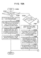
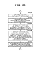
- FIGS. 18A and 18B are flowcharts illustrating the copy-to-copy shift and chapter-to-chapter shift designating processing, carried out in S1608 of FIG. 16 .
- the CPU 205 determines whether or not only the job-to-job shift has been set. In the case where it is determined that only the job-to-job shift is set, the process advances to S1802, where the CPU 205 obtains the previously-used job-to-job shift position number from the shift setting information holding table ( FIG. 13A ). Then, in S1803, the CPU 205 determines, as the corresponding shift group, a copy-to-copy and chapter-to-chapter group that does not include the shift position number obtained from the shift group management table ( FIG. 13B ). Then, in S1804, the CPU 205 determines the job-to-job shift position number included in the corresponding shift number of the corresponding shift group as the shift designation position.
- the CPU 205 saves the determined shift position number as the previously-used job-to-job shift position number in the shift setting information holding table ( FIG. 13A ).
- the process then advances to S1605 in FIG. 16 , where the CPU 205 changes the shift position setting by saving the determined shift position number as the current shift position number in the shift setting information holding table ( FIG. 13A ).
- the shift is executed, and in S1607, the paper is shifted and discharged.
- the process advances to S1806 where it is determined if all of the job-to-job, copy-to-copy, and chapter-to-chapter shift settings are active.
- the process advances to S1807, where the CPU 205 obtains the previously-used job-to-job shift position number from the shift setting information holding table ( FIG. 13A ).
- the CPU 205 determines, as the corresponding shift group, a copy-to-copy and chapter-to-chapter shift group that includes the shift position number obtained from the shift group management table ( FIG. 13B ).
- the CPU 205 determines the job-to-job shift position number included in the corresponding shift number of the corresponding shift group as the shift designation position. Then, in S1810, the CPU 205 saves the determined shift position number as the previously-used job-to-job shift position number in the shift setting information holding table ( FIG. 13A ). The process then advances to S1605 in FIG. 16 , where the CPU 205 changes the shift position setting by saving the determined shift position number as the current shift position number in the shift setting information holding table ( FIG. 13A ). Then, in S1606, the shift is executed, and in S1607, the paper is shifted and discharged.
- the process advances to S1811.
- the CPU 205 obtains the previously-used job-to-job shift position number from the shift setting information holding table ( FIG. 13A ).
- the CPU 205 obtains the previously-used copy-to-copy and chapter-to-chapter shift position numbers from the shift setting information holding table ( FIG. 13A ).
- the CPU 205 determines the copy-to-copy and chapter-to-chapter shift group including both of the obtained shift position numbers as the corresponding shift group.
- the CPU 205 sets copy-to-copy and chapter-to-chapter shift position numbers, among the corresponding shift numbers of the determined corresponding shift group, that are not the previously-used copy-to-copy and chapter-to-chapter shift position numbers, as the shift designation positions.
- the CPU 205 saves the determined shift position numbers as the previously-used copy-to-copy and chapter-to-chapter shift position numbers in the shift setting information holding table ( FIG. 13A ).
- the process then advances to S1605 in FIG. 16 , where the CPU 205 changes the shift position setting by saving the determined shift position number as the current shift position number in the shift setting information holding table ( FIG. 13A ).
- the shift is executed, and in S1607, the paper is shifted and discharged.
- a shift function capable of changing among a plurality (at least four) discharge positions can be executed in the case where a print job in which job-to-job, copy-to-copy, and chapter-to-chapter shifting are designated has been loaded. Accordingly, printed materials can be shifted and the discharge positions thereof changed from print job to print job as well as from copy to copy and chapter to chapter within a job, making it possible to easily identify those printed materials.
- the third working example describes an example in which four or more shift positions (five, in the third working example) are divided into the following two groups and control is carried out based thereon.
- Shift positions used in normal job-to-job and copy-to-copy shifts will be referred to as "normal shifting”
- shift positions used only for sheets affected by a state change during printing a paper jam, automatic darkness control, a sheet feed tray switch, or the like
- the configuration of the printing apparatus 100 and the hardware configuration of the image forming apparatus according to the third working example are the same as those in the first working example, and thus descriptions thereof will be omitted.
- FIG. 19A is a diagram illustrating an example of a shift setting information holding table according to the present third working example.
- This table is a management table, held in the shift control information storage unit 230, that holds and manages current and past information related to shift settings such as the following:
- FIG. 19B is a diagram illustrating an example of the shift group management table according to the third working example.
- This table is a table for managing a plurality of shift positions in the shift position management table ( FIG. 5B ) as a group.
- This management table is used for managing the grouping of shift positions into a group of shift positions used in normal shifting (a first group) and a group used in special shifting (a second group).
- FIG. 20 is a flowchart illustrating a control process carried out by the main controller 201 in the printing apparatus 100 according to the third working example.
- the programs that execute this processing are stored in the ROM 210 and are executed under the control of the CPU 205.
- the CPU 205 upon receiving a print job, analyzes the received job along with the job control unit 225 and obtains control information such as the number of copies (a copy number; N), shift designations (job-to-job, copy-to-copy), a paper feed designation, discharge processing information (stapling, discharge destination), and so on. Then, in S2002, the CPU 205 saves the obtained information in the job control information storage unit 226. Then, in S2003, the RIP 221 generates rasterized image data for each page and saves the data in the RAM 206.
- control information such as the number of copies (a copy number; N), shift designations (job-to-job, copy-to-copy), a paper feed designation, discharge processing information (stapling, discharge destination), and so on.
- the CPU 205 saves the obtained information in the job control information storage unit 226.
- the RIP 221 generates rasterized image data for each page and saves the data in the RAM 206.
- the CPU 205 determines whether or not rasterized image data has been generated up to and including the leading sheet of the print job, and when up to and including the leading sheet has been rasterized, the process advances to S2005.
- the CPU 205 determines whether or not normal shifting (job-to-job shifting or copy-to-copy shifting) is designated based on the information saved in the job control information storage unit 226. In the case where it is determined that normal shifting is designated, the process advances to S2006, where the CPU 205 sets a normal shifting designation in the discharge control information related to the leading sheet and saves the information in the RAM 206.
- the CPU 205 determines whether or not rasterized image data has been generated for the last sheet of the copy.
- the process advances to S2008, where the RIP 221 generates the rasterized image data for each page and saves the data in the RAM 206, after which the process returns to S2007.
- the process advances to S2009, where the CPU 205 determines whether or not there is a next copy.
- the process returns to S2003 in the case where it is determined that there is a next copy.
- the process advances to S2010, where all of the copies designated in the print job are printed based on the rasterized image data and the discharge control information saved in the RAM 206.
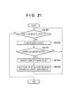
- FIG. 21 is a flowchart illustrating a process for setting special shift control according to the third working example.
- the programs that execute this processing are stored in the ROM 210 and are executed under the control of the CPU 205.
- the CPU 205 determines whether or not a print job is being executed. In the case where a print job is being executed, the process advances to S2102, where the CPU 205 monitors whether or not a state change (a paper jam, automatic darkness adjustment, a sheet feed tray switch, or the like) has occurred. In the case where the CPU 205 has not detected a state change in S2103, the process returns to S2101, whereas in the case where the CPU 205 has detected a state change in S2103, the process advances to S2104. In S2104, the CPU 205 specifies the first sheet to be printed following the state change. Then in S2105, the CPU 205 sets a normal shifting designation in the discharge control information related to the specified sheet, after which the process returns to S2101. When the execution of the print job ends in S2101, the processing indicated in this flowchart ends.
- a state change a paper jam, automatic darkness adjustment, a sheet feed tray switch, or the like
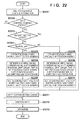
- FIG. 22 is a flowchart illustrating a shift control process carried out by the main controller 201 in the printing apparatus 100 according to the third working example.
- the programs that execute this processing are stored in the ROM 210 and are executed under the control of the CPU 205.
- the CPU 205 analyzes the discharge control information, added by the discharge control unit 228, that designates discharge processing related to each sheet of paper. Then, in S2202, the CPU 205 determines whether or not a shift control command is set. In the case where it is determined that the shift control command is not set, the process advances to S2212, where the CPU 205 executes the shift using the current shift position settings, without changing the current shift position number in the shift setting information holding table ( FIG. 19A ). Then, in S2213, the paper is shifted and discharged.
- the process advances to S2203, where the CPU 205 determines whether a no-shift setting is active.
- the process advances to S2211, where a shift position number of 0, indicating no shift, is set as the current shift position number in the shift setting information holding table ( FIG. 19A ), thus changing the shift position setting.
- S2212 the shift is executed, and in S2213, the paper is shifted and discharged.
- the process advances to S2204, where the CPU 205 determines whether or not a normal shift setting is active.
- the process advances to S2205.
- the CPU 205 obtains a previously-used normal shift position number from the shift setting information holding table ( FIG. 19A ).
- the CPU 205 determines a number, among the corresponding shift numbers in a normal shift group in the shift group management table ( FIG. 19B ), that is not the obtained previously-used normal shift position number, as the shift designation.
- the CPU 205 saves the determined shift position number as the previously-used normal shift position number in the shift setting information holding table ( FIG. 19A ). Then, in S2211, the CPU 205 changes the shift position setting by saving the determined shift position number as the current shift position number in the shift setting information holding table ( FIG. 19A ). The process then advances to S2212, where the shift is executed, and in S2213, the paper is shifted and discharged.
- the process advances to S2208.
- the CPU 205 obtains a previously-used special shift position number from the shift setting information holding table ( FIG. 19A ).
- the CPU 205 determines a number, among the corresponding shift numbers in a special shift group in the shift group management table ( FIG. 19B ), that is not the obtained previously-used special shift position number, as the shift designation.
- the CPU 205 saves the determined shift position number as the previously-used special shift position number in the shift setting information holding table ( FIG. 19A ).
- the process then advances to S2211, where the aforementioned processing is executed.
- the fourth working example describes an example in which state changes that trigger special shifting can be selected, in the shift control where special shifting is carried out after a state change in the device as described in the aforementioned third working example.
- the configuration of the printing apparatus 100 and the hardware configuration of the image forming apparatus according to the fourth working example are the same as those in the first working example, and thus descriptions thereof will be omitted.
- FIG. 23B is a diagram illustrating an example of a screen for setting device states in which special shifting is to be carried out (special shift setting registration), displayed in the console section 104 of the printing apparatus 100 according to the fourth working example.
- 2301 to 2304 each indicate device states that can be detected by the device state monitoring unit 231. Whether to execute special shifting (on) or not to execute special shifting (off) is set for each state.
- “on” is set for paper jams and errors, as indicated by 2305 and 2308, whereas “off” is set for auto tone correction and sheet feed tray changes, as indicated by 2306 and 2307.
- the CPU 205 saves the special shift setting registration in a special shift corresponding state registration table ( FIG. 23A ) held in the shift control information storage unit 230.
- FIG. 24 is a flowchart illustrating a process for setting special shift control in the printing apparatus 100 according to the fourth working example.
- the programs that execute this processing are stored in the ROM 210 and are executed under the control of the CPU 205.
- the CPU 205 determines whether or not a print job is being executed. In the case where it is determined that a print job is being executed, the process advances to S2402, where the device state monitoring unit 231 monitors whether or not a state change (a paper jam, automatic darkness adjustment, a sheet feed tray switch, or the like) has occurred during printing. Then, in S2403, when the CPU 205 detects a state change, the process advances to S2404. In S2404, the CPU 205 determines whether or not a special shift is registered as "on" for the detected state change in the special shift corresponding state registration table ( FIG. 23A ). In the case where it is determined that the special shift is registered as "off", the process returns to S2401.
- a state change a paper jam, automatic darkness adjustment, a sheet feed tray switch, or the like
- the process advances to S2406, where the CPU 205 specifies the first sheet printed following the state change.
- the CPU 205 sets a special shifting designation in the discharge control information related to the specified sheet, after which the process returns to S2401 and the aforementioned state change detection is continued while the print job is being executed.
- Other processes are the same as those described in the aforementioned third working example and thus descriptions thereof will be omitted.
- Embodiments of the present invention can also be realized by a computer of a system or apparatus that reads out and executes computer executable instructions recorded on a storage medium (e.g., non-transitory computer-readable storage medium) to perform the functions of the above-described embodiment of the present invention, and by a method performed by the computer of the system or apparatus by, for example, reading out and executing the computer executable instructions from the storage medium to perform the functions of the above-described embodiments.
- the computer may comprise one or more of a central processing unit (CPU), micro processing unit (MPU), or other circuitry, and may include a network of separate computers or separate computer processors.
- the computer executable instructions may be provided to the computer, for example, from a network or the storage medium.
- the storage medium may include, for example, one or more of a hard disk, a random-access memory (RAM), a read only memory (ROM), a storage of distributed computing systems, an optical disk (such as a compact disc (CD), digital versatile disc (DVD), or Blu-ray Disc (BD)TM), a flash memory device, a memory card, and the like.
- RAM random-access memory
- ROM read only memory
- BD Blu-ray Disc
Landscapes
- Physics & Mathematics (AREA)
- General Physics & Mathematics (AREA)
- Control Or Security For Electrophotography (AREA)
- Accessory Devices And Overall Control Thereof (AREA)
- Paper Feeding For Electrophotography (AREA)
- Facsimiles In General (AREA)
- Forming Counted Batches (AREA)
- Engineering & Computer Science (AREA)
- Mechanical Engineering (AREA)
Abstract
Description
- The present invention relates to control apparatuses, control methods, and storage media that control the discharge position of a sheet.
- Among image forming apparatuses that include discharge devices having discharge functions, a "shift function" that places output paper (printed material) at the same discharge destination (tray) while changing the discharge position (position in said tray) of the output paper is known. Using this shift function to shift the discharge position of printed material from print job to print job and to stack the shifted printed material makes it possible to distinguish the printed material that corresponds to a given print job with ease (this will be referred to as "job-to-job shifting" hereinafter). Likewise, when executing a print job in which a certain number of printed copies is specified, shifting the printed material from copy to copy and stacking the printed material makes it possible to distinguish the printed material that corresponds to a given copy with ease (this will be referred to as "copy-to-copy shifting" hereinafter) (see Japanese Patent Laid-Open No.
2008-150204 - However, according to the aforementioned past techniques, the discharge position is limited to two positions, namely a shifted position and an unshifted position, and thus printed materials discharged to the same discharge destination cannot be distinguished from each other based on the print job and based on individual copies within that print job at the same time.
- Meanwhile, in the case where the state of a printing apparatus has changed during printing (a paper jam has occurred, for example), it is conceivable to use the shift function to identify where, in the discharged and stacked printed materials, it is likely that the state change began to affect the printed materials. However, in such a case, it is not possible to discern whether the shift function has been used for that purpose, or for identifying job-to-job shifting or copy-to-copy shifting. Separating printed materials using separately-prepared partition paper or the like can thus be considered, but this poses an additional problem in that paper is wasted in order to produce the partition paper.
- The present invention enables the realization of a technique that enables job-to-job shift and copy-to-copy shift to be distinguished from each other.
- According to a first aspect of the present invention there is provided a control apparatus according to
claims 1 to 5. - According to a second aspect of the present invention there is provided a method for controlling the control apparatus according to claim 6.
- According to a third aspect of the present invention there is provided a computer-readable storage medium as specified in claim 7.
- Further features of the present invention will become apparent from the following description of embodiments (with reference to the attached drawings).
-
-
FIG. 1 is a cross-sectional view illustrating an example of the configuration of an image forming apparatus according to an embodiment of the present invention. -
FIG. 2 is a block diagram illustrating the configuration of a main controller in a printing apparatus according to the embodiment. -
FIGS. 3A to 3C are diagrams illustrating paper being shifted and discharged by shifting the position of a discharge roller, according to the embodiment. -
FIG. 4 is a diagram illustrating an example of the result of discharging paper shifted according to a shift position management table (FIG. 5B ) according to the embodiment. -
FIGS. 5A to 5C are diagrams illustrating tables according to the embodiment, whereFIG. 5A illustrates a shift setting information holding table,FIG. 5B illustrates the shift position management table, andFIG. 5C illustrates a shift group management table. -
FIG. 6 is a flowchart illustrating a control process carried out by the main controller in the printing apparatus according to a first working example. -
FIG. 7 is a flowchart illustrating job-to-job and copy-to-copy shift designating processing, carried out in S614 ofFIG. 6 . -
FIG. 8 is a flowchart illustrating copy-to-copy shift designating processing, carried out in S615 ofFIG. 6 . -
FIG. 9 is a flowchart illustrating a shift control process carried out by the main controller in the printing apparatus according to the first working example. -
FIG. 10 is a flowchart illustrating job-to-job shift designating processing, carried out in S905 ofFIG. 9 . -
FIG. 11 is a flowchart illustrating job-to-job and copy-to-copy shift designating processing, carried out in S910 ofFIG. 9 . -
FIG. 12 is a flowchart illustrating setting processing for copy-to-copy shifts, carried out in S911 ofFIG. 9 . -
FIGS. 13A and 13B are diagrams illustrating tables according to a second working example, whereFIG. 13A illustrates an example of a shift setting information holding table, andFIG. 13B illustrates an example of a shift group management table. -
FIG. 14 is a flowchart illustrating a control process carried out by the main controller in the printing apparatus according to the second working example. -
FIG. 15 is a flowchart illustrating processing carried out in S1413 ofFIG. 14 . -
FIG. 16 is a flowchart illustrating a shift control process carried out by the main controller in the printing apparatus according to the second working example. -
FIG. 17 is a flowchart illustrating job-to-job shift designating processing, carried out in S1604 ofFIG. 16 . -
FIGS. 18A and18B are flowcharts illustrating copy-to-copy and chapter-to-chapter shift designating processing, carried out in S1608 ofFIG. 16 . -
FIGS. 19A and 19B are diagrams illustrating tables according to the second working example, whereFIG. 19A illustrates an example of a shift setting information holding table, andFIG. 19B illustrates an example of a shift group management table. -
FIG. 20 is a flowchart illustrating a control process carried out by the main controller in the printing apparatus according to a third working example. -
FIG. 21 is a flowchart illustrating a process for setting special shift control according to the third working example. -
FIG. 22 is a flowchart illustrating a shift control process carried out by the main controller in the printing apparatus according to the third working example. -
FIGS. 23A and 23B are diagrams illustrating a table and a screen example according to the third working example, whereFIG. 23A illustrates an example of a special shift correspondence state table andFIG. 23B illustrates an example of a screen for setting a device state in which special shifting is to be carried out (special shift setting registration). -
FIG. 24 is a flowchart illustrating a process for setting special shift control in a printing apparatus according to a fourth working example. - Embodiments of the present invention will now be described in detail with reference to the drawings. It should be noted that the relative arrangement of the components, the numerical expressions and numerical values set forth in the embodiments do not limit the scope of the present invention unless it is specifically stated otherwise. Each of the embodiments of the present invention described below can be implemented solely or as a combination of a plurality of the embodiments or features thereof where necessary or where the combination of elements or features from individual embodiments in a single embodiment is beneficial.
-
FIG. 1 is a cross-sectional view illustrating an example of the configuration of an image forming apparatus according to an embodiment of the present invention. Aprinting apparatus 100 will be described here as an example of the image forming apparatus. - The
printing apparatus 100 includes animage forming section 101, afixing section 102, ascanner section 103, aconsole section 104, apaper discharge section 107, atoner supply section 110, and an externalsheet feed section 118.Sheet feed units conveyance unit 108, aprimary transfer unit 111, atransfer belt 112, and asecondary transfer unit 113 are provided in theimage forming unit 101. Aswitchback unit 109, a wastetoner holding unit 114, fixingunits conveyance units fixing section 102. Aconveyance unit 119 andsheet feed units sheet feed section 118. - The
scanner section 103 optically reads an original document and generates electronic data representing an image of that document. Theconsole section 104 accepts various types of instructions for theprinting apparatus 100 made by an operator. Theconsole section 104 is provided with a display unit having touch panel functionality along with physical keys. Thesheet feed units printing apparatus 100. Thepaper discharge section 107 discharges the paper printed onto by theprinting apparatus 100 to the exterior of theprinting apparatus 100. 124 indicates a shift mechanism unit, which is a mechanism unit for realizing a shift function, described later. - In the conveyance units, rollers for conveying the paper are provided at set intervals. The
switchback unit 109 inverts the output surface of the paper when the paper is discharged to thepaper discharge section 107. Thetoner supply section 110 supplies toner, serving as a developer, to theimage forming section 101. Theprimary transfer unit 111 transfers a toner image formed based on image data onto thetransfer belt 112. Thesecondary transfer unit 113 transfers the toner image, transferred onto thetransfer belt 112, onto paper. The wastetoner holding unit 114 holds excess toner resulting from the transfer process. The fixingunit 115 fixes the toner onto the paper by applying heat and pressure to the paper onto which the image has been transferred by thesecondary transfer unit 113. The fixingunit 116 reinforces the fix of the image by applying further heat and pressure to the paper onto which the image has been fixed by the fixingunit 115. Theconveyance units conveyance unit 117 forms a conveyance path for conveying the paper from the fixingunit 115 to the fixingunit 116. Theconveyance unit 123 forms a conveyance path for conveying the paper from the fixingunit 115 to thepaper discharge section 107 or theswitchback unit 109 without passing through the fixingunit 116. Theconveyance units sheet feed units printing apparatus 100. -
FIG. 2 is a block diagram illustrating the configuration of amain controller 201 in theprinting apparatus 100 according to the present embodiment. - The
main controller 201 includes aCPU 205, aRAM 206, a console unit I/F 207, a network I/F 208, amodem 209, aROM 210, and anHDD 211. These elements are connected via an image bus I/F 213 to animage bus 224 that connects aCPU bus 212, an RIP I/F 214, adata compression unit 215, a device I/F 216, and an image processing unit 217. - A
network cable 203 for connecting to an external device via a network is connected to the network I/F 208. Aline cable 204 for connecting to an external device over a telephone line is connected to themodem 209. TheCPU 205 runs programs for controlling themain controller 201 as a whole. TheRAM 206 is managed by a program run by theCPU 205. TheRAM 206 is used as a receiving buffer for temporarily holding data received from the exterior, as an image memory for temporarily holding image data rasterized by aRIP 221, and so on. TheROM 210 stores programs run by theCPU 205, data, and so on. TheHDD 211 is a non-volatile storage device capable of saving various types of data for long periods of time. - The console unit I/
F 207 is an interface for connecting theconsole section 104 and themain controller 201. TheRIP 221 is connected to the RIP I/F 214 via adata bus 218. TheRIP 221 is a raster image processor having functionality for converting image format data input from the exterior into bitmap image data. The RIP I/F 214 is an interface for connecting theRIP 221 and theimage bus 224 via thedata bus 218. Thedata compression unit 215 compresses data. - Meanwhile, a paper feed/
discharge unit 222 is connected to the device I/F 216 via adata bus 219, and aprinter 223 is connected to the device I/F 216 via adata bus 220. The configuration of theprinter 223 is as described above usingFIG. 1 . TheCPU 205 issues commands for printing to theprinter 223 and the paper feed/discharge unit 222 via thedata buses console section 104, an external device via thenetwork cable 203, or the like. TheCPU 205 also issues commands specifying discharge processes such as shifting, punching, and so on to a control apparatus included in the paper feed/discharge unit 222, based on the paper printed onto. - The image processing unit 217 executes various types of image processes on the bitmap image data generated by the
RIP 221. The image processing unit 217 includes a function for processing the bitmap image data digitally, such as a function for combining two pages' worth of bitmap image data into a single page's worth of bitmap image data. Ajob control unit 225 analyzes data received from the exterior as a job, obtains control information such as a number of copies (a copy number; N), a paper feed designation, discharge processing information (shifting, stapling, a discharge destination), and so on, and controls the data as part of the job. A job controlinformation storage unit 226 is a region for storing the obtained control information. A paperfeed control unit 227 performs control related to paper feeding along with theCPU 205 and thejob control unit 225. Adischarge control unit 228 performs control related to paper discharge, on a paper-by-paper basis, along with theCPU 205 and thejob control unit 225. In particular, thedischarge control unit 228 issues discharge processing commands indicating processing to be performed in relation to the discharge control information, on a print paper-by-print paper basis, and manages the stated processing. Ashift control unit 229 performs specialized control for the shift function along with theCPU 205, thejob control unit 225, and thedischarge control unit 228. A shift controlinformation storage unit 230 holds control information necessary for managing theshift control unit 229. A devicestate monitoring unit 231 monitors states of theprinting apparatus 100 that arise during printing, along with theCPU 205 and thejob control unit 225. - Next, the shift function according to the present embodiment will be described.
- The shift function is a function in which printed paper (sheets on which images have been formed) are placed in the same discharge location but are slid (shifted) by a predetermined amount (an offset value) in a direction orthogonal to a direction in which the paper is discharged. In the present embodiment, a plurality (at least four) offset values are provided, and the paper is shifted and discharged to at least four different positions.
- As will be described with reference to
FIGS. 3A to 3C below, theshift mechanism unit 124 can shift the discharge direction of the paper by a predetermined amount in the direction orthogonal to the discharge direction of the paper by sliding adischarge roller 125, driven by a motor (not shown), in the direction orthogonal to the discharge direction of the paper. Here, the offset values that determine the predetermined amounts are managed by a shift setting information holding table (seeFIG. 5A ), which is held in the shift controlinformation storage unit 230 and will be described later. -
FIG. 3A is a side view of the fixingsection 102,FIG. 3B is a top view of the fixingsection 102, andFIG. 3C illustrates a state in which thedischarge roller 125 has been shifted upward relative to the state shown inFIG. 3B . Thedischarge roller 125 is structured to be capable of sliding to the left and right of (in the direction orthogonal to) the conveyance direction of the paper. When the conveyed paper is received by thedischarge roller 125, thedischarge roller 125 is moved to a position centered on the conveyance path (an offset of 0; a shift position number 0) (FIG. 3B ). After thedischarge roller 125 has received the paper, thedischarge roller 125 is shifted by the offset amount corresponding to the current shift position number in the shift position management table (FIG. 5B ), for each piece of paper that is conveyed. To be more specific, the paper can be discharged while shifting the position of the paper in the direction orthogonal to the conveyance direction by sliding thedischarge roller 125 by a predetermined amount (the offset value) to the left or right relative to the direction in which the paper advances and discharging the paper. -
FIG. 4 is a diagram illustrating an example of the result of discharging paper shifted according to the shift position management table (FIG. 5B ) according to the embodiment. - In
FIG. 4 , 400 indicates a discharge position in the case where the offset amount is 0. Discharge positions whose offset amounts are X, 2X, -X, and -2X relative to the offset amount of 0 are also indicated. - The shift position management table shown in
FIG. 5B is a table indicating sets of shift position numbers that uniquely indicate shift positions and corresponding offset amounts (position information). Here, an offset amount is negative when corresponding to the left direction relative to the direction in which paper advances along the conveyance path, and positive when corresponding to the right direction. Althoughshift position numbers 1 to 4 are set to be essentially horizontally symmetrical relative to the offset amount of 0 (no shift) here, the present invention is not limited thereto. - The shift setting information holding table in
FIG. 5A is an example of a management table held in the shift controlinformation storage unit 230. The shift setting information holding table is used to hold and manage current and past information related to shift settings, including a currently-set shift position number (current shift position setting information), a previously-used job-to-job shift position number, and a previously-used copy-to-copy shift position number. -
FIG. 5C illustrates an example of a shift group management table. This table is a table for managing a plurality of shift positions in the shift position management table as a group. A shift position group used only in job-to-job shifts, a group used when job-to-job and copy-to-copy shifts are used simultaneously, a group used only in copy-to-copy shifts, and so on are assigned and managed in the shift group management table. InFIG. 5C , the position numbers used only in job-to-job shifts are "1" and "2", and the groups used when job-to-job and copy-to-copy shifts are used simultaneously are "1 and 3" and "2 and 4". The group used only in copy-to-copy shifts is "3 and 4". - First, a first working example of the present invention will be described.
-
FIG. 6 is a flowchart illustrating a control process carried out by themain controller 201 in theprinting apparatus 100 according to the first working example. The programs that execute this processing are stored in theROM 210 and are executed under the control of theCPU 205. - First, in S601, upon receiving a print job, the
CPU 205 analyzes the received job and obtains control information such as the number of copies (a copy number; N), shift designations (job-to-job, copy-to-copy), a paper feed designation, discharge processing information (stapling, discharge destination), and so on. Then, in S602, theCPU 205 saves the obtained information in the job controlinformation storage unit 226. Next, in S603, theCPU 205 generates rasterized image data for each page that is to be printed using theRIP 221, and saves the image data in theRAM 206. Then, in S604, theCPU 205 determines whether or not rasterized image data has been generated up to and including the leading sheet of the print job. In the case where it is determined that up to and including the leading sheet has been rasterized, the process advances to S605, where theCPU 205 determines whether or not job-to-job shifting is designated based on the information saved in the job controlinformation storage unit 226. In the case where it is determined that job-to-job shifting is designated, the process advances to S606, where theCPU 205 determines whether or not copy-to-copy shifting is designated based on the information saved in the job controlinformation storage unit 226. In the case where copy-to-copy shifting is not designated, the process advances to S607, where theCPU 205 sets the job-to-job shift designation in the discharge control information related to the leading sheet and saves the setting in theRAM 206. Then, in S608, theCPU 205 determines whether or not rasterized image data has been generated up to and including the final sheet of the print job, and the process advances to S609 in the case where the process is not complete for up to and including the final sheet. In S609, theCPU 205 generates the image data for the next page, and the process advances to S608. In this manner, theRIP 221 generates the rasterized image data for each page to be printed in S608, and the process advances to S616 when up to and including the final page of the print job has been saved in theRAM 206. In S616, theCPU 205 prints all of the copies designated in the print job based on the rasterized image data and the discharge control information saved in theRAM 206. - On the other hand, in the case where it is determined in S606 that copy-to-copy shifting is designated, the process advances to S614, where designating processing for both job-to-job and copy-to-copy shifting is carried out.
-
FIG. 7 is a flowchart illustrating the job-to-job and copy-to-copy shift designating processing, carried out in S614 ofFIG. 6 . - First, in S701, the
CPU 205 sets a designation for job-to-job shifting and copy-to-copy shifting, in that order, in the discharge control information related to the leading sheet, and saves the information in theRAM 206. Then, in S702, theCPU 205 determines whether or not rasterized image data has been generated for the last sheet of the copy. In the case where it is determined that the rasterized image data has not been generated for the last sheet of the copy, the process advances to S703, where theRIP 221 generates the rasterized image data for the next page to be printed and saves the data in theRAM 206, after which the process returns to S702. In S702, in the case where theCPU 205 determines that the rasterized image data has been generated up to and including the last sheet of the copy, the process advances to S704, where theCPU 205 determines whether or not there is a next copy. In the case where it is determined that there is no copy to be processed, the process advances to S616 ofFIG. 6 , where all of the copies designated in the print job are printed based on the rasterized image data and the discharge control information saved in theRAM 206 during the printing process. - On the other hand, in the case where it is determined in S704 that there is a next copy to be processed, the process advances to S705, where the
CPU 205 generates rasterized image data for each page using theRIP 221 and saves the data in theRAM 206. Then, in S706, theCPU 205 determines whether or not rasterized image data has been generated up to and including the leading sheet of the copy. In the case where it is determined that up to and including the leading sheet has been completed, the process advances to S707, where theCPU 205 sets a designation for copy-to-copy shifting and job-to-job shifting, in that order, in the discharge control information related to the leading sheet of the copy, and saves the information in theRAM 206. Then, in S708, theCPU 205 determines whether or not rasterized image data has been generated for the last sheet of the copy, and in the case where it is determined that the rasterized image data has been generated up to and including the last sheet of the copy, the process returns to S704 and the aforementioned processing is carried out. On the other hand, in S708, in the case where it is determined that the rasterized image data has not been generated for the last sheet of the copy, the process advances to S709, where theCPU 205 generates the rasterized image data for the next page to be printed using theRIP 221 and saves the data in theRAM 206, after which the process returns to S708. - Returning once again to
FIG. 6 , in the case where it is determined in S605 that job-to-job shifting is not designated, the process advances to S610. In S610, theCPU 205 determines whether or not copy-to-copy shifting is designated based on the information saved in the job controlinformation storage unit 226. In the case where copy-to-copy shifting is not designated, the process advances to S611, where under the control of theshift control unit 229, theCPU 205 sets the discharge control information associated with the image data of the leading sheet to "no shift designation" and saves the setting in theRAM 206. Then, in S612 and S613, theRIP 221 generates rasterized image data for each page to be printed, up to and including the last sheet of the job, and saves the data in theRAM 206. Then, in S616, all of the copies designated in the print job are printed based on the rasterized image data and the discharge control information saved in theRAM 206. - In the case where the
CPU 205 determines in S610 that copy-to-copy shifting is designated, the process advances to S615, where the copy-to-copy shift designating processing is carried out. Details of this process will be described given with reference to the flowchart inFIG. 8 . -
FIG. 8 is a flowchart illustrating copy-to-copy shift designating processing, carried out in S615 ofFIG. 6 . - First, in S801, the
CPU 205 sets a designation for copy-to-copy shifting in the discharge control information related to the leading sheet, and saves the information in theRAM 206. Then, in S802, theCPU 205 determines whether or not rasterized image data has been generated for the last sheet of the copy, using thejob control unit 225. In the case where it is determined that the rasterized image data has not been generated for the last sheet of the copy, the process advances to S803, where theCPU 205 generates rasterized image data for the next page to be printed using theRIP 221 and saves the data in theRAM 206, after which the process returns to S802. In this manner, when it is determined that the rasterized image data has been generated for the last sheet of the copy in S802, the process advances to S804, where theCPU 205 determines whether or not there is a next copy. In the case where it is determined that there is no copy to be processed, the process advances to S616 ofFIG. 6 , where all of the copies are printed based on the rasterized image data and the discharge control information saved in theRAM 206. - On the other hand, in the case where it is determined in S804 that there is a next copy to be processed, the process advances to S805, where the
CPU 205 generates rasterized image data for each page to be printed using theRIP 221 and saves the data in theRAM 206. Then, in S806, theCPU 205 determines whether or not rasterized image data has been generated up to and including the leading sheet of the copy, using thejob control unit 225. In the case where the image data has been generated up to and including the leading sheet, the process returns to S801, where theCPU 205 sets a designation for copy-to-copy shifting in the discharge control information related to the leading sheet of the copy, and saves the information in theRAM 206. - Next, details of control carried out in the shift control process performed during the printing process will be described using the flowchart illustrated in
FIG. 9 . -
FIG. 9 is a flowchart illustrating a shift control process carried out by themain controller 201 in theprinting apparatus 100 according to the first working example. The programs that execute this processing are stored in theROM 210 and are executed under the control of theCPU 205. - In S901, the
CPU 205 analyzes the discharge control information, added by thedischarge control unit 228, that designates discharge processing related to each sheet of paper. Then, in S902, theCPU 205 determines whether or not a shift control command is set. In the case where the shift control command is not set, the process advances to S907, where shifting is executed using the current shift position settings, without changing the current shift position number in the shift setting information holding table (FIG. 5A ). Then, in S908, the paper is shifted and discharged. - On the other hand, in the case where it is determined in S902 that the shift control command is set, the process advances to S903, where the
CPU 205 determines whether or not a no-shift setting is active. In the case where the no-shift setting is active, the process advances to S906, where a shift position number of 0, indicating no shift, is set as the current shift position number in the shift setting information holding table (FIG. 5A ), after which the process advances to S907. - On the other hand, in the case where it is determined in S902 that the no-shift setting is not active, the process advances to S904, where the
CPU 205 determines whether or not only a job-to-job shift setting is active. In the case where only the job-to-job shift setting is active, the process advances to S905, where the job-to-job shift designating processing is carried out. -
FIG. 10 is a flowchart illustrating the job-to-job shift designating processing, carried out in S905 ofFIG. 9 . - First, in S1001, the
CPU 205 selects, from the shift group management table (FIG. 5C ), a group (job) corresponding only to a job-to-job shift. In the example shown inFIG. 5C , the corresponding position number group is "1 and 2". Then, in S1002, theCPU 205 obtains the previously-used job-to-job shift position number from the shift setting information holding table (FIG. 5A ). Then, in S1003, a number, in the corresponding shift position numbers in the shift group selected in S1001 ("1 and 2" inFIG. 5C ), aside from the previously-used job-to-job shift position number, is determined as the next shift position. Based on the examples inFIGS. 5A and 5C , the shift position is determined as "2". Then, in S1004, the shift position number that has been determined ("2" in this case) is set and saved as the previously-used job-to-job shift position number in the shift setting information holding table (FIG. 5A ) by theCPU 205. - The process then advances to S906 in
FIG. 9 , where theCPU 205 changes the shift position setting by saving the determined shift position number as the current shift position number in the shift setting information holding table (FIG. 5A ). The process then advances to S907, where the shift is executed, and in S909, the paper is shifted and discharged. - Meanwhile, in the case where it is determined in S904 that only a job-to-job shift setting is not active, the process advances to S909. The
CPU 205 then determines whether or not both a job-to-job shift and a copy-to-copy shift are set. In the case where both shifts are set, the process advances to S910, where the job-to-job and copy-to-copy shift designating processing are carried out. -
FIG. 11 is a flowchart illustrating job-to-job and copy-to-copy shift designating processing, carried out in S910 ofFIG. 9 . - First, in S1101, the
CPU 205 determines whether the job-to-job shift has been set first. In the case where the job-to-job shift has been set first, the process advances to S1102, where theCPU 205 obtains the previously-used job-to-job shift position number by referring to the shift setting information holding table (FIG. 5A ). Then, in S1103, theCPU 205 determines a group, among the groups from the shift group management table (FIG. 5C ) that correspond to both a job-to-job shift and a copy-to-copy shift, that does not include the obtained shift position number, as a corresponding shift group. Then, in S1104, theCPU 205 determines the job-to-job shift position number included in a corresponding shift number of the corresponding shift group as a shift designation position. Then, in S1105, theCPU 205 saves the determined shift position number as the previously-used job-to-job shift position number in the shift setting information holding table (FIG. 5A ). The process then advances to S906 inFIG. 9 , where theCPU 205 changes the shift position setting by saving the determined shift position number as the current shift position number in the shift setting information holding table (FIG. 5A ). Then, in S907, the shift is executed, and in S908, the paper is shifted and discharged. - Meanwhile, in the case where it is determined in S1101 of
FIG. 11 that the job-to-job shift setting was made after the copy-to-copy shift setting, the process advances to S1106. TheCPU 205 then obtains the previously-used job-to-job shift position number from the shift setting information holding table (FIG. 5A ). Then, in S1107, theCPU 205 determines a group, among the groups from the shift group management table (FIG. 5C ) that correspond to both a job-to-job shift and a copy-to-copy shift, that includes the obtained shift position number, as the corresponding shift group. Then, in S1108, theCPU 205 obtains the current shift position number from the shift setting information holding table (FIG. 5A ). Then, in S1109, theCPU 205 determines a position number, among the corresponding shift numbers of the corresponding shift group, that is not the current shift position number, as the shift designation position. Then, in S1110, theCPU 205 refers to the shift group management table (FIG. 5C ), and determines whether the shift position number determined in S1109 indicates a job-to-job group. In the case where the shift position number indicates the job-to-job group, the process advances to S1111, where theCPU 205 saves the determined shift position number as the previously-used job-to-job shift position number in the shift setting information holding table (FIG. 5A ). On the other hand, in the case where the shift position number does not indicate the job-to-job group in S1110, the process advances to S1112, where theCPU 205 saves the determined shift position number as the previously-used copy-to-copy shift position number in the shift setting information holding table (FIG. 5A ). The process then advances to S906 inFIG. 9 , where theCPU 205 changes the shift position setting by saving the determined shift position number as the current shift position number in the shift setting information holding table (FIG. 5A ). Then, in S907, the shift is executed, and in S908, the paper is shifted and discharged. Meanwhile, in the case where neither the job-to-job shift nor the copy-to-copy shift are set in S909 ofFIG. 9 , the process advances to S911, where copy-to-copy shift setting processing is carried out. -
FIG. 12 is a flowchart illustrating the copy-to-copy shift setting processing carried out in S911 ofFIG. 9 . First, in S1201, theCPU 205 selects, from the shift group management table (FIG. 5C ), a group corresponding only to copy-to-copy shifting. Then, in S1202, theCPU 205 obtains the previously-used copy-to-copy shift position number from the shift setting information holding table (FIG. 5A ). Then, in S1203, a number, among the shift position numbers corresponding to the shift group selected in S1201, that is not the previously-used copy-to-copy shift position number ("4", the examples ofFIGS. 5A to 5C ) is determined as the shift designation. Then, in S1204, theCPU 205 saves the shift position number determined in S1203 as the final copy-to-copy shift position number in the shift setting information holding table (FIG. 5A ). The process then advances to S906 inFIG. 9 , where theCPU 205 changes the shift designation position by saving the determined shift position number as the current shift position number in the shift setting information holding table (FIG. 5A ). Then, in S907, the shift is executed, and in S908, the paper is shifted and discharged. - In this manner, according to the first working example, when executing a first job, a single group (for example, "1 and 3") is selected from among a plurality of groups, and printed sheets are shifted and discharged, for each copy of the first job, in accordance with a plurality of pieces of position information included in the selected group. Then, when executing a second job that follows the first job, another group (for example, "2 and 4") is selected from among the plurality of groups, and printed sheets are shifted and discharged, for each copy of the second job, in accordance with a plurality of pieces of position information included in the selected group ("2 and 4"). As a result, left and right discharge positions are split into groups on a job-by-job basis, and the sheets are discharged after changing the shift positions for each copy within the group.
- According to the present first working example as described thus far, a shift function capable of changing among a plurality (at least four) discharge positions can be executed in the case where a print job in which both job-to-job shifting and copy-to-copy shifting are designated has been loaded. As a result, the paper can be discharged at different shift positions from print job to print job and from copy to copy within a single job, making it easy to identify printed sheets on a job-by-job basis and a copy-by-copy basis.
- Next, a second working example of the present invention will be described.
- The second working example describes an example in which printed sheets are shifted and discharged so that in addition to the job-to-job and copy-to-copy shifting described in the aforementioned first working example, shifts are carried out for each of chapters included in a print job (called "chapter-to-chapter shifting" hereinafter) so that the three types of printed material can be distinguished from one another. Note that the configuration of the
printing apparatus 100 and the hardware configuration of the image forming apparatus according to the second working example are the same as those in the first working example, and thus descriptions thereof will be omitted. -
FIG. 13A is a diagram illustrating an example of the shift setting information holding table according to the present second working example. - This shift setting information holding table is held in the shift control
information storage unit 230. A currently-set shift position number (a current shift position number), the previously-used job-to-job shift position number, and previously-used copy-to-copy and chapter-to-chapter shift position numbers are registered and managed in the table. -
FIG. 13B is a diagram illustrating an example of the shift group management table according to the second working example. - This table is a table for managing a plurality of shift positions in the shift position management table (
FIG. 5B ) as a group. This management table is used to manage the grouping of shift positions into a job-to-job shift position group used only for job-to-job shifting and a group in which job-to-job shifting, copy-to-copy shifting, and chapter-to-chapter shifting are carried out in parallel. -
FIG. 14 is a flowchart illustrating a control process carried out by themain controller 201 in theprinting apparatus 100 according to the second working example. The programs that execute this processing are stored in theROM 210 and are executed under the control of theCPU 205. - First, in S1401, when a print job is received, the
CPU 205 analyzes the received job along with thejob control unit 225 and obtains control information as described below. A number of copies (copy number; N), a shift designation (job-to-job, copy-to-copy, chapter-to-chapter shift), a paper feed designation, discharge processing information (stapling, discharge destination), and so on are obtained as the information. Then, in S1402, theCPU 205 saves the obtained information in the job controlinformation storage unit 226. Then, in S1403, theCPU 205 determines whether or not only a job-to-job shift is designated, based on the information saved in the job controlinformation storage unit 226. Here, in the case where it is determined that only a job-to-job shift is designated, the process advances to S1404, where theRIP 221 generates rasterized image data for each page to be printed and saves the data in theRAM 206. Then, in S1405, theCPU 205 determines whether or not rasterized image data has been generated up to and including the leading sheet of the print job. In the case where the image data has been generated up to and including the leading sheet, the process advances to S1406, where theCPU 205 sets a designation for job-to-job shifting in the discharge control information related to the leading sheet, and saves the information in theRAM 206. In S1408, theRIP 221 generates rasterized image data on a page-by-page basis and stores the data in theRAM 206 until it is determined in S1407 that the image data has been generated up to and including the final page of the job. When it is determined in S1407 that the image data has been generated up to and including the last page of the job, the process advances to S1409. In S1409, theCPU 205 prints all of the copies designated in the print job based on the rasterized image data and the discharge control information saved in theRAM 206. - On the other hand, in the case where it is determined in S1403 that there is a designation for a shift aside from job-to-job shifting, the process advances to S1410, where the
RIP 221 generates rasterized image data for each page and saves the data in theRAM 206. Then, in S1411, theCPU 205 determines whether or not rasterized image data has been generated up to and including the leading sheet of the print job, and when up to and including the leading sheet has been rasterized, the process advances to S1412. In S1412, theCPU 205 sets a designation for job-to-job shifting in the discharge control information related to the leading sheet, and saves the information in theRAM 206. The process then advances to S1413, where job-to-job, copy-to-copy, and chapter-to-chapter shift designating processing is carried out. -
FIG. 15 is a flowchart illustrating processing carried out in S1413 ofFIG. 14 . - In S1501, the
CPU 205 determines whether or not rasterized image data has been generated for the last sheet of a chapter. In the case where the rasterized image data has not been generated for the last sheet of the chapter, the process advances to S1502, where theRIP 221 generates the rasterized image data for each page; the process then advances to S1501, where up to and including the last sheet of the chapter are saved in theRAM 206. In this manner, when it is determined that the rasterized image data has been generated up to and including the last sheet of the chapter, the process advances to S1503, where theCPU 205 determines whether or not there is a next chapter. In the case where it is determined that there is a next chapter, the process advances to S1504, where theRIP 221 generates rasterized image data for each page and saves the data in theRAM 206. Then, in S1505, theCPU 205 determines whether or not rasterized image data has been generated up to and including the leading sheet of the chapter. When the rasterized image data is generated for up to and including the leading sheet of the chapter in this manner, the process advances to S1506, where theCPU 205 sets a copy-to-copy shifting and chapter-to-chapter shifting designation in the discharge control information related to the leading sheet of the chapter and saves the information in theRAM 206. Then, in S1507, theCPU 205 determines whether or not rasterized image data has been generated up to and including the last sheet of the chapter, and the process advances to S1508 in the case where the rasterized image data has not been generated for the last sheet of the chapter. In S1508, theCPU 205 generates the rasterized image data for each page using theRIP 221 and saves the data in theRAM 206, after which the process returns to S1507. When the rasterized image data is generated for each page up to and including the last sheet of the chapter and saved in theRAM 206 in this manner, the process returns to S1503 from S1507. - On the other hand, in the case where the
CPU 205 determines in S1503 that there is no next chapter, the process advances to S1509, where theCPU 205 determines whether or not there is a next copy. In the case where it is determined that there is no next copy, the process returns to S1409 ofFIG. 14 , where all of the copies designated in the print job are printed based on the rasterized image data and the discharge control information saved in theRAM 206. On the other hand, in the case where it is determined in S1509 that there is a next copy to be processed, the process advances to S1510, where theRIP 221 generates rasterized image data for each page and saves the data in theRAM 206. Then, in S1511, theCPU 205 determines whether or not rasterized image data has been generated up to and including the leading sheet of the copy, and when up to and including the leading sheet has been rasterized, the process advances to S1512. In S1512, theCPU 205 sets a designation for job-to-job shifting, copy-to-copy shifting, and chapter-to-chapter shifting in the discharge control information related to the leading sheet of the copy, and saves the information in theRAM 206. Then, in S1513, theCPU 205 determines whether or not rasterized image data has been generated for the last sheet of the chapter. In the case where the rasterized image data has not been generated for the last sheet of the chapter, the process advances to S1514, where theRIP 221 generates the rasterized image data for each page and saves the data in theRAM 206, after which the process returns to S1513. In this manner, when theCPU 205 determines in S1513 that the rasterized image data has been generated up to and including the last sheet of the chapter, the process returns to S1503, where the same processing as described above is executed. -
FIG. 16 is a flowchart illustrating a shift control process carried out by themain controller 201 in theprinting apparatus 100 according to the second working example. The programs that execute this processing are stored in theROM 210 and are executed under the control of theCPU 205. - First, in S1601, the
CPU 205 analyzes the discharge control information, added by thedischarge control unit 228, that designates discharge processing related to each sheet of paper. Then, in S1602, theCPU 205 determines whether or not a shift control command is set. In the case where it is determined that the shift control command is not set, the process advances to S1606, where shifting is executed using the current shift position settings, without changing the current shift position number in the shift setting information holding table (FIG. 13A ). Then, in S1607, the paper is shifted and discharged. - On the other hand, in the case where it is determined in S1602 that the shift control command is set, the process advances to S1603, where the
CPU 205 determines whether or not only a job-to-job shift setting is active. In the case where only the job-to-job shifting is designated, the process advances to S1604, where theCPU 205 carries out the job-to-job shift designating processing. -
FIG. 17 is a flowchart illustrating the job-to-job shift designating processing, carried out in S1604 ofFIG. 16 . - First, in S1701, the
CPU 205 selects, from the shift group management table (FIG. 13B ), a group (job) corresponding only to a job-to-job shift. Then, in S1702, theCPU 205 obtains the previously-used job-to-job shift position number from the shift setting information holding table (FIG. 13A ). Then, in S1703, a number, among the corresponding shift numbers in the shift group selected in S1701, that is not the previously-used job-to-job shift position number is determined as the shift designation. Then, in S1704, theCPU 205 saves the determined shift position number as the previously-used job-to-job shift position number in the shift setting information holding table (FIG. 13A ). The process then returns to S1605 inFIG. 16 , where theCPU 205 changes the shift position setting by saving the determined shift position number as the current shift position number in the shift setting information holding table (FIG. 13A ). Then, in S1606, the shift is executed, and in S1607, the paper is shifted and discharged. - Meanwhile, in the case where not only the job-to-job shifting is designated in S1603 of
FIG. 16 , the process advances to S1608, where theCPU 205 carries out the copy-to-copy shift and chapter-to-chapter shift designating processing. -
FIGS. 18A and18B are flowcharts illustrating the copy-to-copy shift and chapter-to-chapter shift designating processing, carried out in S1608 ofFIG. 16 . - First, in S1801, the
CPU 205 determines whether or not only the job-to-job shift has been set. In the case where it is determined that only the job-to-job shift is set, the process advances to S1802, where theCPU 205 obtains the previously-used job-to-job shift position number from the shift setting information holding table (FIG. 13A ). Then, in S1803, theCPU 205 determines, as the corresponding shift group, a copy-to-copy and chapter-to-chapter group that does not include the shift position number obtained from the shift group management table (FIG. 13B ). Then, in S1804, theCPU 205 determines the job-to-job shift position number included in the corresponding shift number of the corresponding shift group as the shift designation position. Then, in S1805, theCPU 205 saves the determined shift position number as the previously-used job-to-job shift position number in the shift setting information holding table (FIG. 13A ). The process then advances to S1605 inFIG. 16 , where theCPU 205 changes the shift position setting by saving the determined shift position number as the current shift position number in the shift setting information holding table (FIG. 13A ). Then, in S1606, the shift is executed, and in S1607, the paper is shifted and discharged. - Meanwhile, in the case where it is determined in S1801 that a shift aside from the job-to-job shift is set, the process advances to S1806, where it is determined if all of the job-to-job, copy-to-copy, and chapter-to-chapter shift settings are active. In such a case, the process advances to S1807, where the
CPU 205 obtains the previously-used job-to-job shift position number from the shift setting information holding table (FIG. 13A ). Then, in S1808, theCPU 205 determines, as the corresponding shift group, a copy-to-copy and chapter-to-chapter shift group that includes the shift position number obtained from the shift group management table (FIG. 13B ). Then, in S1809, theCPU 205 determines the job-to-job shift position number included in the corresponding shift number of the corresponding shift group as the shift designation position. Then, in S1810, theCPU 205 saves the determined shift position number as the previously-used job-to-job shift position number in the shift setting information holding table (FIG. 13A ). The process then advances to S1605 inFIG. 16 , where theCPU 205 changes the shift position setting by saving the determined shift position number as the current shift position number in the shift setting information holding table (FIG. 13A ). Then, in S1606, the shift is executed, and in S1607, the paper is shifted and discharged. - Meanwhile, in the case where the
CPU 205 determines in S1806 that all of the job-to-job, copy-to-copy, and chapter-to-chapter shift settings are not active, the process advances to S1811. In S1811, theCPU 205 obtains the previously-used job-to-job shift position number from the shift setting information holding table (FIG. 13A ). Then, in S1812, theCPU 205 obtains the previously-used copy-to-copy and chapter-to-chapter shift position numbers from the shift setting information holding table (FIG. 13A ). Then, in S1813, theCPU 205 determines the copy-to-copy and chapter-to-chapter shift group including both of the obtained shift position numbers as the corresponding shift group. Then, in S1814, theCPU 205 sets copy-to-copy and chapter-to-chapter shift position numbers, among the corresponding shift numbers of the determined corresponding shift group, that are not the previously-used copy-to-copy and chapter-to-chapter shift position numbers, as the shift designation positions. Then, in S1815, theCPU 205 saves the determined shift position numbers as the previously-used copy-to-copy and chapter-to-chapter shift position numbers in the shift setting information holding table (FIG. 13A ). The process then advances to S1605 inFIG. 16 , where theCPU 205 changes the shift position setting by saving the determined shift position number as the current shift position number in the shift setting information holding table (FIG. 13A ). Then, in S1606, the shift is executed, and in S1607, the paper is shifted and discharged. - According to the second working example as described thus far, a shift function capable of changing among a plurality (at least four) discharge positions can be executed in the case where a print job in which job-to-job, copy-to-copy, and chapter-to-chapter shifting are designated has been loaded. Accordingly, printed materials can be shifted and the discharge positions thereof changed from print job to print job as well as from copy to copy and chapter to chapter within a job, making it possible to easily identify those printed materials.
- Next, a third working example of the present invention will be described.
- The third working example describes an example in which four or more shift positions (five, in the third working example) are divided into the following two groups and control is carried out based thereon. (1) Shift positions used in normal job-to-job and copy-to-copy shifts (shift control using these shift positions will be referred to as "normal shifting"), and (2) shift positions used only for sheets affected by a state change during printing (a paper jam, automatic darkness control, a sheet feed tray switch, or the like) (shift control using these shift positions will be referred to as "special shifting").
- Note that the configuration of the
printing apparatus 100 and the hardware configuration of the image forming apparatus according to the third working example are the same as those in the first working example, and thus descriptions thereof will be omitted. -
FIG. 19A is a diagram illustrating an example of a shift setting information holding table according to the present third working example. - This table is a management table, held in the shift control
information storage unit 230, that holds and manages current and past information related to shift settings such as the following: - currently-set shift position number information (current shift position numbers)
- previously-used normal shift position numbers
- previously-used special shift position numbers
-
FIG. 19B is a diagram illustrating an example of the shift group management table according to the third working example. - This table is a table for managing a plurality of shift positions in the shift position management table (
FIG. 5B ) as a group. This management table is used for managing the grouping of shift positions into a group of shift positions used in normal shifting (a first group) and a group used in special shifting (a second group). -
FIG. 20 is a flowchart illustrating a control process carried out by themain controller 201 in theprinting apparatus 100 according to the third working example. The programs that execute this processing are stored in theROM 210 and are executed under the control of theCPU 205. - First, in S2001, upon receiving a print job, the
CPU 205 analyzes the received job along with thejob control unit 225 and obtains control information such as the number of copies (a copy number; N), shift designations (job-to-job, copy-to-copy), a paper feed designation, discharge processing information (stapling, discharge destination), and so on. Then, in S2002, theCPU 205 saves the obtained information in the job controlinformation storage unit 226. Then, in S2003, theRIP 221 generates rasterized image data for each page and saves the data in theRAM 206. Then, in S2004, theCPU 205 determines whether or not rasterized image data has been generated up to and including the leading sheet of the print job, and when up to and including the leading sheet has been rasterized, the process advances to S2005. In S2005, theCPU 205 determines whether or not normal shifting (job-to-job shifting or copy-to-copy shifting) is designated based on the information saved in the job controlinformation storage unit 226. In the case where it is determined that normal shifting is designated, the process advances to S2006, where theCPU 205 sets a normal shifting designation in the discharge control information related to the leading sheet and saves the information in theRAM 206. Then, in S2007, theCPU 205 determines whether or not rasterized image data has been generated for the last sheet of the copy. In the case where the rasterized image data has not been generated up to and including the last sheet of the copy, the process advances to S2008, where theRIP 221 generates the rasterized image data for each page and saves the data in theRAM 206, after which the process returns to S2007. In this manner, when it is determined that the image data has been generated for the last sheet of the copy in S2007, the process advances to S2009, where theCPU 205 determines whether or not there is a next copy. The process returns to S2003 in the case where it is determined that there is a next copy. Meanwhile, in the case where it is determined in S2009 that there is no next copy, the process advances to S2010, where all of the copies designated in the print job are printed based on the rasterized image data and the discharge control information saved in theRAM 206. -
FIG. 21 is a flowchart illustrating a process for setting special shift control according to the third working example. The programs that execute this processing are stored in theROM 210 and are executed under the control of theCPU 205. - First, in S2101, the
CPU 205 determines whether or not a print job is being executed. In the case where a print job is being executed, the process advances to S2102, where theCPU 205 monitors whether or not a state change (a paper jam, automatic darkness adjustment, a sheet feed tray switch, or the like) has occurred. In the case where theCPU 205 has not detected a state change in S2103, the process returns to S2101, whereas in the case where theCPU 205 has detected a state change in S2103, the process advances to S2104. In S2104, theCPU 205 specifies the first sheet to be printed following the state change. Then in S2105, theCPU 205 sets a normal shifting designation in the discharge control information related to the specified sheet, after which the process returns to S2101. When the execution of the print job ends in S2101, the processing indicated in this flowchart ends. -
FIG. 22 is a flowchart illustrating a shift control process carried out by themain controller 201 in theprinting apparatus 100 according to the third working example. The programs that execute this processing are stored in theROM 210 and are executed under the control of theCPU 205. - First, in S2201, the
CPU 205 analyzes the discharge control information, added by thedischarge control unit 228, that designates discharge processing related to each sheet of paper. Then, in S2202, theCPU 205 determines whether or not a shift control command is set. In the case where it is determined that the shift control command is not set, the process advances to S2212, where theCPU 205 executes the shift using the current shift position settings, without changing the current shift position number in the shift setting information holding table (FIG. 19A ). Then, in S2213, the paper is shifted and discharged. - On the other hand, in the case where it is determined in S2202 that the shift control command is set, the process advances to S2203, where the
CPU 205 determines whether a no-shift setting is active. In the case where it is determined that the no-shift setting is active, the process advances to S2211, where a shift position number of 0, indicating no shift, is set as the current shift position number in the shift setting information holding table (FIG. 19A ), thus changing the shift position setting. Then, in S2212, the shift is executed, and in S2213, the paper is shifted and discharged. - On the other hand, in the case where it is determined in S2203 that the no-shift setting is not active, the process advances to S2204, where the
CPU 205 determines whether or not a normal shift setting is active. In the case where it is determined that the normal shift setting is active, the process advances to S2205. In S2205, theCPU 205 obtains a previously-used normal shift position number from the shift setting information holding table (FIG. 19A ). Then, in S2206, theCPU 205 determines a number, among the corresponding shift numbers in a normal shift group in the shift group management table (FIG. 19B ), that is not the obtained previously-used normal shift position number, as the shift designation. Then, in S2207, theCPU 205 saves the determined shift position number as the previously-used normal shift position number in the shift setting information holding table (FIG. 19A ). Then, in S2211, theCPU 205 changes the shift position setting by saving the determined shift position number as the current shift position number in the shift setting information holding table (FIG. 19A ). The process then advances to S2212, where the shift is executed, and in S2213, the paper is shifted and discharged. - On the other hand, in the case where it is determined in S2204 that the normal shift is not set (that is, that a special shift is set), the process advances to S2208. In S2208, the
CPU 205 obtains a previously-used special shift position number from the shift setting information holding table (FIG. 19A ). Then, in S2209, theCPU 205 determines a number, among the corresponding shift numbers in a special shift group in the shift group management table (FIG. 19B ), that is not the obtained previously-used special shift position number, as the shift designation. Then, in S2210, theCPU 205 saves the determined shift position number as the previously-used special shift position number in the shift setting information holding table (FIG. 19A ). The process then advances to S2211, where the aforementioned processing is executed. - According to the third working example as described thus far, in the case where a print job in which a normal shift (a job-to-job shift, a copy-to-copy shift) is designated has been loaded, a special shift that is executed when a state change has occurred in the device can be used. Accordingly, it is possible to identify where the state change occurred in the printing results while maintaining the distinction between printed materials resulting from normal job-to-job shifts and copy-to-copy shifts.
- Next, a fourth working example of the present invention will be described. The fourth working example describes an example in which state changes that trigger special shifting can be selected, in the shift control where special shifting is carried out after a state change in the device as described in the aforementioned third working example. Note that the configuration of the
printing apparatus 100 and the hardware configuration of the image forming apparatus according to the fourth working example are the same as those in the first working example, and thus descriptions thereof will be omitted. -
FIG. 23B is a diagram illustrating an example of a screen for setting device states in which special shifting is to be carried out (special shift setting registration), displayed in theconsole section 104 of theprinting apparatus 100 according to the fourth working example. - In
FIG. 23B , 2301 to 2304 each indicate device states that can be detected by the devicestate monitoring unit 231. Whether to execute special shifting (on) or not to execute special shifting (off) is set for each state. Here, "on" is set for paper jams and errors, as indicated by 2305 and 2308, whereas "off" is set for auto tone correction and sheet feed tray changes, as indicated by 2306 and 2307. - The
CPU 205 saves the special shift setting registration in a special shift corresponding state registration table (FIG. 23A ) held in the shift controlinformation storage unit 230. - Next, a process for setting special shift control according to the fourth working example will be described.
-
FIG. 24 is a flowchart illustrating a process for setting special shift control in theprinting apparatus 100 according to the fourth working example. The programs that execute this processing are stored in theROM 210 and are executed under the control of theCPU 205. - First, in S2401, the
CPU 205 determines whether or not a print job is being executed. In the case where it is determined that a print job is being executed, the process advances to S2402, where the devicestate monitoring unit 231 monitors whether or not a state change (a paper jam, automatic darkness adjustment, a sheet feed tray switch, or the like) has occurred during printing. Then, in S2403, when theCPU 205 detects a state change, the process advances to S2404. In S2404, theCPU 205 determines whether or not a special shift is registered as "on" for the detected state change in the special shift corresponding state registration table (FIG. 23A ). In the case where it is determined that the special shift is registered as "off", the process returns to S2401. - In the case where it is determined in S2402 that the special shift is registered as "on", the process advances to S2406, where the
CPU 205 specifies the first sheet printed following the state change. Next, in S2406, theCPU 205 sets a special shifting designation in the discharge control information related to the specified sheet, after which the process returns to S2401 and the aforementioned state change detection is continued while the print job is being executed. Other processes are the same as those described in the aforementioned third working example and thus descriptions thereof will be omitted. - According to this fourth working example as described thus far, whether or not to execute special shifting, which is different from the normal shifting and is executed only when a state change has occurred in the device, can be selected based on the state of the device, and thus it is possible to identify only the device state changes that are necessary. Accordingly, it is possible to identify where the state of the device changed in the printing results while maintaining the distinction between printed materials resulting from job-to-job shifts or copy-to-copy shifts within a job. As a result, it is possible, for example, to separate printed materials produced after a state change has occurred in the device, without using separately-prepared partition sheets or the like.
- Embodiments of the present invention can also be realized by a computer of a system or apparatus that reads out and executes computer executable instructions recorded on a storage medium (e.g., non-transitory computer-readable storage medium) to perform the functions of the above-described embodiment of the present invention, and by a method performed by the computer of the system or apparatus by, for example, reading out and executing the computer executable instructions from the storage medium to perform the functions of the above-described embodiments. The computer may comprise one or more of a central processing unit (CPU), micro processing unit (MPU), or other circuitry, and may include a network of separate computers or separate computer processors. The computer executable instructions may be provided to the computer, for example, from a network or the storage medium. The storage medium may include, for example, one or more of a hard disk, a random-access memory (RAM), a read only memory (ROM), a storage of distributed computing systems, an optical disk (such as a compact disc (CD), digital versatile disc (DVD), or Blu-ray Disc (BD)™), a flash memory device, a memory card, and the like.
- While the present invention has been described with reference to embodiments, it is to be understood that the invention is not limited to the disclosed embodiments
Claims (7)
- A control apparatus (100) comprising:discharge means (222) for discharging, into a stacking unit (107), sheets of a plurality of copies obtained by executing a first job that is set to print a plurality of copies, and discharging, into the stacking unit, sheets of a plurality of copies obtained by executing a second job that is set to print a plurality of copies and follows the first job; andcontrol means (201) for carrying out control so that a sheet discharge position for the plurality of copies discharged by executing the first job changes from a first discharge position to a second discharge position in the stacking unit between copies, and carrying out control so that a sheet discharge position for the plurality of copies discharged by executing the second job changes from a third discharge position to a fourth discharge position in the stacking unit between copies,wherein the first discharge position is different from the third discharge position and the fourth discharge position.
- The control apparatus according to claim 1,
wherein the second discharge position is different from the third discharge position and the fourth discharge position. - The control apparatus according to claim 1 or 2, further comprising:first determination means (201) for determining whether or not to activate a setting for changing the discharge position between copies in a job; andsecond determination means (201) for determining whether or not to activate a setting for changing the discharge position between jobs,wherein the control means carry out control so that, in the case where the first determination unit has determined that a setting for changing the discharge position between copies is active in the first job and the second job and the second determination unit has determined that a setting for changing the discharge position between jobs is active, the discharge position of the sheets of the plurality of copies discharged by executing the first job is changed from the first discharge position in the stacking unit to the second discharge position in the stacking unit between copies and the discharge position of the sheets of the plurality of copies discharged by executing the second job is changed from the third discharge position in the stacking unit to the fourth discharge position in the stacking unit between copies.
- The control apparatus according to any one of the preceding claims, further comprising:printing means (223) for printing images onto the sheets of the plurality of copies.
- The control apparatus according to any one of the preceding claims,
wherein the stacking unit is a stacking tray. - A control method comprising the steps of:discharging, into a stacking unit, sheets of a plurality of copies obtained by executing a first job that is set to print a plurality of copies, and discharging, into the stacking unit, sheets of a plurality of copies obtained by executing a second job that is set to print a plurality of copies and follows the first job; andcarrying out control so that a sheet discharge position for the plurality of copies discharged by executing the first job changes from a first discharge position in the stacking unit to a second discharge position in the stacking unit between copies, and carrying out control so that a sheet discharge position for the plurality of copies discharged by executing the second job changes from a third discharge position in the stacking unit to a fourth discharge position in the stacking unit between copies,wherein the first discharge position is different from the third discharge position and the fourth discharge position.
- A computer-readable storage medium storing a computer program that causes a computer to execute a control method, the program comprising:discharging, into a stacking unit, sheets of a plurality of copies obtained by executing a first job that is set to print a plurality of copies, and to discharge, into the stacking unit, sheets of a plurality of copies obtained by executing a second job that is set to print a plurality of copies and follows the first job; andcarrying out control so that a sheet discharge position for the plurality of copies discharged by executing the first job changes from a first discharge position in the stacking unit to a second discharge position in the stacking unit between copies, and carrying out control so that a sheet discharge position for the plurality of copies discharged by executing the second job changes from a third discharge position in the stacking unit to a fourth discharge position in the stacking unit between copies,wherein the first discharge position is different from the third discharge position and the fourth discharge position.
Applications Claiming Priority (1)
| Application Number | Priority Date | Filing Date | Title |
|---|---|---|---|
| JP2013117373A JP6280315B2 (en) | 2013-06-03 | 2013-06-03 | Image forming apparatus |
Publications (1)
| Publication Number | Publication Date |
|---|---|
| EP2811343A1 true EP2811343A1 (en) | 2014-12-10 |
Family
ID=51059248
Family Applications (1)
| Application Number | Title | Priority Date | Filing Date |
|---|---|---|---|
| EP14170479.1A Withdrawn EP2811343A1 (en) | 2013-06-03 | 2014-05-29 | Control apparatus, control method, and storage medium |
Country Status (4)
| Country | Link |
|---|---|
| US (1) | US9216874B2 (en) |
| EP (1) | EP2811343A1 (en) |
| JP (1) | JP6280315B2 (en) |
| CN (1) | CN104219415B (en) |
Families Citing this family (5)
| Publication number | Priority date | Publication date | Assignee | Title |
|---|---|---|---|---|
| JP6574633B2 (en) | 2015-07-31 | 2019-09-11 | キヤノン株式会社 | Printing system, control method therefor, program, printing apparatus, and paper discharge apparatus |
| JP6668837B2 (en) * | 2016-03-10 | 2020-03-18 | 富士ゼロックス株式会社 | Print control program, information processing apparatus and print system |
| CN107197118B (en) * | 2016-03-15 | 2020-07-10 | 柯尼卡美能达办公系统研发(无锡)有限公司 | Image forming apparatus and image forming method |
| CN106564763B (en) * | 2016-10-10 | 2021-06-22 | 贵州慧联科技有限公司 | Cigarette carton stacking control method and system |
| JP6750459B2 (en) * | 2016-10-31 | 2020-09-02 | コニカミノルタ株式会社 | Image forming system |
Citations (6)
| Publication number | Priority date | Publication date | Assignee | Title |
|---|---|---|---|---|
| JP2006256792A (en) * | 2005-03-17 | 2006-09-28 | Canon Finetech Inc | Sheet processing device and image forming device |
| JP2007062866A (en) * | 2005-08-29 | 2007-03-15 | Canon Inc | Sheet processing device |
| JP2008150204A (en) | 2006-12-20 | 2008-07-03 | Canon Inc | Printing system, job processing method, program, and storage medium |
| JP2009007151A (en) * | 2007-06-29 | 2009-01-15 | Brother Ind Ltd | Image forming apparatus |
| US20130038013A1 (en) * | 2011-08-08 | 2013-02-14 | Canon Kabushiki Kaisha | Sheet stacking apparatus |
| JP2013086892A (en) * | 2011-10-14 | 2013-05-13 | Kyocera Document Solutions Inc | Image forming apparatus |
Family Cites Families (12)
| Publication number | Priority date | Publication date | Assignee | Title |
|---|---|---|---|---|
| US4865308A (en) * | 1988-02-10 | 1989-09-12 | Krasik Michael H | Low cost collating method |
| JP2001097633A (en) * | 1999-09-30 | 2001-04-10 | Minolta Co Ltd | Image forming device |
| JP4219116B2 (en) * | 2002-05-20 | 2009-02-04 | シャープ株式会社 | Paper processing device |
| JP2004163908A (en) * | 2002-10-11 | 2004-06-10 | Kyocera Mita Corp | Image forming apparatus |
| JP4427466B2 (en) * | 2005-02-10 | 2010-03-10 | リコーエレメックス株式会社 | Paper loading device |
| JP2009080259A (en) * | 2007-09-26 | 2009-04-16 | Fuji Xerox Co Ltd | Image forming system and medium management method |
| JP2010045538A (en) * | 2008-08-11 | 2010-02-25 | Sharp Corp | Memory control device, image processor and image forming apparatus |
| JP2010089457A (en) * | 2008-10-10 | 2010-04-22 | Riso Kagaku Corp | Printer and method of controlling discharge of paper sheet therein |
| JP2010126329A (en) * | 2008-11-28 | 2010-06-10 | Sharp Corp | Sheet ejection device and image forming device provided with the same |
| US8100393B2 (en) * | 2010-02-01 | 2012-01-24 | Xerox Corporation | Sawtooth jog for multi-copy/multi-set output |
| JP2013142029A (en) * | 2012-01-11 | 2013-07-22 | Canon Inc | Sheet processing apparatus |
| JP6004695B2 (en) * | 2012-03-26 | 2016-10-12 | キヤノン株式会社 | Sheet conveying apparatus and image forming system |
-
2013
- 2013-06-03 JP JP2013117373A patent/JP6280315B2/en active Active
-
2014
- 2014-05-27 US US14/287,508 patent/US9216874B2/en active Active
- 2014-05-29 EP EP14170479.1A patent/EP2811343A1/en not_active Withdrawn
- 2014-06-03 CN CN201410244535.3A patent/CN104219415B/en active Active
Patent Citations (6)
| Publication number | Priority date | Publication date | Assignee | Title |
|---|---|---|---|---|
| JP2006256792A (en) * | 2005-03-17 | 2006-09-28 | Canon Finetech Inc | Sheet processing device and image forming device |
| JP2007062866A (en) * | 2005-08-29 | 2007-03-15 | Canon Inc | Sheet processing device |
| JP2008150204A (en) | 2006-12-20 | 2008-07-03 | Canon Inc | Printing system, job processing method, program, and storage medium |
| JP2009007151A (en) * | 2007-06-29 | 2009-01-15 | Brother Ind Ltd | Image forming apparatus |
| US20130038013A1 (en) * | 2011-08-08 | 2013-02-14 | Canon Kabushiki Kaisha | Sheet stacking apparatus |
| JP2013086892A (en) * | 2011-10-14 | 2013-05-13 | Kyocera Document Solutions Inc | Image forming apparatus |
Also Published As
| Publication number | Publication date |
|---|---|
| JP6280315B2 (en) | 2018-02-14 |
| CN104219415A (en) | 2014-12-17 |
| US20140353909A1 (en) | 2014-12-04 |
| JP2014233923A (en) | 2014-12-15 |
| US9216874B2 (en) | 2015-12-22 |
| CN104219415B (en) | 2018-05-04 |
Similar Documents
| Publication | Publication Date | Title |
|---|---|---|
| EP2816415B1 (en) | Printing apparatus, method of controlling the same, program and storage medium | |
| EP2811343A1 (en) | Control apparatus, control method, and storage medium | |
| CN103182859A (en) | Printing apparatus, and control method thereof | |
| JP6376845B2 (en) | Printing apparatus, control method thereof, and program | |
| US9628648B2 (en) | Information processing apparatus, printing apparatus, method for controlling information processing apparatus, and method for controlling printing apparatus | |
| KR101734040B1 (en) | Printing apparatus, control method for printing apparatus, and computer-readable storage medium | |
| US8947691B2 (en) | Printing apparatus, method for controlling the same, and storage medium | |
| US9319539B2 (en) | Image processing apparatus, method of controlling image processing apparatus, and non-transitory recording medium | |
| JP6574633B2 (en) | Printing system, control method therefor, program, printing apparatus, and paper discharge apparatus | |
| US9168768B2 (en) | Printing apparatus, control method for printing apparatus, and storage medium | |
| CN103358728B (en) | Image processing system, image processing method and image formation system | |
| US6728499B2 (en) | Image forming apparatus with left time informing function and left time calculating method | |
| CN103803335B (en) | Sheet processing apparatus and control method thereof | |
| JP5503434B2 (en) | Printing apparatus, printing apparatus control method, and program | |
| JP6012431B2 (en) | Printing apparatus, printing apparatus control method, and program | |
| US11415922B2 (en) | Technology that switches units for inserting insertion sheet | |
| JP2011207051A (en) | Image forming device | |
| JP5343780B2 (en) | Network binding system, ring binding bookbinding method, and ring binding bookbinding control program | |
| JP6007607B2 (en) | Image forming apparatus and image forming method, image forming method program, and storage medium storing the program | |
| JP6587719B2 (en) | Printing apparatus, control method thereof, and program | |
| JP6489734B2 (en) | Image forming system, image forming system control method, and image forming system control program | |
| JP2012038107A (en) | Information processing device, bookbinding/printing method and program | |
| JP5476945B2 (en) | Image forming apparatus, method, and program | |
| JP4262194B2 (en) | Remote copy system, control method therefor, and program | |
| JP2006193223A (en) | Image forming apparatus system |
Legal Events
| Date | Code | Title | Description |
|---|---|---|---|
| PUAI | Public reference made under article 153(3) epc to a published international application that has entered the european phase |
Free format text: ORIGINAL CODE: 0009012 |
|
| 17P | Request for examination filed |
Effective date: 20140529 |
|
| AK | Designated contracting states |
Kind code of ref document: A1 Designated state(s): AL AT BE BG CH CY CZ DE DK EE ES FI FR GB GR HR HU IE IS IT LI LT LU LV MC MK MT NL NO PL PT RO RS SE SI SK SM TR |
|
| AX | Request for extension of the european patent |
Extension state: BA ME |
|
| R17P | Request for examination filed (corrected) |
Effective date: 20150610 |
|
| RBV | Designated contracting states (corrected) |
Designated state(s): AL AT BE BG CH CY CZ DE DK EE ES FI FR GB GR HR HU IE IS IT LI LT LU LV MC MK MT NL NO PL PT RO RS SE SI SK SM TR |
|
| STAA | Information on the status of an ep patent application or granted ep patent |
Free format text: STATUS: THE APPLICATION HAS BEEN WITHDRAWN |
|
| 18W | Application withdrawn |
Effective date: 20180525 |