EP2811289A1 - Thermographic inspection system for composite wind turbine blade - Google Patents
Thermographic inspection system for composite wind turbine blade Download PDFInfo
- Publication number
- EP2811289A1 EP2811289A1 EP14170741.4A EP14170741A EP2811289A1 EP 2811289 A1 EP2811289 A1 EP 2811289A1 EP 14170741 A EP14170741 A EP 14170741A EP 2811289 A1 EP2811289 A1 EP 2811289A1
- Authority
- EP
- European Patent Office
- Prior art keywords
- shell
- turbine blade
- bond joint
- exothermic adhesive
- inspection system
- Prior art date
- Legal status (The legal status is an assumption and is not a legal conclusion. Google has not performed a legal analysis and makes no representation as to the accuracy of the status listed.)
- Granted
Links
Images

Classifications
-
- F—MECHANICAL ENGINEERING; LIGHTING; HEATING; WEAPONS; BLASTING
- F01—MACHINES OR ENGINES IN GENERAL; ENGINE PLANTS IN GENERAL; STEAM ENGINES
- F01D—NON-POSITIVE DISPLACEMENT MACHINES OR ENGINES, e.g. STEAM TURBINES
- F01D5/00—Blades; Blade-carrying members; Heating, heat-insulating, cooling or antivibration means on the blades or the members
- F01D5/12—Blades
-
- G—PHYSICS
- G01—MEASURING; TESTING
- G01N—INVESTIGATING OR ANALYSING MATERIALS BY DETERMINING THEIR CHEMICAL OR PHYSICAL PROPERTIES
- G01N25/00—Investigating or analyzing materials by the use of thermal means
- G01N25/20—Investigating or analyzing materials by the use of thermal means by investigating the development of heat, i.e. calorimetry, e.g. by measuring specific heat, by measuring thermal conductivity
- G01N25/48—Investigating or analyzing materials by the use of thermal means by investigating the development of heat, i.e. calorimetry, e.g. by measuring specific heat, by measuring thermal conductivity on solution, sorption, or a chemical reaction not involving combustion or catalytic oxidation
-
- G—PHYSICS
- G01—MEASURING; TESTING
- G01N—INVESTIGATING OR ANALYSING MATERIALS BY DETERMINING THEIR CHEMICAL OR PHYSICAL PROPERTIES
- G01N25/00—Investigating or analyzing materials by the use of thermal means
- G01N25/72—Investigating presence of flaws
-
- Y—GENERAL TAGGING OF NEW TECHNOLOGICAL DEVELOPMENTS; GENERAL TAGGING OF CROSS-SECTIONAL TECHNOLOGIES SPANNING OVER SEVERAL SECTIONS OF THE IPC; TECHNICAL SUBJECTS COVERED BY FORMER USPC CROSS-REFERENCE ART COLLECTIONS [XRACs] AND DIGESTS
- Y02—TECHNOLOGIES OR APPLICATIONS FOR MITIGATION OR ADAPTATION AGAINST CLIMATE CHANGE
- Y02E—REDUCTION OF GREENHOUSE GAS [GHG] EMISSIONS, RELATED TO ENERGY GENERATION, TRANSMISSION OR DISTRIBUTION
- Y02E10/00—Energy generation through renewable energy sources
- Y02E10/70—Wind energy
- Y02E10/72—Wind turbines with rotation axis in wind direction
-
- Y—GENERAL TAGGING OF NEW TECHNOLOGICAL DEVELOPMENTS; GENERAL TAGGING OF CROSS-SECTIONAL TECHNOLOGIES SPANNING OVER SEVERAL SECTIONS OF THE IPC; TECHNICAL SUBJECTS COVERED BY FORMER USPC CROSS-REFERENCE ART COLLECTIONS [XRACs] AND DIGESTS
- Y10—TECHNICAL SUBJECTS COVERED BY FORMER USPC
- Y10T—TECHNICAL SUBJECTS COVERED BY FORMER US CLASSIFICATION
- Y10T29/00—Metal working
- Y10T29/49—Method of mechanical manufacture
- Y10T29/49316—Impeller making
- Y10T29/49318—Repairing or disassembling
Definitions
- the present application relates generally to wind turbine blades and inspection systems thereof and more particularly relate to a thermographic inspection system for a composite wind turbine blade bond joint using an exothermic adhesive.
- Modem wind turbine blades generally combine low weight and low rotational inertia with high rigidity and high resistance to fatigue and wear so as to withstand the various forces and the extreme conditions encountered over a typical life cycle.
- the turbine blades may be formed from two shell halves.
- a critical step in the manufacture of the turbine blade is the closing of the two shell halves of the blade at a leading edge, a trailing edge, and at a spar cap union with a shear web via an adhesive to create a bond joint. Verifying the width and the overall integrity of this adhesive bond is required to ensure that the turbine blade will meet performance and lifetime requirements. Failure of the turbine blade along the bond joint could lead to significant damage.
- the present application thus provides a method of inspecting a bond joint.
- the method may include the steps of applying an exothermic adhesive to a first shell and/or a second shell, attaching the first shell to the second shell via the exothermic adhesive to create the bond joint, allowing the exothermic adhesive to cure, and imaging the heat released by the exothermic adhesive along the bond joint.
- the bond joint may be a turbine blade bond joint.
- the present application further provides a turbine blade inspection system.
- the turbine blade inspection system may include a number of turbine blades with a bond joint of an exothermic adhesive and a thermographic device.
- the thermographic device may image the heat released by the exothermic adhesive to determine the integrity of the bond joint.
- the present application further provides a turbine blade inspection system.
- the turbine blade inspection system may include a number of turbine blades with a bond joint of an exothermic adhesive about a first shell and a second shell and an infrared camera.
- the infrared camera may image the heat released by the exothermic adhesive to determine the integrity of the bond joint.
- Figs. 1 and 2 show a wind turbine blade 100 as may be described herein.
- the wind turbine blade 100 may be constructed of layers of an outer skin supported by a primary spar.
- the wind turbine blade 100 may extend from a tip 110 to an opposing root 120. Extending between the tip 110 and the root 120 may be a spar cap 130 and a shear web 140.
- the shear web 140 may serve as the main structural support within the wind turbine blade 100.
- the spar cap 130 may be a glass portion running the length of the wind turbine blade 100 coincident with the shear web 140 so as to accommodate the tensile load on the wind turbine blade 100.
- the wind turbine blade 100 and the components thereof may have any size, shape, or configuration. Other components and other configurations also may be used herein.
- the wind turbine blade 100 may be formed in shells.
- a first shell 150 may extend from a first shell leading edge 160 to a first shell trailing ledge 170 and may define a suction surface 180.
- the first shell 150 may be bonded to a second shell 190.
- the second shell 190 may extend from a second shell leading edge 200 to a second shell trailing edge 210 and may define a pressure surface 220.
- the shells 150, 190 may be made out of fiber reinforced materials as well as core materials.
- the layers of the shells 150, 190 may include a fiber-resin matrix.
- the core materials may include foam, balsa wood, engineered core materials, and the like. Other types of materials may be used herein.
- the shells 150, 190 may be bonded together via an exothermic adhesive 230 to create a bond joint 240.
- suitable exothermic adhesives 230 may include a methyl methacrylate monomer (MMA), different types of cyanoacrylates, and similar types of materials.
- MMA methyl methacrylate monomer
- an exothermic adhesive 230 will create heat during curing due to an exothermic chemical reaction upon the addition of a catalyst and the like. Many two part epoxies are exothermic at least in part.
- the layers of the shells 150, 190 and the exothermic adhesive 230 of the bond joint 240 may be cured in a conventional fashion.
- a defect 245 in the bond joint 240 formed by the exothermic adhesive 230 may have an impact on the overall operation and lifetime of the wind turbine blade 100. Areas of concern for such a defect include the leading edges 160, 200; the trailing edges 70, 210; and about the spar cap 130. Each of these areas carries at least a portion of the tensile load on the blade 100 such that any bending of the fibers in these areas may reduce the strength of the fiber.
- the wind turbine blade 100 thus may be inspected via a wind turbine blade thermographic inspection system 250 as may be described herein.
- the wind turbine blade thermographic inspection system 250 may be a type of non-destructive testing using thermography.
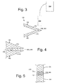
- the wind turbine blade thermographic inspection system 250 may include an infrared camera 260 and the like as is shown in Figs. 3 and 4 .
- An example of an infrared camera 260 capable of providing the thermal images herein may be offered by FLIR Systems, by Fluke Corporation, by Omega Engineering, and by other entities. Any type of heat imaging and/or sensing device may be used herein.
- the thermal images produced by the infrared camera 260 may be processed by different types of software and/or algorithms to ensure overall compliance with predetermined parameters and the like. Other components and other configurations may be used herein.
- the wind turbine blade 100 may be assembled as described above with the exothermic adhesive forming the bond joint 240 between the shells 150, 190.
- heat may be released in a known manner. This heat may be visualized via the infrared camera 260 or other type of heat imaging device of the wind turbine blade thermographic inspection system 250.
- the wind turbine blade thermographic inspection system 250 thus may ensure the integrity of the bond joint 240.
- the wind turbine blade thermographic inspection system 250 may verify the width of the bond joint 240 at the leading edge 160, 200, the trailing edge 170, 210, and elsewhere as is shown in Fig. 5 . These areas are often obscured by the foam, balsa, or other types of core materials that typically do not pass ultrasonic frequencies therethrough.
- the use of the exothermic adhesive 230 has the benefit of positioning a heat source exactly at the area of interest without the influence of an operator. The amount of heat generated must be controlled so as to avoid damage to the materials involved. The exothermic reaction provided by the exothermic adhesive 230 thus reduces the potential for an operator to overheat the area of interest.
- the use of the wind turbine blade 100 and the wind turbine blade thermographic inspection system 250 provides a rapid and low cost inspection system with increased overall reliability and repeatability. Moreover, the inspection may be carried out in the field for "in situ" repairs where other types of testing may not be feasible.
Landscapes
- Chemical & Material Sciences (AREA)
- Engineering & Computer Science (AREA)
- Immunology (AREA)
- Pathology (AREA)
- Analytical Chemistry (AREA)
- Biochemistry (AREA)
- General Health & Medical Sciences (AREA)
- General Physics & Mathematics (AREA)
- Physics & Mathematics (AREA)
- Life Sciences & Earth Sciences (AREA)
- Health & Medical Sciences (AREA)
- Chemical Kinetics & Catalysis (AREA)
- Combustion & Propulsion (AREA)
- Mechanical Engineering (AREA)
- General Engineering & Computer Science (AREA)
- Wind Motors (AREA)
- Investigating Or Analyzing Materials Using Thermal Means (AREA)
- Adhesives Or Adhesive Processes (AREA)
Abstract
Description
- The present application relates generally to wind turbine blades and inspection systems thereof and more particularly relate to a thermographic inspection system for a composite wind turbine blade bond joint using an exothermic adhesive.
- Modem wind turbine blades generally combine low weight and low rotational inertia with high rigidity and high resistance to fatigue and wear so as to withstand the various forces and the extreme conditions encountered over a typical life cycle. Generally described, the turbine blades may be formed from two shell halves. A critical step in the manufacture of the turbine blade is the closing of the two shell halves of the blade at a leading edge, a trailing edge, and at a spar cap union with a shear web via an adhesive to create a bond joint. Verifying the width and the overall integrity of this adhesive bond is required to ensure that the turbine blade will meet performance and lifetime requirements. Failure of the turbine blade along the bond joint could lead to significant damage.
- Current methods for the inspection of this adhesive bond joint include visual inspection and various types of non-destructive imaging inspection techniques such as ultrasonic testing. Such ultrasonic testing, however, may be time consuming and relatively costly. Moreover, some of the blade materials may be difficult to penetrate via ultrasound. Specifically, certain areas of the blade may be obscured from ultrasonic testing because of the use of foam, balsa, or other types of core materials that may not pass typical ultrasonic frequencies therethrough. Certain types of microwave inspection techniques also are known. Such microwave inspection, however, may be limited by exposure to radiation.
- There is thus a desire for improved systems and methods of inspecting an adhesive bond joining the halves of a wind turbine blade. Preferably such systems and methods may accurately and reliably inspect the entire adhesive bond joint without requiring expensive and time consuming ultrasonic testing and the like.
- In one aspect, the present application thus provides a method of inspecting a bond joint. The method may include the steps of applying an exothermic adhesive to a first shell and/or a second shell, attaching the first shell to the second shell via the exothermic adhesive to create the bond joint, allowing the exothermic adhesive to cure, and imaging the heat released by the exothermic adhesive along the bond joint. The bond joint may be a turbine blade bond joint.
- The present application further provides a turbine blade inspection system. The turbine blade inspection system may include a number of turbine blades with a bond joint of an exothermic adhesive and a thermographic device. The thermographic device may image the heat released by the exothermic adhesive to determine the integrity of the bond joint.
- The present application further provides a turbine blade inspection system. The turbine blade inspection system may include a number of turbine blades with a bond joint of an exothermic adhesive about a first shell and a second shell and an infrared camera. The infrared camera may image the heat released by the exothermic adhesive to determine the integrity of the bond joint.
- Various features, improvements and advantages of the present application will become apparent to one of ordinary skill in the art upon review of the following detailed description when taken in conjunction with the several drawings and the appended claims. In the drawings:
-
Fig. 1 is a schematic diagram of a wind turbine blade. -
Fig. 2 is a side sectional view of a portion of the wind turbine blade ofFig. 1 . -
Fig. 3 is a schematic diagram of thermographic inspection system for use with a wind turbine blade having an exothermic adhesive bond joint as may be described herein. -
Fig. 4 is an expanded view of the wind turbine blade ofFig. 3 with the exothermic adhesive bond joint. -
Fig. 5 is a further expanded view of the wind turbine blade ofFig. 3 with the exothermic adhesive bond joint. - Referring now to the drawings, in which like numerals refer to like elements throughout the several views,
Figs. 1 and 2 show awind turbine blade 100 as may be described herein. Generally described, thewind turbine blade 100 may be constructed of layers of an outer skin supported by a primary spar. Specifically, thewind turbine blade 100 may extend from atip 110 to anopposing root 120. Extending between thetip 110 and theroot 120 may be aspar cap 130 and ashear web 140. Theshear web 140 may serve as the main structural support within thewind turbine blade 100. Thespar cap 130 may be a glass portion running the length of thewind turbine blade 100 coincident with theshear web 140 so as to accommodate the tensile load on thewind turbine blade 100. Thewind turbine blade 100 and the components thereof may have any size, shape, or configuration. Other components and other configurations also may be used herein. - As described above, the
wind turbine blade 100 may be formed in shells. For example, afirst shell 150 may extend from a firstshell leading edge 160 to a firstshell trailing ledge 170 and may define asuction surface 180. Thefirst shell 150 may be bonded to asecond shell 190. Thesecond shell 190 may extend from a secondshell leading edge 200 to a secondshell trailing edge 210 and may define apressure surface 220. Theshells shells - In this example, the
shells shells - A
defect 245 in the bond joint 240 formed by the exothermic adhesive 230 may have an impact on the overall operation and lifetime of thewind turbine blade 100. Areas of concern for such a defect include the leadingedges trailing edges 70, 210; and about thespar cap 130. Each of these areas carries at least a portion of the tensile load on theblade 100 such that any bending of the fibers in these areas may reduce the strength of the fiber. - The
wind turbine blade 100 thus may be inspected via a wind turbine bladethermographic inspection system 250 as may be described herein. The wind turbine bladethermographic inspection system 250 may be a type of non-destructive testing using thermography. Specifically, the wind turbine bladethermographic inspection system 250 may include aninfrared camera 260 and the like as is shown inFigs. 3 and 4 . An example of aninfrared camera 260 capable of providing the thermal images herein may be offered by FLIR Systems, by Fluke Corporation, by Omega Engineering, and by other entities. Any type of heat imaging and/or sensing device may be used herein. In addition to visual inspection of the thermal images, the thermal images produced by theinfrared camera 260 may be processed by different types of software and/or algorithms to ensure overall compliance with predetermined parameters and the like. Other components and other configurations may be used herein. - In use, the
wind turbine blade 100 may be assembled as described above with the exothermic adhesive forming the bond joint 240 between theshells infrared camera 260 or other type of heat imaging device of the wind turbine bladethermographic inspection system 250. The wind turbine bladethermographic inspection system 250 thus may ensure the integrity of the bond joint 240. Moreover, the wind turbine bladethermographic inspection system 250 may verify the width of the bond joint 240 at theleading edge edge Fig. 5 . These areas are often obscured by the foam, balsa, or other types of core materials that typically do not pass ultrasonic frequencies therethrough. - Further, the use of the exothermic adhesive 230 has the benefit of positioning a heat source exactly at the area of interest without the influence of an operator. The amount of heat generated must be controlled so as to avoid damage to the materials involved. The exothermic reaction provided by the exothermic adhesive 230 thus reduces the potential for an operator to overheat the area of interest. Specifically, the use of the
wind turbine blade 100 and the wind turbine bladethermographic inspection system 250 provides a rapid and low cost inspection system with increased overall reliability and repeatability. Moreover, the inspection may be carried out in the field for "in situ" repairs where other types of testing may not be feasible. - Although the use of the exothermic adhesive 230 and the wind turbine blade
thermographic inspection system 250 has been discussed in the context of the turbine blade bond joint 240 many other types of bond joints may be inspected herein. Any connection or bonding of two components may be evaluated herein. - It should be apparent that the foregoing relates only to certain embodiments of the present application. Numerous changes and modifications may be made herein by one of ordinary skill in the art without departing from the general spirit and scope of the invention as defined by the following claims and the equivalents thereof.
- Various aspects and embodiments of the present invention are defined by the following numbered clauses:
- 1. A method of inspecting a bond joint, comprising:
- applying an exothermic adhesive to a first shell and/or a second shell;
- attaching the first shell to the second shell via the exothermic adhesive to create the bond joint;
- allowing the exothermic adhesive to cure; and
- imaging the heat released by the exothermic adhesive along the bond joint.
- 2. The method of clause 1, wherein the bond joint comprise a turbine blade bond joint and wherein the step of applying an exothermic adhesive to a first shell and/or a second shell comprises applying an exothermic adhesive to a first turbine blade shell and/or a second turbine blade shell.
- 3. The method of any preceding clause, wherein the step of attaching the first shell to the second shell comprises attaching the first turbine blade shell to the second turbine blade shell.
- 4. The method of any preceding clause, wherein the step of attaching the first turbine blade shell to the second turbine blade shell comprises attaching a first shell leading edge to a second shell leading edge and attaching a first shell trailing edge to a second shell trailing edge.
- 5. The method of any preceding clause, wherein the step of attaching the first turbine blade shell to the second turbine blade shell comprises attaching a spar cap and a shear web.
- 6. The method of any preceding clause, wherein the step of imaging the heat released by the exothermic adhesive comprises imaging the heat released by the exothermic adhesive by an infrared camera.
- 7. The method of any preceding clause, wherein the step of imaging the heat released by the exothermic adhesive comprises maneuvering the infrared camera along the bond joint.
- 8. The method of any preceding clause, wherein the step of imaging the heat released by the exothermic adhesive comprises imaging a defect in the bond joint.
- 9. The method of any preceding clause, wherein the step of imaging the heat released by the exothermic adhesive comprises imaging a width of the bond joint.
- 10. A turbine blade inspection system, comprising:
- a plurality of turbine blades;
- the plurality of turbine blades comprising a bond joint;
- the bond joint comprising an exothermic adhesive; and
- a thermographic device;
- wherein the thermographic device images the heat released by the exothermic adhesive to determine the integrity of the bond joint.
- 11. The turbine blade inspection system of any preceding clause, wherein the plurality of turbine blades comprises a first shell and a second shell joined at the bond joint.
- 12. The turbine blade inspection system of any preceding clause, wherein the plurality of turbine blades comprises a spar cap and a shear web joined at the bond joint.
- 13. The turbine blade inspection system of any preceding clause, wherein the exothermic adhesive comprises a methyl methacrylate monomer, a cyanoacrylate, or a two-part epoxy.
- 14. The turbine blade inspection system of any preceding clause, wherein the thermographic device comprises an infrared camera.
- 15. The turbine blade inspection system of any preceding clause, wherein the plurality of turbine blades is selected from the group consisting of a composite material, a fiber-resin matrix, and a core material.
- 16. A turbine blade inspection system, comprising:
- a plurality of turbine blades;
- the plurality of turbine blades comprising a bond joint about a first shell and a second shell;
- the bond joint comprising an exothermic adhesive; and
- an infrared camera;
- wherein the infrared camera images the heat released by the exothermic adhesive to determine the integrity of the bond joint.
- 17. The turbine blade inspection system of any preceding clause, wherein the plurality of turbine blades comprises a spar cap and a shear web joined at the bond joint.
- 18. The turbine blade inspection system of any preceding clause, wherein the exothermic adhesive comprises a methyl methacrylate monomer, a cyanoacrylate, or a two-part epoxy.
- 19. The turbine blade inspection system of any preceding clause, wherein the plurality of turbine blades comprises a composite material.
- 20. The turbine blade inspection system of any preceding clause, wherein the plurality of turbine blades comprises a fiber-resin matrix and a core material.
Claims (15)
- A method of inspecting a bond joint (240), comprising:applying an exothermic adhesive (230) to a first shell (150) and/or a second shell (190);attaching the first shell (150) to the second shell (190) via the exothermic adhesive (230) to create the bond joint (240);allowing the exothermic adhesive (230) to cure; andimaging the heat released by the exothermic adhesive (230) along the bond joint (240).
- The method of claim 1, wherein the bond joint (240) comprises a turbine blade (100) bond joint (240) and wherein the step of applying an exothermic adhesive (230) to a first shell (150) and/or a second shell (190) comprises applying an exothermic adhesive (230) to a first turbine blade shell and/or a second turbine blade shell.
- The method of any preceding claim, wherein the step of attaching the first shell (150) to the second shell (190) comprises attaching the first turbine blade shell to the second turbine blade shell.
- The method of any preceding claim, wherein the step of attaching the first turbine blade shell to the second turbine blade shell comprises attaching a first shell leading edge (160) to a second shell leading edge (200) and attaching a first shell trailing edge (170) to a second shell trailing edge (210).
- The method of any preceding claim, wherein the step of attaching the first turbine blade shell to the second turbine blade shell comprises attaching a spar cap (130) and a shear web (140).
- The method of any preceding claim, wherein the step of imaging the heat released by the exothermic adhesive (230) comprises imaging the heat released by the exothermic adhesive (230) by an infrared camera (260).
- The method of claim 6, wherein the step of imaging the heat released by the exothermic adhesive (230) comprises maneuvering the infrared camera (260) along the bond joint (240).
- The method of any preceding claim, wherein the step of imaging the heat released by the exothermic adhesive (230) comprises imaging a defect in the bond joint (240).
- The method of any preceding claim, wherein the step of imaging the heat released by the exothermic adhesive (230) comprises imaging a width (270) of the bond joint (240).
- A turbine blade inspection system (250), comprising:a plurality of turbine blades (100);the plurality of turbine blades (100) comprising a bond joint (240);the bond joint (240) comprising an exothermic adhesive (230); anda thermographic device;wherein the thermographic device images the heat released by the exothermic adhesive (230) to determine the integrity of the bond joint (240).
- The turbine blade inspection system (250) of claim 10, wherein the plurality of turbine blades (100) comprises a first shell (150) and a second shell (190) joined at the bond joint (240).
- The turbine blade inspection system (250) of claim 10 or claim 11, wherein the plurality of turbine blades (100) comprises a spar cap (130) and a shear web (140) joined at the bond joint (240).
- The turbine blade inspection system (250) of any of claims 10 to 12, wherein the exothermic adhesive (230) comprises a methyl methacrylate monomer, a cyanoacrylate, or a two-part epoxy.
- The turbine blade inspection system (250) of any of claims 10 to 13, wherein the thermographic device comprises an infrared camera (260).
- The turbine blade inspection system (250) of any of claims 10 to 14, wherein the plurality of turbine blades (100) is selected from the group consisting of a composite material, a fiber-resin matrix, and a core material.
Priority Applications (1)
| Application Number | Priority Date | Filing Date | Title |
|---|---|---|---|
| PL14170741T PL2811289T3 (en) | 2013-06-05 | 2014-06-02 | Thermographic inspection system for composite wind turbine blade |
Applications Claiming Priority (1)
| Application Number | Priority Date | Filing Date | Title |
|---|---|---|---|
| US13/910,178 US9689262B2 (en) | 2013-06-05 | 2013-06-05 | Thermographic inspection system for composite wind turbine blade |
Publications (2)
| Publication Number | Publication Date |
|---|---|
| EP2811289A1 true EP2811289A1 (en) | 2014-12-10 |
| EP2811289B1 EP2811289B1 (en) | 2020-07-29 |
Family
ID=50932967
Family Applications (1)
| Application Number | Title | Priority Date | Filing Date |
|---|---|---|---|
| EP14170741.4A Active EP2811289B1 (en) | 2013-06-05 | 2014-06-02 | Thermographic inspection system for composite wind turbine blade |
Country Status (8)
| Country | Link |
|---|---|
| US (1) | US9689262B2 (en) |
| EP (1) | EP2811289B1 (en) |
| JP (1) | JP6683412B2 (en) |
| CN (1) | CN104234942B (en) |
| DK (1) | DK2811289T3 (en) |
| ES (1) | ES2828528T3 (en) |
| PL (1) | PL2811289T3 (en) |
| PT (1) | PT2811289T (en) |
Families Citing this family (5)
| Publication number | Priority date | Publication date | Assignee | Title |
|---|---|---|---|---|
| EP3303830B1 (en) * | 2015-05-28 | 2022-09-14 | LM Wind Power A/S | Wind turbine blade with a trailing edge spacing section |
| US11125205B2 (en) * | 2015-09-14 | 2021-09-21 | General Electric Company | Systems and methods for joining blade components of rotor blades |
| US9879989B2 (en) | 2015-12-09 | 2018-01-30 | General Electric Company | Methods and systems for inspecting a wind turbine blade |
| US10641720B2 (en) | 2017-10-06 | 2020-05-05 | General Electric Company | Thermal barrier coating spallation detection system |
| EP4191057A1 (en) * | 2021-12-01 | 2023-06-07 | Siemens Gamesa Renewable Energy A/S | Method of inspecting an adhesive layer |
Citations (3)
| Publication number | Priority date | Publication date | Assignee | Title |
|---|---|---|---|---|
| WO2003069324A1 (en) * | 2002-02-15 | 2003-08-21 | Lm Glasfiber A/S | A method and an apparatus for the detection of the presence of polymer in a wind turbine blade |
| US20120033207A1 (en) * | 2011-07-28 | 2012-02-09 | General Electric Company | Composite fiber wave inspection system and method |
| US20130306217A1 (en) * | 2012-05-18 | 2013-11-21 | GM Global Technology Operations LLC | Inspection method for wheel cladding |
Family Cites Families (22)
| Publication number | Priority date | Publication date | Assignee | Title |
|---|---|---|---|---|
| US3480492A (en) | 1967-02-20 | 1969-11-25 | Branson Instr | Method of bonding using exothermic adhesive activated by ultrasonic energy |
| JPS58213243A (en) * | 1982-06-07 | 1983-12-12 | Nippon Telegr & Teleph Corp <Ntt> | Detection of injected quantity of adhesive |
| US6670808B2 (en) | 2001-08-27 | 2003-12-30 | General Electric Company | Self reference eddy current probe, measurement system, and measurement method |
| US6812697B2 (en) | 2002-09-24 | 2004-11-02 | General Electric Company | Molded eddy current array probe |
| US20050169346A1 (en) * | 2004-01-29 | 2005-08-04 | Trw Automotive U.S. Llc | Method for monitoring quality of a transmissive laser weld |
| US7419298B2 (en) * | 2005-05-24 | 2008-09-02 | United Technologies Corporation | Thermal imaging method and apparatus |
| US7516663B2 (en) * | 2006-11-03 | 2009-04-14 | General Electric Company | Systems and method for locating failure events in samples under load |
| US7895745B2 (en) * | 2007-03-09 | 2011-03-01 | General Electric Company | Method for fabricating elongated airfoils for wind turbines |
| US7750643B2 (en) | 2007-10-30 | 2010-07-06 | General Electric Company | Process and system for detecting surface anomalies |
| US20090167024A1 (en) * | 2007-12-28 | 2009-07-02 | Thorsten Landau | Gluing of wind turbine internals to structural components |
| US8393784B2 (en) | 2008-03-31 | 2013-03-12 | General Electric Company | Characterization of flaws in composites identified by thermography |
| US8506159B2 (en) * | 2008-09-17 | 2013-08-13 | Nippon Steel & Sumitomo Metal Corporation | Method for detecting defect in material and system for the method |
| US8378668B2 (en) | 2008-11-29 | 2013-02-19 | General Electric Company | Method for non-destructive testing of composite systems |
| US8235663B2 (en) | 2008-12-11 | 2012-08-07 | General Electric Company | Article and ultrasonic inspection method and system therefor |
| US8281442B2 (en) | 2009-07-17 | 2012-10-09 | General Electric Company | Wind turbine blade inspection and cleaning system |
| US9566754B2 (en) * | 2010-07-08 | 2017-02-14 | Vesta Wind Systems A/S | Turbine blade temperature measurement system and method of manufacture of turbine blades |
| FR2965353B1 (en) * | 2010-09-28 | 2013-08-23 | Astrium Sas | METHOD AND DEVICE FOR NON-DESTRUCTIVE CONTROL OF WINDMILL BLADES |
| US8743196B2 (en) | 2010-12-16 | 2014-06-03 | General Electric Company | System and method for performing an external inspection on a wind turbine rotor blade |
| EP2522994A1 (en) * | 2011-05-13 | 2012-11-14 | General Electric Company | Magnetic inspection systems for inspection of target objects |
| US8706436B2 (en) | 2011-06-03 | 2014-04-22 | General Electric Company | Manufacture of engineering components with designed defects for analysis of production components |
| US20130086991A1 (en) | 2011-10-07 | 2013-04-11 | General Electric Company | Detection process |
| US8806746B2 (en) * | 2011-11-30 | 2014-08-19 | Gamesa Innovation & Technology, S.L. | Method for cleaning wind turbine blades |
-
2013
- 2013-06-05 US US13/910,178 patent/US9689262B2/en active Active
-
2014
- 2014-05-23 JP JP2014106610A patent/JP6683412B2/en active Active
- 2014-06-02 PL PL14170741T patent/PL2811289T3/en unknown
- 2014-06-02 DK DK14170741.4T patent/DK2811289T3/en active
- 2014-06-02 PT PT141707414T patent/PT2811289T/en unknown
- 2014-06-02 ES ES14170741T patent/ES2828528T3/en active Active
- 2014-06-02 EP EP14170741.4A patent/EP2811289B1/en active Active
- 2014-06-05 CN CN201410246708.5A patent/CN104234942B/en active Active
Patent Citations (3)
| Publication number | Priority date | Publication date | Assignee | Title |
|---|---|---|---|---|
| WO2003069324A1 (en) * | 2002-02-15 | 2003-08-21 | Lm Glasfiber A/S | A method and an apparatus for the detection of the presence of polymer in a wind turbine blade |
| US20120033207A1 (en) * | 2011-07-28 | 2012-02-09 | General Electric Company | Composite fiber wave inspection system and method |
| US20130306217A1 (en) * | 2012-05-18 | 2013-11-21 | GM Global Technology Operations LLC | Inspection method for wheel cladding |
Also Published As
| Publication number | Publication date |
|---|---|
| ES2828528T3 (en) | 2021-05-26 |
| CN104234942B (en) | 2019-08-02 |
| JP6683412B2 (en) | 2020-04-22 |
| DK2811289T3 (en) | 2020-11-02 |
| JP2014238393A (en) | 2014-12-18 |
| PL2811289T3 (en) | 2021-01-11 |
| PT2811289T (en) | 2020-10-30 |
| US9689262B2 (en) | 2017-06-27 |
| US20140363294A1 (en) | 2014-12-11 |
| EP2811289B1 (en) | 2020-07-29 |
| CN104234942A (en) | 2014-12-24 |
Similar Documents
| Publication | Publication Date | Title |
|---|---|---|
| EP2811289B1 (en) | Thermographic inspection system for composite wind turbine blade | |
| CN107567380B (en) | Method and system for bonding | |
| JP6450158B2 (en) | Method for identifying processing position in repair material and repair method | |
| EP2808155B1 (en) | Joint assembly and method of assembling the same | |
| US20230415448A1 (en) | Honeycomb core sandwich panels | |
| KR20110065526A (en) | Joint between aircraft members | |
| CN113423948B (en) | Improvements related to wind turbine blade manufacturing | |
| BR112015026520B1 (en) | bonded structure and bond condition detection method | |
| CN116547128A (en) | Wind turbine blade with improved bond joint between shear web and shell | |
| CN113423562B (en) | Improvements relating to wind turbine blade manufacture | |
| EP4504498A1 (en) | Adhesive joint inspection of wind turbine blades | |
| JP6740138B2 (en) | Bonding structure, manufacturing method thereof, and bonding state detecting method | |
| EP3159655A1 (en) | Profilometry inspection systems and methods for spar caps of composite wind turbine blades | |
| RU2574780C2 (en) | Connection set and method of its assembly |
Legal Events
| Date | Code | Title | Description |
|---|---|---|---|
| PUAI | Public reference made under article 153(3) epc to a published international application that has entered the european phase |
Free format text: ORIGINAL CODE: 0009012 |
|
| 17P | Request for examination filed |
Effective date: 20140602 |
|
| AK | Designated contracting states |
Kind code of ref document: A1 Designated state(s): AL AT BE BG CH CY CZ DE DK EE ES FI FR GB GR HR HU IE IS IT LI LT LU LV MC MK MT NL NO PL PT RO RS SE SI SK SM TR |
|
| AX | Request for extension of the european patent |
Extension state: BA ME |
|
| R17P | Request for examination filed (corrected) |
Effective date: 20150610 |
|
| RBV | Designated contracting states (corrected) |
Designated state(s): AL AT BE BG CH CY CZ DE DK EE ES FI FR GB GR HR HU IE IS IT LI LT LU LV MC MK MT NL NO PL PT RO RS SE SI SK SM TR |
|
| STAA | Information on the status of an ep patent application or granted ep patent |
Free format text: STATUS: EXAMINATION IS IN PROGRESS |
|
| 17Q | First examination report despatched |
Effective date: 20180611 |
|
| GRAP | Despatch of communication of intention to grant a patent |
Free format text: ORIGINAL CODE: EPIDOSNIGR1 |
|
| STAA | Information on the status of an ep patent application or granted ep patent |
Free format text: STATUS: GRANT OF PATENT IS INTENDED |
|
| INTG | Intention to grant announced |
Effective date: 20191220 |
|
| GRAS | Grant fee paid |
Free format text: ORIGINAL CODE: EPIDOSNIGR3 |
|
| GRAA | (expected) grant |
Free format text: ORIGINAL CODE: 0009210 |
|
| STAA | Information on the status of an ep patent application or granted ep patent |
Free format text: STATUS: THE PATENT HAS BEEN GRANTED |
|
| AK | Designated contracting states |
Kind code of ref document: B1 Designated state(s): AL AT BE BG CH CY CZ DE DK EE ES FI FR GB GR HR HU IE IS IT LI LT LU LV MC MK MT NL NO PL PT RO RS SE SI SK SM TR |
|
| REG | Reference to a national code |
Ref country code: CH Ref legal event code: EP |
|
| REG | Reference to a national code |
Ref country code: AT Ref legal event code: REF Ref document number: 1296372 Country of ref document: AT Kind code of ref document: T Effective date: 20200815 |
|
| REG | Reference to a national code |
Ref country code: IE Ref legal event code: FG4D |
|
| REG | Reference to a national code |
Ref country code: DE Ref legal event code: R096 Ref document number: 602014068213 Country of ref document: DE |
|
| REG | Reference to a national code |
Ref country code: PT Ref legal event code: SC4A Ref document number: 2811289 Country of ref document: PT Date of ref document: 20201030 Kind code of ref document: T Free format text: AVAILABILITY OF NATIONAL TRANSLATION Effective date: 20201023 |
|
| REG | Reference to a national code |
Ref country code: DK Ref legal event code: T3 Effective date: 20201029 |
|
| REG | Reference to a national code |
Ref country code: LT Ref legal event code: MG4D |
|
| REG | Reference to a national code |
Ref country code: NL Ref legal event code: MP Effective date: 20200729 |
|
| REG | Reference to a national code |
Ref country code: AT Ref legal event code: MK05 Ref document number: 1296372 Country of ref document: AT Kind code of ref document: T Effective date: 20200729 |
|
| PG25 | Lapsed in a contracting state [announced via postgrant information from national office to epo] |
Ref country code: SE Free format text: LAPSE BECAUSE OF FAILURE TO SUBMIT A TRANSLATION OF THE DESCRIPTION OR TO PAY THE FEE WITHIN THE PRESCRIBED TIME-LIMIT Effective date: 20200729 Ref country code: AT Free format text: LAPSE BECAUSE OF FAILURE TO SUBMIT A TRANSLATION OF THE DESCRIPTION OR TO PAY THE FEE WITHIN THE PRESCRIBED TIME-LIMIT Effective date: 20200729 Ref country code: NO Free format text: LAPSE BECAUSE OF FAILURE TO SUBMIT A TRANSLATION OF THE DESCRIPTION OR TO PAY THE FEE WITHIN THE PRESCRIBED TIME-LIMIT Effective date: 20201029 Ref country code: FI Free format text: LAPSE BECAUSE OF FAILURE TO SUBMIT A TRANSLATION OF THE DESCRIPTION OR TO PAY THE FEE WITHIN THE PRESCRIBED TIME-LIMIT Effective date: 20200729 Ref country code: HR Free format text: LAPSE BECAUSE OF FAILURE TO SUBMIT A TRANSLATION OF THE DESCRIPTION OR TO PAY THE FEE WITHIN THE PRESCRIBED TIME-LIMIT Effective date: 20200729 Ref country code: BG Free format text: LAPSE BECAUSE OF FAILURE TO SUBMIT A TRANSLATION OF THE DESCRIPTION OR TO PAY THE FEE WITHIN THE PRESCRIBED TIME-LIMIT Effective date: 20201029 Ref country code: GR Free format text: LAPSE BECAUSE OF FAILURE TO SUBMIT A TRANSLATION OF THE DESCRIPTION OR TO PAY THE FEE WITHIN THE PRESCRIBED TIME-LIMIT Effective date: 20201030 Ref country code: LT Free format text: LAPSE BECAUSE OF FAILURE TO SUBMIT A TRANSLATION OF THE DESCRIPTION OR TO PAY THE FEE WITHIN THE PRESCRIBED TIME-LIMIT Effective date: 20200729 |
|
| PG25 | Lapsed in a contracting state [announced via postgrant information from national office to epo] |
Ref country code: RS Free format text: LAPSE BECAUSE OF FAILURE TO SUBMIT A TRANSLATION OF THE DESCRIPTION OR TO PAY THE FEE WITHIN THE PRESCRIBED TIME-LIMIT Effective date: 20200729 Ref country code: LV Free format text: LAPSE BECAUSE OF FAILURE TO SUBMIT A TRANSLATION OF THE DESCRIPTION OR TO PAY THE FEE WITHIN THE PRESCRIBED TIME-LIMIT Effective date: 20200729 Ref country code: IS Free format text: LAPSE BECAUSE OF FAILURE TO SUBMIT A TRANSLATION OF THE DESCRIPTION OR TO PAY THE FEE WITHIN THE PRESCRIBED TIME-LIMIT Effective date: 20201129 |
|
| PG25 | Lapsed in a contracting state [announced via postgrant information from national office to epo] |
Ref country code: NL Free format text: LAPSE BECAUSE OF FAILURE TO SUBMIT A TRANSLATION OF THE DESCRIPTION OR TO PAY THE FEE WITHIN THE PRESCRIBED TIME-LIMIT Effective date: 20200729 |
|
| PG25 | Lapsed in a contracting state [announced via postgrant information from national office to epo] |
Ref country code: IT Free format text: LAPSE BECAUSE OF FAILURE TO SUBMIT A TRANSLATION OF THE DESCRIPTION OR TO PAY THE FEE WITHIN THE PRESCRIBED TIME-LIMIT Effective date: 20200729 Ref country code: EE Free format text: LAPSE BECAUSE OF FAILURE TO SUBMIT A TRANSLATION OF THE DESCRIPTION OR TO PAY THE FEE WITHIN THE PRESCRIBED TIME-LIMIT Effective date: 20200729 Ref country code: CZ Free format text: LAPSE BECAUSE OF FAILURE TO SUBMIT A TRANSLATION OF THE DESCRIPTION OR TO PAY THE FEE WITHIN THE PRESCRIBED TIME-LIMIT Effective date: 20200729 Ref country code: RO Free format text: LAPSE BECAUSE OF FAILURE TO SUBMIT A TRANSLATION OF THE DESCRIPTION OR TO PAY THE FEE WITHIN THE PRESCRIBED TIME-LIMIT Effective date: 20200729 Ref country code: SM Free format text: LAPSE BECAUSE OF FAILURE TO SUBMIT A TRANSLATION OF THE DESCRIPTION OR TO PAY THE FEE WITHIN THE PRESCRIBED TIME-LIMIT Effective date: 20200729 |
|
| REG | Reference to a national code |
Ref country code: DE Ref legal event code: R097 Ref document number: 602014068213 Country of ref document: DE |
|
| REG | Reference to a national code |
Ref country code: ES Ref legal event code: FG2A Ref document number: 2828528 Country of ref document: ES Kind code of ref document: T3 Effective date: 20210526 |
|
| PG25 | Lapsed in a contracting state [announced via postgrant information from national office to epo] |
Ref country code: AL Free format text: LAPSE BECAUSE OF FAILURE TO SUBMIT A TRANSLATION OF THE DESCRIPTION OR TO PAY THE FEE WITHIN THE PRESCRIBED TIME-LIMIT Effective date: 20200729 |
|
| PLBE | No opposition filed within time limit |
Free format text: ORIGINAL CODE: 0009261 |
|
| STAA | Information on the status of an ep patent application or granted ep patent |
Free format text: STATUS: NO OPPOSITION FILED WITHIN TIME LIMIT |
|
| PG25 | Lapsed in a contracting state [announced via postgrant information from national office to epo] |
Ref country code: SK Free format text: LAPSE BECAUSE OF FAILURE TO SUBMIT A TRANSLATION OF THE DESCRIPTION OR TO PAY THE FEE WITHIN THE PRESCRIBED TIME-LIMIT Effective date: 20200729 |
|
| 26N | No opposition filed |
Effective date: 20210430 |
|
| PG25 | Lapsed in a contracting state [announced via postgrant information from national office to epo] |
Ref country code: SI Free format text: LAPSE BECAUSE OF FAILURE TO SUBMIT A TRANSLATION OF THE DESCRIPTION OR TO PAY THE FEE WITHIN THE PRESCRIBED TIME-LIMIT Effective date: 20200729 |
|
| PG25 | Lapsed in a contracting state [announced via postgrant information from national office to epo] |
Ref country code: MC Free format text: LAPSE BECAUSE OF FAILURE TO SUBMIT A TRANSLATION OF THE DESCRIPTION OR TO PAY THE FEE WITHIN THE PRESCRIBED TIME-LIMIT Effective date: 20200729 |
|
| REG | Reference to a national code |
Ref country code: CH Ref legal event code: PL |
|
| REG | Reference to a national code |
Ref country code: BE Ref legal event code: MM Effective date: 20210630 |
|
| PG25 | Lapsed in a contracting state [announced via postgrant information from national office to epo] |
Ref country code: LU Free format text: LAPSE BECAUSE OF NON-PAYMENT OF DUE FEES Effective date: 20210602 |
|
| PG25 | Lapsed in a contracting state [announced via postgrant information from national office to epo] |
Ref country code: LI Free format text: LAPSE BECAUSE OF NON-PAYMENT OF DUE FEES Effective date: 20210630 Ref country code: IE Free format text: LAPSE BECAUSE OF NON-PAYMENT OF DUE FEES Effective date: 20210602 Ref country code: CH Free format text: LAPSE BECAUSE OF NON-PAYMENT OF DUE FEES Effective date: 20210630 |
|
| PG25 | Lapsed in a contracting state [announced via postgrant information from national office to epo] |
Ref country code: BE Free format text: LAPSE BECAUSE OF NON-PAYMENT OF DUE FEES Effective date: 20210630 |
|
| PG25 | Lapsed in a contracting state [announced via postgrant information from national office to epo] |
Ref country code: HU Free format text: LAPSE BECAUSE OF FAILURE TO SUBMIT A TRANSLATION OF THE DESCRIPTION OR TO PAY THE FEE WITHIN THE PRESCRIBED TIME-LIMIT; INVALID AB INITIO Effective date: 20140602 |
|
| P01 | Opt-out of the competence of the unified patent court (upc) registered |
Effective date: 20230522 |
|
| PG25 | Lapsed in a contracting state [announced via postgrant information from national office to epo] |
Ref country code: CY Free format text: LAPSE BECAUSE OF FAILURE TO SUBMIT A TRANSLATION OF THE DESCRIPTION OR TO PAY THE FEE WITHIN THE PRESCRIBED TIME-LIMIT Effective date: 20200729 |
|
| REG | Reference to a national code |
Ref country code: GB Ref legal event code: 732E Free format text: REGISTERED BETWEEN 20231123 AND 20231129 |
|
| REG | Reference to a national code |
Ref country code: DE Ref legal event code: R081 Ref document number: 602014068213 Country of ref document: DE Owner name: GENERAL ELECTRIC RENOVABLES ESPANA S.L., ES Free format text: FORMER OWNER: GENERAL ELECTRIC COMPANY, SCHENECTADY, NY, US Ref country code: DE Ref legal event code: R081 Ref document number: 602014068213 Country of ref document: DE Owner name: LM WIND POWER A/S, DK Free format text: FORMER OWNER: GENERAL ELECTRIC COMPANY, SCHENECTADY, NY, US Ref country code: DE Ref legal event code: R082 Ref document number: 602014068213 Country of ref document: DE Ref country code: DE Ref legal event code: R082 Ref document number: 602014068213 Country of ref document: DE Representative=s name: ZIMMERMANN & PARTNER PATENTANWAELTE MBB, DE |
|
| REG | Reference to a national code |
Ref country code: DE Ref legal event code: R082 Ref document number: 602014068213 Country of ref document: DE Representative=s name: ZIMMERMANN & PARTNER PATENTANWAELTE MBB, DE |
|
| PG25 | Lapsed in a contracting state [announced via postgrant information from national office to epo] |
Ref country code: MK Free format text: LAPSE BECAUSE OF FAILURE TO SUBMIT A TRANSLATION OF THE DESCRIPTION OR TO PAY THE FEE WITHIN THE PRESCRIBED TIME-LIMIT Effective date: 20200729 |
|
| PGFP | Annual fee paid to national office [announced via postgrant information from national office to epo] |
Ref country code: PT Payment date: 20240521 Year of fee payment: 11 |
|
| REG | Reference to a national code |
Ref country code: ES Ref legal event code: PC2A Owner name: LM WIND POWER A/S Effective date: 20240820 |
|
| PG25 | Lapsed in a contracting state [announced via postgrant information from national office to epo] |
Ref country code: MT Free format text: LAPSE BECAUSE OF FAILURE TO SUBMIT A TRANSLATION OF THE DESCRIPTION OR TO PAY THE FEE WITHIN THE PRESCRIBED TIME-LIMIT Effective date: 20200729 |
|
| REG | Reference to a national code |
Ref country code: ES Ref legal event code: PC2A Owner name: GENERAL ELECTRIC RENOVABLES ESPANA, S.L. Effective date: 20241015 |
|
| REG | Reference to a national code |
Ref country code: DE Ref legal event code: R082 Ref document number: 602014068213 Country of ref document: DE Ref country code: DE Ref legal event code: R081 Ref document number: 602014068213 Country of ref document: DE Owner name: GENERAL ELECTRIC RENOVABLES ESPANA S.L., ES Free format text: FORMER OWNER: LM WIND POWER A/S, KOLDING, DK |
|
| REG | Reference to a national code |
Ref country code: GB Ref legal event code: 732E Free format text: REGISTERED BETWEEN 20241003 AND 20241009 |
|
| PGFP | Annual fee paid to national office [announced via postgrant information from national office to epo] |
Ref country code: PL Payment date: 20250520 Year of fee payment: 12 Ref country code: DE Payment date: 20250520 Year of fee payment: 12 |
|
| PGFP | Annual fee paid to national office [announced via postgrant information from national office to epo] |
Ref country code: GB Payment date: 20250520 Year of fee payment: 12 Ref country code: DK Payment date: 20250520 Year of fee payment: 12 |
|
| PGFP | Annual fee paid to national office [announced via postgrant information from national office to epo] |
Ref country code: FR Payment date: 20250520 Year of fee payment: 12 |
|
| PGFP | Annual fee paid to national office [announced via postgrant information from national office to epo] |
Ref country code: TR Payment date: 20250526 Year of fee payment: 12 |
|
| PGFP | Annual fee paid to national office [announced via postgrant information from national office to epo] |
Ref country code: ES Payment date: 20250701 Year of fee payment: 12 |
|
| PG25 | Lapsed in a contracting state [announced via postgrant information from national office to epo] |
Ref country code: PT Free format text: LAPSE BECAUSE OF NON-PAYMENT OF DUE FEES Effective date: 20251202 |