EP2811212A1 - Resin hose and method for producing same - Google Patents
Resin hose and method for producing same Download PDFInfo
- Publication number
- EP2811212A1 EP2811212A1 EP12867529.5A EP12867529A EP2811212A1 EP 2811212 A1 EP2811212 A1 EP 2811212A1 EP 12867529 A EP12867529 A EP 12867529A EP 2811212 A1 EP2811212 A1 EP 2811212A1
- Authority
- EP
- European Patent Office
- Prior art keywords
- hose
- needle
- resin
- polyamide
- island phases
- Prior art date
- Legal status (The legal status is an assumption and is not a legal conclusion. Google has not performed a legal analysis and makes no representation as to the accuracy of the status listed.)
- Withdrawn
Links
- 229920005989 resin Polymers 0.000 title claims abstract description 54
- 239000011347 resin Substances 0.000 title claims abstract description 54
- 238000004519 manufacturing process Methods 0.000 title 1
- 229920006012 semi-aromatic polyamide Polymers 0.000 claims abstract description 27
- 239000004953 Aliphatic polyamide Substances 0.000 claims abstract description 25
- 229920003231 aliphatic polyamide Polymers 0.000 claims abstract description 25
- RDOFJDLLWVCMRU-UHFFFAOYSA-N Diisobutyl adipate Chemical compound CC(C)COC(=O)CCCCC(=O)OCC(C)C RDOFJDLLWVCMRU-UHFFFAOYSA-N 0.000 claims abstract description 15
- 229940031769 diisobutyl adipate Drugs 0.000 claims abstract description 15
- 238000001125 extrusion Methods 0.000 claims description 22
- 238000000034 method Methods 0.000 claims description 10
- 238000010008 shearing Methods 0.000 claims description 2
- 239000000446 fuel Substances 0.000 abstract description 31
- 230000004888 barrier function Effects 0.000 abstract description 26
- 239000010410 layer Substances 0.000 description 24
- 230000002093 peripheral effect Effects 0.000 description 12
- 239000011342 resin composition Substances 0.000 description 11
- 239000004952 Polyamide Substances 0.000 description 7
- 238000011156 evaluation Methods 0.000 description 7
- 229920002647 polyamide Polymers 0.000 description 7
- 239000004609 Impact Modifier Substances 0.000 description 6
- 230000000052 comparative effect Effects 0.000 description 6
- 229920001971 elastomer Polymers 0.000 description 6
- 239000004014 plasticizer Substances 0.000 description 6
- 239000002356 single layer Substances 0.000 description 6
- LFQSCWFLJHTTHZ-UHFFFAOYSA-N Ethanol Chemical compound CCO LFQSCWFLJHTTHZ-UHFFFAOYSA-N 0.000 description 4
- IPRJXAGUEGOFGG-UHFFFAOYSA-N N-butylbenzenesulfonamide Chemical compound CCCCNS(=O)(=O)C1=CC=CC=C1 IPRJXAGUEGOFGG-UHFFFAOYSA-N 0.000 description 4
- 229920000572 Nylon 6/12 Polymers 0.000 description 4
- 239000000806 elastomer Substances 0.000 description 4
- 229920002292 Nylon 6 Polymers 0.000 description 3
- YXFVVABEGXRONW-UHFFFAOYSA-N Toluene Chemical compound CC1=CC=CC=C1 YXFVVABEGXRONW-UHFFFAOYSA-N 0.000 description 3
- 239000003795 chemical substances by application Substances 0.000 description 3
- 229920001577 copolymer Polymers 0.000 description 3
- 238000009792 diffusion process Methods 0.000 description 3
- 239000000463 material Substances 0.000 description 3
- 238000002156 mixing Methods 0.000 description 3
- 239000000203 mixture Substances 0.000 description 3
- 239000000126 substance Substances 0.000 description 3
- 229920000299 Nylon 12 Polymers 0.000 description 2
- 229920002302 Nylon 6,6 Polymers 0.000 description 2
- 229920006154 PA11T Polymers 0.000 description 2
- 229920006155 PA13T Polymers 0.000 description 2
- 229920006153 PA4T Polymers 0.000 description 2
- MSZJEPVVQWJCIF-UHFFFAOYSA-N butylazanide Chemical compound CCCC[NH-] MSZJEPVVQWJCIF-UHFFFAOYSA-N 0.000 description 2
- 150000001875 compounds Chemical class 0.000 description 2
- JOXIMZWYDAKGHI-UHFFFAOYSA-N p-toluenesulfonic acid Substances CC1=CC=C(S(O)(=O)=O)C=C1 JOXIMZWYDAKGHI-UHFFFAOYSA-N 0.000 description 2
- 229920006111 poly(hexamethylene terephthalamide) Polymers 0.000 description 2
- 229920006128 poly(nonamethylene terephthalamide) Polymers 0.000 description 2
- 230000003014 reinforcing effect Effects 0.000 description 2
- LTHNHFOGQMKPOV-UHFFFAOYSA-N 2-ethylhexan-1-amine Chemical compound CCCCC(CC)CN LTHNHFOGQMKPOV-UHFFFAOYSA-N 0.000 description 1
- FGTLUYQJKVPUHM-UHFFFAOYSA-N 4-methyl-n-propylbenzenesulfonamide Chemical compound CCCNS(=O)(=O)C1=CC=C(C)C=C1 FGTLUYQJKVPUHM-UHFFFAOYSA-N 0.000 description 1
- NHTMVDHEPJAVLT-UHFFFAOYSA-N Isooctane Chemical compound CC(C)CC(C)(C)C NHTMVDHEPJAVLT-UHFFFAOYSA-N 0.000 description 1
- AFCARXCZXQIEQB-UHFFFAOYSA-N N-[3-oxo-3-(2,4,6,7-tetrahydrotriazolo[4,5-c]pyridin-5-yl)propyl]-2-[[3-(trifluoromethoxy)phenyl]methylamino]pyrimidine-5-carboxamide Chemical compound O=C(CCNC(=O)C=1C=NC(=NC=1)NCC1=CC(=CC=C1)OC(F)(F)F)N1CC2=C(CC1)NN=N2 AFCARXCZXQIEQB-UHFFFAOYSA-N 0.000 description 1
- 229920000459 Nitrile rubber Polymers 0.000 description 1
- 229920000571 Nylon 11 Polymers 0.000 description 1
- 229920003189 Nylon 4,6 Polymers 0.000 description 1
- 229920000305 Nylon 6,10 Polymers 0.000 description 1
- 229920000577 Nylon 6/66 Polymers 0.000 description 1
- 229920012310 Polyamide 9T (PA9T) Polymers 0.000 description 1
- 229920002614 Polyether block amide Polymers 0.000 description 1
- 239000004721 Polyphenylene oxide Substances 0.000 description 1
- 229920006121 Polyxylylene adipamide Polymers 0.000 description 1
- 229910000831 Steel Inorganic materials 0.000 description 1
- 230000006750 UV protection Effects 0.000 description 1
- 229920000800 acrylic rubber Polymers 0.000 description 1
- 230000000655 anti-hydrolysis Effects 0.000 description 1
- 230000003064 anti-oxidating effect Effects 0.000 description 1
- 239000003963 antioxidant agent Substances 0.000 description 1
- 230000003078 antioxidant effect Effects 0.000 description 1
- 230000005540 biological transmission Effects 0.000 description 1
- 229920005549 butyl rubber Polymers 0.000 description 1
- 239000000470 constituent Substances 0.000 description 1
- 238000010276 construction Methods 0.000 description 1
- 238000001816 cooling Methods 0.000 description 1
- JVSWJIKNEAIKJW-UHFFFAOYSA-N dimethyl-hexane Natural products CCCCCC(C)C JVSWJIKNEAIKJW-UHFFFAOYSA-N 0.000 description 1
- 230000000694 effects Effects 0.000 description 1
- 150000002148 esters Chemical class 0.000 description 1
- HQQADJVZYDDRJT-UHFFFAOYSA-N ethene;prop-1-ene Chemical group C=C.CC=C HQQADJVZYDDRJT-UHFFFAOYSA-N 0.000 description 1
- 239000000945 filler Substances 0.000 description 1
- 229920001973 fluoroelastomer Polymers 0.000 description 1
- 230000007062 hydrolysis Effects 0.000 description 1
- 238000006460 hydrolysis reaction Methods 0.000 description 1
- 230000002401 inhibitory effect Effects 0.000 description 1
- 229920000554 ionomer Polymers 0.000 description 1
- 238000004898 kneading Methods 0.000 description 1
- 239000007788 liquid Substances 0.000 description 1
- 239000000314 lubricant Substances 0.000 description 1
- 238000005259 measurement Methods 0.000 description 1
- 238000002844 melting Methods 0.000 description 1
- 230000008018 melting Effects 0.000 description 1
- 238000012986 modification Methods 0.000 description 1
- 230000004048 modification Effects 0.000 description 1
- 239000002667 nucleating agent Substances 0.000 description 1
- VNAXUESFTGIAPD-UHFFFAOYSA-N octan-3-yl 4-methylbenzenesulfonate Chemical compound CCCCCC(CC)OS(=O)(=O)C1=CC=C(C)C=C1 VNAXUESFTGIAPD-UHFFFAOYSA-N 0.000 description 1
- 230000035699 permeability Effects 0.000 description 1
- 229920000058 polyacrylate Polymers 0.000 description 1
- 229920006149 polyester-amide block copolymer Polymers 0.000 description 1
- 229920000570 polyether Polymers 0.000 description 1
- 229920006146 polyetheresteramide block copolymer Polymers 0.000 description 1
- 229920000098 polyolefin Polymers 0.000 description 1
- 239000011814 protection agent Substances 0.000 description 1
- 229920002379 silicone rubber Polymers 0.000 description 1
- 239000004945 silicone rubber Substances 0.000 description 1
- 239000010959 steel Substances 0.000 description 1
- 238000012360 testing method Methods 0.000 description 1
- XLYOFNOQVPJJNP-UHFFFAOYSA-N water Substances O XLYOFNOQVPJJNP-UHFFFAOYSA-N 0.000 description 1
Images
Classifications
-
- B—PERFORMING OPERATIONS; TRANSPORTING
- B29—WORKING OF PLASTICS; WORKING OF SUBSTANCES IN A PLASTIC STATE IN GENERAL
- B29C—SHAPING OR JOINING OF PLASTICS; SHAPING OF MATERIAL IN A PLASTIC STATE, NOT OTHERWISE PROVIDED FOR; AFTER-TREATMENT OF THE SHAPED PRODUCTS, e.g. REPAIRING
- B29C48/00—Extrusion moulding, i.e. expressing the moulding material through a die or nozzle which imparts the desired form; Apparatus therefor
- B29C48/022—Extrusion moulding, i.e. expressing the moulding material through a die or nozzle which imparts the desired form; Apparatus therefor characterised by the choice of material
-
- B—PERFORMING OPERATIONS; TRANSPORTING
- B29—WORKING OF PLASTICS; WORKING OF SUBSTANCES IN A PLASTIC STATE IN GENERAL
- B29C—SHAPING OR JOINING OF PLASTICS; SHAPING OF MATERIAL IN A PLASTIC STATE, NOT OTHERWISE PROVIDED FOR; AFTER-TREATMENT OF THE SHAPED PRODUCTS, e.g. REPAIRING
- B29C48/00—Extrusion moulding, i.e. expressing the moulding material through a die or nozzle which imparts the desired form; Apparatus therefor
- B29C48/03—Extrusion moulding, i.e. expressing the moulding material through a die or nozzle which imparts the desired form; Apparatus therefor characterised by the shape of the extruded material at extrusion
- B29C48/09—Articles with cross-sections having partially or fully enclosed cavities, e.g. pipes or channels
-
- B—PERFORMING OPERATIONS; TRANSPORTING
- B29—WORKING OF PLASTICS; WORKING OF SUBSTANCES IN A PLASTIC STATE IN GENERAL
- B29C—SHAPING OR JOINING OF PLASTICS; SHAPING OF MATERIAL IN A PLASTIC STATE, NOT OTHERWISE PROVIDED FOR; AFTER-TREATMENT OF THE SHAPED PRODUCTS, e.g. REPAIRING
- B29C48/00—Extrusion moulding, i.e. expressing the moulding material through a die or nozzle which imparts the desired form; Apparatus therefor
- B29C48/03—Extrusion moulding, i.e. expressing the moulding material through a die or nozzle which imparts the desired form; Apparatus therefor characterised by the shape of the extruded material at extrusion
- B29C48/09—Articles with cross-sections having partially or fully enclosed cavities, e.g. pipes or channels
- B29C48/10—Articles with cross-sections having partially or fully enclosed cavities, e.g. pipes or channels flexible, e.g. blown foils
-
- B—PERFORMING OPERATIONS; TRANSPORTING
- B29—WORKING OF PLASTICS; WORKING OF SUBSTANCES IN A PLASTIC STATE IN GENERAL
- B29C—SHAPING OR JOINING OF PLASTICS; SHAPING OF MATERIAL IN A PLASTIC STATE, NOT OTHERWISE PROVIDED FOR; AFTER-TREATMENT OF THE SHAPED PRODUCTS, e.g. REPAIRING
- B29C48/00—Extrusion moulding, i.e. expressing the moulding material through a die or nozzle which imparts the desired form; Apparatus therefor
- B29C48/25—Component parts, details or accessories; Auxiliary operations
- B29C48/92—Measuring, controlling or regulating
-
- B—PERFORMING OPERATIONS; TRANSPORTING
- B29—WORKING OF PLASTICS; WORKING OF SUBSTANCES IN A PLASTIC STATE IN GENERAL
- B29C—SHAPING OR JOINING OF PLASTICS; SHAPING OF MATERIAL IN A PLASTIC STATE, NOT OTHERWISE PROVIDED FOR; AFTER-TREATMENT OF THE SHAPED PRODUCTS, e.g. REPAIRING
- B29C2948/00—Indexing scheme relating to extrusion moulding
- B29C2948/92—Measuring, controlling or regulating
- B29C2948/92504—Controlled parameter
- B29C2948/92704—Temperature
-
- B—PERFORMING OPERATIONS; TRANSPORTING
- B29—WORKING OF PLASTICS; WORKING OF SUBSTANCES IN A PLASTIC STATE IN GENERAL
- B29C—SHAPING OR JOINING OF PLASTICS; SHAPING OF MATERIAL IN A PLASTIC STATE, NOT OTHERWISE PROVIDED FOR; AFTER-TREATMENT OF THE SHAPED PRODUCTS, e.g. REPAIRING
- B29C48/00—Extrusion moulding, i.e. expressing the moulding material through a die or nozzle which imparts the desired form; Apparatus therefor
- B29C48/25—Component parts, details or accessories; Auxiliary operations
- B29C48/36—Means for plasticising or homogenising the moulding material or forcing it through the nozzle or die
- B29C48/395—Means for plasticising or homogenising the moulding material or forcing it through the nozzle or die using screws surrounded by a cooperating barrel, e.g. single screw extruders
- B29C48/40—Means for plasticising or homogenising the moulding material or forcing it through the nozzle or die using screws surrounded by a cooperating barrel, e.g. single screw extruders using two or more parallel screws or at least two parallel non-intermeshing screws, e.g. twin screw extruders
- B29C48/405—Intermeshing co-rotating screws
-
- Y—GENERAL TAGGING OF NEW TECHNOLOGICAL DEVELOPMENTS; GENERAL TAGGING OF CROSS-SECTIONAL TECHNOLOGIES SPANNING OVER SEVERAL SECTIONS OF THE IPC; TECHNICAL SUBJECTS COVERED BY FORMER USPC CROSS-REFERENCE ART COLLECTIONS [XRACs] AND DIGESTS
- Y10—TECHNICAL SUBJECTS COVERED BY FORMER USPC
- Y10T—TECHNICAL SUBJECTS COVERED BY FORMER US CLASSIFICATION
- Y10T428/00—Stock material or miscellaneous articles
- Y10T428/13—Hollow or container type article [e.g., tube, vase, etc.]
- Y10T428/1352—Polymer or resin containing [i.e., natural or synthetic]
- Y10T428/139—Open-ended, self-supporting conduit, cylinder, or tube-type article
Definitions
- the present invention relates to a resin hose and a method of producing the same, and more specifically, to a resin hose to be used as, for example, a fuel hose or a refrigerant-transporting hose (such as an air conditioner hose or a radiator hose) of an automobile, and a method of producing the same.
- a resin hose to be used as, for example, a fuel hose or a refrigerant-transporting hose (such as an air conditioner hose or a radiator hose) of an automobile, and a method of producing the same.
- a fuel hose to be mounted on an automobile or the like is demanded to have both of flexibility and barrier property (low permeability).
- a semi-aromatic polyamide and an aliphatic polyamide has been considered (see, for example, Patent Literatures 1 and 2).
- the present invention has been made in view of such circumstances, and an object of the present invention is to provide a resin hose which is excellent in barrier property (fuel barrier property or gas barrier property) and flexibility, and a method of producing the same.
- the inventors of the present invention have made extensive studies in order to obtain a resin hose, such as a fuel hose, which is excellent in barrier property (fuel barrier property or gas barrier property) and flexibility.
- barrier property fuel barrier property or gas barrier property
- the inventors have found the following.
- an aliphatic polyamide (A) and a semi-aromatic polyamide (B) are simply mixed, both the components completely mix with each other to fall into a completely compatible state, and hence only the average performance of the components (A) and (B) can be obtained.
- diisobutyl adipate (C) is used in combination therewith, the aliphatic polyamide (A) and the semi-aromatic polyamide (B) do not fall into a completely compatible state, but fall into a semi-compatible state.
- needle-like island phases each formed only of the semi-aromatic polyamide (B) to be present in a sea phase containing the aliphatic polyamide (A) and the semi-aromatic polyamide (B) as main components.
- the needle-like island phases are arranged along the longitudinal direction (extrusion direction) of the hose, and hence there are obtained barrier property (fuel barrier property or gas barrier property) and flexibility each of which is more excellent than the average performance of the aliphatic polyamide (A) and the semi-aromatic polyamide (B).
- barrier property fuel barrier property or gas barrier property
- a resin hose including a resin layer containing the following components (A) and (B) as main components thereof, and containing the following component (C):
- a method of producing the above-mentioned resin hose including extrusion at a temperature of from 260 to 330°C.
- the resin hose of the present invention includes the resin layer formed of the sea phase formed of the components (A) to (C), and the needle-like island phases each formed only of the component (B), the needle-like island phases being arranged along a longitudinal direction (extrusion direction) of the hose. Therefore, the diffusion of a fuel, etc., in the thickness direction of the hose (direction from the inner peripheral side of the hose toward the outer peripheral side thereof) is inhibited by the needle-like island phases. As a result, the fuel, etc., diffuse in the direction from the inner peripheral side of the hose toward the outer peripheral side thereof in such a manner that the fuel, etc. , thread their ways through the needle-like island phases arranged along the longitudinal direction of the hose.
- the diffusion paths of the fuel, etc. become longer as compared to the case of linear diffusion in the thickness direction of the hose, and hence the barrier property (fuel barrier property or gas barrier property) is improved.
- the sea phase (base material) of the resin layer contains as main components the aliphatic polyamide (A) and the semi-aromatic polyamide (B) in a semi-compatible state, and hence the flexibility of the hose is excellent as well.
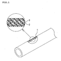
- FIG. 1 A schematic view (partially enlarged cross-sectional view) illustrating construction of a resin hose of the present invention.
- a resin hose of the present invention includes a resin layer containing an aliphatic polyamide (A) and a semi-aromatic polyamide (B) as main components thereof, and containing diisobutyl adipate (C).
- the main components mean components which largely affect the characteristics of the resin layer, and the content of such components is generally 50 wt% or more of the entirety of a resin composition which forms the resin layer.
- the significant feature resides in that the resin layer is formed of a sea phase formed of the components (A) to (C), and needle-like island phases each formed only of the semi-aromatic polyamide (B), the needle-like island phases being arranged along the longitudinal direction of the hose.
- each component constituting the resin composition which forms the resin layer is specifically described.
- Examples of the aliphatic polyamide (A) include polyamide 46 (PA46), polyamide 6 (PA6), polyamide 66 (PA66), polyamide 92 (PA92), polyamide 99 (PA99), polyamide 610 (PA610), polyamide 612 (PA612), polyamide 11 (PA11), polyamide 912 (PA912), polyamide 12 (PA12), a copolymer of polyamide 6 and polyamide 66 (PA6/66), and a copolymer of polyamide 6 and polyamide 12 (PA6/12).
- One kind of those polyamides is used alone, or two or more kinds thereof are used in combination. Of those, from the viewpoints of heat resistance and resistance to a snow melting agent, PA612 is preferred.
- Examples of the semi-aromatic polyamide (B) include polyamide 4T (PA4T), polyamide 6T (PA6T), polyamide MXD6 (PAMXD6), polyamide 9T (PA9T), polyamide 10T (PA10T), polyamide 11T (PA11T), polyamide 12T (PA12T), and polyamide 13T (PA13T).
- PA4T polyamide 4T
- PA6T polyamide 6T
- PAMXD6 polyamide MXD6
- PAMXD6 polyamide MXD6
- PA9T polyamide 9T
- PA9T polyamide 10T
- PA10T polyamide 11T
- PA11T polyamide 12T
- PA12T polyamide 12T
- PA13T polyamide 13T
- PA9T is preferred.
- the amount of the aliphatic polyamide (A) is excessively small (the amount of the component (B) is excessively large), there is observed such a tendency that flexibility is poor, and, when the amount of the aliphatic polyamide (A) is excessively large (the amount of the component (B) is excessively small), there is observed such a tendency that fuel barrier property and rigidity are deteriorated.
- the diisobutyl adipate (C) has an action of inhibiting the aliphatic polyamide (A) and the semi-aromatic polyamide (B) from falling into a completely compatible state.
- the content of the diisobutyl adipate (C) falls within the range of preferably 0.1 part by weight or more and less than 2 parts by weight, particularly preferably 0.5 to 1. 5 parts by weight with respect to 100 parts by weight of the total of the aliphatic polyamide (A) and the semi-aromatic polyamide (B) ((A)+(B)).
- the content of the diisobutyl adipate (C) falls outside the range, there is observed such a tendency that diisobutyl adipate (C) is present alone, and fuel barrier property is deteriorated.
- the resin composition for forming the resin layer of the present invention there may be appropriately blended, for example, an impact modifier, a plasticizer, a filler, an anti-hydrolysis material, an agent for heat-resisting and anti-oxidizing, a UV protection agent, an antioxidant, a softening component, a nucleating agent, and a lubricant in addition to the components (A) to (C) as required.
- an impact modifier for example, a plasticizer, a filler, an anti-hydrolysis material, an agent for heat-resisting and anti-oxidizing, a UV protection agent, an antioxidant, a softening component, a nucleating agent, and a lubricant in addition to the components (A) to (C) as required.
- the impact modifier is used from the viewpoints of improving the flexibility and the impact resistance, and examples thereof include an ionomer resin, a modified polyolefin, a polyether amide elastomer, a polyester amide elastomer, a polyether ester amide elastomer, a polyether ester elastomer, an acrylic rubber, an ethylene-propylene-based rubber, a butyl rubber, a nitrile rubber, a fluororubber, and a silicone rubber.
- an ionomer resin e.g., ethylene-propylene-based rubber, a butyl rubber, a nitrile rubber, a fluororubber, and a silicone rubber.
- the content of the impact modifier is 0.1 to 10 parts by weight, preferably 3 to 5 parts by weight with respect to 100 parts by weight of the total of the aliphatic polyamide (A) and the semi-aromatic polyamide (B) ((A)+(B)).
- one kind or more compounds selected from alkylamides are preferred, and examples thereof include N-ethyl-o-toluenesulfonic acid butylamide, N-ethyl-p-toluenesulfonic acid butylamide, N-ethyl-p-toluenesulfonic acid 2-ethylhexylamide, N-propyl-p-toluenesulfonic acid amide, p-toluenesulfonic acid 1-ethylhexyl ester, and N-butylbenzenesulfonamide.
- One kind of those compounds is used alone, or two or more kinds thereof are used in combination.
- the content of the plasticizer is 0.1 to 10 parts by weight, preferably 3 to 5 parts by weight with respect to 100 parts by weight of the total of the aliphatic polyamide (A) and the semi-aromatic polyamide (B) ((A)+(B)).
- the resin composition may be produced, for example, as follows. That is, the resin composition may be prepared by appropriately blending the aliphatic polyamide (A), the semi-aromatic polyamide (B), and the diisobutyl adipate (C) with other components such as the impact modifier and the plasticizer as required, and kneading the mixture with a co-rotating twin-screw kneader, or the like.
- FIG. 1 is a schematic view (partially enlarged cross-sectional view) illustrating a resin hose having a single-layer structure formed only of a resin layer 1.
- needle-like island phases 3 each formed only of the semi-aromatic polyamide (B) are dispersed in a sea phase 2 containing the aliphatic polyamide (A) and the semi-aromatic polyamide (B) as main components thereof, and containing diisobutyl adipate (C).
- the needle-like island phases 3 are arranged along the longitudinal direction (extrusion direction) of the hose.
- the needle-like island phases 3 are arranged along the longitudinal direction (extrusion direction) of the hose so that a diameter (D1) of each of the needle-like island phases 3 that are arranged in the vicinity of the inner peripheral surface of the hose and in the vicinity of the outer peripheral surface of the hose is shorter than a diameter (D2) of each of the needle-like island phases 3 which are arranged in the central portion of the hose.
- the needle-like island phases 3 When the needle-like island phases 3 are arranged as described above, the needle-like island phases 3, which are short in diameter, and arranged in the vicinity of the inner peripheral surface of the hose and in the vicinity of the outer peripheral surface of the hose, mainly allow the flexibility to be secured, and the needle-like island phases 3, which are long in diameter and arranged in the central portion of the hose, mainly allow the barrier property to be secured. As a result, a balance between the flexibility and the barrier property is improved.
- the diameter (D1) of each of the needle-like island phases 3, which are arranged in the vicinity of the inner peripheral surface of the hose and in the vicinity of the outer peripheral surface of the hose, is generally 10 to 40 nm, preferably 20 to 30 nm
- the diameter (D2) of each of the needle-like island phases 3 which are arranged in the central portion of the hose is generally 40 to 70 nm, preferably 40 to 60 nm.
- the arrangement state of the needle-like island phases 3 in the resin layer 1 may be verified or recognized, for example, with a transmission electron microscope (TEM), or the like.
- TEM transmission electron microscope
- the resin composition is prepared in accordance with the above-mentioned method, and is subjected to extrusion molding on a mandrel into a hose shape.
- a resin hose having a single-layer structure formed only of the resin layer 1 of a tubular shape can be produced.
- a shearing force generated by the extrusion allows the needle-like island phases 3 to be arranged along the longitudinal direction (extrusion direction) of the hose. It should be noted that the use of the mandrel may be omitted.
- a temperature at the time of the extrusion molding is preferably 250 to 350°C, particularly preferably 260 to 330°C.
- the temperature is excessively low, there is observed such a tendency that the extrusion molding cannot be performed owing to an increase in viscosity.
- the temperature is excessively high, there is observed such a tendency that the components (A) and (B) are melted to fall into a completely compatible state, and hence the needle-like island phases 3 are not formed.
- the speed of the extrusion is generally 1 to 30 m/min, preferably 5 to 20 m/min.
- a screw rotation number is generally 10 to 600 rpm, preferably 20 to 150 rpm, and a discharge amount is generally 2 g/min to 100 kg/min, preferably 20 g/min to 3 kg/min.
- the temperature may be controlled through water cooling treatment, oil bath treatment, or the like to control the arrangement state of the needle-like island phases 3.
- the resin hose of the present invention is not limited to the single-layer structure formed only of the special resin layer 1 (see FIG. 1 ), and may have a multi-layer structure of two or more layers as appropriate depending on the application of the hose.
- a rubber layer may be formed on the inner peripheral side or outer peripheral side of the resin layer 1, and a reinforcing layer formed of reinforcing threads or the like may be interposed between the constituent layers of the hose.
- the hose inner diameter and hose outer diameter of the resin hose of the present invention which vary depending on the application of the hose, are generally 1 to 69.5 mm and generally 1.5 to 70 mm, respectively.
- the thickness of the resin layer 1 is generally 0.25 to 20 mm, preferably 0.5 to 5 mm.
- Resin compositions were prepared in accordance with Example 1 except that the kinds, blending amounts, and the like of the components were changed as shown in Table 1 below. Then, in accordance with Example 1, resin hoses each having a single-layer structure were produced using the resin compositions.
- FC/E10 mixed fuel liquid
- Resin films which are obtained by subjecting each of the resin compositions of Examples and Comparative Examples to extrusion molding (260 to 280°C) with a single-layer extruder having a T-die head, were used in measurements of tensile moduli of elasticity (MPa) in accordance with JIS K7161.
- MPa tensile moduli of elasticity
- the resin hose of the present invention may be used as, for example, a fuel hose or a refrigerant-transporting hose (such as an air conditioner hose or a radiator hose) of an automobile, and, in addition to the automobile, may also be used for, for example, other transport machines (such as industrial transport vehicles including an aircraft, a forklift, an excavator, and a crane, and railroad vehicles).
- a fuel hose or a refrigerant-transporting hose such as an air conditioner hose or a radiator hose
- other transport machines such as industrial transport vehicles including an aircraft, a forklift, an excavator, and a crane, and railroad vehicles.
Landscapes
- Engineering & Computer Science (AREA)
- Mechanical Engineering (AREA)
- Rigid Pipes And Flexible Pipes (AREA)
- Extrusion Moulding Of Plastics Or The Like (AREA)
- Compositions Of Macromolecular Compounds (AREA)
Abstract
To provide a resin hose excellent in barrier property (fuel barrier property or gas barrier property) and flexibility, the resin hose includes a resin layer (1) containing the following components (A) and (B) as main components thereof, and containing the following component (C):
(A) an aliphatic polyamide;
(B) a semi-aromatic polyamide; and
(C) diisobutyl adipate,
in which the resin layer (1) is formed of a sea phase (2) formed of the components (A) to (C), and needle-like island phases (3) each formed only of the component (B), the needle-like island phases (3) being arranged along a longitudinal direction of the hose.
(A) an aliphatic polyamide;
(B) a semi-aromatic polyamide; and
(C) diisobutyl adipate,
in which the resin layer (1) is formed of a sea phase (2) formed of the components (A) to (C), and needle-like island phases (3) each formed only of the component (B), the needle-like island phases (3) being arranged along a longitudinal direction of the hose.
Description
- The present invention relates to a resin hose and a method of producing the same, and more specifically, to a resin hose to be used as, for example, a fuel hose or a refrigerant-transporting hose (such as an air conditioner hose or a radiator hose) of an automobile, and a method of producing the same.
- A fuel hose to be mounted on an automobile or the like is demanded to have both of flexibility and barrier property (low permeability). To meet the demand, combined use of a semi-aromatic polyamide and an aliphatic polyamide has been considered (see, for example, Patent Literatures 1 and 2).
-
- [PTL 1]
JP 2004-352790 A - [PTL 2]
JP 2010-77221 A - However, when the semi-aromatic polyamide and the aliphatic polyamide are simply used in combination, both the components completely mix with each other to fall into a completely compatible state, resulting in insufficient barrier property and flexibility.
- The present invention has been made in view of such circumstances, and an object of the present invention is to provide a resin hose which is excellent in barrier property (fuel barrier property or gas barrier property) and flexibility, and a method of producing the same.
- The inventors of the present invention have made extensive studies in order to obtain a resin hose, such as a fuel hose, which is excellent in barrier property (fuel barrier property or gas barrier property) and flexibility. In the course of the studies, the inventors have found the following. When an aliphatic polyamide (A) and a semi-aromatic polyamide (B) are simply mixed, both the components completely mix with each other to fall into a completely compatible state, and hence only the average performance of the components (A) and (B) can be obtained. However, when diisobutyl adipate (C) is used in combination therewith, the aliphatic polyamide (A) and the semi-aromatic polyamide (B) do not fall into a completely compatible state, but fall into a semi-compatible state. This causes needle-like island phases each formed only of the semi-aromatic polyamide (B) to be present in a sea phase containing the aliphatic polyamide (A) and the semi-aromatic polyamide (B) as main components. In addition, the needle-like island phases are arranged along the longitudinal direction (extrusion direction) of the hose, and hence there are obtained barrier property (fuel barrier property or gas barrier property) and flexibility each of which is more excellent than the average performance of the aliphatic polyamide (A) and the semi-aromatic polyamide (B). Thus, the inventors have reached the present invention.
- That is, according to a first gist of the present invention, there is provided a resin hose, including a resin layer containing the following components (A) and (B) as main components thereof, and containing the following component (C):
- (A) an aliphatic polyamide;
- (B) a semi-aromatic polyamide; and
- (C) diisobutyl adipate,
- Further, according to a second gist of the preset invention, there is provided a method of producing the above-mentioned resin hose, the method including extrusion at a temperature of from 260 to 330°C.
- As described above, the resin hose of the present invention includes the resin layer formed of the sea phase formed of the components (A) to (C), and the needle-like island phases each formed only of the component (B), the needle-like island phases being arranged along a longitudinal direction (extrusion direction) of the hose. Therefore, the diffusion of a fuel, etc., in the thickness direction of the hose (direction from the inner peripheral side of the hose toward the outer peripheral side thereof) is inhibited by the needle-like island phases. As a result, the fuel, etc., diffuse in the direction from the inner peripheral side of the hose toward the outer peripheral side thereof in such a manner that the fuel, etc. , thread their ways through the needle-like island phases arranged along the longitudinal direction of the hose. Accordingly, the diffusion paths of the fuel, etc., become longer as compared to the case of linear diffusion in the thickness direction of the hose, and hence the barrier property (fuel barrier property or gas barrier property) is improved. Further, the sea phase (base material) of the resin layer contains as main components the aliphatic polyamide (A) and the semi-aromatic polyamide (B) in a semi-compatible state, and hence the flexibility of the hose is excellent as well.
- [
FIG. 1 ] A schematic view (partially enlarged cross-sectional view) illustrating construction of a resin hose of the present invention. - Next, embodiments of the present invention are described in detail. However, the present invention is not limited to these embodiments.
- A resin hose of the present invention includes a resin layer containing an aliphatic polyamide (A) and a semi-aromatic polyamide (B) as main components thereof, and containing diisobutyl adipate (C).
- It should be noted that, in the present invention, the main components mean components which largely affect the characteristics of the resin layer, and the content of such components is generally 50 wt% or more of the entirety of a resin composition which forms the resin layer.
- In the present invention, the significant feature resides in that the resin layer is formed of a sea phase formed of the components (A) to (C), and needle-like island phases each formed only of the semi-aromatic polyamide (B), the needle-like island phases being arranged along the longitudinal direction of the hose.
- First, each component constituting the resin composition which forms the resin layer is specifically described.
- Examples of the aliphatic polyamide (A) include polyamide 46 (PA46), polyamide 6 (PA6), polyamide 66 (PA66), polyamide 92 (PA92), polyamide 99 (PA99), polyamide 610 (PA610), polyamide 612 (PA612), polyamide 11 (PA11), polyamide 912 (PA912), polyamide 12 (PA12), a copolymer of polyamide 6 and polyamide 66 (PA6/66), and a copolymer of polyamide 6 and polyamide 12 (PA6/12). One kind of those polyamides is used alone, or two or more kinds thereof are used in combination. Of those, from the viewpoints of heat resistance and resistance to a snow melting agent, PA612 is preferred.
- Examples of the semi-aromatic polyamide (B) include polyamide 4T (PA4T), polyamide 6T (PA6T), polyamide MXD6 (PAMXD6), polyamide 9T (PA9T), polyamide 10T (PA10T), polyamide 11T (PA11T), polyamide 12T (PA12T), and polyamide 13T (PA13T). One kind of those polyamides is used alone, or two or more kinds thereof are used in combination. Of those, in terms of fuel barrier property, hydrolysis resistance, and rigidity, PA9T is preferred.
- In the present invention, the weight mixing ratio of the aliphatic polyamide (A) to the semi-aromatic polyamide (B) is preferably (A)/(B)=10/90 to 60/40, particularly preferably (A)/(B)=10/90 to 30/70. When the amount of the aliphatic polyamide (A) is excessively small (the amount of the component (B) is excessively large), there is observed such a tendency that flexibility is poor, and, when the amount of the aliphatic polyamide (A) is excessively large (the amount of the component (B) is excessively small), there is observed such a tendency that fuel barrier property and rigidity are deteriorated.
- The diisobutyl adipate (C) has an action of inhibiting the aliphatic polyamide (A) and the semi-aromatic polyamide (B) from falling into a completely compatible state.
- The content of the diisobutyl adipate (C) falls within the range of preferably 0.1 part by weight or more and less than 2 parts by weight, particularly preferably 0.5 to 1. 5 parts by weight with respect to 100 parts by weight of the total of the aliphatic polyamide (A) and the semi-aromatic polyamide (B) ((A)+(B)). When the content of the diisobutyl adipate (C) falls outside the range, there is observed such a tendency that diisobutyl adipate (C) is present alone, and fuel barrier property is deteriorated.
- It should be noted that, in the resin composition for forming the resin layer of the present invention, there may be appropriately blended, for example, an impact modifier, a plasticizer, a filler, an anti-hydrolysis material, an agent for heat-resisting and anti-oxidizing, a UV protection agent, an antioxidant, a softening component, a nucleating agent, and a lubricant in addition to the components (A) to (C) as required.
- The impact modifier is used from the viewpoints of improving the flexibility and the impact resistance, and examples thereof include an ionomer resin, a modified polyolefin, a polyether amide elastomer, a polyester amide elastomer, a polyether ester amide elastomer, a polyether ester elastomer, an acrylic rubber, an ethylene-propylene-based rubber, a butyl rubber, a nitrile rubber, a fluororubber, and a silicone rubber. One kind of those agents is used alone, or two or more kinds thereof are used in combination.
- The content of the impact modifier is 0.1 to 10 parts by weight, preferably 3 to 5 parts by weight with respect to 100 parts by weight of the total of the aliphatic polyamide (A) and the semi-aromatic polyamide (B) ((A)+(B)).
- In addition, as the plasticizer, for example, one kind or more compounds selected from alkylamides are preferred, and examples thereof include N-ethyl-o-toluenesulfonic acid butylamide, N-ethyl-p-toluenesulfonic acid butylamide, N-ethyl-p-toluenesulfonic acid 2-ethylhexylamide, N-propyl-p-toluenesulfonic acid amide, p-toluenesulfonic acid 1-ethylhexyl ester, and N-butylbenzenesulfonamide. One kind of those compounds is used alone, or two or more kinds thereof are used in combination.
- The content of the plasticizer is 0.1 to 10 parts by weight, preferably 3 to 5 parts by weight with respect to 100 parts by weight of the total of the aliphatic polyamide (A) and the semi-aromatic polyamide (B) ((A)+(B)).
- The resin composition may be produced, for example, as follows. That is, the resin composition may be prepared by appropriately blending the aliphatic polyamide (A), the semi-aromatic polyamide (B), and the diisobutyl adipate (C) with other components such as the impact modifier and the plasticizer as required, and kneading the mixture with a co-rotating twin-screw kneader, or the like.
- Next, the resin hose of the present invention is described.
-
FIG. 1 is a schematic view (partially enlarged cross-sectional view) illustrating a resin hose having a single-layer structure formed only of a resin layer 1. - In the resin layer 1, needle-like island phases 3 each formed only of the semi-aromatic polyamide (B) are dispersed in a sea phase 2 containing the aliphatic polyamide (A) and the semi-aromatic polyamide (B) as main components thereof, and containing diisobutyl adipate (C). In addition, the needle-like island phases 3 are arranged along the longitudinal direction (extrusion direction) of the hose.
- In
FIG. 1 , the needle-like island phases 3 are arranged along the longitudinal direction (extrusion direction) of the hose so that a diameter (D1) of each of the needle-like island phases 3 that are arranged in the vicinity of the inner peripheral surface of the hose and in the vicinity of the outer peripheral surface of the hose is shorter than a diameter (D2) of each of the needle-like island phases 3 which are arranged in the central portion of the hose. When the needle-like island phases 3 are arranged as described above, the needle-like island phases 3, which are short in diameter, and arranged in the vicinity of the inner peripheral surface of the hose and in the vicinity of the outer peripheral surface of the hose, mainly allow the flexibility to be secured, and the needle-like island phases 3, which are long in diameter and arranged in the central portion of the hose, mainly allow the barrier property to be secured. As a result, a balance between the flexibility and the barrier property is improved. - The diameter (D1) of each of the needle-like island phases 3, which are arranged in the vicinity of the inner peripheral surface of the hose and in the vicinity of the outer peripheral surface of the hose, is generally 10 to 40 nm, preferably 20 to 30 nm, and the diameter (D2) of each of the needle-like island phases 3 which are arranged in the central portion of the hose, is generally 40 to 70 nm, preferably 40 to 60 nm.
- It should be noted that the arrangement state of the needle-like island phases 3 in the resin layer 1 may be verified or recognized, for example, with a transmission electron microscope (TEM), or the like.
- Next, a method of producing the resin hose of the present invention is described. That is, the resin composition is prepared in accordance with the above-mentioned method, and is subjected to extrusion molding on a mandrel into a hose shape. Thus, a resin hose having a single-layer structure formed only of the resin layer 1 of a tubular shape can be produced. A shearing force generated by the extrusion allows the needle-like island phases 3 to be arranged along the longitudinal direction (extrusion direction) of the hose. It should be noted that the use of the mandrel may be omitted.
- A temperature at the time of the extrusion molding is preferably 250 to 350°C, particularly preferably 260 to 330°C. When the temperature is excessively low, there is observed such a tendency that the extrusion molding cannot be performed owing to an increase in viscosity. When the temperature is excessively high, there is observed such a tendency that the components (A) and (B) are melted to fall into a completely compatible state, and hence the needle-like island phases 3 are not formed.
- The speed of the extrusion is generally 1 to 30 m/min, preferably 5 to 20 m/min. Further, a screw rotation number is generally 10 to 600 rpm, preferably 20 to 150 rpm, and a discharge amount is generally 2 g/min to 100 kg/min, preferably 20 g/min to 3 kg/min.
- It should be noted that, after the extrusion step, the temperature may be controlled through water cooling treatment, oil bath treatment, or the like to control the arrangement state of the needle-like island phases 3.
- The resin hose of the present invention is not limited to the single-layer structure formed only of the special resin layer 1 (see
FIG. 1 ), and may have a multi-layer structure of two or more layers as appropriate depending on the application of the hose. A rubber layer may be formed on the inner peripheral side or outer peripheral side of the resin layer 1, and a reinforcing layer formed of reinforcing threads or the like may be interposed between the constituent layers of the hose. - The hose inner diameter and hose outer diameter of the resin hose of the present invention, which vary depending on the application of the hose, are generally 1 to 69.5 mm and generally 1.5 to 70 mm, respectively. The thickness of the resin layer 1 is generally 0.25 to 20 mm, preferably 0.5 to 5 mm.
- Hereinafter, the present invention is more specifically described by way of examples. However, the present invention is not limited to the following examples without departing from the scope of the invention.
- First, prior to Examples and Comparative Example, the following materials were prepared.
(Aliphatic polyamide (A))
PA612 (DIAMID D22 manufactured by DAICEL-EVONIK. LTD.)
(Semi-aromatic polyamide (B))
PA9T (N1001D-U03 manufactured by KURARAY CO., LTD.)
(Diisobutyl adipate (C))
Diisobutyl adipate manufactured by WAKO PURE CHEMICAL INDUSTRY
(Impact modifier)
Maleic anhydride-modified ethylene-butene copolymer (TAFMER MH7020 manufactured by MITSUI CHEMICALS, INC.)
(Plasticizer)
N-Butylbenzenesulfonamide (BM-4 manufactured by DAIHACHI CHEMICAL INDUSTRY CO., LTD.) - Components shown in Table 1 below were blended at ratios shown in the table, and were kneaded with a co-rotating twin-screw kneader to prepare a resin composition. Then, the resin composition was subjected to extrusion molding with an extrusion molding machine (manufactured by Japan Steel Works, Ltd., TEX30α) to produce a resin hose having a single-layer structure (inner diameter: 6 mm, outer diameter: 8 mm).
- It should be noted that the conditions at the time of the extrusion molding were asfollows:extrusion temperature: 280°C, extrusion speed: 5m/min, screw rotation number: 40 rpm, and discharge amount: 100 g/min.
- Resin compositions were prepared in accordance with Example 1 except that the kinds, blending amounts, and the like of the components were changed as shown in Table 1 below. Then, in accordance with Example 1, resin hoses each having a single-layer structure were produced using the resin compositions.
- [Table 1]
(Part(s) by weight) Example Comparative Example 1 2 3 4 5 6 1 2 3 4 5 Aliphatic polyamide (A) 10 30 50 60 10 10 - 70 10 60 30 Semi-aromatic polyamide (B) 90 70 50 40 90 90 100 30 90 40 70 Diisobutyl adipate (C) 0.5 0.5 0.5 0.5 0.1 1.5 0.5 0.5 - - 2 Impact modifier 5 5 5 5 5 5 5 5 5 5 5 Plasticizer 5 5 5 5 5 5 5 5 5 5 5 Fuel permeation amount (mg·mm/cm2/day) 0.45 0.5 0.52 045 0.43 0.41 <0.1 2.3 1.4 1.8 1.2 Fuel barrier property (evaluation) ○ ○ ○ ○ ○ ○ ○ × × × × Tensile modulus of elasticity (MPa) 1,530 1,480 1,540 1,250 1,560 1,580 1, 890 860 1,150 1,080 1,520 Rigidity (evaluation) ○ ○ ○ ○ ○ ○ × × × × ○ Presence or absence of needle-like island phases ○ ○ ○ ○ ○ ○ × × × × × - The thus obtained products of Examples and Comparative Examples were used in evaluations for respective characteristics based on the following criteria. Table 1 above also shows the results of the evaluations.
- A hose having both ends sealed with Swagelok fittings was filled with a mixed fuel liquid (FC/E10) of Fuel C (toluene: isooctane=50: 50 (on a volume basis)) and ethanol (Fuel C:ethanol=90:10 (on a volume basis)), and was then left to stand at 40°C for 1 month to be stabilized. After that, the content (mixed fuel) was discharged. Next, the hose was filled again with a fresh mixed fuel (FC/E10), and was then left to stand in a predetermined temperature cycle environment and measured for its fuel permeation amount every 24 hours. This operation was repeated three times, and the largest value among the three measured values was defined as a fuel permeation amount in a single test. In the evaluation, a case where the fuel permeation amount was 0.75 or less (mg·mm/cm2/day) was represented by Symbol "○", and a case where the fuel permeation amount was more than 0.75 (mg·mm/cm2/day) was represented by Symbol "x".
- Resin films, which are obtained by subjecting each of the resin compositions of Examples and Comparative Examples to extrusion molding (260 to 280°C) with a single-layer extruder having a T-die head, were used in measurements of tensile moduli of elasticity (MPa) in accordance with JIS K7161. In the evaluation, a case where the tensile modulus of elasticity was 1,200 to 1,800 MPa was represented by Symbol "○", and a case where the the tensile modulus of elasticity was less than 1,200 MPa or more than 1,800 MPa was represented by Symbol "×".
- The presence or absence of the needle-like island phases in the resin layer of each hose was observed with a TEM (manufactured by JEOL Ltd. , JEM-2100). In the evaluation, a case where needle-like island phases each formed only of the semi-aromatic polyamide (B) were present in a sea phase containing the aliphatic polyamide (A) and the semi-aromatic polyamide (B) as main components thereof, and the needle-like island phases were arranged along the longitudinal direction (extrusion direction) of the hose, was represented by Symbol "○", and a case where the needle-like island phases were not present, was represented by Symbol "×".
- As apparent from the foregoing results, all the products of Examples had the needle-like island phases arranged along the longitudinal direction (extrusion direction) of the hose, and hence were excellent in fuel barrier property and rigidity.
- In contrast, all the products of Comparative Examples had no needle-like island phases arranged therein, and hence were poor in at least one of fuel barrier property and rigidity.
- It should be noted that, although specific embodiments of the present invention are described in Examples above, Examples above are for illustrative purposes only and are not to be construed as limitative. It is intended that various modifications apparent to a person skilled in the art are within the scope of the present invention.
- The resin hose of the present invention may be used as, for example, a fuel hose or a refrigerant-transporting hose (such as an air conditioner hose or a radiator hose) of an automobile, and, in addition to the automobile, may also be used for, for example, other transport machines (such as industrial transport vehicles including an aircraft, a forklift, an excavator, and a crane, and railroad vehicles).
-
- 1
- resin layer
- 2
- sea phase
- 3
- needle-like island phase
Claims (5)
- A resin hose, comprising a resin layer containing the following components (A) and (B) as main components thereof, and containing the following component (C):(A) an aliphatic polyamide;(B) a semi-aromatic polyamide; and(C) diisobutyl adipate,
wherein the resin layer is formed of
a sea phase formed of the components (A) to (C), and needle-like island phases each formed only of the component (B), the needle-like island phases being arranged along a longitudinal direction of the resin hose. - A resin hose as claimed in claim 1, wherein a weight ratio of the component (A) to the component (B) falls within a range of (A)/(B)=10/90 to 60/40.
- A resin hose as claimed in claim 1 or 2, wherein a content of the component (C) falls within a range of 0.1 part by weight or more and less than 2 parts by weight with respect to 100 parts by weight of a total of the component (A) and the component (B).
- A method of producing a resin hose according to any one of claims 1 to 3, the method comprising extrusion at a temperature of from 260 to 330°C.
- A method of producing a resin hose as claimed in claim 4, wherein arrangement of needle-like island phases along a longitudinal direction of the resin hose is formed by a shearing force in the extrusion.
Applications Claiming Priority (2)
| Application Number | Priority Date | Filing Date | Title |
|---|---|---|---|
| JP2012016285A JP5963162B2 (en) | 2012-01-30 | 2012-01-30 | Resin hose and its manufacturing method |
| PCT/JP2012/077262 WO2013114689A1 (en) | 2012-01-30 | 2012-10-22 | Resin hose and method for producing same |
Publications (1)
| Publication Number | Publication Date |
|---|---|
| EP2811212A1 true EP2811212A1 (en) | 2014-12-10 |
Family
ID=48904755
Family Applications (1)
| Application Number | Title | Priority Date | Filing Date |
|---|---|---|---|
| EP12867529.5A Withdrawn EP2811212A1 (en) | 2012-01-30 | 2012-10-22 | Resin hose and method for producing same |
Country Status (5)
| Country | Link |
|---|---|
| US (1) | US20130216751A1 (en) |
| EP (1) | EP2811212A1 (en) |
| JP (1) | JP5963162B2 (en) |
| CN (1) | CN103339430B (en) |
| WO (1) | WO2013114689A1 (en) |
Families Citing this family (7)
| Publication number | Priority date | Publication date | Assignee | Title |
|---|---|---|---|---|
| RU2678031C2 (en) * | 2014-04-10 | 2019-01-22 | Мицубиси Гэс Кемикал Компани, Инк. | Moulded body and manufacturing method thereof |
| CN107075251B (en) * | 2014-11-20 | 2020-07-14 | 东丽株式会社 | Polyamide resin composition for molded article in contact with high-pressure hydrogen, and molded article using same |
| JP7415121B2 (en) | 2019-07-30 | 2024-01-17 | 横浜ゴム株式会社 | Piping system for air conditioners installed in automobiles |
| JP7617380B2 (en) | 2021-01-06 | 2025-01-20 | 横浜ゴム株式会社 | Resin material for hoses and hoses |
| CN117651823A (en) | 2021-07-29 | 2024-03-05 | 横滨橡胶株式会社 | Hose for conveying refrigerant |
| DE112022003794T5 (en) | 2021-07-29 | 2024-05-29 | The Yokohama Rubber Co., Ltd. | Refrigerant transport hose |
| US20230264459A1 (en) * | 2022-01-10 | 2023-08-24 | Cooper-Standard Automotive Inc. | High temperature multi-layer coolant tube |
Family Cites Families (12)
| Publication number | Priority date | Publication date | Assignee | Title |
|---|---|---|---|---|
| US4006115A (en) * | 1974-12-26 | 1977-02-01 | Monsanto Company | Phthalate ester containing nylon composition |
| JPH0232515B2 (en) * | 1983-10-27 | 1990-07-20 | Toyoda Gosei Kk | PURASUCHITSUKUHOOSUNOSEIZOHOHO |
| FR2727124B1 (en) * | 1994-11-22 | 1996-12-20 | Atochem Elf Sa | POLYAMIDE-BASED FLEXIBLE TRANSLUCENT COMPOSITION, PROCESS FOR CONVERTING SAME, AND ARTICLES OBTAINED THEREFROM |
| AU2001236043A1 (en) * | 2000-03-03 | 2001-09-12 | Toyoda Gosei Co. Ltd. | Resin hose for fuel |
| CA2386717A1 (en) * | 2001-05-21 | 2002-11-21 | Kuraray Co., Ltd. | Polyamide composition |
| JP4106655B2 (en) | 2003-05-27 | 2008-06-25 | 宇部興産株式会社 | Plasticizer-containing resin composition and molded product |
| JP2005128067A (en) * | 2003-10-21 | 2005-05-19 | Tokai Rubber Ind Ltd | Developing roll |
| CN100519167C (en) * | 2004-04-27 | 2009-07-29 | 宇部兴产株式会社 | Multilayer hose for transporting high-temperature chemical and/or gas |
| JP2008246916A (en) * | 2007-03-30 | 2008-10-16 | Nof Corp | Bellows molded product and manufacturing method thereof |
| JP5584968B2 (en) * | 2008-09-24 | 2014-09-10 | 宇部興産株式会社 | Plasticizer-containing polyamide resin composition and molded article |
| CN102112545A (en) * | 2008-07-30 | 2011-06-29 | 纳幕尔杜邦公司 | Copolyetherester compositions and articles made from these |
| JP2011226940A (en) * | 2010-04-21 | 2011-11-10 | Ube Ind Ltd | Evaluation method for impact property of tube, producing method for tube, and tube with excellent impact toughness |
-
2012
- 2012-01-30 JP JP2012016285A patent/JP5963162B2/en not_active Expired - Fee Related
- 2012-10-22 CN CN201280004068.6A patent/CN103339430B/en not_active Expired - Fee Related
- 2012-10-22 EP EP12867529.5A patent/EP2811212A1/en not_active Withdrawn
- 2012-10-22 WO PCT/JP2012/077262 patent/WO2013114689A1/en not_active Ceased
-
2013
- 2013-03-15 US US13/838,484 patent/US20130216751A1/en not_active Abandoned
Non-Patent Citations (1)
| Title |
|---|
| See references of WO2013114689A1 * |
Also Published As
| Publication number | Publication date |
|---|---|
| JP2013155793A (en) | 2013-08-15 |
| US20130216751A1 (en) | 2013-08-22 |
| JP5963162B2 (en) | 2016-08-03 |
| WO2013114689A1 (en) | 2013-08-08 |
| CN103339430A (en) | 2013-10-02 |
| CN103339430B (en) | 2015-12-09 |
Similar Documents
| Publication | Publication Date | Title |
|---|---|---|
| US20130216751A1 (en) | Resin hose and method of producing the same | |
| KR101138533B1 (en) | Impact-modified polyamide hollow body | |
| JP7399150B2 (en) | Multilayer tubular structure with improved elution resistance in biofuel and use of the multilayer tubular structure | |
| JP4404255B2 (en) | A hollow multilayer thermoplastic multilayer composite | |
| EP3239579B1 (en) | Multilayered tube for transporting liquid medicine and polyamide resin composition | |
| JP5860598B2 (en) | Refrigerant transport hose and manufacturing method thereof | |
| EP2512793B1 (en) | Multilayer structures comprising a barrier layer and their use to convey fluids | |
| EP2684915A1 (en) | Polyethylene-based structure | |
| JP2018515358A (en) | Multilayer tubular structure with improved resistance to elution into biofuel and use of the multilayer tubular structure | |
| EP2551101A1 (en) | Fuel hose | |
| JP2013228081A (en) | Air conditioner hose | |
| KR102472750B1 (en) | Multilayer tube for fuel transportation, fuel pump module provided with same, use of same, and use of fuel pump module | |
| DE112017005273B4 (en) | Hose for conducting a refrigerant | |
| JP5883370B2 (en) | Resin composition for fuel tube and fuel tube | |
| JP4501704B2 (en) | Fuel hose | |
| JP5041095B2 (en) | Polyamide resin composition, method for producing the same, and refrigerant transport hose | |
| JP2007231096A (en) | Method for producing fuel hose material and fuel hose material obtained thereby | |
| JP6441001B2 (en) | Antistatic tube | |
| JP2011006680A5 (en) | ||
| KR102686693B1 (en) | Flexible multilayer compressed-air line | |
| EP2767746B1 (en) | Resin fuel tube | |
| JP2005272673A (en) | Resin tube for automobile piping and manufacturing method thereof |
Legal Events
| Date | Code | Title | Description |
|---|---|---|---|
| PUAI | Public reference made under article 153(3) epc to a published international application that has entered the european phase |
Free format text: ORIGINAL CODE: 0009012 |
|
| 17P | Request for examination filed |
Effective date: 20131010 |
|
| AK | Designated contracting states |
Kind code of ref document: A1 Designated state(s): AL AT BE BG CH CY CZ DE DK EE ES FI FR GB GR HR HU IE IS IT LI LT LU LV MC MK MT NL NO PL PT RO RS SE SI SK SM TR |
|
| AX | Request for extension of the european patent |
Extension state: BA ME |
|
| DAX | Request for extension of the european patent (deleted) | ||
| STAA | Information on the status of an ep patent application or granted ep patent |
Free format text: STATUS: THE APPLICATION HAS BEEN WITHDRAWN |
|
| 18W | Application withdrawn |
Effective date: 20150511 |